

Page 1

Owner’s Manual
Echo™Beds
Owner _________________________
Model ________________________
Serial Number _________________________
Date _________________________
Medical Positioning, Inc. • 1717 Washington • Kansas City, MO 64108 • 800-593-ECHO (3246) • www.medicalpositioning.com
MEDICAL POSITIONING
Page 2

Table of Contents
I. Echo™Bed / Echo™Bed Dual
Echo™Bed / Echo™
Bed Dual Set-Up I - 1
Safety Features I - 3
Patient Positioning I - 4
Sonographer Positioning I - 7
Operation and Annual Maintenance I - 9
1. Hand wand I - 10
2. Drop section I - 12
3. Drop Section Exntension I - 16
4. Non-pinch flap I - 17
5. Caster use I - 18
6. Maintenance I - 20
Operation - All Ways Echo Bed I - 23
Cleaning Instructions I - 26
Troubleshooting Guide I - 28
Warranty I - 30
II. Parts Lists and Diagrams
II - 1
III. Accessories
Collapsible Safety Rail Operation III - 1
Paper Roll Holder Instalation III - 2
Pediatric / Geriatric Adaptor Use III - 3
IV. Specification Sheets IV - 1
EBSPB0606
Page 3
I - 1
Echo™Bed / Echo Bed™Dual Set Up
Introduction
Your Echo™Bed /Echo™Bed Dual has been tested to insure perfect operation on day one. Please closely inspect your Echo™Bed/
Echo™Bed Dual when you receive it to insure no damage has
occurred during shipment. Because the Echo™Bed / Echo™ Bed
Dual is a complex piece of equipment you are offered the following precautions.
To Avoid Injury or Damage
To reduce the risk of electrical shock, do not remove secured covers. Refer ser-
vicing to qualified personnel.
Lock all casters before using equipment.
Place hand wand on hook or holder when not in use. Keep cable clear of mov-
ing parts.
Grounding reliability can only be achieved when the equipment is connected to
an equivalent receptacle marked “hospital only” or “hospital grade”.
Protect vinyl upholstery from sharp objects and abrasion to avoid damage.
Refer to instructions located in this manual for vinyl cleaning recommendations.
Do not use abrasives to clean painted surfaces.
Risk class is 2G.--120 VAC, 50 to 60hz.
(continued)
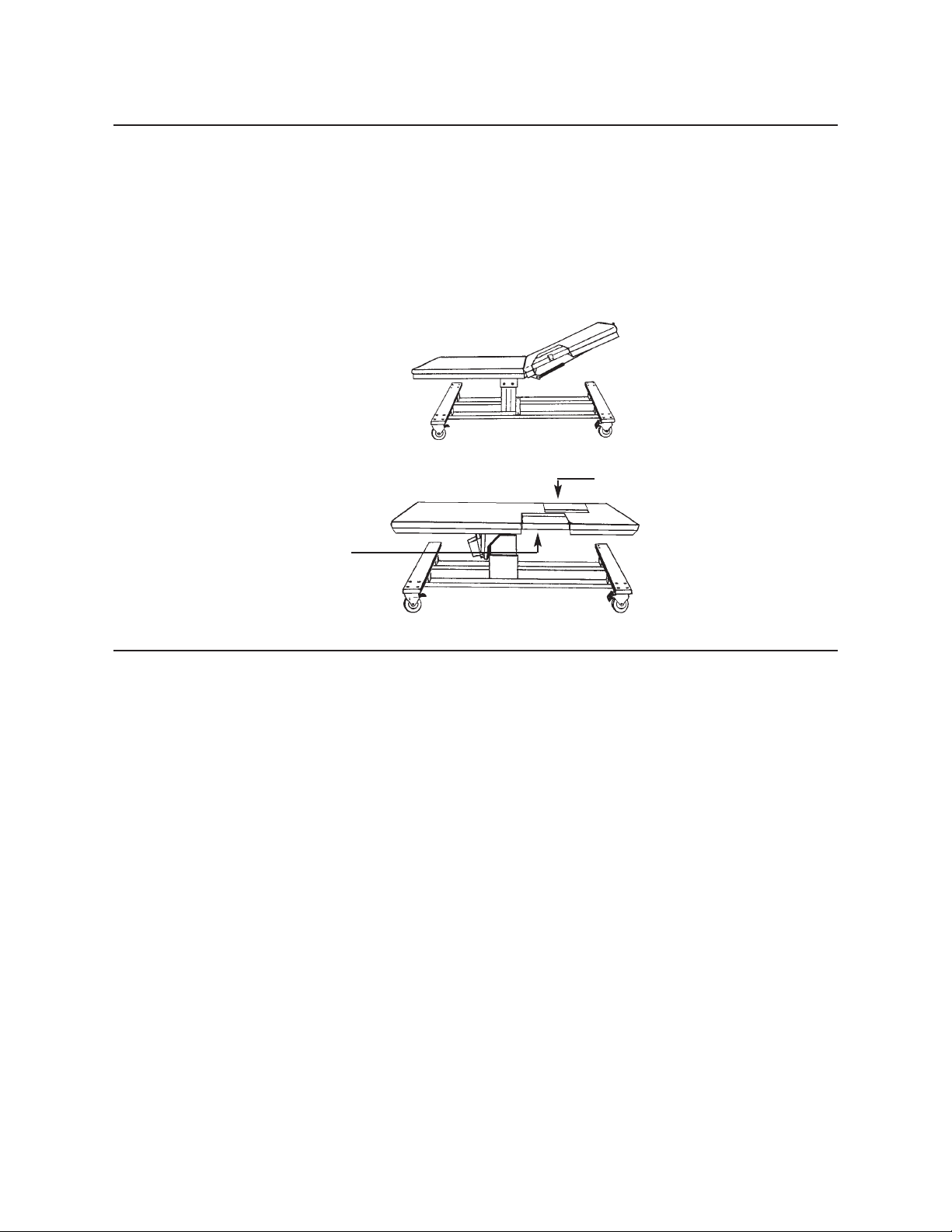
Sonographer’s Entry Drop Section
Imaging Window Drop Section
Echo™Bed
Echo™Bed Dual
Page 4
I - 2
In This Section
Your Echo™Bed /Echo™Bed Dual has been shipped to you in
“plug and play” condition. In this section you will learn how to
program the handwand and perform an initial test of your
Echo™Bed /Echo™Bed Dual to insure that each function is in correct working order. After reviewing this manual you are ready to
begin using your Echo™Bed / Echo™Bed Dual.
System Test Procedure
The hand wand is a low voltage, DC operated device. The cable
begins at the hand wand and plugs into the control box.
Step
Action
1 After removing padding and packaging materials,
locate primary power supply cord and attach to suitable grounded 120
VAC outlet.
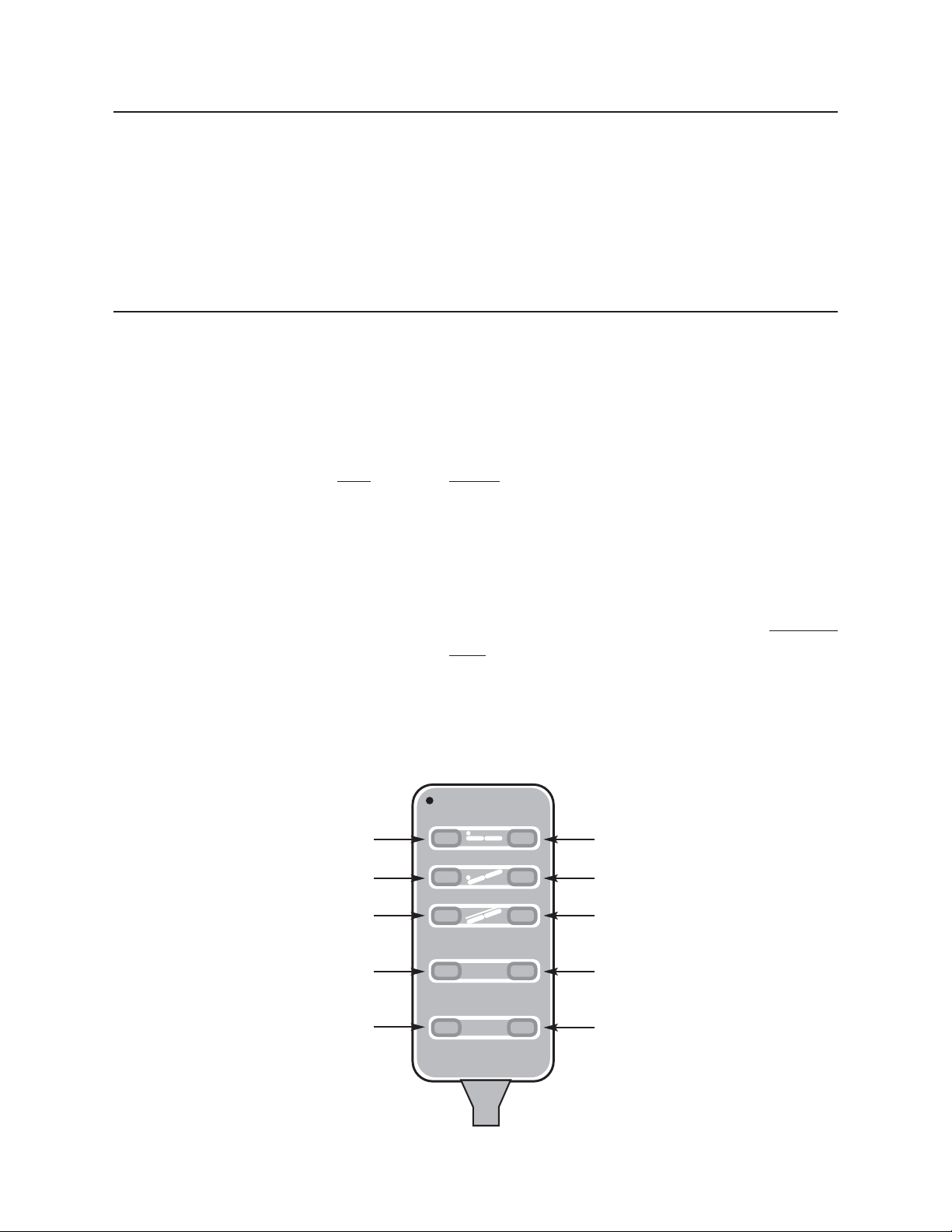
2 To test actuator functions, locate the hand control
wand and depress each function button one at a
time.
(Depressing multiple buttons simultaneously
may prevent motors from operating.)
Figure 1
P 3
M
P
2
P 1
MEDICAL
POSITIONING
BED UP
REVERSE TRENDELENBURG
FOWLER UP
MEMORY POSITION 1
MEMORY POSITION 3
BED DOWN
TRENDELENBURG
FOWLER DOWN
MEMORY POSITION 2
MEMORY SET BUTTON
(Refer to pages I-13 for memory programming instructions.)
Page 5

I - 3
System Test Procedure
Step
Action
3 If any function does not operate, perform the test
procedures listed in the “Troubleshooting Guide”
located in this manual.
Safety Features
In This Section
This section lists the safety features built into your Echo™Bed.
Safety Features
The Echo™Bed is equipped with multiple automated safety features to prevent danger or damage during use. The entire system is
loop-grounded to UL-544 and C.S.A. Hospital Standards.
The actuator assemblies are current overload protected. If overloaded, the actuators will stop and reset automatically.
When equipped with a supine ergometer, electrical current is routed through a UL-544, C.S.A. approved multiple outlet power strip
which utilizes a safety ground-fault circuit breaker.
The sealed hand-held wand operates the actuators by directing
small amounts of low voltage D.C. current to the control box. All
of the actuator drives are equipped with internal limit switches
which automatically prevent over-extension.
The Echo™Bed is equipped with Single pedal braking and steering
casters which can be engaged with the stainless steel lever located
at the center of the base frame.
When equipped with Trendelenburg, a level indicator is located on
the sides of the bed surface to allow quick repositioning to level
after Trendelenburg procedures.
Page 6

I - 4
Patient Positioning
Introduction
Medical Positioning, Inc. is the only provider of the patented drop section which allows a sonographer to:
Place the patient in a full left lateral decubitus position
Improve image clarity
Reduce image acquisition time
Provide uninhibited access to to the apical window
Expand intercostal spaces (with SafeTwedge™)
Reduce foreshortening of apical images
The American Society of Echocardiography provides supporting commentary in the
“Recommendations for Quantitation of Two Dimensional Echocardiograms” on the value of the
drop section as well as the optimum patient position for performing an echocardiogram.
With your imaging surface from Medical Positioning, Inc., you are well-equipped to start
improving the quality of your images.
In This Section
You will learn how to correctly position patients on your imaging surface to optimize the
results of your echo studies. Before you begin,be sure the casters are in the locked position-
-refer to “Caster Use” section for detailed instructions.
Patient Positioning Procedure
Step
Action
1 Place a SafeTwedge™flush with the head end of the
bed (where the drop section is located). The
SafeTwedge™should be evenly centered between
the sides of the bed.
2 With the drop section closed, ask the patient to lie
on their back on the imaging surface.
(continued)
1
Nelson B. Schiller, MD, et al..”Recommendations for Quantitation of the Left Ventricle by Two-Dimensional Echocardiograms,” Journal of the American Society of
Echocardiography, 1989, Vol. 2, pp. 358-367.
It is recommended that for obtaining optimum apical views, the patients be positioned
in steep lateral recumbency for examination. Once this position has been achieved,
it should be maintained with a wedge or pillow...(When) the patient is in a steep left
lateral position, it is frequently difficult to transect the true apex unless there is a mattress with a scoop or excavation at the point where the apex impulse is generally
located...Lack of specialized examining tables makes quantitative measurements
more difficult in the critical care setting where modifying the bed is not practical.
1
Page 7
I - 5
Patient Positioning Procedure (cont.)
Step Action
3 Explain to the patient that you will be opening the
drop section. While the patient will not feel anything, do not surprise the patient by opening the
drop section without warning.
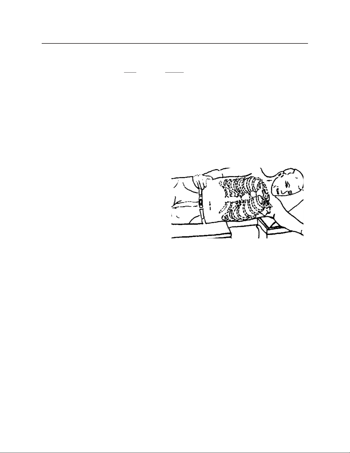
4 Adjust the patient so that he or she is in the middle
of the bed (side to side) and so that the patient’s
armpit or axilla is aligned with the top edge of the
drop section. (See Figure 2)
If there is any question about proper positioning,
roll the patient up onto their left side, open the
Imaging Window Drop Section either remotely or
manually (for instructions on how to operate the
drop section, refer to pages II-14 to II-17) and locate
the patient’s imaging windows. Make any adjustments required to patient position.
If you are beginning a procedure such as a treadmill exercise echo where the patient will be off
and then back on the bed, you should alert the patient to his / her current position and explain
to the patient he / she must assume the same position post exercise. Some sonographers use
tape on the bed to mark the hip location and tell the patient to return to that marked position
following exercise. This technique can be useful, but BE CAREFUL, image windows fre-
quently shift with exercise.
(continued)
Figure 2
Page 8

I - 6
Patient Positioning Procedure (cont.)
Step
Action
5 When imaging (both resting and stress) it is helpful
to ask the patient to place their left hand behind their
head. This keeps their arm clear of the imaging window.
When using this product with small children, senior
citizens or well-endowed women, a Pediatric /
Geriatric Adapter (available from Medical
Positioning, Inc.) may be helpful.
6 Parasternal views can be obtained with the drop sec-
tion either open or closed. When obtaining apical
images, always open the drop section. At the completion of the study, but before the patient gets up to
leave the exam surface, be sure to securely close the
drop section.
Page 9

I - 7
Sonographer Positioning
Introduction
The Echo™Bed Dual is designed to both improve images and maximize sonographer ergonomics. The two drop sections built into
the bed are identified as the Imaging Window Drop Section and the
Sonographer’s Entry Drop Section. The Sonographer's Entry Drop
Section on the right of the patient provides a place for the right
sided sonographer to sit, close to the patient while maintaining an
upright position during imaging.
Once you have properly positioned the patient on his or her left side
over the Imaging Window Drop Section (see Patient Positioning
for instructions) you are ready to place yourself in the proper position, open the Imaging Window Drop Section and begin imaging
the patient.
In This Section
You will learn how to correctly position yourself on your
Echo™Bed Dual in order to insure maximum comfort and continued upright posture while you are imaging your patients.
Sonographer Positioning Procedure
Before you begin this procedure, please familiarize yourself with
the “Patient Positioning Procedure” and the “Operation Section”.
In preparation for an echocardiography study, and before you
work with any patient, lower the Sonographer’s Entry Drop Section
and seat yourself on the table, facing the head of the bed and perpendicular to where the patient will be located. Place your ultrasound unit in close proximity to where you are seated to minimize
the reach from the table to the ultrasound unit. For maximum comfort, it is important that you be able to maintain an upright position
while you are operating both the controls on your ultrasound unit
and the transducer. With your equipment in the proper place, you
are ready to begin working with a patient.
(continued)
Page 10

I - 8
Sonographer Positioning Procedure (cont.)
Step
Action
1 Prior to beginning an echo procedure, familiarize
the patient with the Echo™Bed Dual. Explain to
him/her that you will be opening the drop sections,
that their opening will be slightly noisy, but the
patient will be both comfortable and secure throughout the procedure.
2 Insure the patient is in the correct left lateral decu-
bitus position. Tell the patient that you will be
opening the Sonographer’s Entry Drop Section.
While the patient will not feel anything, do not sur-
prise the patient by opening the drop section without warning. Open the Sonographer’s Entry Drop
Section and enter the cut-out area of the table. Seat
yourself on the table, facing the head of the bed and
perpendicular to the patient.
3 Tell the patient that you will be opening the Imaging
Window Drop Section. Again, the patient will not
feel anything, however, do not surprise the patient
by opening the drop section without warning.
Lower the Imaging Window Drop Section by activating the remote release as described in the
“Remote Drop Section Operation” on page III-18.
4 You are now ready to begin imaging the patient.
Page 11
I - 9
Operation
Introduction
The Echo™Bed / Echo™Bed Dual is shipped assembled and
ready for use. Each function has been pre-tested to insure perfect
working order on day one. Your control wand and Echo™Bed
may not be equipped with all of the described functions. A
“Troubleshooting Guide” is included to instruct you in the event
of a malfunction.
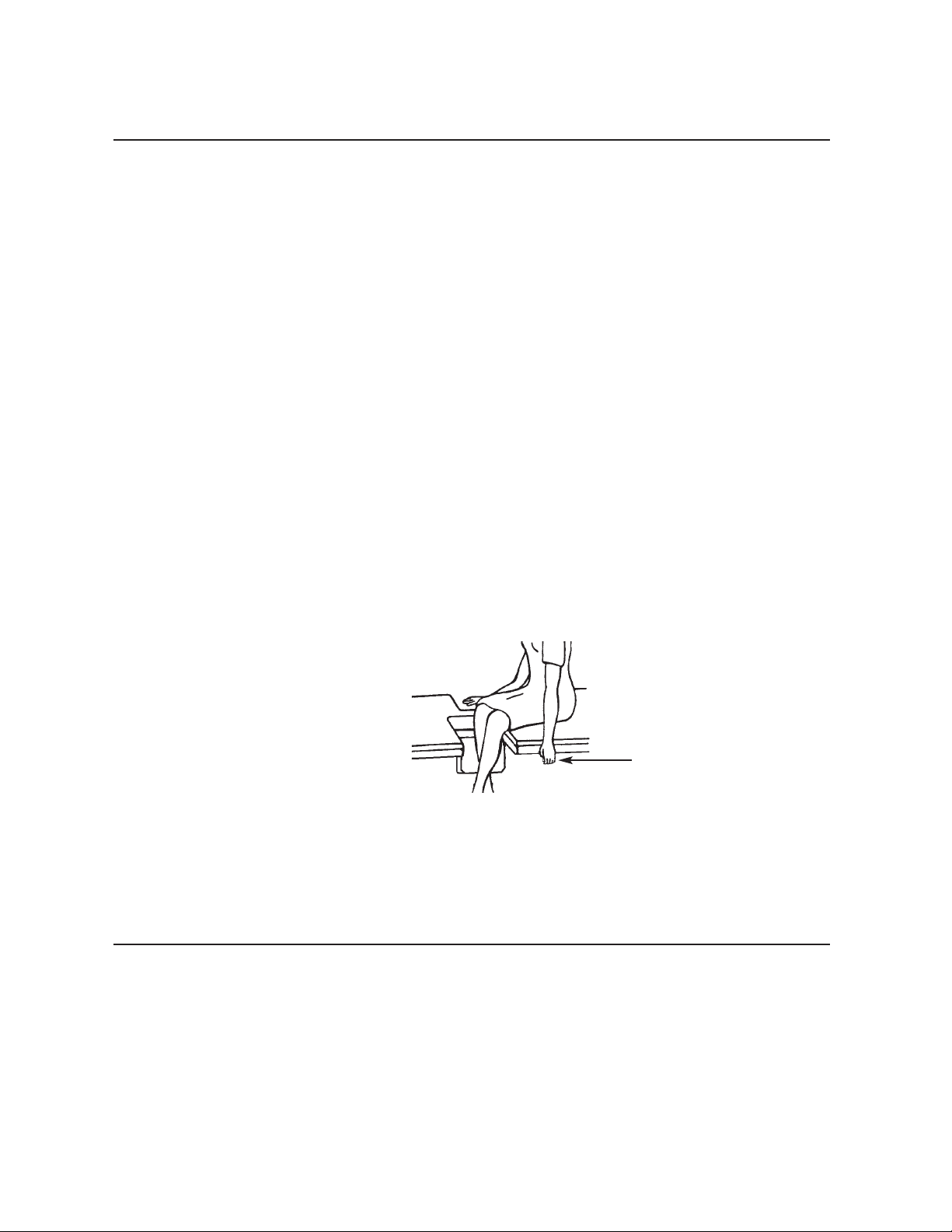
The Echo™Bed is designed for the sonographer that sits on the
left side of the patient. This model is equipped with a single drop
section, the Imaging Window Drop Section.
The Echo™Bed Dual is designed for the sonographer that sits on
the right side of the patient and reaches over the patient to scan.
The Echo™Bed Dual is equipped with two drop sections: 1) An
Imaging Window Drop Section and 2) the Sonographer’s Entry
Drop Section.
The Sonographer's Entry Drop Section on the right of the patient
provides a place for the sonographer to sit, facing the head of the
bed and perpendicular to the patient.
This position, close to the patient, provides several advantages for
the right sided sonographer. First, the sonographer’s drop section
allows increased control of patient location and greater access to
the intercostal imaging areas. In addition, it allows the sonographer to maintain a more upright position and should reduce stress
to the shoulder, back and wrist of the sonographer.
In This Section
You will be provided with a basic understanding of the operation
of the Echo™Bed. You will be instructed on the proper use of the
Echo™Bed; including
--using the hand wand
--operating the drop section & remote drop section
-- sonographers drop section extension
--care of the non-pinch flap
--caster use
--annual maintenance
Remote Release for
Imaging Window Drop
Section
Page 12
I - 10
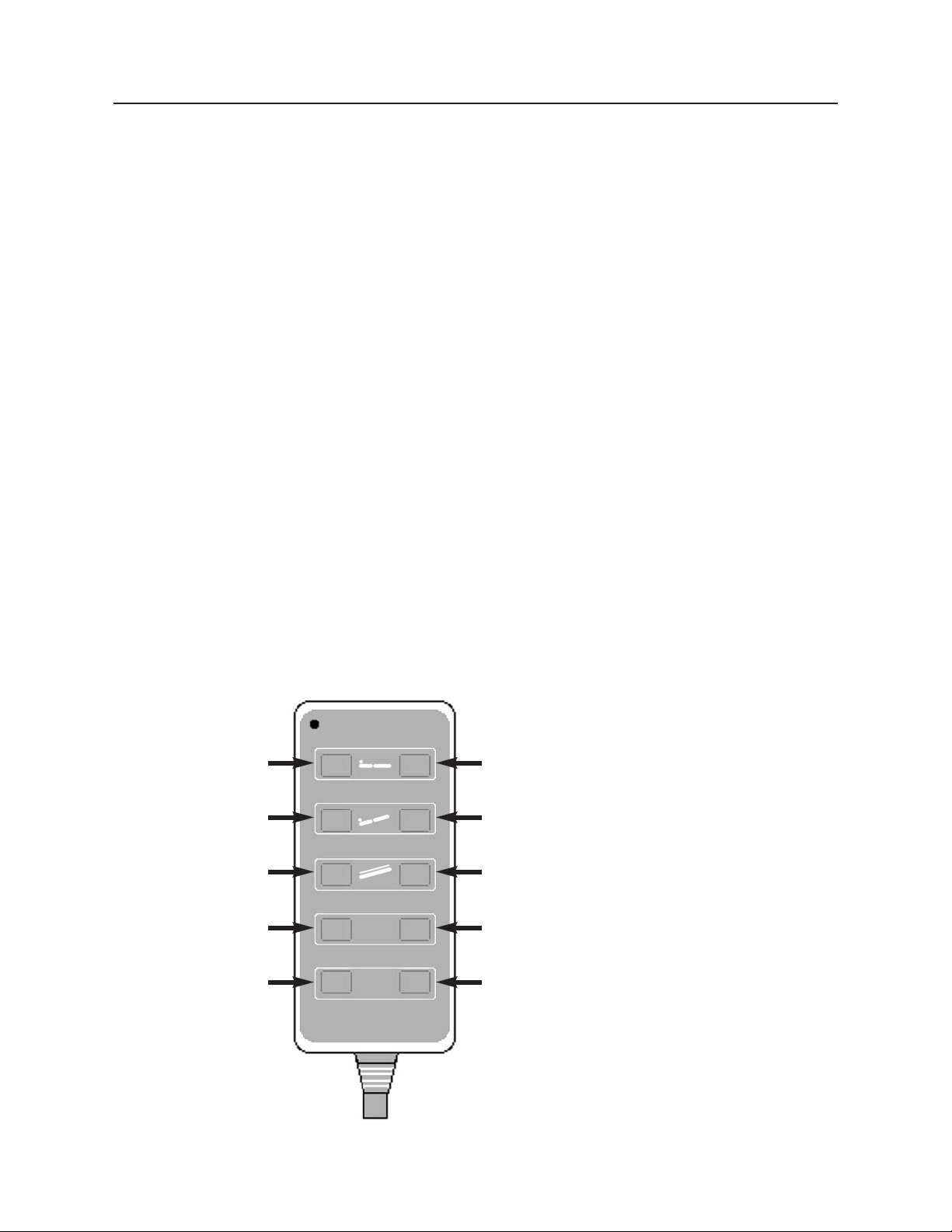
Hand Wand Procedure - Memory Positioning Instructions
1 Initialize all of the actuators by running each actua-
tor (one at a time) to it’s fully retracted position.
This would be; lower the height actuator all the way
down, position the lateral tilt actuator to level and
place the bed in reverse Trendelenburg position (the
Trendelenburg actuator is fully retracted in this
position).
2 Using the buttons on the hand wand, utilizing as
many of the actuator motors as necessary but running only one actuator at a time, place the bed in the
desired position for the first memory selection.
When you are satisfied with the position attained,
press and hold-down the [P 1] and [M] buttons at the
same time. An audible tone will be produced by the
actuator control box when the memory position is
stored.
Your handwand will contain appropriate functions for the bed shipped.
MEDICAL POSITIONING
P 3 M
P 1
P 2
BED UP
BED DOWN
LATERAL TILT UP
REVERSE
TRENDELENBURG
MEMORY POSITION 3
MEMORY POSITION 1
LATERAL TILT
DOWN
TRENDELENBURG
MEMORY SET BUTTON
MEMORY POSITION 2
(Handwand will contain positions according to the functions of the bed received.)
Figure 3
Page 13
I - 11
Hand Wand Procedure - Memory Positioning Instructions (cont.)
Step Action
3 Repeat step 2 for memory positions 2 and 3, using
the [P 2] button for memory position 2 and the [P 3]
button for memory position 3.
Step
Action
4 To change any of the stored memory positions,
repeat steps 1 and 2 for the position you wish to 3.
change. It is not necessary to reprogram all of the
positions in order to change only one or two of
them.
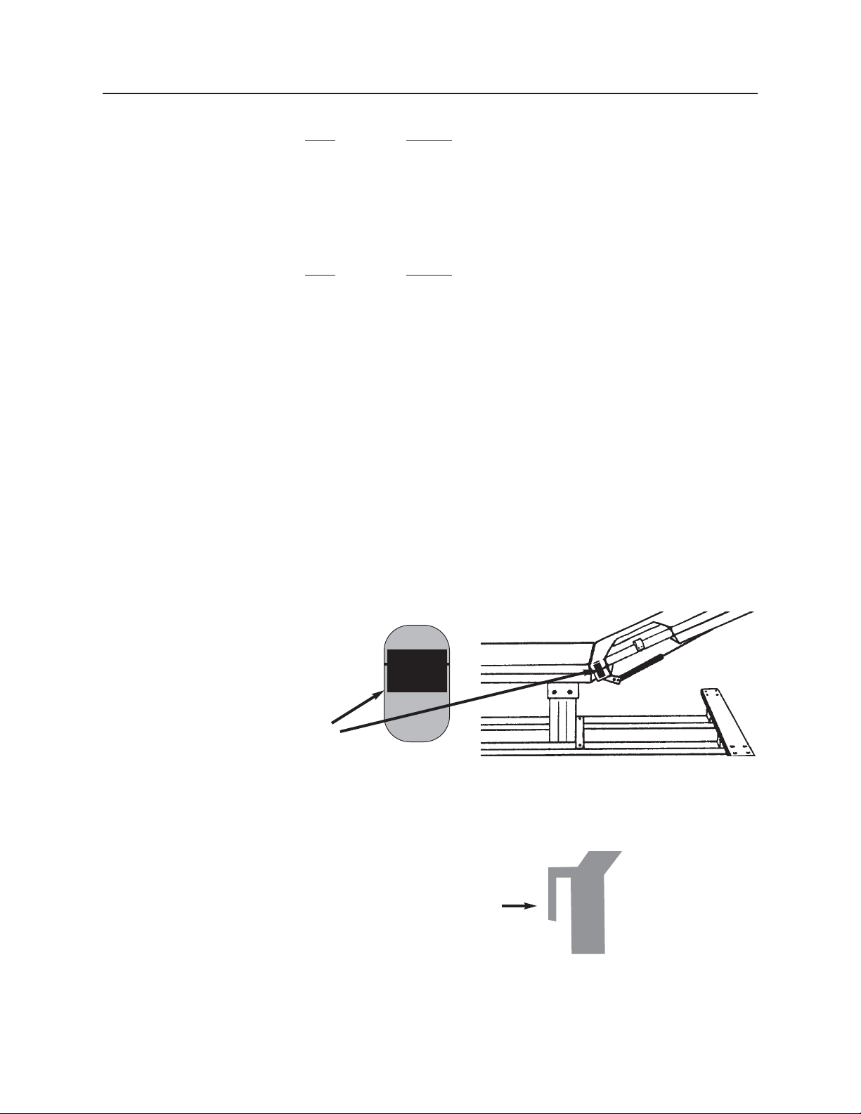
Figure 5
Figure 4
Side View of
Hand Wand
Hand Wand Hook
(hook over safety rail)
Back View of
Hand Wand
Velcro
Beds with safety rails - The hand wand has a hook installed on the
back which is designed to hang on the safety rail. (See Figure 5)
The hand wand attaches to the bed in one of the two (2) following
ways: Beds without safety rails - The hand wand has a Velcro strip
on the back and the bed has Velcro on the side. (See Figure 4)
Page 14
I - 12
Drop Section (Imaging Window Only)
The drop section is designed to be opened or closed easily with one
hand. Do not place other hand within the drop section area dur-
ing operation.
Step
Action
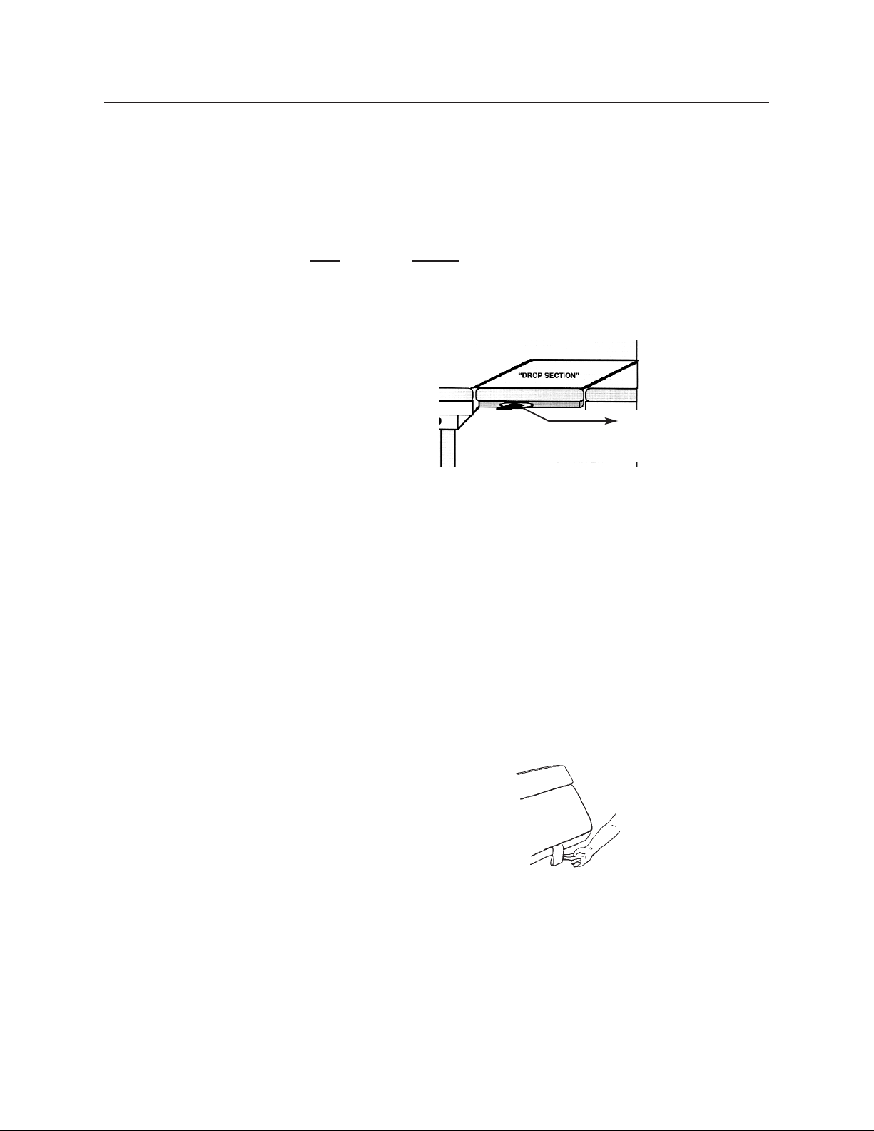
1 To open the drop section, locate the metal handle
mounted on the bottom of the drop section at the
front edge. (See Figure 6)
2 Pulling the handle outward, from under the drop
section, will release the latch mechanism and allow
the drop section to swing open. Do not abruptly
yank or jerk on handle, it is designed to work with a
smooth, steady pull.
3 To close the drop section, grasp the pull tab (fabric
loop) located on the front edge of the drop section
and lift the drop section smoothly until it is securely in the full, upright and locked position. (See
Figure 7)
4 It is not necessary to "slam" the drop section closed.
Slamming the drop section closed will startle the
patient and may result in damage to the mechanism.
After closing, always lift up on the drop section to
assure that is totally locked before patient entry or
exit.
Figure 6
Figure 7
Move Release Lever
Page 15
I - 13
Dual Drop Sections
The Imaging Window Drop Section and the Sonographer’s Dual
Entry Drop Section are designed to be opened or closed easily with
one hand. The Imaging Window Drop Section may also be opened
remotely by using the remote release handle conveniently located
adjacent to the Sonographer’s Dual Entry Drop Section. The
Sonographer’s Dual Entry Drop Section also functions as a back
support for the patient. Follow Steps 1 and 2 for manual operation
of either drop section, proceed to Step 3 for remote operation of the
Imaging Window Drop Section and proceed to the “Dual Drop
Section Patient Support” section for instructions on positioning the
Drop Section in upright positions. Do not place hands within the
drop section area during operation.
Step
Action
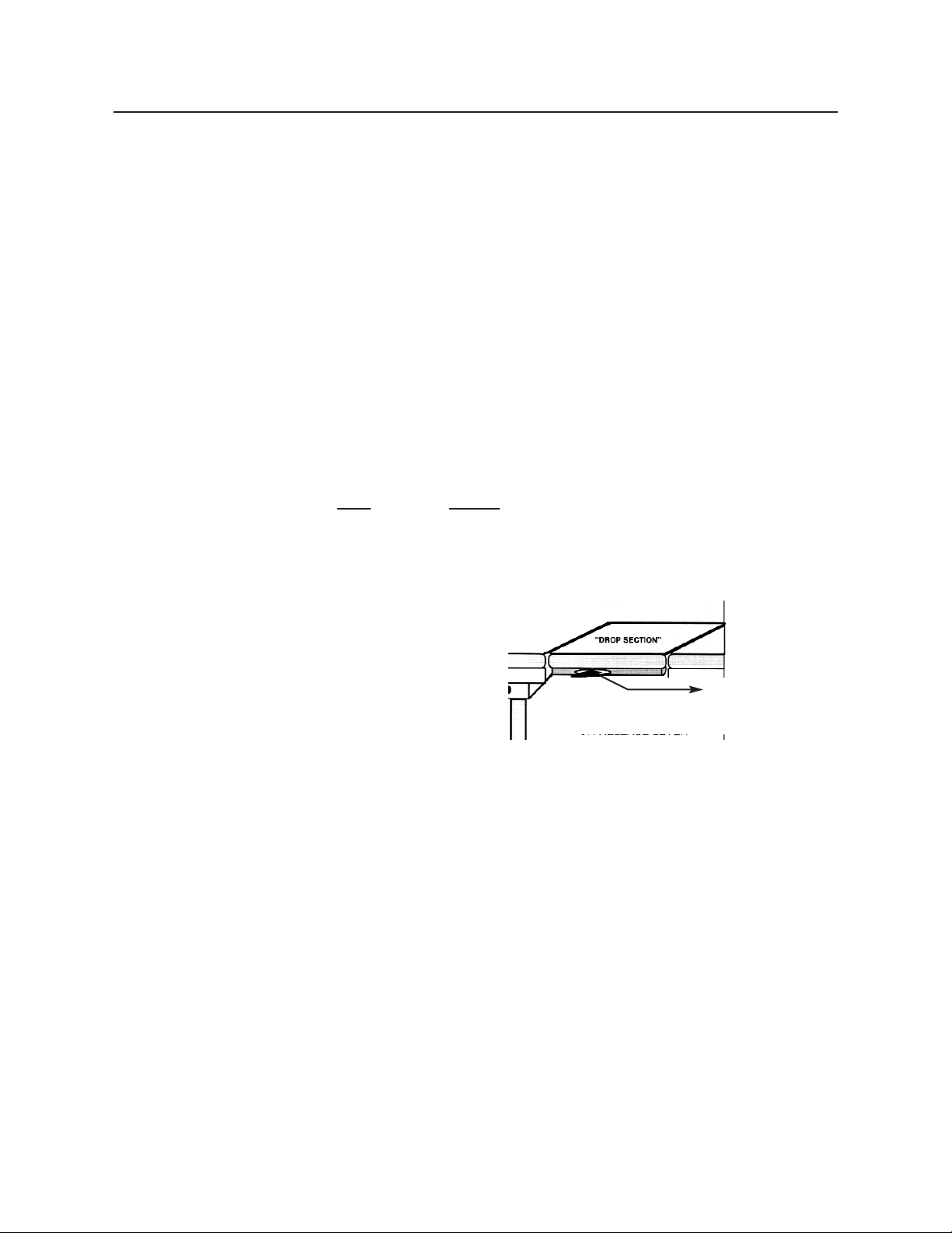
1 To open the drop section, locate the handle mount-
ed on the bottom of the drop section at the front
edge. (See Figure 8)
2 Pulling the handle outward, from under the drop
section, will release the latch mechanism and allow
the drop section to swing open. Do not abruptly
yank or jerk on handle, it is designed to work with a
smooth, steady pull.
To close either drop section, proceed to Step 4.
Figure 8
Move Release Lever
Page 16
I - 14
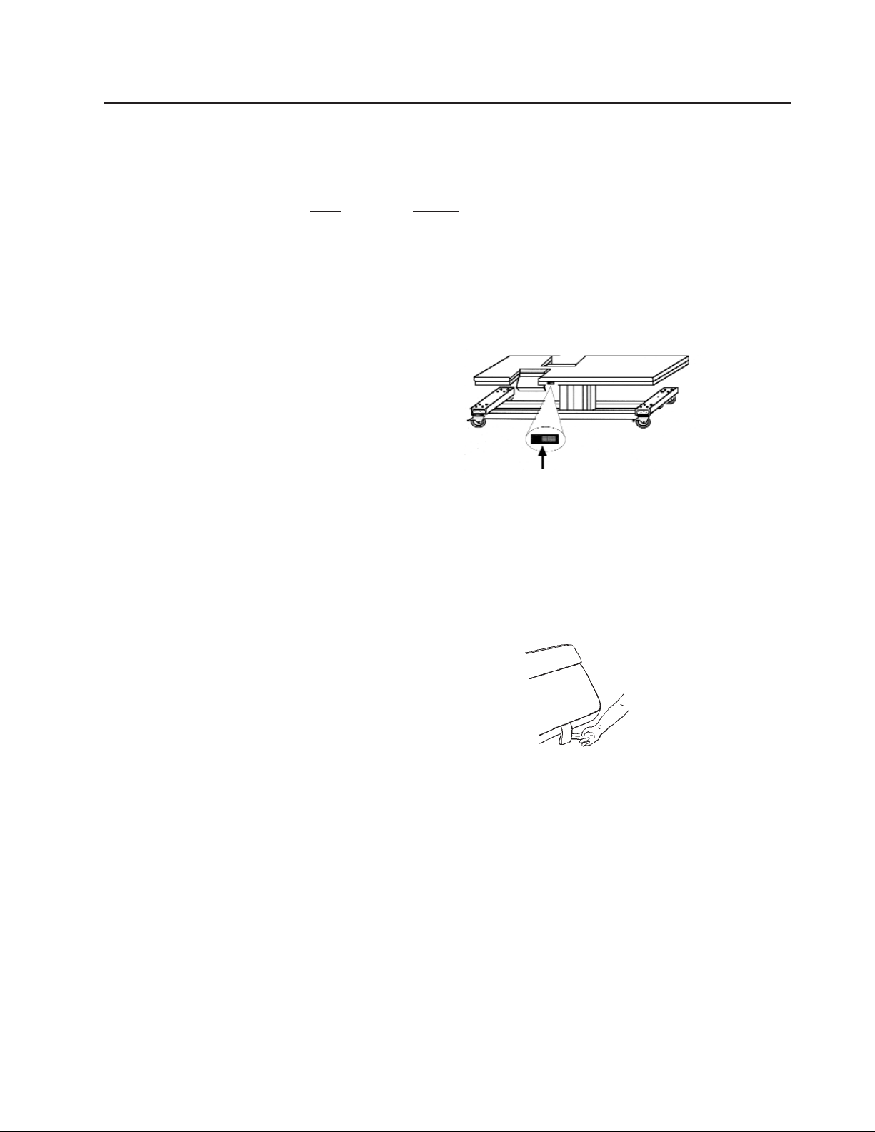
Remote Drop Section Operation
Begin here for instructions on how to operate the remote release for the Imaging Window Drop
Section.
Step Action
3 To use the remote release, position the patient in left
lateral decubitus position, pull out on the lever handle
far enough to allow the Imaging Window Drop Section
to open. You can accomplish this step while seated.
(See Figure 9)
4 To close either of the drop sections, grasp the pull-tab
(fabric loop), located on the front of the each Drop
Section and lift the Drop Section smoothly until it is
securely in the full, upright and locked position. (See
Figure 10)
5 It is not necessary to “slam” the drop section closed.
Slamming the Imaging Drop Section closed will startle
the patient and may result in damage to the mechanism.
Slamming the Sonographers Drop Section will cause it
to over travel the latches. After closing the Imaging
Drop Section, always lift up to assure that it is totally
locked before patient or personal entry or exit.
6 The drop section latches are adjustable. In order for the
Imaging Window Drop Section and the Sonographer’s
Entry Dual Drop Section to continue to operate correctly, you must inspect annually.
Figure 10
Figure 9
Page 17

I - 15
Dual Drop Section Patient Support
The Sonographer’s Dual Entry Drop Section may be lowered (as previously described), enabling
correct posture for the right handed Sonographer or raised to provide support and proper positioning for the patient. When raised the Drop Section may be locked into one of two different positions. To raise and return to level, please perform the following:
Step
Action
1 Lift the Drop Section until it engages in the first locked
position. If a steeper angle is desired, momentarily pull
out on the Drop Section mechanism release handle at
the front edge of the drop section (the same handle you
use to lower the drop section) and pull the Drop Section
until it engages the second locked position.
2 To lower the Drop Section back to level, pull out on the
Drop Section mechanism release handle at the front
edge of the drop section (the same handle) and let the
Drop Section down until it engages the mechanism
receivers.
Page 18
I - 16
Sonographers Drop Section Extension
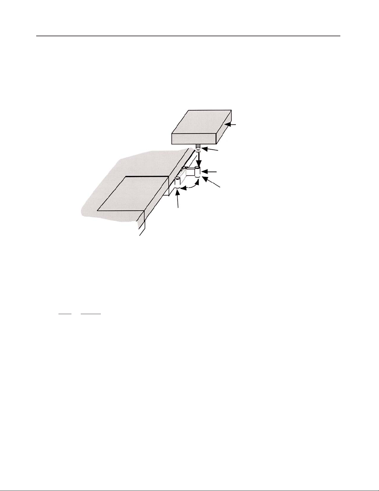
The Sonographer Drop Section Extension is designed to increase the usable sitting area and
comfort for the sonographer. This addition improves posture and body position for the right
handed scanning sonographer. The extension is removable and mounts into a support
bracket (The extension is shipped with the dual drop section bed but packaged separately)
The Sonographer Extension Support Bracket is mounted to the side of the bed a few inches
away from the Sonographers Drop Section. It has been placed in the Shipping/Storage
position.
Step
Action
1 Rotate the Support Bracket to the Use Position (Straight out of the bed side) (See
Figure 11)
2 Insert the Pilot Tube into the Support Tube as shown.
Figure 11
UPHOLSTERY PAD
PILOT TUBE
USE POSITION
SUPPORT
BRACKET
TRANSPORT
POSITION
Page 19
I - 17
Non-Pinch Closure
The Non-Pinch Closure Flaps, located at the back edge of both the
Imaging Window Drop Section, and the Sonographer’s Entry Drop
Section prevent the patient from being pinched when either drop
section is closed after imaging.
Examine the Non-Pinch Closure Flap with the drop section open
and closed. The flap attaches to the bed surface with hook and loop
tape that has been permanently attached to the surface.
The drop section should not be operated without the non-pinch closure flap in place.
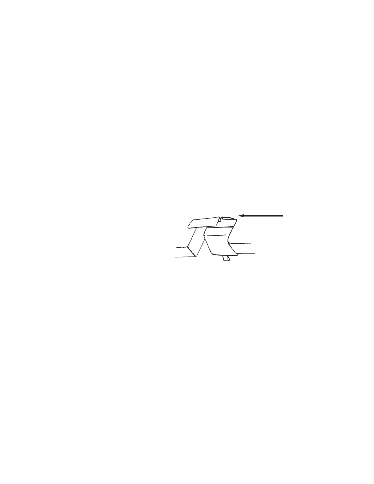
The flap is attached to the bed with Velcro tape and can easily be
adjusted whenever necessary. (See Figure 12)
Occasionally the flap may become bent or creased. When that
occurs, remove the flap from the bed surface by separating the
Velcro tapes. Next, return the flap back to original shape by bending it farther in the opposite direction of the bend or crease and
allowing it to spring back to flat.
Should the flap require replacement, you may order one through
Medical Positioning, Inc. at 1-800-593-ECHO (3246).
Figure 12
Flap
Page 20
I - 18
Caster Use Procedure (for beds with individual locking casters)
The casters installed on your Echo™Bed are total locking casters.
When in the locked position, the caster is prevented from both
rolling and swiveling. Before beginning any procedure involving a
patient, insure the casters are in the locked position.
Step
Action
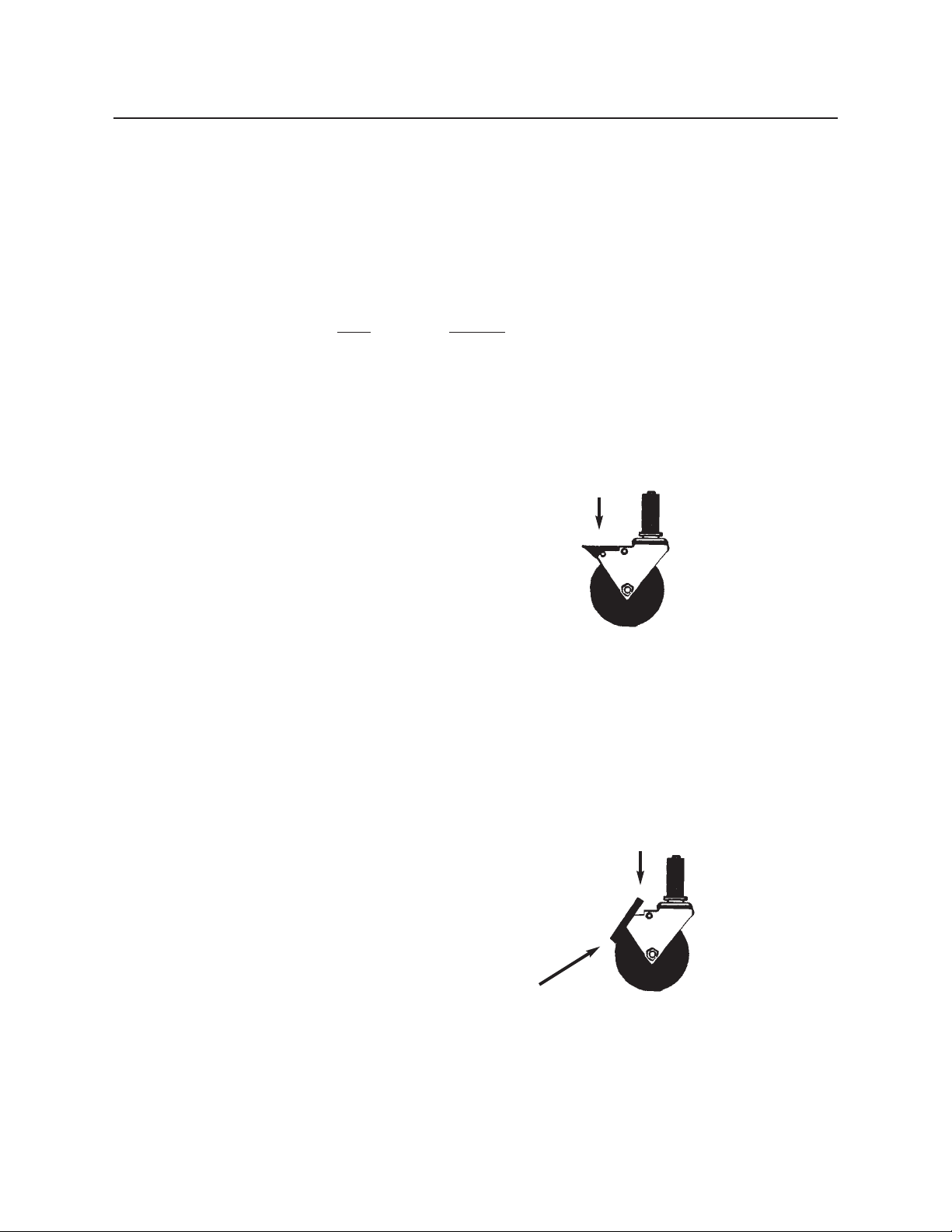
1 To lock the caster, step down on the outermost edge
of the black locking tab located at the top of the caster wheel. (See Figure 13)
2 To unlock the caster step down on the top, inner-
most edge of the locking tab or lift up on the outermost edge of the tab.(See Figure 14)
To lock
Figure 13
To release
Figure 14
Page 21
I - 19
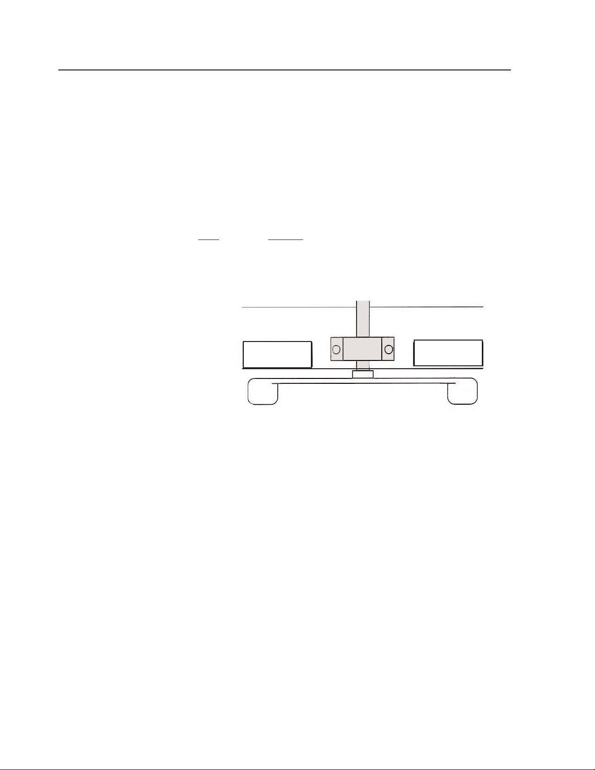
Caster Use Procedure - (for models with single pedal braking)
The casters installed on your Echo™Bed / Echo™Bed Dual are
controlled by one single pedal located in the center of the base
frame. When in the locked position, the caster is prevented from
both rolling and swiveling. Before beginning any procedure
involving a patient, insure the casters are in the locked position.
Step
Action
1 To lock casters, press down in the lock position.
This will simultaneously lock all four casters in both
the swivel and roll modes.(See Figure 15)
2 To allow all 4 casters to swivel and roll, allow foot
pedal to be in the center (horizontal) position.(See
Figure 15)
3 To steer the bed, press down in the steer position
and this will simultaneously lock the swivel of the
foot-end casters while allowing the head end casters
to swivel for steering. (See Figure 15)
DOWN TO
LOCK
CENTER FOR FREE WHEELING
DOWN TO
STEER
STEER FROM HEAD END
Figure 15
Page 22
I - 20
Remote Release Maintenance
The Echo™Bed Dual has a remote release drop section for righthanded scanners. The remote release mechanism may require
minor adjusting after use. If you find that the remote release is not
working as it should, please proceed with these instructions.
Tool Required
Phillips Head Screwdriver
Procedure
This procedure is performed with the drop section closed. Located
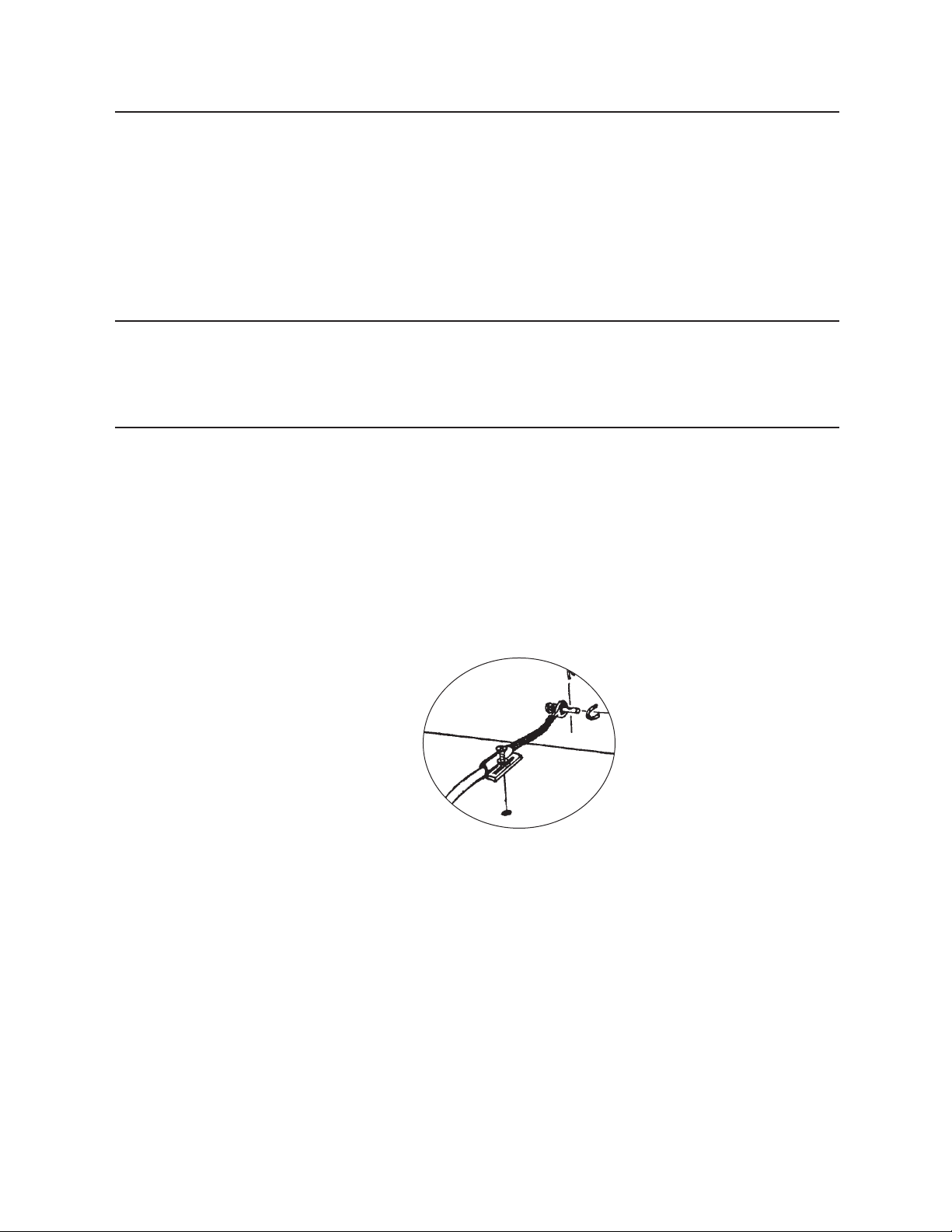
under the imaging window drop section is the control cable for the
remote release handle. (See Figure 16) The cable is equipped with
an adjustable mounting tab. Should it be necessary, adjustment is
performed in the following manner.
(continued)
Figure 16
View of Remote Release Cable Installation
Page 23
I - 21
Remote Release Maintenance Procedure (cont.)
The following may help you determine whether you need to tighten the cable or loosen the
cable.
Tighten the cable: When opening the imaging window using the
remote release, the drop section does not respond properly. In this
event, follow steps 1, 2, and 4.
Loosen the cable: When closing the drop section after use, one or
both sides of the drop section do not fully engage or latch securely.
In this event, follow steps 1, 3, and 4.
Step
Action
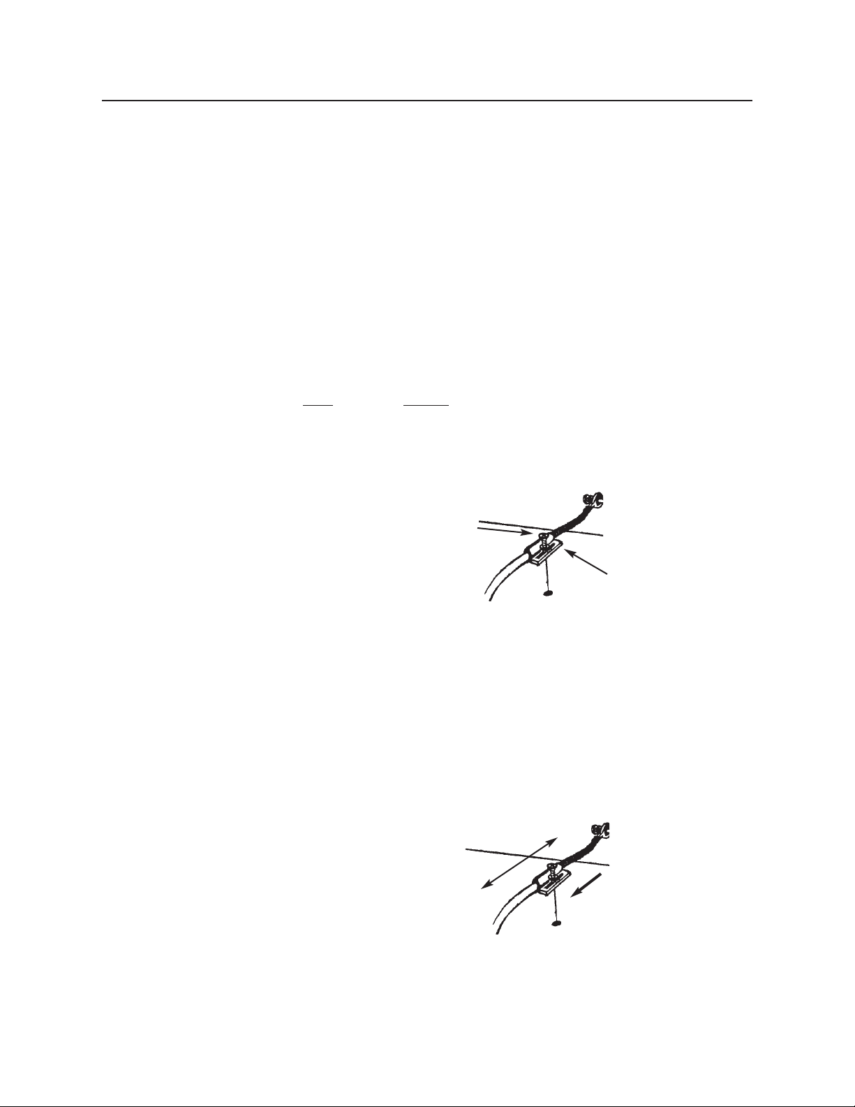
1 Locate and loosen the Phillips Head screw that
holds the mounting tab in place. (See Figure 17)
2 To tighten the cable, (take up the slack in the cable
) slide the mounting tab towards the center of the
bed. (See Figure 18)
(continued)
Figure 18
Loosen
Tighten
Figure 17
Phillips Head screw
Mounting Tab
Page 24
I - 22
Remote Release Maintenance Procedure (cont.)
Be careful when tightening the cable, (moving the mounting tab).
Only tighten enough to take-up slack in the cable. Taking up too
much slack in the cable may prevent the drop section latch from
fully engaging.
Step
Action
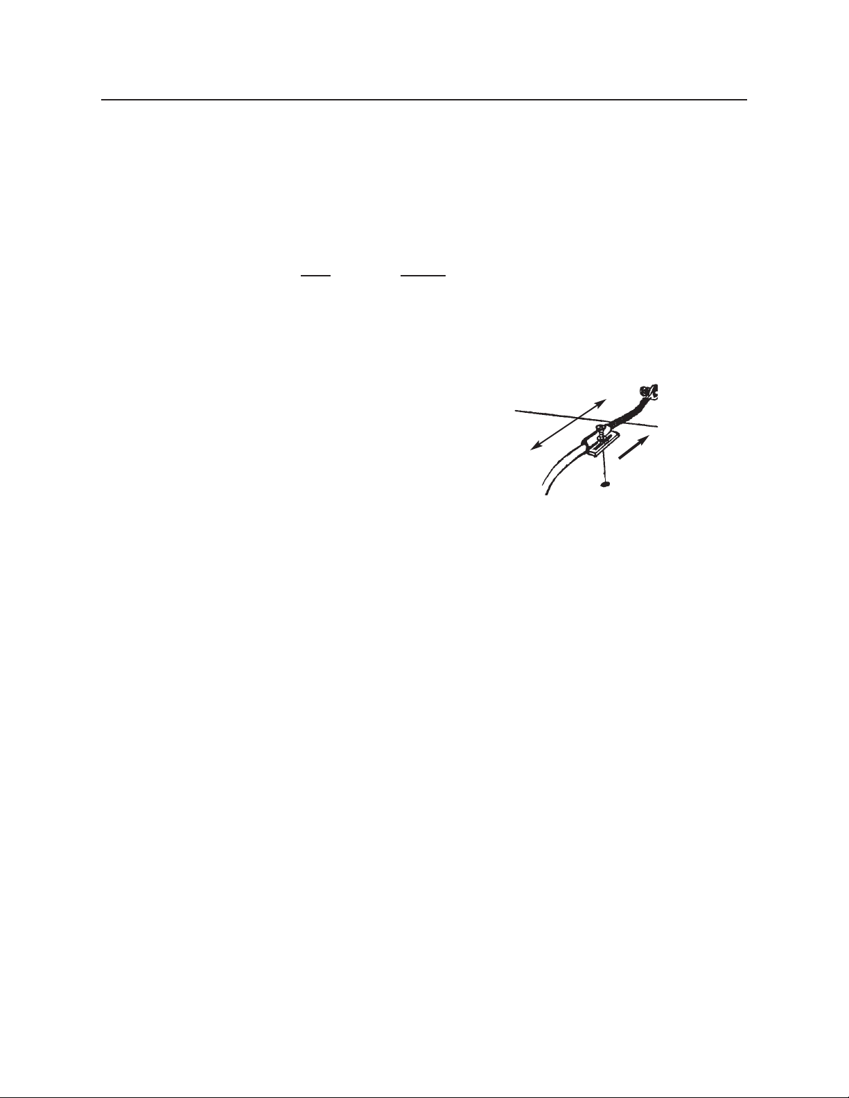
3 To loosen the cable, (increase slack to allow more
secure closure) slide the mounting tab away from
the center of the bed. (See Figure 19)
4 Re-tighten the Phillips head screw in the mounting
tab to lock-in the adjustment.
Figure 19
Loosen
Tighten
Page 25
I - 23
All Ways™Echo™Bed (3 Drop Sections)
In addition to single and dual drop section operation previously described, the All Ways™Echo™
Bed incorporates a third drop section and a pivotal devise allowing both right and left handed
sonographers to use the bed with little or no repositioning of the ultrasound equipment.
In This Section
You will be instructed on how to engage and disengage the pivotal mechanism and available
bed/sonographer position options.
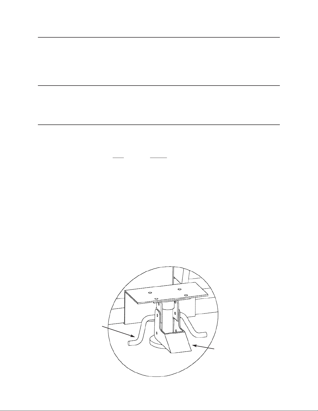
Pivotal Mechanism
The pivotal mechanism is located next to the pedestal column of the bed.
Step
Action
1 Before engaging the mechanism, place the bed and
the ultrasound equipment in position for either left
or right handed sonography.
2 When positioned, engage by placing your foot on
the flat metal plate in the center of the pivotal mechanism and step down firmly. (See Figure 20)
3 To disengage, place your foot on either of the round
brackets projecting form the sides of the center, flat
plate and step down.
To engage, place foot
on flat metal plate and
press down firmly.
To disengage, place
foot on round brackets
and step down.
Figure 20
Page 26
I - 24
All Ways™Echo™Bed Use
The patented 3 drop section and pivotal mechanism design of the All
Ways™Echo™Bed allows utilization of ultrasound equipment and
examination rooms by both left and right handed sonographers with a
minimum of equipment repositioning. See below for recommended
techniques.
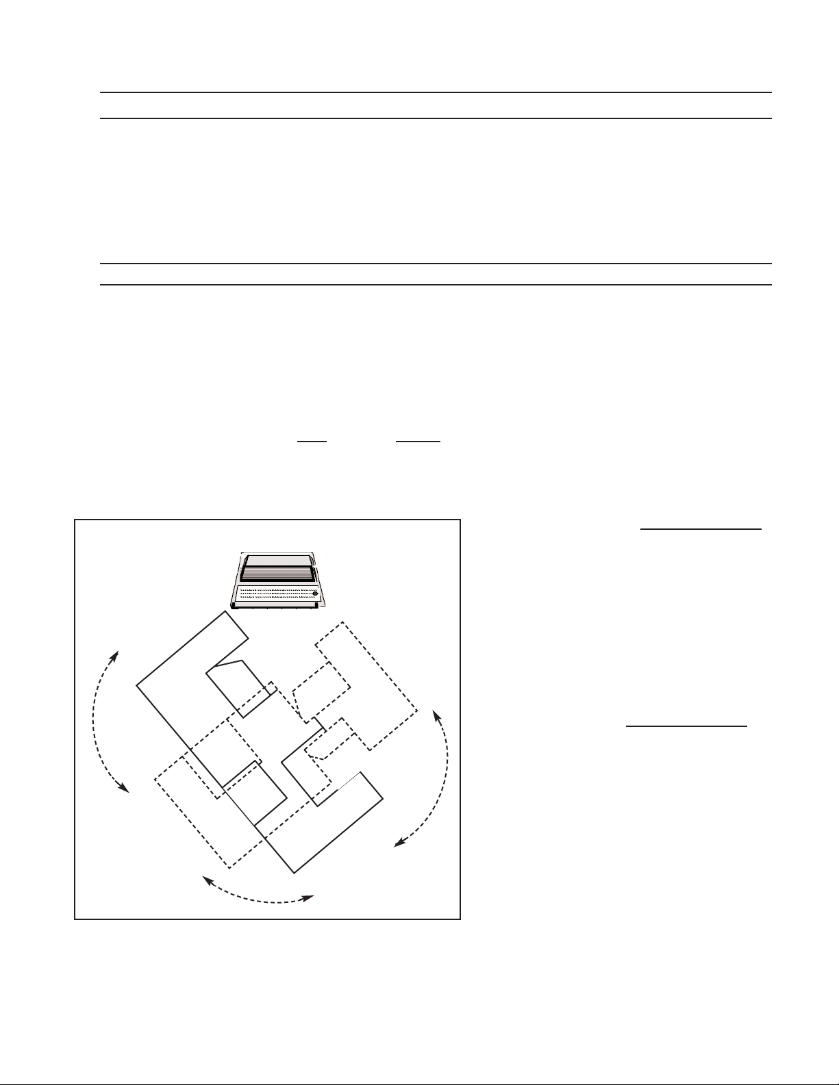
Bed Rotation
This technique allows you to leave the ultra-sound equipment in a singular position and rotate the bet to achieve sonographer access.
When the bed has been positioned for right or left handed orientation
and you desire to change to the opposite orientation:
Step
Action
1 Engage the pivotal mechanism as described in the
previous section.
2 Unlock the brakes on ALL 4 CASTERS.
3 Rotate the end of the bed closest to the
ultrasound machine away from the ultrasound machine. The bed will rotate around
the pivotal mechanism until the opposite end
of the bed arrives next to the ultrasound
machine.(See Figure 21)
4. Lock the brakes on ALL 4 CASTERS
.
For ultra-sound repositioning for elongated
rooms see next page.
Ultra-Sound Unit Remains Stationary
Square Rooms
BED PIVOTS ON STATIONARY PIVOT
POINT FOR RIGHT HANDED
SONOGRAPHY
Figure 21
Page 27
I - 25
Ultra-Sound Rotation
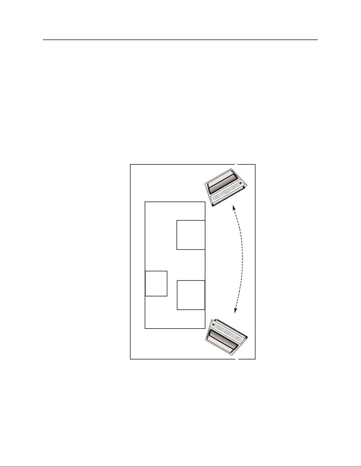
Utilization of the multiple drop section characteristics of the AllWays™Echo™Bed for right or
left handed orientation can be achieved by rotating the bed as previously described or, where
space availability will not permit, by repositioning the ultrasound equipment as shown in Figure
22 .
If this technique is to be used often, careful routing of the electrical cables at time of installation will facilitate quick and easy equipment movement.
Elongated Rooms
LIMITED MOVEMENT OF
ULTRASOUND UNIT
ALLOWS LEFT/RIGHT
HANDED SONOGRAPHY
Figure 22
Page 28

I - 26
Cleaning Instructions
Please note that substances such as imaging gels and alcohol will not damage the vinyl surface when immediately removed. Studies have shown that exposure for longer than a few
minutes can damage the top coat and will eventually discolor vinyl.
The painted metal and plastic surfaces can be cleaned with normal cleaners and disinfectant.
Step
Action
1 Clean and/or disinfect with liquid cleaner of choice
being careful to follow label instructions provided
with cleaner. (Always test a small area first to determine suitability of solution.)
2 Wipe the surface clean with a wet cloth after apply-
ing cleaners and disinfectant to remove excess
residue build-up.
ALWAYS READ MANUFACTURERS INSTRUCTIONS AND
WARNINGS BEFORE USING ANY CLEANING PRODUCT OR
DISINFECTANT.
The vinyl upholstered surfaces can be cleaned in one of the following ways:
Step
Action
1 When caught quickly, most everyday stains like
grease, blood and black felt tip pens can be wiped
right off. Use mild soap and water. For more stubborn stains, a variety of concentrated and solvent
type cleansers may be used without damaging the
surface (including alcohol, naphtha and bleach), as
long as they are thoroughly rinsed off with water.
(Abrasive household cleaners and steel wool should
be avoided - see the guide for complete care and
cleaning procedures.)
2 Everyday soil can usually be removed using a soft
cloth or sponge with mild soap and water. Spills
and accidents require immediate attention for best
results. In many cases, stains may be cleaned simply with warm water alone. If the stain is allowed to
set, more concentrated cleaners may be required.
Page 29

I - 27
Cleaning Instructions (cont.)
The following guide covers many of the most common staining agents. During independent
laboratory testing, many were allowed to stand for up to 40 hours with excellent cleaning
results.
Generally speaking, always start with the mildest cleaning agents first. Never use harsh powdered abrasive cleansers or steel wool. Products containing bleach, ammonia or alcohol
(Lysol
TM
) should be wiped from the surface with a wet cloth after use. Residue from these prod-
ucts will damage vinyl surfaces.
Step Action
1 Remove excess spill with damp cloth. Clean with
1:1 mix of Ivory™soap and water. Rinse with clean
water and dry.
2 Use straight application of concentrated cleaners
such as Formula 409™or Fantastik™Spray
Cleaner. Then wipe with clean cloth.
3 Use a 1:1 mix of ammonia and water or a 1:4 mix of
bleach and water. Rinse with clean water and dry.
4 Use straight application of naphtha (lighter fluid).
Rinse thoroughly with clean water and pat surface
dry. (see note below)
5 Use 1:1 mix of isopropyl alcohol and water. If stain
persists, use straight alcohol. Rinse thoroughly with
clean water pat surface dry. If stains remain, use a
1:1 mix of acetone and water. Rinse with clean
water and pat surface dry. (see note below)
Note: For cleaning that requires steps 4 or 5 - use a soft cotton
cloth saturated with the cleaning material, rub the stain in circles 10
times. Pat dry with another soft cotton cloth and check results.
This information is not a guarantee and does not relieve the user from the responsibility of the proper and safe use
of the product and all cleaning agents.
Formula 409™is a trademark of the Clorox Company.
Fantastik™Spray Cleaner is a trademark of the Texize Division of Dow Consumer Products, Inc.
Ivory™is a trademark of Procter and Gamble.
Lysol™is a trademark of Reckitt & Colman Inc.
Page 30

I - 28
Troubleshooting Guide
A “Troubleshooting Guide” is included to instruct you in the event of a malfunction. If you are expe-
riencing any of the following symptoms, this guide may help you quickly solve the problem. If, after
consulting this guide, you are still unable to operate your Echo
™Bed/ Echo™Bed Dual please contact
Medical Positioning, Inc. at 1-800-593-3246. Please have the following information ready when you
call:
1. Model Number or Name of Product
2. Date Received
3. Condition When Received
4. Symptom (or problem) Encountered & Result of Troubleshooting Procedure
No Actuator Function.
Actuator(s) Not Running.
Push power cord securely into receptacle.
Check power availability or plug unit into
another receptacle.
Inspect power availability light on control
box. (See Figure )
Inspect black plunger switch on power
strip and reset by pushing in (fig. 2).
Securely press end of hand wand power
cord into control box
Securely press end of actuator power cord
receiver (fig. 3). Inspect control box continuity light on handwand.
Power cord not plugged all the way in
wall receptacle.
Power outlet receptacle not supplying 120
VAC power.
The power cord may be separated from
the control box.
On supine ergometer units, the power
strip circuit protector may be tripped.
Hand wand not properly connected to
control box.
Actuator power cord not fully connected
to control box.
Symptom Probable Cause Suggestion
Page 31
I - 29
Illustrations
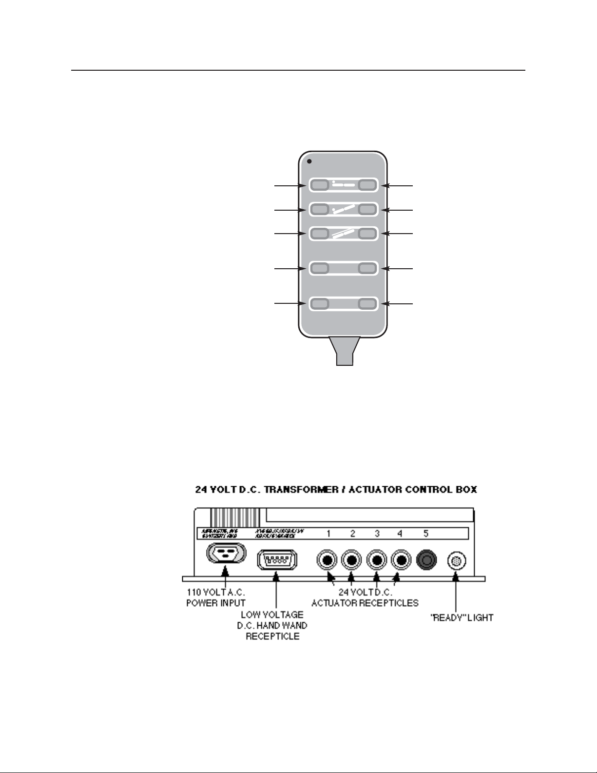
The following illustrations correspond with the instructions outlined in the “Troubleshooting Guide”.
Figure 23
Figure 24
P 3
M
P
2
P 1
Medical
Positioning
BED UP
REVERSE TRENDELENBURG
LATERAL TILT UP
MEMORY POSITION 1
MEMORY POSITION 3
BED DOWN
TRENDELENBURG
LATERAL TILT DOWN
MEMORY POSITION 2
MEMORY SET BUTTON
Page 32
I - 30
Warranty
WARR0700
US Patents 5,184,363; 5,461,739, 5,919,131; 5,950,262; Des. Patent # 347,691;
Other Patents Pending
Medical Positioning, Inc. 1717 Washington, Kansas City, MO 64108, (800) 593-3246 www.medicalpositioning.com
Hospital Models
Echo™Beds
1 year - Parts and labor
5 years - All electrical, mechanical and structural parts
This product is fully guaranteed against defects in material or workmanship, for the period indicated above commencing with receipt by the original end user. If a product fails due to a manufacturing defect, we will repair or authorize repairs to the product without charge or replace it at
our option.
We use only the finest materials available, but even these premium quality materials will not last
forever. Repairs due to normal wear, accident, improper care, or negligence, where we are not at
fault, will be performed for a reasonable charge. The warranty does not apply if the product has
been modified without the advance written permission of Medical Positioning, Inc. or if a Office
Model product is placed in an acute care facility.
Medical Positioning, Inc. makes no other warranty, either expressed or implied, with respect to
this product. Medical Positioning, Inc. specifically disclaims the implied warranties of merchantability and fitness for a particular purpose.
The remedies provided herein are customer's sole and exclusive remedies. In no event shall
Medical Positioning, Inc. be liable for any direct, indirect, special, incidental, or consequential
damages, whether based on contract, tort, or any other legal theory.
Product shall not be returned to Medical Positioning Inc. without prior written authorization from
Medical Positioning, Inc. If a product is returned without prior authorization, customer is responsible for all shipping charges and any applicable duties and/or taxes. When a repair is made on
site, (solely) at the request of the customer, the customer is responsible for all travel costs.
Page 33

II - 1
Parts List and Diagrams
Page 34

II - 2
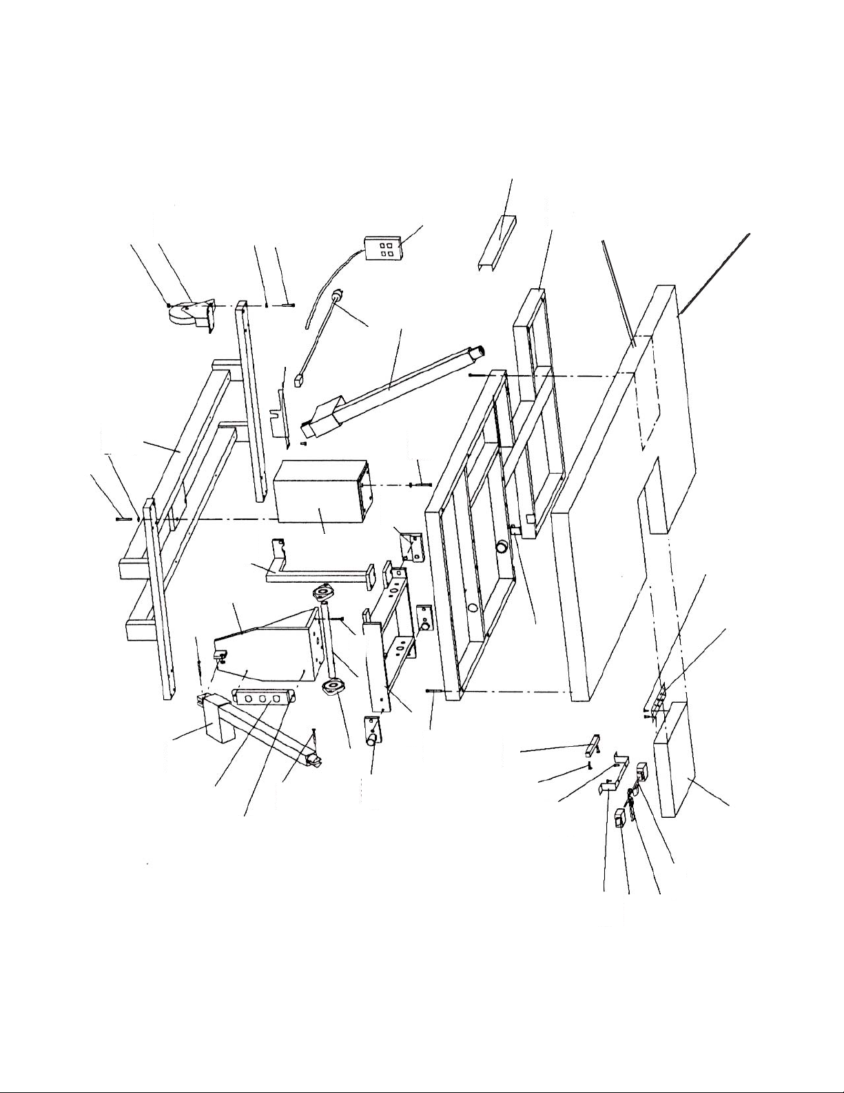
Parts List
Part # DESCRIPTION
10217 FRAME, BASE B1023-3
10218 FRAME, BED B1023-4
10219 PLATE, TOP B1023-5
10220 SHAFT, TRENDELENBURG B1023-6
10312 SPACER, COLUMN B1023-7
10332 BRACKET, PIVOT B1023-8
10221 FRAME, TRENDELENBURG B1023-9
10301 COLUMN, FIXED HEIGHT B1023-10
10222 BRACKET, LOWER LATERAL TILT B1023-11
10223 BRACKET, UPPER LATERAL TILT B1023-12
10224 BRACKET, BED B1023-13
10225 BRACKET, PEDESTAL B1023-14
10251 PROTECTOR, PLUG B1023-16
10307 TRAY, SMALL B1023-17
10308 TRAY, LARGE B1023-18
10253 FRAME, LATERAL TILT B1023-20
10302 BRACKET, TABLE B1023-23
10102 LINK, TRENDELENBURG B1023-99
10188 BOLT, HEX 1/4-20 X 3/4"
10026 BOLT, HEX 5/16-18 X 1 1/2"
10189 BOLT, HEX, 5/16-18 X 2" GRADE 8
10027 BOLT, HEX 3/8-16 X 1"
10343 BOLT, HEX, 3/8-16 X 1" GRADE 8
10190 BOLT, HEX, 3/8-16 X 2" GRADE 8
10191 BOLT, HEX, 3/8-16 X 3" GRADE 8
10192 BOLT,HEX, 1/2-13 X 2 1/2" GRADE 8
10193 BOLT, HEX, 10mm X 40mm
10194 BOLT, HEX, 10mm X 50mm
10195 BOLT, SHOULDER, 12mm X 35mm
10057 SCREW, PHILLIPS PAN HEAD, #8 X 3/4"
10116 NUT, NYLOCK 1/4-20
10028 NUT, HEX, 5/16-18
10196 NUT, HEX, 5/16-18 GRADE 8
10197 NUT, HEX, 3/8-16 GRADE 8
10198 NUT, HEX, 1/2-13 GRADE 8
10199 NUT, NYLOCK, 10mm
10255 WASHER, INTERNAL TOOTH, 5/16"
10254 WASHER, INTERNAL TOOTH, 3/8"
10140 WASHER, LOCK, 3/8"
10256 WASHER, INTERNAL TOOTH, 10mm
10205 WASHER, MACHINE BUSHING, 7/8 X 1 3/8-18 GA.
10056 WASHER, LOCK 1/2"
10238 BEARING, #GEZ014
10342 BEARING, FLANGE #EF1620-16
10240 COLLAR,SET SCREW, 7/8" ID
10284 GROMMET, CATAPILLAR #2692
10239 LEVEL, POCKET 5"
10245 POWER CORD 16/3 SJT
10278 POWER STRIP #ULHC4-15
10025 CASTER, PLATE #22-5156-45
10185 ACTUATOR, HT / LC 12XWDK2U-001
10215 ACTUATOR, LT / SGU014UDAK-400
10228 ACTUATOR, TB / SGU013UDAK-413
10216 WAND, CLASSICO-1 MOTOR #PHC1-130833
10279 WAND, CLASSICO-2 MOTOR H/LT #PHC2-130835
10229 WAND, CLASSICO-2 MOTOR H/TR #PHC2-130834
10239 WAND,CLASSICO-3 MOTOR H/T/L #PHC3-130836
Page 35
II - 3
10069
10070
10690DS
10441
10448
10216
10229
10239
10279
10026
10255
10237
10028
10217
10256
10193
10284
10251
10245
10215
10193
10256
10223
10190
10301
10185
10222
10219
10195
10228
10278
10171
10195
10220
10189
10366
10332
10190
10476
10221
10405
10200
10364
10171
10239
10341
10171
10069DS
10376
10351
10350
10348
10384H
10359
10036
10363
Page 36

II - 4
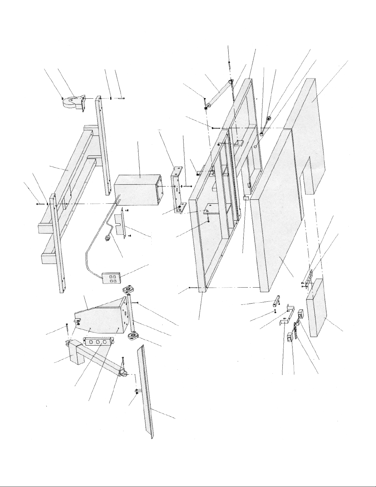
Parts List (EPS Bed with Fowler)
Part # DESCRIPTION
10344 FRAME,STATIONARY FOWLER-1
10345 FRAME,FOWLER FOWLER-2
10373 BRACKET,COLUMN FOWLER-3
10346 MOUNT,TRENDELENBURG FOWLER-4
10347 COVER,LATCH FOWLER-5
10348 STOP BAR,DROP SECTION FOWLER-8
10217 FRAME.BASE B1023-3,
10219 PLATE,TOP B1023-5
10220 SHAFT,TRENDELENBURG B1023-6
10251 PROTECTOR,PLUG B1023-16
10360 BOLT, HEX 1/4-20 X 3"
10405 BOLT, HEX 1/4-20 X1"
10026 BOLT, HEX 5/16-18 X 1 1/2"
10189 BOLT, HEX 5/16-18 X 2" GRADE 8
10190 BOLT, HEX 3/8-16 X 2" GRADE 8
10359 BOLT, MACHINE 10/24 X 1"
10193 BOLT, HEX 10mm X 40mm
10195 BOLT, SHOULDER 12mm X 35mm
10430 BOLT, HEX 7/16 X 1 3/4, GR 8
10369 NUT, PUSH 3/8" (MCMASTER #94803A031)
10361 NUT, TEE 10/24 X 5/8"
10362 NUT, TEE 1/4-20 X 5/8"
10028 NUT, HEX 5/16-18
10196 NUT, HEX 5/16-18, GRADE 8
10197 NUT, HEX 3/8-16, GRADE 8
10199 NUT, NYLOCK 10mm
10165 NUT, HEX 1/4-20
10381 NUT, COUPLING 1/4-28
10057 SCREW, PHILLIPS PAN HEAD #8 X 3/4"
10036 WASHER, FLAT #10
10363 WASHER, LOCK #10
10200 WASHER, FLAT 1/4"
10364 WASHER, LOCK 1/4"
10140 WASHER, LOCK 3/8"
10255 WASHER, INTERNAL TOOTH 5/16"
10256 WASHER, INTERNAL TOOTH 10mm
10203 WASHER, FLAT 1/2"
10254 WASHER, INTERNAL TOOTH 3/8"
10201 WASHER, FLAT 5/16"
10365 BEARING, NYLON FLANGE 3/4" O.D.
10366 BEARING, FLANGED PILLOW BLOCK #5968K44
10330 GAS SPRING, LOCKING -800N #028-00147
10331 RELEASE MECHANISM,GAS SPRING #021-00075
10350 LATCH, #AE3/22388
10351 HANDLE, #PIN100
10376 CHAIN, #10 STAINLESS STEEL BEAD
40019 SPRING, LATCH #C28S/C28C
10377 COUPLING, CHAIN END
10354 KNOB, 1 3/8"DIA. X 1/4-20 THREAD #85221
10353 SWIVEL, CONTROL - MC MASTER #6058K13
10382 ROD, THREADED 1/4-28
10123 TUBING,CLEAR PLASTIC 3/8 ID
10284 GROMET, CATAPILLAR #2692
10239 LEVEL, 5"POCKET
10278 POWERSTRIP, #ULHC4-15
10237 CASTER, PLATE
10245 POWER CORD, 16/3 SJT
10185 ACTUATOR, HT/ #LC12XWDK2U-001
10228 ACTUATOR, TB #SGU013UDAK-413
10216 HANDSWITCH, PNEUMATIC H
10229 HANDSWITCH, PNEUMATIC H/TR
10370 WOOD KIT
10384 UPHOLSTERY KIT
Page 37
II - 5
10384US
10354
10365
10344
10353
10381
10123
10382
10331
10201
10189
10330
10360
10201
10189
10255
10026
10028
10237
10193
10256
10217
10028
10193
10256
10373
10185
10199
10195
10171
10278
10228
10195
10366
10220
10189
10190
10360
10200
10364
10229
10216
10284
10251
10197
10245
10219
10384H
10359
10036
10363
10347
10171
10239
10171
10405
10200
10364
10384LS
10348
10350
10351
10376
10384DS
10345
10346
Page 38
1
Collapsible Safety Rail Operation
Introduction
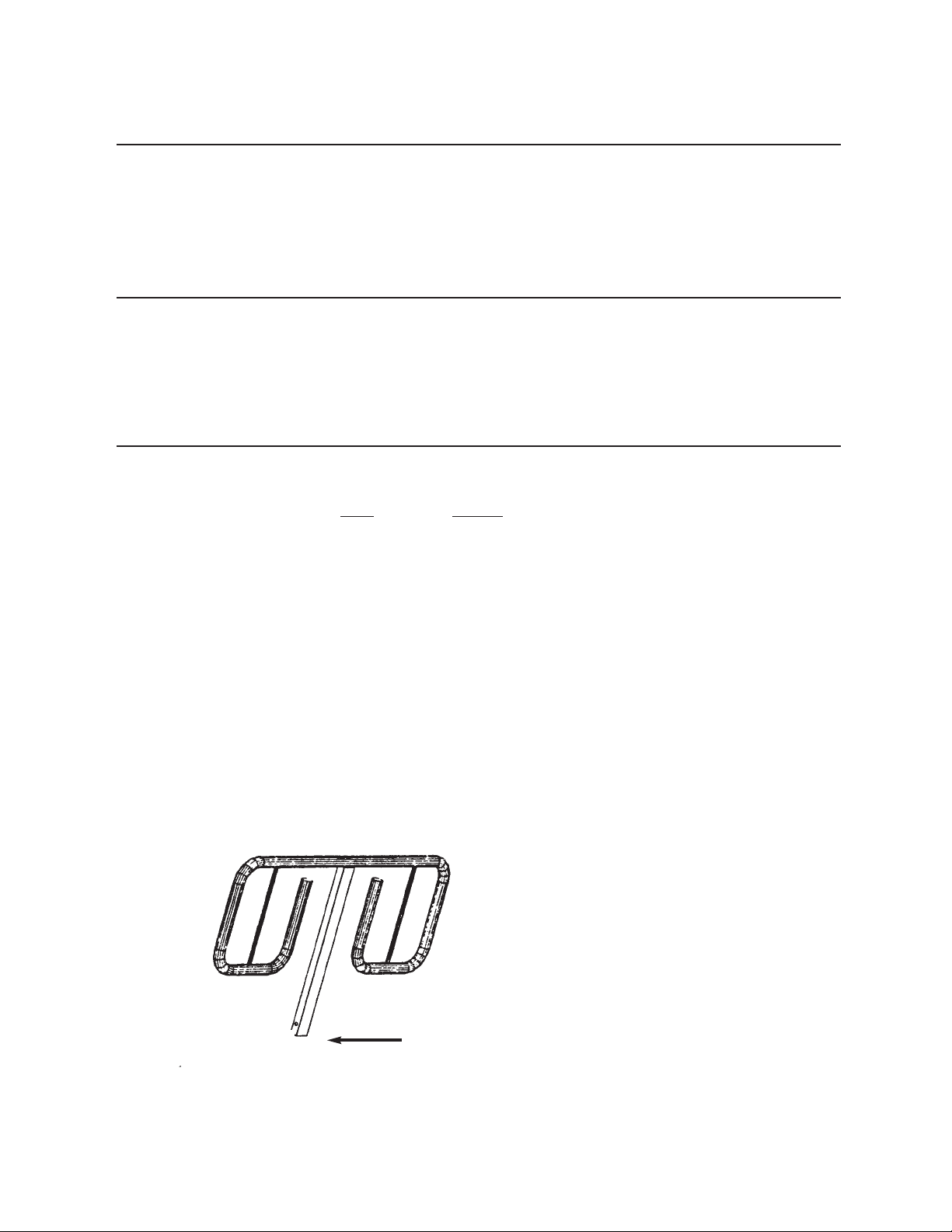
Collapsible Safety Rails are an accessory item that may have been
purchased on your Echo™Bed or may be installed at a later date.
In This Section
You will be instructed on how to operate the collapsible safety
rails.
Collapsible Safety Rail Operation Procedure
Step Action
1 To remove the safety rail, hold the safety rail with
one hand (to prevent it from dropping) while you
pull the release button with the other hand. (See
Figure 1)
2 To lower or replace the safety rail, pull the release
button, insert and lower the safety rail all the way
down. Let go of the release button.
3 To raise the rail, lift the safety rail until the locking
tab of the release button engages the locking hole in
the safety rail preventing it from further movement.
Figure 1
Release Button
(Pull)
Page 39
III - 2
Paper Roll Holder Installation
Introduction
The paper roll holder and cutter is an accessory item that may have
been purchased with your Echo™Bed or may be installed at a later
date.
In This Section
If the bought at time of purchase, the paper roll holder was preinstalled at the factory to insure proper fit, then removed to prevent
damage during shipment. You will be instructed on how to reinstall the paper roll holder.
Paper Roll Holder Installation
Tools Needed: 1 Philips Head Screwdriver
Step
Action
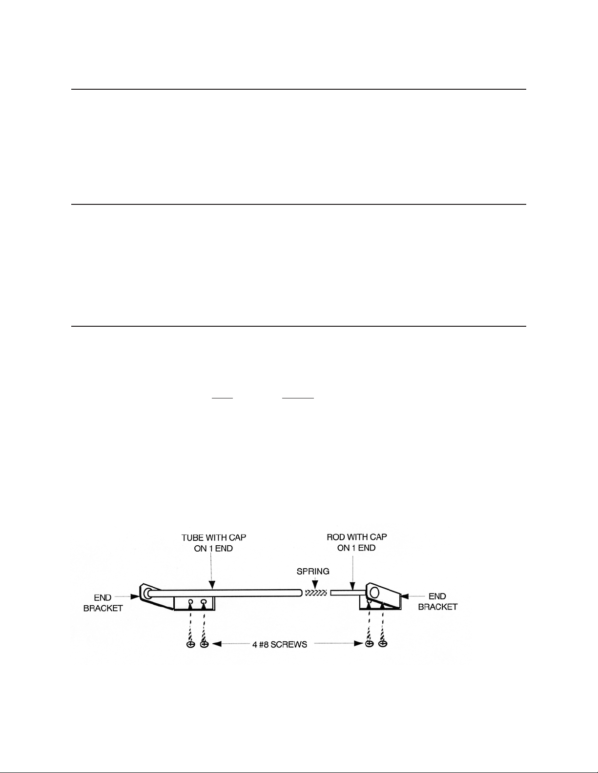
1 Install the paper roll holder at the head of the bed as
shown in Figure 2 , using the 4 (four) #8 screws pro-
vided. Carefully place the screws through the paper
roll holder mounting brackets and re-install into the
bed. Do not over tighten the mounting screws.
Over tightening may cause the threads to strip.
Figure 2
Page 40
III - 3
Pediatric / Geriatric Adapter Use
Introduction
The pediatric/geriatric adapter can be placed over the open "Drop
Section" imaging window to lessen the size of the opening when
imaging smaller patients. It should be removed when not in use.
In This Section
You will be instructed on how to properly place the Pediatric /
Geriatric Adapter.
Pediatric / Geriatric Adapter Use
In order to use the pediatric/geriatric adapter it is necessary to first remove the "Non-Pinch
Closure" flap.
Step
Action
1 Lower the Drop Section.
2 Remove the Non-Pinch Closure Flap by grasping
one side of the Flap and gently separating the hook
and loop attachment.
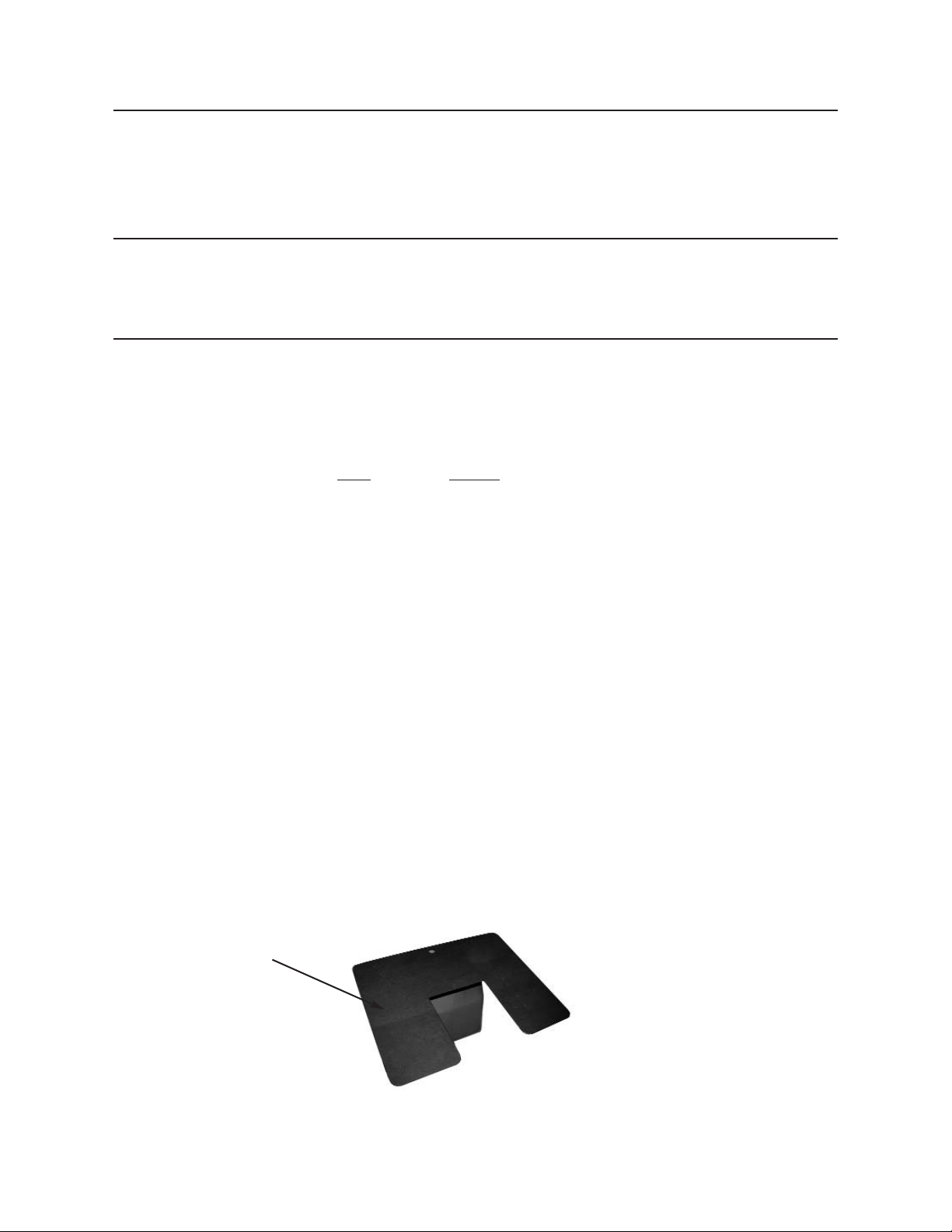
3 Position the adapter locator flanges within the imag-
ing area. (See Figure 3)
Important: When the adapter is not required, simply lift up and out
to remove. Replace the "Non-Pinch Closure" flap to insure
patient comfort and safety.
4 With the drop section lowered, align the top edge of
the non-pinch closure flap, (within the access cavi-
ty) with the top edge of the bed surface.
5 Press the hook and loop attachment strips together.
Figure 3
Locator Flange
Page 41
MEDICAL POSITIONING
Model
1200 – Fully upgradeable to all options
Height - 28 1/2”
1201 – Height Adjustable 24" - 34"
1223 – Height Adjustable 24" - 34" &
Trendelenburg/ rev. Tren. (±15°)
Echo™Bed Dual
Specifications for Models 1200, 1201, 1223
OPTIONS
• Leg supports
• Head supports
• Positioning SafeTwedges™
• 71 Optional vinyl colors
• Pediatric/Geriatric adapter
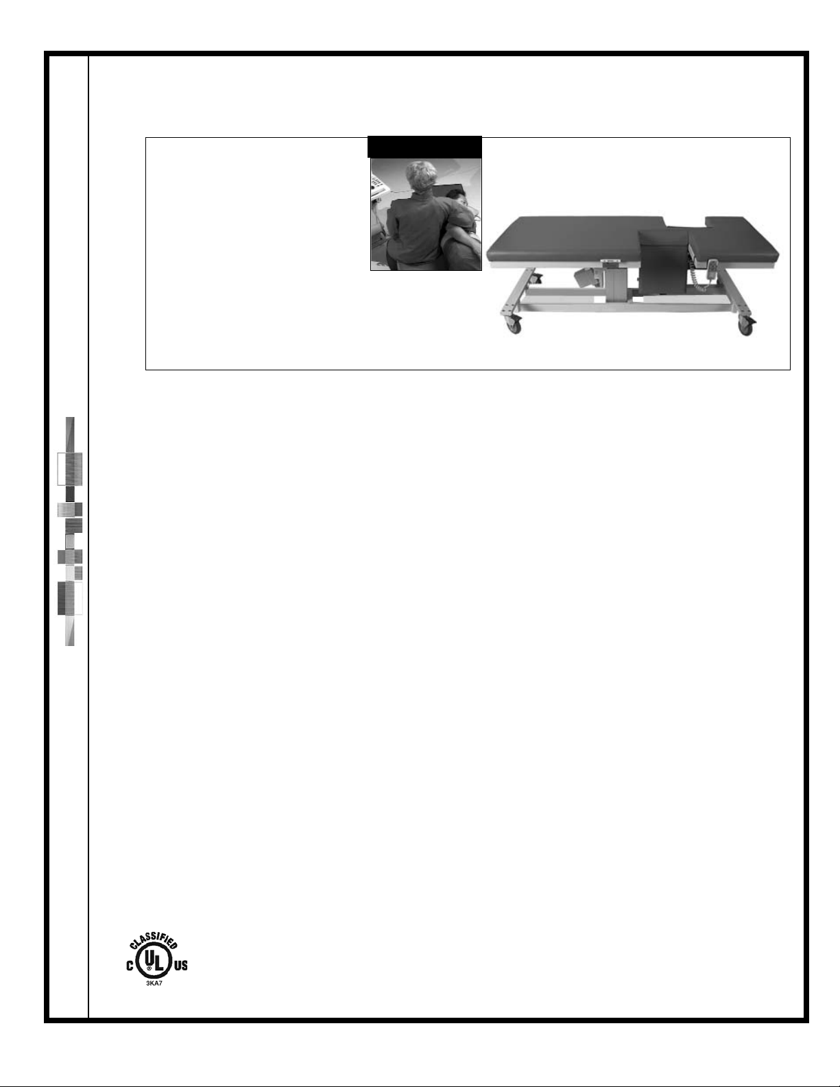
Model 1223 shown with storage trays
WARRANTY
5 Years - All electrical, mechanical and
structural parts
1 Year - Parts and labor
(see Warranty for complete details)
Optimal Posture
Standard
collapsible/removable
safety rails
EBSS0406
Medical Positioning, Inc. • 1717 Washington • Kansas City, Missouri 64108 • 800-593-ECHO(3246) • FAX (816) 474-7755 • www.medicalpositioning.com
HOSPITAL SPECIFIC
FEATURES
•
1,250 lb. Load capacity
•
500 lb. Lift capacity
•
Single pedal braking
• Single pedal steering
• 3 Position memory hand controller
•
2 Collapsible/Removable safety rails
• Underwriters Laboratory listed for hospital use
(UL 601, CSA & IEC 60601-1 Standards)
•
#817 SafeTwedge™
•
IV pole holder
•
Corner bumpers
•
6 Standard vinyl colors
•
Paper roll holder & cutter
•
Leg support compatible
•
Head support compatible
FEATURES
• Proven faster image acquisition
• Anatomically/Ergonomically correct imaging
area
•
14" x 14" Exam drop section
One hand rapid release
Patented non-pinch closure
•
14" x 13" Right sided sonographers 2 Way drop
section w/ Exam side remote release
•
Sonographer drop section extension
• Synchronized, dual latch bolt locks with
stainless steel receiver plates
• Sonographer ergonomics and patient
transfer system
• Electrically controlled pedestal base
• Sealed, water resistant, low voltage, control
wand with self-retracting, coiled power cord
• Vascular positioning
• Blood pressure restoration system
• Certified patient safe - pinch point free design
• Electrically isolated, 24V/DC motion control
system with current overload protection circuit
• Storage trays
SPECIFICATIONS
LENGTH 73”
WIDTH 30”
WEIGHT 310 lbs
.
FOAM Cal. B.F.T.B. #117
VINYL Fed. Spec. Cec-A-680A
D.O.T. FAR 25.8536, M.V.S. 302
Port of NY/ Boston F.D. Code
ELECTRICAL 120 VAC; 2.6 amps max; UL 601
Classified, CAN/CSA 22.2 No.601.1,
IEC 60601-1
US Patents 6,353,949 B1; 5,950,262; 5,919,131; 347,691; 5,184,363; 5,461,739; 6,367,104 B1: additional patents pending
International Patents 195 81 706; 2,304,568
FDA Listed
FDA Registered Establishment
Page 42
MEDICAL POSITIONING
Model
1102 – Fully upgradeable to all options
Height - 28 1/2”
1122 – Height Adjustable 24” - 34”
1133 – Height Adjustable 24” - 34” &
Trendelenburg/ rev. Tren. (±15°)
Echo™Bed
Specifications for Models 1102, 1122, 1133
OPTIONS
• 2 Way Drop Section
• Leg supports
• Head supports
• Positioning SafeTwedges™
• 71 Optional vinyl colors
• Pediatric/Geriatric adapter
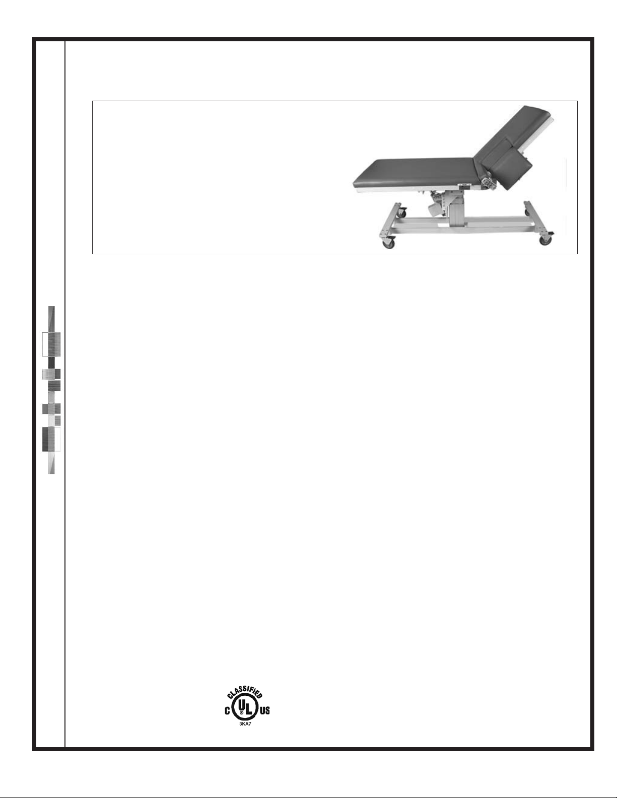
Model 1133 Shown
SPECIFICATIONS
LENGTH 80”
WIDTH 30”
WEIGHT 345 lbs
.
FOAM Cal. B.F.T.B. #117
VINYL Fed. Spec. Cec-A-680A
D.O.T. FAR 25.8536, M.V.S. 302
Port of NY/ Boston F.D. Code
ELECTRICAL 120 VAC; 2.6 amps max; UL 601 Classified,
CAN/CSA 22.2 No. 601.1, IEC
60601-1
WARRANTY
5 Years - All electrical, mechanical and
structural parts
1 Year - Parts and labor
(see Warranty for complete details)
HOSPITAL SPECIFIC
FEATURES
•
Electrically adjustable fowler positioning 0-65°
•
1,250 lb. Load capacity
•
500 lb. Lift capacity
• Single Pedal Braking
• Single Pedal Steering
• 3 Position memory hand controller
•
2 Collapsible/Removable safety rails
• Underwriters Laboratory listed for hospital use
(UL 601, CSA & IEC 60601-1 Standards)
•
#817 SafeTwedge™
•
#820 SafeTwedge™
•
IV pole holder
•
Corner bumpers
•
6 Standard vinyl colors
•
Paper roll holder & cutter
•
Leg support compatible
•
Head support compatible
EBSS0406
Medical Positioning, Inc. • 1717 Washington • Kansas City, Missouri 64108 • 800-593-3246 • FAX (816) 474-7755 • www.medicalpositioning.com
FEATURES
• Proven faster image acquisition
• Anatomically/Ergonomically correct imaging
area
•
14" x 14" Exam drop section
One hand rapid release
Patented non-pinch closure
• Synchronized, dual latch bolt locks with
stainless steel receiver plates
• Sonographer ergonomics and patient
transfer system
• Electrically controlled pedestal base
• Sealed, water resistant, low voltage, control
wand with self-retracting, coiled power cord
• Vascular positioning
• Blood pressure restoration system
• Certified patient safe - pinch point free design
• Electrically isolated, 24V/DC motion control
system with current overload protection circuit
• Storage tray
US Patents 6,353,949 B1; 5,950,262; 5,919,131; 347,691; 5,184,363; 5,461,739; 6,367,104 B1: additional patents pending
International Patents 195 81 706; 2,304,568
FDA Listed
FDA Registered Establishment
Page 43
MEDICAL POSITIONING
EBSS0406
Medical Positioning, Inc. • 1717 Washington • Kansas City, Missouri 64108 • 800-593-3246 • FAX (816) 474-7755 • www.medicalpositioning.com
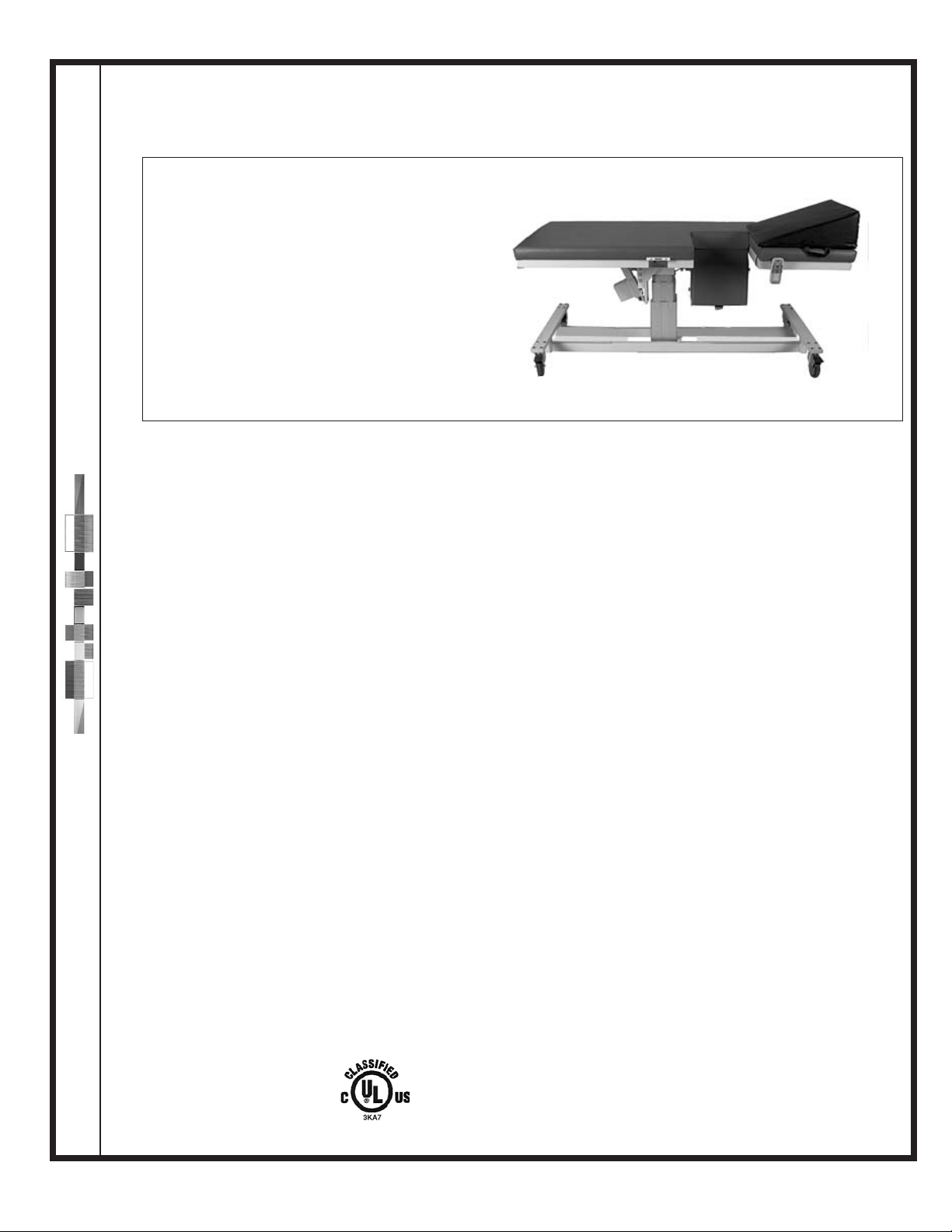
Model
1100 – Fully upgradeable to all options
Height - 28 1/2”
1101 – Height Adjustable 24" - 34"
1123 – Height Adjustable 24" - 34" &
Trendelenburg/ rev. Tren. (±15°)
Echo™Bed
Specifications for Models 1100, 1101, 1123
Model 1123 shown
WARRANTY
5 Years - All electrical, mechanical and
structural parts
1 Year - Parts and labor
(see Warranty for complete details)
Standard
collapsible/removable
safety rails
OPTIONS
• 2 Way Drop Section
• Leg supports
• Head supports
• Positioning SafeTwedges™
• 71 Optional vinyl colors
• Pediatric/Geriatric adapter
SPECIFICATIONS
LENGTH 73”
WIDTH 30”
WEIGHT 320 lbs
.
FOAM Cal. B.F.T.B. #117
VINYL Fed. Spec. Cec-A-680A
D.O.T. FAR 25.8536, M.V.S. 302
Port of NY/ Boston F.D. Code
ELECTRICAL 120 VAC; 1.6 amps max; UL 601 Classified,
CAN/CSA 22.2 No. 601.1, IEC 60601-1
HOSPITAL SPECIFIC
FEATURES
•
1,250 lb. Load capacity
•
500 lb. Lift capacity
•
Single pedal braking
• Single pedal steering
• 3 Position memory hand controller
•
2 Collapsible/Removable safety rails
• Underwriters Laboratory listed for hospital use
(UL 601, CSA & IEC 60601-1 Standards)
•
#817 SafeTwedge™
•
#820 SafeTwedge™
•
IV pole holder
•
Corner bumpers
•
6 Standard vinyl colors
•
Paper roll holder & cutter
•
Leg support compatible
•
Head support compatible
FEATURES
• Proven faster image acquisition
• Anatomically/Ergonomically correct imaging
area
•
14" x 14" Exam drop section
One hand rapid release
Patented non-pinch closure
• Synchronized, dual latch bolt locks with
stainless steel receiver plates
• Sonographer ergonomics and patient
transfer system
• Electrically controlled pedestal base
• Sealed, water resistant, low voltage, control
wand with self-retracting, coiled power cord
• Vascular positioning
• Blood pressure restoration system
• Certified patient safe - pinch point free design
• Electrically isolated, 24V/DC motion control
system with current overload protection circuit
• Storage tray
US Patents 6,353,949 B1; 5,950,262; 5,919,131; 347,691; 5,184,363; 5,461,739; 6,367,104 B1: additional patents pending
International Patents 195 81 706; 2,304,568
FDA Listed
FDA Registered Establishment
Page 44
MEDICAL POSITIONING
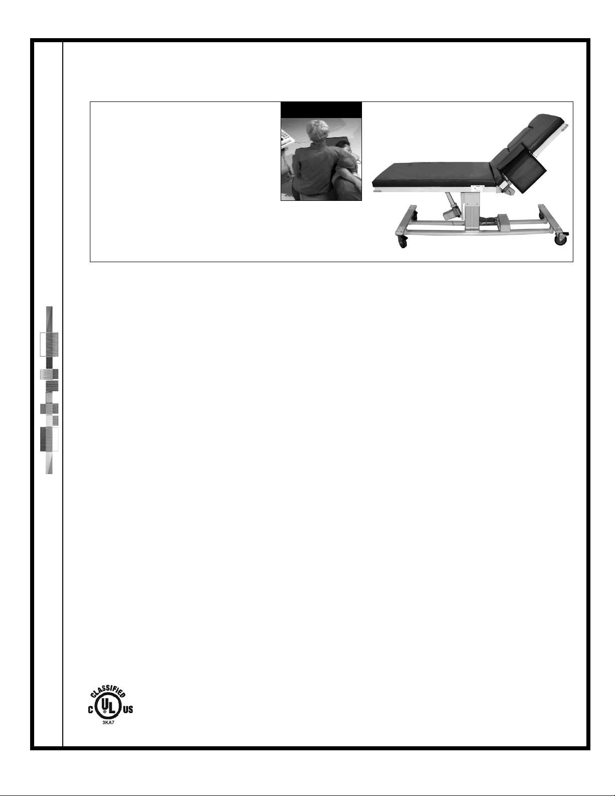
Model
1202 – Fully upgradeable to all options
Height - 28 1/2
1222 – Height Adjustable 24" - 34"
1233 – Height Adjustable 24" - 34" &
Trendelenburg/ rev. Tren. (±15°)
Echo™Bed Dual
Specifications for Models 1202, 1222, 1233
OPTIONS
• Leg supports
• Head supports
• Positioning SafeTwedges™
• 71 optional vinyl colors
• Pediatric/Geriatric adapter
Standard
collapsible/removable
safety rails
Optimal Posture
EBSS0406
Medical Positioning, Inc. • 1717 Washington • Kansas City, Missouri 64108 • 800-593-3246 • FAX (816) 474-7755 • www.medicalpositioning.com
SPECIFICATIONS
LENGTH 80”
WIDTH 30”
WEIGHT 340 lbs
.
FOAM Cal. B.F.T.B. #117
VINYL Fed. Spec. Cec-A-680A
D.O.T. FAR 25.8536, M.V.S. 302
Port of NY/ Boston F.D. Code
ELECTRICAL 120 VAC; 2.6 amps max; UL 601 Classified,
CAN/CSA22.2 No. 601.1, IEC 60601-1
HOSPITAL SPECIFIC
FEATURES
•
Electrically adjustable fowler positioning 0-65°
•
1,250 lb. Load capacity
•
500 lb. Lift capacity
• Single pedal braking
• Single pedal steering
• 3 Position memory hand controller
•
2 Collapsible/Removable safety rails
• Underwriters Laboratory listed for hospital use
(UL 601, CSA & IEC 60601-1 Standards)
•
#817 SafeTwedge™
•
IV pole holder
•
Corner bumpers
•
6 Standard vinyl colors
•
Paper roll holder & cutter
•
Leg support compatible
•
Head support compatible
FEATURES
• Proven faster image acquisition
• Anatomically/Ergonomically correct imaging
area
•
14" x 14" Exam drop section
One hand rapid release
Patented non-pinch closure
•
14" x 13" Right sided sonographers 2 way drop
section w/ Exam side remote release
Patented non-pinch closure
•
Sonographer drop section extension
• Synchronized, dual latch bolt locks with stainless steel receiver plates
• Sonographer ergonomics and patient
transfer system
• Electrically controlled pedestal base
• Sealed, water resistant, low voltage, control
wand with self-retracting, coiled power cord
• Vascular positioning
• Blood pressure restoration system
• Certified patient safe - pinch point free design
• Electrically isolated, 24V/DC motion control
system with current overload protection circuit
• Storage tray
WARRANTY
5 Years - All electrical, mechanical and structural parts
1 Year - Parts and labor
(see Warranty for complete details)
US Patents 6,353,949 B1; 5,950,262; 5,919,131; 347,691; 5,184,363; 5,461,739; 6,367,104 B1: additional patents pending
International Patents 195 81 706; 2,304,568
FDA Listed
FDA Registered Establishment
Page 45
MEDICAL POSITIONING
MPSS0406
Medical Positioning, Inc. 1717 Washington • Kansas City, Missouri 64108 • 800-593-3246 • FAX (816) 474-7755 • www.medicalpositioning.com
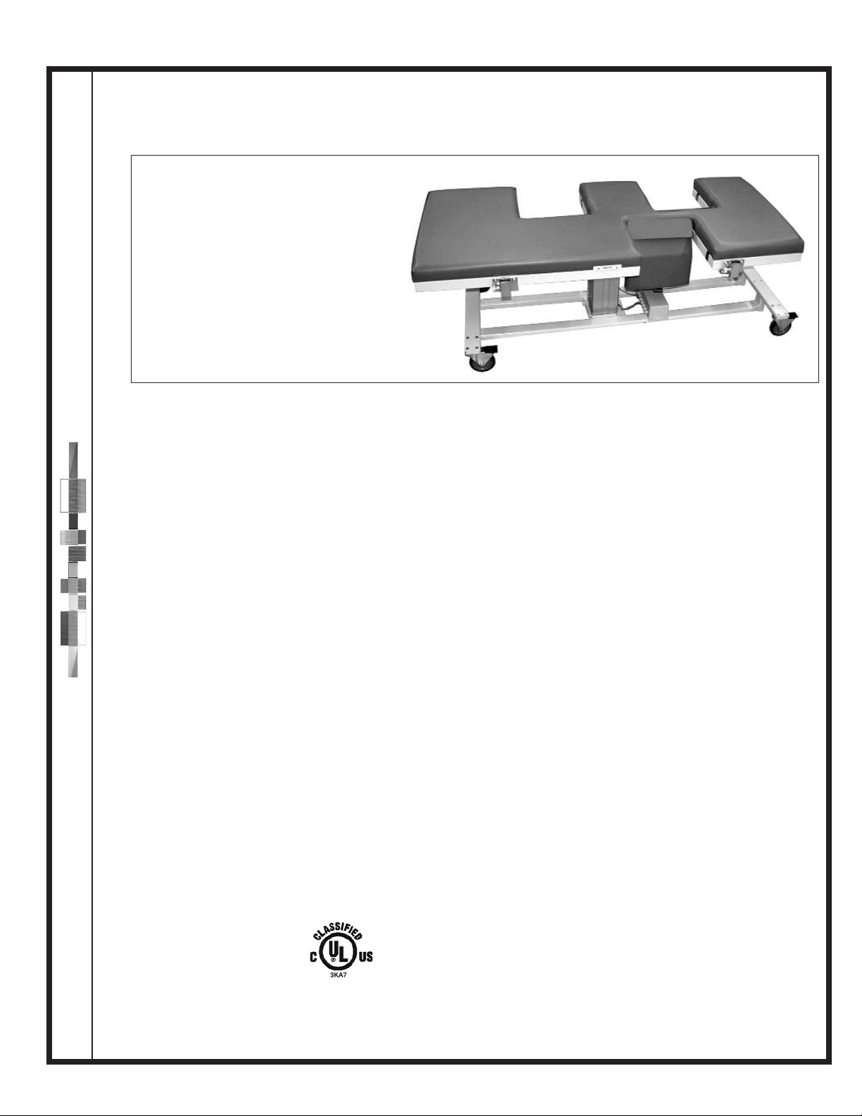
All Ways™Echo™Bed
Specifications for Models 1300, 1301, 1303, 1323
Features & Benefits
Model
1300 – Fully upgradeable to all options
Height - 26”
1301 – Height Adjustable 24" - 32"
1303 – Fixed Height - 26”
Trendelenburg/ rev. Trend. (±15°)
1323 – Height Adjustable 26” - 34” &
Trendelenburg/ rev. Trend. (±15°)
Specifications
LENGTH: 73"
WIDTH 30"
WEIGHT 300 lbs.
LOAD CAP. 1250 lbs.
LIFT CAP. 500 lbs.
FOAM Cal. B.F.T.B. #117
VINYL Fed. Spec. Cec-A-680A
D.O.T. FAR 25.8536, M.V.S. 302
Port of NY/ Boston F.D. Code
ELECTRICAL 110 VAC/24 VDC, UL 2601 Classified,
CAN/CSA 22.2 No. 601.1, IEC 60601-1
•
1,250 lb. Load capacity
•
500 lb. Lift capacity
• 3 Position memory hand controller
•
2 Collapsible/Removable safety rails
•
#817 SafeTwedge™
• Underwriters Laboratory listed
(UL 601, CSA & IEC 60601-1 Standards)
•
Corner bumpers
•
7 Standard vinyl colors
• Quickly change room configuration for left or right
handed imaging (additional drop section) & center
pivot
• Anatomically/Ergonomically correct imaging
area
• Two
14" x 14" exam drop section
One hand rapid release
Patented non-pinch closure
•
14" x 13" right sided sonographers 2-way drop
section w/ exam side remote release
•
Sonographer drop section extension
• Proven faster image acquisition for both right & left
side sonographers – fewer false negative studies
• Largest image area available – eliminates patient
repositioning & provides maximum imaging area
Options
• Paper Roll Holder & Cutter
• Storage Tray
• 4 different positioning SafeTwedges™
• 71 optional vinyl colors
WARRANTY
5 Years - All electrical, mechanical and
structural parts
1 Year - Parts and labor (see Warranty for
complete details)
All Ways™Echo™Bed
US Patents 6,353,949 B1; 5,950,262; 5,919,131; 347,691; 5,184,363; 5,461,739; 6,367,104 B1: additional patents pending
International Patents 195 81 706; 2,304,568
FDA Listed
FDA Registered Establishment
 Loading...