

Page 1
\EDIC@
Manual
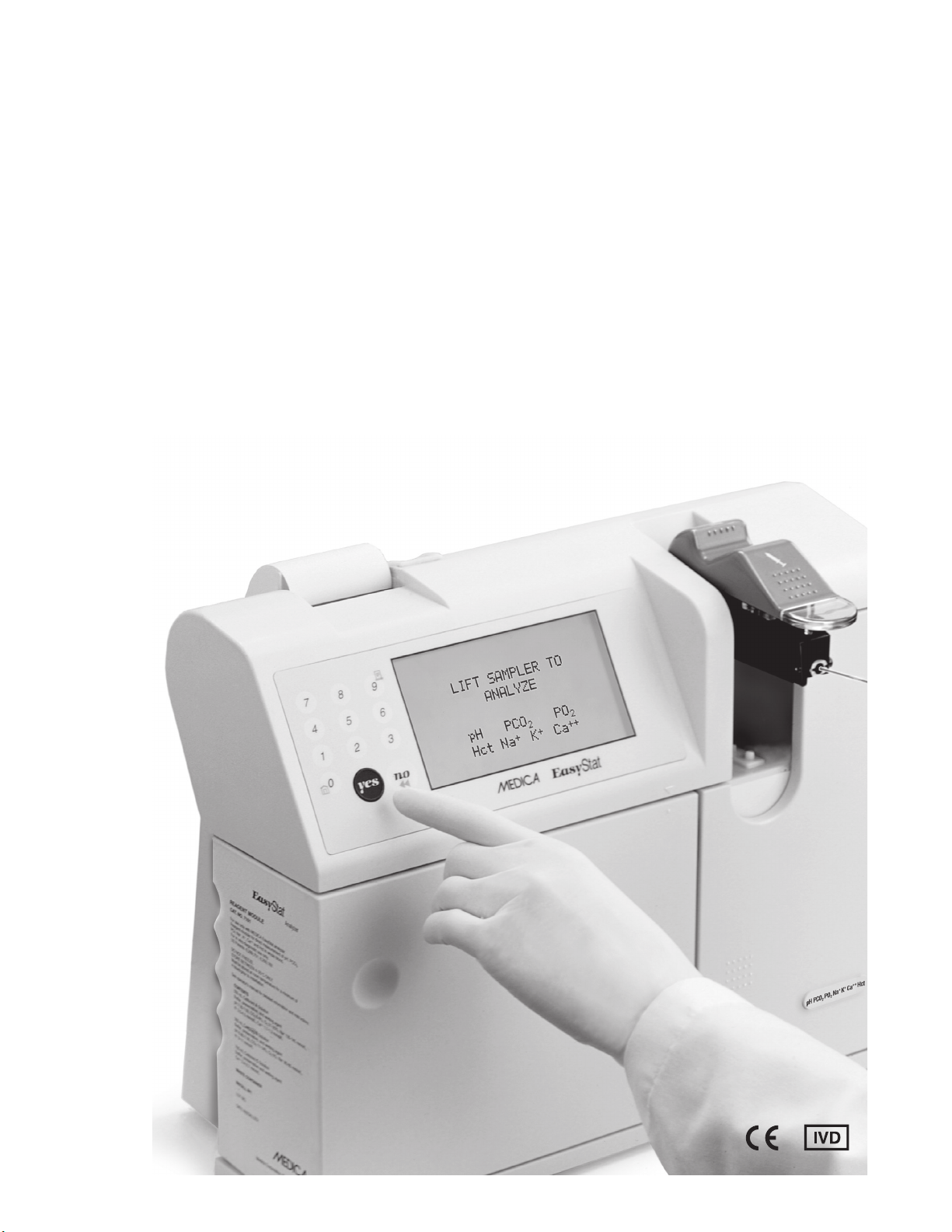
EasyStat
Operator’s
Page 2
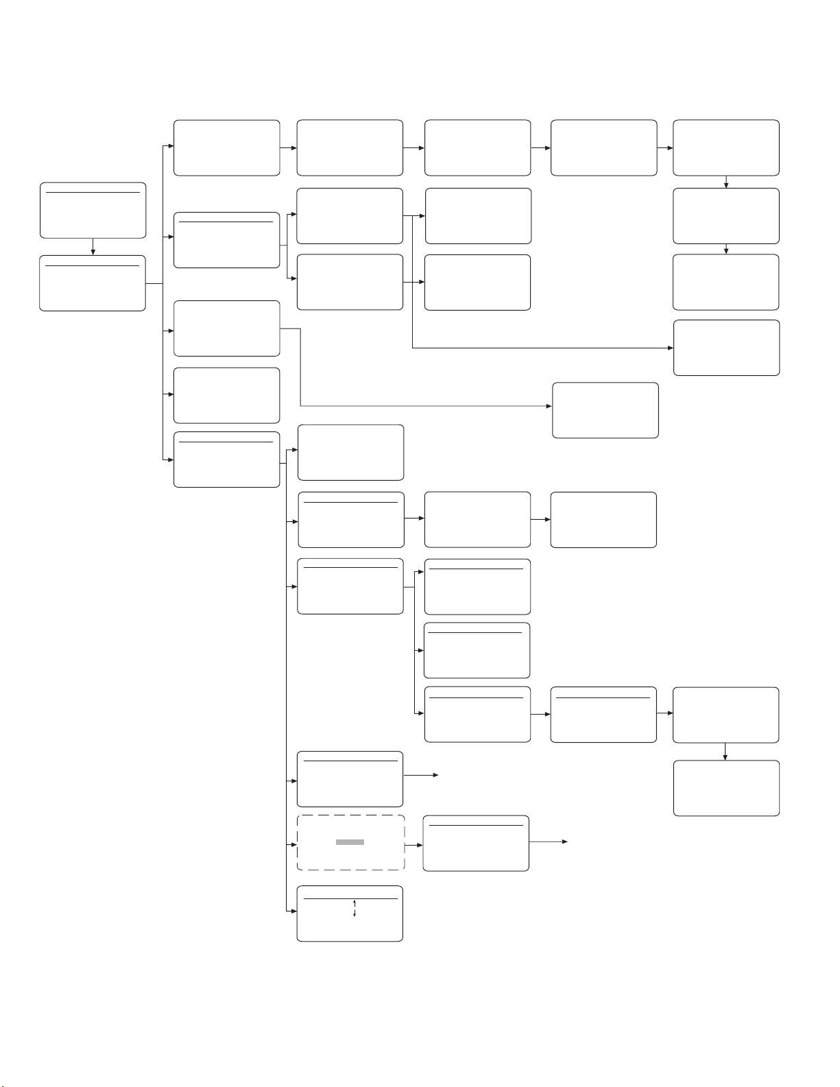
Flow Charts
HOME MENU
1 *
2 *
3 CALIBRAT E
4 DAILY CLEANER
5 SECOND MENU
HOME MENU
1 ANALYZE SAMPLE
2 ANALYZE QC
3 CALIBRAT E
4 DAILY CLEANER
5 SECOND MENU
LIFT SAMPLER TO
ANALYZE
pH PCO2 PO2
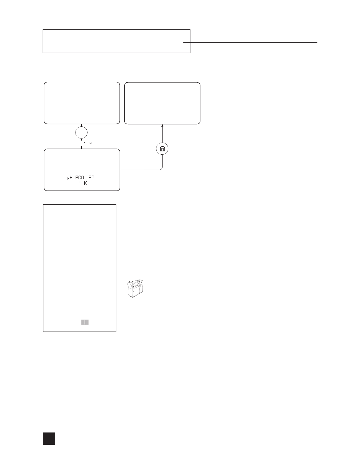
+
K+ Ca
++
Hct Na
ANALYZE QC
1 LEVEL 1
2 LEVEL 2
3 LEVEL 3
4 Hct LEVEL 1
5 Hct LEVEL 2
6 PROFICIENCY
CALIBRATE
CALIBRATING . . .
DAILY CLEANER
LIFT SAMPLER TO
USE CLEANER
SECOND MENU
1 STANDBY
2 REPLACE COMPONENTS
3 DIAGNOSTICS
4 STORED INFORMATION
5 SETUP MENU
6 ADJUST DISPLAY
ENTER PATIENT DATA 1/2
ID
PAT. TEMP 37.0
THb 14.5 g/dL
FIO
2
TIME DRAWN 00.00
21%
CONFIRM ?
QC LEVEL 1
LOT # XXXXXX
LIFT SAMPLER TO
ANALYZE CONTROL
QC HcT LEVEL 1
LOT # XXXXXX
LIFT SAMPLER TO
ANALYZE CONTROL
MANUAL STANDBY
CONFIRM ?
REPLACE COMPONENTS
1 REAGENT MODULE
2 ELECTRODES
3 PUMP TUBING
4 SENSOR MODULE/SAMPLER
5 VA LVE MODULE
6 SWITCH TO Ca
DIAGNOSTICS
1 TEST COMPONENTS
2 TEST FLUIDICS
3 SENSOR STATUS
4 PRIME FLUIDS
5 PRINT mV
++
/ Cl-
’s
ENTER PATIENT DATA 2/2
SAMPLE TYPE ARTERIAL
SAMPLE SITE RADIAL
OPERATOR ID?
CONFIRM ?
QC LEVEL 1
pH 7.203
PCO
32.5 mmHg
2
PO
118 mmol/L
2
+
Na
140.9 mmol/L
+
K
4.50 mmol/L
++
Ca
2.33 mmol/L
STORE RESULTS ?
QC HcT LEVEL 1
Hct 55 %
STORE RESULTS ?
If incorrect barcode scanned
If all channels failed
Cl- MODE ?
TEST COMPONENTS
1 PUMP
2 VA LVE
3 SAMPLER SWITCHES
4 DOOR SWITC H
5 REAGENT READER
ANALYSIS RESULTS #001
pH 7.203
PCO
32.5 mmHg
2
PO
118 mmol/L
2
Hct 45%
+
Na
140.1 mmol/L
+
K
4.02 mmol/L
++
Ca
2.33 mmol/L
SLOPES
pH 23.99
34.00
PCO
2
PO2 99.99
Hct 87.34
+
++
CONFIRM ?
10.78
41.00
10.00
Na
+
K
Ca
PATIENT RESULTS
WILL BE LOST
CALCULATED VALUES 1/3
THb XXX g/dL
pH (T) XXX
PCO
(T) XXX mmHg
2
(T) XXX mmHg
PO
2
TCO
XXX mmol/L
2
HCO
XXX mmol/L
3
XXX mmol/L
BEb
CALCULATED VALUES 2/3
BEecf XXX mmol/L
SBC XXX mmol/L
%sO
c XXX
2
ctO
XXX mL/L
2
CALCULATED VALUES 3/3
A-aDO2 XXX mmHG
RI XXX
++
Ca
(7.4) XXX mmol/L
QC LEVEL 1
LOT # XXXXXX
LIFT SAMPLER TO
ANALYZE CONTROL
STORED INFORMATION
1 PATIENT RESULT S
2 QC RESULT S
3 REFERENCE LIMITS
4 CAL / SAMPLE # DATA
5 REAGENT MODULE
6 PRINTOUTS
SECURITY CODE
* * * *
CONFIRM ?
ADJUST DISPLAY
1 BRIGHTNESS
2 BRIGHTNESS
3 REVERSE
Note: Ca++ will be replaced by Cl- in Cl- mode.
Ca++ (7.4) will be replaced by Anion Gap in Cl- mode
TEST FLUIDICS
1 REAGENT FLOW
2 SAMPLE FLOW
3 BUBBLE DETECTOR CAL
4 PUMP CAL
SENSOR STATUS
1 ELECTRODE mV’s
2 BAROMETRIC PRESSURE
3 TEMPERATURES
FLOWCHA RT 3
SETUP MENU
1 USER OPTIONS
2 CONFIGURATION
3 PRINTER OPTIONS
4 SET REFERENCE LIMITS
5 PATIENT INFORMATION
6 DELETE DATA
ELECTRODE mV’s
1 CALIBRANT A mV
2 CALIBRANT B mV
3 CALIBRANT C mV
FLOWCHA RT 2
’s
’s
’s
ELECTRODE mV’s
CALIBRANT A mV’s
pH XX.X
PCO
XX.X
2
PO
XX.X
2
ELECTRODE mV’s
CALIBRANT A mV’s
Hct XXX.X
+
Na
XX.X
+
K
XX.X
++
Ca
XX.X
Page 3
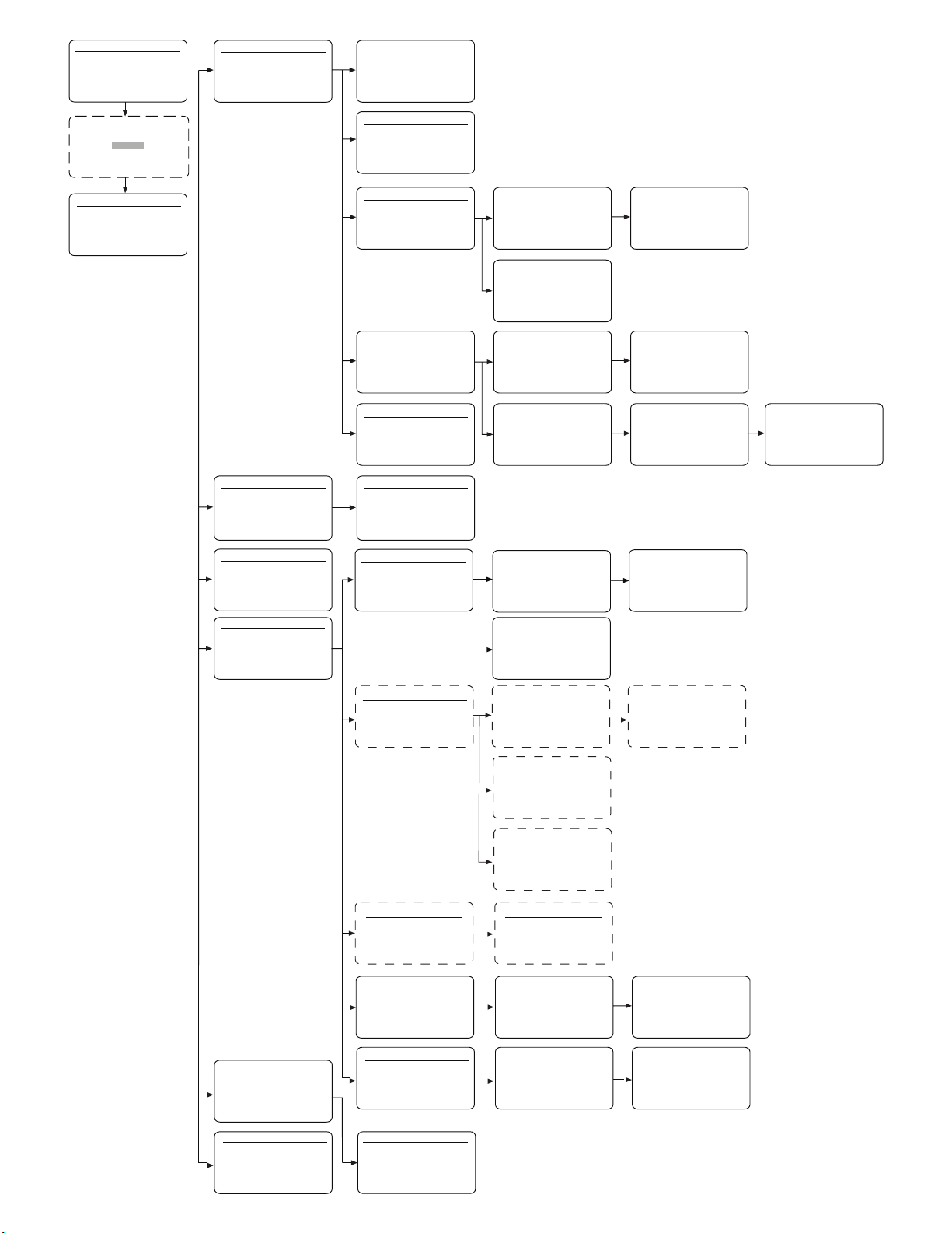
SECOND MENU
1 STANDBY
2 REPLACE COMPONENTS
3 DIAGNOSTICS
4 STORED INFORMATION
5 SETUP MENU
6 ADJUST DISPLAY
SECURITY CODE
* * * *
CONFIRM ?
USER OPTIONS
1 DATE / TIME
2 LANGUAGE
3 CORRELATION
4 REPORTED PATIENT DATA
5 BAROMETRIC PRESSURE
6 SECURITY CODE
DATE / TIME
DEC - 05 - 2001; 15:30
CONFIRM ?
LANGUAGE
1 ENGLISH
SETUP MENU
1 USER OPTIONS
2 CONFIGURATION
3 PRINTER OPTIONS
4 SET REFERENCE LIMITS
5 PATIENT INFORMATION
6 DELETE DATA
CONFIGURATION 1/2
1 PO2 / PCO2 / BP mmHg
+ / K+
++
/ Ca
mmol/L
CONFIRM ?
g/dL
2 Na
3 Hct %
4 Hb
5 BC CHECKSUM OFF
PRINTER OPTIONS
1 PRINTER ON
2 CALC’D VALUES ON
3 PRINTO UTS 1
SET REFERENCE LIMITS
1 QC
2 NORMAL
3 CRITICAL
4 AMR
CORRELATION
1 SET PARAMETERS
2 APPLY CORRELATION
REPORTED PATIENT DATA
1 ANALYTES
2 CALCULATED VALUES
BAROMETRIC PRESSURE
CURRENT READING
XXX.X mmHg
CONFIRM ?
CONFIGURATION 2/2
1 CAL FREQUENCY 8 HRS
2 AUTO STANDBY OFF
3 TEMPERATURE C
4 Rili-BAK OFF
5 AMR OFF
CONFIRM ?
SET QC REFERENCE LIMITS
1 LEVEL 1
2 LEVEL 2
3 LEVEL 3
4 Hct LEVELS
SET Rili-BAK LIMITS
1 LEVEL 1
2 LEVEL 2
3 LEVEL 3
4 Hct LEVEL 1
5 Hct LEVEL 2
CORRELATION 1/2
SET PARAMETERS
SLOPE INTERCEPT
pH = X.XXXX + X.XXX
= X.XXX + X.X mmHg
PCO
2
PO
= X.XXX + X mmHg
2
Hct = X.XXX + X %
CONFIRM ?
APPLY CORRELATION
1 PATIENT RESULTS OFF
2 QC RESULTS OFF
CONFIRM ?
REPORTED PATIENT DATA 1/2
ANALYTES
1 pH ON
ON
2 PCO
2
ON
3 PO
2
4 Hct ON
CONFIRM ?
REPORTED PATIENT DATA 1/3
CALCULATED VALUES
1 THb ON
2 pH (T) ON
3 PCO
(T) ON
2
4 PO
(T) ON
2
5 TCO
CONFIRM ?
2
SET REFERENCE LIMITS 1/2
QC LEVEL 1
LOT #XXXXXXX
pH X.XXX-X.XXX
XXX.X-XXX.X mmHg
PCO
2
XXX- XXX mmHg
PO
2
CONFIRM ?
SET REFERENCE LIMITS
QC Hct LEVEL 1
LOT #XXXXXXX
Hct XX
-
XX %
QC Hct LEVEL 2
LOT #XXXXXXX
Hct XX
-
CONFIRM ?
SET REFERENCE LIMITS 1/6
Rili-BAK LEVEL 1
LOT #XXXXXXX
pH
TARGET X.XXX mmHg
DEVIATION X.X %
RILIBAK X.XXX
TARGET XX %
DEVIATION XX %
RILIBAK
SET REFERENCE LIMITS
TARGET XX %
DEVIATION XX %
RILIBAK
-
CONFIRM ?
SET REFERENCE LIMITS
Rili-BAK LEVEL 1
LOT #XXXXXXX
Hct
XX-XX %
CONFIRM ?
Rili-BAK LEVEL 2
LOT #XXXXXXX
Hct
XX
CONFIRM ?
ON
XX %
X.XXX mmHg
-
XX %
CORRELATION 2/2
SET PARAMETERS
SLOPE INTERCEPT
Na+ = X.XXX + X.X mmol/L
+
K
= X.XXX + X.XX mmol/L
++
Ca
= X.XXX + X.XX mmol/L
CONFIRM ?
REPORTED PATIENT DATA 2/2
ANALYTES
1 Na+ ON
+
2 K
ON
++
3 Ca
ON
CONFIRM ?
REPORTED PATIENT DATA 2/3
CALCULATED VALUES
1 HCO3 ON
2 BEb ON
3 BEecf ON
4 SBC ON
c
5 %s0
CONFIRM ?
2
SET REFERENCE LIMITS 2/2
QC LEVEL 1
LOT #XXXXXXX
+
-
Na
XXX.X
+
K
Ca
SET REFERENCE LIMITS 2/6
TARGET X.XXX mmHg
DEVIATION X.X %
RILIBAK X.XXX
XXX.X mmol/L
X.XX X.XX mmol/L
-
++
X.XX X.XX mmol/L
-
CONFIRM ?
Rili-BAK LEVEL 1
LOT #XXXXXXX
pCO
2
-
X.XXX mmHg
CONFIRM ?
REPORTED PATIENT DATA 3/3
1 ctO2 ON
2 A-aDO
3 RI ON
ON
4 Ca
CONFIRM ?
CALCULATED VALUES
ON
2
++
(7.4)
ON
PATIENT INFORMATION 1/2
1 PATIENT ID OFF
2 PATIENT TEMP OFF
3 Hb OFF
4 FI O
2
5 TIME DRAW N OFF
CONFIRM ?
DELETE DATA
1 ALL QC LEVEL 1
2 ALL QC LEVEL 2
3 ALL QC LEVEL 3
4 ALL QC Hct LEVEL 1
5 ALL QC Hct LEVEL 2
6 ALL PATIENT RESULT S
SET AMR LIMITS 1/2
pH X.XXX-X.XXX
PCO
PO
2
Hct XX
SET NORMAL LIMITS
1 ARTERIAL
2 MIXED VENOUS
3 VENOUS
SET CRITICAL LIMITS
1 ARTERIAL
2 MIXED VENOUS
3 VENOUS
OFF
PATIENT INFORMATION 2/2
1 SAMPLE TYPE OFF
2 SAMPLE SITE OFF
3 OPERAT OR ID OFF
CONFIRM ?
XXX.X-XXX.X mmHg
2
XXX-XXX mmHg
-
XX %
CONFIRM ?
SET AMR LIMITS 2/2
Na+ XXX.X-XXX.X mmol/L
+
K
X.XX-X.XX mmol/L
++
X.XX-X.XX mmol/L
Ca
CONFIRM ?
SET REFERENCE LIMITS 1/2
NORMAL
ARTERIAL
pH X.XXX-X.XXX
PCO
XXX.X-XXX.X mmHg
2
XXX-XXX mmHg
PO
2
-
Hct XX
CONFIRM ?
SET REFERENCE LIMITS 1/2
pH X.XXX-X.XXX
PCO
PO
Hct XX
CONFIRM ?
XX %
CRITICAL
ARTERIAL
XXX.X-XXX.X mmHg
2
XXX-XXX mmHg
2
-
XX %
SET REFERENCE LIMITS 2/2
NORMAL
ARTERIAL
+
Na
-
XXX.X mmol/L
XXX.X
+
K
X.XX-X.XX mmol/L
++
X.XX-X.XX mmol/L
Ca
CONFIRM ?
SET REFERENCE LIMITS 2/2
CRITICAL
ARTERIAL
Na+ XXX.X-XXX.X mmol/L
+
X.XX-X.XX mmol/L
K
++
X.XX-X.XX mmol/L
Ca
CONFIRM ?
Page 4
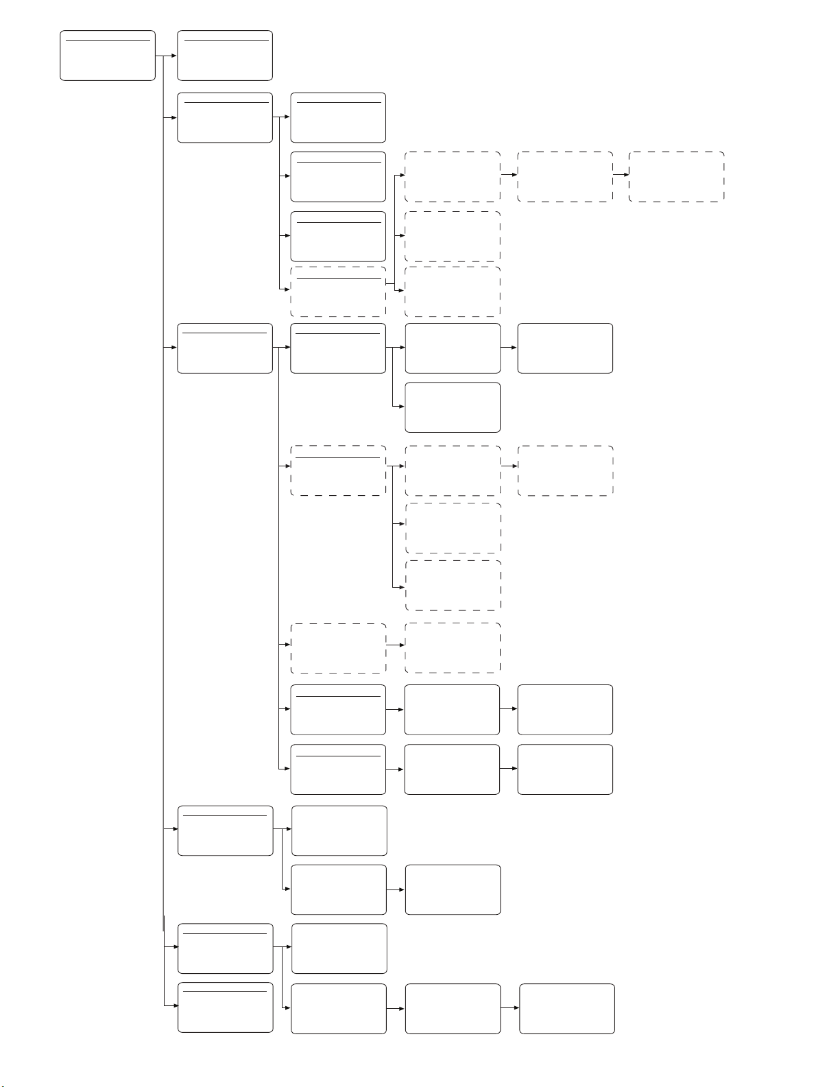
STORED INFORMATION
1 PATIENT RESULTS
2 QC RESULTS
3 REFERENCE LIMITS
4 CAL/SAMPLE # DATA
5 REAGENT MODULE
6 PRINTOUTS
PATIENT RESULTS
1 LAST
2 ALL
3 ENTER ID#
QC RESULTS
1 LAST CONTROL
2 PRINT QC STATS
3 PRINT QC RESULTS
4 PLOT QC CHARTS
5 FAILED QC
LAST CONTROL
1 LEVEL 1
2 LEVEL 2
3 LEVEL 3
4 Hct LEVEL 1
5 Hct LEVEL 2
REFERENCE LIMITS
1 QC
2 NORMAL
3 CRITICAL
4 AMR
PRINT QC STATS
1 LEVEL 1
2 LEVEL 2
3 LEVEL 3
4 Hct LEVEL 1
5 Hct LEVEL 2
6 ALL LEVELS
PLOT QC CHARTS
1 pH
2 PCO
3 PO
4 Hct
FAILED QC
1 LEVEL 1
2 LEVEL 2
3 LEVEL 3
4 Hct LEVEL 1
5 Hct LEVEL 2
QC REFERENCE LIMITS
1 LEVEL 1
2 LEVEL 2
3 LEVEL 3
4 Hct LEVELS
Rili-BAK LIMITS
1 LEVEL 1
2 LEVEL 2
3 LEVEL 3
4 Hct LEVEL 1
5 Hct LEVEL 2
2
2
+
5 Na
+
6 K
++
7 Ca
8 ALL CHARTS
DEC-16 13:57
pH X.XXX
PCO
PO
Na
+
K
Ca
REMOVE FROM STATS ?
DEC-16 13:57
XXX.X
2
XXX
2
+
XXX.X
X.XX
++
X.XX
Hct LEVEL 1
X.XX %
1/XX
1/XX
REMOVE FROM STATS ?
DEC-16 13:57
Hct LEVEL 2
1/XX
X.XX %
REMOVE FROM STATS ?
REFERENCE LIMITS 1/2
QC LEVEL 1
LOT # XXXXXXX
pH X.XXX
PCO
PO
2
REFERENCE LIMITS 1/6
TARGET X.XXX mmHg
DEVIATION X.XX %
RILIBAK X.XXX
TARGET XX %
DEVIATION X.X %
RILIBAK
TARGET XX %
DEVIATION X.X %
RILIBAK
X.XXX
XXX.X-XXX.X mmHg
2
XXX-XXX mmHg
REFERENCE LIMITS
QC Hct LEVEL 1
LOT #XXXXXXX
Hct XX
-
XX %
QC Hct LEVEL 2
LOT #XXXXXXX
Hct XX
-
XX %
CONFIRM ?
Rili-BAK LEVEL 1
LOT #XXXXXXX
pH
X.XXX mmHg
-
REFERENCE LIMITS
Rili-BAK LEVEL 1
LOT #XXXXXXX
Hct
XX-
XX %
REFERENCE LIMITS
Rili-BAK LEVEL 2
LOT #XXXXXXX
Hct
XX-
XX %
DEC-16 13:57
*
pH X.XXX
PCO
PO
XXX
2
+
Na
+
K
++
Ca
REFERENCE LIMITS 2/2
QC LEVEL 1
LOT # XXXXXXX
Na+ XXX.X-XXX.X mmol/L
+
X.XX-X.XX mmol/L
K
++
Ca
X.XX-X.XX mmol/L
REFERENCE LIMITS 2/6
Rili-BAK LEVEL 1
LOT #XXXXXXX
TARGET X.XXX mmHg
DEVIATION X.XX %
RILIBAK X.XXX
XXX.X
2
XXX.X
X.XX
X.XX
CONFIRM ?
pCO2
-
1/XX
X.XXX mmHg
DEC-12 16:25
pH X.XXX
PCO
PO
2
+
Na
+
K
++
Ca
REMOVE FROM STATS ?
XXX.X
2
XXX
XXX.X
X.XX
X.XX
2/XX
CAL / SAMPLE # DATA
1 SLOPES
2 mV’s
3 PUMP / BUBBLE DETECTOR
4 SAMPLE COUNTER
REAGENT MODULE
1 STATUS
2 CONCENTRATIONS
PRINTOUTS
1 USER OPTIONS
2 CONFIGURATION
3 PRINTER OPTIONS
4 PATIENT LIMITS
5 QC LIMITS
6 PATIENT INFORMATION
REFERENCE LIMITS 1/2
AMR
pH X.XXX-X.XXX
PCO
XXX.X-XXX.X mmHg
2
PO
XXX-XXX mmHg
2
NORMAL LIMITS
1 ARTERIAL
2 MIXED VENOUS
3 VENOUS
CRITICAL LIMITS
1 ARTERIAL
2 MIXED VENOUS
3 VENOUS
SLOPES
pH 23.99 PASS
PCO
34.00 PASS
2
PO
99.99 PASS
2
Hct 87.34 PASS
+
Na
10.78 PASS
+
K
41.00 PASS
++
Ca
30.00 PASS
CAL / SAMPLE # DATA 1/2
mv’S
CAL A CAL B CAL C
pH XX.X XX.X XX.X
PCO
XX.X XX.X XX.X
2
PO2 XX.X XX.X XX.X
Hct XX.X XX.X XX.X
REAGENT MODULE
STATUS
S/N 0001-0200-03-001
INSTALLED DEC-05-01
UNIT S/N 0123456789
98 %, 30 DAYS
REAGENT MODULE 1/3
CONCENTRATIONS
Cal pH PCO2 PO2
mmHg mmHg
A X.XXX XXX.X XXX
B X.XXX XXX.X XXX
C X.XXX XXX.X XXX
REFERENCE LIMITS 2/2
AMR
Na+ XXX.X-XXX.X mmol/L
+
X.XX-X.XX mmol/L
K
++
Ca
X.XX-X.XX mmol/L
Hct XX
REFERENCE LIMITS 1/2
pH X.XXX-X.XXX
PCO
PO
Hct XX
REFERENCE LIMITS 1/2
pH X.XXX-X.XXX
PCO
PO
Hct XX
CAL / SAMPLE # DATA 2/2
Na
K
Ca
Cal Hct Na+ K+
% nmol/L nmol/L
A XX XXX.X XX.X
B XX XXX.X XX.X
C XX XXX.X XX.X
XX %
-
NORMAL
ARTERIAL
XXX.X-XXX.X mmHg
2
XXX-XXX mmHg
2
-
XX %
CRITICAL
ARTERIAL
XXX.X-XXX.X mmHg
2
XXX-XXX mmHg
2
-
XX %
mv’S
CAL A CAL B CAL C
+
XX.X XX.X XX.X
+
XX.X XX.X XX.X
++
XX.X XX.X XX.X
REAGENT MODULE 2/3
CONCENTRATIONS
REFERENCE LIMITS 2/2
NORMAL
ARTERIAL
Na+ XXX.X-XXX.X mmol/L
+
X.XX-X.XX mmol/L
K
++
Ca
X.XX-X.XX mmol/L
REFERENCE LIMITS 2/2
CRITICAL
ARTERIAL
Na+ XXX.X-XXX.X mmol/L
+
X.XX-X.XX mmol/L
K
++
Ca
X.XX-X.XXX mmol/L
REAGENT MODULE 3/3
CONCENTRATIONS
Cal Ca++
nmol/L
A X.XXX
B X.XXX
C X.XXX
Page 5

\EDIC@
EasyStat
Operator’s Manual
Ref. 7415
003770-901R1, 2015-07
Page 6

©2015 Medica Corporation (all rights reserved)
No part of this manual may be reproduced in any form without prior consent in writing from Medica Corporation.
The Medica EasyStat® analyzer is for In Vitro Diagnostic Use.
Medica Corporation, 5 Oak Park Drive
Bedford, MA 01730-1413 USA
Emergo Europe, Molenstraat 15
NL-2513 BH The Hague, The Netherlands
EasyStat® and EasyQC® are registered trademarks of Medica Corporation.
The information in this manual was correct at the time of printing. However, Medica Corporation continues to improve products and reserves
the right to change specifications, equipment, and maintenance procedures at any time without notice.
If the system is used in a manner differently than specified by Medica Corporation, performance of the equipment may be impaired. See all
Hazards, Precautions and Warnings.
Page 7

Preface
This Operator’s Manual will assist you in using the EasyStat analyzer. Easy-to-follow instructions guide
you through analyzer setup and operation. Display messages and flow charts are combined with the
written instructions for quick reference.
Symbols used throughout the manual
EasyStat display messages
important information
biohazard warning
sampler positioning required by operator
syringe sample mode
capillary sample mode
compression plate positioning required by operator
DISPLAY TYPE
s
H
conditions which may cause data loss or analyzer malfunction
access door must be closed for proper operation
1
Page 8

Contents
Preface
1 Understanding the EasyStat Analyzer
Intended Use ..................................................................................................................................... 5
Operational Hazards and Precautions ................................................................................................ 6
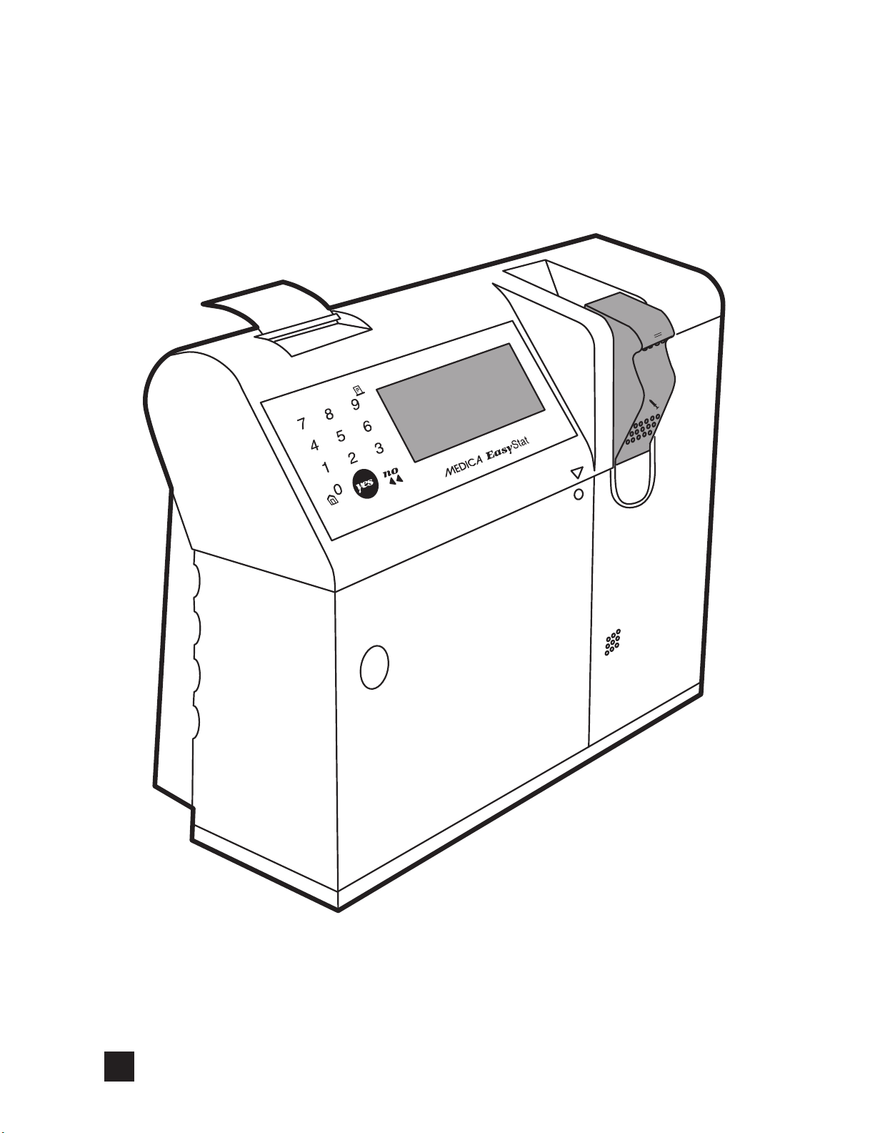
2 Analyzer Layout
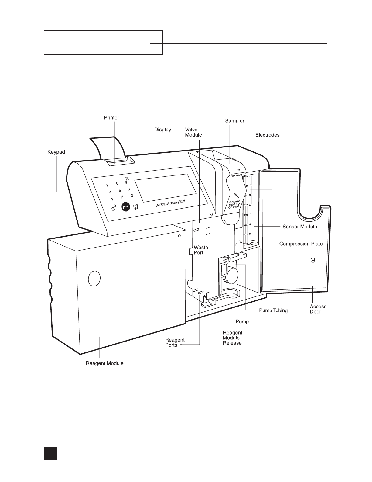
Front View ........................................................................................................................................8
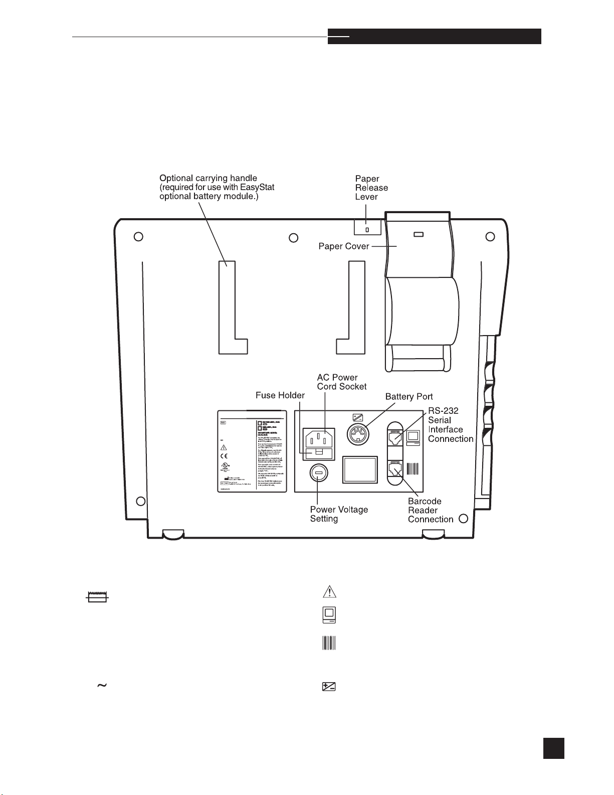
Rear View ......................................................................................................................................... 9
Keypad ...........................................................................................................................................10
Display ...........................................................................................................................................11
Fluid Path Description ......................................................................................................................12
3 Analyzer Installation
Unpacking ......................................................................................................................................14
Location ..........................................................................................................................................15
Power Up ........................................................................................................................................16
Date/Time.......................................................................................................................................17
Components ....................................................................................................................................18
4 Operating the Analyzer
Calibrate.........................................................................................................................................22
Analyze Sample ..............................................................................................................................24
Analyze QC ....................................................................................................................................32
Daily Cleaner ..................................................................................................................................40
Second Menu ..................................................................................................................................42
Standby ..........................................................................................................................................43
Replace Components .......................................................................................................................44
Analyzer Surface Cleaning/Storage .................................................................................................64
Diagnostics .....................................................................................................................................65
Stored Information ...........................................................................................................................74
Setup Menu.....................................................................................................................................82
Adjust Display .................................................................................................................................93
5 Sample Handling and Collection
Syringe Sample ...............................................................................................................................94
Capillary Sample ............................................................................................................................95
Interfering Substances ......................................................................................................................95
2
Page 9

6 Principles of Operation/Theory
pH, Na+, K+, Ca++, and Cl- Electrodes ...........................................................................................96
PCO2 Electrode .......................................................................................................................... 100
PO2 Electrode .............................................................................................................................. 100
Hct Sensor .................................................................................................................................. 101
Electrode Measurement/Diagrams ................................................................................................. 102
Tonometered Reagents .................................................................................................................. 103
Calculations ................................................................................................................................ 104
7 Specifications
............................................................................................................................................ 110
8 EasyStat Setup Defaults
............................................................................................................................................ 114
9 Troubleshooting
Introduction .................................................................................................................................. 115
Electrodes .................................................................................................................................... 117
Flow ............................................................................................................................................125
Reagent Module ........................................................................................................................... 134
Sensor Module ............................................................................................................................. 136
Valve Module ............................................................................................................................... 139
Printer .......................................................................................................................................... 141
Hardware .................................................................................................................................... 142
Quality Control ............................................................................................................................ 142
10 Computer Connection
............................................................................................................................................ 143
11 Replacement Schedule
............................................................................................................................................ 145
Appendices
Appendix A: Warranty ................................................................................................................ 147
Appendix B: Understanding the Symbols ...................................................................................... 14 9
3
Page 10
4
Page 11

1. Understanding the EasyStat Analyzer
Intended Use
The EasyStat analyzer is designed for clinical laboratory use, making direct measurements of pH (hydrogen ion activity), PCO2 (partial
pressure of carbon dioxide), PO2 (partial pressure of oxygen), Hct
(Hematocrit), Na+ (sodium), K+ (potassium), and Ca++ (ionized
Calcium) or Cl- (chloride) on whole blood samples from syringes or
capillary tubes.
Ca++ (ionized calcium) and Cl- (chloride) electrodes are interchangeable on the analyzer. The EasyStat can only measure Ca++ (ionized
calcium) or Cl- (chloride) at one time. After switching to the EasyStat
(Chloride) mode, the new Cl- electrode will occupy the same position
as the Ca++ electrode.
This analyzer is used by laboratory trained technicians in clinical
laboratories to aid in the diagnosis and treatment of patients with
electrolyte, blood gas and/or acid-base disturbances. The patient
results obtained from the EasyStat analyzer must be used in conjunction with the overall patient clinical condition before corrective/therapeutic action is taken.
The EasyStat analyzer also calculates the following parameters, based
on the equations outlined under Calculations in Principles of
Operation/Theory.
Total Hemoglobin: THb
•
• Temperature corrected pH: pH(T)
Temperature corrected PCO
•
Temperature corrected PO
•
Total Carbon Dioxide: TCO
•
Bicarbonate: HCO
•
Base Excess of blood: BE
•
Base Excess in extracellular fluid: BE
•
Standard Bicarbonate: SBC
•
Oxygen Saturation calculated at normal P
•
-
3
: PCO2(T)
2
: PO2(T)
2
2
b
ecf
: %SO2c
50
5
Page 12

u n d e r s t a n d i n g t h e a n a l y z e r
•
Total Oxygen Content: ctO
•
Alveolar-Arterial O
Respiratory Index: RI
•
Gradient: A-aDO
2
2
2
• Normalized calcium at pH = 7.4: Ca++ (7.4) when Ca++
channel is selected
• Anion Gap, when Cl- channel is selected
Operational Hazards and Precautions
Read the Operator’s Manual before setting up or operating the
EasyStat analyzer.
Observe all Warnings, Notes, and Key Information in this manual.
Failure to leave the analyzer connected to power with a reagent module in place could damage the electrodes, sensor module, valve module, and pump tubing.
There are no operator serviceable parts inside the analyzer. When
electromechanical problems beyond the scope of this Operator’s
Manual are suspected, DO NOT open the back cover. Contact your
EasyStat dealer.
Use only the supplied 3-wire (UL approved) power cord, or equivalent. The power cord of the analyzer must be connected to a matching
grounded outlet supplying 110~VAC, 50/60 Hz or 220~VAC, 50/60
Hz. The analyzer contains sensitive electronics and must be properly
grounded.
DO NOT plug the analyzer into a circuit protected by a Ground Fault
Interrupter (GFI).
The safety protection provided by the analyzer may be impaired when
the analyzer is used in any way other than as is outlined in this manual.
6
Page 13
u n d e r s t a n d i n g t h e a n a l y z e r
BIOHAZARD
All biological samples should be
considered biohazardous.
Any replaceable component which
comes in contact with biological samples, including the sample
probe, electrodes, sensor module,
pump tubing, valve module and
reagent module may contain contaminated material. Treat all components, during use and disposal,
as you would any biohazardous
material.
r
To clean the outside surfaces of the EasyStat analyzer, use a cleaning agent consisting of a 10% bleach (0.4-0.6% NaClO) solution.
Dampen a cloth with solution to wipe down all outside surfaces.
Protective clothing and gloves are recommended. Refer to the
Analyzer Surface Cleaning/Storage instructions outlined under
Replace Components in Operating the Analyzer.
To clean any component, use only water or bleach (NaClO) solutions. DO NOT use solvents (examples: methyl alcohol, ethyl alcohol,
isopropyl alcohol).
s
7
Page 14
2. Analyzer Layout
Front View
8
Page 15
Rear View
C@
a n a l y z e r l a y o u t
r
Fuse
Voltage
V
Frequency
Hz
A
Current
Single phase alternating current
\EDI
See operator’s manual for instructions.
RS-232 serial interface connection.
Barcode reader connection. (Use only an
EasyStat barcode reader.)
Battery port connection. (Use only an
EasyStat battery module.)
9
Page 16
a n a l y z e r l a y o u t
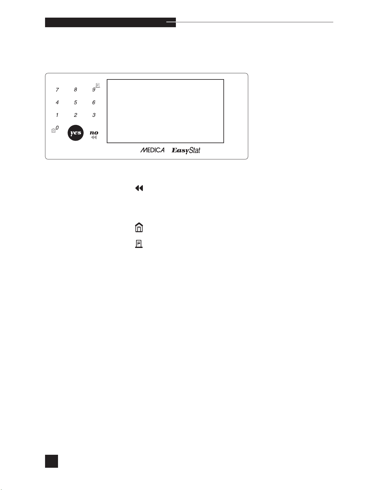
Keypad
Press to correct an entry or return to the previous screen.
In addition to numerical inputs, the 0 and 9 keys each have one
additional function.
Press to return to HOME MENU.
Press to advance printer paper.
10
Page 17
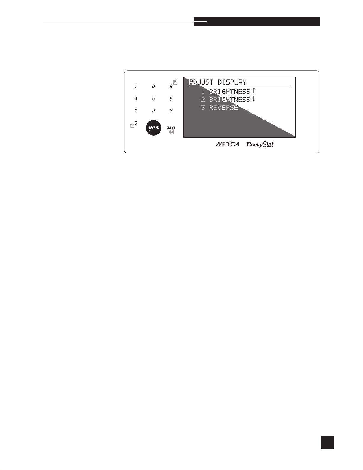
Display
To adjust the display, proceed to the SECOND MENU and select
ADJUST DISPLAY. Press the number 1 or number 2 keys to
adjust the brightness. Press the number 3 key to reverse the contrast of
the display.
a n a l y z e r l a y o u t
r
11
Page 18
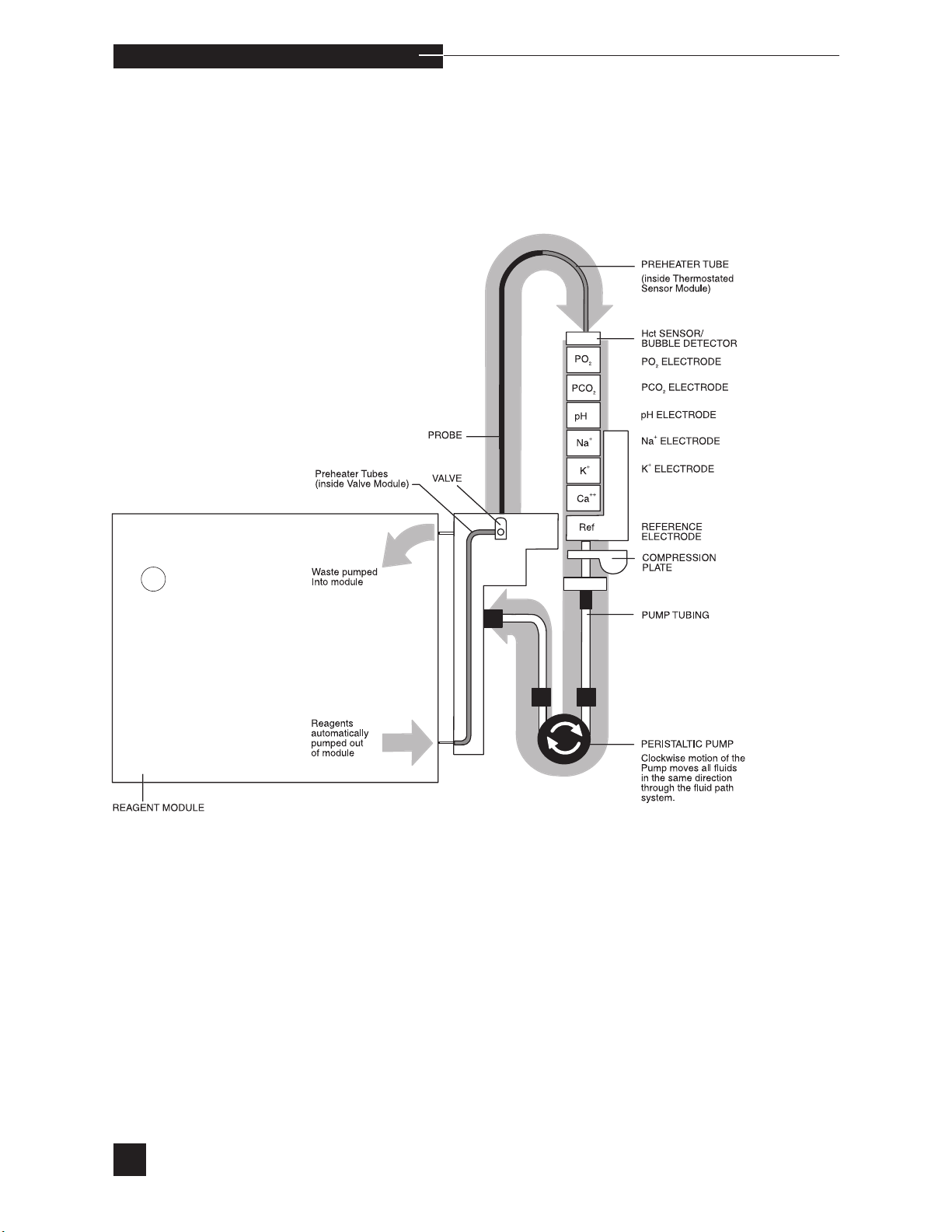
a n a l y z e r l a y o u t
Fluid Path / Module Description
Ca++/Cl- ELECTRODE
s Cl
12
-
electrode should be installed when Cl- mode is selected.
Page 19
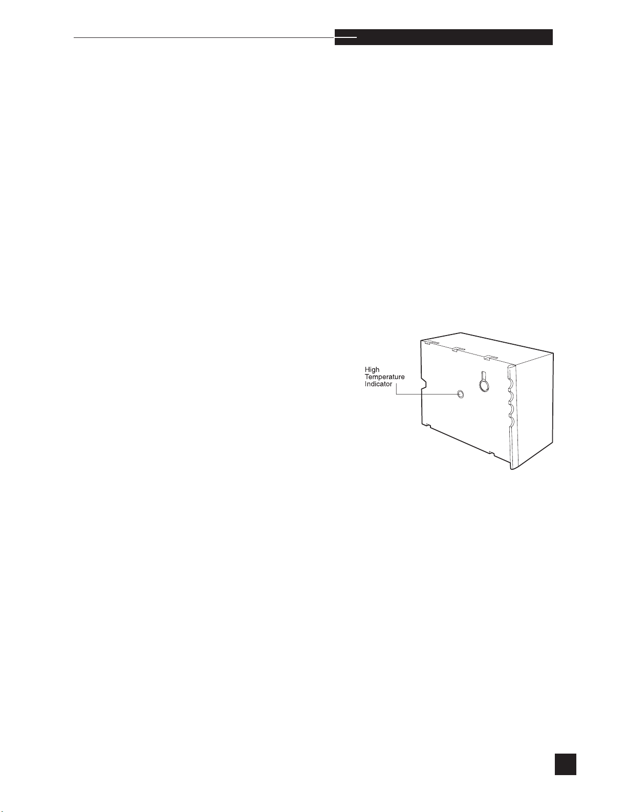
Reagent Module
Disposable module contains all reagents and a waste container.
The reagent module is equipped with an electronic chip which contains
encoded information which is automatically read by the analyzer upon
installation of the reagent module. This information includes:
l
calibrant concentrations for pH, PCO2, PO2, Hct, Na+, K+, Ca++,
and Cl-;
l
current reagent module serial number and installation date;
l
analyzer serial number that the reagent module was first installed
on;
l
reagent volume % remaining with the number of days remaining
before calibrants expire.
a n a l y z e r l a y o u t
r
Prior to installation, a reagent module must be stored at room temperature for a minimum of four hours. When the center of the indicator on the back of the reagent module becomes dark, the module has
been exposed to excessive heat and must not be used.
After initial installation, the reagent module is functional for a limited
number of days (see reagent module insert sheet). After each calibration, the reagent module % and days remaining are printed. When
the reagent module has 0% remaining, RGNT MODULE EMPTY
is displayed. If the reagent module has exceeded the allowable usage
period, RGNT MODULE EXPIRED is displayed. Both of
these conditions require reagent module replacement.
Valve Module
s
s
Selects reagents from the reagent module, preheats and directs them
through the probe.
Sensor Module
Thermostated housing for the electrodes. The sampler containing the
probe is attached. A bubble detector above the electrodes detects fluid
or air in the fluid path.
13
Page 20
3. Analyzer Installation
Unpacking
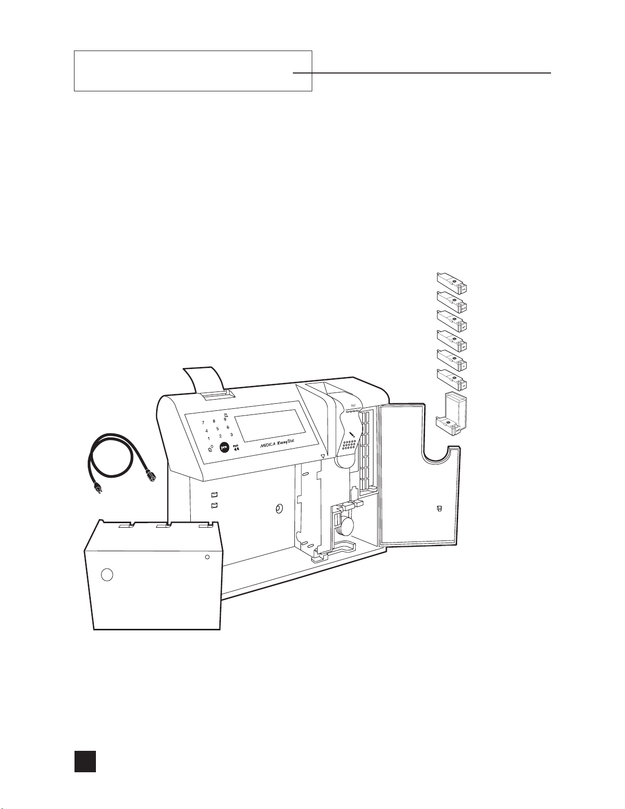
Carefully remove the EasyStat analyzer and accessories from the
shipping containers and place them on a solid work surface. Visually
inspect for any damage sustained during shipment. If damage is
found, or if items are missing, promptly notify your dealer.
PO2 Electrode
PCO2 Electrode
pH Electrode
Na+ Electrode
K+ Electrode
Power Cord
Reagent Module
Ca++/Cl- Electrode
Reference Electrode
EasyStat Analyzer with Valve Module, Sensor
Module, Pump Tubing
s Cl
14
-
electrode should be installed when Cl- mode is selected.
Page 21
a n a l y z e r i n s t a l l a t i o n
Location
The analyzer operates in the ambient (room) temperature range from
15° to 30°C (59° to 86°F) with a maximum relative humidity of 85%,
and a barometric pressure range of 500-800 mmHg. The analyzer
must operate in a normal atmosphere of 21% oxygen. Choose a location which provides good ventilation and is free from vibration and
electrical interferences.
r
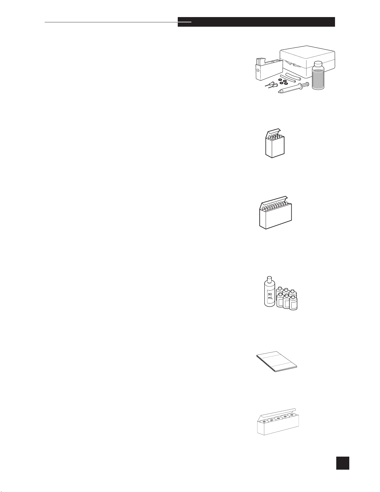
Troubleshooting Kit
Quality Controls
Hct Controls, Bi-Level
Daily Cleaning Solution Kit
Operatorʻs Manual
Operator’s Manual
Printer Paper
15
Page 22
11
o
C
tory-set
we
r Voltage Settin
a n a l y z e r i n s t a l l a t i o n
Power Up
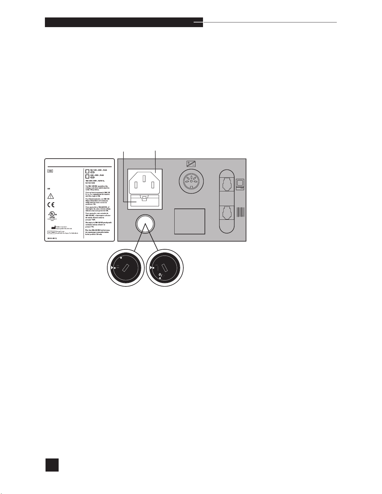
Before connecting the analyzer to power, confirm that the factory set
voltage (110V or 220V) of the EasyStat analyzer matches the grounded outlet supplying the power. When factory set to 110V, the installed
fuses are 0.8 amp. When factory set to 220V, the installed fuses are
0.4 amp. If it is necessary to switch the EasyStat voltage setting, the
correct fuses must be installed. Refer to Replace Components/Fuses,
or contact your EasyStat dealer.
\EDIC@
use Holder
220
Power Cord Socket
A
r
HDo not install reagent module or electrodes at this time.
When the analyzer is powered up, the display will prompt you to set
the correct date and time.
16
Page 23
1 QC
2 NORMAL
3 CRITICAL
4 AMR
REFERENCE LIMITS
1 PO2 / PCO2 / BP mmHg
2 Na
+ / K+
/ Ca
++
mmol/L
3 Hct %
4 Hb
g/dL
5 BC CHECKSUM OFF
CONFIRM ?
CONFIGURATION 1/2
1 CAL FREQUENCY 8 HRS
2 AUTO STANDBY OFF
3 TEMPERATURE C
4 Rili-BAK OFF
5 AMR OFF
CONFIRM ?
CONFIGURATION 2/2
a n a l y z e r i n s t a l l a t i o n
Date/Time
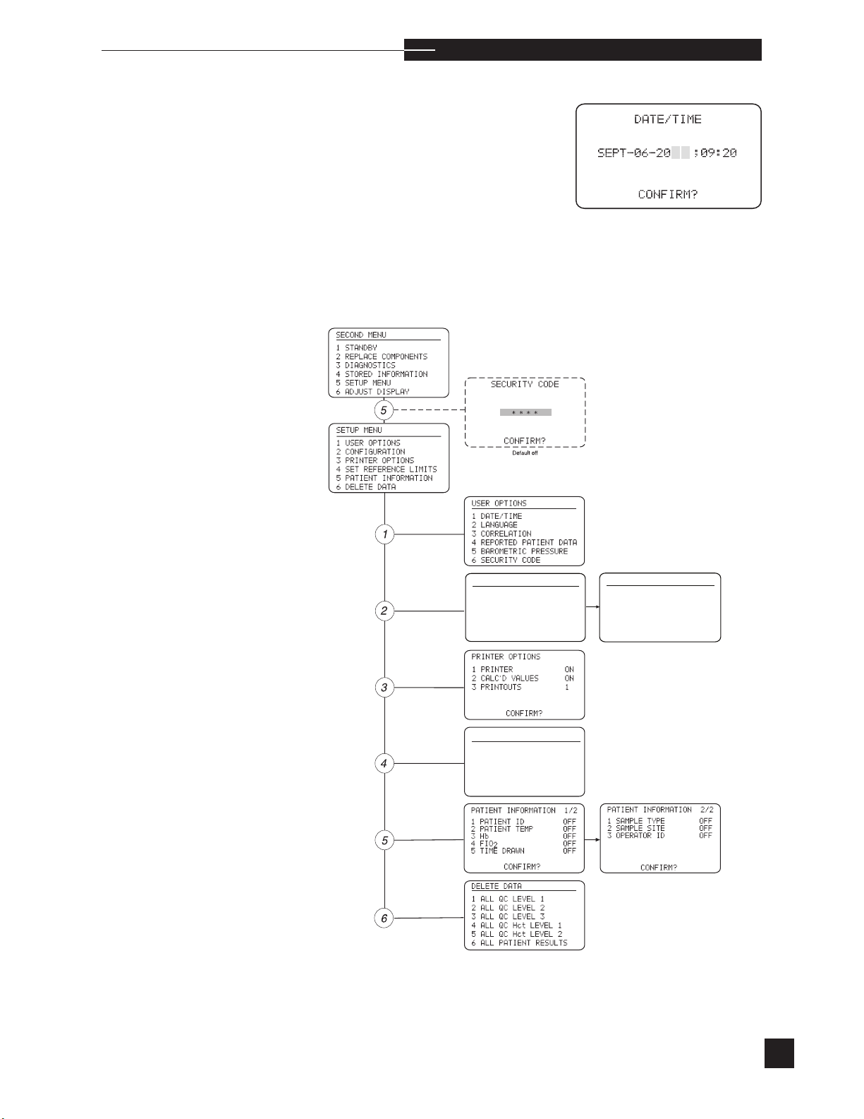
The EasyStat analyzer has a 24 hour internal clock.
At the DATE/TIME display, press NO to change the month and
YES to accept. Press the number keys to enter the day, year and time,
accepting each with YES, or pressing NO to move to the left to correct
an entry. Press YES to CONFIRM? to accept the DATE/TIME.
r
For optional operator-selected settings, proceed to SECOND
MENU, SETUP MENU.
s
sCa
++
is replaced with Cl- when Cl- mode is selected.
17
Page 24
a n a l y z e r i n s t a l l a t i o n
Components
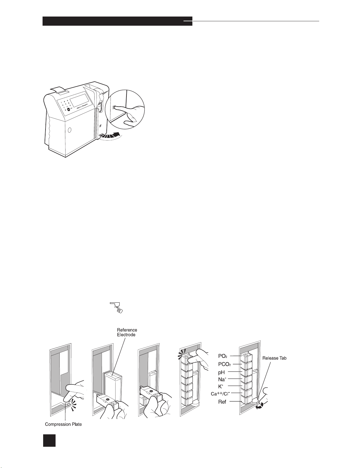
Press the raised dots on the access door to open, and familiarize
yourself with the EasyStat analyzer components. The access door must
remain closed during operation to maintain a temperature of 37.0º C.
Prior to installing the electrodes, select ELECTRODES under
H
REPLACE COMPONENTS in the SECOND MENU.
Electrodes
To install the electrodes, push the compression plate down until the
latch locks into the open position.
Install the reference electrode first, pushing it in above the compression
plate. The handle snaps into the sensor module.
Next, install the Ca++, K+, Na+, pH, PCO2 and PO2 electrodes,
beginning from the bottom and proceeding upward. Each handle
should snap into the sensor module. The electrodes are keyed to
assure correct placement. DO NOT FORCE. Refer to the illustration
and the access door label for correct electrode order and location.
Release the compression plate to compress the electrodes within the
sensor module.
18
Page 25
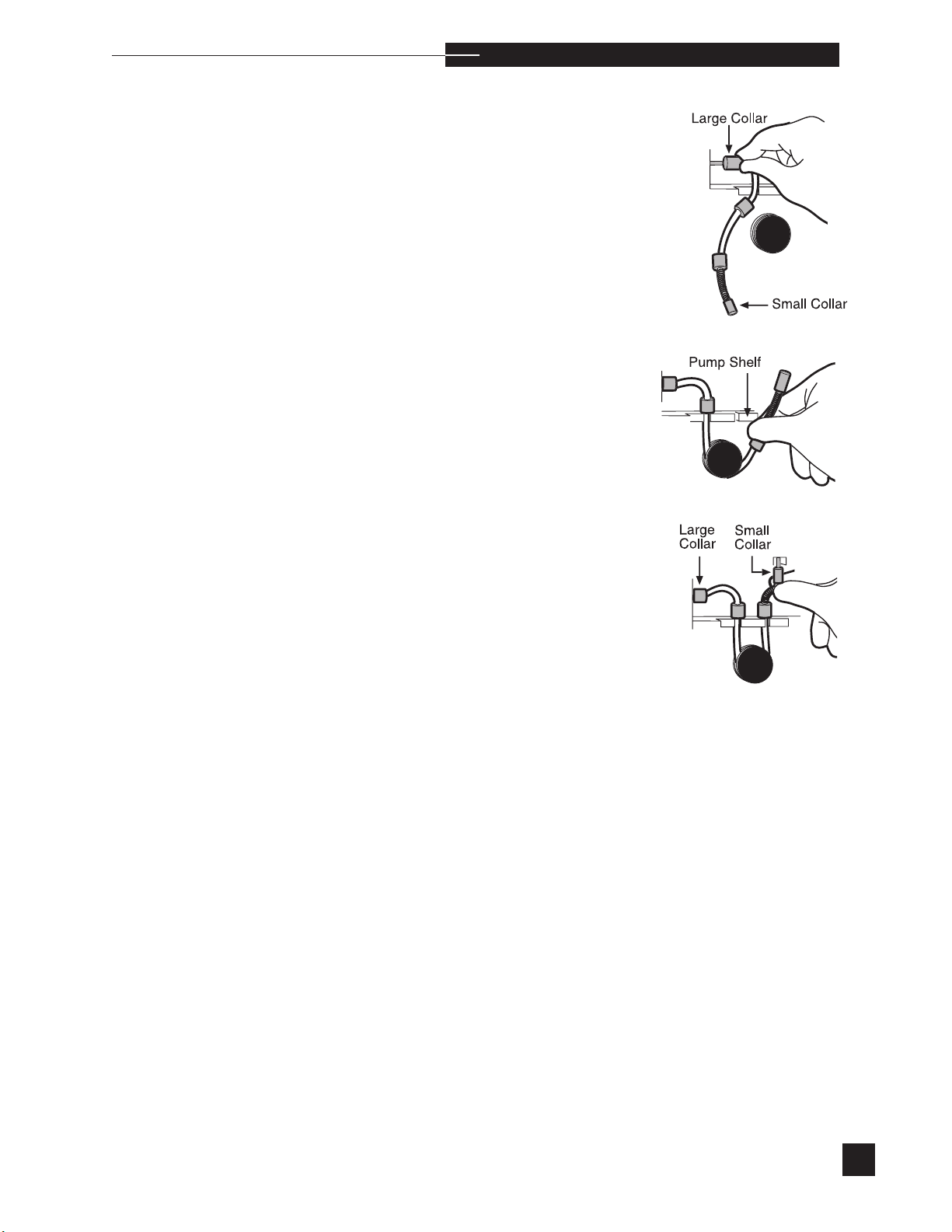
Pump Tubing
Install the pump tubing.
a n a l y z e r i n s t a l l a t i o n
r
Push the two middle collars completely into the back of the slots on
the pump shelf.
s
19
Page 26
a n a l y z e r i n s t a l l a t i o n
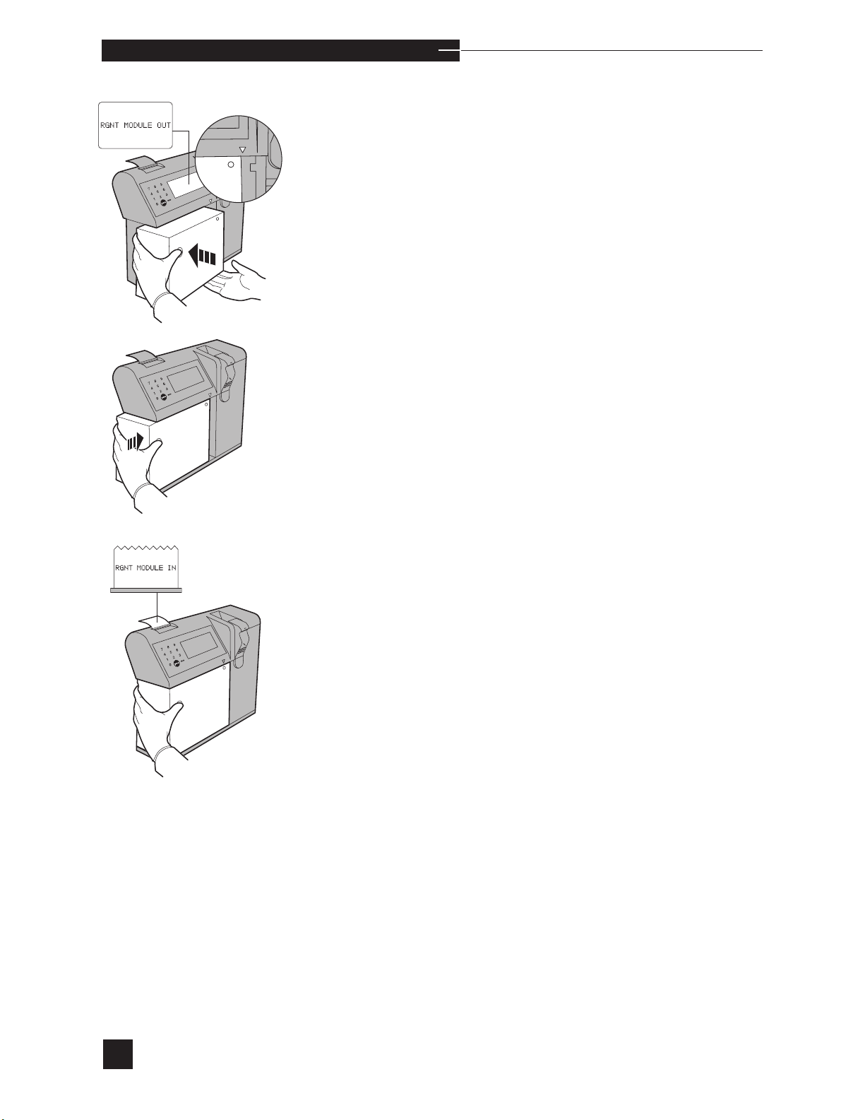
Reagent Module
Place the reagent module into the front of the analyzer. The guide
arrow must point to the right side of the reagent module. Push the
module straight back, then firmly to the right to lock it into place
against the valve module. When correctly installed, the message
RGNT MODULE IN is printed. When the reagent module is
installed, press yes to CONFIRM?.
20
Page 27
a n a l y z e r i n s t a l l a t i o n
r
When the installed reagent module has less than 10% remaining, the
HOME MENU display will flash the % remaining. Prepare to install
a new reagent module when the % remaining reaches zero.
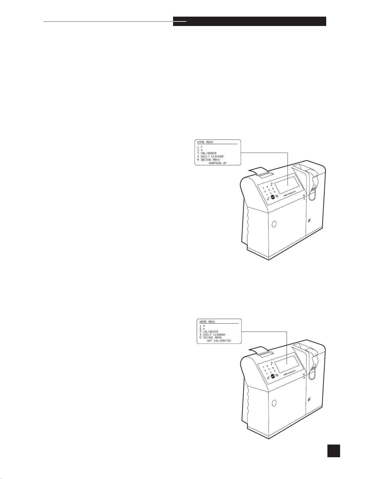
When all components are installed, confirm that the access door
is closed. WARMING UP appears at the bottom of the HOME
MENU display. When the sensor module reaches 37.0°C and the
valve module reaches 39.0°C (approximately 30 minutes from a cold
start) the WARMING UP message disappears. Calibration can now
be performed. Refer to Calibrate in Operating the Analyzer for further
instructions.
s
New electrodes require a short stabilization period to prevent drift
errors. This stabilization is minimized by the analyzer, which performs
calibrations every hour for 8 hours. After this stabilization period,
the analyzer will calibrate at the calibration frequency selected under
CAL FREQUENCY in the CONFIGURATION section of the
SETUP MENU.
s
21
Page 28
LIFT SAMPLER TO
ANALYZE
2
2
Hct Na
Ca
TIO
HOME MENU
2
3 CALIBRATE
4 DAILY CLEANER
5 SECOND MENU
HOME MENU
ANALYZE SAMPLE
2
ANALYZE QC
3 CALIBRATE
4 DAILY CLEANER
5 SECOND MENU
SLOPES
pH
61.02
PCO253.17
O
2
1
Hct.88
Na
58.98
K
61.50
Ca
24.62
CALIBRATION
BUBBLE
DETECTOR
CAL
air fluid
BD PASS 171 030
PUMP CAL
PUMP PASS 0799
REAGENT
MODULE
STATUS
021%, 15 DAYS
JUNE-05-20
;13:35
4. Operating the Analyzer
Calibrate
The EasyStat analyzer requires a two-point calibration after installation and warm-up. Automatic two-point calibrations occur at
pre-selected intervals chosen under CAL FREQUENCY in the
CONFIGURATION section of the SETUP MENU. Automatic
Hct calibrations are included in each two-point calibration. Ondemand two-point calibrations can be initiated in the HOME MENU
by choosing CALIBRATE. If not calibrated, the HOME MENU
P
3.0
only displays options 3, 4 and 5.
The ACCESS DOOR must be closed during warm-up, calibration, and sampling.
Select CALIBRATE to perform a two-point calibration and prepare
the EasyStat analyzer for sample analysis. The analyzer displays the
calibration status. Bubble detector and pump cal results are printed
at completion. After a successful calibration, the analyzer displays
and prints the slope of each electrode, the % of calibrants remaining,
and the number of days before expiration. After completion of a successful calibration, the analyzer displays LIFT SAMPLER TO
ANALYZE pH PCO2 PO2 Hct Na+ K+ Ca++.
22
s
++
Ca
is replaced with Cl- when Cl- mode is selected.
Page 29

o p e r a t i n g t h e a n a l y z e r
r
In addition to calibration, analysis of quality control material is
required to verify the performance of the EasyStat analyzer. This procedure is outlined under Analyze QC in this chapter.
The EasyStat analyzer is factory set to perform automatic twopoint calibrations every eight hours. To change the setting, proceed
to the SECOND MENU and select SETUP MENU, then
CONFIGURATION, and CAL FREQUENCY.
A two-point calibration can be interrupted to perform stat samples.
Press NO and STOP CALIBRATION? is displayed. Press
YES and SYSTEM CALIBRATION INTERRUPTED is displayed before returning to the HOME MENU for sample analysis.
When the sampler is raised during calibration, the display prompts
you to
RETURN SAMPLER
the closed position, the message SYSTEM
INTERRUPTED
HOME MENU.
appears for 10 seconds before returning to the
No more than three interruptions are permitted dur-
. When the sampler is returned to
CALIBRATION
ing a scheduled calibration.
When an electrode does not calibrate successfully, that parameter will
not appear on the screen. A parameter will not be displayed or printed if PATIENT DATA is turned off under USER OPTIONS
in the SETUP MENU. The reporting of specific analytes is disabled under REPORTED PATIENT DATA. No sample results
(including dependent calculated results) are given for that electrode.
Refer to ELECTRODES in Troubleshooting.
s
The analyzer will display any error detected during calibration. If an
error occurs, the analyzer will automatically attempt a second twopoint calibration. If this fails, troubleshooting may be required.
During each sample analysis, the EasyStat analyzer performs a onepoint calibration.
23
Page 30
y
yes
y
o
SAMPLE # XXX
ANALYZING SAMPLE
SAMPLE # XXX
PROBE IN SAMPLE?
SAMPLE # XXX
REMOVE SAMPLE
RETURN SAMPLER
SAMPLER TO
LIFT SAMPLER TO
ANALYZE
2
2
Hct Na
K Ca
y
yes
y
HOME MENU
ANALYZE SAMPLE
2 ANALYZE QC
3 CALIBRATE
4 DAILY CLEANER
5 SECOND MENU
o
SAMPLE # XXX
ASPIRATING...
CALCULATED VALUES
SCREENS
RETURN SAMPLER
ONE MOMENT...
ANALYSIS RESULTS #001
pH
7.403
PCO232.5 mmH
g
PO
2
mmH
g
Hct45%
Na.1
mmol/L
K
4.02 mmol/L
Ca.33 mmol/L
o p e r a t i n g t h e a n a l y z e r
Analyze Sample
1
n
24
n
The ACCESS DOOR must be closed during sample analysis.
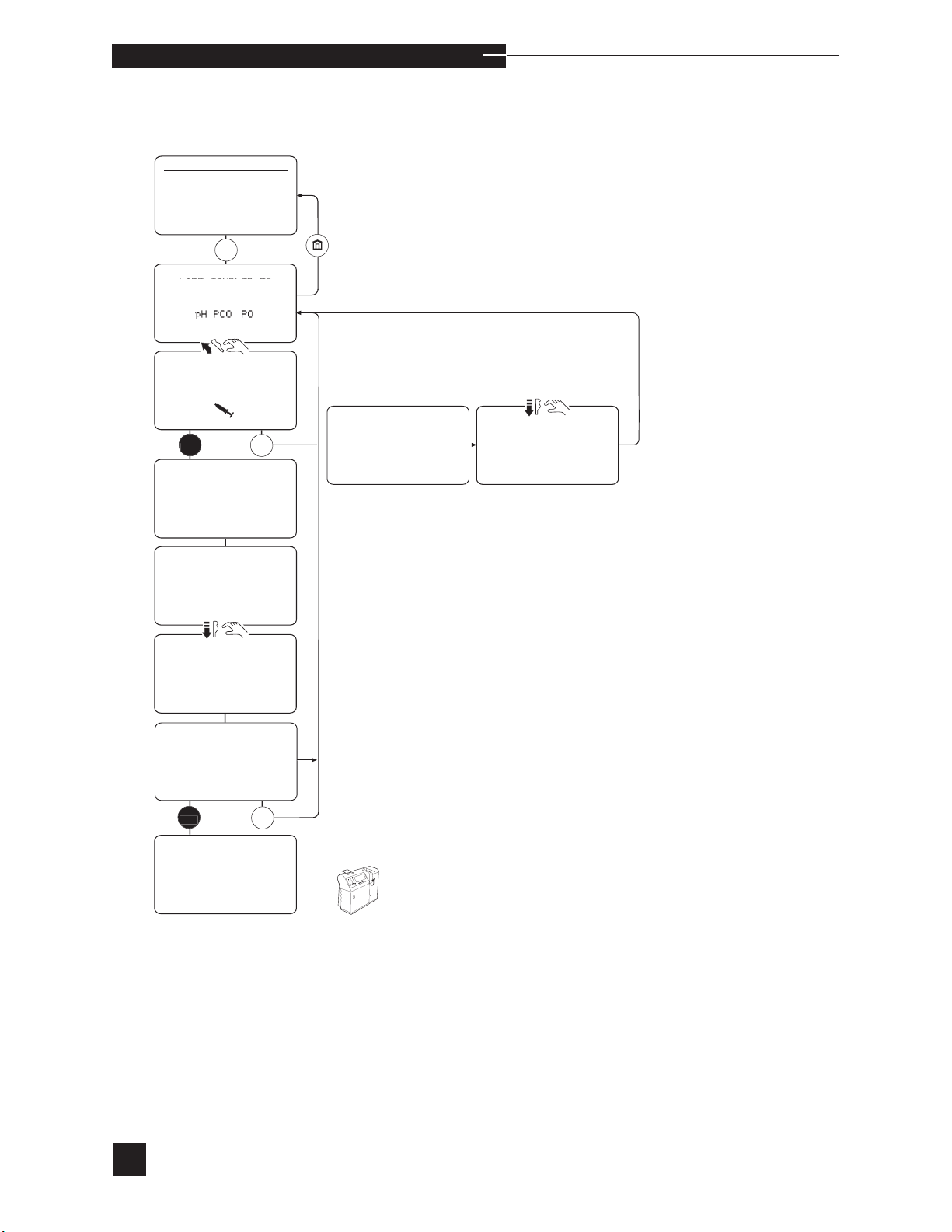
Select ANALYZE SAMPLE. The display shows LIFT
SAMPLER TO ANALYZE pH PCO2 PO2 Hct Na+
K+ Ca++. When an electrode does not calibrate successfully, that
parameter will not be displayed on the screen. No sample results
(including dependent calculated results) are given for that electrode.
Refer to ELECTRODES in Troubleshooting.
sCa
++
is replaced with Cl- when Cl- mode is selected.
Page 31
o p e r a t i n g t h e a n a l y z e r
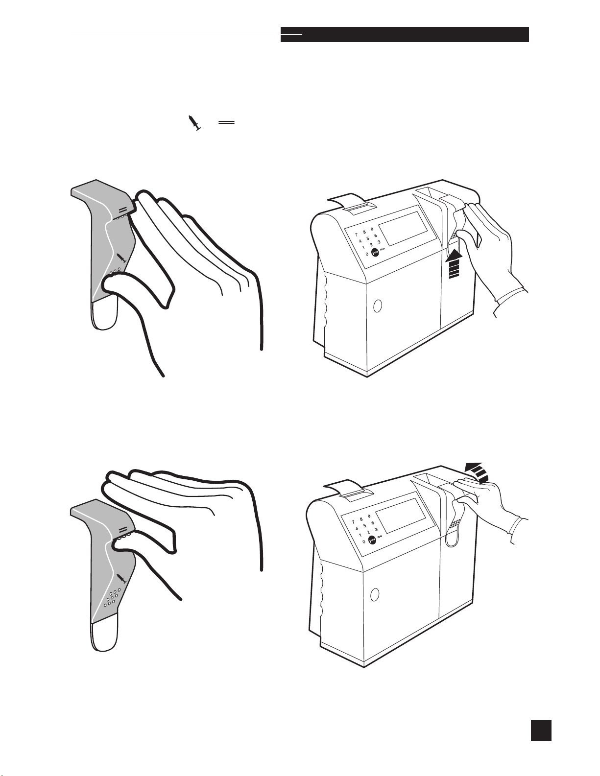
The EasyStat sampler is designed for two separate sample entry
modes. To select the sampling mode, place your thumb on the
raised dots under the corresponding symbol, and push up to lift
the sampler for syringe or capillary samples.
Thumb placement for syringe samples. Push up.
r
Thumb placement for capillary samples. Push up.
25
Page 32
o p e r a t i n g t h e a n a l y z e r
Syringe Mode
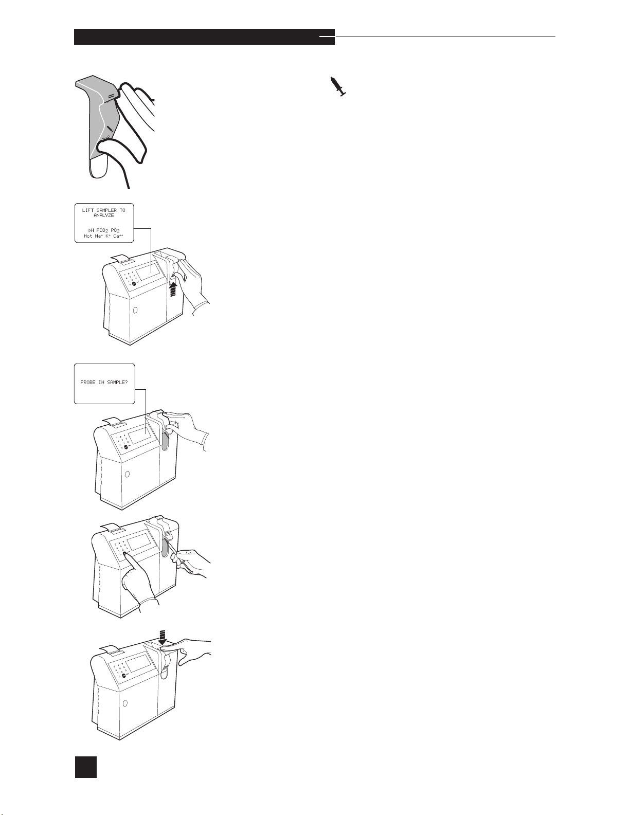
To analyze samples from blood gas syringes (120 µL minimum), lift
the sampler until PROBE IN SAMPLE? is displayed.
When using a syringe, it is important that the sample probe does
H
not touch the plunger of the syringe. If this occurs, the resulting
vacuum can damage the electrodes. The air in the syringe should be
expelled immediately and completely upon sampling. Samples unexposed to air and preserved in ice water must be analyzed within 30
minutes.
Place the probe in the sample and press YES. Hold the syringe in
place, keeping the probe submerged in the sample until REMOVE
SAMPLE RETURN SAMPLER is displayed.
Push the sampler down into the closed position. If PATIENT
INFORMATION settings are turned ON in the SETUP MENU,
the ENTER PATIENT DATA? screen displays for 30 seconds.
Press YES to enter patient information (2 minutes is allowed), or NO to
continue. Analysis begins when the sample is automatically positioned
inside the electrodes.
26
Page 33
o p e r a t i n g t h e a n a l y z e r
r
If the sampler is not returned within two minutes of aspiration the
sample will be pumped to waste
Sample analysis can be interrupted by pressing NO. STOP
ANALYSIS? is displayed. Press YES and ANALYSIS
INTERRUPTED is displayed before returning to the LIFT
SAMPLER TO ANALYZE pH PCO2 PO2 Hct Na+
K+ Ca++ screen.
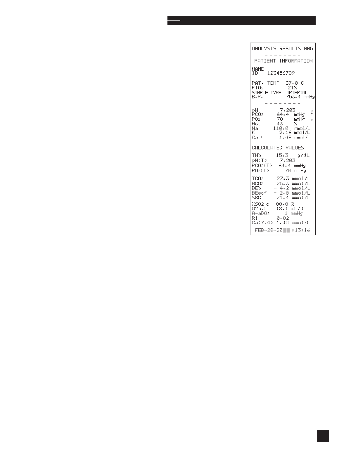
When analysis is complete, the measured results are printed with the
current sample number. The measured results are reported in mmHg
for blood gas parameters and mmol/L for electrolytes. When alternate units are on (refer to CONFIGURATION in the SETUP
MENU), blood gas results are expressed in KPa and electrolytes are
expressed in mEq/L.
Results are automatically printed after each analysis if the printer is
turned on under CONFIGURATION in the SETUP MENU. The
measured results are compared to the normal and critical limits set
under SET REFERENCE LIMITS in the SETUP MENU.
When analysis results are in the critical range, they are flagged as
low (↓↓) or high (↑↑) on both the display and the printout. Patient
results that are outside the normal range, and not in the critical range
will be flagged as low (↓) or high (↑) on the display and printout. If
any result is not within the analyzer’s measurement range, the result
is displayed and printed as — e.g., pH < 6.50 ↓↓ or pH > 8.00 ↑↑.
The display will show < 6.50 ↓↓ or > 8.00 ↑↑ blinking on and off.
The analyzer displays CALCULATED VALUES?. The calculated
results print with the measured results. View the calculated values by
pressing YES.
ss
ss
sCa
++
is replaced with Cl- when Cl- mode is selected.
27
Page 34

o p e r a t i n g t h e a n a l y z e r
s
ecf
-
,
3
,
Calculated values for THb, pH(T), PCO2(T), PO2(T), TCO2, HCO
and BE
display screen. Press YES to view the calculated results for BE
SBC, %SO2c, O2ct, A-aDO
results use the following default values, if patient values were not
entered (see PATIENT INFORMATION screen in the SETUP
MENU):
Patient Temp 37°C
Hb 14.5 g/dL
FIO2 21%
User entered correlation values are applied to the measured results to
provide the displayed and printed results. If correlations are applied,
reported results will be printed as CORRELATION APPLIED
results. Refer to CORRELATION under USER OPTIONS in
the SETUP MENU for more information.
are displayed. MORE DATA? appears at the top of the
b
RI and Ca++ (7.4). The calculated
2,
28
s In Cl
-
mode, Ca++ (7.4) is replaced with Anion Gap.
Page 35
o p e r a t i n g t h e a n a l y z e r
Capillary Mode
To analyze samples from capillary tubes (95 µL minimum), lift the
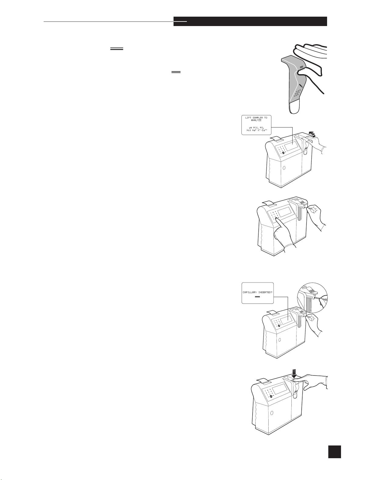
sampler until
CAPILLARY INSERTED?
is displayed.
Note: Use only the Medica capillary kit. Use of other capillary
tubes may result in erroneous results or damage to the analyzer
and electrodes.
The capillary should be filled entirely with no visible air bubbles.
H
Seal the ends with caps. Analyze the capillary sample within 10
minutes of sampling.
r
Insert the capillary tube into the capillary port. When inserted,
press YES and the sample is aspirated.
RETURN SAMPLER is displayed.
REMOVE CAPILLARY
Push the sampler down into the closed position. If PATIENT
INFORMATION settings are turned ON in the SETUP MENU,
ENTER PATIENT DATA? screen displays for 30 seconds.
the
Press YES to enter patient information (2 minutes is allowed), or
NO to continue. Analysis begins when the sample is automatically positioned inside the electrodes.
Sample analysis can be interrupted by pressing NO.
ANALYSIS? is displayed. Press YES and ANALYSIS
INTERRUPTED is displayed before returning to the LIFT
SAMPLER TO ANALYZE pH PCO2 PO2 Hct Na
++
Ca
screen.
STOP
+ K+
s
sCa
++
is replaced with Cl- when Cl- mode is selected.
29
Page 36
o p e r a t i n g t h e a n a l y z e r
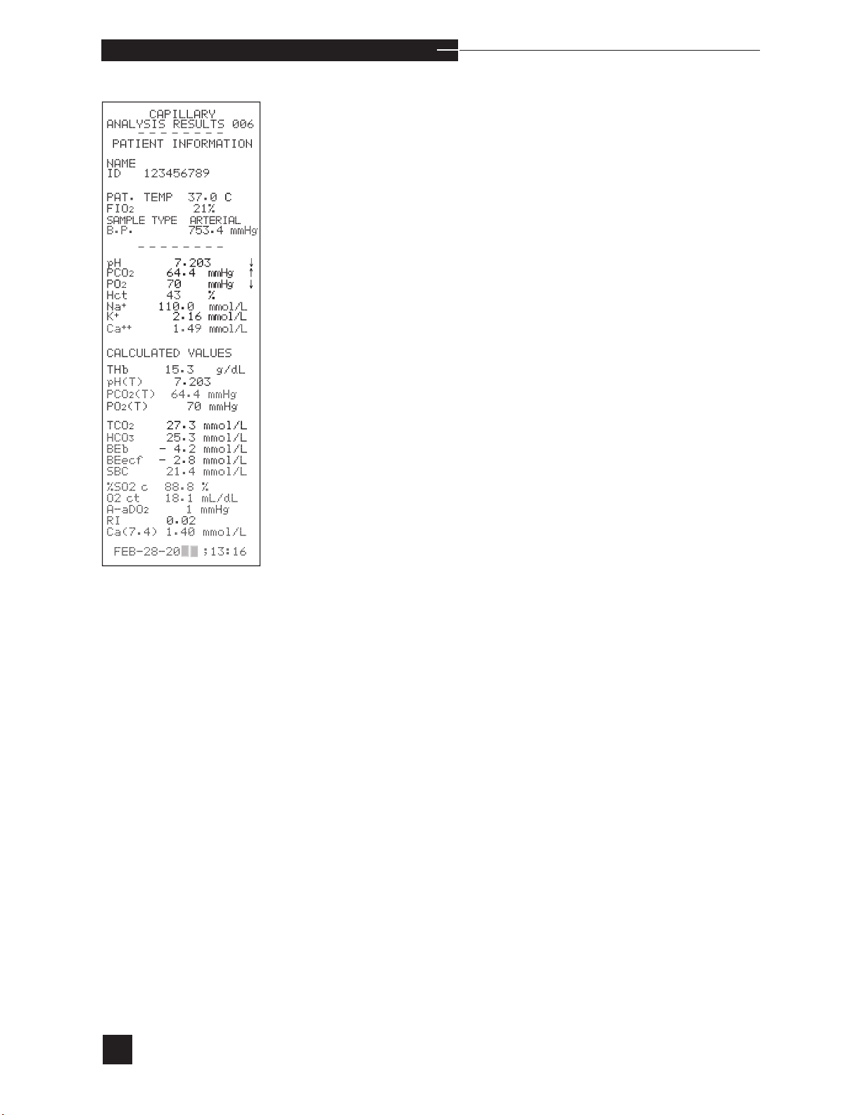
When analysis is complete, the measured results are printed with the
current sample number. The measured results are reported in mmHg
for blood gas parameters and mmol/L for electrolytes. When alternate units are on (refer to CONFIGURATION in the SETUP
MENU ), blood gas results are expressed in KPa and electrolytes are
expressed in mEq/L.
Results are automatically printed after each analysis if the printer is
turned on under CONFIGURATION in the SETUP MENU. The
measured results are compared to the normal and critical limits set
under SET REFERENCE LIMITS in the SETUP MENU.
When analysis results are in the critical range, they are flagged as
low (↓↓) or high (↑↑) on both the display and the printout. Patient
results that are outside the normal range, and not in the critical range
will be flagged as low (↓) or high (↑) on the display and printout. If
any result is not within the analyzer’s measurement range, the result
is displayed and printed as — e.g., pH < 6.50 ↓↓ or pH > 8.00 ↑↑.
The display will show < 6.50 ↓↓ or > 8.00 ↑↑ blinking on and off.
30
Page 37

o p e r a t i n g t h e a n a l y z e r
The analyzer displays CALCULATED VALUES?. The calculated results are printed with the measured results. View the calculated
values by pressing YES. Calculated values for THb, pH(T), PCO
(T), TCO2, HCO
PO
2
-
, and BEb are displayed. MORE DATA?
3
(T),
2
appears at the top of the display screen. Press YES to view the calculated results for BE
, SBC, %SO2c, O2ct, A-aDO2, RI, and Ca++
ecf
(7.4). In Cl- mode, Ca++ (7.4) is replaced with Anion Gap.The calculated results use the following default values, if patient values were not
entered (see PATIENT INFORMATION screen in the SETUP
MENU):
Patient Temp 37°C
Hb 14.5 g/dL
21%
FIO
2
User entered correlation values are applied to the measured results to
provide the displayed and printed results. If correlations are applied,
reported results will be printed as CORRELATION APPLIED
results. Refer to CORRELATION under USER OPTIONS in
the SETUP MENU for more information.
r
s
31
Page 38
y
yes
y
y
yes
y
o
ANALYZE QC
LEVEL
2 QC LEVEL
2
3 QC LEVEL
3
4 Hct Level
5 Hct Level
2
6 PROFICIENCY
HOME MENU
ANALYZE SAMPLE
2 ANALYZE QC
3 CALIBRATE
4 DAILY CLEANER
5 SECOND MENU
QC LEVEL
LOT # XXXXXXXX
LIFT SAMPLER TO
ANALYZE CONTROL
QC LEVEL
LOT # XXXXXXXX
PROBE IN CONTROL?
QC LEVEL
LOT # XXXXXXXX
ASPIRATING...
QC LEVEL
LOT # XXXXXXXX
REMOVE CONTROL
RETURN SAMPLER
QC LEVEL
LOT # XXXXXXXX
ANALYZING CONTROL
ONE MOMENT...
RETURN SAMPLER
QC LEVEL
pH
X.XXX
PCO
2
g
PO
g
Na
XXX.X mmol/L
K
X.XX mmol/L
Ca
X.XX mmol/L
STORE RESULTS?
o p e r a t i n g t h e a n a l y z e r
Analyze QC
QC
XX.X mmH
XXX mmH
no
n
The ACCESS DOOR must be closed during analysis.
32
Page 39

o p e r a t i n g t h e a n a l y z e r
As with all clinical instrumentation, the performance of the EasyStat analyzer
must be monitored using quality control samples. Each laboratory should establish their own quality control program. Medica requires the use of quality controls every day patient samples are analyzed and after any troubleshooting.
r
Medica controls are designed to contain pH, PCO
, PO2, Na+, K+, Ca++,
2
and Cl- values that are within the typical patient population. Each lot of
EasyStat control contains an insert sheet indicating the expected ranges for
pH, PCO
, PO2, Na+, K+, Ca++, and Cl-. Using the 3 levels of controls as
2
part of the laboratory quality control program will aid in verifying analyzer
performance. If controls have results outside the expected ranges, the performance of the analyzer may not be optimum. If necessary, corrective action
should be taken before reporting patient results. Factors that can shift control
results from the insert sheet ranges are:
l
control material temperature when ampule is opened (PO2 control
values increase by 1.3% for every 1°C decrease in storage temperature from 23°C or PO2 control values decrease by 1.3% for every
1°C increase in storage temperature from 23°C)
l
elevation (PO2 control values decrease by 1% for every 1000 feet
(305m) above sea level)
l
correlation factors applied to quality control samples
The hematocrit controls are assayed quality control materials used to monitor
the measurements of hematocrit in the EasyStat analyzer. Electrical conductivity methodologies are used to determine hematocrit.
Medica hematocrit controls are designed to contain hematocrit values that are
within the typical patient population. Each lot of control contains an insert sheet
indicating the expected ranges for hematocrit. The values for each control analyte are based on multiple determinations performed on randomly selected samples from each lot. The expected range and mean values shown are provided as
a guide in evaluating analyzer performance. The mean value established should
fall within the expected value range shown on the chart provided.
As part of a good quality control program, each laboratory should establish
their own ranges for each lot of controls over multiple days. The ranges must
be examined for clinical significance.
Once established, enter the limits into the EasyStat analyzer under SET
REFERENCE LIMITS in the SETUP MENU.
The EasyStat stores quality control results for 3 levels (a maximum of 93 for
each level) when control samples are analyzed through ANALYZE QC.
The results for pH, PCO
, PO2, Hct, Na+, K+, Ca++, and Cl- are compared
2
to the quality control reference limits previously entered for the chosen level
of quality control. Levey-Jennings charts can be printed to document the performance of the stored quality control sample results over time.
33
Page 40

o p e r a t i n g t h e a n a l y z e r
QC REFERENCE LIMITS
1 LEVEL 1
2 LEVEL 2
3 LEVEL 3
4 Hct LEVELS
s
Quality Control Settings
Quality control limits and lot numbers must be entered for each new
lot of quality controls, before selecting ANALYZE QC from the
HOME MENU. Proceed to the SECOND MENU and select
SETUP MENU, then REFERENCE LIMITS. Select QC,
then LEVEL 1, LEVEL 2, or LEVEL 3, or Hct
Levels.
It is recommended that any stored quality control results be deleted
prior to entering information for a new lot of quality controls. Refer to
DELETE DATA in the SETUP MENU.
Select LEVEL 1, 2, 3, or Hct LEVELS to enter the limits
and lot number each time a new lot of controls is introduced. The display lists pH, PCO
then use the number keys to enter the new lot number and limits. Press
YES to confirm each and move to the next entry. When all entries are
complete, press YES to CONFIRM?. If NO is pressed as a response
to CONFIRM?, the settings can be corrected. Repeat for each level
of control. To proceed with quality control analysis, press
to HOME MENU.
, PO2, Hct, Na+, K+, or Ca
2
++
limits.* Press NO,
to return
s
s
If RiliBAK feature is on, press NO and use the number keys to enter the
lot number and the target from the package insert. The analyzer calculates the limits using the RiliBAK percent deviation and target value.
The percent deviation or the RiliBAK limits can be changed manually
using the number keypad. Press YES to confirm the entry and advance
to the next entry.
To enter quality control information using the barcode reader, Medica
quality controls must be used.
To enter quality control information using the barcode reader, Select
LEVEL 1, 2, 3, or Hct LEVELS. LOT # is highlighted on the display. Using the barcode reader, scan in the lot number provided on the quality control insert sheet. Next, the parameter
will be highlighted. Scan in the parameter range (verify that the displayed range matches the insert sheet). Repeat for remaining parameters. When all entries are complete, press YES to CONFIRM?.
When NO is pressed as a response to CONFIRM?, the settings can
be corrected. Repeat for each level of control. To proceed with quality
control analysis, press
to return to HOME MENU.
34
s
*Cl- limits will be listed for Cl- (Chloride) mode.
Page 41
Quality Control Analysis
o p e r a t i n g t h e a n a l y z e r
r
Follow the manufacturer’s storage and handling instructions for quality
control material before proceeding with quality control analysis.
The Easy QC materials are aqueous solutions with gasses dissolved in
them along with other components necessary to qualify the electrodes.
Prior to the testing of these materials, careful attention needs to be
paid to the instructions. If the ampules are not prepared and handles
as instructed, erroneous readings may result.
Refer to the insert sheet enclosed in the Easy QC package for proper
handling instructions.
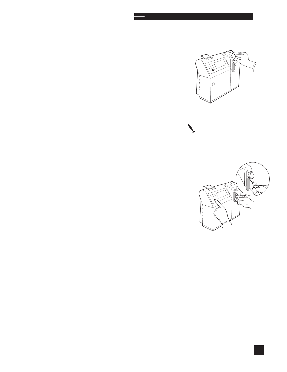
The sampler must be in the syringe mode position.
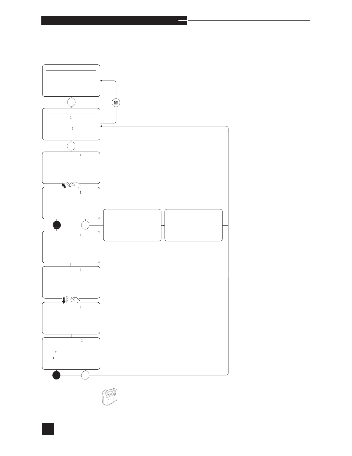
Select ANALYZE QC for Level 1, 2, 3 or Hct. Select the desired
level. Break open the quality control ampule and analyze immediately.
Lift the sampler and PROBE IN CONTROL? is displayed.
Place the probe in the quality control material and press YES. Hold
the ampule in place, keeping the probe submerged in the ampule until
REMOVE CONTROL RETURN SAMPLER is displayed.
Push the sampler down into the closed position. The quality control is
analyzed and results for each parameter are displayed and printed.
Results falling outside the quality control limits are flagged as (↓) low
or (↑) high.
s
Three quality control results for each level are automatically stored
each day when no errors are detected. When more than three of a
control level are performed on the same day, the three most recent
results replace the results previously stored for that day. The EasyStat
analyzer stores up to 93 quality control results for each level.
If a result is outside the limits or an error occurs, a STORE
RESULTS? prompt is displayed. Press YES to store quality control
results, or NO to reject the results.
If selected, quality control correlation factors will be applied to results.
s
s
35
Page 42

o p e r a t i n g t h e a n a l y z e r
Proficiency
To analyze proficiency samples, select PROFICIENCY under
ANALYZE QC. These samples are analyzed without applying cor-
relation values to the measured results, which enables the EasyStat
results to be grouped together on the proficiency program’s interlaboratory reports. The proficiency results are not stored.
Stored QC Information
Select STORED INFORMATION from the SECOND MENU,
then QC RESULTS to view the last quality control results, print QC
statistics or plot QC charts. PRINT QC STATS prints the results
by date, mean, standard deviation, and coefficient of variation for the
stored quality control results. PLOT QC CHARTS prints the stored
quality control results as a Levey-Jennings chart. The statistics are calculated according to the following definitions:
s
A minimum of 5 stored quality control results is required to
calculate statistics.
Definitions
Mean: The mean (x) is the value derived by dividing the sum (Σ)
of the observed values by the number of observations (n) stored in
memory (between 5 and 93 values).
_
SD: The standard deviation (SD) measures dispersion within the
distribution of data stored.
where: SD =
x =
Σ values
n
2
(x-x)
n-1
2
Σ(x-x)
n = number of observations
=
sum of the square of each difference from the mean
36
CV:
The coefficient of variation (CV) is a measure (as a percentage) of the
variation from the mean within the set of stored data.
CV = 100 SD
x
Page 43
3
00000000
008
6
382
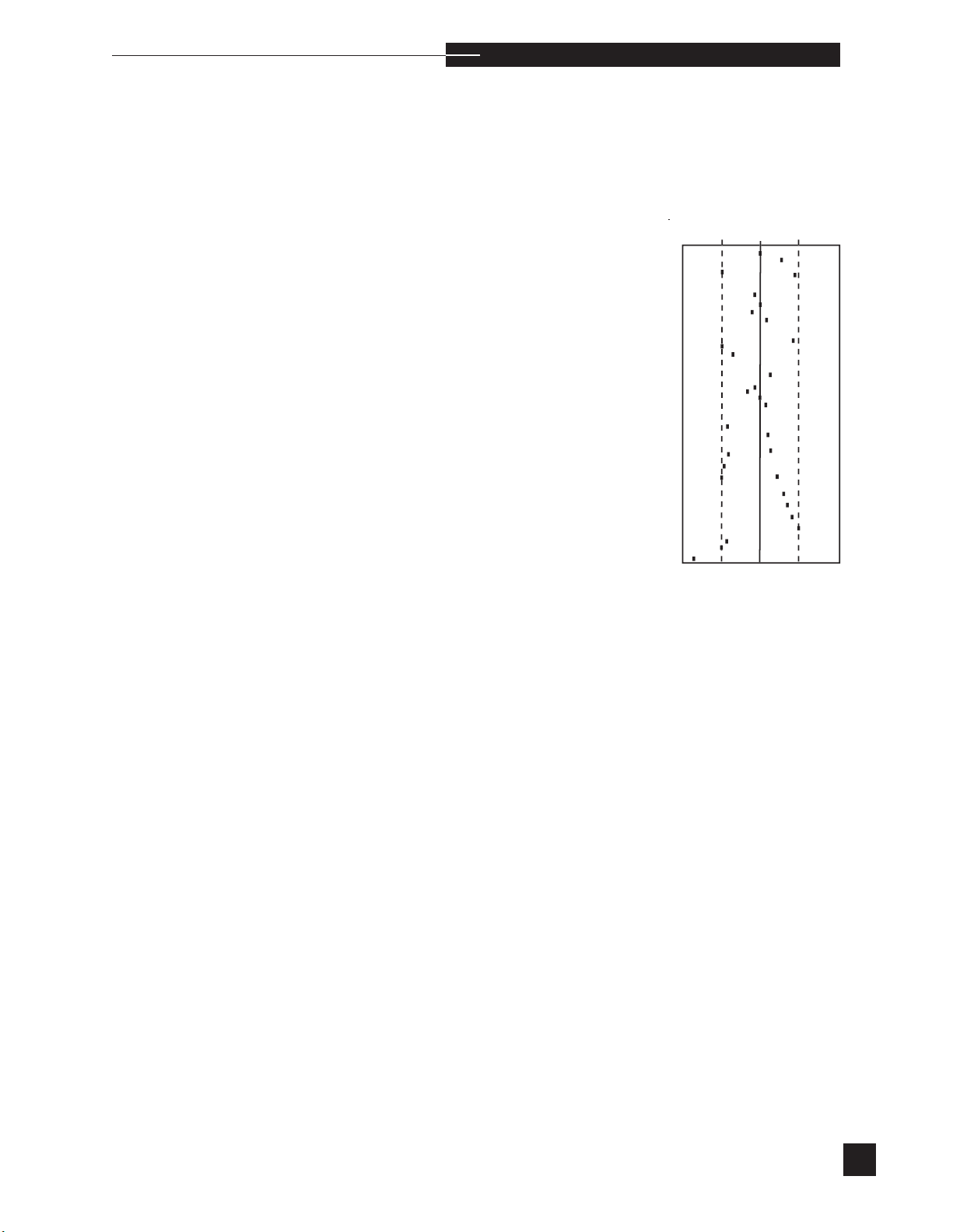
Levey-Jennings Chart:
o p e r a t i n g t h e a n a l y z e r
r
Levey-Jennings charts plot the measured quality control results for each
day. The calculated mean value is shown by the solid, vertical center
line. The +/- 2 SD values are shown by the dashed lines. The limits of
the charts are the mean +/- 4 SD. The Levey-Jennings charts plot data
for the last 31 days. (See example below.)
C
LOT#
D
.
2SD
7.
3
2
1
2SD
7.44
The statistics reported above each chart require a minimum of 5
stored quality control results. The maximum number of stored results is
93 for each level.
s
37
Page 44

o p e r a t i n g t h e a n a l y z e r
Random Errors
An isolated result which falls outside the +/- 3 SD control limits is
classified as a random error. When a single random error occurs,
disregard the result. When there is an increase in the frequency of
random errors, the quality control sampling technique should be
reviewed.
Systematic Errors
A recurring measurable deviation from the mean is classified as a systematic error. One example of a systematic error is when a progressive increase or decrease in control results is noted. Possible causes
are:
• aging or protein contaminated electrode
• bubbles beneath an electrode membrane
• a change in calibrant
• a change in temperature
• a change in quality control material
• aging reference electrode
If the sampling technique is acceptable and random errors continue,
refer to ELECTRODES in Troubleshooting.
38
Page 45

o p e r a t i n g t h e a n a l y z e r
r
Users should follow applicable agency requirements for quality control
testing.
Recommended Material
EasyQC Quality Controls:
Level 1
Level 2
Level 3
Hct Level 1
Hct Level 2
Do not use perfluorocarbon-based control materials on the EasyStat
analyzer. This type of control material will damage the electrodes.
Precautions
Refer to the package insert provided with the quality control material.
Recommended Procedure
Run all control levels each day the analyzer is in use.
future statistical analysis.
Data is stored for
s
s
Use Instructions
Refer to the package insert provided with the quality control material.
Storage and Stability
Refer to the package insert provided with the quality control material.
Handling
Refer to the package insert provided with the quality control material.
Expected Results
Refer to the package insert provided with the quality control material.
39
Page 46
HOME MENU
ANALYZE SAMPLE
2 ANALYZE QC
3 CALIBRATE
4 DAILY CLEANER
5 SECOND MENU
DAILY CLEANER
LIFT SAMPLER TO
USE CLEANER
o p e r a t i n g t h e a n a l y z e r
Daily Cleaner
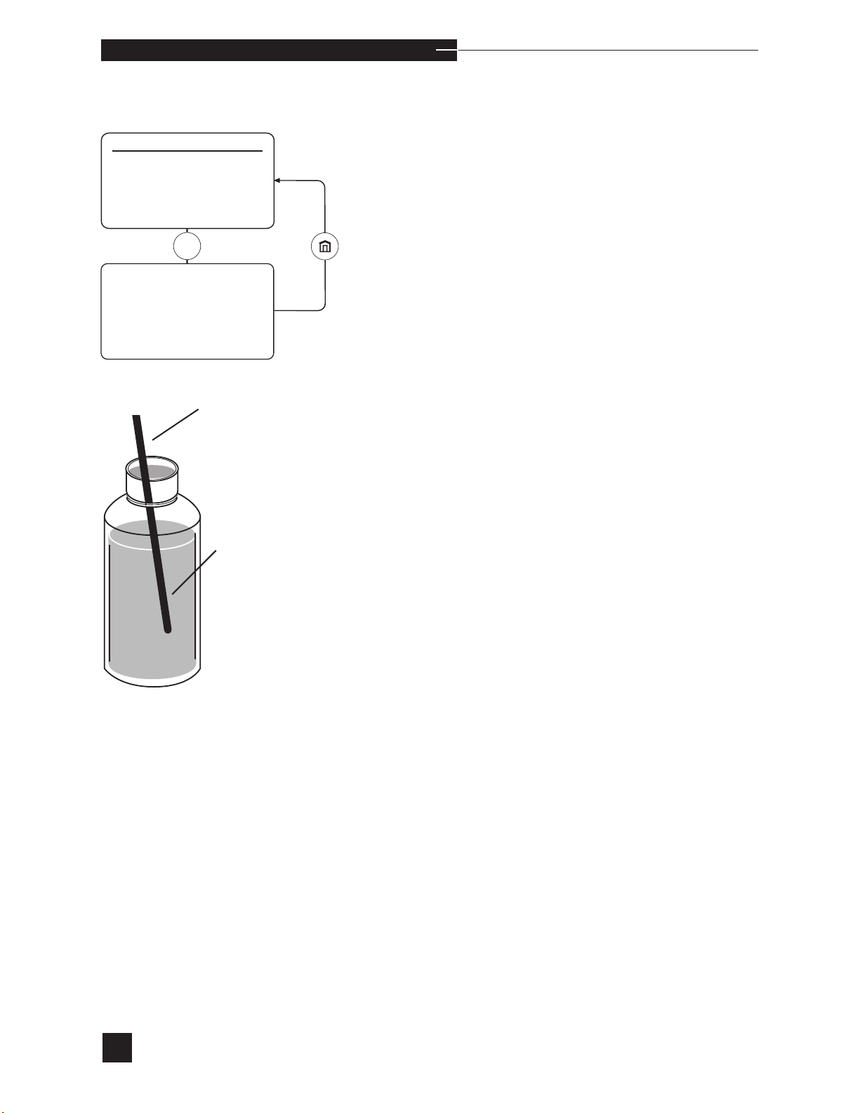
Probe
The fluid path must be cleaned with daily cleaning solution to
remove protein deposits. The analyzer will display CLEANER
REQUIRED if more than 10 samples have been analyzed and
more than 24 hours have elapsed since the last cleaning cycle.
Daily
Cleaner
Select DAILY CLEANER. The display shows LIFT
SAMPLER TO USE CLEANER. The sampler must be in
the syringe mode position. Lift the sampler until PROBE IN
CLEANER? appears. Insert the probe into the cleaning solution
and press YES to aspirate. Hold the container in place until REMOVE
CLEANER RETURN SAMPLER is displayed.
Push the sampler down into the closed position. The cleaning cycle is
followed by an automatic two-point calibration to prepare the analyzer
for sample analysis. LIFT SAMPLER TO ANALYZE pH
PCO2 PO2 Hct Na+ K+ Ca++ is displayed when calibration is successful.
40
sCa
++
is replaced with Cl- when Cl- mode is selected.
Page 47
o p e r a t i n g t h e a n a l y z e r
r
When CLEANER REQUIRED is displayed, a cleaning cycle
must be completed before calibration or sample analysis is permitted.
Performing a cleaning cycle is the only daily maintenance required,
and is essential to promote trouble-free analyzer operation.
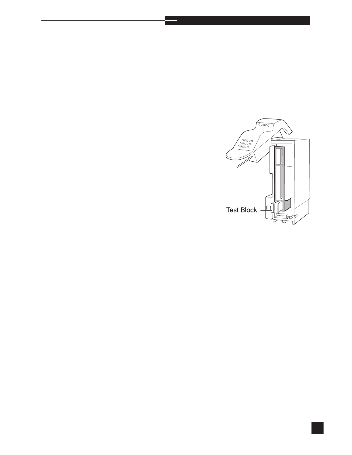
As preventive maintenance or when a PCO
replaced, a more aggressive cleaning procedure can be performed to
remove accumulated protein within the sampler and preheater. The frequency of this procedure is dependent on the number and quality (high
protein concentrations) of patient samples run. This procedure can be
performed infrequently (once every 6 months) or as frequently as once
per month. Each laboratory should establish their own preventative
maintenance program. To perform this preventative maintenance, refer
to the Sample probe/sensor module obstructions procedure found
under FLOW in Troubleshooting.
or PO2 electrode is being
2
H
s
41
Page 48
o p e r a t i n g t h e a n a l y z e r
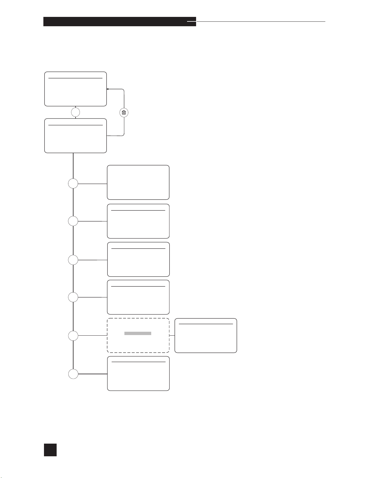
Second Menu
HOME MENU
1 ANALYZE SAMPLE
2 ANALYZE QC
3 CALIBRATE
4 DAILY CLEANER
5 SECOND MENU
5
SECOND MENU
1 STANDBY
2 REPLACE COMPONENTS
3 DIAGNOSTICS
4 STORED INFORMATION
5 SETUP MENU
6 ADJUST DISPLAY
1
2
3
4
5
Default off
6
MANUAL STANDBY
CONFIRM?
REPLACE COMPONENTS
1 REAGENT MODULE
2 ELECTRODES
3 PUMP TUBING
4 SENSOR MODULE/SAMPLER
5 VALVE MODULE
6 SWITCH TO Ca++/Cl
DIAGNOSTICS
1 TEST COMPONENTS
2 TEST FLUIDICS
3 SENSOR STATUS
4 PRIME FLUIDS
5 PRINTOUTS
STORED INFORMATION
1 PATIENT RESULTS
2 QC RESULTS
3 REFERENCE LIMITS
4 CAL/SAMPLE #
5 REAGENT MODULE
6 PRINTOUTS
SECURITY CODE
* * * *
CONFIRM?
ADJUST DISPLAY
1 BRIGHTNESS
2 BRIGHTNESS
3 REVERSE
-
↑
↓
SETUP MENU
1 USER OPTIONS
2 CONFIGURATION
3 PRINTER OPTIONS
4 SET REFERENCE LIMITS
5 PATIENT INFORMATION
6 DELETE DATA
42
Page 49
STANDBY
y
yes
y
o
STANDBY IN 1 MIN
SECOND MEN
U
STANDBY
2 REPLACE COMPONENTS
3 DIAGNOSTICS
4 STORED INFORMATION
5 SETUP MENU
6 ADJUST DISPLAY
MANUAL STANDBY
?
o p e r a t i n g t h e a n a l y z e r
r
Standby
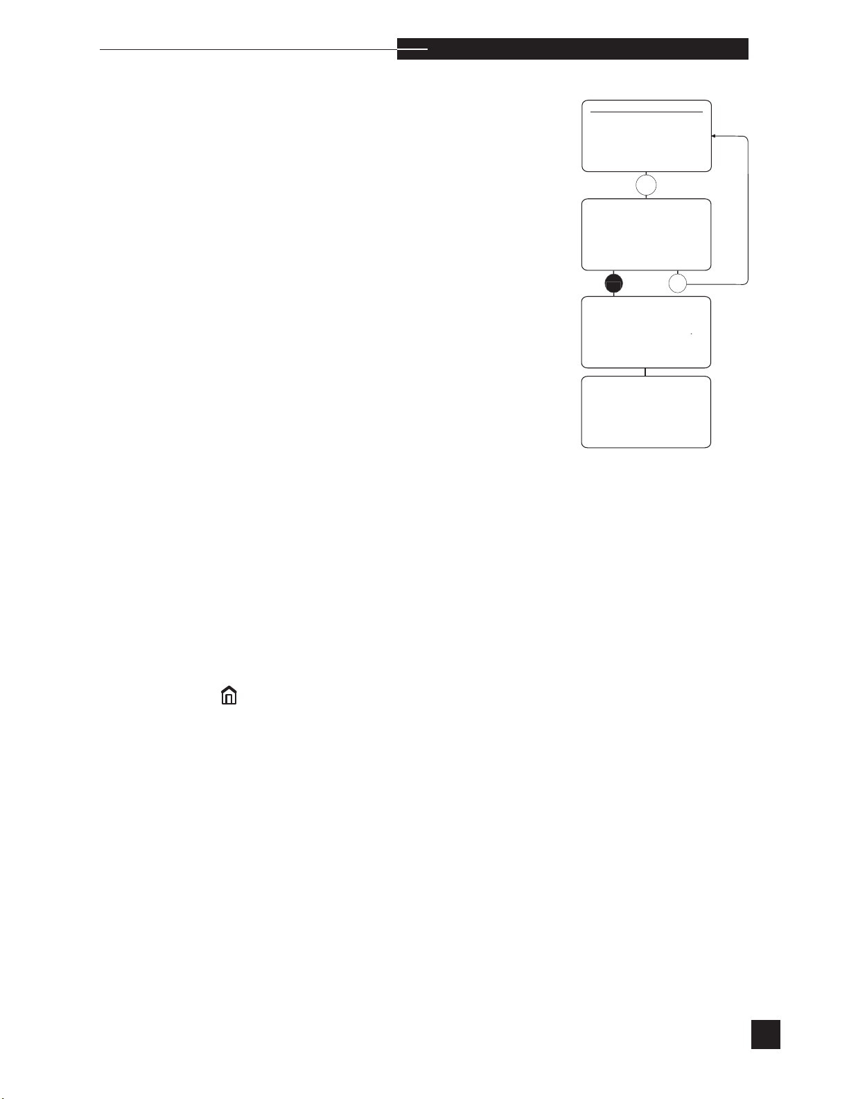
Standby is activated manually or automatically to conserve fluids during long periods of inactivity. When in STANDBY, the analyzer
discontinues automatic calibrations. The sensor module remains at
37.0°C, the valve module remains at 39.0°C, and fluid maintenance
is performed.
Manual Activation
Select STANDBY from the SECOND MENU. The display reads
MANUAL STANDBY CONFIRM?. Press YES to CONFIRM?.
The display will read STANDBY IN 1 MIN. If NO is pressed,
Standby is cancelled.
Automatic Activation
Turn AUTO STANDBY ON under CONFIGURATION in the
SETUP MENU. The analyzer will enter STANDBY at the next
scheduled calibration if no patient or quality control samples have
been analyzed since the last calibration.
During Standby, the display reads STANDBY or STANDBY NOT
CALIBRATED. When STANDBY NOT CALIBRATED
is displayed, a calibration is required before sample analysis, after
deactivating Standby. When STANDBY is displayed, the analyzer
remains calibrated and sample analyses can be performed after
deactivating Standby.
CONFIRM
n
s
Deactivation
From the STANDBY or STANDBY NOT CALIBRATED display, press NO or
to deactivate Standby. Press NO to continue Standby. Once Standby
is deactivated, the HOME MENU is displayed. If ANALYZE
SAMPLE is displayed in the HOME MENU, sample analysis can
be performed. If ANALYZE SAMPLE is not displayed, a calibration is required before sample analysis.
. STANDBY OFF? is displayed. Press YES
43
Page 50
o p e r a t i n g t h e a n a l y z e r
Replace Components
SECOND MENU
1 STANDBY
2 REPLACE COMPONENTS
3 DIAGNOSTICS
4 STORED INFORMATION
5 SETUP MENU
6 ADJUST DISPLAY
2
REPLACE COMPONENTS
1 REAGENT MODULE
2 ELECTRODES
3 PUMP TUBING
4 SENSOR MODULE/SAMPLER
5 VALVE MODULE
6 SWITCH TO Ca++/Cl
-
The EasyStat analyzer contains components which require periodic
replacement. These components include the electrodes (pH, PCO
, Na+, K+, Ca
PO
2
replacement schedule below must be followed to properly maintain the
EasyStat analyzer.
s
It is recommended that quality control material be analyzed after
component replacement to verify performance.
++
, Cl-, and Reference) and reagent module. The
,
2
6
Cl- MODE?
yes
no
PATIENT RESULTS
WILL BE LOST
CONFIRM?
yes
no
RESTART THE ANALYZER.
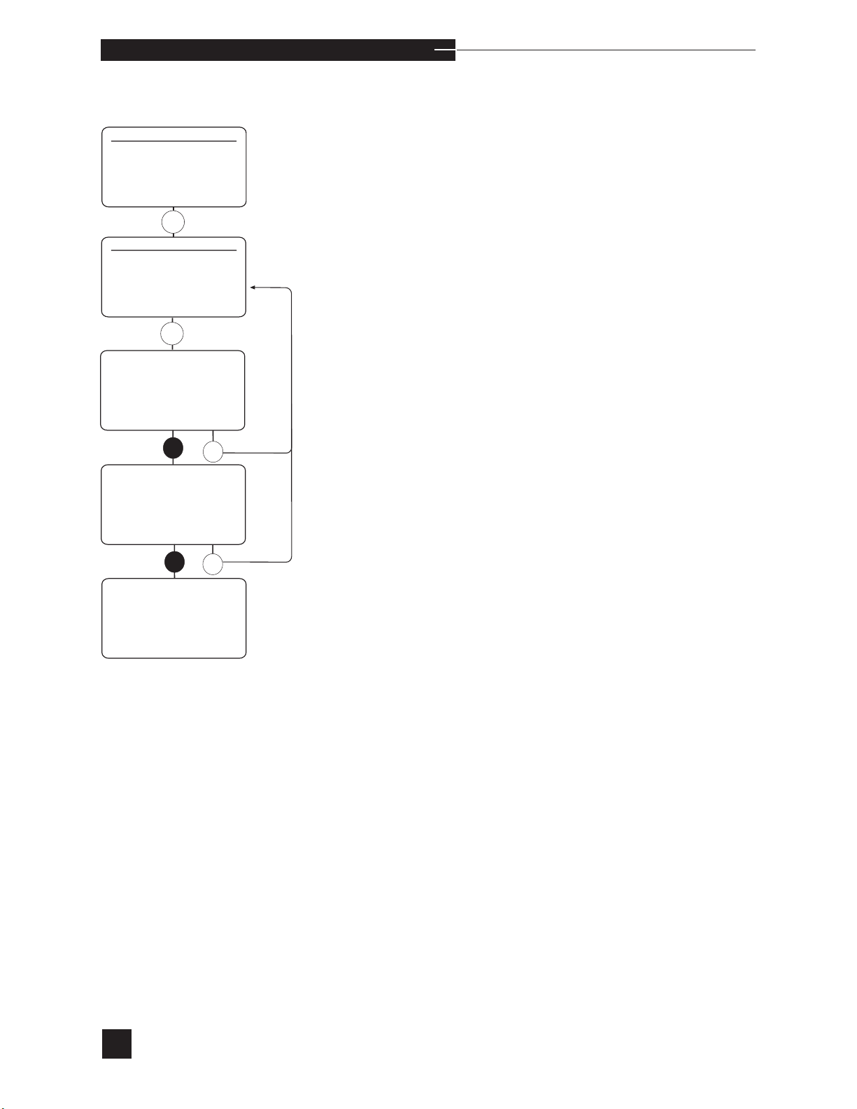
Switch to Ca++/Cl-, select SWITCH TO Ca++/Cl-. The
display will show either Cl- MODE (if the analyzer is currently in
Ca++) or Ca++ MODE (if the analyzer is currently in Cl- mode).
Press YES to move to next screen. Then press YES to confirm. PATI
ENT RESULTS WILL BE LOST. All the stored information
will be erased. The analyzer will restart in the selected mode. Replace
the correct electrode for the selected mode. Follow the instructions in
this chapter to operate the analyzer.
44
Page 51

o p e r a t i n g t h e a n a l y z e r
PUMP TUBING Replace every 6 months
VALVE MODULE Replace as required
SENSOR MODULE Replace as required
SAMPLER Replace as required
pH ELECTRODE Replace as required
r
PCO
PO
ELECTRODE Replace as required
2
ELECTRODE Replace as required
2
Na+ ELECTRODE Replace as required
K+ ELECTRODE Replace as required
Ca++ ELECTRODE Replace as required
Cl- ELECTRODE Replace as required
REFERENCE ELECTRODE Replace every 6 months
REAGENT MODULE Replace when empty or expired
PRINTER PAPER Replace as required
PROBE WIPER Replace every 3 months
s
45
Page 52

o p e r a t i n g t h e a n a l y z e r
To replace EasyStat components, first select REPLACE
COMPONENTS from the SECOND MENU, then proceed with
component replacement as described in this section. If any replacement procedure exceeds 20 minutes, the analyzer beeps and NEED
MORE TIME? is displayed. Press YES to return to the previous
screen. When all replacements are complete, press the
to return to the HOME MENU.
After any component replacement procedure, the WARMING UP
message may appear for up to 30 minutes. During this time, the
EasyStat will not calibrate or analyze samples.
Failure to select the proper component from the REPLACE
H
COMPONENTS menu could result in multiple reliability issues,
including flow problems and/or slope, noise or drift errors.
HOME key
46
Page 53
o p e r a t i n g t h e a n a l y z e r
Reagent Module
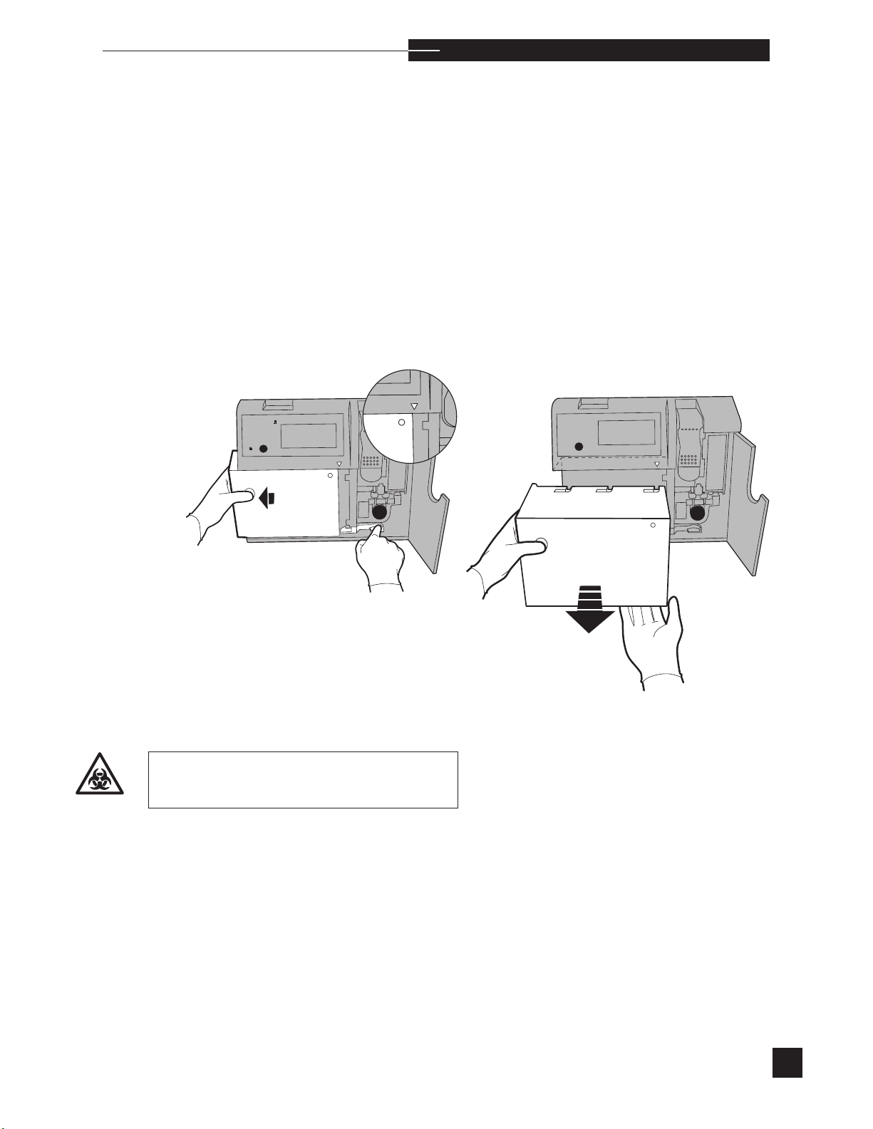
If the EasyStat displays RGNT MODULE EMPTY or RGNT
MODULE EXPIRED, it is necessary to install a new reagent
module. Select REAGENT MODULE from the REPLACE
COMPONENTS menu. Fluid is automatically purged from the
sample path. The display prompts you to REMOVE REAGENT
MODULE. Open the access door. Push in the reagent module release
lever while holding the reagent module on the left side. Pull the module to the left. When the guide arrow points to the edge of the reagent
module, pull the module straight out from the front of the analyzer.
9
7
8
564
231
0
no
yes
r
9
8
7
564
120
no
yes
Used reagent module contains
biohazardous waste.
47
Page 54
o p e r a t i n g t h e a n a l y z e r
Prior to installation, a reagent module must be stored at room temper-
H
ature for a minimum of four hours. When the center of the indicator on
the back of the reagent module becomes dark, the module has been
exposed to excessive temperature and must not be used.
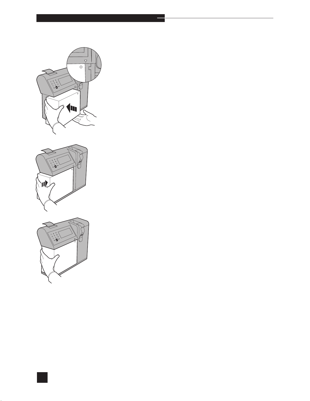
Place the new reagent module into the front of the analyzer. The
guide arrow must point to the right side of the reagent module.
Push the module straight back, then firmly to the right to lock it into
place against the valve module. Press YES to REPLACEMENT
COMPLETED?. The reagents are automatically primed from the
reagent module. When priming is complete, the display indicates the
detection of each fluid with PASS, then automatically returns to the
REPLACE COMPONENTS screen.
The reagent module contains encoded information which is read by
the analyzer upon installation of the reagent module. This information
includes: reagent pH, PCO
ues, and install by date of the reagent module.
, PO2, Hct, Na+, K+, Ca++, and Cl- val-
2
Electrodes
The best indicator that an electrode (pH, PCO2, PO2, Na+, K+,
Ca++, Cl- or reference) requires replacement is when the EasyStat
displays SLOPE ↑/↓ , mV OUT OF RANGE or DRIFT for
a single electrode. These messages generally indicate that the electrode is not functioning correctly. For detailed information, refer to the
Troubleshooting chapter of this manual.
To remove or replace an electrode, select ELECTRODES from
the REPLACE COMPONENTS menu. Fluid is automatically
purged from the sample flow path. When the purge cycle is complete,
REPLACEMENT COMPLETED? is displayed. Proceed with
electrode replacement.
Failure to select the proper component from the REPLACE
COMPONENTS menu could result in multiple reliability issues,
including flow problems and/or slope, noise or drift errors.
48
Page 55
o p e r a t i n g t h e a n a l y z e r
r
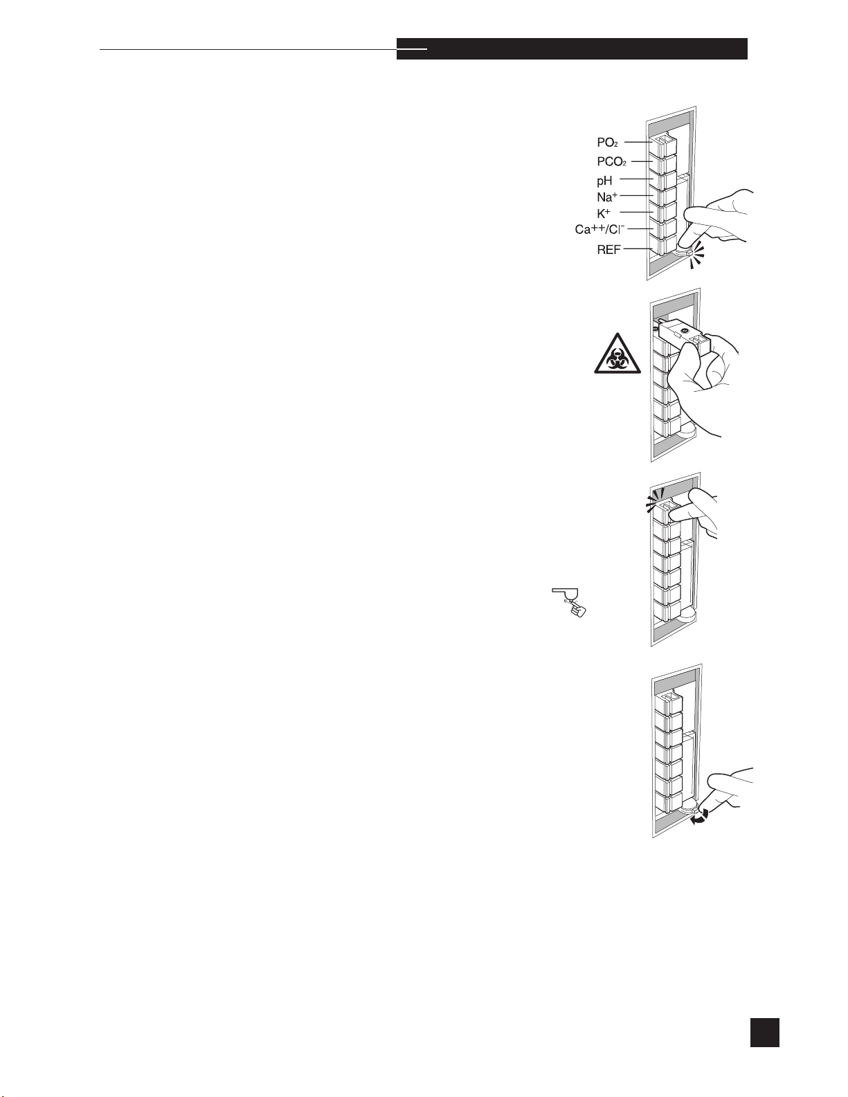
To remove an electrode, push the compression plate down until
latch locks into the open position.
Grip the desired electrode handle, squeeze, and pull it straight out
from the sensor module.
To install a new electrode, push the electrode into its designated
position. The handle snaps into the sensor module. Each electrode
is keyed to assure correct placement. DO NOT FORCE. Refer to the
illustration and the access door label for correct electrode order and
location.
the
Release the compression plate to compress the electrodes within the
sensor module.
Press YES to REPLACEMENT COMPLETED?. Reagents are automatically primed from the reagent module. When priming is complete,
the display indicates the detection of each fluid with PASS, then automatically returns to the REPLACE COMPONENTS screen.
A WARMING UP message may appear for up to 30 minutes. During
this time, the EasyStat will not calibrate or analyze samples.
New electrodes require a short stabilization period to prevent drift
errors. This stabilization is minimized by the analyzer, which performs
calibrations every hour for 8 hours. After this stabilization period,
the analyzer will calibrate at the calibration frequency selected under
CAL FREQUENCY in the CONFIGURATION section of the
SETUP MENU.
s
s
49
Page 56
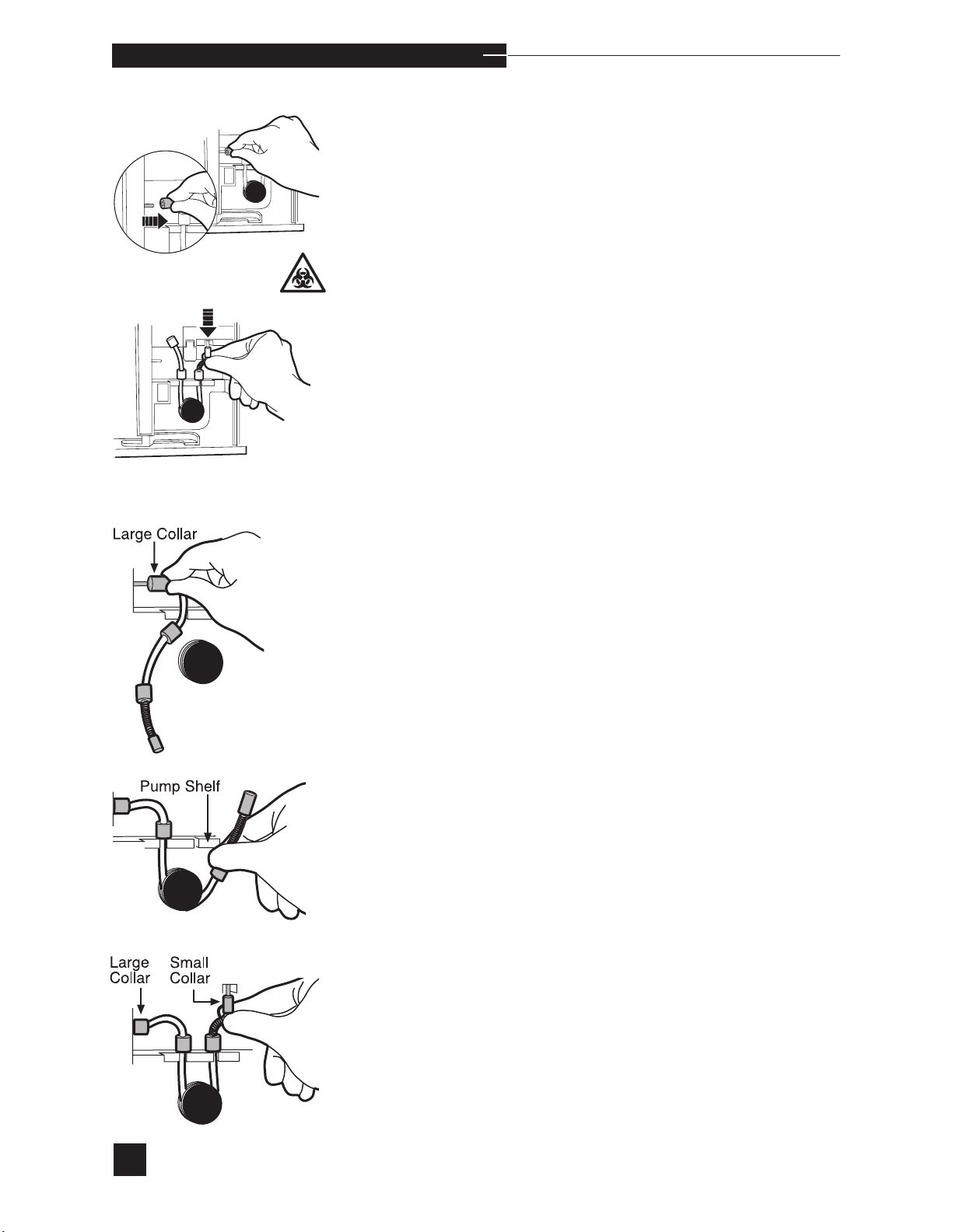
o p e r a t i n g t h e a n a l y z e r
Pump Tubing
Replace the pump tubing every six months, or earlier if the pump
tubing appears worn or flattened. Select PUMP TUBING. Fluid
is automatically purged from the sample flow path. When the purge
cycle is complete, proceed with pump tubing replacement.
s
Remove the pump tubing.
Install the new pump tubing.
Push the two middle collars completely into the back of the slots on the
pump shelf.
Press YES to REPLACEMENT COMPLETED? Reagents are
automatically primed from the reagent module. When priming is complete, the display indicates the detection of each fluid with PASS,
then automatically returns to the REPLACE COMPONENTS
screen.
50
Page 57
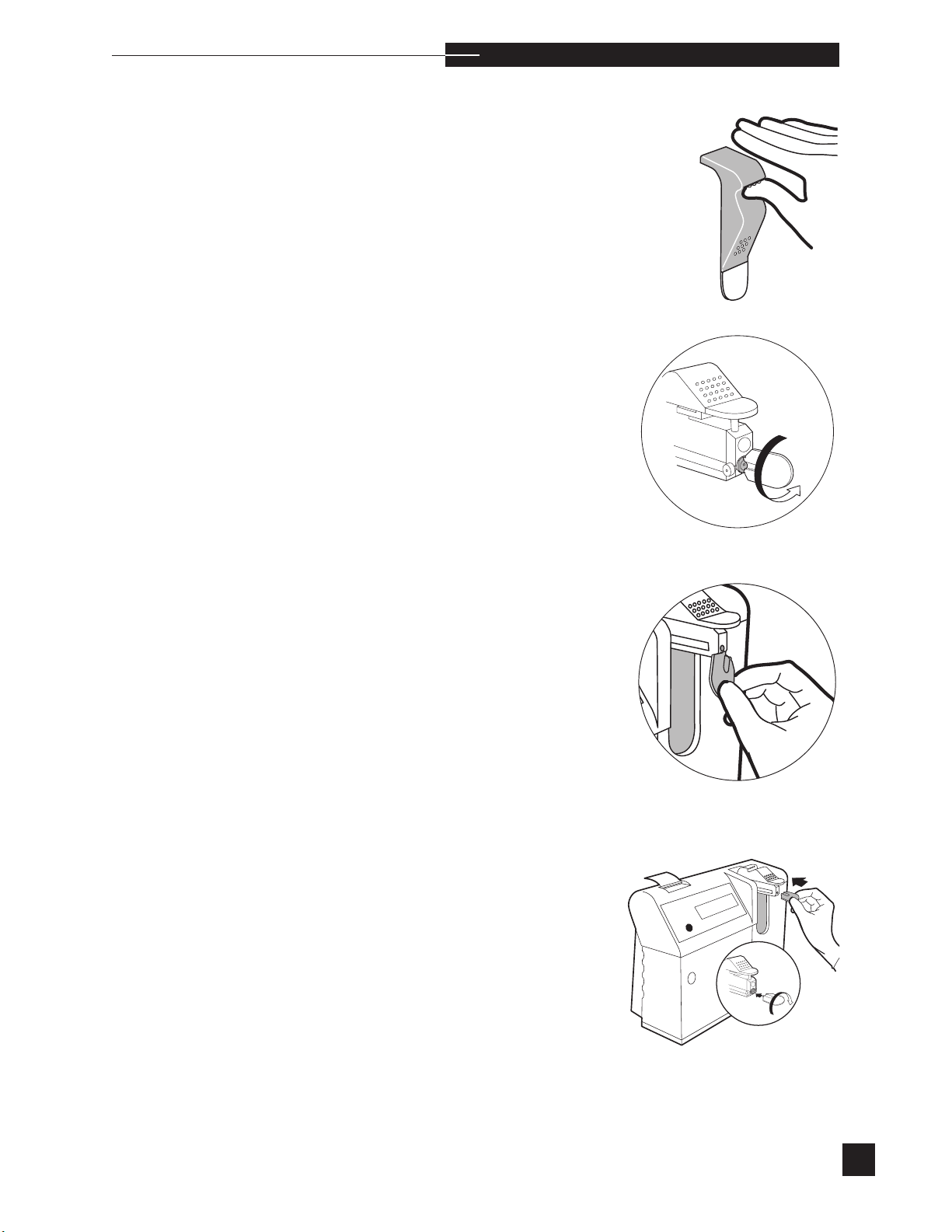
o p e r a t i n g t h e a n a l y z e r
Probe Wiper Replacement
Probe wipers should be changed every 3 months. In some cases they
may last longer, as the frequency of probe wiper replacement depends
on the number and type of samples analyzed. If the motion of the sampler becomes difficult, wipe the probe with an oil wipe (provided in the
probe wiper replacement kit). If the sampler’s motion continues to be difficult, the probe wiper may need replacement.
Raise the sampler to the capillary sample position.
Using the tool supplied in the probe wiper replacement kit, turn the
probe wiper 90° to unlock. This will align the notches on the probe
wiper with the notch on the sampler.
r
Use the tool to pry the used probe wiper from the sampler.
Push the sampler down into the closed position, then raise the sampler
to the sample container mode. Wipe the probe with an oil wipe (provided in the probe wiper replacement kit).
Insert the new probe wiper with the notches aligned. With the tool, turn
the probe wiper 90° into the locked position. Lower and raise the probe
into the sample container mode several times to verify proper probe
motion.
9
8
7
6
5
4
3
2
1
no
yes
0
51
Page 58
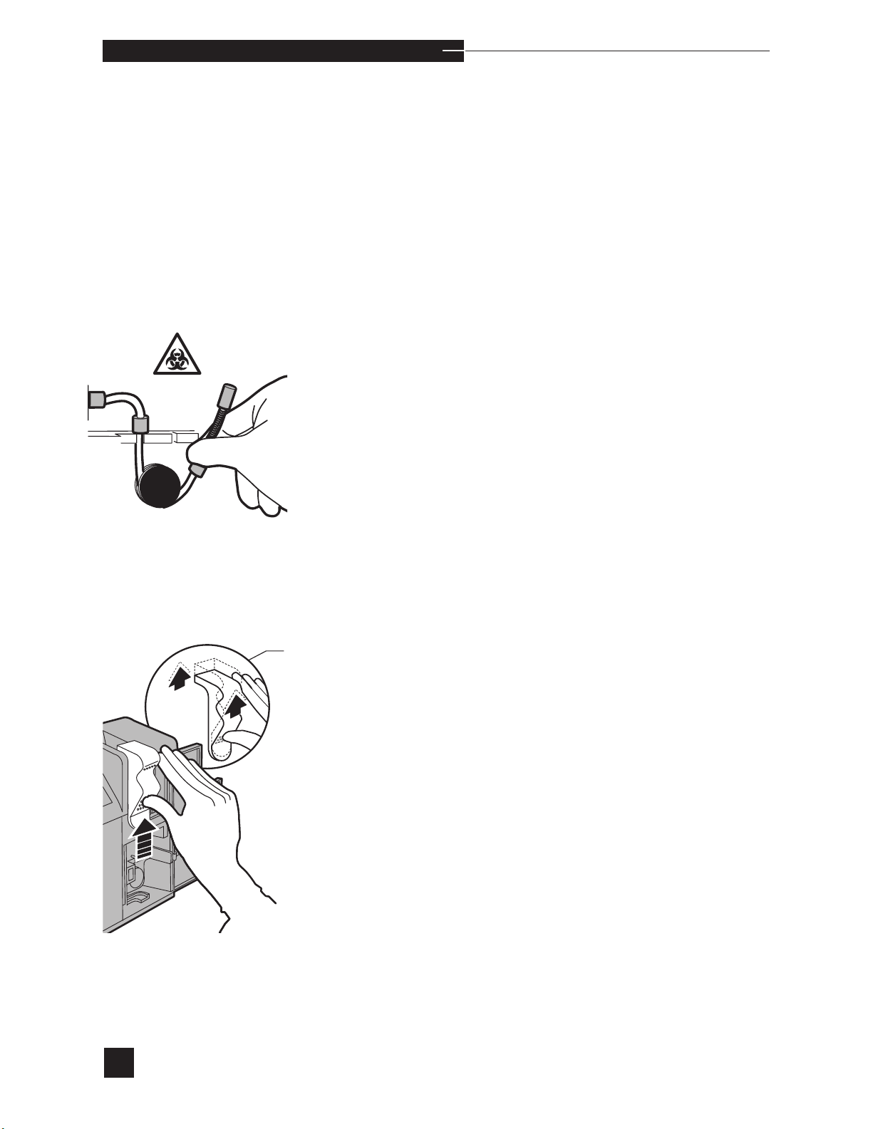
o p e r a t i n g t h e a n a l y z e r
Sensor Module/Sampler
Sensor module or sampler replacement should be infrequent. Sensor
Module replacement will be necessary only if certain display messages become chronic (refer to SENSOR MODULE in Troubleshooting).
Sampler replacement is necessary if the sample probe is bent, damaged or obstructed (refer to FLOW in Troubleshooting), or if the sampler movement is defective.
Select SENSOR MODULE/SAMPLER. Fluid is automatically
purged from the sample flow path. When the purge cycle is complete,
proceed with sensor module and/or sampler replacement.
To remove the sensor module from the analyzer, first remove the pump
tubing.
Disengage the sampler by slightly lifting the sampler until it unlocks
from the valve module.
lightly Lift
ampler
52
Page 59
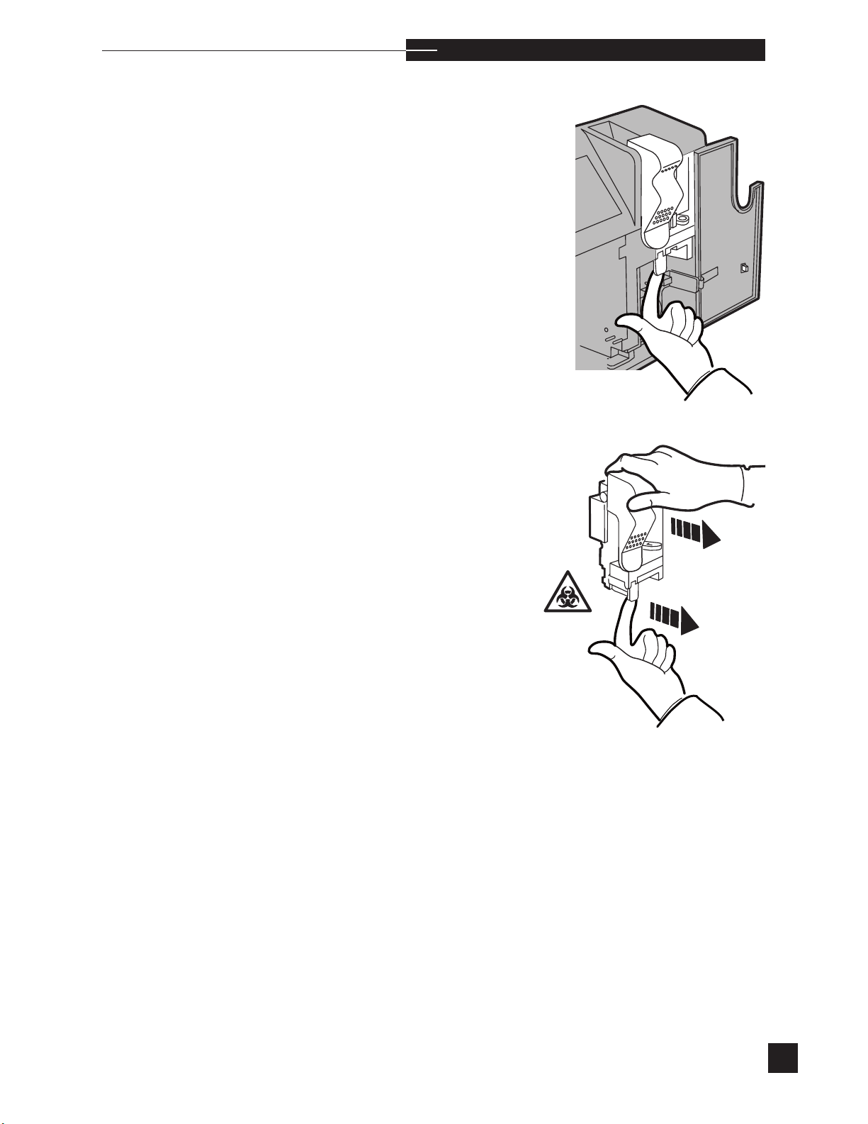
o p e r a t i n g t h e a n a l y z e r
Pull the release lever and the sensor module is disengaged.
Remove from the analyzer.
r
53
Page 60
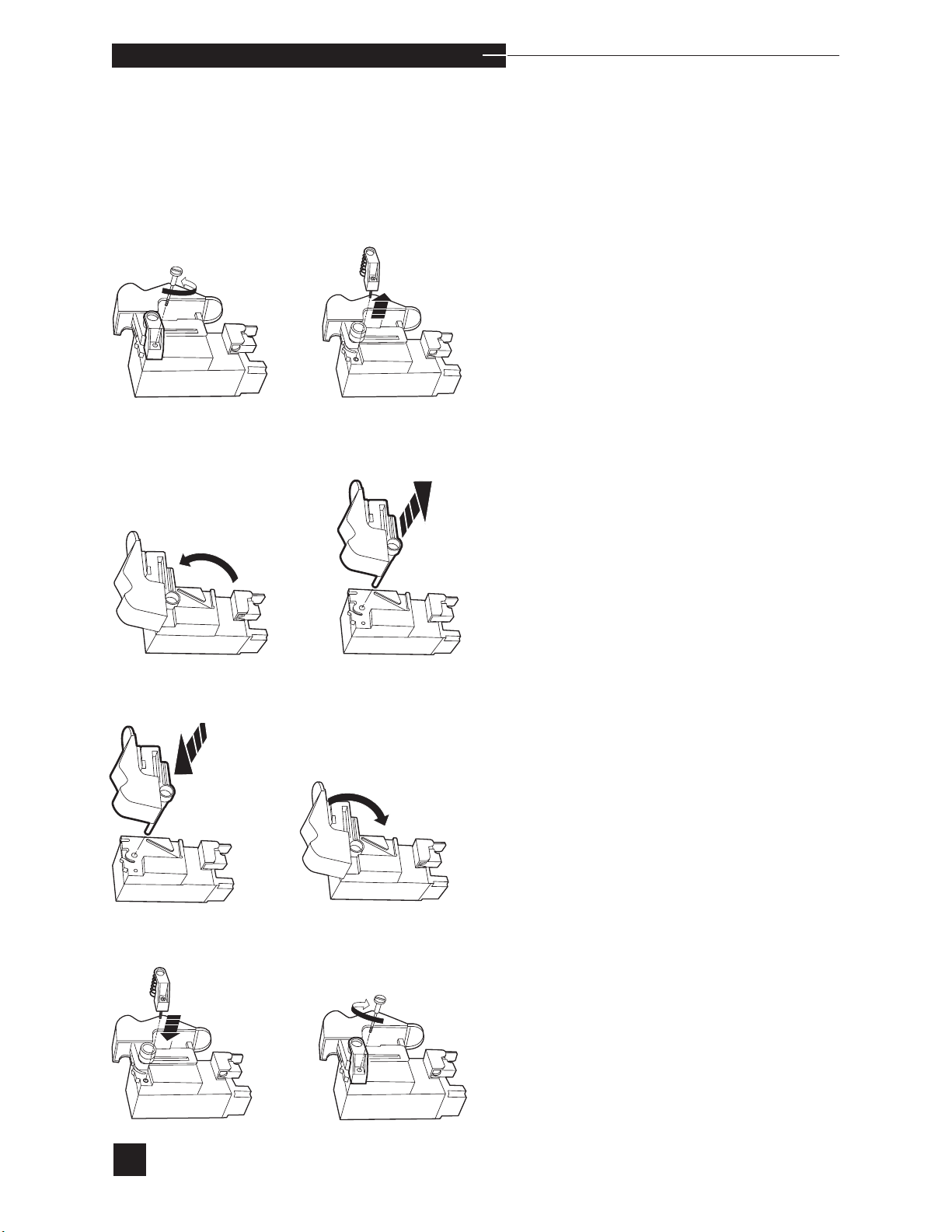
o p e r a t i n g t h e a n a l y z e r
Sampler Removal
To remove the sampler from the sensor module, place the sensor
module on its side with the sampler side up. Using a coin or fingers,
remove the retaining screw from the sensor module. Remove the screw
mount (includes spring).
Rotate the sampler into the capillary mode position, then pull it out of
the sensor module.
Installation
Install the new sampler (includes sample probe and wiper) in the sensor module. Insert the sampler alignment pin into the sensor module.
Rotate the sampler into the closed position.
Install the screw mount (includes spring) into the sampler. Replace the
retaining screw and tighten. DO NOT over tighten.
54
Page 61
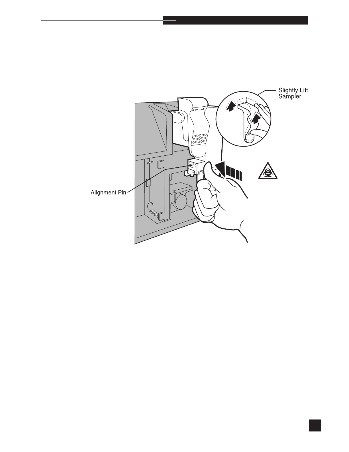
o p e r a t i n g t h e a n a l y z e r
After installing a new sampler, reinstall the complete sensor module.
Lift the sampler up slightly. Place the sensor module on the alignment
pin and, using your thumb, push it straight back into position.
r
55
Page 62
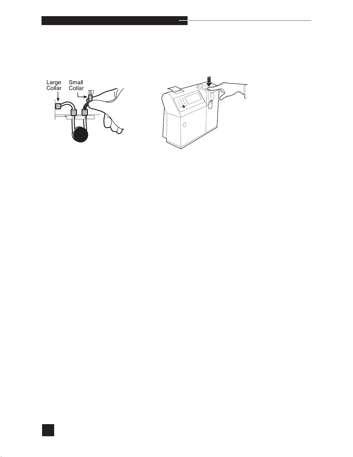
o p e r a t i n g t h e a n a l y z e r
Reconnect the pump tubing to the valve module and sensor module.
Push the sampler down into the closed position.
Press YES to REPLACEMENT COMPLETED?. Reagents
are automatically primed from the reagent module. When priming is complete, the display indicates the detection of each
fluid with PASS, then automatically returns to the REPLACE
COMPONENTS screen.
s
A WARMING UP message may appear for up to 30 minutes.
During this time, the EasyStat will not calibrate or analyze samples.
If the sampler was replaced, the sampler switches may be checked for
proper function. Select the SAMPLER SWITCHES test outlined
under Diagnostics in Operating the Analyzer.
56
Page 63
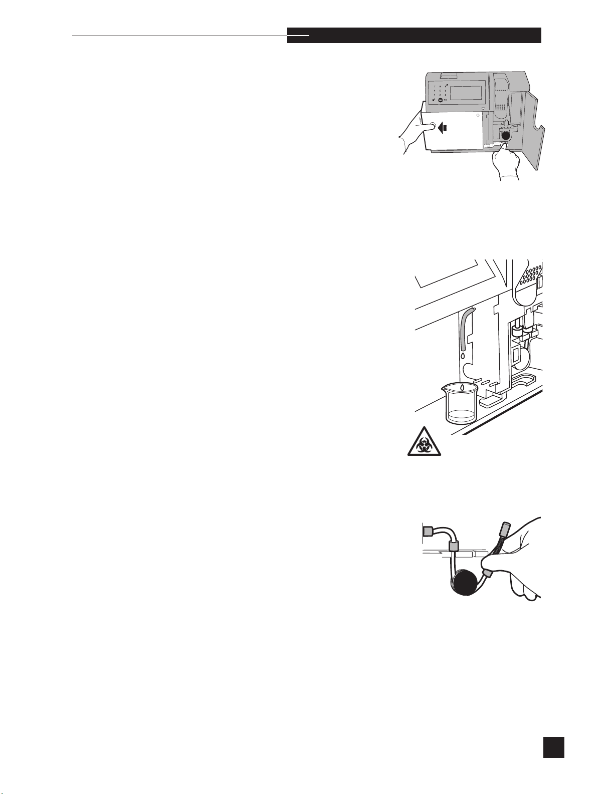
o p e r a t i n g t h e a n a l y z e r
Valve Module
Valve Module replacement is necessary when VALVE ERROR or
VALVE TEMPERATURE error messages become chronic (refer
to VALVE MODULE in Troubleshooting).
r
To remove or replace the valve module, select VALVE MODULE.
s
Fluid is automatically purged from the sample path. REMOVE
REAGENT MODULE is displayed. Remove the reagent module.
PURGE WITH AIR, READY? is displayed. Connect the tub-
ing from the troubleshooting kit to the valve module waste port with
the open end placed into a waste receptacle. Press YES. Calibrant
A, Calibrant B and Calibrant C are automatically purged from the
valve module. When the purge cycle is complete, REPLACEMENT
COMPLETED? is displayed. Proceed with valve module replacement.
Remove the pump tubing.
57
Page 64
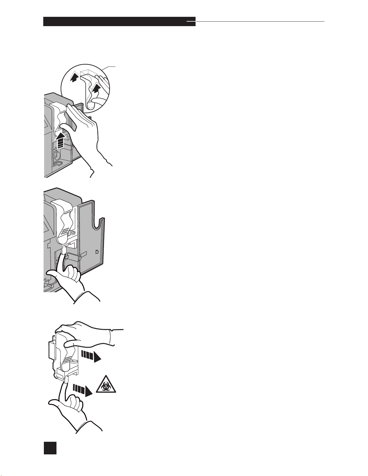
o p e r a t i n g t h e a n a l y z e r
Disengage the sampler by slightly lifting the sampler until it unlocks
from the valve module.
lightly Lift
ampler
Pull the release lever and the sensor module is disengaged.
58
Remove from the analyzer.
Page 65
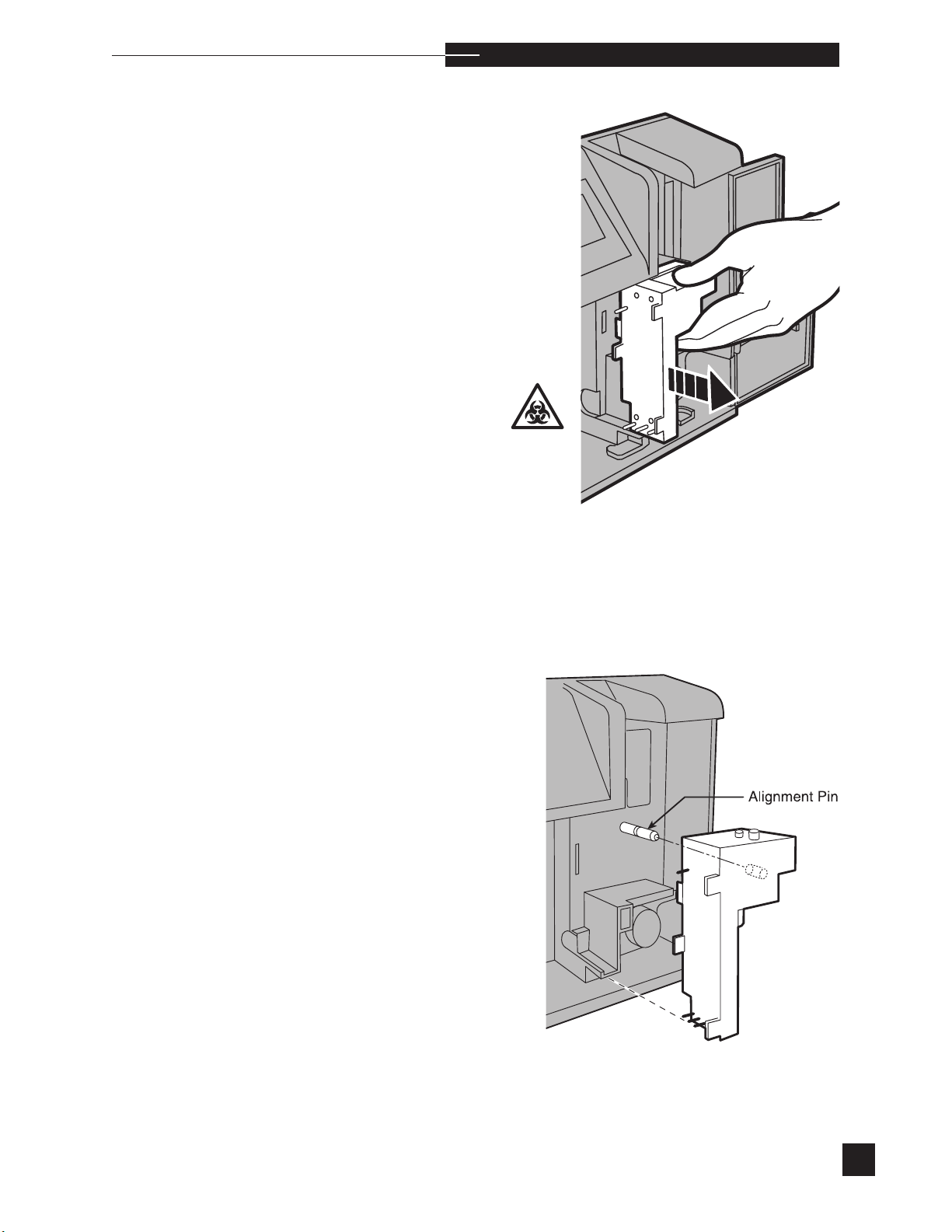
Remove the valve module by pulling it straight out.
o p e r a t i n g t h e a n a l y z e r
r
To install a new valve module, place the valve module onto the alignment pin and push straight back.
59
Page 66
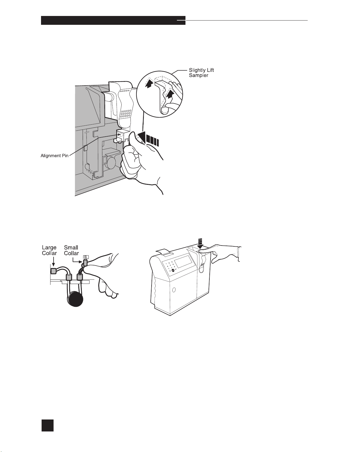
o p e r a t i n g t h e a n a l y z e r
Reinstall the sensor module. Place the sensor module on the alignment
pin and, using your thumb, push it straight back into position.
Reconnect the pump tubing to the valve module and sensor module.
Push the sampler down into the closed position. Close the access door.
Reinstall the reagent module. Press YES to REPLACEMENT
COMPLETED?. Reagents are automatically primed from the
reagent module. When priming is complete, the display indicates the
detection of each fluid with PASS, then automatically returns to the
REPLACE COMPONENTS screen.
s
A WARMING UP message may appear for up to 30 minutes.
During this time, the EasyStat will not calibrate or analyze samples.
60
Page 67
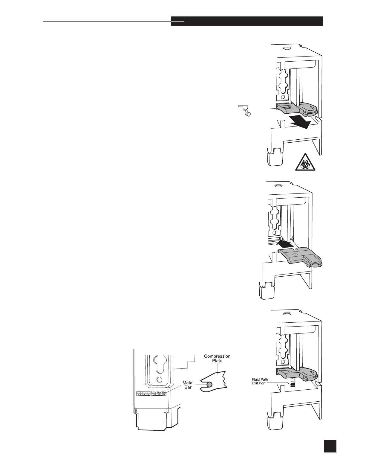
ea
l
o p e r a t i n g t h e a n a l y z e r
Compression Plate
Compression plate replacement is necessary when the latch, spring
mechanism, or seal is damaged. Follow the previous instructions for
electrode or sensor module replacement. To replace the compression
plate, remove all the electrodes. This will ensure that all fluids are
purged from the sample flow path.
Release the compression plate.
Grasp the compression plate and pull it out of the sensor module.
To install the compression plate, insert it into the sensor module. Make
sure that the metal bar at the rear of the module is snapped inside the
hinge tabs. Gently push down on the compression plate to engage
the spring around the fluid path exit port. Reinstall the electrodes as
described earlier in this section.
r
61
Page 68
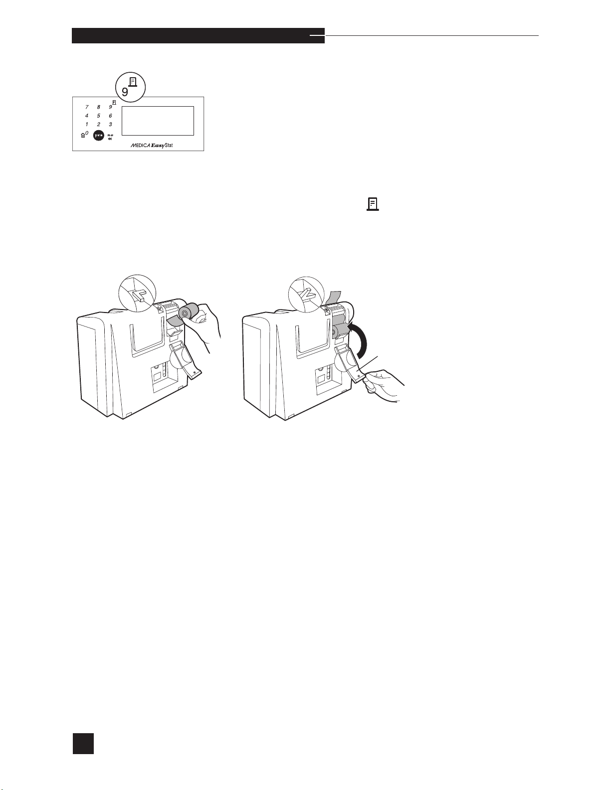
o p e r a t i n g t h e a n a l y z e r
Printer Paper
To install a new paper roll, cut the tape or adhesive off the beginning
of the paper. Open the printer door. Push the paper lever up. Gently
push the edge of the paper into the slot behind the printer. Push the
paper lever down. The paper is automatically fed through the printer.
The paper roll rests in the tray behind the printer. Close the printer
door to protect the paper roll.
s
To advance the paper, press the
Operation of the printer without paper will damage the printer
head. To operate the analyzer for extended periods without paper,
the printer must be turned off. To turn the printer off, refer to
PRINTER OPTIONS in the SETUP MENU.
button.
nter Door
62
s
Operation of the printer without Medica approved printer paper will
result in the premature failure of the printer, voiding the warranty.
Page 69
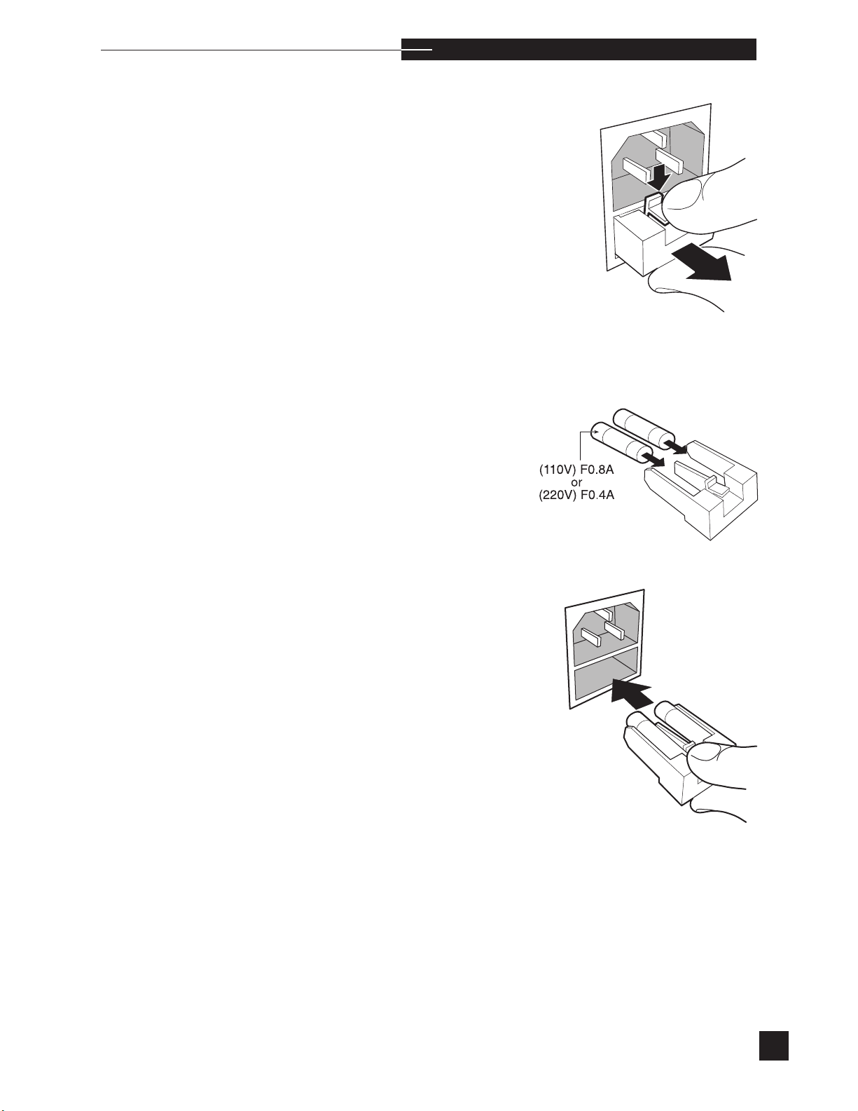
o p e r a t i n g t h e a n a l y z e r
Fuses
The EasyStat analyzer uses 250VAC fuses. When the voltage setting
is 110V, 0.8 amp fuses must be installed. When set to 220V, 0.4 amp
fuses must be installed. Correct fuses must be used with each voltage setting. To replace the fuse(s), remove the power cord, then push
down on the fuse holder release tab and pull straight out.
The EasyStat analyzer will only accept slow blow or time delay fuses.
H
Remove the fuse(s) from the holder and insert the new fuse(s). Confirm
that the fuse rating matches the voltage setting on the analyzer.
r
Reinstall the fuse holder, pushing in until it snaps into place. Connect
the power cord.
Contact your EasyStat dealer when repeated fuse replacement is
required.
s
63
Page 70
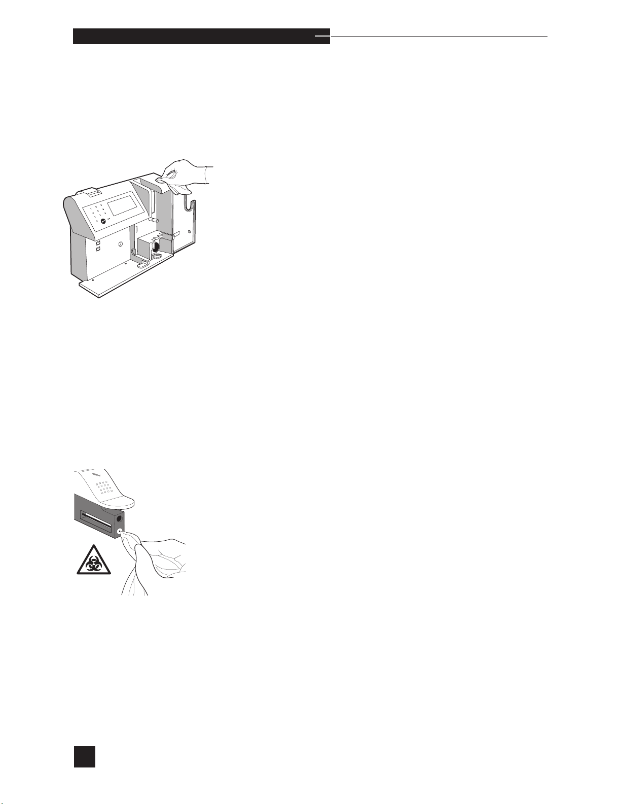
o p e r a t i n g t h e a n a l y z e r
Analyzer Surface Cleaning/Storage/Moving
When complete chassis cleaning or analyzer storage is necessary,
select VALVE MODULE from the
menu. When the purge cycle is complete, remove the reagent module. PURGE WITH AIR, READY? is displayed. Connect the
troubleshooting kit tubing to the valve module waste port with the open
end placed into a waste receptacle. Press YES. Calibrant A, Calibrant
B and Calibrant C are purged from the valve and sensor modules.
Remove the electrodes, sensor module, valve module and pump tube
from the analyzer.
Clean the analyzer with a 10% bleach (0.4-0.6% NaClO) solution.
Apply the solution to a cloth to wipe down all outside surfaces.
REPLACE COMPONENTS
s
H
s
DO NOT use solvents (examples: methyl alcohol, ethyl alcohol, isopropyl alcohol) or cleaning agents containing benzalkonium chloride.
Failureto purge the flow path of air prior to storage could result in
severe damage to the sensor and valve modules.
Clean the sample port of the sampler. Clean all valve module surfaces. DO NOT run bleach solution through the sample path.
Reinstall the valve module and sensor module. The analyzer can now
be stored or moved. The pump tube, reagent module, electrodes, and
power cord should be stored separately.
To resume operation, insert the power cord and install the electrodes,
pump tube and reagent module.
64
s
A WARMING UP message may appear for up to 30 minutes.
During this time, the EasyStat will not calibrate or analyze samples.
Page 71
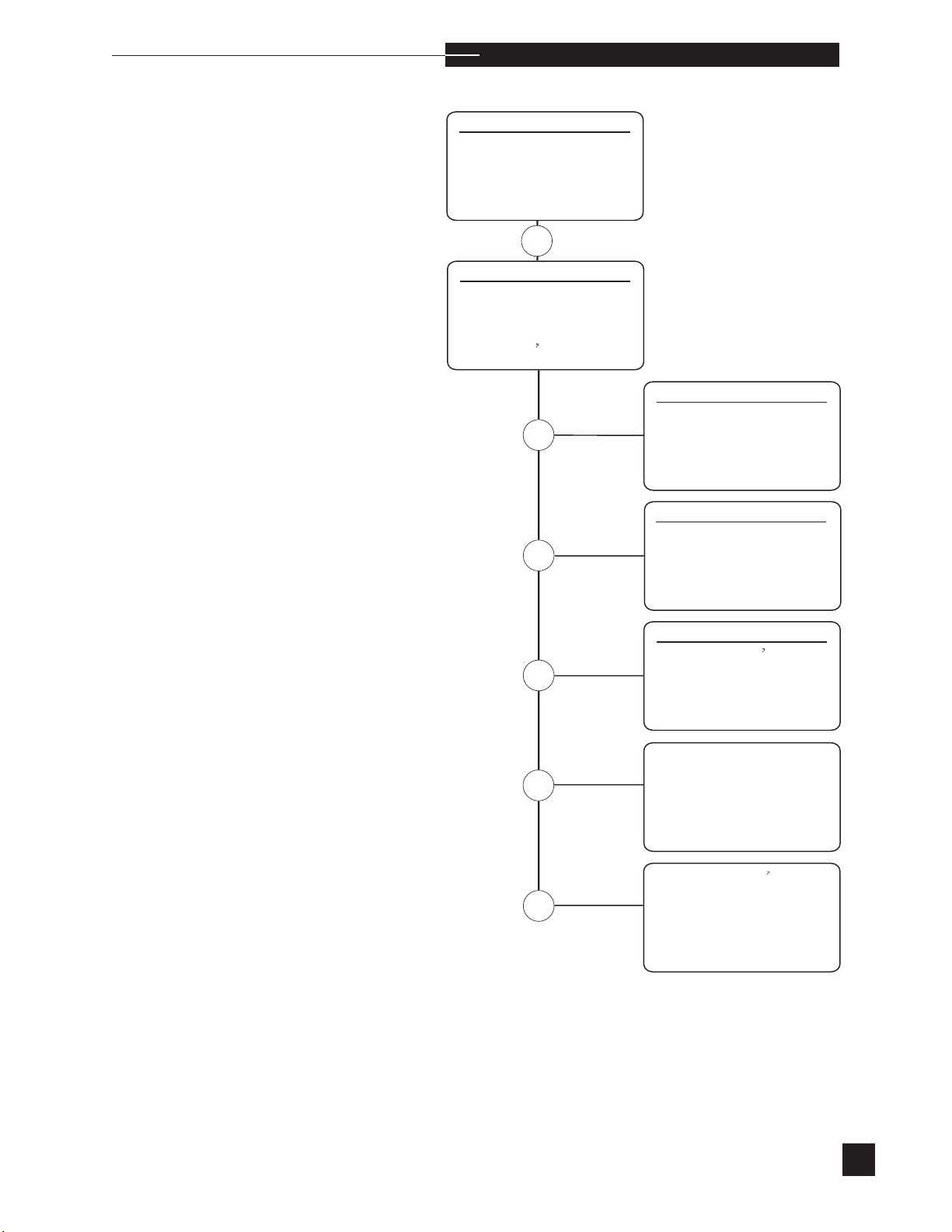
Diagnostics
SECOND MENU
STANDBY
2 REPLACE COMPONENTS
3 DIAGNOSTICS
4 STORED INFORMATION
5 SETUP MENU
6 ADJUST DISPLAY
DIAGNOSTIC
S
TEST COMPONENTS
2 TEST FLUIDICS
3 SENSOR STATUS
4 PRIME FLUIDS
5 PRINT mV
S
TEST COMPONENTS
PUMP
2 VALVE
3 SAMPLER SWITCHES
4 DOOR SWITCH
5 REAGENT READER
TEST FLUIDICS
REAGENT FLOW
2 SAMPLE FLOW
3 BUBBLE DETECTOR CAL
4 PUMP CAL
SENSOR STATUS
ELECTRODE mV
S
2 BAROMETRIC PRESSURE
3 TEMPERATURE
PRIME FLUIDS
PRINT mV
S
o p e r a t i n g t h e a n a l y z e r
r
2
4
5
The tests and data in this section are available to examine the function
and status of individual EasyStat components and fluidics. To identify
component defects or fluidic problems, refer to the Troubleshooting
chapter in this manual.
65
Page 72
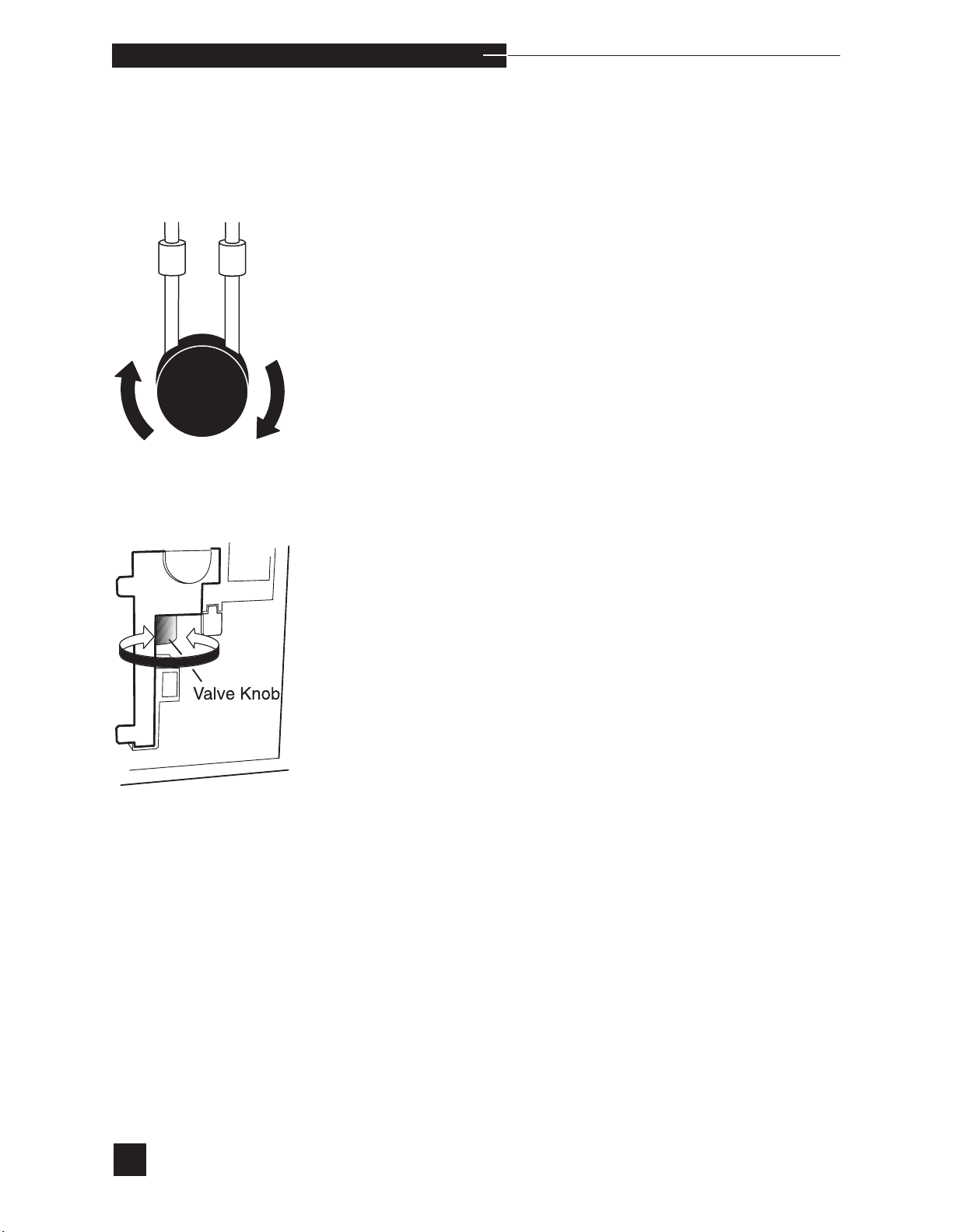
o p e r a t i n g t h e a n a l y z e r
TEST COMPONENTS
Select TEST COMPONENTS to test the operating status of the
pump, valve, sampler switches, door switch and reagent reader.
PUMP
Select PUMP to verify pump function. The screen displays
ROTATING..., then FULL ROTATION?. Look for pump
rotation. When full pump rotation occurs, press YES and PASS is
displayed.
When there is no pump movement or partial pump movement, press
NO and FAIL is displayed. Remove the pump tubing and repeat
the PUMP test. If the test passes, install a new pump tubing, calibrate the analyzer and resume operation. If the test fails, contact
your EasyStat dealer.
VALVE
Select VALVE to verify valve function. The screen displays
ROTATING..., then FULL ROTATION?. Look for rotation
of the valve knob. When full valve knob rotation occurs, press YES
and TESTING... is displayed. Internal testing verifies correct
valve positioning for the Calibrant A, Calibrant B, Rinse, Air and
Home positions. At test completion, PASS or FAIL is displayed.
When there is no valve knob movement or partial valve knob movement, press NO and FAIL is displayed. Repeat the VALVE test. If
the test fails again, the valve may have an obstruction. Refer to VALVE
MODULE in Troubleshooting and follow the instructions for valve module obstructions.
66
Page 73
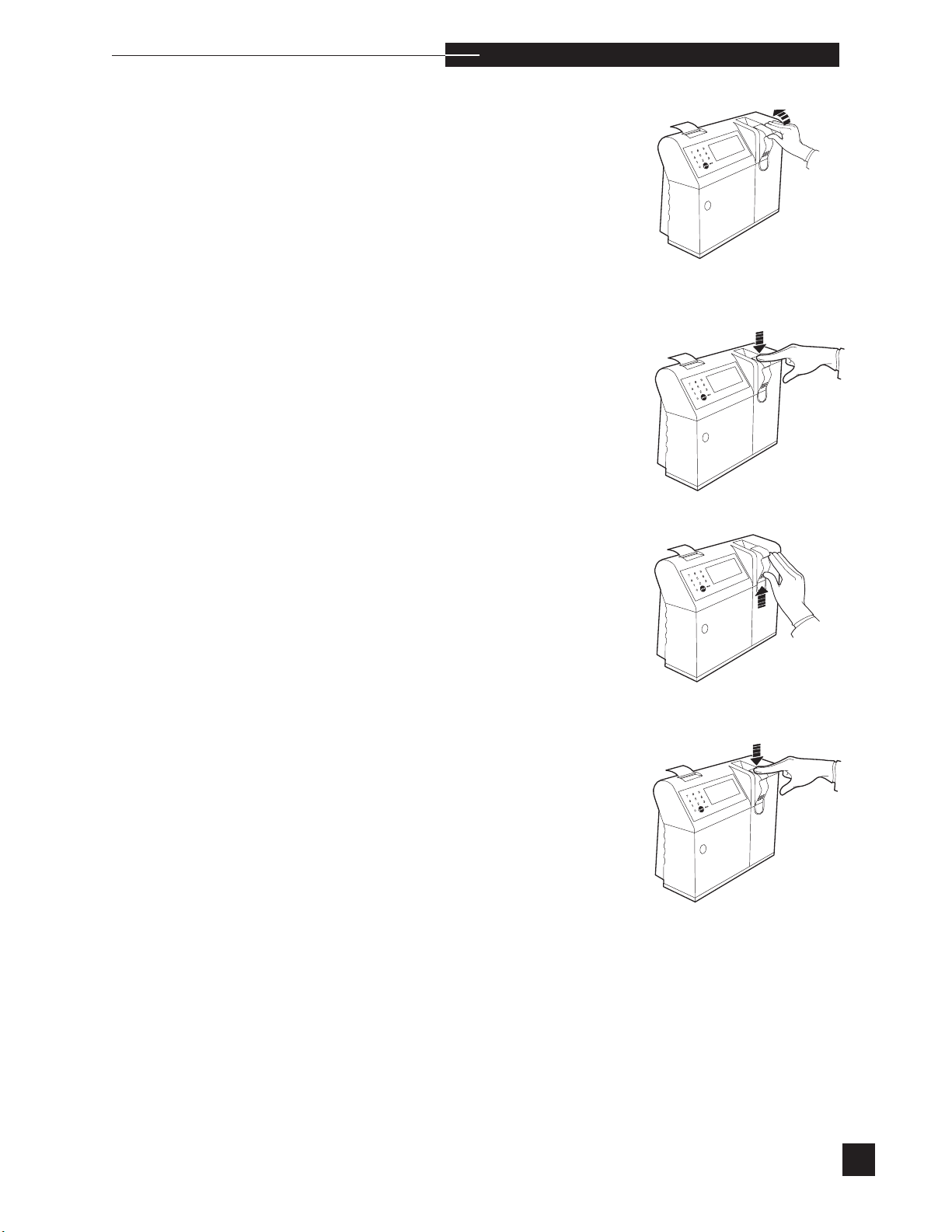
o p e r a t i n g t h e a n a l y z e r
SAMPLER SWITCHES
Select SAMPLER SWITCHES to verify the sampler positioning
sensor and the sample mode switch.
CAPILLARY MODE? is displayed. Lift the sampler to the capillary mode and press YES.
SAMPLER CLOSED? is displayed. Push the sampler down into
the closed position.
r
SYRINGE MODE? is displayed. Lift the sampler to the syringe
mode and press YES.
RETURN SAMPLER is displayed. Push the sampler down
into the closed position. POSITION PASS or FAIL and
MODE PASS or FAIL are displayed. When the SAMPLER
SWITCHES test fails, refer to SENSOR MODULE in Troubleshooting.
67
Page 74
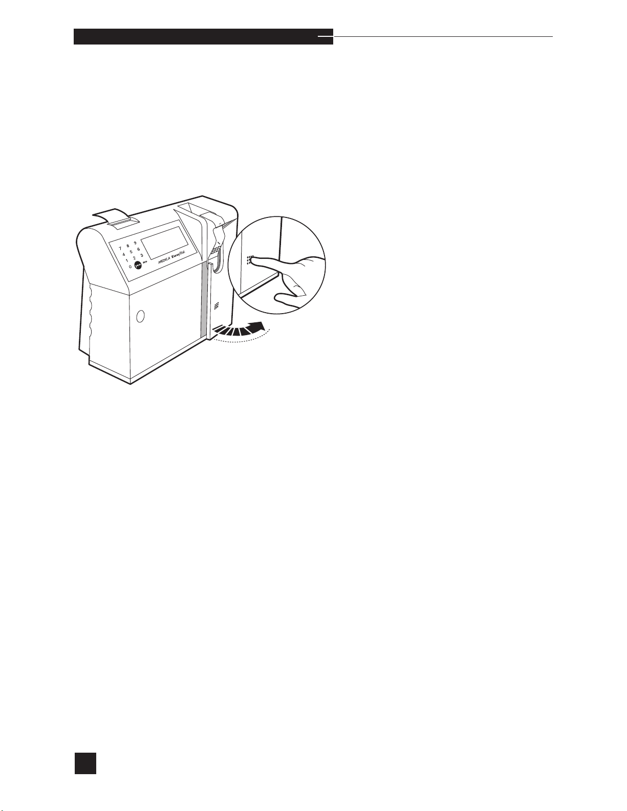
o p e r a t i n g t h e a n a l y z e r
DOOR SWITCH
Select DOOR SWITCH to verify access door switch function. When
DOOR OPEN? is displayed, open the access door and press YES.
When DOOR CLOSED? is displayed, close the access door and
press YES. The screen displays PASS or FAIL. When the test
fails, refer to SENSOR MODULE in Troubleshooting for further instructions.
68
Page 75
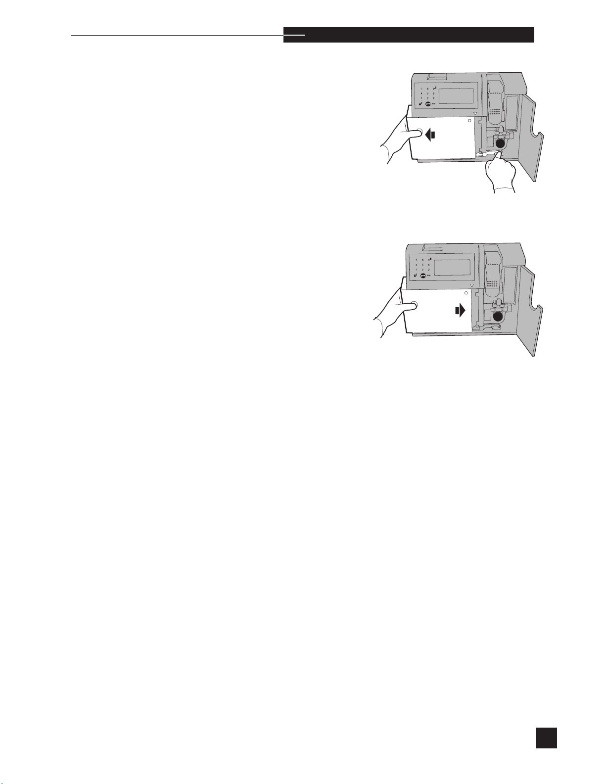
o p e r a t i n g t h e a n a l y z e r
REAGENT READER
Select REAGENT READER to verify reagent reader function.
REAGENT MODULE REMOVED? is displayed. Remove
the reagent module and press YES. REAGENT MODULE
INSTALLED? is displayed. Reinstall the same reagent module
and press YES. PASS or FAIL is displayed.
r
69
Page 76
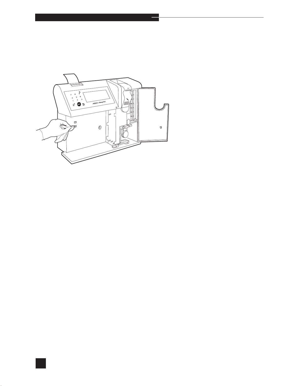
o p e r a t i n g t h e a n a l y z e r
If the above test fails, remove the reagent module and clean the metal
contacts on the analyzer with a damp cloth. Then dry the contacts
thoroughly. Repeat the REAGENT READER test. If it fails again,
contact your EasyStat dealer.
H
Prior to installation, a reagent module must be stored at room temperature for a minimum of four hours.
70
Page 77

Test Fluidics
o p e r a t i n g t h e a n a l y z e r
r
The sampler must be in the closed position for the following tests.
TEST FLUIDICS
Select TEST FLUIDICS to test the operating status of the
reagent flow, sample flow, bubble detector and pump calibration.
REAGENT FLOW
Select REAGENT FLOW to verify the flow of Calibrant
B, Calibrant A, and Calibrant C. When testing is complete,
CALIBRANT B PASS or FAIL, CALIBRANT A
PASS or FAIL and CALIBRANT C PASS or FAIL is
displayed. When the test fails, refer to FLOW in Troubleshooting for
further instructions.
SAMPLE FLOW
Select SAMPLE FLOW to verify the flow of the sample path.
During testing, the screen will display LIFT SAMPLER TO
TEST SAMPLE FLOW. Lift the Sampler in the Syringe Mode
until PROBE IN TEST DYE? is displayed. Place the probe
in the test dye and press YES. Hold the test dye in place, keeping the probe submerged in the test dye until REMOVE TEST
DYE RETURN SAMPLER is displayed. Push the Sampler
down in to the closed position. Testing will automatically occur. When
testing is complete, SAMPLE FLOW PASS or SAMPLE
FLOW FAIL is displayed. When the test fails, refer to FLOW in
Troubleshooting for further instructions.
s
71
Page 78

o p e r a t i n g t h e a n a l y z e r
BUBBLE DETECTOR CAL
Select BUBBLE DETECTOR CAL to verify proper air and fluid
detection. During testing, the screen will display BUBBLE CAL.
When testing is complete, BD PASS or BD FAIL is displayed
with readings for both air and fluid. The difference between the air
and fluid readings must be greater than or equal to 60 for the bubble
detector. In the event of a failure, refer to FLOW in Troubleshooting
for further instructions.
PUMP CAL
Select PUMP CAL to verify proper pump calibration. The pump
calibration counts the number of steps required to move fluid from
the valve module to the bubble detector. The screen displays PUMP
CAL. When testing is complete, PASS or FAIL is displayed
with the number of pumping steps for each test. The number of steps
must be between 460 and 900 for the first value. Refer to FLOW in
Troubleshooting for further instructions.
SENSOR STATUS
Select SENSOR STATUS to view the electrode millivolts, the measured barometric pressure, or the sensor, valve, and room
temperatures.
ELECTRODE mV's
Select ELECTRODE mV’s to view the electrode millivolt readings
for Calibrant A, Calibrant B or Calibrant C.
72
Page 79

o p e r a t i n g t h e a n a l y z e r
BAROMETRIC PRESSURE
Select BAROMETRIC PRESSURE to view the barometric pressure. When the displayed barometric pressure does not match a reference barometer, set the analyzer’s barometric pressure by proceeding to the SETUP MENU and selecting USER OPTIONS,
then BAROMETRIC PRESSURE.
r
Caution: The barometer is calibrated at the factory. The barometric
pressure setting should only be changed to correlate it to a local reference barometer. The proper operation of the analyzer depends on a
correct barometric pressure setting.
TEMPERATURE
Select TEMPERATURE to view the sensor, valve and room temperatures. The readings must be between:
Sensor 36.9° to 37.1°C
Valve 36.0° to 41.0°C
Room 15° to 30°C
If any temperature is not within range, refer to the Troubleshooting
chapter in this manual.
PRIME FLUIDS
Prime the fluid path by pumping Calibrant B, Calibrant A and
Calibrant C from the reagent module.
PRINT mV,S
H
Select PRINT mV,S to display and print millivolt readings for
each parameter. This feature is useful when reporting problems to your
EasyStat distributor.
73
Page 80
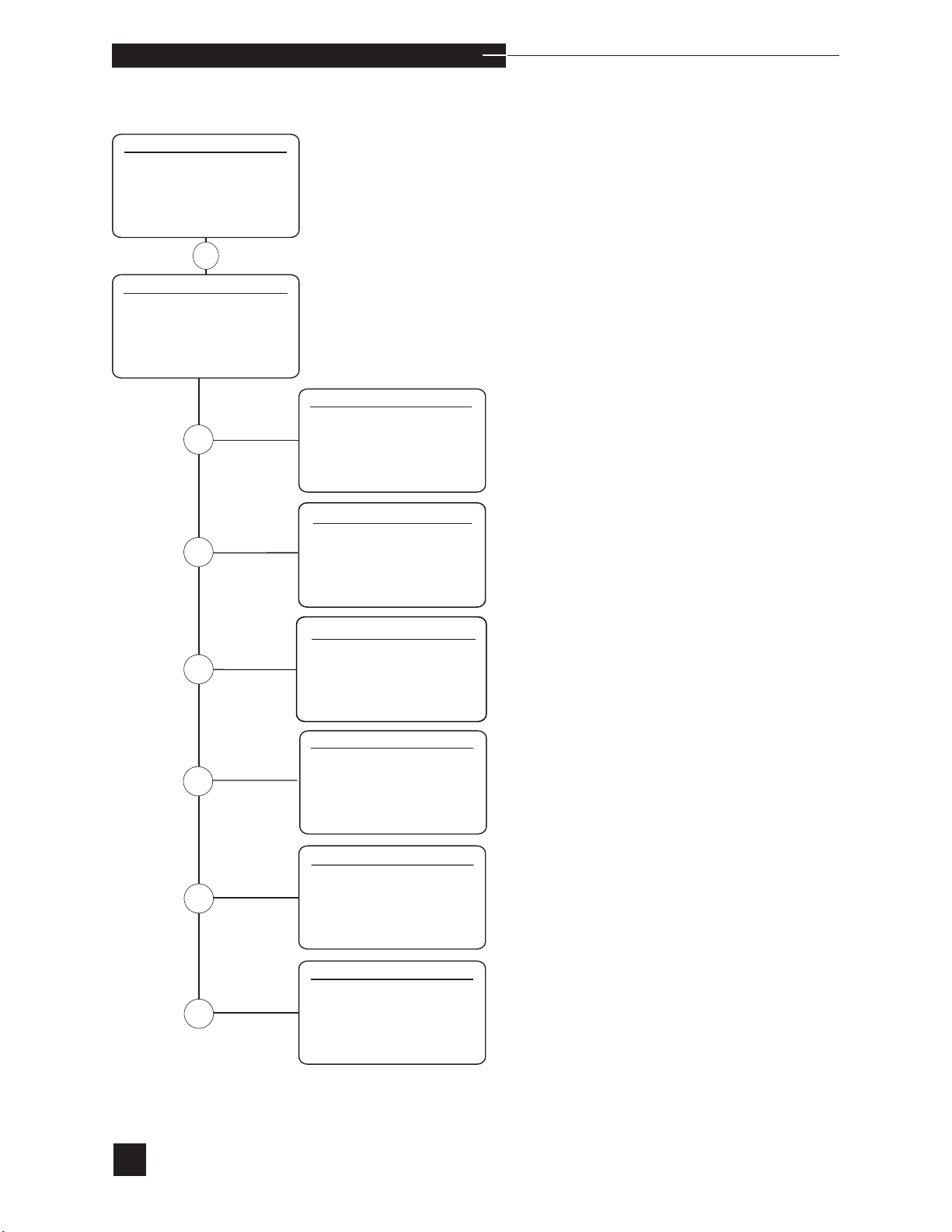
o p e r a t i n g t h e a n a l y z e r
Stored Information
SECOND MENU
1 STANDBY
2 REPLACE COMPONENTS
3 DIAGNOSTICS
4 STORED INFORMATION
5 SETUP MENU
6 ADJUST DISPLAY
4
STORED INFORMATION
1 PATIENT RESULTS
2 QC RESULTS
3 REFERENCE LIMITS
4 CAL/SAMPLE # DATA
5 REAGENT MODULE
6 PRINTOUTS
PATIENT RESULTS
1 LAST
1
2 ALL
3 ENTER ID#
QC RESULTS
1 LAST CONTROL
2
2 PRINT QC STATS
3 PRINT QC RESULTS
4 PLOT QC CHARTS
5 FAILED QC
QC REFERENCE LIMITS
1 LEVEL 1
3
4
5
2 LEVEL 2
3 LEVEL 3
4 Hct LEVELS
CAL/SAMPLE # DATA
1 SLOPES
2 mV’s
3 PUMP/BUBBLE DETECTOR
4 SAMPLE COUNTER
REAGENT MODULE
1 STATUS
2 CONCENTRATIONS
74
PRINTOUTS
1 USER OPTIONS
6
2 CONFIGURATION
3 PRINTER OPTIONS
4 PATIENT LIMITS
5 QC LIMITS
6 PATIENT INFORMATION
Page 81

o p e r a t i n g t h e a n a l y z e r
Select STORED INFORMATION from the SECOND MENU
to obtain stored information on patient and quality control results,
as well as view the reference limits, calibration, and reagent module
information.
PATIENT RESULTS
View or print stored patient results. Up to 64 results are stored.
LAST
View and print the last patient’s measured results.
ALL
Print all patient results.
ENTER ID#
Print the measured results for a specific patient using the keypad or
barcode reader.
r
75
Page 82

o p e r a t i n g t h e a n a l y z e r
QC RESULTS
View the last quality control results, print quality control statistics, and
plot quality control charts.
LAST CONTROL
View the results for the last control samples. Choose from QC Level 1,
QC Level 2, QC Level 3, Hct Level 1 or Hct Level 2.
PRINT QC STATS
Print the statistics for stored quality control data by level.Printing can
be cancelled by pressing NO.
PRINT QC RESULTS
Print the results for stored quality control data by level. Printing can be
cancelled by pressing NO.
PLOT QC CHARTS
Print Levey-Jennings charts using stored quality control statistics. Plot
three quality control levels for each measured parameter or plot all
charts. Printing can be cancelled by pressing NO.
76
Page 83

o p e r a t i n g t h e a n a l y z e r
REFERENCE LIMITS
View the limits for quality control, normal, critical and AMR limits.
QC LEVEL 1,2 or 3, Hct Level 1 or 2
View the current quality control reference limits set for each control
level.
NORMAL
View the analyzer’s normal limits for arterial1, mixed venous3, or
1
venous
samples. The preset limits are:
Arterial Mixed Venous Venous
pH 7.350-7.450 7.340-7.360 7.340-7.360
PCO2 35.0-45.0 mmHg 44.0-46.0 mmHg 44.0-46.0 mmHg
PO2 83-108 mmHg 38-42 mmHg 38-42 mmHg
Hct 35-50% 35-50% 35-50%
Na+ 136.0-146.0 mmol/L 136.0-146.0 mmol/L 136.0-146.0 mmol/L
K+ 3.5-5.1 mmol/L 3.5-5.1 mmol/L 3.5-5.1 mmol/L
Ca++ 1.05-1.32 mmol/L 1.05-1.32 mmol/L 1.05-1.32 mmol/L
Cl- 98.0–106.0 mmol/L 98.0–106.0 mmol/L 98.0–106.0 mmol/L
r
77
Page 84

o p e r a t i n g t h e a n a l y z e r
CRITICAL
View the analyzer’s critical limits for arterial2, mixed venous3, or
2
venous
samples. These limits have been set to be equal to normal
limits. The lab should determine and set their own critical limits which
are consistent with the site of venous sampling and other clinical factors. The preset limits are:
Arterial Mixed Venous Venous
pH <7.300, >7.600 <7.340, >7.360 <7.340, >7.360
PCO2 <20.0, >50.0 mmHg <44.0, >46.0 mmHg <44.0, >46.0 mmHg
PO2 <45, >250 mmHg <38, >42 mmHg <38, >42 mmHg
Hct <25, >70% <25, >70% <25, >70%
Na+ <115.0, >150.0 mmol/L <115.0, >150.0 mmol/L <115.0, >150.0 mmol/L
K+ <3.0, >7.5 mmol/L <3.0, >7.5 mmol/L <3.0, >7.5 mmol/L
Ca++ <0.8, >3.0 mmol/L <0.8, >3.0 mmol/L <0.8, >3.0 mmol/L
Cl- <90.0, >112.0 mmol/L <90.0, >112.0 mmol/L <90.0, >112.0 mmol/L
Proceed to SETUP MENU and select SET REFERENCE
LIMITS to enter new values.
AMR
AMR is available when the feature is turned on in
CONFIGURATIONS. View the analyzer limits for each electrode.
CAL/SAMPLE # DATA
View the slopes and millivolts for each electrode, and the
calibration status for the pump and bubble detectors.
1
Tietz: Fundamentals of Clinical Chemistry, 4th edition, (1996)
2
B. Statland: Clinical Decision Levels for Lab Test, 2nd edition
3
Fink: Clinical Practice in Respiratory Care
78
Page 85

o p e r a t i n g t h e a n a l y z e r
SLOPES
View the slope and calibration status for each electrode (PASS,
FAIL or INVALID). Anelectrode with a PASS status indicates
the last calibration was successful and the electrode is currently calibrated. A FAIL status indicates that an error occurred during the
last calibration. INVALID indicates that the calibration status has
become invalid after the calibration; for example, the reagent module
has expired.
The acceptable slope ranges are:
pH 55.00 - 65.00
PCO
PO
2
2
46.50 - 60.00
1.00 - 5.00
Hct 13.00 - 22.00
Na
+
52.00 - 64.00
K+ 52.00 - 64.00
Ca++ 20.00 - 34.00
Cl- 43.00 - 59.00
r
79
Page 86

o p e r a t i n g t h e a n a l y z e r
mV’s
View the Calibrant A, Calibrant B and Calibrant C mV’s for each
electrode.
PUMP/BUBBLE DETECTOR
View the calibration status and values for the pump, and the calibration status for the bubble detectors, giving the air and fluid readings
for both.
SAMPLE COUNTER
Number of samples that have been performed on analyzer.
REAGENT MODULE
Verify the status and the concentrations of the reagents in the reagent
module.
STATUS
View the current reagent module serial number and installation date;
the EasyStat analyzer serial number on which the reagent module
was first installed; and the reagent volume (%) remaining with the
number of days remaining before calibrants expire.
CONCENTRATIONS
View the calibrant concentration for Calibrant A, Calibrant B, and
Calibrant C for each parameter.
80
Page 87

o p e r a t i n g t h e a n a l y z e r
PRINTOUTS
Print the settings for User Options, Configuration, Patient Limits, QC
Limits, and Patient Information.
USER OPTIONS
Print the User Options settings.
CONFIGURATION
Print the Configuration settings.
PRINTER OPTIONS
Print the Printer Options settings.
r
PATIENT LIMITS
Print the normal and critical patient reference limits.
QC LIMITS
Print the quality control reference limits by level for both controls.
PATIENT INFORMATION
Print the patient information settings.
81
Page 88
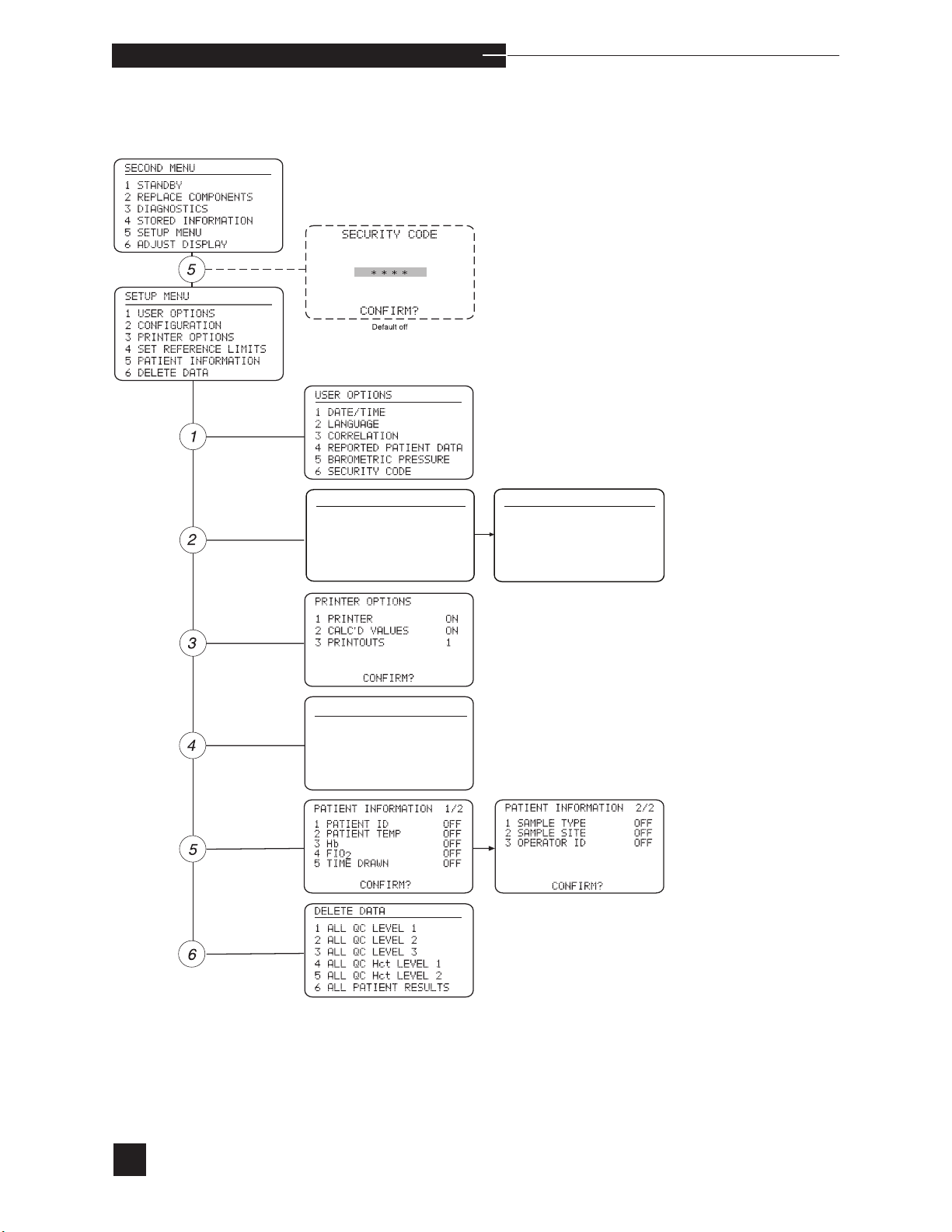
o p e r a t i n g t h e a n a l y z e r
Setup Menu
CONFIGURATION 1/2
1 PO2 / PCO2 / BP mmHg
+ / K+
2 Na
3 Hct %
4 Hb
5 BC CHECKSUM OFF
++
/ Ca
mmol/L
CONFIRM ?
g/dL
REFERENCE LIMITS
1 QC
2 NORMAL
3 CRITICAL
4 AMR
CONFIGURATION 2/2
1 CAL FREQUENCY 8 HRS
2 AUTO STANDBY OFF
3 TEMPERATURE C
4 Rili-BAK OFF
5 AMR OFF
CONFIRM ?
82
sCa
++
is replaced with Cl- when Cl- mode is selected.
Page 89
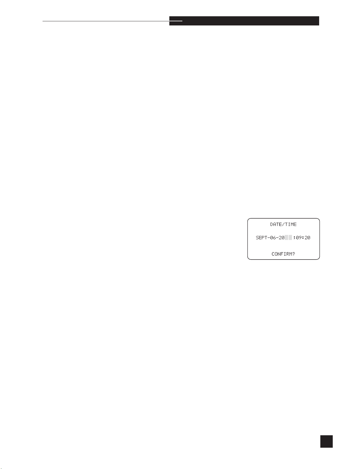
o p e r a t i n g t h e a n a l y z e r
Select SETUP MENU from the SECOND MENU to set the functional parameters of the EasyStat analyzer.
r
Enter the security code if SECURITY CODE is turned ON
under USER OPTIONS. Turning the SECURITY CODE
ON prevents unauthorized personnel from entering and changing the
SETUP MENU.
USER OPTIONS
Set:
DATE/TIME, LANGUAGE, CORRELATION,
REPORTED PATIENT DATA, BAROMETRIC
PRESSURE, SECURITY CODE
Make sure you remove the reagent Module when changing the
DATE/TIME.
DATE/TIME
Set the month, day, year and time (expressed as a 24 hour clock).
Press NO to edit the current date and time. The cursor appears
beneath the month. Each time NO is pressed, the month changes.
When the correct month appears, press YES and the cursor moves
to the day. Enter the correct day by pressing the number keys. Press
YES to proceed to the year and time. Press NO to correct the previous
entry and YES to advance. When all entries are confirmed, the display returns to USER OPTIONS.
ss
s
83
Page 90
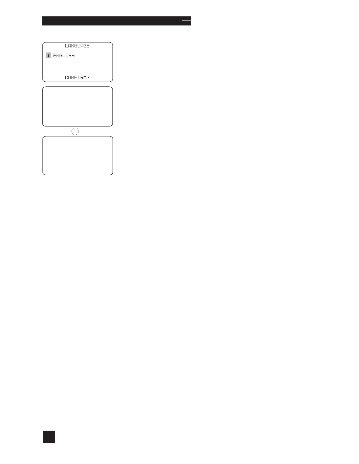
CORRELATION
SET PARAMETERS
2 APPLY CORRELATION
APPLY CORRELATION
PATIENT RESULTS OFF
2 QC RESULTS
OFF
CONFIRM?
o p e r a t i n g t h e a n a l y z e r
LANGUAGE
Select the language by pressing the number keys. Press YES to
CONFIRM?.
CORRELATION
The analyzer can be set to correlate with or match the results of
another analyzer. To correlate the EasyStat analyzer to a reference
analyzer, data must first be collected from samples run on both analyzers. The correlation values can be applied to patient and quality
control results.
First, analyze a minimum of 10 patient samples in each of the low
abnormal, normal, and high abnormal ranges for each of the analytes.
Each patient sample must be run on both analyzers. The EasyStat
correlation equations must be set with the default (1.00x + 0.0) coefficients when analyzing the samples.
Next, determine the correlation factors by performing a regression
analysis of the data. The EasyStat data must be the “x” data, and
the reference analyzer must be the “y” data. The regression slope
is entered as the correlation slope, and the regression intercept is
entered as the intercept.
84
Page 91
o p e r a t i n g t h e a n a l y z e r
r
Next, select CORRELATION, then SET PARAMETERS to
view the stored correlation equations. To change any of these values,
press NO to CONFIRM?, and enter any new correlation slopes
and/or intercepts for each analyte. The cursor highlights the selection.
Press the number keys to set the slope and intercept, and press YES to
confirm the correct individual values. Press NO to change “+” to “-”,
then press YES.
When entries are complete, press YES and CONFIRM? is displayed. To correct mistakes, press NO to return to the top of the list,
and re-enter numbers. Press YES to confirm your entries. The pH,
, PO2, Hct, Na+, K+, Ca++ and Cl- slope input range is 0.90 to
PCO
2
1.10. The acceptable intercept input range for pH is -0.020 to 0.020,
PCO2 is +/-5 mmHg and PO2 is +/-10 mmHg, Na+ is +/-10 mM,
K+ is +/- 0.6 mM, Ca++ is +/- 0.6 mM, Cl- is ± 10 mM, and Hct is
+/- 4%. The default values are: slope =1.00 and intercept = 0.00.
Finally, analyze patient samples on each analyzer to confirm the correlation. Correlation values can be applied to patient and/or quality
control results. Correlation is not applied to normal, critical, or quality
control ranges.
CORRELATION 1/2
SET PARAMETERS
SLOPE INTERCEPT
pH = X.XX X+X.XXXX
= X.XXX+ X.X mmHg
PCO
2
PO
= X.XXX+ X mmHg
2
CONFIRM?
CORRELATION 2/2
SET PARAMETERS
SLOPE INTERCEPT
Hct = X.XXX+ X%
+
= X.XXX+ X.Xmmol/L
Na
+
= X.XXX+ X.XX
K
++
= X.XXX+ X.XXmmol/L
Ca
CONFIRM?
mmol/L
Using correlations does not change the measurement range, only the
displayed range. The following is a detailed example for pH. The
measurement range is 6.500 to 8.000. If the pH correlation is 1.00x
+ 0.020, the display range is: 1.00 (6.500) + 0.020 to 1.00 (8.000)
+ 0.020 or 6.520 to 8.020. Using this example, if a sample had a
measured pH less than 6.500, the result would be reported as
< 6.52↓↓.
s
sCa
++
is replaced with Cl- when Cl- mode is selected.
85
Page 92
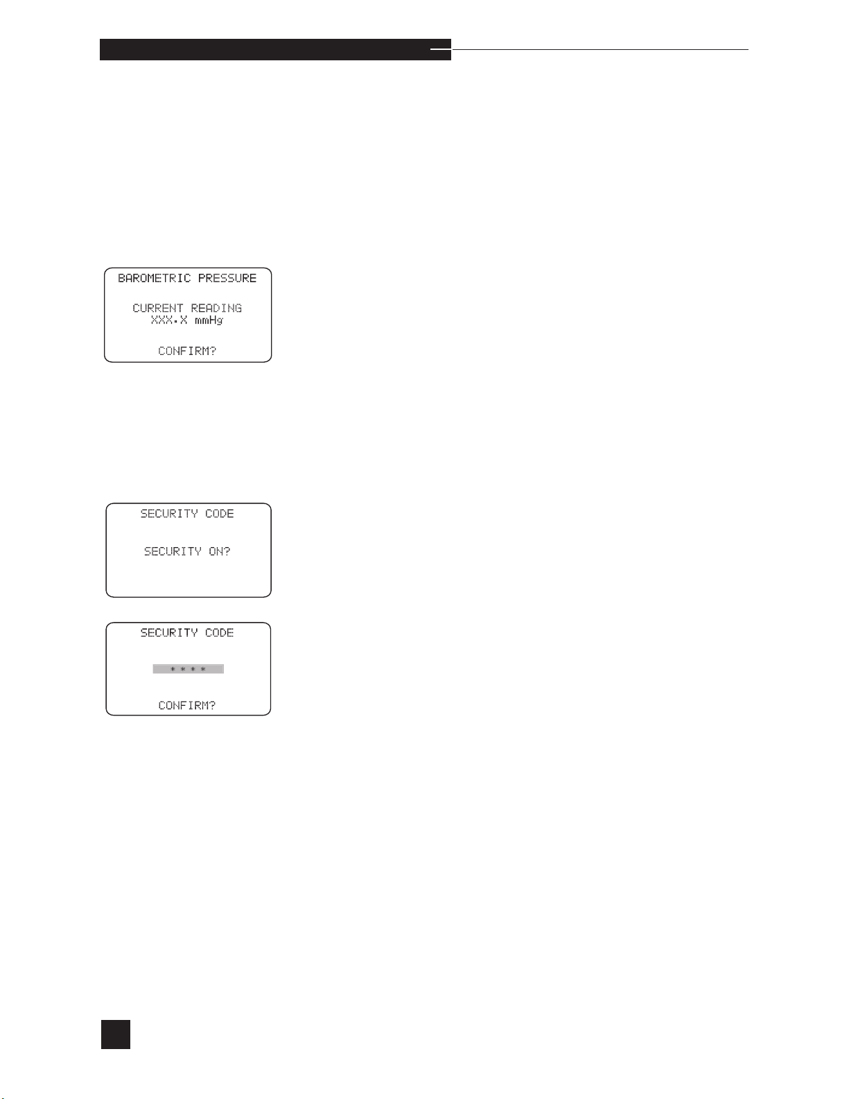
o p e r a t i n g t h e a n a l y z e r
REPORTED PATIENT DATA
Select ANALYTES, then REPORTED DATA to enable or disable the reporting of specific analytes. A calibration is required after
analytes are turned on or off under REPORTED DATA.
Select
CALCULATED VALUES
to enable or disable the
reporting of specific calculated values.
BAROMETRIC PRESSURE
View or set the measured barometric pressure. The barometric pressure is measured using a factory calibrated electronic sensor. When the
displayed barometric pressure matches a reference barometer, press
YES to CONFIRM?. When it does not match a reference barometer,
press NO. Press the number keys to enter the actual barometric pressure. Press YES when the entry is complete. If the barometric pressure
does not change, verify the accuracy of the reference barometer. When
the error remains, contact your EasyStat dealer.
SECURITY CODE
To activate this feature, press YES when SECURITY ON? is displayed.
Enter up to a four digit code and press YES to CONFIRM?. The
SETUP MENU is displayed. The security code will be required in
the future for access to the SETUP MENU.
86
To turn the security code off, press YES when SECURITY OFF?
is displayed. Answering NO to SECURITY OFF? will require
entering the security code in the future for access to the SETUP
MENU.
Page 93
o p e r a t i n g t h e a n a l y z e r
r
CONFIGURATION
Select CONFIGURATION to set analyzer options. Select from:
PO2/PCO2/BP, Na+/K+/Ca++, Hct, Hb, CAL
FREQUENCY, AUTO STANDBY, and TEMPERATURE.
PO2/PCO2/BP
Change the measurement units (select mmHg or SI units) for PO2,
PCO2 and barometric pressure. Results for SI units are shown in KPa.
Na+/K+/Ca
++
or Cl
-
Change the measurement units (select mmol/L or mmEq/L units).
HCT
Change the measurement units (select % or V/V) for hematocrit.
Hb
Change the measurement units for Hb. Select mmol/L, g/L or g/dL.
BC Checksum
Turn the feature ON or OFF. When the feature is ON, the analyzer
has the uses the last digit in the barcode to perform a barcode checksum calculation.
CONFIGURATION 1/2
1 PO2 / PCO2 / BP mmHg
2 Na
3 Hct %
4 Hb
5 BC CHECKSUM OFF
CONFIGURATION 2/2
1 CAL FREQUENCY 8 HRS
2 AUTO STANDBY OFF
3 TEMPERATURE C
4 Rili-BAK OFF
5 AMR OFF
+
/ K+ / Ca
++
CONFIRM ?
CONFIRM ?
mmol/L
g/dL
CAL FREQUENCY
Press the number keys to select and change an option. Press YES to
CONFIRM? all configuration settings.
Select the time interval between automatic two-point calibrations.
Select from: 2 hours, 4 hours, 8 hours
sCa
++
is replaced with Cl- when Cl- mode is selected.
87
Page 94

o p e r a t i n g t h e a n a l y z e r
AUTO STANDBY
Select ON or OFF. When ON, the analyzer will enter standby automatically. Standby is available manually with either selection.
TEMPERATURE
Change the temperature unit. Select Fahrenheit (F) or Celsius (C).
RILIBAK
Turn RiliBAK ON or OFF to use the statistic-based method for performing QC analysis required in Germany.
AMR
Turn AMR (Adjustable Measurement Range) ON or OFF. When ON,
the default values are the low and high instrument range for each
parameter. The ranges can be changed to ranges within the default
limits.
PRINTER OPTIONS
Select printing options.
s
PRINTER
Turn the printer ON or OFF. When the analyzer runs out of printer
paper, turn the printer OFF to prevent damage to the mechanism.
CALC’ D VALUES
Turn printing of calculated values ON or OFF.
PRINTOUTS
Select up to four (4) sample printouts.
SET REFERENCE LIMITS
Select SET REFERENCE LIMITS to set the quality control limits
for each level, and the normal and critical patient limits.
It is recommended that any stored quality control results be deleted
prior to entering information for a new lot of quality control. Refer to
DELETE DATA in the SETUP MENU.
88
Page 95
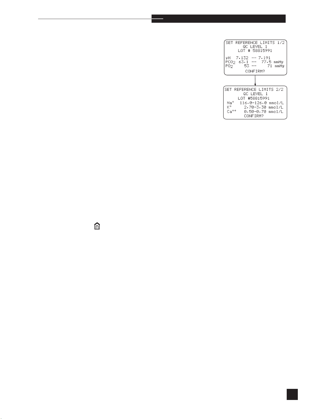
QC LEVEL 1, 2, 3, Hct
o p e r a t i n g t h e a n a l y z e r
r
Enter, by level, quality control lot numbers and set the minimum and
maximum values for each parameter. Press the number keys to set
the values. Press YES to confirm the individual values and move to
the next parameter. When the limits are correct for a particular level,
press YES to confirm and move to the next electrode. When NO is
pressed as a response to CONFIRM?, entries can be corrected.
If RiliBAK is turned ON in CONFIGURATIONS, set the target
and percent deviation for each parameter.
To enter quality control information using the barcode reader, EasyQC
quality controls must be used.
To enter quality control information using the barcode reader, select
QC LEVEL 1, 2, 3, Hct 1 or 2. LOT # is highlighted on the display. Using the barcode reader, scan in the lot number provided on the quality control insert sheet. Next, the parameter
will be highlighted. Scan in the pH range (verify that the displayed
range matches the insert sheet). Repeat for the remaining parameters.
When all entries are complete, press YES to CONFIRM?. When
NO is pressed as a response to CONFIRM?, the settings can be
corrected. Repeat for each level of control. To proceed with quality
control analysis, press
to return to HOME MENU.
ss
s
Use the default limits as a guideline. Each laboratory should establish
their own normal and critical limits. Press the number keys to select
NORMAL or CRITICAL limits.
sCa
++
is replaced with Cl- when Cl- mode is selected.
s
89
Page 96
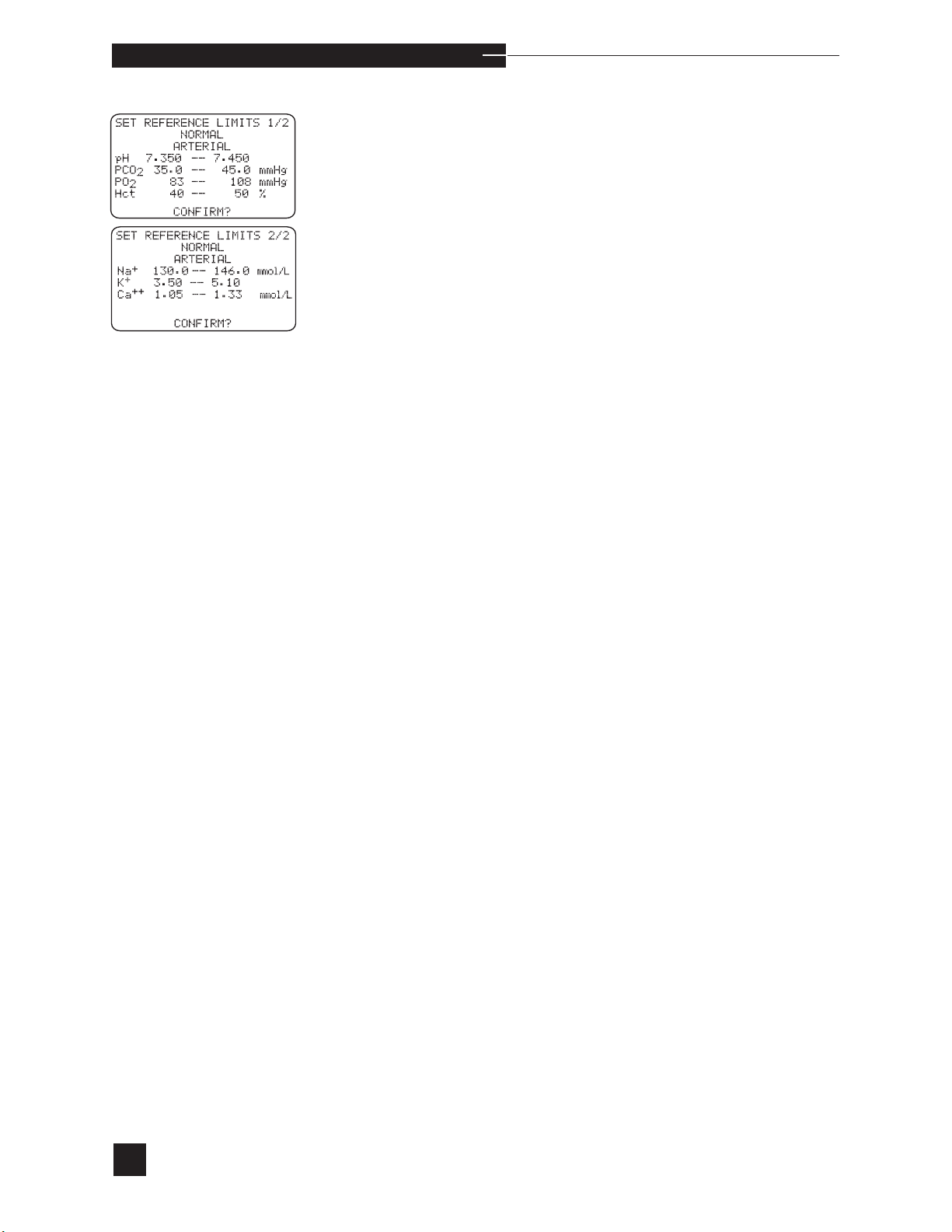
o p e r a t i n g t h e a n a l y z e r
NORMAL
Set the normal range for each parameter. Select arterial, mixed
venous or venous. To change the ranges, press NO to CONFIRM?.
Press the number keys to enter the desired limits, and YES to confirm
each individual setting and advance to the next entry. When all limits
are entered, press YES to CONFIRM? to accept all entries. When
NO is pressed as a response to CONFIRM?, entries can be corrected.
When patient results fall within the normal range for the EasyStat
analyzer, no arrows appear with the measured results. For example,
when the normal pH range is 7.350 - 7.450, no flags are displayed/
printed for patient pH results greater than or equal to 7.350 and less
than or equal to 7.450.
90
sCa
++
is replaced with Cl- when Cl- mode is selected.
Page 97
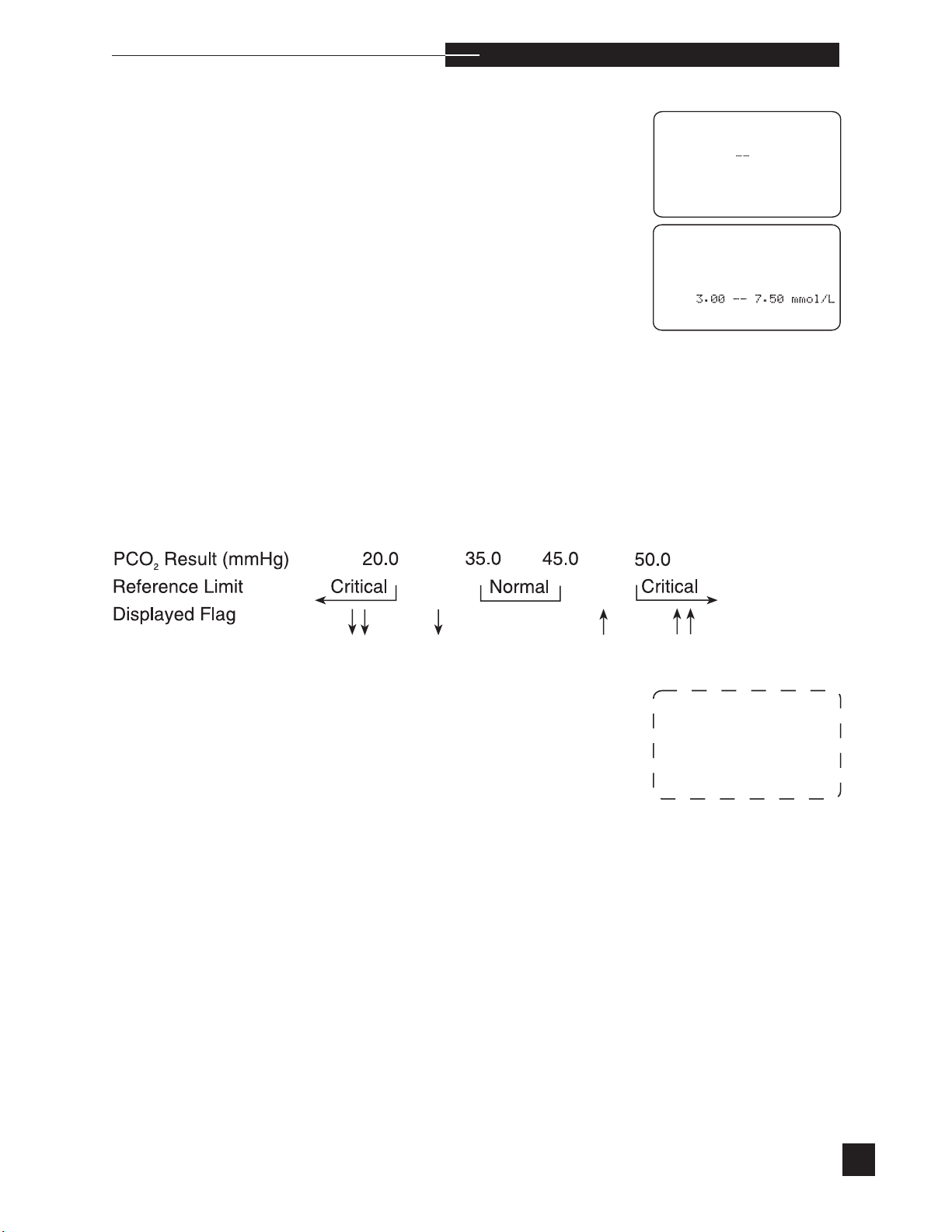
Na.0
150.0
mmol/L
Hct
33
70
%
SET REFERENCE LIMITS
CRITICAL
ARTERIAL
pH
7.300
7.600
PCO220.0
g
PO260
250
g
CONFIRM?
SET REFERENCE LIMITS
CRITICAL
ARTERIAL
K
Ca++0.82
mmol/L
CONFIRM?
o p e r a t i n g t h e a n a l y z e r
CRITICAL
Set the critical ranges for each parameter. Select arterial, mixed
venous, or venous. Press the number keys to enter the desired limits, and YES to confirm each individual setting and move to the next
location. When all limits are entered, press YES to CONFIRM?
to accept all entries. When NO is pressed as a response to
CONFIRM?, entries can be corrected.
When analysis results are in the critical range, they are flagged
as low (↓↓) or high (↑↑) on both the display and the printout. For
example, when the critical pH limits are 7.300 and 7.600, a ↓↓ flag
is displayed/printed for patient pH results less than or equal to 7.300
or a ↑↑ flag is displayed/printed for patient pH results greater than
or equal to 7.600.
Patient results that are outside the normal range, and not within the
critical range will be flagged as low (↓) or high (↑) on the display
and printout.
-- 50.0mmH
--
--
--
-- 3.00
r
mmH
RILIBAK
Set the RiliBAK target, percent deviation and range for each parameter. To change the setting, press NO to CONFIRM?. Press the
number keys to enter the desired limit and press YES to CONFIRM?
to accept all entries. When NO is pressed as a response to
CONFIRM?, entries can be corrected.
AMR
Set the Adjustable Measurement Range for each parameter. To
change the setting, press NO to CONFIRM?. Press the number keys
to enter the desired limit and press YES to CONFIRM? to accept
all entries. When NO is pressed as a response to CONFIRM?,
entries can be corrected.
sCa
++
is replaced with Cl- when Cl- mode is selected.
REFERENCE LIMITS 1/6
Rili-BAK LEVEL 1
LOT #XXXXXXX
pH
TARGET X.XXX mmHg
DEVIATION X.XX %
RILIBAK X.XXX
X.XXX mmHg
-
91
Page 98
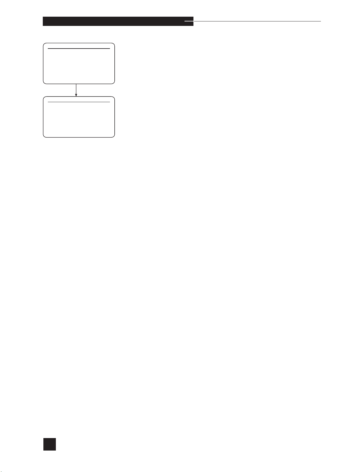
PATIENT INFORMATION
PATIENT ID
OFF
2 PATIENT TEMP
OFF
3 Hb
OFF
4 FIO
2
OFF
5 TIME DRAWN
OFF
CONFIRM?
PATIENT INFORMATION
2/2
SAMPLE TYPE
OFF
2 SAMPLE SITE
3 OPERATOR ID
OFF
OFF
o p e r a t i n g t h e a n a l y z e r
PATIENT INFORMATION
Turn patient information options ON or OFF for all samples. The
options are:
PATIENT ID, PATIENT TEMP Hb, FIO2, TIME
DRAWN, SAMPLE TYPE, SAMPLE SITE, OPERATOR
ID
Press the number keys to select and change an option. Press YES to
CONFIRM?.
When any options are turned ON, the EasyStat displays ENTER
PATIENT DATA? after sample aspiration. Press YES to enter
patient information. Use the number keys to enter values, and press
YES to advance to the next option. When all entries are correct, press
YES to CONFIRM?.
When Hb is turned on under PATIENT INFORMATION, THb
ss
is not displayed or printed as a calculated result.
When PATIENT ID is turned ON, a patient ID may be entered
for each patient sample. A maximum of 14 digits is accepted. The barcode reader may be used to enter the patient ID.
When PATIENT TEMP, Hb and FIO2 are OFF, the default
values (Patient Temp = 37°C, FIO2 = 21%) are used in the calculations.
92
Page 99
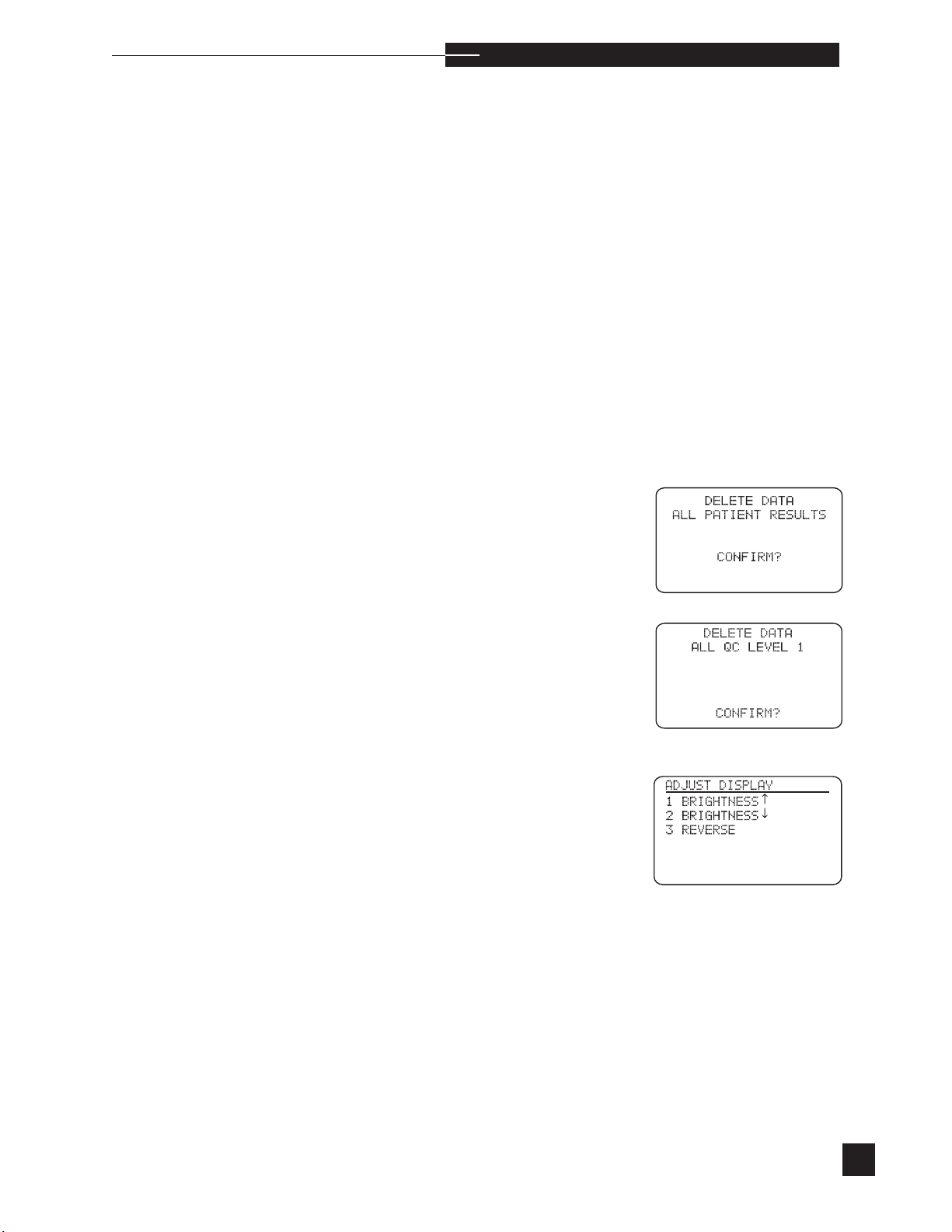
o p e r a t i n g t h e a n a l y z e r
When TIME DRAWN is turned on, the operator will be prompted
to enter the time the sample was drawn.
When SAMPLE TYPE is turned on, the operator is prompted to
select arterial, venous or mixed venous.
When SAMPLE SITE is turned on, the operator is prompted to
select brachial, femoral, arterial line cord or other.
When OPERATOR ID is turned ON, the operator will be prompted to enter an operator ID for each patient and quality control sample. A maximum of 14 digits is accepted. The barcode reader may be
used to enter the operator ID.
DELETE DATA
Delete all stored patient or quality control results.
r
ALL PATIENT RESULTS
Delete all stored patient results. Press YES to confirm deletion of all
patient results.
ALL QC LEVEL 1, 2 or 3, ALL HCT LEVEL 1, 2 ALL
PATIENT RESULTS
Delete stored quality control results or patient results.
Adjust Display
Adjust the brightness by continuing to press the number 1 or number
2 keys until acceptable. Reverse the contrast of the display by pressing
the number 3 key.
93
Page 100
5. Sample Handling and Collection
For complete sample handling and collection information, refer to a
textbook of standard clinical chemistry procedures.
Biohazard: Human body fluid specimens may be contaminated with HIV or other pathogens. Treat all specimens, collection devices and tools as biohazardous.
The patient’s status is extremely important when preparing to draw
an arterial blood specimen. Patients receiving certain drugs, such as
anticoagulants and thrombolytics, are at a greater risk for hematoma
or external bleeding. The correct puncture location and sample timing
is important in preventing bleeding.
s
Blood gas samples must be collected into syringes/ capillary tubes
containing heparin, including samples from patients receiving heparin
treatments. A final heparin concentration of 15-50 IU/mL is recommended. Calcium balanced heparin is recommended. Ammonium
heparin will shift the pH of the patient sample analyzed. Using sodium
heparin will increase the sodium level of the patient sample.
Syringe Sample
1 Draw blood into a syringe which is pretreated with liquid heparin
or use a prepackaged syringe treated with dry lyophilized heparin.
The syringe must be completely filled to assure the proper anticoagulation concentration. When preparing an untreated syringe,
only 0.05 mL of liquid heparin (1000 IU/mL) is necessary to anticoagulate 1 mL of blood. Too much heparin can alter the blood gas
values obtained. Make sure that no air bubbles are present before
sealing the syringe with an airtight cap. Note the time of
collection.
2 Mix the specimen with anticoagulant by gently inverting the
syringe several times. DO NOT SHAKE.
94
H
H
Failure to use the proper sampling materials and methods will result in
microclots which will degrade the system and result in reliability issues
such as PCO2 and PO2 electrode failures.
3 Analyze specimen within 5 minutes of collection, or immerse the syringe
barrel in an ice water bath. The ice water bath maintains an accurate
sample for up to 2 hours at a temperature between 1 and 5°C.
Note: Use only the Medica Capillary Kit. Use of other capillary tubes
may cause erroneous results, or damage to the analyzer and electrodes.
 Loading...