

Page 1

IP WEBCAM
Instruction manual
Remote Surveillance IP Camera
MT4009
Page 2

Table of Contents
1. Overview
1.1 General Overview ...............................................................................2
1.2 Product Applications .........................................................................3
1.3 Package Includes .................................................................................3
1.4 System Requirements ........................................................................3
2. Utilities And Tools
2.1 Cam EZ Search ......................................................................................3
2.2 MT4009 Exterior Function Introduction .....................................4
2.3 TV Out Function Introduction ........................................................5
3. Getting Start
3.1 System Login .........................................................................................5
3.2 Liveview ..................................................................................................6
3.3 Take A Shot ............................................................................................7
4. Advanced Function With Liveview
4.1 Image Adjustment .............................................................................8
4.2 Avi Record Setup ................................................................................8
4.3 Zoom In Display ..................................................................................8
4.4 Motion Detection Setup ..................................................................9
5. Advanced Application
5.1 Image Setup ..........................................................................................9
5.2 Capture View ...................................................................................... 10
5.3 Event Trigger ...................................................................................... 11
5.4 Network Setup ................................................................................... 11
5.5 Server Setup ....................................................................................... 13
5.6 Administration Setup ...................................................................... 14
5.7 Update .................................................................................................. 15
Appendix
Appendix A. Using a PPPOE Dial Up Connection and DDNS
with the MT4009 EZ IP WEBCAM (using a hub) .............................. 16
Appendix B. FAQ ....................................................................................... 22
2
1. Overview
1.1 General Overview
MT4009 is the most aff ordable and effi cient remote surveillance / security program available. It is extremely simple
to install, and can be used without a computer. With its internal web server, users can conduct remote video surveillance and security tasks from a web browser (such as IE or
Netscape), and quickly observe surveillance video feeds at
any time, anywhere from local network or Ethernet Internet connection.
The MT4009 combines CPU, CMOS Sensor Control, Image
processor, GPU, JPEG, CODEC, Ethernet MAC function that
is capable of 350,000 pps.
In addition, the system supports PPPoE, DHCP, Static IP,
DDNS, SMTP, FTP, NTP, and other types of network protocol,
and includes high effi ciency SDRAM control and memory
access. Also, the internal TV Out decoder / encoder devices
allow display of common household television formats
(supports NTSC and PAL). The system also includes fast
Motion Detection and SD expansion slot. The MT4009 has
Night Vision IR LED’s allowing it to see in the dark or assist
in low light situations. A professional grade remote surveillance and camera technology for many fun and security
purposes.
The MT4009 is the most aff ordable quality network surveillance and broadband camera system on the market, and it
is the most intelligent choice for business of all kinds.
Page 3

3
1.2 System Requirements
Minimum System Requirements
■ CPU: Intel Pentium 4® 2.0GHz or equivalent
■ Memory: 64MB (256MB recommended)
■ Operating System: Windows 98, Windows 2000® or Win-
dows XP®
■ Browser: Microsoft IE 6.0® and later
■ Hard Disk Space: 10MB Minimum
■ Network: 10/100Mbps Ethernet Port
1.3 Package Includes
1. IP WEBCAM
2. DC5V adapter
3. RJ-45 Red Cable(connect to PC)
4. RJ-45 Blue Cable(connect to internet)
5. TV Cable
6. CD-Rom
7. User’s Guide
8. Screw Bag
2. Utilities and Tools
2.1 CAM EZ SEARCH
CAM EZ Search is a searching application capable of searching for IP WEBCAM on the local network. The application
urges all IP WEBCAM to respond by sending out query
packets, and then displays a list of all IP WEBCAM available
on the network. In addition, CAM EZ allows the network
settings of a designated IP WEBCAM to be changed (such
IP address or name). CAM EZ can be used by following
these easy steps:
1. Open CAM EZ Search application.
2. Check to see if the IP addresses from the network are the
same as shown in CAM EZ Search: Go to Control panel
> Go to Network and Dialup Connection > Select the
settings for the local network connection being used
> Right click using your mouse > Select Preferences (P)
> Select Internet Protocol (TCP/IP) > Select Preferences
(R), and you can view the IP address for your computer.
If the settings are diff erent, you must update the IP settings for the MT4009 EZ IP WEBCAM. Do so as follows:
1.4 Product Applications
- IP WEBCAM - Web Server
- IP Surveillance - IP DVR
- Networking - Real-time Remote Monitoring
Surveillance - Value-Added IP
- IP Video Server Surveillance Device
TOP
Page 4

4
Step 1: Name: The user can rename the MT4009 EZ IP WEBCAM.
Step 2: IP: The IP address of the MT4009 EZ IP WEBCAM (for
example with a computer with an IP of 192.168.1.159, the
user would have to set the MT4009 EZ IP WEBCAM IP to
192.168.1.* (* = 1~254).
Step 3: Sub Mask (U): Usually set to 255.255.255.0
3. Step 4: Gateway: Change to correspond with the gateway settings of the network.
4. Step 5: HTTP Port: Change to 80
After settings are complete, press Submit, and the MT4009
EZ IP WEBCAM settings will take eff ect.
Press Update to update the MT4009 EZ IP WEBCAM menu.
Left click twice with your mouse on the desired name from
the list, and a browser window will open automatically,
displaying the CAM EZ Search network surveillance feed
icon:
2.2 MT4009 Exterior Function Introduction
Reset Switch button operation: When in operation, press
Switch button for 3 seconds the system will reboot. If you
press and hold down the SW button for longer than 5 seconds, the system will return to factory default settings.
TOP
Page 5

5
2.3 TV OUT Function Introduction
3. TV_OUT Operation :
■ Push to Ch-Flk: Press Reset switch button once, you can
adjust Ch-Flk 50Hz, 60Hz, Outdoor.
■ Hold to Exit: Press and hold down for 2 seconds, Exit ChFlk window.
Reset
Switch
TV OUT Default setting is NTSC system, please press
Reset switch and hold on for 3 seconds to change to
PAL system.
1. Connect the AV cable between TV set and IP WEBCAM as
the drawing.
2. Press RESET switch and plug in power adaptor at same
time, continuously hold on your press on RESET switch
for 2 seconds then release the press, the IP WEBCAM will
enter into “TV Out mode”.
3. Getting Start
3.1 SYSTEM LOGIN
System login is the process of identifying all people trying to log into the system, as to confi rm user identify, and
granting authorized users access to the system’s functions.
This system provides two layers of security access: “administer” and “general user”. After a successful login to the system, users can begin to access both surveillance and setting functions, follow the steps below:
Step 1: Open the login window, as shown below.
Directions: Using the
CAM EZ Search application, select the MT4009
EZ IP WEBCAM menu,
and click twice.
TOP
Page 6

6
Step 2: The system login window will appear in IE as
shown:
Step 3: Enter Account ID and Password
Step 4: Press “Submit” to confi rm, and the a network surveillance window shall appear, as shown:
Step 5: Enter “admin” as the Account ID, and “password” for
the password.
Step 6: If a mistake has been made, press “Cancel” , and enter login information again.
3.2 LIVEVIEW
When using IP WEBCAM for the fi rst time, users must
change the IE security settings (please refer to settings
step 3.2.1). Otherwise, the system will display the following warning, and be unable to display the surveillance
feeds.
After having successfully set up the IP WEBCAM settings
during the fi rst use,
users do not need
to change the settings again for later
use.
3.2.1 The IE security settings can be changed
by following the
steps below:
Step 1:
IE Toolbar ---> Tools -
--> Internet Settings
---> Security --->
Custom Settings (C)
TOP
Page 7
7
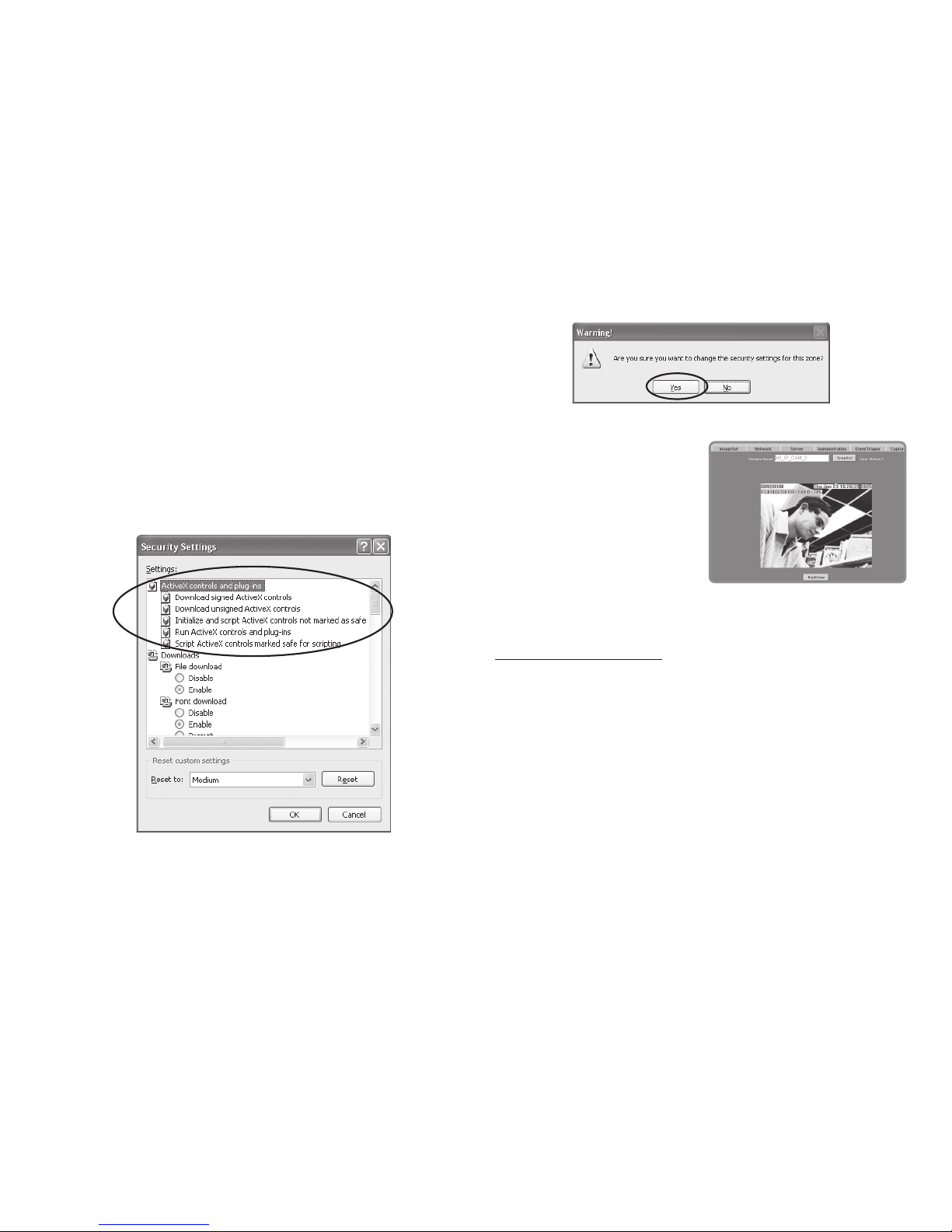
Step 2: After clicking on Custom Settings(C), a security settings window shall appear.
Change ActiveX Control Options and Plug-ins settings to
the following:
1. Download signed ActiveX controls: Enable
2. Download unsigned ActiveX controls: Enable
3. Initialize and script ActiveX controls not marked as safe:
Enable
4. Run ActiveX controls and plug-ins: Enable
5. Script ActiveX controls marked safe for scripting: Enable
Step 3: After pressing “OK”, a warning window shall appear.
Click on “Yes” (Y), and you shall return to the last window.
Press “OK”, and the setup is completed.
Step 4: At this time, the computer should display a warning
window then press “Yes” (Y).
Step 5: When completed,
you may begin viewing the
surveillance image for the
fi rst time as shown.
NOTE: This action loads ActiveX components from the
MT4009 System to a local machine.
3.3 TAKE A SHOT
This function allows users to capture the screen shot as a
photo, and save it on the computer.
Directions:
Step 1: Go to the “LiveView” menu, and go to the live image.
Step 2: Select an image, and hold down the Ctrl key.
Step 3: Place the cursor on the surveillance image and left
click with your mouse. The captured image should fl ash
momentarily: (or press the “Snapshot” button).
Step 4: Release the Ctrl key, and the single still shot image
has been successfully captured.
Step 5: Select the “CaptureView” menu to browse through
the captured images.
TOP
Page 8
8
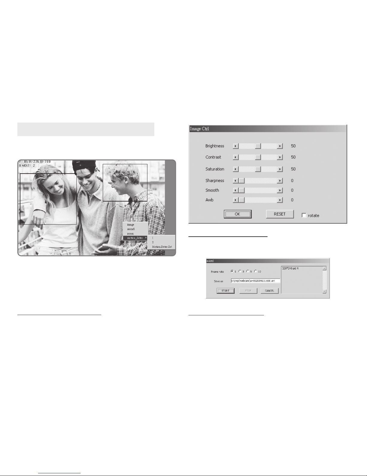
4. Advanced Function with LIVEVIEW
Move the cursor to the live image, and right click with your
mouse. A small menu should appear with four options.
Image: Adjust image values
Record: Setup for recording into AVI format.
Zoom: Select digital zoom value for window.
Motion Detec Set: Settings for motion detection
These settings are described in detail in the next chapter.
4.1 Image Adjustment
After selecting an Image, you may change various image
settings as shown:
4.2 AVI Record Setup
By selecting “Record”, you can adjust the AVI Frame Rate
settings and fi le name.
4.3 Zoom In Display
Using your mouse, select the portion of video that you
wish to view, and release. The image will zoom in according to the dimensions entered.
TOP
Page 9

9
4.4 Motion Detection Setup
Setting up the Motion Detection (MD) values, including
the fi rst set (red) and second set (green).
Please check to see whether the Event Trigger has been enabled. If so, you can set it up as described below:
Reset MD range: Select motion detect 1, and hold down
on the left mouse button (this will appear as the upper left
corner of the MD range). Then, drag out the desired range,
and release when fi nished.
Cancel MD: Same as above, but just left click once and release. This will cancel the MD (Motion Detection).
Motion detec set: This sets the MD (Motion Detection)
sensitivity, which is usually set to a value of 5. This means
that the motion detection will be toggled with as little of
a 5% change in the MD range. The lower the number entered, the higher the sensitivity of the MD.
When MD is engaged, the screen should display a MD
warning in the upper left hand corner if there is movement
within MD1 or MD2, as shown:
Any motion detection range can be selected in 640x480
and 320x240 resolutions
In 160x120 resolution, the motion detection is fi xed to the
entire image.
5. Advanced Application
This chapter explains the advanced settings for the MT4009
EZ IP WEBCAM, including:
- Image Setup - Event Trigger Setup
- Capture View - Administration Setup
- Network Setup - FW Update
- Server Setup
5.1 Image Setup
This includes:
■ Resolution: Users can select between image resolution
of 160x120, 320x240, and 640x480. The default resolution is 320x240.
■ Quality: Users can select between “fi ne”, “normal”, and
“basic” image quality. The default image quality is “basic”.
TOP
Page 10

10
■ Anti-Flicker: Users can select between 60Hz, 50Hz, or
Outdoor. The default setting is 50Hz. Please change to
“outdoor” when shooting outside.
■ Audio: Audio output. Default setting is “off ”.
■ Rotate 180: Image reverse. Default setting is “off ”.
■ IR Auto Detection: IR LED control. Default setting is “off ”.
Image Setup Directions:
Step 1:
Click on “ImageSet” to view the menu.
Step 2:
After entering the desired values, click on “Submit”.
Step 3:
If you wish to cancel your changes, click on “Cancel”.
5.2 Capture View
This view includes;
- Manual capture of still images using LiveView.
- Automatic capture of still images via MD.
How to Use Capture View:
Step 1:
Click on CaptureView to enter the menu.
The menu is capable of displaying up to 48 images, viewable on three pages.
Step 2:
You can set the system
to read from either your
computer or your fl ash
card.
After making your selection, click on “Apply”.
Step 3:
Select desired thumbnail image using the
cursor to view image at
the default dimensions.
TOP
Page 11
11
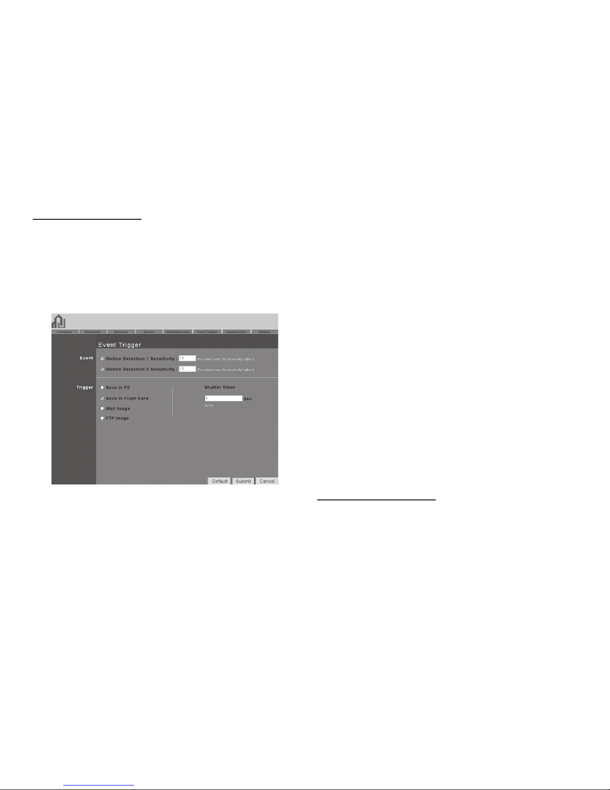
5.3 Event Trigger
This includes both event trigger settings and display, including:
- Event: Entering events
- Trigger: Setting trigger
and picture capture times.
Detailed explanations are presented in the next chapter.
How to Use Event Settings:
Step 1: Engage Event for either set (MD will automatically
display the trigger sensitivity)
Step 2: After you are fi nished, click on Submit.
Step 3: Otherwise, click on Default to use factory default
settings (all sets off )
NOTE: After engaging either type of event, “Save in PC”
will automatically turn on.
5.3.2 Trigger
Event trigger image transfer settings, including:
■ Save in PC: The image fi le is saved in your computer.
■ Save in Flash Card: The image fi le is saved in the SD
Card.
■ Mail Image: Send captured event trigger image fi le by
e-mail.
■ FTP Image: Send captured event trigger image fi le by
FTP.
■ Shutter Timer: Change shutter time for event trigger
image capture.
2 seconds is the default setting.
5.3.1 Event
Event settings, including:
- Motion Detection (set 1)
- Motion Detection (set 2)
Either set signal input trigger can be engaged.
5.4 Network Setup
Network Setup can be used to change the network connection settings of the IP WEBCAM. The default value for IP
assignment is “static”. These settings also include:
■ IP Assignment°GStatic,
■ DHCP, or PPPoE
■ PPPoE settings
TOP
Page 12

12
When using the “DHCP” setting, you do not need to enter
any of the above settings. You must only enter the address
of the DHCP Server in the “Server” fi eld.
When using the “PPPoE” setting, you must correctly enter
your ID and password. Please refer to unit 5.4.2 for details.
5.4.2 PPPoE
This menu allows you to enter the dial up settings during
PPPoE IP assignment. This usually refers to entering your
ID account name and password. Remember that you must
also enter your ISP settings as well.
How to Setup PPPoE
Step 1: Enter your correct user ID in the “Account” fi eld.
Step 2: Enter your correct password in the “Password” fi eld.
Step 3: Click on “Submit” to complete your settings.
NOTE: Because PPPoE utilizes a dynamic IP address
from an ISP, the IP settings for the MT4009 EZ IP WEBCAM could diff er for each use. It is thus suggested that
an IP Router be used to connect to the PPPoE or DDNS.
This will help your computer to fi nd the IP WEBCAM.
5.4.3 HTTP Server
This menu allows you to enter the port number of the
MT4009 IP WEBCAM internal web server
(or HTTP Server) via HTTP protocol. The default port number is “80”.
5.4.1 IP Assignment
Static IP Assignment refers to the fi xed settings of the ISP
or network engineering department.
IP Address: Includes static, DHCP, PPPoE. DHCP and PPPoE
are typically dynamic IPs.
When using the “static” setting, you must enter the following information:
■ IP Address: The IP address of the IP WEBCAM
■ Subnet Mask: Set by default to 255.255.255.0
■ Gateway: Default gateway
■ Http Server port settings
■ DNS settings
* MAC Address: Displays the Mac address of the IP WEBCAM
TOP
Page 13

13
5.4.4 DNS Server
This menu allows you to enter the IP address of the DNS
(Domain Name Server ).
By doing this, you can replace the IP address of the IP
WEBCAM with an http name (such as myIP WEBCAM.XXX),
making it easier to remember. The default DNS1 value is
“168.95.1.1” (Hinet). If the connection fails, the system will
automatically attempt to connect to DNS2.
5.5 Server Setup
This menu allows you to enter various server settings, including:
- Mail Server - DDNS Server
- FTP Server - NTP Server
5.5.1 Mail Server
This refers to settings pertaining to sending image fi les via
a mail server. You must also make sure that the Mail Image
settings from 5.3 EventTrigger are enabled to e-mail a fi le
to the designated address upon event trigger. This system
supports SMTP servers.
How to use mail server settings:
Step 1: Enter the IP address or http web address of the mail
server in “IP/Host”.
Step 2: Enter the e-mail address of the sender in “Mail
From”.
Step 3: Enter the e-mail address of the recipient in “Receipt
to”.
Step 4: Enter the registered account ID of the mail server
in “Account ID”.
Step 5: Enter the correct mail server password in “Password”
Step 6: Enter whether or not your mail server requires authorization in “Authorization”
Step 7: Click on Submit when you are fi nished.
5.5.2 FTP Server
This menu allows you to enter the FTP (File Transfer Protocol) Server settings. You must also make sure that the FTP
Image settings from 5.3 EventTrigger are enabled to send
a fi le to the designated FTP server via FTP upon event trigger. This system supports Port Mode and Passive Mode.
TOP
Page 14

14
How to use FTP Server settings:
Step 1: Enter the IP or HTTP address of the FTP server in
“IP/Host”
Step 2: Enter the designated FTP port number in “Port”
Step 3: Enter the account ID of the FTP server in “Account ID”
Step 4: Enter the FTP server password in “Password”
Step 5: Select whether you wish to use “Port Mode” or “Passive Mode” transfer protocol.
Step 6: Click on Submit when you are fi nished.
5.5.3 DDNS Server
This menu allows you to enter your DDNS(Dynamic Domain
Name Server) Settings. You can also use a PPPoE (with dynamic IP) to connect to the http address of the IP WEBCAM
(such as sqIP WEBCAM.dyndns.org) by entering the registered HTTP address of the DDNS Server. This is convenient
for viewing IP WEBCAMS with non-fi xed IP addresses.
Entering the DDNS Server Settings:
Step 1: Find a DDNS service (such as http://www.dyndns.
org ), and register a user account, password, and HTTP user
address.
Step 2: Enter the address (IP or HTTP) of the DDNS server.
Enter the host name, account ID, and password in each appropriate fi eld.
Step 3: Enter the account ID of the DDNS server in “Account ID”
Step 4: Enter the DDNS server password in “Password”
Step 5: Select the DDNS server connection status automatic display setting.
Step 6: Click on “Submit” when you are fi nished.
5.5.4 NTP Server
NTP(Network Time Protocol) allows you to calibrate the IP
WEBCAM timing.
Using the NTP Server settings:
Step 1: Enter the NTP Server IP or HTTP address in “IP/Host”
Step 2: Select the correct time zone in the “Time Zone”
menu
Step 3: Click on “Submit” when fi nished.
5.6 Administration Setup
This menu allows you to designate an IP WEBCAM name,
administrator password, and other user passwords. Administrators may access all IP WEBCAM functions and settings,
while general users may only utilize the LiveView view, and
may not access any of the settings.
TOP
Page 15

15
5.6.1 Camera Name
This allows you to set a IP WEBCAM name that will be displayed on the video for identifi cation purposes.
5.6.2 General User
This menu allows you to change the account ID and password for general users.
Using the General User settings:
Step 1: Enter the IP WEBCAM name in the “Account ID”
fi eld.
Step 2: Enter you’re the password you wish to change in
the “Old Password” fi eld.
Step 3: Enter the new password in the “New Password” fi eld.
Step 4: Confi rm the password by entering it once more in
the “Re-type”.
Step 5: Click on “Submit” to fi nish.
5.6.3 Administrator
This menu allows you to change the account ID and password for administrators.
Using the Administrator Settings:
Step 1: Enter the registered IP WEBCAM name in the “Account ID” fi eld.
Step 2: Enter you’re the password you wish to change in
the “Old Password” fi eld.
Step 3: Enter the new password in the “New Password” fi eld.
Step 4: Confi rm the password by entering it once more in
the “Re-type”.
Step 5: Click on “Submit” to fi nish.
5.7 Update
This menu allows you to update the IP WEBCAM software
(PV4.0_2.91.1 and up) online. You may use this feature to
update the internal
IP WEBCAM software so that you can make sure you have
the newest version available, as well as fi xes to any software glitches.
Using the Update Feature:
Step 1: The IP WEBCAM name is automatically detected
and displayed in the “Camera Name” fi eld.
Step 2: The IP WEBCAM software currently being used is
automatically detected and displayed in the “Current Version” fi eld.
Step 3: Enter the name of the software fi le (including directory) that you wish to update in “New File Name”.
TOP
Page 16

16
Step 4: You may also click “browse” to search for the fi le you
wish to update.
Step 5: Click “Submit” when you are fi nished.
Step 6: At this time, the system will begin to upload the fi le.
This should take 7-10 seconds for networks with 100Mbps
connections.
Step 7: The system will automatically begin a 50 second
countdown. If the process is successful, the words “Update
completed! System will auto reset after 3 seconds!” shall
appear.
Step 8: The system will return to the “System Login” screen.
Re-enter your Account ID and Password, and you’re fi nished.
Step 9: You may now check “Current Version” to make sure
that the update was successful.
NOTE: After completing Step 6, please do not disconnect the IP WEBCAM, or the unit may become damaged, and require to be taken back to the factory for
repairs.
Appendix
APPENDIX A.
Using a PPPOE dialup connection and DDNS with the
MT4009 EZ IP WEBCAM (Using a hub)
This section is intended to help users connect to a computer to the MT4009 EZ IP WEBCAM via a hub. It shall also
describe how to connect to ADSL with a PPPoE type IP address, and also how to connect to the MT4009 EZ IP WEBCAM using DDNS. The directions are as described below:
A. Apply for a DDnS account using your home computer.
B. Connect to the MT4009 EZ IP WEBCAM with your home
computer (using the CAM EZ Search Tool).
C. Setup your MT4009 EZ IP WEBCAM to connect via PP-
PoE, and enter your DDNS settings.
D. You may now view your EZ IP WEBCAM with DDNS viewer.
A. Applying for a DDNS Account with Your Home Computer
To do this, you must fi rst have a Cable/ADSL Ethernet
modem (with RJ-45 connectors), and make sure that your
TOP
Page 17

17
Step 3: Enter the desired account name (the account name
“mjIP WEBCAM001” is used in this example). Enter your Email address and password application. Click on “Create
Account” to complete the application.
Step 4: If the application is successful, the following shall
appear on your screen.
broadband provider (ISP) is properly connected to the Internet.
Step 1: Turn on your home computer, and connect to the
Internet.
Go to the http://www.dyndns.org/ website.
Step 2: Go to the “Account” Menu, and click on “Create Account”.
Step 5: After your application has been completed successfully, respond by E-mail to confi rm, and go back to http://
www.dyndns.org/ to enter your user name and password.
Step 6: Go to Dynamic DNS from the “Account” menu, and
click on “Add Host”. The following should appear:
Step 7: The “Services” menu should automatically appear.
Choose your Domain Name (gotdns.com has been used in
this example for your reference).
TOP
Page 18
18
Step 8: Enter your Host Name (mjIP WEBCAM001 has been
used in this example for your reference). Click on “Add
Host” to fi nish.
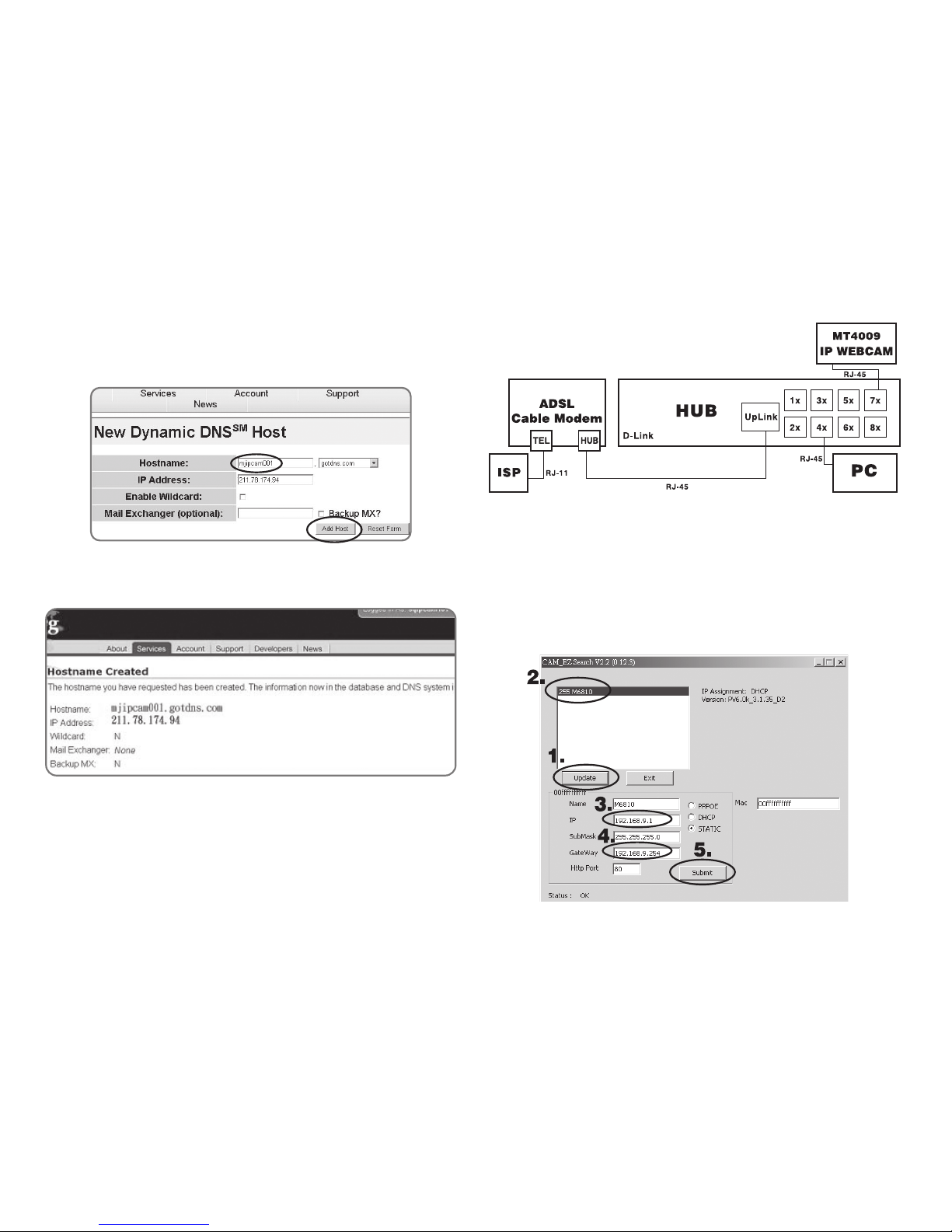
Step 9: After the new hostname has successfully created,
the following screen should appear:
B. Connecting to the MT4009 EZ IP WEBCAM with Your
Home Computer (Using the CAM EZ Search Tool)
Step 1: Please connect the MT4009 EZ IP WEBCAM to the
HUB as shown in following chart:
Step 2: Open CAM_EZ Search. Click on “Update” to begin
searching for any MT4009 EZ IP WEBCAM connected to
the local network. The menu should automatically display
the EZ IP WEBCAM under the name “MT4009”. It is recommended that you fi rst change its IP address to 192.168.9.1
(factory default). For gateway, it is recommended that you
use 192.168.9.253. Click “Submit” to update.
TOP
Page 19

19
Step 3: Go to My Computer > Control Panel
> Network and Dialup
Connection > Local
Connection > click on
“Properties (P)”.
Step 4: Select “Internet Protocol (TCP/IP)”, and click on the
Properties (R). Click on “Ok”.
Step 5: Change the IP Address to 192.168.9.2. Change Submask to 255.255.255.0. The default gateway is 192.168.9.254
(Change the IP address to any numbers within the range of
192.168.9.2 - 192.168.9.253). Click on “OK”
Step 6: In EZ Search Tool, click on Update once more to
search for IP WEBCAM on the local network. Double click on
“MT4009” from the list, and your browser will automatically
take you to the MT4009 EZ IP WEBCAM login window.
Please refer to P.8 for information on how to browse the
surveillance video from the MT4009 EZ IP WEBCAM.
Select
TOP
Page 20

C. Changing the MT4009 EZ IP WEBCAM Settings to PPPoE / Using DDNS
Step 1: Select “Network” to open the network menu. Enter
your account ID and password in the appropriate fi eld in
“PPPoE” (in this example, we have used Chung Hwa Telecom ADSL for your reference). Click on “Submit”.
Step 2: Go to the “Server” menu. Enter the host name, account ID, and password in the appropriate fi eld in “DDNS
Server”. Click on “Submit” to fi nish.
Step 3: At this time, you must change the IP settings of your
home computer back to their original values (automatically retrieve IP address). To do this, click on “Network Neighborhood”, right click on the Properties (R). Select your local
connection and right click to view the Properties (R).
20
TOP
Page 21

21
Step 4: Select “Internet
Protocol (TCP/IP)”, and
click on the Properties
(R). Click on “OK”.
Step 5: Select “automatically retrieve IP
Address (O)” and “Automatically retrieve
DNS server address
(B)”. Click on “OK”.
D. Using the MT4009 EZ IP WEBCAM with DDNS Viewer.
Step 1: Open CAM_EZ Search, and Click on Update. Wait for
about 60 seconds (actual time dependent on the quality of
your connection), and the MT4009 EZ IP WEBCAM should
be detected automatically. Click on the EZ IP WEBCAM to
view its IP and Gateway settings. If the system detects a
fl oating IP address, submask, or gateway that cannot be
changed, it means that the MT4009 EZ IP WEBCAM on the
local network has been successfully connected via a PPPoE
connection, as shown below:
1.
2.
3.
At this time, you may select the EZ IP WEBCAM that has
been detected. Your browser should automatically open to
the EZ IP WEBCAM login window.
TOP
Page 22

22
Step 2: You may also view the surveillance video from the
MT4009 EZ IP WEBCAM via a browser from a remote connection (such as your offi ce) by entering a preset DDNS
address (such as mjIP WEBCAM001.gotdns.com). asmjIP
WEBCAM001.gotdns.com).
APPENDIX B. FAQ
Q: Why is the time that is displayed on the image incor-
rect?
A: Make sure that the SNTP settings are correct, especially with
regard to the gateway connecting properly to the Internet.
Also, make sure that the SNTP Server that you entered is setup
correctly. The system should calibrate itself when fi rst connecting to the SNTP on startup, and then calibrate afterward once
every hour.
Q: Why can’t I update my IP Address?
A: Make sure that there are no other devices with the same IP Ad-
dress as the MT4009. If they are the same, try to connect the
MT4009 only to your computer to make sure there is no interference from any other device. You may then change your IP
Address.
Q: Why is it that the IP Search Tool can detect the MT4009,
yet my IE browser cannot?
A: This is because your IE browser settings are not set up to cor-
rectly browse the MT4009. We recommend that you turn off the
proxy server function.
To turn off the proxy server function in your IE browser, please
use the following procedure:
Go to Internet Settings (O) > Connection > Local Network Set-
tings (L) > Choose not to use proxy for the local network.
Q: Can mail be sent if “SD” is not selected?
A: Yes. The “Save in Flash Card” and “Mail Image” functions can be
conducted at the same time.
TOP
Page 23

23
Q: If we I forget my IP password or address settings, how
can I fi nd the IP Camera?
A: f you’ve forgotten your IP password or address settings, please
hold down the reset button for fi ve seconds to reset the system
to factory default.
Q: What should I do if mail cannot be sent out from the
MT4009?
A: f the system is unable to send mail from the MT4009 for any
number of reasons, the action will automatically be canceled,
and not be repeated.
Q: How can I connect to MT4009 IP WEBCAM from the my
offi ce?
A:
(1) Check your IE browser security settings.
IE Browser Tool bar > Tools > Internet Settings > Security.
Click on Custom Settings, and a security window will open up.
Change your ActiveX Control and plug in settings to match the
following:
1. Download signed ActiveX controls: Enable
2. Download unsigned ActiveX controls: Enable
3. Initialize and script ActiveX controls not marked as safe: Enable
4. Run ActiveX controls and plug-ins: Enable
5. Script ActiveX controls marked safe for scripting: Enable
(2) We recommend that you turn off the proxy server function. To
do this, please use the following procedure:
Go to Internet Settings (O) > Connection > Local Network Set-
tings (L) > Choose not to use proxy for the local network.
(3) In your IE browser, go to http://mjIP WEBCAM001.dyndns.org,
and connect to mjIP WEBCAM001. If the domain name is not
translated for any reason, go directly to the actual IP address:
211.78.174.94.
(4) After connecting to the System Login window for mjIP WEB-
CAM001, enter the account ID and password as shown below:
AccountID : user
PassWord : user
(5) While using mjIP WEBCAM001 for the fi rst time, you need to
install the ActiveX components.
This is why a warning should appear prompting you to install
the fi le HTTP://XXXX.XX..XX/view.cab. Click on “yes”.
(6) Please wait a moment for the ActiveX components to fi nish
installing. You should be able to view mjIP WEBCAM001 after
installation is completed.
TOP
Page 24

TOP
Page 25

IP WEBCAM
Instrukcja obsługi
Remote Surveillance IP Camera
MT4009
TOP
Page 26

Spis treści
1. Wstęp
1.1 Opis urządzenia................................................................................. 26
1.2 Zawartość opakowania .................................................................. 27
1.3 Wymagania systemowe ................................................................. 27
2. Oprogramowanie narzędziowe
2.1 CAM EZ SEARCH ................................................................................ 27
2.2 Opis funkcji zewnętrznych ............................................................ 28
2.3 Wyjście TV OUT.................................................................................. 29
3. Początek pracy
3.1 Logowanie do systemu .................................................................. 29
3.2 Podgląd obrazu ................................................................................. 30
3.3 Zdjęcie .................................................................................................. 31
4. Zawansowane funkcje podglądu
4.1 Ustawienie obrazu ........................................................................... 31
4.2 Ustawienie nagrywania AVI .......................................................... 31
4.3 Zbliżenie w podglądzie .................................................................. 31
4.4 Detekcja ruchu .................................................................................. 31
5. Aplikacje zaawansowane
5.1 Image setup ........................................................................................ 32
5.2 Capture View ...................................................................................... 32
5.3 Event trigger ....................................................................................... 33
5.4 Network setup ................................................................................... 33
5.5 Serwer setup ...................................................................................... 34
5.6 Administration setup ...................................................................... 35
5.7 Software update ............................................................................... 36
Dodatki
Dodatek A
Korzystanie z połączenia wdzwanianego PPPOE i DDNS........... 36
Dodatek B.
Rozwiązywanie problemów .................................................................. 38
26
Proszę uważnie przeczytać niniejszą instrukcję obsługi
przed instalacją urządzenia.
■ Nie można wystawiać kamery na ostre światło słońca,
gdyż może to być przyczyną uszkodzenia sensora optycznego.
■ Chroń kamerę przed zamoczeniem i wilgocią
■ Nie rozkręcaj. Demontaż, próby modyfi kacji w urządze-
niu lub naprawa przez nieautoryzowany serwis powoduje utratę gwarancji.
1. Wstęp
1.1 Opis urządzenia
Kamera MT4009 jest wszechstronnym ale prostym w obsłudze urządzeniem służącym do organizacji systemu podglądu pomieszczeń. Jest wyposażona w wysokiej klasy obiektyw z manualnym nastawem ostrości, czuły sensor CMOS
VGA, wbudowany mikrofon, gniazdo karty SD do zapisywania obrazów, wyjście TV OUT sygnału AV. Dzięki wbudowanym 6 diodom podczerwonym kamera może pracować
nawet przy kompletnym zaciemnieniu, co ma szczególne
znaczenie w przypadku monitoringu pomieszczeń po godzinach pracy. Funkcja detekcji ruchu pozwala na nagrywanie wyłącznie zdarzeń a nie „pustej” przestrzeni.
Kamera komunikuje się z komputerami za pośrednictwem
sieci Ethernet. Wbudowany serwer WEB umożliwia szybkie
i łatwe zdalne zarządzanie także z sieci WAN. Jeżeli lokalna
sieć komunikuje się ze światem zewnętrznym za pomocą
TOP
Page 27

27
1.3 Wymagania systemowe
■ Procesor Pentium 4 2GHz
■ 256 MB RAM
■ 10 MB wolnego miejsca na dysku
■ Port USB 2.0 lub 1.1
■ Przeglądarka WWW
■ Microsoft® Windows® ME/2000 / XP
■ Karta sieciowa Ethernet 10/100
2. Oprogramowanie narzędziowe
2.1 CAM EZ SEARCH
dostępnej sieci lokalnej kamery IP. Aplikacja wysyła w sieci
zapytania zmuszając kamery do podania swojego adresu
IP, który następnie wyświetlany jest na liście. CAM EZ SEARCH umożliwia również zdalną zmianę parametrów adresowych urządzenia.
Oto przykład zastosowania w kilku prostych krokach:
1. Uruchom z płyty CD aplikację CAM EZ SEARCH
2. Sprawdź czy adresy IP pochodzące z sieci są zgodne
ze wskazaniem aplikacji. Adres IP komputera możesz
sprawdzić w Panelu Sterowania pod ikoną Połączenia
sieciowe, wybierając Właściwości protokołu TCP/IP. Jeżeli numeracja IP twojej sieci będzie inna niż fabryczne
ustawienia kamery, proszę wykonać następujące kroki:
Krok 1: W polu Name ustaw dowolną nazwę kamery
Krok 2: W polu IP określ lokalny numer IP właściwy dla
1. Kamera IP
2. Zasilacz
3. Czerwony kabel RJ-45
(podłączenie bezpośrednio do PC, tzw. przeplot)
4. Niebieski kabel RJ-45
(podłączenie do przełącznika sieciowego)
5. Kabel TV
6. Płyta z oprogramowaniem
7. Instrukcja obsługi
8. Akcesoria montażowe
dynamicznego numeru IP, istnieje możliwość przeglądania
przez WWW obrazów po uprzednim, bezpłatnym wybraniu adresu DYNDNS.
1.2 Zawartość opakowania
TOP
Page 28

28
architektury twojej sieci LAN (np. jeżeli Twój komputer
ma numer IP: 192.168.1.159, to kamera powinna mieć
numer 192.168.1.* , gdzie * jest liczbą w przedziale od
1 do 254 z wyjątkiem 159). Zwróć uwagę aby nie ustawić numeru już znajdującego się w sieci, gdyż wywołasz
konfl ikt adresów.
Krok 3: SubMask wpisz maskę podsieci
(zwykle 255.255.255.0 lub spytaj administratora)
Krok 4: Gateway: wpisz adres właściwy dla bramki inter-
netowej w twojej sieci
Krok 5: Http Port: zwykle 80 o ile administrator sieci nie
zmienił na inny
3. Po wpisaniu wszystkich danych kliknij przycisk „Submit”
aby zapisać dane w pamięci kamery.
4. Naciśnij „Update” aby odświeżyć listę programu
2.2 Opis funkcji zewnętrznych
Funkcja przycisku reset:
Naciśnij i przytrzymaj 3 sekundy, a system kamery wystartuje od początku. Przytrzymanie przez 5 sekund powoduje
zresetowanie ustawień kamery do wartości fabrycznych.
TOP
Page 29

29
2.3 Wyjście TV OUT
3. Obsługa w tryb TV OUT:
■ zmiana warunków oświetleniowych: naciskając reset
zmień parametry na 50Hz, 60Hz lub oświetlenie naturalne
■ przytrzymaj reset 2 sekundy aby wyjść z menu ustawień
światła
Przycisk
reset
Fabryczne ustawienie sygnału wizji w wyjściu TV OUT
to NTSC. Po podłączeniu do odbiornika sygnału video,
naciśnij reset na 3 sekundy aby zmienić system na PAL.
1. Podłącz kamerę do odbiornika tak jak na schemacie
2. Wciśnij reset i równocześnie podłącz wtyczkę zasilania.
Trzymaj reset jeszcze 2 sekundy aby przełączyć kamerę
w tryb TV OUT
3. Początek pracy
3.1 Logowanie do systemu
Logowanie do systemu to proces autoryzacji użytkownika
umożliwiający dostęp do funkcji i ustawień urządzenia. System oferuje dwa poziomy dostępu: administrator i general user. Po zalogowaniu do systemu użytkownicy w zależności od statusu mają dostęp do podglądu i ustawień:
Krok 1: Kliknij dwukrotnie nazwę kamery na liście w programie CAM EZ SEARCH
TOP
Page 30

30
Krok 2: W przeglądarce pojawi się okno logowania
3.2 Podgląd obrazu
Przy pierwszym użyciu kamery, może być konieczna zmiana ustawień zabezpieczeń IE. W przeciwnym wypadku
zostanie wyświetlony komunikat błedu ActiveX. Zmiany
dokonuje się raz.
3.2.1 Zmiana ustawień zabezpieczeń przeglądarki IE
Krok 1: Z menu przeglądarki wybierz: Narzędzia > Opcje
internetowe > Zabezpieczenia > Poziom niestandardowy
Krok 2: Na liście odszukaj grupę „Formanty ActiveX i dodatki plug-in”. Następujące opcje w tej grupie powinny zostać
włączone:
1. Pobieranie podpisanych formantów ActiveX
2. Pobieranie niepodpisanych formantów ActiveX
3. Inicjowanie i wykonywanie skryptów formantów ActiveX nie zaznaczonych jako bezpieczne
4. Uruchamianie formantów ActiveX i dodatków plug-in
5. Zachowania elementów binarnych i skryptów
Krok 3: Po potwierdzeniu „OK.” pojawi się okno ostrzeżenia,
gdzie również należy odpowiedzieć „TAK”. Ustawienie zostało dokonane
Krok 4: Za każdym razem gdy IE przy próbie podglądu kamery wyświetli okno ostrzeżenia, naciśnij „TAK”.
Krok 5: Od tego momentu oglądanie obrazu w przeglądarce IE nie będzie problemem
Krok 3: Podaj login i hasło
Krok 4: Po naciśnięciu przycisku „Submit” powinno pojawić
się takie okno:
Krok 5: Podaj w pola Acount ID: admin a w polu Password:
password
Krok 6: W przypadku błędu kliknij Cancel i podaj dane ponownie
TOP
Page 31

31
3.3 Zdjęcie
Funkcja ta umożliwia zachowanie pojedynczej klatki jako
zdjęcia i zapisanie jej w komputerze w postaci pliku grafi cznego
Krok 1: Przejdź do menu „LiveView” w celu wyświetlenia
podglądu obrazu
Krok 2: Wybierz kursorem myszy obraz i wciśnij i przytrzymaj klawisz CTRL
Krok 3: Naciśnij przycisk „Snapshot”
Krok 4: Puść CTRL. Wybrana klatka została zapisana
Krok 5: Zapisane obrazy znajdziesz w przeglądarce menu
„CaptureView
4. Zawansowane funkcje podglądu
Po kliknięciu prawym przyciskiem myszy na ruchomy obrazie podglądu zostanie wyświetlone podręczne menu
Image: Ustawienia parametrów obrazu
Record: Ustawienie nagrywania AVI
Zoom: Zbliżenie w podglądzie
Motion Detec Set: Ustawienia detekcji ruchu
4.1 Ustawienie obrazu
Wybranie tej opcji umożliwia ustawienie parametrów obrazu takich jak np. jasność, kontrast, nasycenie itp.
4.2 Ustawienie nagrywania AVI
Umożliwia zmianę szybkości obrazu (frame rate) oraz nazwy i lokalizacji zapisywanego pliku AVI
4.3 Zbliżenie w podglądzie
Zaznacz kursorem myszy interesujący cię fragment obrazu
a zostanie on powiększony
4.4 Detekcja ruchu
Ustawienie detekcji ruchu (MD) obejmuje dwa zestawy
pola: zestaw 1 (czerwony) i zestaw 2 (zielony). Upewnij się
że funkcja zdarzeń (event trigger) jest włączona.
Reset MD range: zaznacz obszar 1 w jakim ma się odbywać wykrywanie ruchu
Cancel MD: obsługa odbywa się podobnie, jednak zaznaczony obszar będzie wyjęty spod detekcji ruchu
Motion detec set: ustawienie czułości detekcji. Im niższy
numer tym większa czułość detekcji ale też większa możliwość pomyłek.
TOP
Page 32

32
Kiedy detekcja ruchu zostanie wzbudzona, na ekranie pojawi się informacja w którym obszarze został wykryty ruch
■ IR Auto Detection: automatyczna kontrola diod pod-
czerwieni, standardowo wyłączone (off )
■ w rozdzielczościach 640x480 i 320x200 może zostać
ustawiony każdy poziom czułości detekcji
■ w rozdzielczości 160x120 czułość jest stała i niezmienna
5. Aplikacje zaawansowane
W tym rozdziale zostały opisane aplikacje wchodzące w
skład wbudowanego w kamerę systemu
5.1 Image setup
■ Resolution: możliwość wyboru jednej z rozdzielczości
obrazu: 160x120, 320x200 lub 640x480
■ Quality: ustawienie jakości obrazu: fi ne, normal, basic
(fi ne – najlepszy obraz ale najwolniejszy)
■ Anti-Flicker: ustawienie warunków oświetleniowych:
60Hz, 50Hz lub Outdoor (światło naturalne)
■ Audio: włączenie/wyłączenie mikrofonu
■ Rotate 180: odwrócenie obrazu
Po ustawieniu parametrów naciśnij „Submit” aby zapisać
zmiany
5.2 Capture View
W tym miejscu znajdują się obrazy zapisane
bądź to w wyniku ręcznego przechwycenia
(snapshot) lub automatycznego przez detekcję ruchu
TOP
Page 33

33
Możesz wybrać skąd mają być pobierane obrazy (PC lub
Flash card), co należy zatwierdzić przyciskiem „Apply”. Kliknięcie na wybraną miniaturę powoduje wyświetlenie obrazu w pełnym rozmiarze.
5.3 Event trigger
Ekran podzielony jest na 2 sekcje:
Event: aktywacja oraz ustalenie czułości obszarów wykrywania typu 1 i 2. Im niższa wartość tym większa czułość
Trigger: określenie postępowania z wykrytym zdarzeniem
Mail image: obrazy będą wysyłane na wskazany adres e-
mail
FTP image: obrazy będą wysyłane na wskazany adres FTP
Shutter timer: ustawienie przedziału czasu w jakim ma być
podejmowana akcja
5.4 Network setup
W tym miejscu znajdują się wszelkie ustawienia parametrów sieciowych kamerach takie jak adresy, maska podsieci, serwery DNS itp
Save in PC: obrazy będą zapisywane bezpośrednio na
komputerze
Save in Flash Card: obrazy będą zapisywane na karcie
pamięci
TOP
Page 34

34
5.4.1 IP Assignment
Tu należy określić rodzaj adresu (typ obecności w sieci).
Należy wybrać jeden z rodzajów adresu: Statyczny (static) – numer zewnętrzny przypisany przez operatora ISP,
Dynamiczny DHCP (adres przydzielany automatycznie w
przez serwer DHCP) lub dynamiczny z połączenia wdzwanianego PPPoE (również nadawany automatycznie przez
zewnętrznego operatora).
Używając numeru statycznego należy podać numer IP, maskę podsieci oraz bramkę internetową
5.4.2 PPPoE
W przypadku gdy kamera ma się łączyć z Internetem za
pomocą połączenia wdzwanianego, należy podać login i
hasło dostarczone uprzednio przez operatora
5.4.3 HTTP Server
Ustawienie portu danych HTTP, standardowo 80. Nie zalecamy zmiany tego parametru, chyba, że ma to służyć dodatkowemu ukryciu kamery w sieci
5.4.4 DNS Server
W tej części należy podać przynajmniej jeden adres DNS
(Domain Name Serwer), dzięki czemu kamera będzie możliwa do znalezienia w sieci po dowiązaniu do adresu internetowego (w przypadku DHCP, DNS są również pobierane
automatycznie).
5.5 Serwer setup
W tej części znajdują się ustawienia sieciowe serwera kamery odpowiedzialnego m.in. za dystrybucję obrazu
5.5 Serwer setup
W tej części znajdują się ustawienia sieciowe serwera kamery odpowiedzialnego m.in. za dystrybucję obrazu
5.5.1 Mail Server
W tej części znajdują się dane dotyczące serwera pocztowego, dzięki któremu będzie możliwe przesyłanie powiadomień o wykrytym ruchu. System obsługuje serwery
SMTP.
TOP
Page 35

35
W odpowiednie pola należy wpisać dane istniejącego konta poczty elektronicznej:
IP/Host – podaj adres lub numer IP serwera pocztowego
Mail from – podaj adres wysyłającego
Receipt to – podaj adres adresata (dokąd ma być wysłany
mail)
Account ID – podaj login właściciela konta
Password – podaj hasło dostępowe do konta
Authorization – włącz jeżeli Twój serwer wymaga autory-
zacji
5.5.2 FTP Server
W tej części znajdują się dane dotyczące serwera FTP, dzięki któremu będzie możliwe przesyłanie powiadomień o
wykrytym ruchu na adres FTP. System obsługuje tryb pasywny (jak w przeglądarce WWW) oraz tryb portu.
W odpowiednie pola należy wpisać dane istniejącego konta FTP:
IP/Host – podaj adres lub numer IP istniejącego
serwera FTP
Port – podaj port (zwykle 21)
Account ID - podaj login właściciela konta
Password – podaj hasło
FTP Mode – wybierz tryb pasywny lub tryb portu
5.5.3 DDNS Server
W tej części znajdują się dane dotyczące serwera DDNS
(Dynamic Domain Name Server), dzięki któremu będzie
możliwy dostęp do podglądu obrazu z kamery po wpisaniu wcześniej ustalonego adresu DDNS, bez konieczności
podawania numeru IP. Adres DDNS jest również niezbędny,
w przypadku gdy kamera znajduje się w sieci LAN z dynamicznie przydzielanym zewnętrznym numerem IP.
W celu pozyskania adresu DDNS należy skorzystać z jednego z serwisów oferujących takie adresy, np. www.dyndns.org, gdzie należy utworzyć konto i wybrać sobie adres.
Dane dostępowe tego konta należy wpisać we właściwych
polach części DDNS Server.
5.5.4 NTP Server
NTP (Network Time Protocol) umożliwia automatyczne kalibrowanie czasu w kamerze
IP/Host – podaj adres lub numer IP jednego z serwerów
NTP
Time Zone – określ strefę czasową w której znajduje się
kamera
5.6 Administration setup
Tutaj należy określić parametry konta administratora, który
będzie miał dostęp do wszelkich ustawień kamery, łącznie
z możliwością dodawania i usuwania użytkowników
5.6.1 Camera Name
Nazwa kamery do celów identyfi kacyjnych
5.6.2 General User
W tym polu należy podać dane konta głównego użytkownika (login i hasło). Każdy użytkownik logując się z Inter-
TOP
Page 36

36
netu, chcąc uzyskać dostęp do podglądu kamery będzie
musiał się zalogować
5.6.3 Administrator
W tej części znajdują się dane konta administratora. Po ich
podaniu należy je dobrze zapamiętać. W przypadku zapomnienia lub pomyłki nie będzie możliwe wejście do panelu administracyjnego. W takim wypadku konieczny będzie
twardy reset kamery (5 sek. przytrzymany przycisk reset) i
powrót do ustawień fabrycznych.
5.7 Software update
W tej części można zaktualizować fi rmware kamery (wewnętrzne oprogramowanie). Jeżeli producent udostępni
nowszą wersję oprogramowania niż znajdujące się w kamerze, należy plik z aktualizacją ściągnąć na pulpit dowolnego komputera w sieci. Następnie zalogować się jako administrator i w polu New Filename podać ścieżkę do pliku
oraz potwierdzić naciśnięciem „Submit”. Proces aktualizacji
trwa ok. 7-10 sekund, po tym czasie ok. 50 sekund trwa ponowna aktywacja systemu.
Ważne. W trakcie aktualizacji fi rmware nie wolno odłączać
kamery od sieci LAN lub zasilania, gdyż może to trwale
uszkodzić kamerę.
Dodatki
Dodatek A.
Korzystanie z połączenia wdzwanianego PPPOE i DDNS
(podłączenie do koncentratora)
W tym rozdziale opisano przykładowe połączenie kamery
z komputerem z zastosowaniem koncentratora sieciowego, połączenia wydzwanianego szerokopasmowego ADSL
prze PPPoE, a także jak skorzystać z adresu DDNS
A. Założenie konta DDNS
Rejestracja jak i utrzymywanie adresów jest bezpłatne.
1. Wejdź na stronę http://www.dyndns.org i przejdź do
menu „Account”
2. Kliknij link „Create account”
3. Wypełnij ankietę w tym nazwę użytkownika (username) i dres e-mail. Zrób to dokładnie, i podaj prawdziwe
dane, w przeciwnym wypadku nie będziesz mógł się
potem zalogować.
4. Jeżeli wypełniłeś formularz poprawnie otrzymasz informację zatytułowaną „Account created”
5. Na podany wcześniej adres e-mail otrzymasz wiadomość z linkiem potwierdzającym rejestrację konta.
6. Zaloguj się na stronie http://www.dyndns.org w części
„Account”. Jeżeli wszystko przebiegło bez problemów
powinieneś widzieć swoje dane jak i menu dostępnych
funkcji
TOP
Page 37

37
7. Kliknij link „Dynamic DNS (Add Host)”
8. W menu “Services” wybierz jedną z wielu dostępnych
darmowych domen
9. W polu „Hostname” wpisz nazwę kamery, będzie ona
jednocześnie początkiem adresu w wybranej domenie,
a w polu IP Adres podaj zewnętrzny numer IP kamery
10. Po poprawnym utworzeniu adresu DDNS pojawi się
taki komunikat:
B. Podłączenie kamer do komputera z zastosowaniem
koncentratora i modemu ADSL.
Poniższy schemat ilustruje przykładowy
(najczęściej stosowany) sposób podłączenia
kamery w sieci LAN.
Do wyszukania kamery w sieci należy użyć programu CAMEZ SEARCH, opisywanego na początku instrukcji.
C. Ustawienie parametrów PPPoE oraz DDNS w panelu
administratora
1. Zaloguj się jako administrator do systemu kamery i
przejdź na stronę „Network Setup”. W części PPPoE podaj
login oraz hasło dostępowe do połączenia dostarczone
przez operatora Internetu. Kliknij „Submit”
2. Przejdź na stronę „Serwer Setup”. W części DDNS Server
podaj pełny przyznany adres DDNS, zarejestrowany login oraz hasło. Kliknij „Submit”
TOP
Page 38

38
Dodatek B.
Rozwiązywanie problemów
P: Dlaczego czas wyświetlany na podglądzie jest nie-
właściwy?
O: Upewnij się, że poprawnie podałeś parametry dostępo-
we do Internetu (np. bramę internetową). Upewnij się, że
wszystkie dane jak i adres serwer NTP są poprawne. Odczekaj co najmniej 2 godziny. Zegar powinien się skalibrować,
jeżeli połaczenie z Internetem jest właściwe
P: Dlaczego nie mogę zmienić adresu IP?
O: Upewnij się, że w sieci nie występuje inne urządzenie o tym
samym adresie. Spróbuj podłączyć kamerę bezpośrednio
do komputera (czerwony kabel RJ-45) i dokonać zmiany
P: Dlaczego program IP Search Tool znajduje kamerę,
ale pod przeglądarką jej nie widać
O: Proszę sprawdzić ustawienia sieci w przeglądarce Internet
Explorer. Jeżeli jest włączony Proxy Server, należy go wyłączyć
P: Zapomniałem hasła oraz numeru IP kamery.
O: Najprościej wykonać reset kamery przez naciśnięcie i przy-
trzymanie przez 5 sekund przycisku reset. Kamera powróci
do ustawień fabrycznych.
TOP
 Loading...