

Page 1

MediaLas Laserproducts GmbH 1/50
Page 2
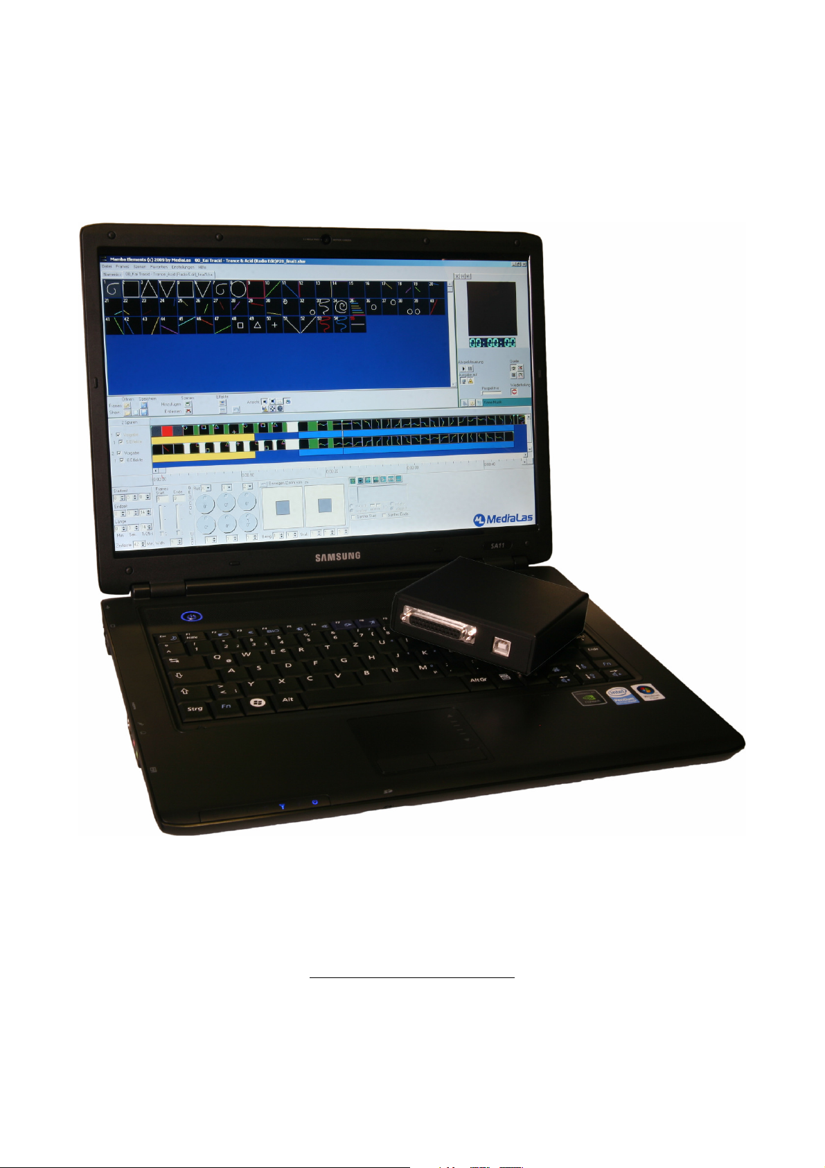
This manual is meant as an overview for the various Mamba Elements functions, and might not be fully accurate to the
latest version and release of Mamba Elements. MediaLas will try to update this manual as often as possible. Please use
also the "what´s new" papers and documentations for most actual enhancement and releases.
Release of this Manual: Jan 16, 2009
MediaLas Laserproducts GmbH 2/50
Page 3

Here, at MediaLas, we truly believe that Laser is the world´s most beautyful lighting entertainment
technology today. We do not mean to disrespect or degrade any other lighting effect, but the
homogenous coherent light beam of a laser is the most unique lighting entertainment effect ever
created.
“Everything we do is dedicated to the laser light”, founder and president of MediaLas, Dirk Baur,
says. "We envision a world where those who work with lasers in live shows and presentations can
bring out the very best from any performance, and where the possibilities of laser light
performances are endless."
Our mission is lead by a simple rule:
Bring the best performance at highest possible level for a humanized and affordable cost.
So this is how we create our show laser tools. This is how we created legends like CATWEAZLE
scanner, Mystiqe showlasers, or the new thrilling and freshly awarded Infinity showlaser system. It
also means, that there is a group of engineers and technicians, research specialists and laserists
sitting in Balingen/Germany, who spend most of their living time on the dedicated love to laser
lights. This passion creates legends!
Our products focus on removing barriers and bringing the best possible laser technology with
inspiring creativity in performance. Check out our range and features on our website, or visit us
during a demo day or trade show worldwide!
Copyright Notice
Mamba Elements and Mamba Elements are trademarks of MediaLas Germany. All unauthorized
copy or manipulation of the software is prohibited and will be prosecuted by international law.
License policy for Mamba Elements Laser Software
Mamba Elements comes with a dongle key ( MediaLas QuickPort ) for software protection. This
dongle key is one full software license! If this key gets lost, a new software license must be
purchased! So please be careful with your dongle key, do not lose it.
Furthermore, your personal software version is coded for your personal dongle key only! It is NOT
possible, to have other Mamba Elements software versions running with your dongle key. If your
software starts up, but closes again after a few seconds, Mamba Elements did not find the
appropriate key, and will not start up. This was done for two reasons:
• To avoid theft on your stage system – thiefs cannot use a solo dongle key, since they need
the appropriate software for it, so there is no need to steal a dongle key
• To easily transport your license from one computer to the other. In this way, you can install
the software as many times as you want, on any computer you like.
MediaLas Laserproducts GmbH 3/50
Page 4
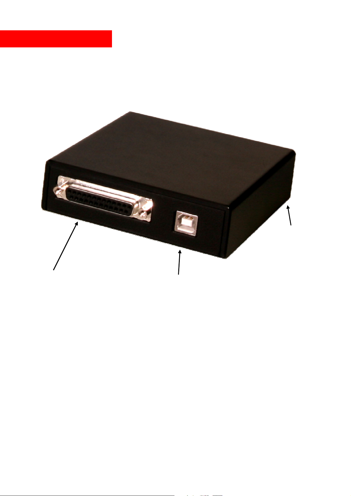
MediaLas QuickPort
• High speed USB-to-Laser interface for Mamba Elements software system.
• Transfer up to 1MB per second ensures a very smooth and fast output of up to 100,000 pps.
• ILDA output connector with full XY, blank and RGB.
• Easy driver installation
• USB - powered
• small construction
operation LED
ILDA connector (to laser):
Pin 1 X+
Pin 2 Y+
Pin 3 blank/intensity +
Pin 4 interlock
Pin 5 red +
Pin 6 green +
Pin 7 blue +
Pin 13 shutter
Pin 14 XPin 15 YPin 16 blank/intensity –
Pin 17 interlock
Pin 18 red Pin 19 green Pin 20 blue Pin 25 ground
USB connector (for PC)
MediaLas Laserproducts GmbH 4/50
Page 5
About this manual
The following content describes the various functions of Mamba Elements laser software. Due to
the fact, that Mamba Elements is updated constantly, not all functions will be described properly.
Please check the Mamba Elements support site for actual manual updates, or simply check online
with Help/Check for updates.
This manual is split into different categories:
- Setup and installation of Mamba Elements software
- Main frame editor and frame editing functions
- Show creation by using the tracks on the timeline
- Setting up Mamba Elements to your laser projector and/or interface
- Import/export shows and frames
- Live player in Mamba Elements
- VST Video Sequence Tracing software
Mamba Elements users, which are interested in adding content to the manual,
are greatly welcome to send us their doc files with updated content. After
reviewing, we are happy to add your input to the most actual Mamba Elements
manual. Of course, your input will be marked with the name of the originator
and creator. So if you want to see your name in this manual, and present
yourself to the community as an experienced Mamba Elements user and show
creator, you are welcome to join the great Mamba Elements community and
help, to make this manual better than any other manual in the world. Simply
send your edition or changes to [email protected] , either in a plain .txt
file, or use a pdf editor, to add some info or data to this pdf document. .
MediaLas Laserproducts GmbH 5/50
Page 6
Hardware required
To run Mamba Elements properly, the following setup of hard- and software is recommended:
Processor speed: > 1.5GHz. recommended 2 GHz or more
Memory: min. 512MB, recommended >1GB, optimum 2GB or more
Graphics adaptor: Fast 3D adaptor recommended
Harddisk space: Approx 500MB
Screen resolution: min 1024 x 768, recommended 1280x 1024 or better
Operating system: Win 2000 or Win XP SP2/SP3 or Windows Vista
USB Ports: Min 2. Maximum 2 USB interfaces per port.
Installation
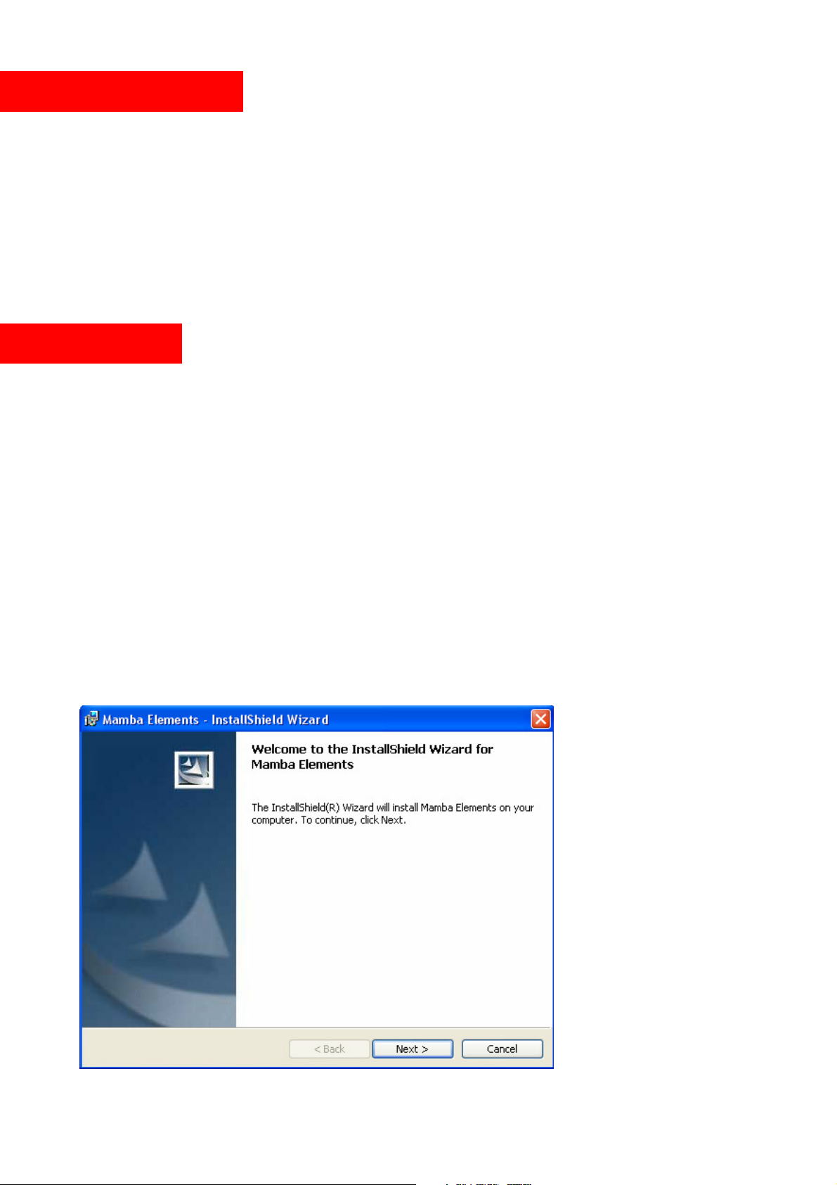
Installation of Mamba Elements is quite easy. During the installation process, necessary drivers for
dongle key or USB Interface will be copied and installed after connecting the desired hardware. So
if you did not connect the USB Box before starting Mamba Elements, you might get an error
message on the screen. Discard this message, it will not interfere with proper function of Mamba
Elements.
With the Mamba Elements installation package, you will receive two disks. One is the program
disk, also holding shows and frames, and the second is your licence disk, which corresponds to your
dongle key serial number. Please note, that the software does work with your dongle key. ONLY It
will NOT WORK with any other dongle key. Each single key is licenses and compiled to the
software version on your disk.
If you run more than one version of Mamba Elements, make sure not to mix up your dongle keys.
Insert Mamba Elements program CD into your disk drive.
© MediaLas Laserproducts GmbH 6/50
Page 7
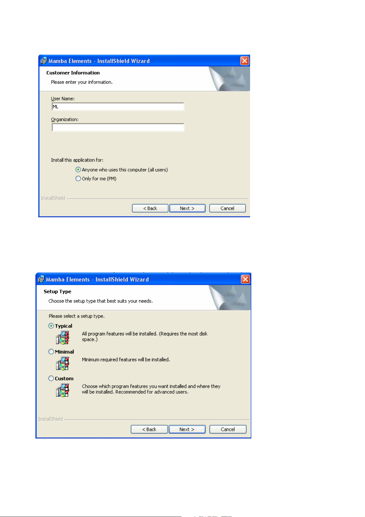
Click “next” and follow the installation guide. After you agreed to the license agreement, the
customer identification screen will pop up.
Enter your name and organization, if applicable, and confirm with “next” key.
Now select the type of the setup process. For most users, the standard setup is the best option. Here,
all relevant program files, frame files and shows are copied and installed onto your computers hard
disk. If, however, you select a custom setup, you have the following choices:
© MediaLas Laserproducts GmbH 7/50
Page 8
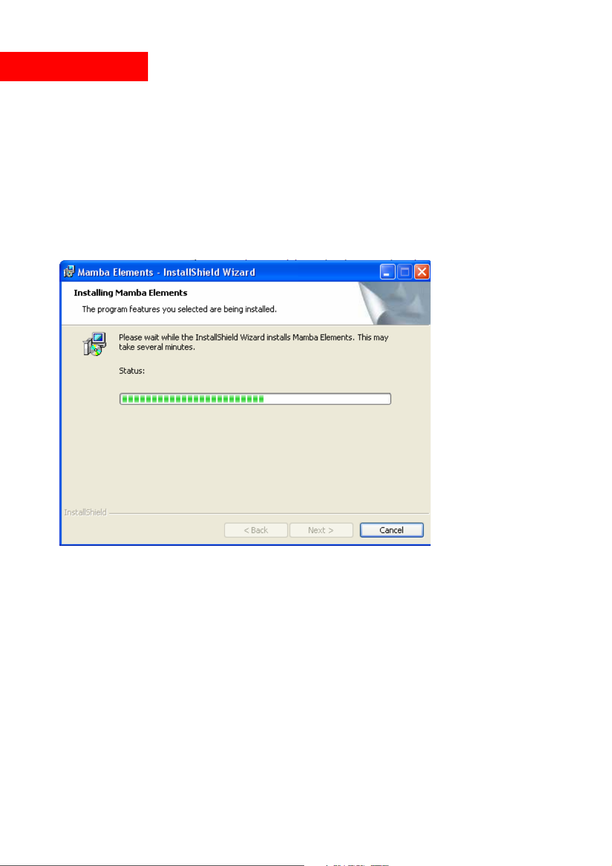
Custom setup
- Show
Installs all available free shows on the harddisk
- Frames
Installs all available free frames on the harddisk
- Manuals
Installs the actually available manuals in pdf format onto the harddisk
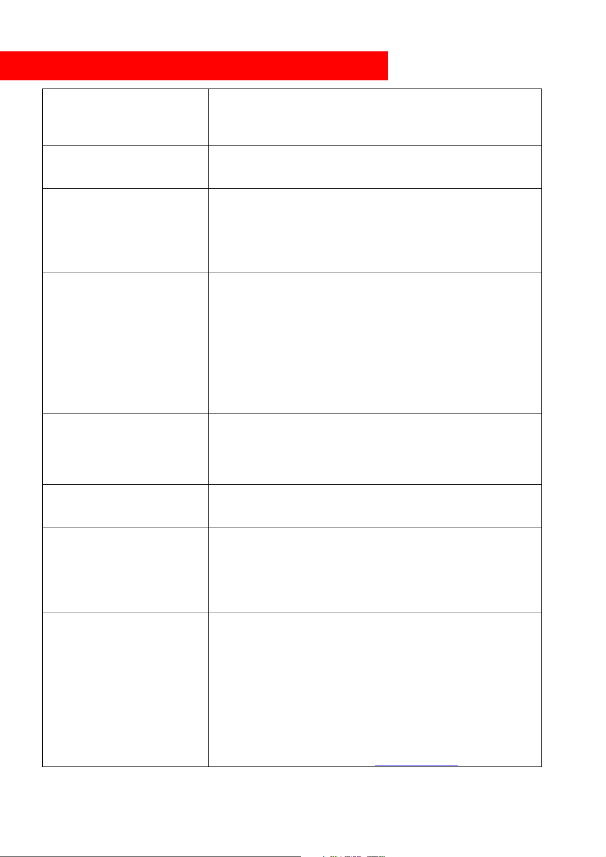
After the installation setup is finally selectn, click “next” for installation. Files are copied and
installed onto your computer´s harddisk.
After the normal software setup process, drivers for USB interface are already copied to your hard
disk. Please connect your USB interface box to the computer to finish the hardware setup. After
hardware is installed correctly, Mamba Elements is ready for first startup.
© MediaLas Laserproducts GmbH 8/50
Page 9
Glossary of laser creation and laser show programming
device, the time between point moving time and modulation time is
a beat, but can also be a start of a long animation frame at a specific
controlling device. Companies in charge of the technical committee
Beat markers
Blanking
Blankshift
Corner repeat
Cue
Mamba Elements offers a powerful programming tool, named beat
markers. During play back of a music piece, markers can be set
onto the timeline to highlight events or beat parts, to have a better
overview on the music parts.
Switching off the laser means blanking. Between two laser objects,
there must be a blanked line. If this line isn´t blanked, you will see
a connecting laser line between those objects.
Since a laser projector normally uses a mechanical deflection
system called galvo scanner, and a faster color modulation device,
usually a direct laser modulation or a crystal color modulation
different. Depending on the scanspeed, there must be a delay for
the color modulation, which is set with blankshift.
Especially on rectangle or cornered objects, just as a square, a
triangle or similar, the galvo scanner needs a specific time to reach
the reversal point, where the beam moves in a different direction.
Since this reversal process takes some time to deccelerate and
accelerate the galvo mirror, there must be a delay on these points,
which is called “corner repeat”. The corner point will be repeated
an adjustable number of times. The higher this number, the sharper
the corners, but also gets the corners brighter for the longer
projection time at this point. The optimum number must be figured
out during projection tests.
“Cues” are placed on the timeline. A cue is a scene, that can hold
single or multiple frames on the timeline, and starts at it´s desired
time where it is placed on the timeline. Usually, a cue is parallel to
Frame
Galvo / Galvanometer
ILDA format
music point.
A so called “frame” is one picture, or one drawing, in an entire list
of frames. In this frame, there is a vectorized content of lines and
dots, which shows the laser drawing during output to the laser.
A galvo, commonly called “scanner” , is the heart of a laser
projector. It is a mechanical device, which works like a fast servo
motor. It moves a mirror to a specific position. This is done usually
quite fast. The speed of a galvo for entertainment use is usually
measured in PPS (points per second), displayed with the ILDA test
pattern at a specified angle.
The International Laser Display Association developed an image
format suitable for interchanging image data between laser
controllers and laser fixtures. The information may also be stored
as frames, which can then be stored on a computer or other
of ILDA are LaserMedia, Image Engineering, Foresight, and Laser
Dream. Since ILDA's inception in the early 1990s, profit for large
laser companies, which developed the technology, have
plummeted. This may be due to the fact that the technology has
become more widespread in manufacture and affordable. More
information at ILDA´s website at
www.laserist.org
© MediaLas Laserproducts GmbH 9/50
Page 10
ILDA standard
Mamba
Interface
Interpolation
Key frame morphing
Logical projector
Modulation
Non linear cutting
ILDA developed several standards in the last couple of years. The
usual and most common ILDA standards are:
- Frame format standardized
- Scanspeed standardized to standard ILDA test pattern
- Connector standardized to DB 25 pin connector
More information about the ILDA standard is available at ILDA´s
website at www.laserist.org
An interface is a device between your PC and your laser projector.
It will convert digital signals, coming from the laser software, to
analog signals, used by most laser projectors. For an international
standard, the International Laser Display Association ILDA created
the so called ILDA Standard connector, which exactly describes the
necessary signals at the correct pin. > See ILDA standard.
Elements
works with various interfaces. The most used is the USB Box
Interface.
Interpolation is a method of adding extra laser points to a laser
projection line between it´s start and end point.. Between these two
line end points, additional points are added, to ensure the
mechanical mirror movement of the galvo runs smooth between the
two end points. This greatly reduces overshoot at corner points, and
increases the overall brightness of the inner line elements.
Interpolation distance can be set in Mamba Elements.
Morphing between frames can be done in different ways. Key
frame morphing is meant by a morph between different “key
frames”, where just these key frames are used for the morph. The
results are different to the normal morph.
Non physical projector. Mamba Elements offers logical projectors
and physical projectors in the projector setup. A logical projector
holds routings from different tracks. This logical projector can
now be routed to any physical projector. If two or more interfaces
and physical projectors are available, it might make sense to
design a logical projector, that is routed to both physical
projectors, and two logical projectors that are routed to each
individual physical projectors. During show programming on the
timeline, an effect can now be programmed to one of the three
logical projectors, which now automatically route the content to
the physical projectors. By using this powerful tool, one track can
be routed to virtually and number of physical projectors.
Modulation of a laser means, switching a laser on and off. There
are basically two ways of laser modulation: TTL On/Off or analog
from 0-100%. Depending on the quality of the laser projector, both
methods are used on the actual market. TTL modulation is mostly
used by cheap laser projectors, while analog modulation can result
in unstable laser operation, also mostly on cheap laser projectors. A
good analog linear fading modulation is only acheaved at
professional lasers. On TTL modulated RGB lasers, the color range
offers just the seven basic colors, which analog modulated lasers
can theoretically display all available colors in it´s color range,
including smooth fade ins and fade outs.
Some older laser show software programs offers linear cutting,
where the cues are listed in a text file and be played one after the
© MediaLas Laserproducts GmbH 10/50
Page 11
Object oriented editor
Furthermore, the PPS nominates the output speed, how fast a frame
ed. The faster the scanner, the less flickering you will
em and usually the power supply. A projector can be
Audience scanning
Point oriented editor
PPS (points per second)
Physical projector
Projector
Scanners
other. With a non linear cutting, you are able to access any
timeplace on the timeline at any time, you are not restricted to do
“one after the other”. If you like, you can start by creating the end
of the show before the start of the show.
Drawings are split into objects. Each drawn object, circle, line,
square, text, etc., is handled and can be edited individually at any
time.
A drawn object is recalculated to a point oriented format during
drawing. After the object is recalculated, no more changes can be
accomplished on the objects, just on single points. This makes it
hard to edit frames afterwards.
This is the speed, where galvos scanners can be compared.
can be project
notice. PPS for entertainment and lasershow is measured with the
original ILDA test pattern at a scan angle of 8° optical.
Unfortunately, many non professional companies declare their
scanners way faster than these scanners are able to work, by
manipulating the ILDA test pattern or simply using a different test
frame. For this reason, scanners can only be compared, if tested
with original ILDA test pattern at desired scan angle.
This is the “real” laser projector, a piece of hardware, scanners,
lasers and so on. See “Projector”.
The laser projector is a unit, that holds the most necessary
components for projecting laser images or a laser show – the laser,
the galvos syst
simple, or it can be sophisticated for professional use, like an
Infinity or Mystiqe.
See “Galvos”
Scanspeed
Timeline
Track
The speed, how frames, scenes or a show will be played back on
your laser projector, is measured in PPS (points per second) In
Mamba Elements, the scanspeed can be adjusted from 1,000 pps to
130,000pps. The faster the scanspeed, the less is the flickering of
the laser projection, but more scanspeed could cause more
distortion on your galvo scanners.
The timeline holds various tracks and runs from time zero to
unlimited time. Start of the timeline is exactly the start of the
desired song at time zero. Parallel to the timeline, the loaded music
piece is playing time sync.
Tracks holds cues and scenes on the timeline. Each track on the
timeline starts at time zero. Many tracks, in theory unlimited, can
be assigned, while each track starts at time zero. Cues and scenes,
which are placed on different timelines, will be played exactly at
their starting time, no matter what the contents on other tracks are.
If laserbeams from your lasershow are going into the audience.
This could be very harmful for your audience, so be sure that the
laser safety rules are observed!
© MediaLas Laserproducts GmbH 11/50
Page 12

Understanding show creation with Mamba
Mamba was designed for easiest and most convenient show design within shortest time. To
understand the principles of Mamba, here are a few explanations.
• Designing shows
A show is designed of frames (pictures), which are set on a timeline with linear and absolute
timings, and are either just played back or manipulated and animated with various effects. The
timeline shows the absolute time from point zero until – in theory – unlimited time. Each second on
the timeline is divided into 25 frames, which allows to have up to 25 cues per second, and up to
1,500 cues per minute. A show of 4 minute length can held up to 6,000 cues. Each cue can store one
or more frames. The number of frames per cue, is dependend of the cue length, the frame content
(how many point are in the frame) and the scanspeed. Here is an example:
Your frame (picture) holds 200 points, which is not much. Some frames can hold up to
5,000 points, which, on the contrary, IS much. A normal frame content could be something
around 500 – 1,500 points. But for now, we assume, that your frame has 200 points. At the
same time, your scanspeed is adjusted to 20,000 points per second. We divide now the
number of points, which are outputted to galvo scan system, by the number of points each
frame contains, and we will get the repeatability rate of the projection system. In our case:
20,000 points per second / 200 points = 100 frames per second.
The picture we designed, will be repeated 100 times within one second of time.
Since we learned, that the Mamba timeline can hold up to 25 cues per second, we divide our
100 frames per second with 25 cues:
100 frames per second / 25 cues per second = 4 frames per cue
So each one of the 25 cues will play 4 frames.
The more points a frame contains, the less often it can be played back within one cue.
Note:
A cue is an absolute moment on the timeline, which is repeated 25 times per second.
On the timeline, scenes are designed with editable start and end time. Each scene can hold a various
number of frames, from one single frame to unlimited number of frames, which will be played and
shown on the laser output within this scene`s start and end time. Many scenes can be chained on the
timeline and will be played back at the desired time frame, shown on the timeline.
Talking about scenes – a scene in Mamba is a very powerful object to bring your ideas into lasers.
In a scene, you can do much more than “just” project a frame or a frame list. Animate, rotate. zoom
or move them, morph them, set the scene to a scrolling text or display the current time – it is that
easy!
On the main screen of Mamba you see the absolute time your show is running at. This timeline is
100% parallel to your music timing. Once you selected a song, the timeline will show you exactly
the time of your song with 25 cues per second.
© MediaLas Laserproducts GmbH 12/50
Page 13

The scenes you create on the timeline will play exactly the time where they set to – start and end
time. The start and end time of each scene is free adjustable with your pointing device, and can be
moved everywhere on your timeline, even between different tracks. Simply drag and drop them
around.
An entire show is made of various scenes, which can hold single frames, frame lists, running text,
realtime clock display or a pause. Many scenes lead up to an entire show, while a good and well
timed show can easily hold a few thousand scenes as single cues! Sometimes less is more, and
sometimes a show lives from cues. This depends not just on your taste, but also on the artists
attitude, or music style. Mamba comes with a large number of different shows in different styles.
Simply load a show and enjoy it while watching the artists expressions. After you have seen the
show, scroll through the timeline and check out how this show was created with the various tools
and effect modules. It might be confusing for the first time, but once you got the feeling for Mamba
(which usually happens pretty fast), your mind will flow and shows come by some simple clicks.
You will be delighted, how fast a show is created in Mamba, with professional look and amazing
effects.
Adaptive graphical user interface
What do these guys wanna tell me? A user interface that adapts to what? Well, the time when we
designed Mamba, we have already been experienced lasershow artists, who worked with different
kind of software programs, and knew about pros and cons of existing systems. While every
software system has it´s advantages, we where thinking about Mamba being the “easy part” of the
laser scene - a software, able to run on notebook computers, no need for expensive interfaces, easy
to use and fast to learn. This required to have only one main user interface on the computer monitor,
other than having many different programs with various windows on the desktop. So we decided to
design a variable, adaptive user interface, which basically looks the same all the time, but offers
different tools and content to the user, depending on the workspace he requires.
While Mamba in the upper part of the main window, constantly shows the most important
information, frames and previews, the lower part of the main interface changes in it´s content to fit
Mamba to the operators actions. After a few hours of use, you most probably will not miss this
tremendous feature anymore.
© MediaLas Laserproducts GmbH 13/50
Page 14
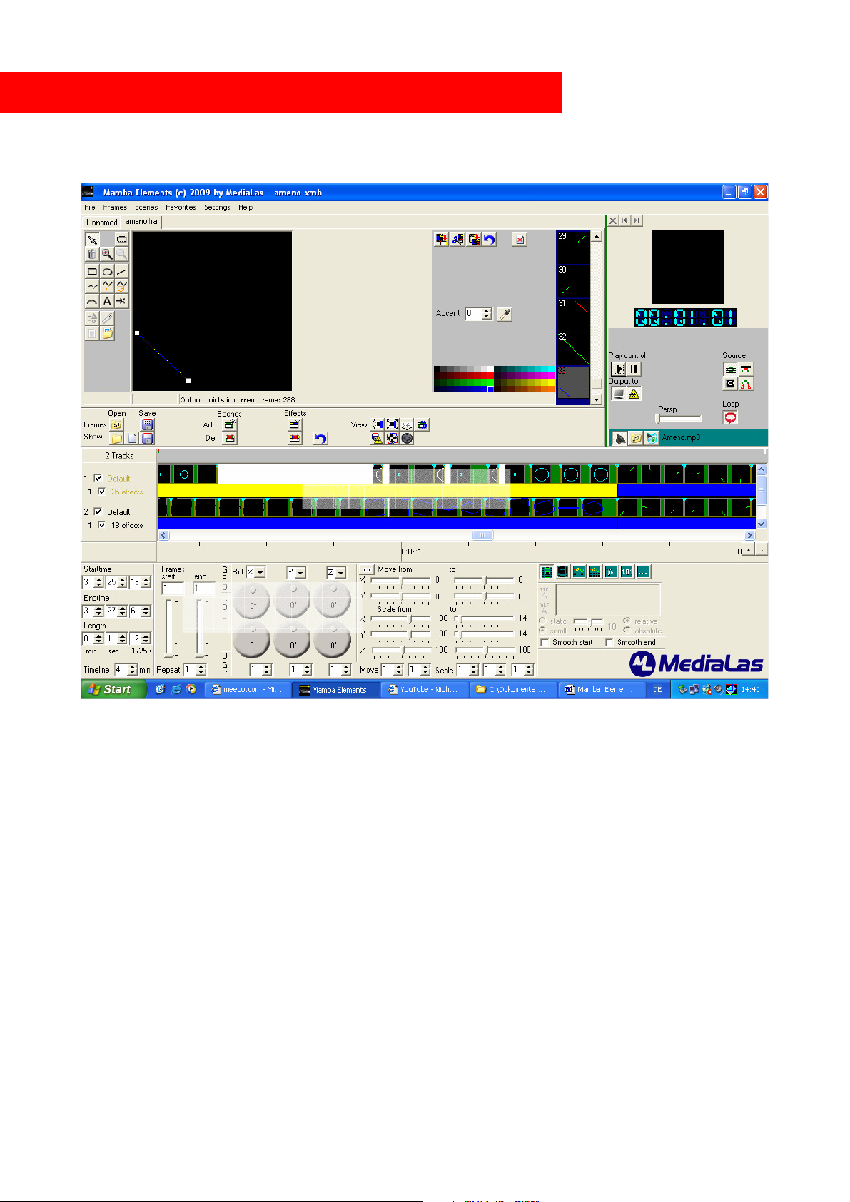
Introducing Mamba Elements Main Screen User Interface
The 4 major parts of Mamba Elements:
Editor /
Framelists
Timeline
Laser
Preview
Scene/Effects
Basically, the main Mamba Elements screen is divided into 4 major sections, which will be
described separately in this manual:
1. Editor for frames and framelists
2. The Timeline, that holds the animation tracks
3. The Scene/Effect panel
4. The Laser Preview with output and play control
All 4 parts are set onto one interface screen, which allows to oversee all necessary information at
once. However, the screen can be set to different width and variances, just as increased timeline
window, increased laser preview window, increased editor window etc. To move or change
dimensions of screen parts, just click, hold and move the mouse pointer to separator lines on the
screen.
© MediaLas Laserproducts GmbH 14/50
Page 15
Editor/Framelists
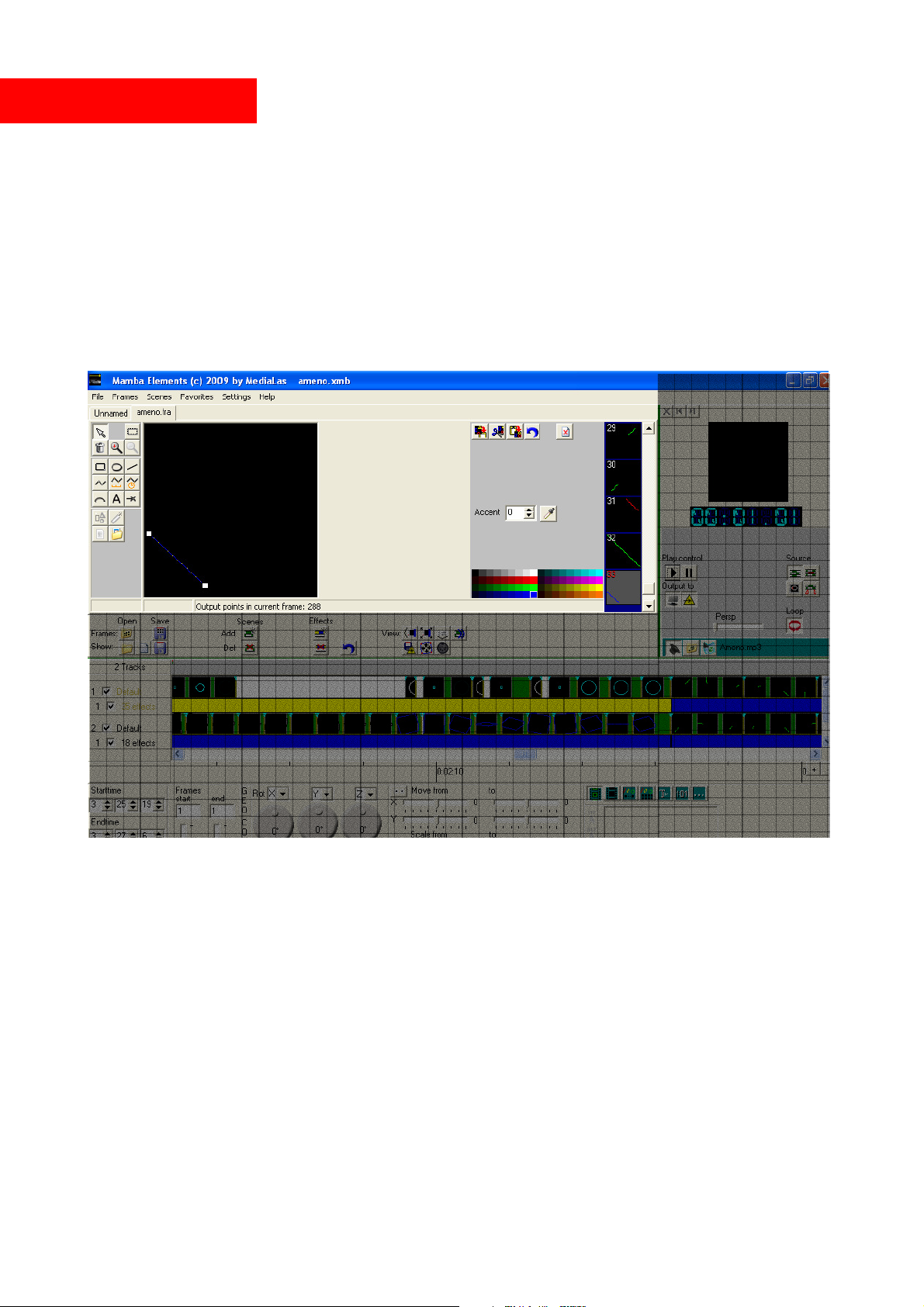
The frame and drawing editor of Mamba Elements is a bit different, compared to other kind of laser
software. The main difference is the handling of the drawn figures, the “objects”. Each single object
is handled individually, you are not restricted by single points or areas. Even texts can be edited at
any time and changed or manipulated easily at any time during, before or after the show. Therefore,
we call Mamba Elements “fully object oriented”.
Logos can be traced by loading a background bmp image, and following the outer lines with the
polyline tool. To avoid any image distortion on the bmp image, we recommend to hold the bmp
image in an exact square shape. Use a simple painting tool to create a square picture, and insert your
desired logo or bitmap, that you wanted to use as background.
The editor holds an unlimited number of framelists. The left, large window shows a selected frame
with all corner points and colors, the overview list next to the Laser Preview window offers a
scrollbar to scroll through the framelist for easy and fast access, and additionally acts as an
overview. By double clicking on a preview frame in this list, the frame will be opened in the editor
window for editing, recoloring etc.
Each frame in this overview window can be dragged and dropped onto the timeline into scenes or to
create new scenes.
By clicking onto one of these frames with the right mouse button, a menu will open, which lets you
add, copy, paste or delete frames from this list.
Create a new frame
Either use the drop down menu “Frames” or the right mouse button in the overview window, select
“New frame” and confirm. A new frame is added to the list, but it is not yet active in the editor
© MediaLas Laserproducts GmbH 15/50
Page 16
window. Now double click on this new frame in the overview window, and it will appear in the
editor´s window.
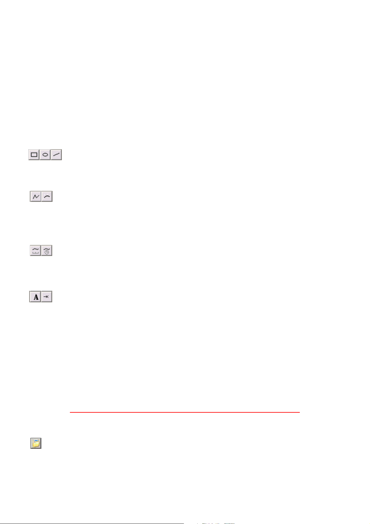
The tools
The editor of Mamba Elements offers various tools to create and draw images, logos, cartoons or
text, for later use on the timeline in the showeditor. To select a tool, simply click on the tool button.
If you want to work continously with the same tool, simply hold down the shift key while clicking
the tool button. It is then locked until you select another tool. If you simply click on the tool
buttons, the buttons will stay for one drawing movement, and then release to their off position. To
activate a drawing tool permanently, hold down Shift-key while clicking on the tool button. Now
you can use this tool until you select other tools or press other buttons or hit the ESC key.
Rectangle, ellipse, line click to activate. Use the mouse pointer to draw shapes in the
editors window. Click and hold the left mouse button to draw the figure, after releasing
the mouse button, the drawing will be finalized and is now available in the editor window as a new
object.
Polyline, Bspline left click for each point, right click to set last point.
Polyline is a very powerful tool, and is mostly used to trace lines or outlines from a
background bitmap image. Also, the polyline tool lets you draw closed objects with no blanking
lines. By left clicking, a new corner point is set. For finishing drawing with the polyline tool, simply
right click.
Free hand press left mouse button and drag. Press the ctrl key to round the current
coordinates to multiples of 100. The gap between the points can be adjusted in the settings
menu, see Settings.
When finished drawing, the object is active and the tool “Select” is activated.
Text, beam click on the canvas to position.Select the text tool. Now hit desired position on
the drawing window, and the text box right to the drawing window will open. The toolbox
will allow you to select the desired font and to enter some text into the text line. This text will
immediately appear in the editor window. It behaves like all other tools, and acts as an object,
which can be moved, resized or recolored at any time. Text objects can also be changed at any time,
even during a show.
The beam tool is very powerful for setting single or multiple beams onto mirrors or simply in the
air. Each beam consists of one single point, which is repeated a specific time. By default, it is
repeated 40 times. How many times each point is repeated is shown in the accent box right to the
editor window. (Refer to the Accentuation section later in the manual) A beam can be moved or
recolored at any time.
Warning! Single static beams can be very harmful, if aimed to audience!
Background images
Mamba Elements offers very powerful tools in combination with background images. You can
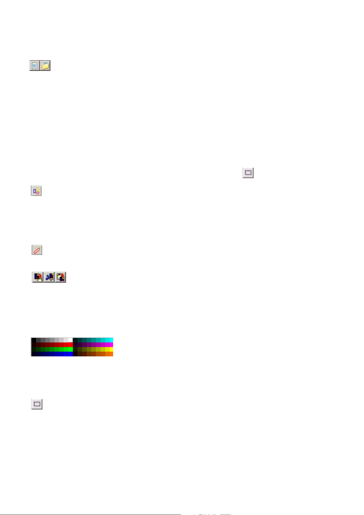
load a background image by clicking on the button. This is useful when creating logos. All
bitmap files will be loaded. Be careful! Mamba Elements will stretch bmp files to a square format.
If your file is not square, it will be stretched in one direction. So be sure to prepare bmp files in a
© MediaLas Laserproducts GmbH 16/50
Page 17
square pixel format, just as 300x300 or 400x400 pixels. The most simple way is to use the Paint
program from MS Windows.
Turn the background image on/off. The images will not be projected in lasers, they are
simply used as a background image for tracing or drawing logos and/or figures. With this
button, you can switch the background bmp image on and off, to either see your tracing results or to
switch off the image after finishing your frame.
Selecting drawn objects
Click on, or close to, any object (at a corner point or the lines in between) to select objects. You can
drag and move any object to another place, or change the shape by dragging the markers on the
corner points.
When you hold down the alt key while selecting an object you can change the size of the object.
To select/unselect multiple objects hold down the ctrl-key or use the region button.
You can group objects with the “group objects” button. To select/unselect multiple objects hold
down the ctrl-key and click the objects you want to select for a group. After selection, press the
“group” button. Your selected objects will now be grouped. Now, these group can be manipulated
with other tools, such as move, resize etc.
But even within a group, a single object can be selected. To select a single object within a group
hold down the shift key while clicking.
Ungroup with the “ungroup objects” button. First select the group, that has to be ungrouped,
and press the “ungroup” button.
Copy/cut/paste objects with the buttons above the layer list. All marked or grouped
objects are copied or cutted out with a mouse click, and re pasted the same way.
Selecting a text object allows to edit text, or change the font or letter size at any time. The changes
will be affected immediately within a show.
Adding colors to your laser show
Re-color selected objects by clicking a color on the color pick.
The color in the top left corner is black, which is good for changing
colored objects (or parts of them) black, which results in blanked lines.
Double click to change a color. You can save / load a palette from the local menu (right mouse
button) of the color pick area.
The selected color stays active, new objects will be drawn in the active color.
If you want to color only parts of the frame use the “Select rectangle” tool to select a
rectangular region, and then click on a color.
Another very powerful recoloring tool is the “recolor from background” tool, available with your
right mouse key in the effect editor. You can use background images to recolor objetcs. In the
folder “colors” of the program folder you will find example background images, created with
CorelDraw drawing software. When the background image is loaded, select “Recolor from
background” from the local menu (right mouse button) of the editor area. If no selection is active all
© MediaLas Laserproducts GmbH 17/50
Page 18
objects will be recolored. You can select objects and/or regions, to recolor the selected
objects/regions only. All non selected objects or regions will stay on the default color.
Example:
Draw a simple square in white color. Now open a background color image with
“open background”. Select a background bitmap file from the “colors” folder in your Mamba
Elements directory. Select the rectangle, click the right mouse button and select “recolor from
background”.
Colored bitmaps can be imported and created at any time, using various software programs on the
market. Please make sure, that the final bmp file has a squared shape with similar number of points
for both sides. Open the colored botmap same way as opening background images. Now right click
on the object, and select “recolor from background”. After finishing, just turn the background image
off.
Accentuation
Accents are another very powerful tool for making your lasershow brighter and adjust objects to
different scanspeeds. It has to be used carefully interms of laser safety, to avoid high power beams
into the audience during audience scanning.
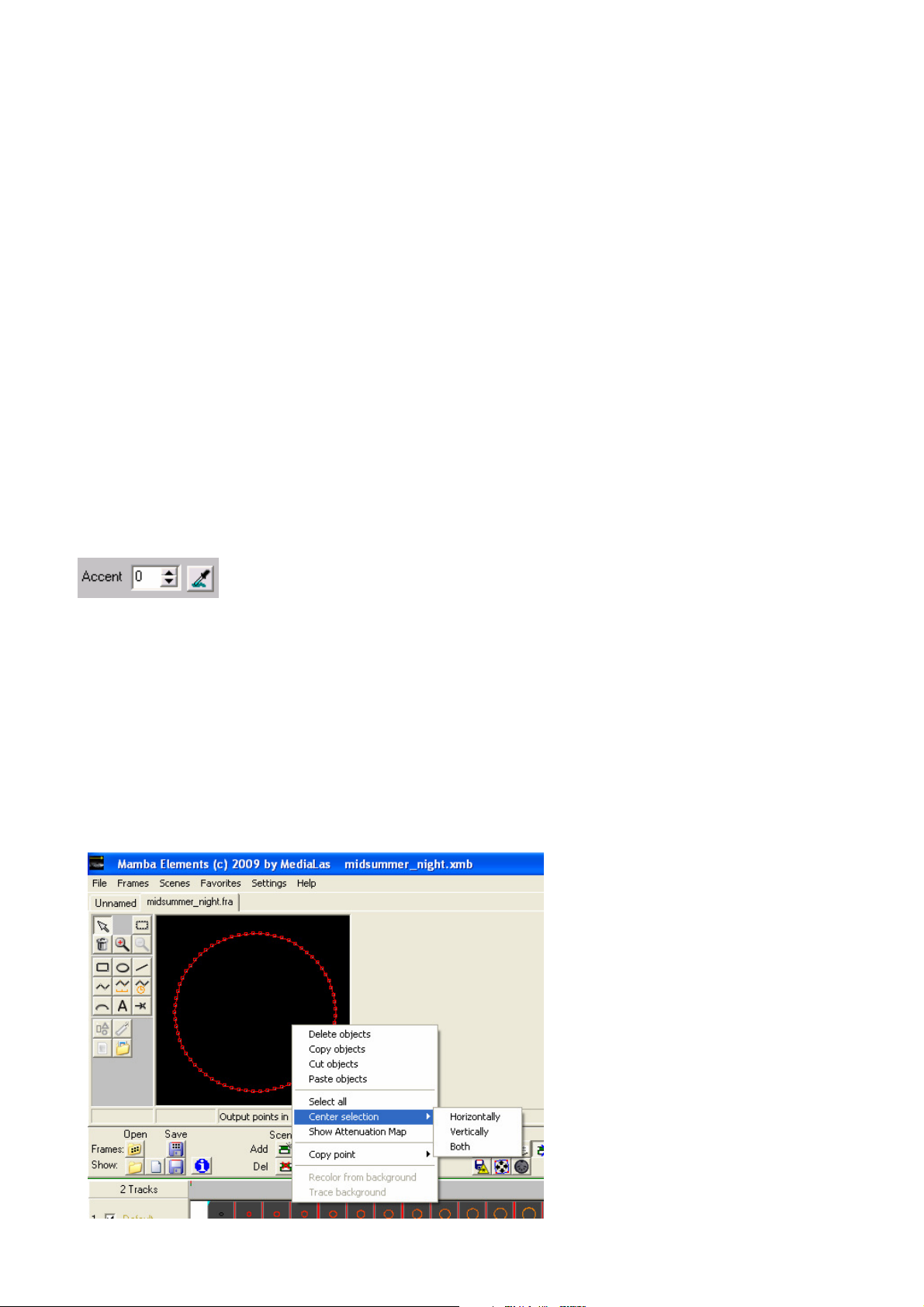
Select an object and change the value to increase the brightness of line points in
an object. Press the “pick color” button, then a color on the color pick (see
above) to change the color of these points. Tip: select an accentuation color, and then change the
object to black if you want to show only the intermediate points.
Changing the accentuation of beams will increase the time, the beam is displayed within dots on the
shape, it will then appear brighter. At the same time, it decreases the frame repeat speed. In large
frames, a non wanted flicker can occur. But sometimes, this is wanted and results in some nice
artistic effects.
To learn more about this powerful tool, simply draw some different shapes, just as a rectangle or circle, and play around
with the accent tool during laser output.
Auto centering objects
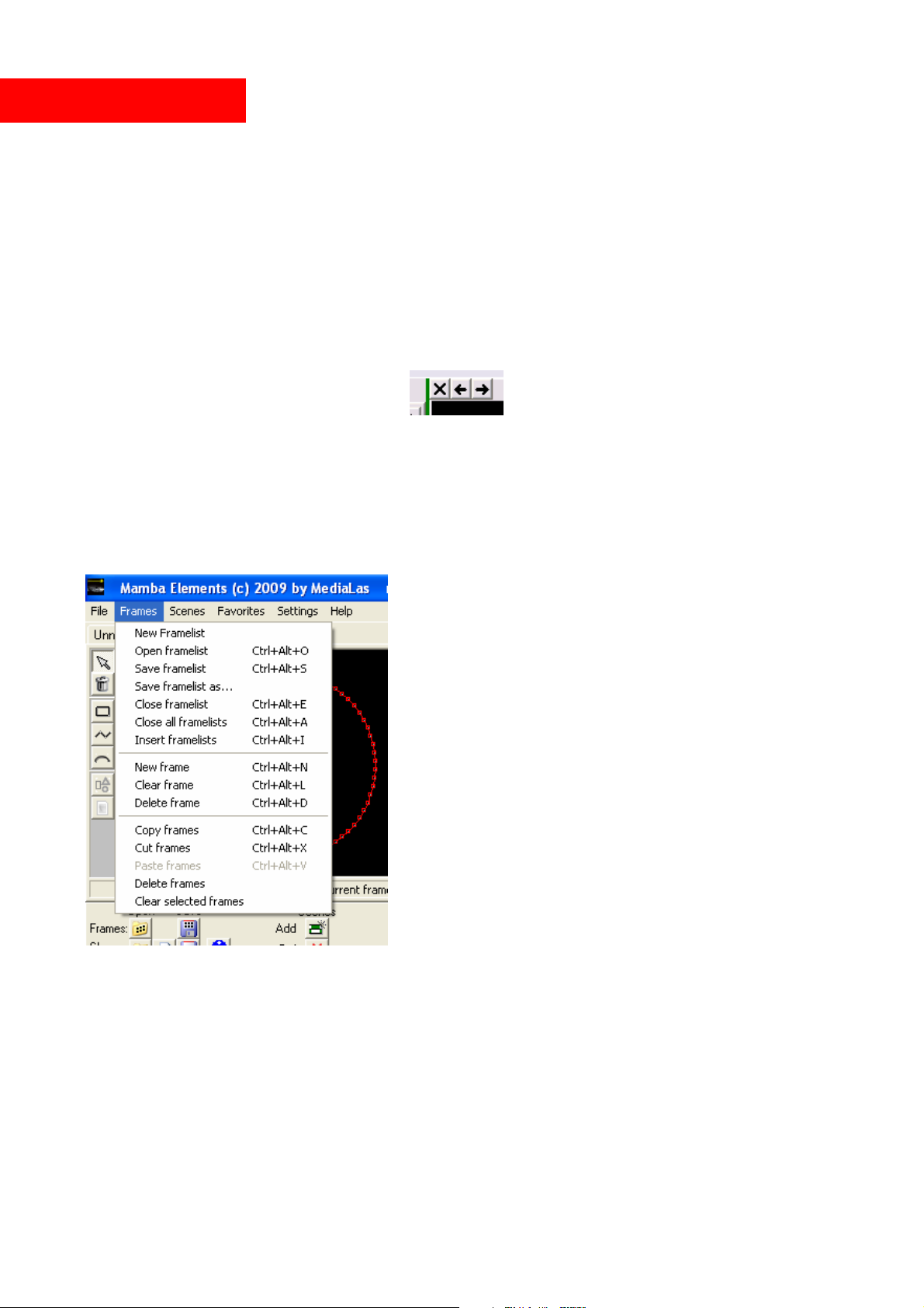
You can center selected objects by
choosing “Center objects” from the
local menu, or simply click on the
object with the right mouse button to
open the dialog. Here, various
centering processes can be initiated,
such as centering horizontally,
vertically, or both.
“Copy point” from the local menu
annotates a point from the selected
objects or the current location for
later use in the show editor, for
example as rotation centers.
Single objects can be duplicated,
removed, cutted out, or pasted in.
© MediaLas Laserproducts GmbH 18/50
Page 19
The frame area
Edit framelists
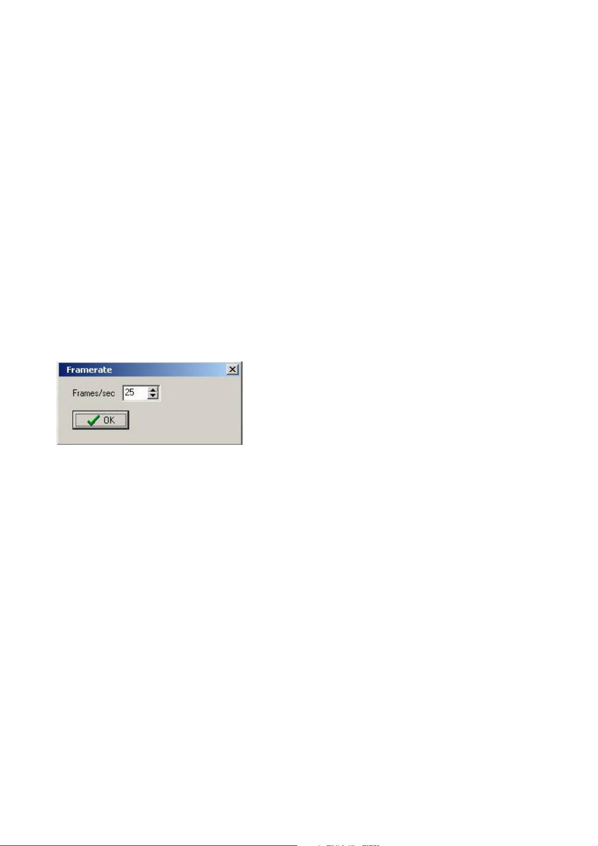
The frame area shows all the frames in the current frame list. Right click on a frame, or use the
menu, to add/delete/clear frames or open/save frame lists.
Double click on a frame to open it in the editor.
You can copy/paste frames between framelists. To select the frames click on the start frame, then
hold shift and click on the end frame, the selected frames are marked with red frame numbers. To
copy/paste click the right mouse button.
Use Ctrl+Tab and Shift+Ctrl+Tab to move to the next/previous frame list. Ctrl+F4 closes the
current framelist.
Close/scroll through frame lists using the buttons above the preview window. Be
careful with the cross button – this one deletes the actual open framelist from the
list tabs!
Adding frame lists: you can add a frame list into an open frame list from the local menu (“Insert
framelists”), and additionally from the drop down menu box. From the local menu you can also
close all open frame lists.
Saving or loading framelists
It is very important to save edited framelists after final
editing, and from time to time during editing or frame
creation, to avoid any data loss after sudden software
instabilities. To save a framelist, or multiple framelists,
simply open the dialog menu from the top menu list. Here
you will also find the latest accessed framelists.
Please note: Saving just the framelist does not mean, you
also saved the show file! If a show was created before,
also save the show by dropping down the file menu.
Object frames – this is the Mamba Elements internal standard file, which saves frames as object
oriented frames.
Just behind the menu points, you will find the direct key access codes to these functions.
Experienced artists and programmers will find it very useful to use the key codes instead of
dropdown menus.
© MediaLas Laserproducts GmbH 19/50
Page 20
Import ILDA framelists
Note: You only can improt ILDA framelists with max. 250 frames! In case of the framelist has
more than 250 frames, the other frames will be cutted and will not load!
ILDA standard framelists can be imported in two different ways:
- Open frame file in the “Frames” menu as a framelist
If a regular .ild framelist is opened or loaded with the “Open framelist” command, all frames are
available in a regular framelist, and can be used like normal frames within a show. Frames have to
be moved or dragged to the timeline, and there has to be a scene or show created. This is usually
done, if a framelist contains different frames, which does not relate to each other, just as a ongoing
comic etc. Also, this mode is used for opening single ILDA frames.
- Open framefile in the “File” menu “Show from framelist”
If a continous framefile is available, Mamba Elements can automatically create a show out of this
frame file. Example could be to export an entire show to an ILDA frame file, with a fixed frame
rate of 50 fps, and the import to Mamba Elements. Any timing, that has been done on the show, will
also be available in Mamba Elements.
After the appropriate file is selected, Mamba Elements asks for the frame rate. If a show was
exported with a specific frame rate, enter the correct value to make sure, the original timing of the
show is reproduced.
© MediaLas Laserproducts GmbH 20/50
Page 21
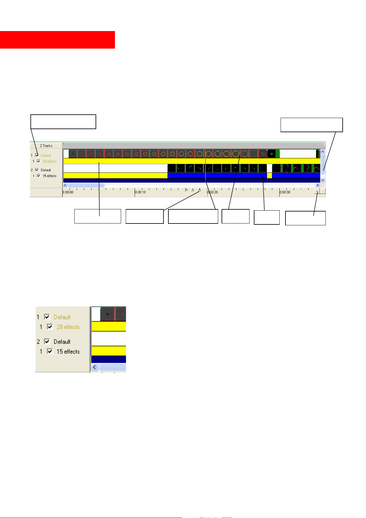
Timeline/Show editor
The show editor is located below the frame editor window. A show is basically a collection of
various scenes. In Mamba Elements, the number of scenes on the timeline is not limited. After a
scene is placed, it can be moved and changed at any time. What happens in a scene is also displayed
on the timeline in the frame previews. Any change that is made during creation, is immediately
displayed in the scene content pictures. Movements, animations, rotations, zooms etc are done in
the scene directly, there is no need to create a separate effect to move a frame.
Select/Unselect track
Scroll through tracks
Effect Track
Beatmarks
Ruler/Timecode
Scene
Effect
Zoom in/out
Tracks
On start up you will see 2 tracks on the timeline in white color. This color can be changed in the
setup menues. However, we recommend to leave it in the preset colors for user compatibility.
To select a track click on the name to the left of it The text of the selected track will be displayed
on white background. All actions will now affect this selected track.
The checkbox to the left controls visibility of the track during laser and screen output, uncheck to
temporarily disable the track. This could be necessary during programming or on special
presentations. By selecting tracks, various laser projections and images can be displayed within the
same show at the same time.
Each track holds 1 subtrack, so called “Effect tracks”, which are displayed in yellow color below
the selected main track. Additional effects on this sub tracks control more movements and increases
the freedom of artistic use. Effect tracks uses processor power, so depending on your computer´s
processor speed, effect tracks could effect the projection speed.
© MediaLas Laserproducts GmbH 21/50
Page 22
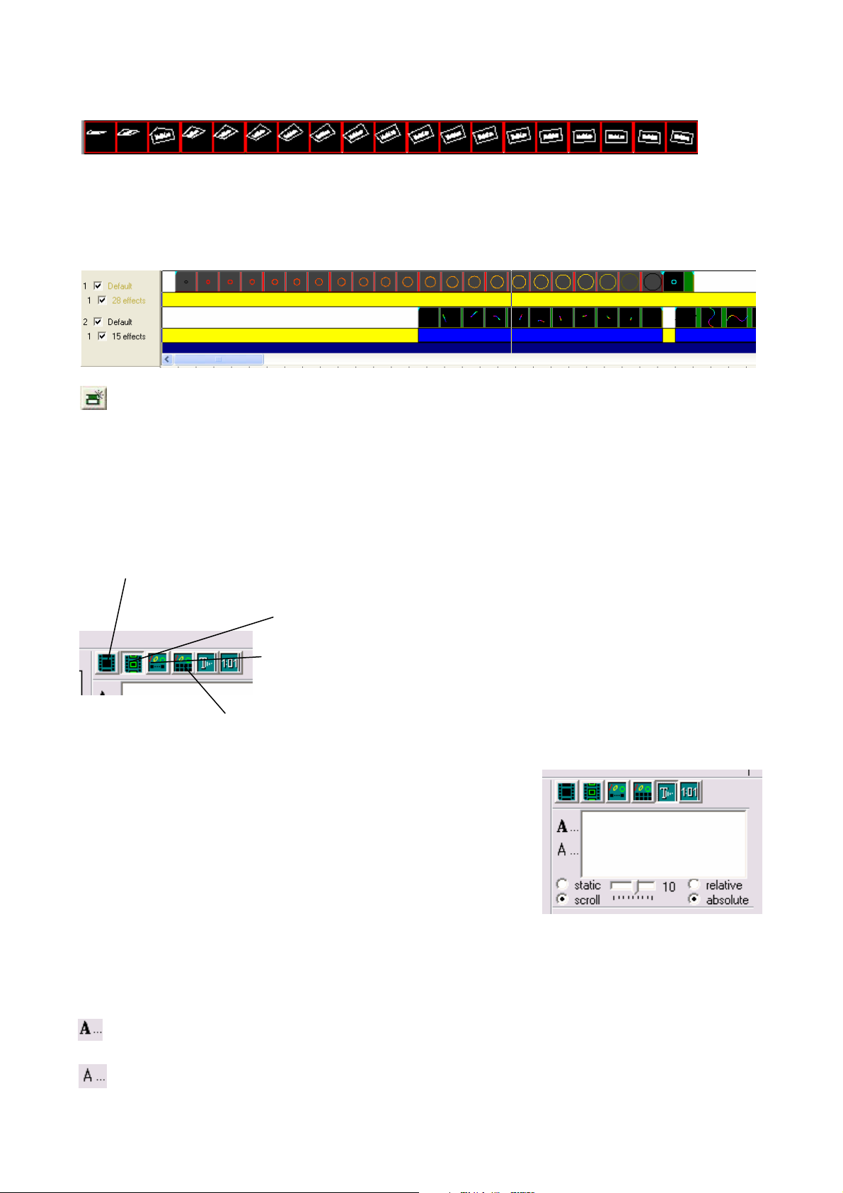
Scenes
Each track on the timeline uses one scene track, while unlimited number of scenes can be placed on
this track. A scene can hold a various number of frames from any opened framelist, or is capable of
displaying the computer time, morph or pause or display a static or scrolling text.
Scenes can be added onto tracks, which are displayed on the timeline:
To add a scene to the timeline either the “Add scene” button is used or simply drag and drop a
frame from the framelist onto the timeline to create a new scene with 1 second default play length.
This default length can be changed at any time from 1 cue (1/25s) up to unlimited length. The frame
will then automatically become the start frame of that scene. If the scene is created with the “Add
scene” button, it will be added on the leftmost empty spot of the selected track and will be 1 second
long.
The buttons on the bottom right lets you select the type of scene:
Pause: nothing will be displayed. Use this to temporarily disable a scene or show no laser
output during the regular show.
Play frames: the scene will display the frames sequentially from start
to end value.
Morph start to end: the scene will morph the start frame to end frame,
ignoring all frames in between (in case the frames you want to morph
are not consecutive in your frame list).
Morph all frames: the scene will morph each two consecutive frames, from
start to end value.
See “Frame area” above on how to add frames to scenes.
Text: A nice feature of Mamba Elements is the ability to run a
simple scrolling text on the timeline, whithout programming
frames before. You can enter text in the text area below the
buttons and select whether the text should be scrolling or static.
For scrolling text you can adjust the speed with the slider either
relative to the scene’s length (a value of 10 means once from
right to left, -20 2 times from left to right, etc.), or absolute (so if
you change the length of the scene the scrolling speed won’t change). For static text the slider will
change the horizontal position of the text.
To change fonts, click
(for TrueType fonts) or
for simple fonts. These fonts are mainly used, if a high letter quantity is necessary, but font
quality is not that important.
© MediaLas Laserproducts GmbH 22/50
Page 23

Clock: Displays the current real time of the internal computer clock. The time will be displayed, as
long as the scene is running on the track. Create a new empty scene, then press the Clock button,
and the laser will display the real time laser clock.
Each scene has a position and length on the track, which is shown on the lower
left of the screen. Adjust the values with the spin edits, or drag the scene or its
borders to the desired values. Holding the Ctrl key while dragging a scene or its
start/end will snap the values to the tick marks.
To select a scene simply click on it. Select/deselect multiple scenes with
ctrl+click. You can also use “Select scenes” from the local menu (right mouse
button) together with the begin/end markers to select a range of scenes on the
currently active tracks.
To save the selected scenes into a separate show file use save scenes from the
local menu. You can also add an existing show from there.
Adding frames to your show
Drag a frame to a scene/track to include the frame in the current show. To add
multiple frames, or an entire frame list, add one as described before, then adjust
the frames start/end value of the scene to the desired values. As an alternative, you
can select a sequence of frames with the Shift button, and drag the whole sequence
to a scene or an empty part of a track. The frames that are currently used in the
selected scene, are marked with a red frame in the frame list. Change the repeat
value, if you want to repeat the frame sequence more thán once within that scene.
Frames are saved in the .FRA format. This format saves the object information.
You can also save in ILDA (.ild) or MediaLas’ older frame formats (.FL*). The object information
will then be lost; the frames are saved as an (unstructured) list of points. Use this option to export to
other editors or for playback (on MediaLas’ Avatar or Hotboard devices).
© MediaLas Laserproducts GmbH 23/50
Page 24
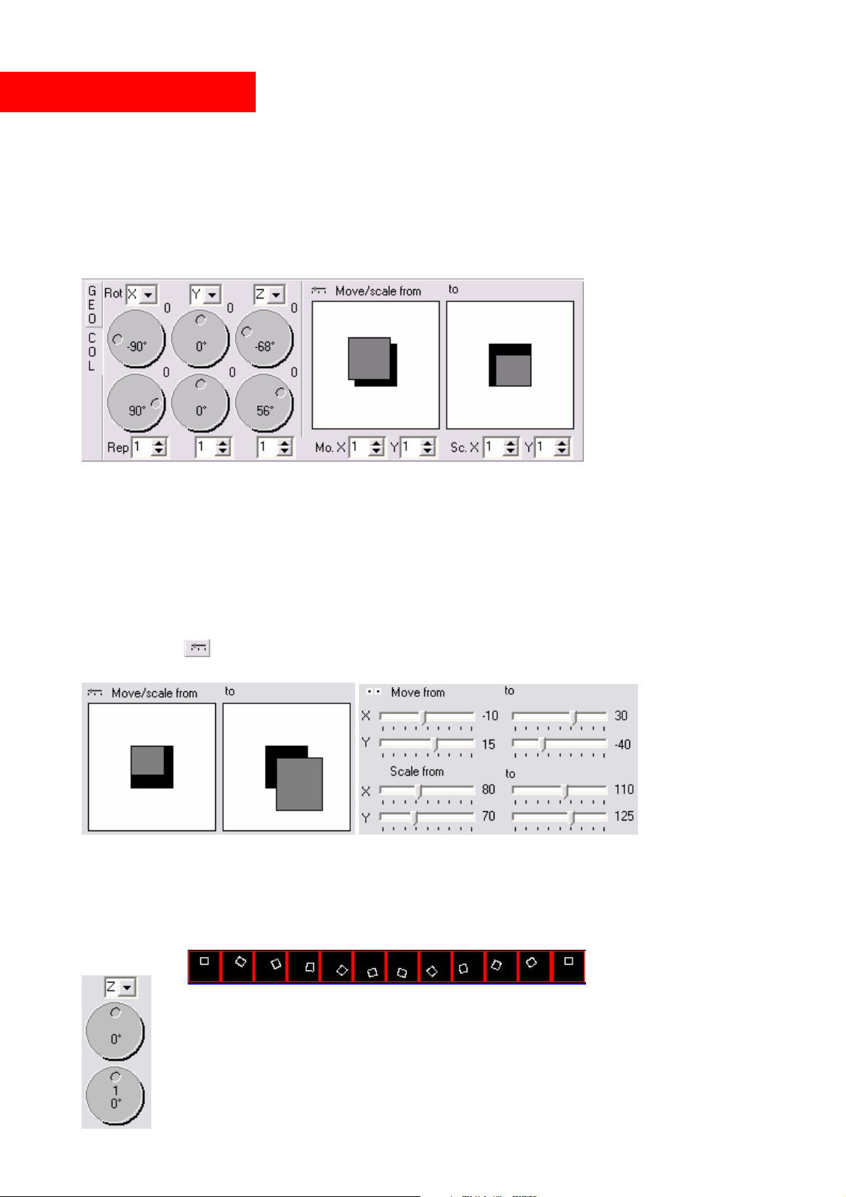
Scene/Effects panel
Now here comes the real deal. You are now about to enter the most powerful tool of Mamba
Elements.
The content of each scene can be manipulated by assigning effects. The effect editor appears
underneath the timeline when a scene is selected.
The tab labelled GEO contains adjustments for rotations, size, and position of the scene, each with a
start and end value. The scene content will smoothly change from start to end value over its
duration.
To lock start/end value while changing, hold shift key while changing the start value. To repeat the
effect more than once adjust the “Rep” spin edit next to that value pair.
Double clicking the rotation handles sets the value to 90, 180, 270, 360 degrees if the value was 0,
90, 180, 270 degrees respectively, and to 0 otherwise. Holding the Ctrl key when changing will
round the values to multiples of 5 degrees.
Double clicking the move/size areas will rest the size to 100/100% if it was changed, otherwise the
position will be set to center.
Click on the Button to change Move/scale controls to sliders, as in the image below
Double clicking the sliders (in the lower part, where the tick marks are) will reset the values.
Rotations
The following example uses a small rectangle in the upper half of the frame.
Let’s add a full rotation about z. The scene will the look as following:
The rotation is done in the center of the entire area. One full rotation on the rotation
handle will do one full rotation in the timeline in the selected scene. Simply click and
hold the button on the handle, and rotate it. Each single click onto a handle rotates the
handle at 90°. For a full rotation, click 4 times, and you get a full 360° rotation.
© MediaLas Laserproducts GmbH 24/50
Page 25
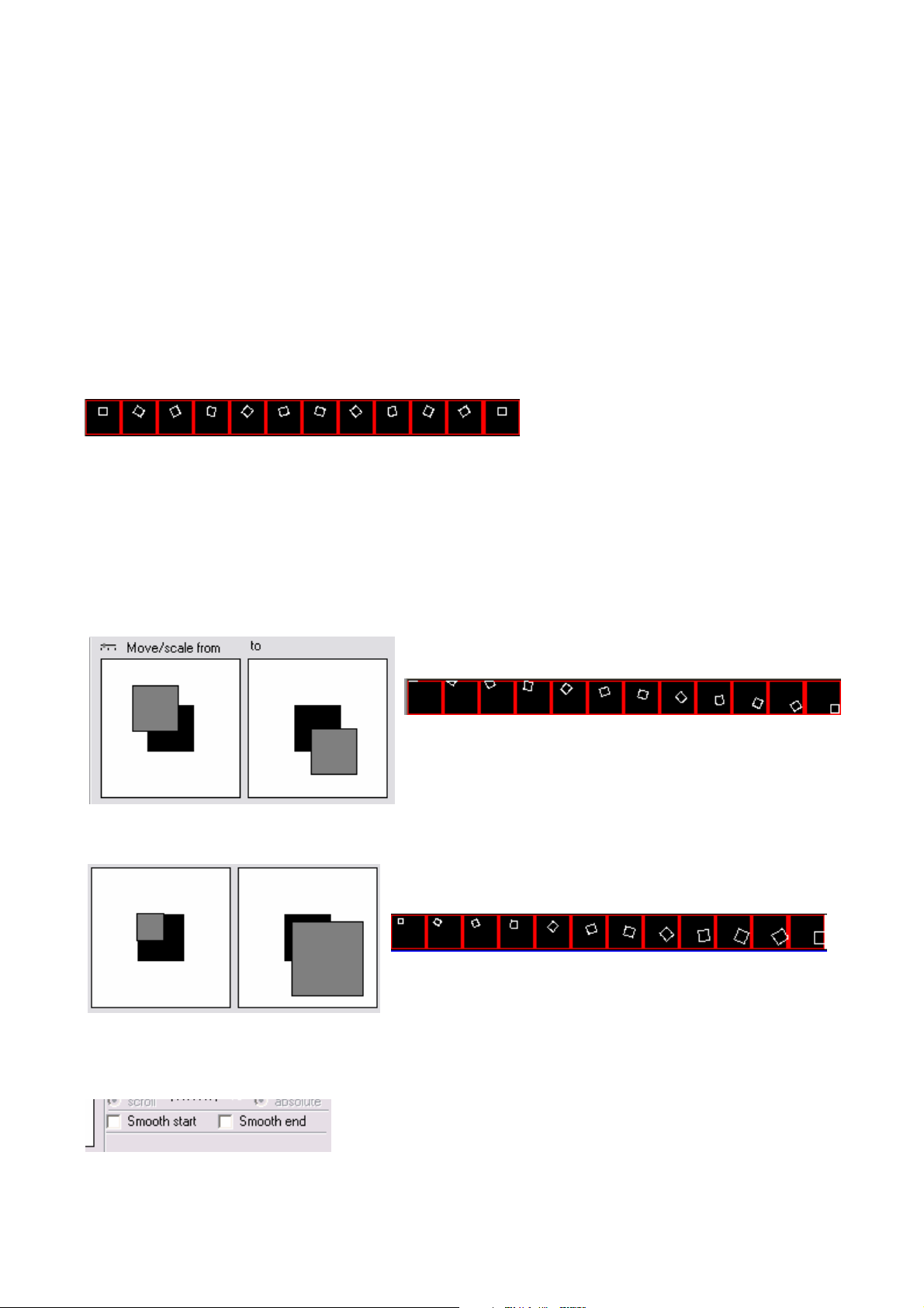
The first handle shows you the start value of the rotation, the second handle the end value.
Furthermore, the numbers in the handles show you the number of full 360° rotations, that will be
performed in the scene. If you read 1, and additionally 0°, you get one full rotation.
If the start position of the rotation should be changed, rotate the first handle for the rotation start
position, then rotate the second handle for the rotation end position.
If an object should be rotated to a static position, move both handles to the same value.
To change the centre of the rotation itself, you can right click on the rotation handle. From the menu
select ”center from selection”. This allows you to change the rotation centre to the corner points or
the centre of the currently selected object(s) in the editor window. So, select the rectangle in the
editor and use “center” from the local menu of the rotation handle. Now, the center of the selected
onject is used as the rotation center. The object will not rotate about the center of the projection
area, it rotates about itself. The scene will look like this:
Position/Size
To move the frames from one point to another, you simply drag the grey areas in the Move/Scale
area. Just place the mouse cursor onto on of the areas, click on it, and move it to any position within
the entire projection space. For example, to move the frame (the one we have rotated in the example
before) from top left to bottom right, move the start area to top left, and the end area to bottom
right. The movement is now done over the entire scene from start to end value.
If you drag the border of the grey areas you can change the size of the frame:
For a static repositioning of an object, simply move both areas to the same coordinates. Hold the
Shift button to lock both start and end value, then move the areas with your mouse pointer to it´s
desired position.
You can accelerate/decelerate the effect speed at the
beginning/end of a scene by checking the appropriate boxes.
These values are relative within a scene.
© MediaLas Laserproducts GmbH 25/50
Page 26
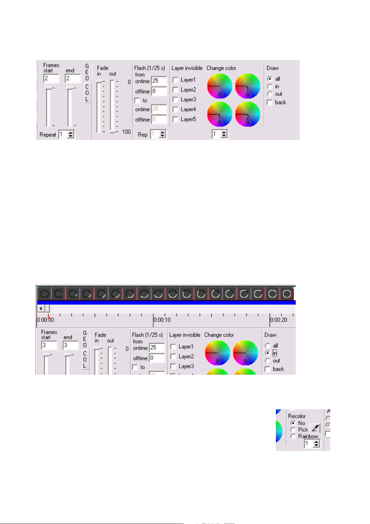
Color/intensity effects
The tab labelled “COL” selects color and intensity effects for the selected scene. Use the Fade
in/out sliders to fade in/out the scene from/to black. The sliders show the relative percentage of the
scene length. Add a flashing by entering the desired on and of time, values of 25/25 give one
second on and one second off. Check “To” to change flashing speed, values of 0/25 and 25/0 will
start with a black scene, then increase flashing until the scene is permanently on.
Check layers that you want to disable in the scene. If you designed frames in the frame editor under
different layers, now is the time to use them.
With the color morpher, you can select a color range that is morphed into a new color range. The
settings in the image below select the whole range (second dial is turned one time), to be morphed
once around the color circle (the lower two dials are turned one and two times repsectively). Tip:
You can select this setting (one complete morph) from the local menu (right mouse button) of the
dials. Also set the dials to zero from the local menu. Holding down the shift key and rotate the left
dial, will let the right dial rotate simultaneously.
Draw in/out: select draw in out to draw in or draw out a scene point by point. If this function is
used for a text, it looks like somebody is writing this text in realtime.
Re-color: you can re-color the scene, either with one color (select pick then
press the button to the right and select the color from the color pick in the
frame editor area), or using a rainbow color scheme. With the latter you can
increase the number of times the rainbow colors are repeated.
© MediaLas Laserproducts GmbH 26/50
Page 27
Compose a show from multiple scenes
Please note when saving shows that use frames from the (unnamed) “editor” frame list, you should
first save the frame list. Otherwise the show has no reference to the frames, and you will have to
assign frames to scenes manually when reloading that show.
A selected scene can be copied/pasted. It will be pasted at the current time position on the current
track (to change these see below) if you use the paste button. You can also right click and paste at
the current mouse position.
You can select/unselect multiple scenes by holding the Ctrl button. Multiple scenes can be moved
or copied/pasted. Press Ctrl+A to select all scenes.
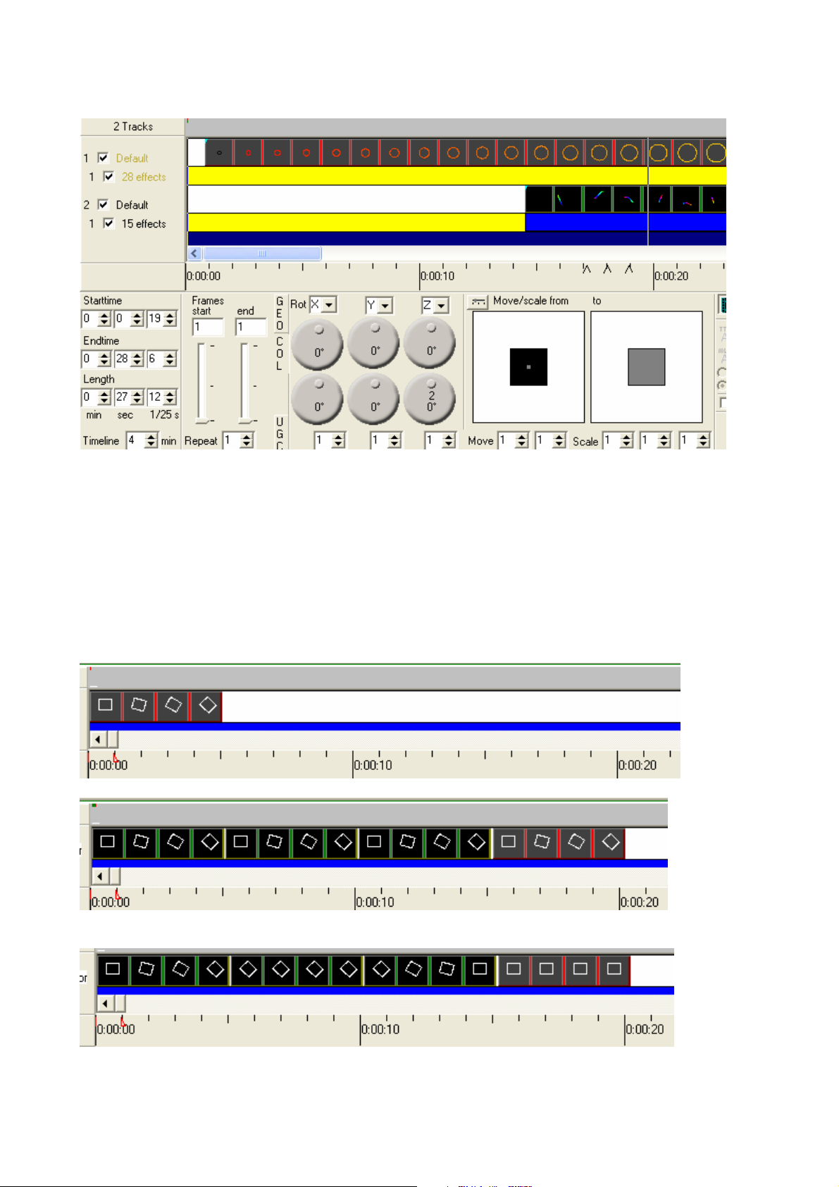
From the local menu you can swap/assign the start/end effects of a scene. This can be helpful when
copying scenes as in the following simple example:
We start with a simple rotation:
Copy the scene 3 times:
Now from the local menu select “Change effects” and then “Set all to end vals” for the second
scene, “Reverse all effects” for the third and “Set all to start vals” for the last scene
Now we have a rotation to the right followed by a static picture, then roation back, and static again.
© MediaLas Laserproducts GmbH 27/50
Page 28

Scenes can overlap, alhtough this is not recommended. When scenes overlap you may not be able to
access a scene by clicking it.
Overview area
Located above the track area, there is an overview over the current timeline content. Green lines
indicate scenes, the currently selected scene is shown in red. On the bottom and right, a white line
shows the currently visible track area (the “ruler” below the tracks). A red line on the bottom shows
the begin/end marker. You can also click on the overview to position the time marker. In the image
above you can see one scene on track one and 3 scenes (the second of which is selected) on track
two.
Tip: Set the length of the timeline (bottom left corner) to the same length as your audio file. This
makes it easier to zoom in and out.
© MediaLas Laserproducts GmbH 28/50
Page 29
Effect tracks
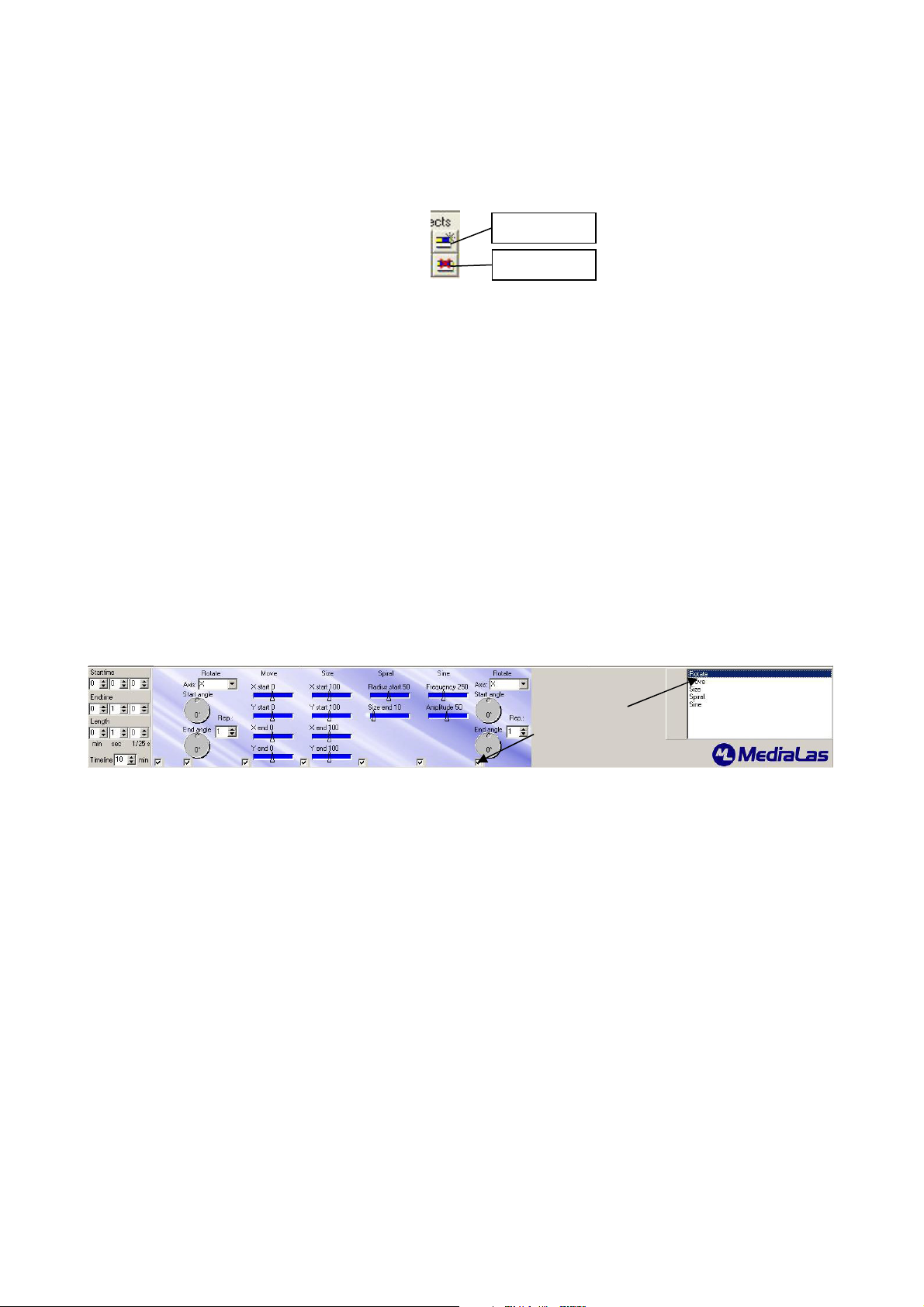
You can place effects on the 2 effect tracks independently from scenes. This is quite helpful when a
certain effect should span over more than one scene, or only part of the scene. Also, various effects
can be used at the same time to get interesting movements.
Add effect
Delete effect
Adding effects:
Select the track for which you want to add an effect track (click on the label). Then add an effect
track with the “Add Effect Track” button, and then add an effect with the “Add Effect” button
above the timeline.
Deleting effects:
Use either the buttons or simply right click onto a scene and select “delete scene”.
Each effect can be stretched to any desired length, by using the mouse pointer. Click left on the end
or the beginning of an effect, hold mouse button, and stretch the effect length. The length is not
limited to a specific scene. You can use an effect over the entire timeline, if you want to do so.
The Effects
The following picture shows the currently available effects, which can be placed anywhere on the
timeline:
Click to add effect
Click to disable an effect
Add single effects by clicking on the desired effect on the list on the right. Use the check boxes
below the effects to turn them off, the checkbox on the left disables all effects. To delete effects use
the local menu (right mouse button).
© MediaLas Laserproducts GmbH 29/50
Page 30
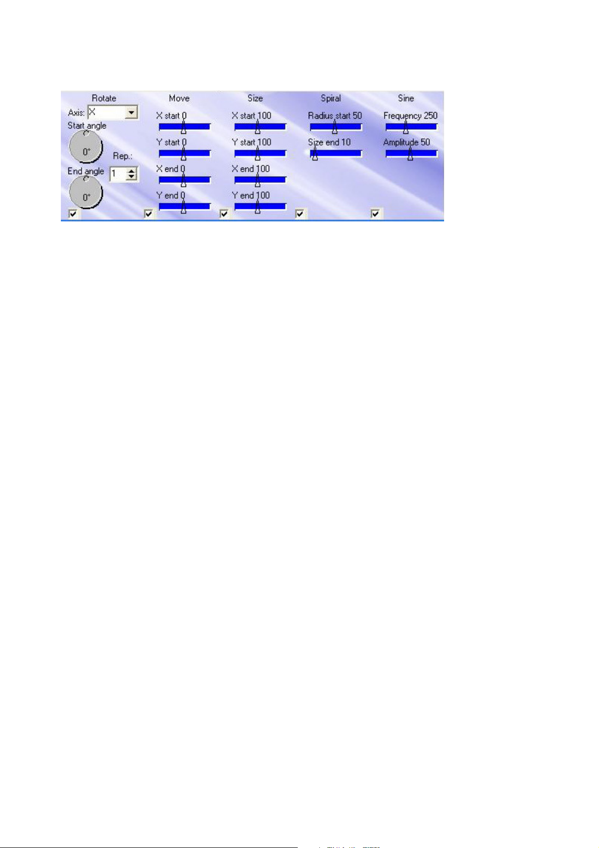
Available effects:
Rotate: Allows to rotate a frame or framelist or scene in all axis. Very useful: By using two
different axis, both rotations add themselves for very interesting effects. Dropdown box selects the
rotation axis X, Y or Z. Adjust the rotation with the two handles, and set the repetetion rate in the
select box. If the checkbox in the lower left corner is checked, the effect is active. If this box is
unchecked, the effect will be disabled.
Move: Allows to move a frame or framelist or scene in X and Y. Adjust the starting coordinates
with the two top sliders, adjust the end coordinates with the lower two sliders. If the checkbox in
the lower left corner is checked, the effect is active. If this box is unchecked, the effect will be
disabled.
Size: Allows to resize any frames, framelist or scene static or dynamic. Adjust the starting size with
the two top sliders, adjust the end size with the lower two sliders. If the checkbox in the lower left
corner is checked, the effect is active. If this box is unchecked, the effect will be disabled.
Spiral: Absolute effect tool. Place an adjustable spiral movement to your timeline! Adjust the effect
with the two sliders, while Radius start adjusts the large radius of the spiral, Size end adjusts the
end radius of the spiral. If the checkbox in the lower left corner is checked, the effect is active. If
this box is unchecked, the effect will be disabled.
Sine: Add a sine wave to the animation. With this effect, phantastic effects can be achieved. Adjust
the frequency and amplitude of the sine wave with the two sliders. If the checkbox in the lower left
corner is checked, the effect is active. If this box is unchecked, the effect will be disabled.
All effects can be used multiple times in one effect layer.
© MediaLas Laserproducts GmbH 30/50
Page 31
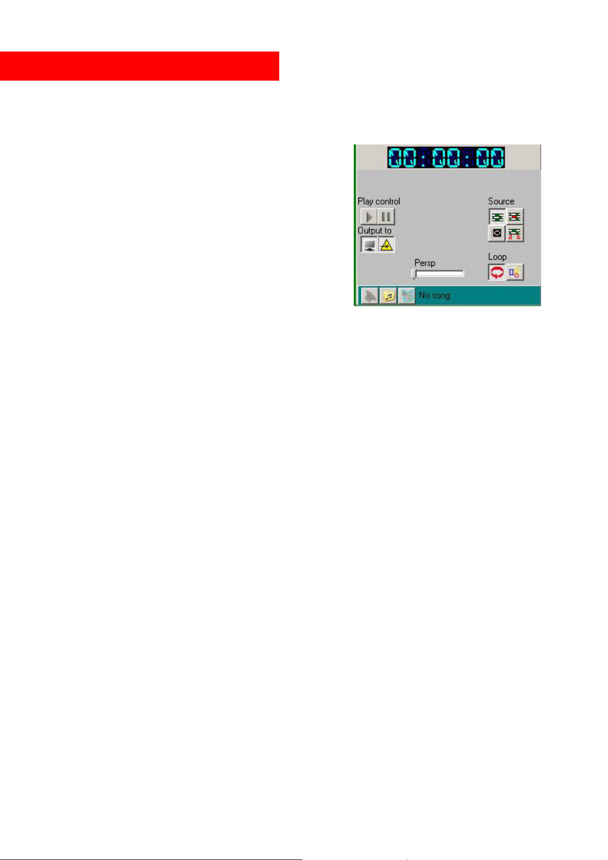
Play a show on your laser projector.
After designing of show is finished, the show should be saved onto your harddisk or flashdisk. We
recommend futhermore, to save the show on a regular basis all 10 minutes or so. It can be done
easily by clicking on the dropdown menu “file”.
Playback control
The buttons labeled “Play control” start/end/pause the
playback. If you click on “Play”, your show, or part of the
show, starts to play on the selected output device,
depending on the selected source.
“Output to” lets you select monitor and/or output to laser
projector. If the laser symbol is not selected, the entire
show plays in the preview window only. Also, if you
experience a slowdown of your computer while
outputting to the preview window, simply unselect the
preview.
“Loop” plays the show in a continous loop. Be careful not to use this button during a normal laser
show, or your show will start again from beginning.
When both play and pause buttons are pressed, you can set and/or drag a position marker by
clicking on the “ruler” below the tracks or the overview area above the tracks. Move this position
marker on the timeline, this allows to scroll through the show. At the same time you are able to
scroll frame by frame through the entire show, by using the cursor keys Left and Right on your
computer keyboard. With the Up and Down keys, the show is scrolled in 10 second steps. If music
playback is selected, also the music will be played. The more you scroll, the stranger the music
sounds.
User selected time:
You can press Ctrl+B and Ctrl+E to set a begin/end marker anywhere on the timeline. Please note,
that an end marker can only be set after the begin marker.
Source selection
The buttons in the “Source” section select the part of the timeline that is displayed:
Entire show from start to end
The currently selected scene
A single frame, which is currently displayed in the editor window
User time from begin to end marker
Add music to your show
You can load a song to be played with the show. Open a music piece with the folder button. Now
select the wave or mp3 file, or even a song from a music CD. Press the speaker button to enable
music playback. Now, the music plays on any output. If will even scroll automatically to the correct
time frame, if source selector is set to other playback format than entire show.
© MediaLas Laserproducts GmbH 31/50
Page 32
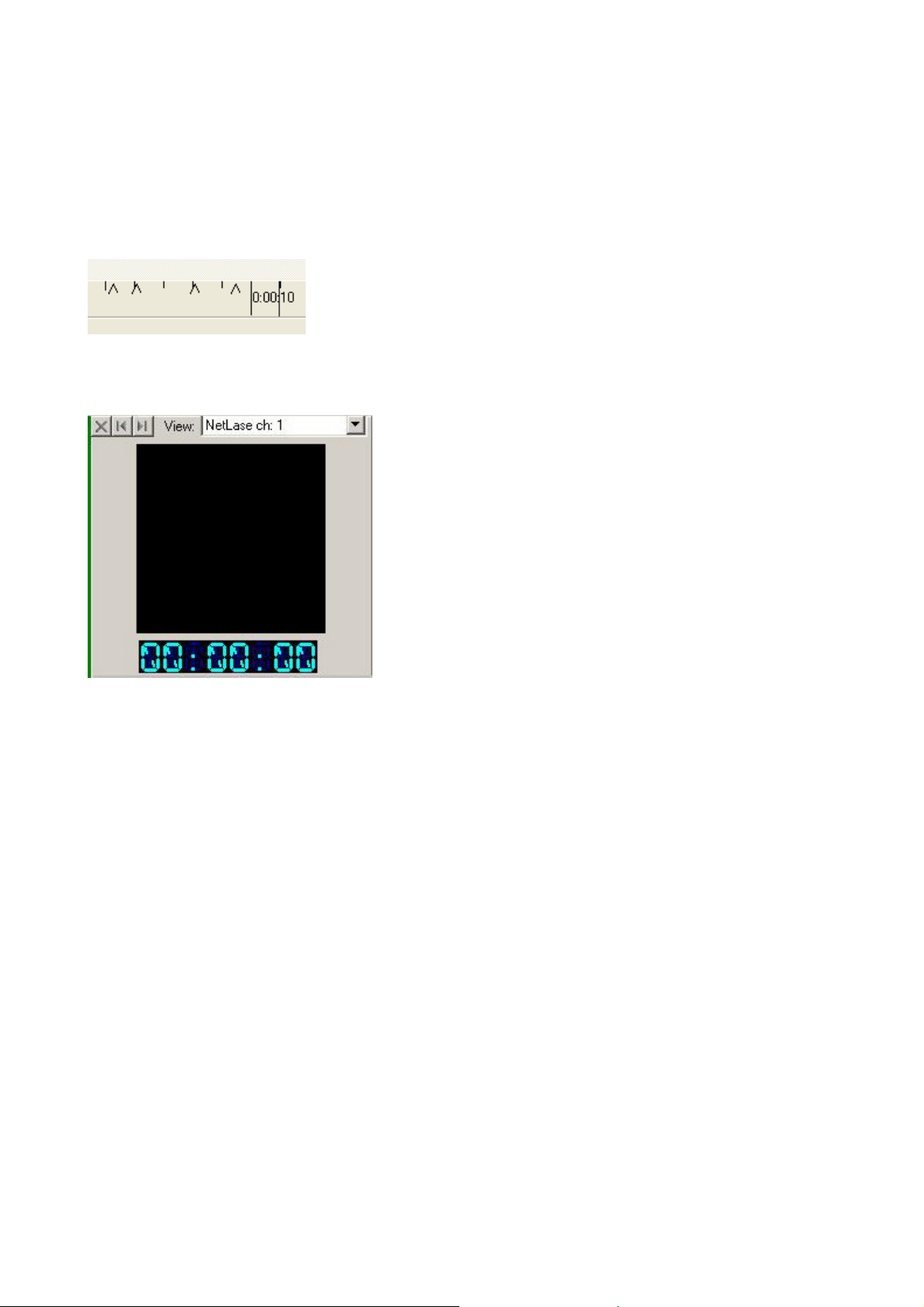
Mark highlights in the music with beat markers
Beat markers are very useful, if a new beam show is created. Open a music file, and press play.
Now, during listening to the music, you can hit the space key to put markers on the timeline while
the show is played back. This allows you to put scenes to specific positions, which are premarked in
the timeline. The marks will be displayed as black triangles on the “ruler”.
To delete the marks after show creation is finished, press Ctrl+space.
Preview window
If not in playback mode, or during frame editing, the preview window on the top right on the main
screen shows an overview of the frame editor. Otherwise, the preview window will display the
current content, played back on the selected physical projector, when monitor output is enabled.
The drop down box on the top of the preview window shows you all available physical projectors,
which are currently in the setup up. Depending on the selection, the preview window will show the
content of the selected projector.
When zoomed in, you can drag the visible grey area around to see high resolution previews of
specific scene content.
The time code display, based below the preview window, shows the exact running time, in minutesseconds-frames, while frames can be 0 - 25
Special function: Show blanking lines
The button, which you can find in the UGC settings, shows a very special debugging function, snd
should be carefully and properly used. After this function is selected, all the color and blanking
outputs on your interface box will be set to fully high level. This means, all your lasers in your laser
projectors are set to full power, and do not modulate anymore. This allows to debug errors in the
frame, or to measure your laser output power without any blankings in between. All lasers are set to
100%, and the accurate output power of the lasers can be measured accurate.
© MediaLas Laserproducts GmbH 32/50
Page 33
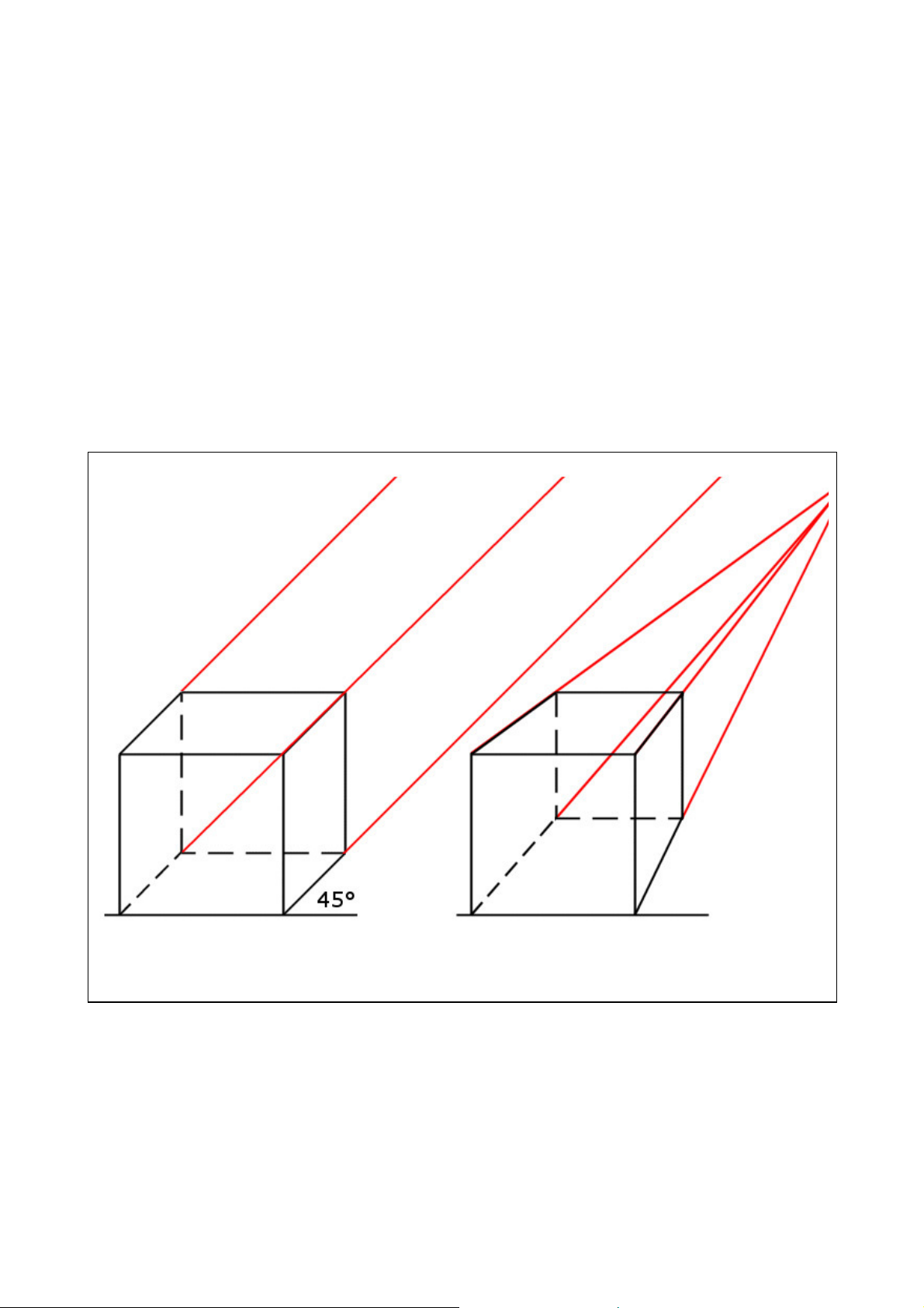
Special function: Perspective (Persp)
Another special function is built into the playback module – the perspective slider. It could be
interesting to play around with this slider a bit, since you cannot destroy anything in the show.
Under normal circumstance, or if the slider is fully in it´s left position, all rotations, movements and
other 3D functions, are played back in parallel perspective, where there is no imaginary viewpoint
in the Z-coordinate. A square, which is rotated in X or Y, will just increase or decrease it´s size in
the desired axis. All sides are parallel during rotation. This is not useful for graphical applications,
but very useful for beamshow applications.
As soon as you apply a value to the perspective slider, an imaginery Z viewpoint is set “behind” the
normal projection area. The same square, rotated by X or Y, will now zoom in 3D, in central
perspective, where one end of the square, which rotates towards the viewpoint, gets smaller, and the
other end, rotating towards the observer, will increase it´s size. The rotating parts are no more
parallel.
Viewpoint
Parallel perspective
Central perspective
To learn more about this slider, simply create a square in the editor, move it to the timeline, and
apply a 360° X rotation. Now play back this rotation in loop mode, and move the slider back and
forth. Interesting, isn´t it?
© MediaLas Laserproducts GmbH 33/50
Page 34
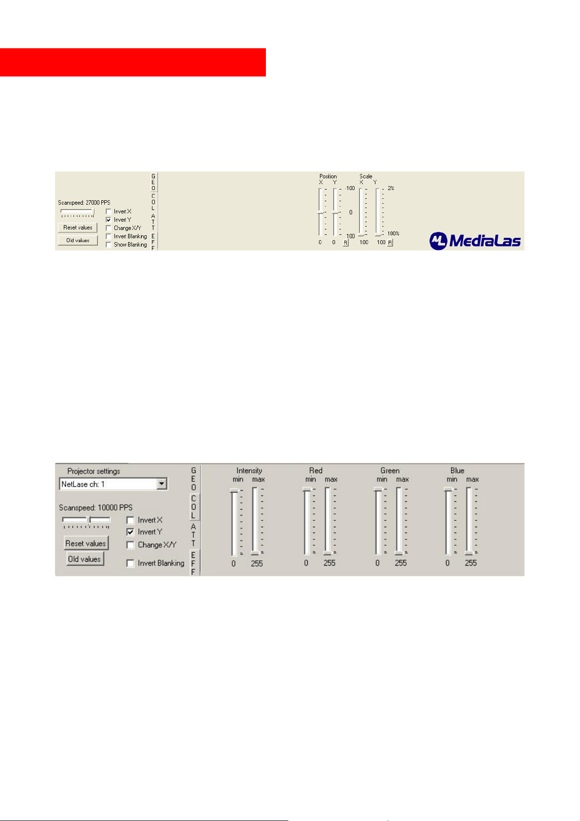
The Universal Geometric Corrector
Mamba Elements contains a very sophisticated geometric correction tool, that allows multiple
correction to the projected image, like position, size color alignment and scan speed settings. Each
physical projector holds fully independant functionality. Depending on the projection angle, the
projecting image could be distorted in many ways and directions. These distortions can be corrected
to almost any projection surface.
This is the panel interface of the UGC, which shows now the geometric correction, and the scanner
settings. On the left hand side, the projector can be set up in basic geometry and speed. Each axis, X
or Y, has it´s own mirror or invert checkbox. Furthermore, X and Y can be interchanged. This could
be necessary, if the projector is mounted 90° turned on a side truss. For some older style lasers or
incompatible projectors, the blanking can be inverted. The scanspeed slider sets the scanspeed per
physical projector from around 1,000 pps to the maximum range. This maximum range can be set to
a specific maximum value in the settings menu, to avoid accidential overdrive of the galvos in the
projector.
The sliders adjust position and scale. Please note, that position and scale can hold a maximum value
of 100 in addition. If you like to adjust the position, the scale must be less than 100%.
To set the color balance of an RGB system, click the COL-tab between projector settings and UGC
sliders. There are two sliders for each color.
The min fader sets the start up value during modulation for each laser color. Laser drivers do not
offer a 100% linear analog input voltage. Some lasers start to light up on different levels than
others. With the min slider, these switch on levels can be adjusted.
The max fader sets the maximum output power per laser color. If your color balance is bad, single
colors can be reduced in output power. This could be necessary on cheaper systems, where green is
too powerful, and does not match to red and blue.
Intensity slider is mainly used for single color laser projectors, and offers the same functionality
like color sliders.
© MediaLas Laserproducts GmbH 34/50
Page 35

The attenuation map
With the Attenuation Map, it is possible to set various laser safety zones to your Laser Output. This could be very
important for laser safety in case of audience scanning. Click on the “ATT” button, which appears in the effects panel if
you click the UGC Button, to adjust the attentuation map. On first time you do this, it will appear a small window in the
effects panel which is completely white, which means that there are no laser safety zones adjusted. To adjust your own
safety zones, first enter a number between 0 and 100 in the box next to the attenuation window. The number is a
percentage. For example: 0 means no attenuation, 100 that the laser will be fully blanked and 50 means that the
laserpower is alleviated for 50 percent. Note: Lasers do not offer a 100% linear analog input voltage. If you entered a
number, simply draw rectangles, with the rectangle tool, everywehre in the frame editor where you want to add the
safety zones with that special percentage. After that, simply click the “Apply Attenuation” button. Your attenuations
will directly appear in the attenuation window. The more black the rectangles are displayed the bigger the percentage
for that zone. You can adjust as many zones ( with specificated percentage ) as you want, but be sure that you are
always entering the percentage before you click the apply button. To delete the whole attenuation map, simply enter 0 in
der percentage box and draw one big rectangle over the whole frame, then click “Apply Attenuation”. Your attenuation
window will be completely white again. Tip: It could be very helpful ( for editing the various zones later ) to draw
various ractangles, with different percentages, in one own frame and safe this as a frame list. This will allow you, to
adjust the percentages of the zones easier later.
© MediaLas Laserproducts GmbH 35/50
Page 36
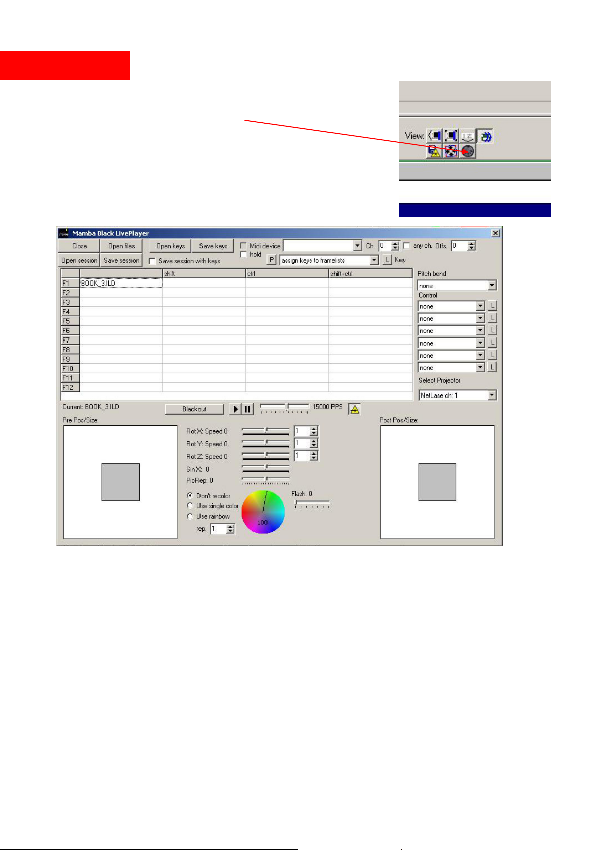
Live player
The built in LivePlayer is a cool tool for doing live laser shows in
real time. Start the Live Player by clicking on the button:
The Live interface main screen opens:
As long as there are no frames or shows assigned to the cue buttons, the sliders for rotation etc. will
not show up.
You can only use framelists, not shows, since shows are just a part of a final running laser show. If
you want to use a show in Live, export it to a frame list, and assign the frame list to a button (slot).
Open files will load the frame lists starting with the first slot. To assign frame lists to a specific slot,
double-click that slot.
Start playback (Play has to be active) by pressing the function key and modifier keys, or mouse
click. Stop with escape or the stop button. Make sure to press the laser output button, or there will
be no laser projection.
© MediaLas Laserproducts GmbH 36/50
Page 37

Live Effects
The effect sliders offer realtime effects, which can be used during playback of a live show. Add a
rotation about x/y/z by pressing the x/y/z keys. Decrease speed with shift+x/y/z. Reset with
CTRL+x/y/z. Similarly use the s key for a sine wave and r (picture repeat) for changing playback
speed. If you are more familiar with your mouse or trackball, simply use the mouse to move the
sliders.
For resetting slider values to zero, simply move your mouse on the desired slider, and press the
right mouse button.
Use the grey areas to move/resize the output before or after the effects.
Midi control
Any standard Midi device can be used to trigger realtime live output. Check Midi device and select
the device from the list. Select the channel your device is sending on. Note 0 (49, etc) will stop
playback, notes1-48 (50-97, etc.) select the frame lists, adjust the offset to shift the range on the
keyboard. When hold is checked the frame list will be played until another is selected, otherwise
just as long as the key is pressed.
To teach in the Midi notes, you can find a button “L” to the right of the Midi control fields. Press L
and simply touch the desired key on your Midi keyboard. Now this key is assigned to the
appropriate slot/frames.
More info coming soon!
© MediaLas Laserproducts GmbH 37/50
Page 38

Import and export shows and frames
Mamba Elements is created with the idea of maximum flexibility in interacting with other laser
software programs, and in the ability to create a lasershow, which is licensed to a specific dongle
number. This allows a professional show user, to handle licenses easy and sell laser shows without
the risk of illegal duplications to non licensed users.
Any standard .ild frame can be imported to Mamba Elements, as long as the standards of the
International Laser Display Association is followed in the frames. Unfortunately, not all laser
software programs follow these standards, even if they claim so. If Mamba Elements finds a frame
format incompatible, it will either refuse to load the frames, or load it with point errors. If a point
error occurs, do not condemn Mamba Elements! First check out, if the exported .ild file is fully
compatible with the standard.
To ensure time synchronity on imported shows, Mamba Elements allows the selection of a specific
frame number per second. The standard frame speed is 50 fps (frames per second).
!!!!! Only shows, which are legally owned you yourself, should be exported and transported
to other software systems. Do NOT transfer unauthorized copied shows!!!!
© MediaLas Laserproducts GmbH 38/50
Page 39
Setting up Mamba Elements
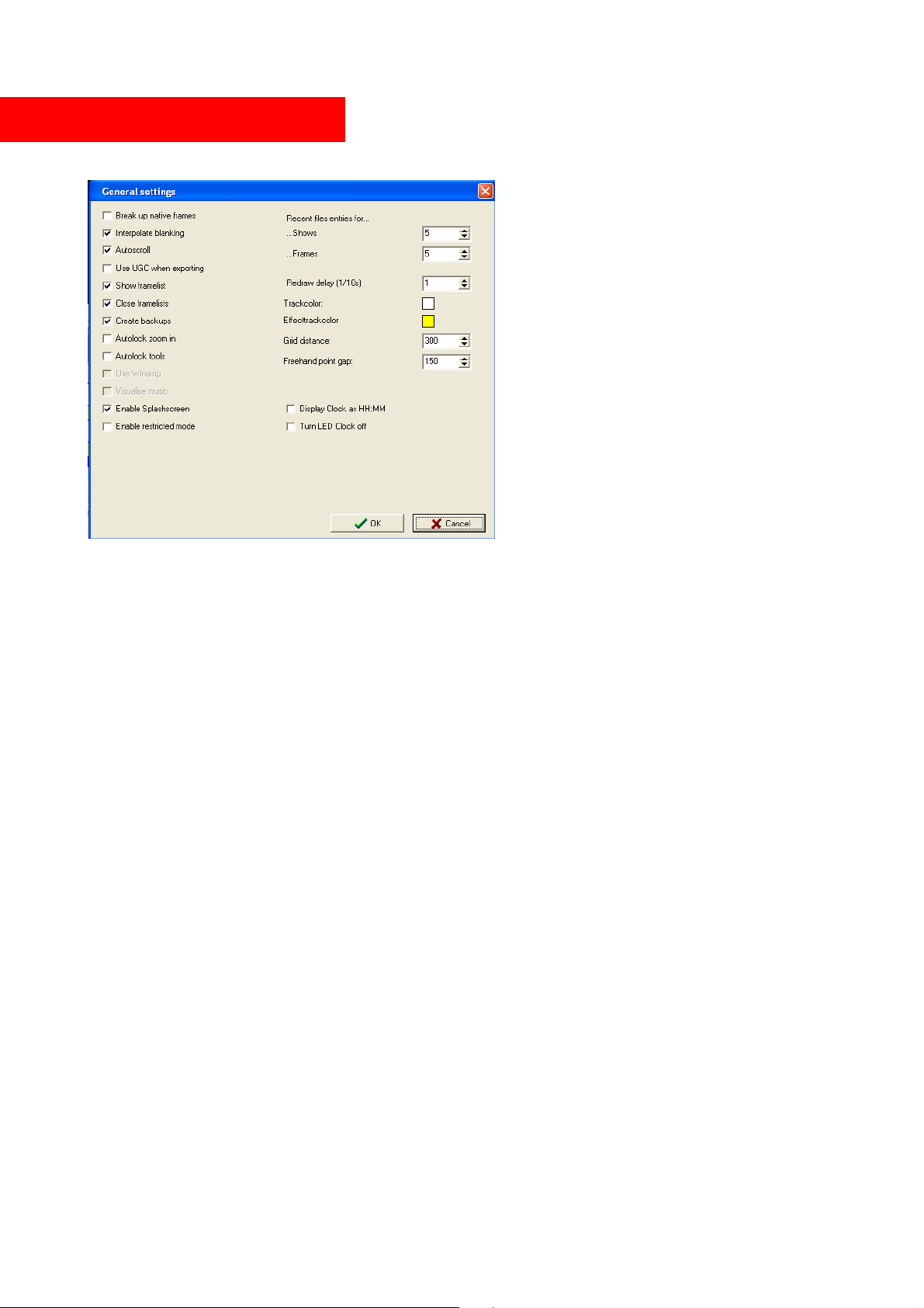
General settings
Break up native frames: When checked,
point oriented frames (.ild, .fl?) will be
separated into different objects at blanking
points. If unchecked, they will be treated as
one object (needs less memory). Has no
effect on .fra frames.
Interpolate blanking : Adds additional
interpolation points to the blanking
lines. This should be checked, if you
experience unnecessary fading lines
between displayed objects, especially
on slow scanners.
Autoscroll: The timeline will scroll to the
right when playback time reaches the end
of the visible area. This should be checked
only if a fast graphics adaptor and computer is used. On slow computers, it might interfere with the
laser output, and the output could stuck during scrolling.
Use UGC when exporting: When checked, the “save output to file” function will use the current
UGC settings. Images in the frame list could be distorted. Do not use this function, if you want to
transport a show from one software to another software. Use this function, if a framefile for the live
player is exported.
Use shift when exporting : If a framelist will be exported as .ild point oriented format, it might be
necessary to check this box. This will include your blank shift settings during export process.
Show framelist: Selecting a scene will automatically change to the frame list, which holds the
frames used in this scene.
Close framelists: When checked, all frame lists are closed before opening a show or selecting new
show. If unchecked, frame lists will stay in the memory.
Redraw delay: Increase this value if the scrolling of the timeline gets too slow, especially on slow
computers. The redraw of the timeline will be delayed, which is time saving on slow computers. On
fast computers, set to 1.
Check for updates: If an internet connection is established, Mamba Elements will check for
updates on each start up. Additionally, the checking interval can be set. If you do not have internet
available on your computer, uncheck this function. Mamba Elements will show a warning, if this
function is activated, but there is no internet access.
Freehand point gap: Distance for interpolation during free hand drawing in the frame editor.
Enable splashscreen: Displays the MediaLas logo during startup of Mamba Elements.
© MediaLas Laserproducts GmbH 39/50
Page 40
Output settings
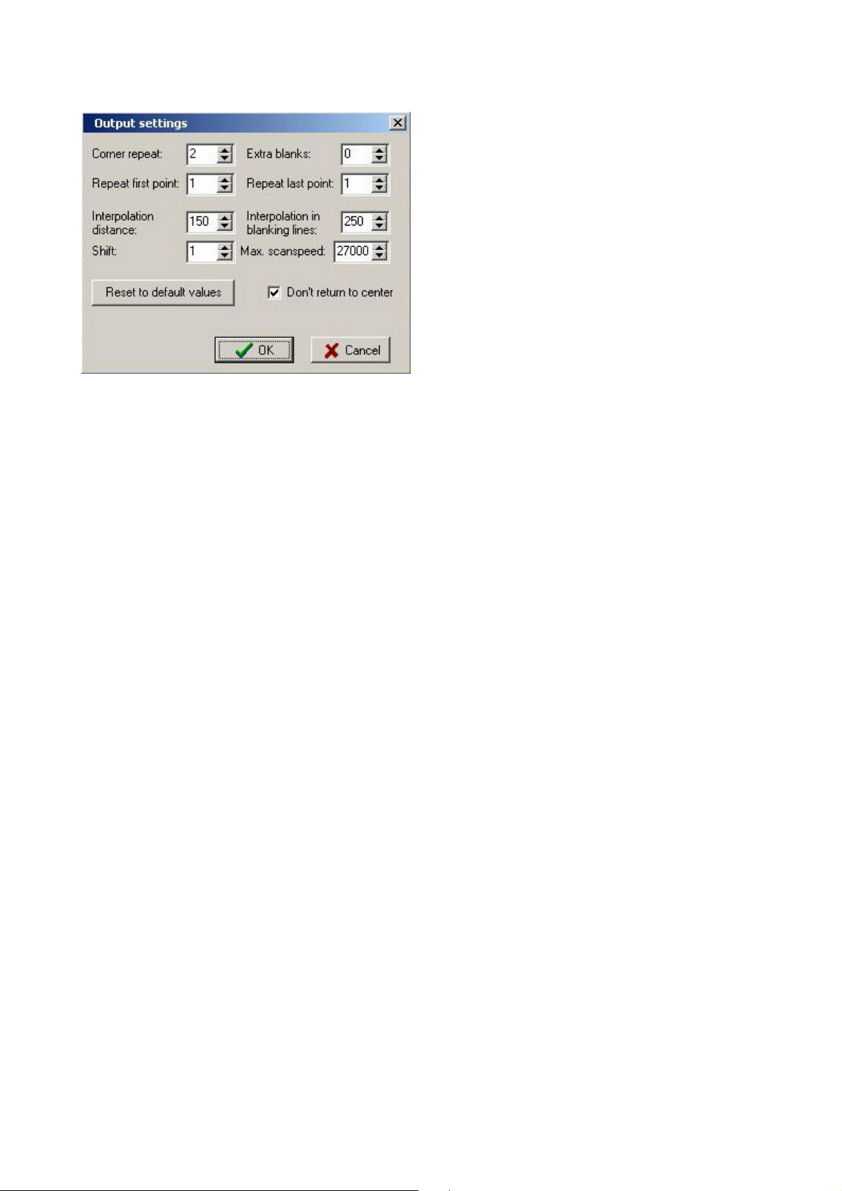
Here, the quality of the output to the laser
projector is set up. Depending on scan speed,
galvo quality, and kind of projection, these
settings have to be adjusted for proper function of
your projector.
Use some test patterns and play around with the
settings, for a better understanding of your galvo
system and speed.
Corner repeat: Sets repetition rate on corner points.
Repeat first point: Sets repetition rate at the first point of the frame. Could be necessary on slow
laser drivers.
Extra blanks: Sets extra blanking points. Could be necessary, if laser driver does not switch off
immediately.
Repeat last point: Repeats the last point of a frame. Could be necessary on slow scanners.
Interpolation distance: Has a large influence on the projection quality, and on projection speed.
The faster your galvo scanner can go, the high this value can be set. Each line will automatically be
interpolated during output. This value sets the point distance. The lower the distance, the more
interpolating points will be added during output.
Interpolation in blanking lines: During blanking, the blanking jumps can be interpolated to ensure
a good projection quality. This function is only available, if activated in the general settings menu.
Shift: (Also called blank shift) Is the delay time between galvo speed and laser modulation speed.
Since usually both speeds differ, there might be an adjustment necessary, which can be done with
the Shift value.
Max scanspeed: This sets the maximum value of the scanspeed slider in the UGC interface.
Adjust the output settings
To adjust output settings to your projector or XY scan system, the usage of the standard ILDA test
pattern is recommended. The following pages will display a summary of this test pattern, the basic
functions of the pattern contents, and tuning procedure of your galvo systems, according to this test
pattern. If a MediaLas scanning system, such as TeraScan or CT-Set is used, the setup and
alignment is very easy. More help and information can be found in the MicroAmp manuals. The
following pages are provided by the Internation Laser Display Association ILDA.
© MediaLas Laserproducts GmbH 40/50
Page 41
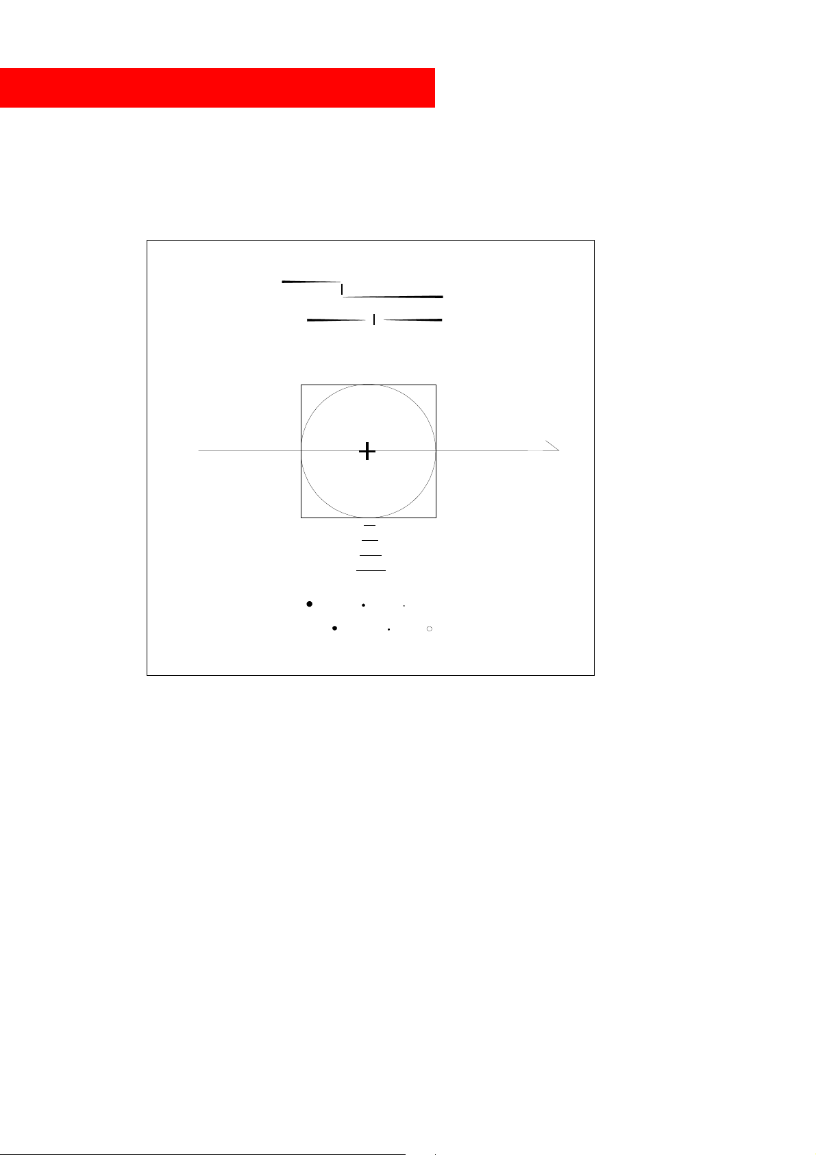
ILDA TEST PATTERN TUNING PROCEDURE
This procedure covers the stanbdard 30K ILDA Test Pattern tuning. This pattern can be found in
the frames folder in the Mamba Elements directory.
Y
X
12/30K
Figure 1
ILDA
INTRODUCTION
The ILDA test pattern very accurately defines mechanical laser scanner response. The test pattern's
primary use is in alignment and calibration of galvanometer based laser vector graphic projection
systems. This known response is crucial to proper reproduction of interchanged imagery. Use this
test pattern to calibrate programming and playback equipment prior to the commencement of image
creation.
The point output rate associated with this ILDA Standard defines only the rate which must be used
during scanner adjustment. This standard does not effect the point rate at which subsequent images
may be generated or reproduced.
© MediaLas Laserproducts GmbH 41/50
Page 42
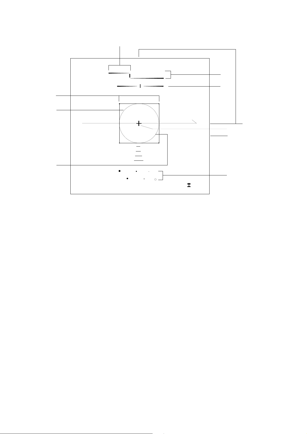
A3
A2
B3
Y
B1
B2
A4
A5
A6
B3/B4
A1
12/30K
X
I LDA
Figure 2
A. XY Scanner B. Blanking signals (use blank shift to correct)
1) Correct scanner speed 1) Correct scanner speed
2) Correct damping 2) Correct damping
3) Same scanner speed 3) Amplitude
4) Inverts 4) DC offset
5) Amplitude
6) Centering
Note: The 12/30K indicates the output speed for this test pattern in points per second. Your image
source must output points at 12,000 or 30,000 points per second (+/- 1%) for this test pattern to
work.
ADJUST XY SCANNERS
This procedure assumes scanners and blanking system are pre-tuned to a state of stable operation.
Consult manufacturer's documentation for information on scanner start-up from a completely
inoperative state.
Use caution when adjusting scanners. Galvanometer and motor scanners can be easily damaged
through careless or rough adjustment. Tuning should be performed by personnel with suitable
knowledge and experience. Always watch the output carefully, when images begin to break-up this
© MediaLas Laserproducts GmbH 42/50
Page 43
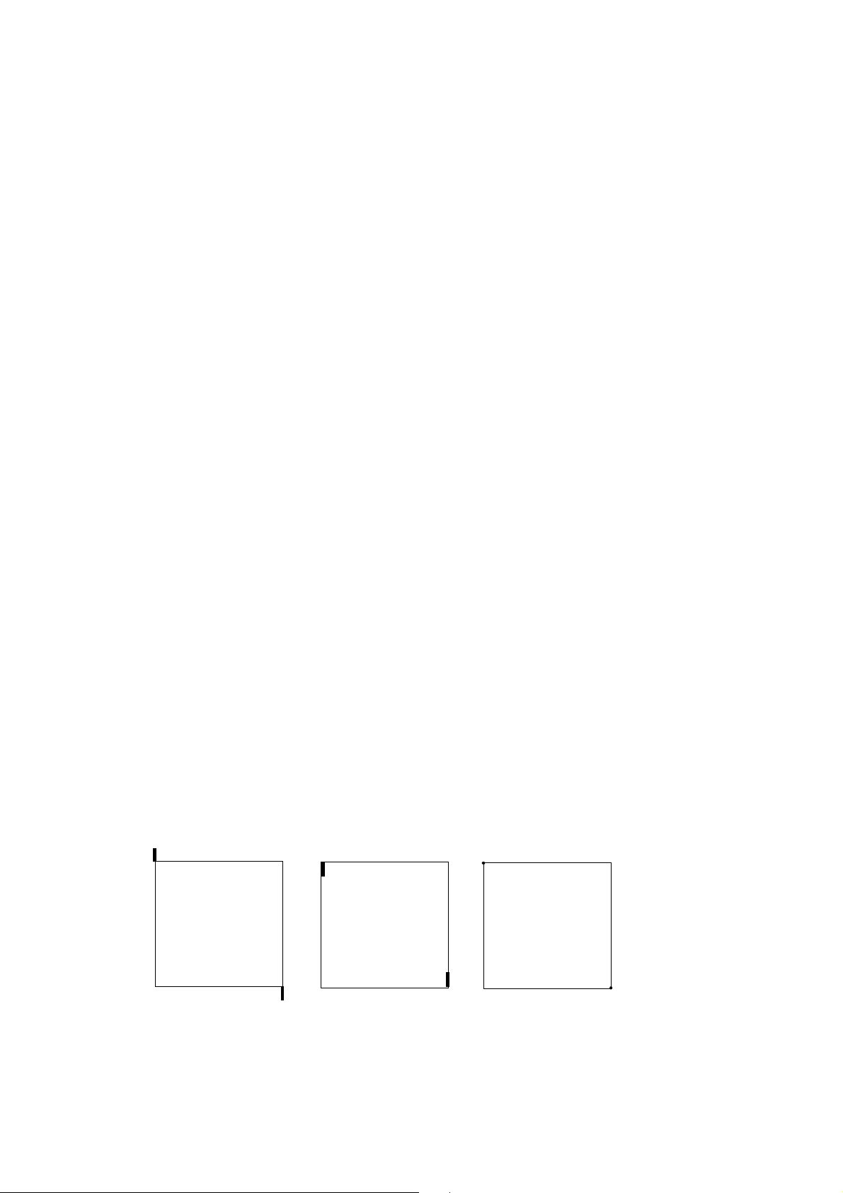
is a warning that harm may be near. Never allow scanners to oscillate! Read manufacturers data on
scanner adjustment carefully before commencing any tuning.
For additional information about use of the ILDA Test Pattern read, "Using the ILDA Standard Test
Pattern".
1. DISPLAY TEST PATTERN
Display the ILDA Test Pattern image at 12,000 (12K) or 30,000 (30K) points per second depending
on desired tuning, or simply adjust to the scanspeed you want to tune to. Example: If you like to
tune your scanners to 40k, adjust scanspeed to 40k with the scanspeed slider. If the slider does not
show the value up to 40k, change settings in the “output settings” menu point.
To use the test pattern correctly, it must be scanned small to prevent distortion of the circle. For
30K tuning this about 8 degrees optical, which equals to a projection size of 14cm at 1m projection
distance.
2. ADJUST INVERTS
Refer to figure 2; A4.
The Y should appear at the top of the image. The X should appear at the right hand side of the
image. If either of these is reversed, invert the signal at the driver card or at the source as
appropriate. Mamba Elements also offers the invert switches in the UGC, please read this manual
for proper usage.
3. ADJUST Y DAMPING
Refer to figure 2; A2.
Observe the lower right corner of the inner square, adjust the low frequency damping until a small
amount of “overshoot” is observed. See figure 3. The length of this overshoot should equal
approximately 2/3 the height of the word “ILDA” in the test pattern.
For scanner drivers equipped with only a single damping control: Perform all adjustments for low
frequency damping and omit high frequency damping procedures.
Overshoot Undershoot Proper Damping
© MediaLas Laserproducts GmbH 43/50
Page 44
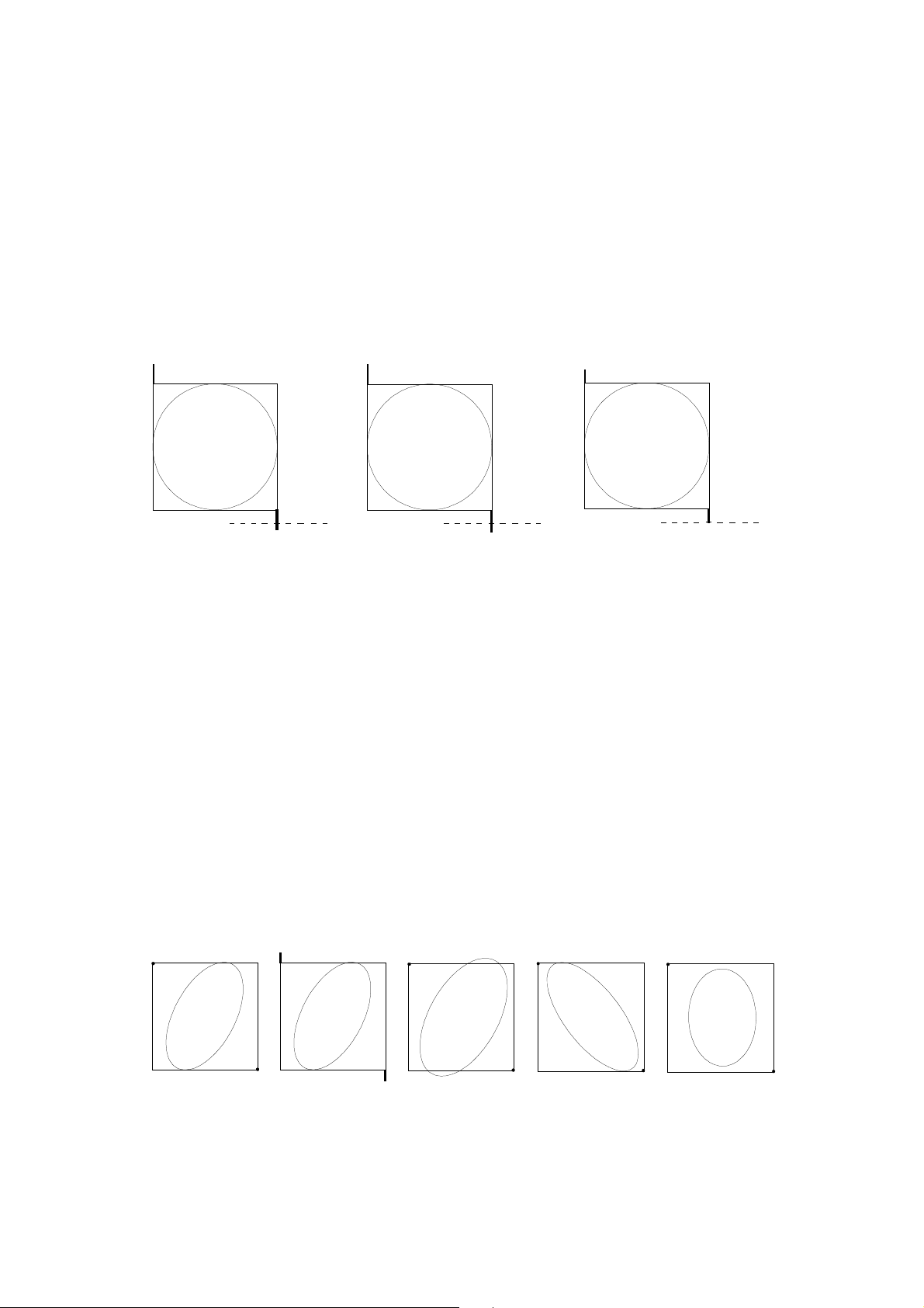
Figure 3
Adjust the high frequency damping up or down a small amount. Notice that the overshoot line
becomes slightly longer or shorter as you do this. If you increase or decrease the high damping too
far in either direction, the overshoot will become longer. By carefully adjusting in both directions
you will find the point where the overshoot is at its shortest length.
Use extreme precision and diligence, the perceived change is very slight. This adjustment is of
utmost importance for proper tuning.
High Damping too low High Damping too high Just right
Figure 4
Return to the low frequency damping and decrease to “tuck” the overshoot back into the dot at the
corner of the square. Use caution not to create undershoot which is very difficult to see. See figure
3.
If top and bottom of the circle touch the top and bottom edges of the square (regardless of the phase
of the circle), skip to step 5, "ADJUST X DAMPING". See figure 5.
Correct Incorrect Incorrect Correct Incorrect
Figure 5
© MediaLas Laserproducts GmbH 44/50
Page 45
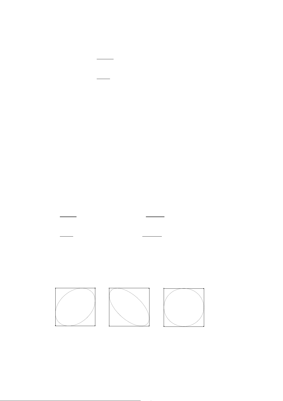
4. ADJUST Y SERVO GAIN
Refer to figure 2; A1
If top and bottom of circle are smaller, or inside the square, increase servo gain and return to step 3,
"ADJUST Y DAMPING".
If top and bottom of circle are larger, or outside the square, decrease servo gain and return to step 3,
"ADJUST Y DAMPING".
5. ADJUST X DAMPING
Now that the Y axis is correctly adjusted, do not adjust it again.
Observe the upper right corner of the inner square. Adjust the low frequency damping until a small
amount of overshoot is observed. The amount of overshoot should equal approximately 2/3 the
height of the word “ILDA” in the test pattern.
Adjust the high frequency damping to where the length of the overshoot line is minimized, as was
done in step 3 for the Y axis.
Decrease the low frequency damping to “tuck” the overshoot back into the dot at the corner of the
square. Again, use caution to not go too far and create undershoot.
6. ADJUST X SERVO GAIN
If the circle is smaller than the square in the X axis, increase the servo gain and return to step 5,
"ADJUST X DAMPING".
If the circle is larger than the square in the X axis, decrease the servo gain and return to step 5,
"ADJUST X DAMPING".
At this point the circle should touch the square at four points and be perfectly round. If so, go to
step 7, "ADJUST IMAGE SIZE".
Inco rrect Inc o rrect Correc t
Figure 6
© MediaLas Laserproducts GmbH 45/50
Page 46

If the circle touches the square in both axis, but the circle is not perfectly round, very carefully fine
tune damping and servo gain with step 5, "ADJUST X DAMPING", repeatedly, until circle is as
round as possible.
If perfect circularity is still not attained, fine tune adjustments for damping and servo gain carefully
for Y axis again. Return to step 3, "ADJUST Y DAMPING".
If phase of circle is still not perfect, repeat damping and servo procedures for the X-axis while
slowly increasing or decreasing the servo gain. In worst cases,
Repeat previous step until the circle is perfectly phased and damping is correct. Refer to figure 6.
7. ADJUST IMAGE SIZE
Refer to figure 2; A5.
Reset image signal size to normal at the signal source.
Adjust X and Y image amplitudes to fill screen. If screen area is not square, adjust sizes to fill the
largest square that fits on the screen. The outside edge of the test pattern is the maximum scan area.
8. ADJUST DC OFFSET
Adjust the DC offsets so the cross in the middle of the test pattern is at the center of the screen area.
Make only minor adjustments with DC offsets. Larger adjustments should be made by physically
rotating the scanners in their mounts.
TIPS:
Any time you adjust servo gain, the damping(s) must be adjusted as well. The inverse of this is also
true.
Scanners are inherently imperfect. A well adjusted XY set may be achieved with some compromise
to perfection. However, the scanners of today are of higher quality and usually will tune near
perfectly. Be patient, don't give up too soon!
Correct wrong blanking lines on top of the image (B1) with the blank shift adjustment in Mamba
Elements.
--------- End of test pattern procedure. C by ILDA ---------
© MediaLas Laserproducts GmbH 46/50
Page 47
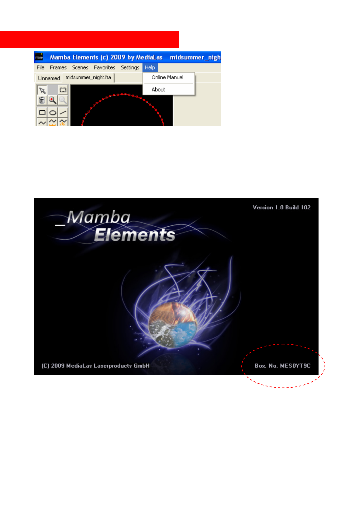
Updates / Help / Manuals / Serial number
By clicking on the help menu, the dropdown opens. Here, you find the latest version of the manual
in pdf format. To check for one of these, a working internet connection must be established on your
computer.
If you select the About field, a window opens with the Mamba Elements logo, and the serial
number of your dongle key. This serial number is needed for any update request.
© MediaLas Laserproducts GmbH 47/50
Page 48
Hot key in Mamba Elements
Mamba Elements offers a large number of hot key functions, which helps a professional laserist to
fasten up his daily work in creating professional laser shows. Below is a list of available hot key
functions. The headline states the hot key, while the “+ xxx” mark states the action, in addition to
the hot key.
Strg
+ Objects/Scenes Multiple marking
+ C Copy Scene / Object into memory
+ V Add scene/object from clipboard
+ Rotation wheels Rotation wheel values changes in 5° steps
+ Color wheels Color wheel values changes in 5° steps
+ Editor Actual object gets caught in the grid
+ B Sets begin marker for user time
+ E Sets end marker for user time
+ Space Clears all beatmarks
+ A Selects all scenes on the timeline
+ O Open Show
+ S Save Show
+ N Add Scene
+ D Delete Scene
+ L Toggle autoscroll
Shift
+ Rotation wheels Rotation wheels end and starting values are locked and change
simultaneously
+ Sliders/Moving areas Start & End position or scaleare locked and change
simultaneously
+ Frames in List Selects all frames in the framelist, beginning from highlighted
frame
+ Tool Selected tool is locked for multiple use
+ Rectangle/Circle/ Insert of proportional objects
+ Select region/Zoom Insert of proportional objects
+ Freehand, Polyline, Line Line line is caught in 45° steps
+ UGC / Scale Proportional scale
Strg + Alt
+ O Open Framelist
+ S Save Framelist
+ E Close Framelist
+ A Close all Framelists
+ I Insert Framelist
+ N New Frame
+ L Clear Frame
+ D Delete Frame
+ X Cut Frame
+ C Copy Frame
+ V Paste Frame
© MediaLas Laserproducts GmbH 48/50
Page 49

Strg + Shift
+ Scene Docks selected scene to previous scene
+ X Cut Objects
+ C Copy Objects
+ V Paste Objects
Space
Sets beatmarks on the timeline while a show or a song is
playing
Double click
+ Rotation wheels Resets values of rotating wheels
+ Moving areas Resets values of moving areas
Double click
+ Move / Scaleslider Changes values in 25 steps
+ / -
+ Freehand Changes drawing point distance (shown below editor window)
© MediaLas Laserproducts GmbH 49/50
Page 50

Credits
MediaLas would like to thank the following people and entities, which helped to make this manual
better:
• Vince van Riet (DixiScan)
• Tobias Gebuhr
Keep it coming!
© MediaLas Laserproducts GmbH 50/50
 Loading...