


i
RX8000 Integrated Receiver/Decoders
Software Version 8.22.0
REFERENCE GUIDE
RX8000 Integrated Receiver/Decoders
1553-FGB 101 759 Uen K
www.mediakind.com

ii
bekostnad.
Also, translation into any EC official language of
cost.
εγχειρίδιο είναι διαθέσιμο σε μετάφραση σε αυτή
τη γλώσσα και μπορείτε να το αγοράσετε.
cht
Handbuches in diese Sprache ist gegen
Si no entiende el contenido de este manual. NO
(idioma) previo pago de una cantidad adicional
que deberá abonar usted mismo.
pouvons vous proposer, à vos frais, une version
versione italiana di questo manuale, ma il costo
Se não compreende o texto deste manual. NÃO
português à própria custa.
begrijpt. STEL DEZE APPARATUUR DAN NIET IN
WERKING. U kunt tevens, op eigen kosten, een
Udstyret må ikke betjenes. MEDMINDRE DE TIL
håndbog.
ENGLISH (UK) - READ THIS FIRST!
If you do not understand the contents of this
manual. DO NOT OPERATE THIS EQUIPMENT.
this manual can be made available, at your
SVENSKA - LÄS DETTA FÖRST!
Om Ni inte förstår informationen i denna
handbok. ARBETA DÅ INTE MED DENNA
UTRUSTNING. En översättning till detta språk
av denna handbok kan också anskaffas, på Er
PORTUGUÊS - LEIA O TEXTO ABAIXO ANTES
UTILIZE O EQUIPAMENTO. O utilizador poderá
também obter uma tradução do manual para o
FRANÇAIS - AVANT TOUT, LISEZ CE QUI
Si vous ne comprenez pas les instructions
contenues dans ce manuel. NE FAITES PAS
FONCTIONNER CET APPAREIL. En outre, nous
DE MAIS NADA!
SUIT!
ITALIANO - LEGGERE QUESTO AVVISO PER
Se non si capisce il contenuto del presente
L’APPARECCHIATURA.. È anche disponibile la
Als u de inhoud van deze handleiding niet
Jos et ymmärrä käsikirjan sisältöä. ÄLÄ KÄYTÄ
LAITETTA. Käsikirja voidaan myös suomentaa
HÅNDBOG. Vi kan også for Deres regning
manuale. NON UTILIZZARE
NEDERLANDS - LEES DIT EERST!
vertaling van deze handleiding krijgen.
SUOMI - LUE ENNEN KÄYTTÖÄ!
asiakkaan kustannuksella.
DANSK - LÆS DETTE FØRST!
FULDE FORSTÅR INDHOLDET AF DENNE
levere en dansk oversættelse af denne
PRIMO!
DEUTSCH - LESEN SIE ZUERST DIESEN
Sollte Ihnen der Inhalf dieses Handbuches ni
klar verständlich sein, dann. BEDIENEN SIE
DIESE GERÄTE NICHT! Eine Übersetzung des
ESPAÑOL - LEA ESTE AVISO PRIMERO!
OPERE ESTE EQUIPO. Podemos asimismo
suministrarle una traducción de este manual al
HINWEIS!
ΕΛΛΗΝΙΚΑ - ΔΙΑΒΑΣΤΕ ΠΡΩΤΑ ΑΥΤΟ!
Αν δεν καταλάβετε το περιεχόμενο αυτού του
βοηθήματος/εγχειριδίου. ΜΗΝ ΛΕΙΤΟΥΡΓΗΣΕΤΕ
ΑΥΤΟΝ ΤΟΝ ΕΞΟΠΛΙΣΜΟ. Επίσης, αυτό το
Copyright
© Copyright MediaKind 2019. All rights reserved.
Disclaimer
No part of this document may be reproduced in any form without the written permission of the
copyright owner.
The contents of this document are subject to revision without notice due to continued progress in
methodology, design and manufacturing. MediaKind shall have no liability for any error or
damage of any kind resulting from the use of this document.
RX8000 Integrated Receiver/Decoders
1553-FGB 101 759 Uen K www.mediakind.com

iii
Contents
Chapter 1: Introduction
This chapter identifies the equipment versions covered by this Reference Guide, describes the
purpose of the equipment, and provides a summary of features, controls and indicators.
Chapter 2: Installing the Equipment
This chapter provides product specific installation information including rack mounting,
ventilation and pin-out details of the external connectors.
Chapter 3: Using the Equipment
This chapter details the power up/down procedures and describes the Web Browser interface and
Front Panel LCD menus used for setting-up, configuring and operating the equipment.
Chapter 4: Preventive Maintenance and Fault-finding
This chapter provides details of routine maintenance and servicing, including warranty and
maintenance information, and details fault-finding information for other types of problem which
may be encountered.
Annex A: Glossary
Annex B: Technical Specification
Annex C: Alarm Identifiers
RX8000 Integrated Receiver/Decoders
1553-FGB 101 759 Uen K www.mediakind.com

iv
Introduction
This Reference Guide provides instructions and information for the installation and operation of
the RX8000 Integrated Receivers/Decoders.
This Reference Guide should be kept in a safe place for reference for the life of the equipment. It
is not intended that this Reference Guide will be amended by the issue of individual pages. Any
revision will be by a complete reissue. Further copies of this Reference Guide can be ordered
from the address listed in Customer Services. If passing the equipment to a third party, also
pass the relevant documentation.
Revision History
Issues of this Reference Guide are listed below:
Issue Date Software Version Comments
A March 2011 4.3.2 Allocation of Document identity and
rebrand completion.
B Dec 2012 5.12.0 Major revision of manual:
Section 1: Update to include all RX8000
models.
Section 3: Complete rewrite and inclusion
of RX8252.
Annex B: Update to include technical
specifications of all added options.
C Feb 2014 7.2.0 Major revision of manual:
Section 3: Update of additional
functionality introduced since the previous
issue.
D April 2015 7.14.0 Major revision of manual:
Section 3: Update of new input cards and
additional functionality introduced.
E Sept 2015 7.18.0 Update to Add Cue Tone Splicing
functionality.
F Jan 2016 7.21.0 Update to include support for HEVC
decoding, SDP Field Insertion and subtitle
alarm descriptions.
G July 2016 8.0.0 Update to web interface control with
introduction of new Dashboard View
mode.
H Feb 2017 8.8.0 Director CA, Event ID Filtering examples
and SMPTE 2022-7 Seamless Protection
Switching.
J Dec 2017 8.16.0 Major revision of manual:
Section 3: New functionality for Input
Redundancy Mode; Addressable DPI
(SCTE-35). Updated information on
existing functionality.
K Feb 2019 8.22.0 Major revision of manual:
Rebrand of document
Removal of RX8252, RX8305 & RX8330C
models
RX8000 Integrated Receiver/Decoders
1553-FGB 101 759 Uen K www.mediakind.com

v
Associated Documents
The following manuals/guides are also associated with this equipment:
MediaKind Document Identity Title
174 02-FGB 101 348 Installation, Safety and Compliance Information
Generic Product Information - Reference Guide.
Useful Links:
https://www.mediakind.com
https://mediakind.service-now.com/csp
Trademarks
All best endeavors have been made to acknowledge registered trademarks and trademarks used
throughout this Reference Guide. Any notified omissions will be rectified in the next issue of this
Reference Guide. Some trademarks may be registered in some jurisdictions but not in others.
Registered trademarks and trademarks used are acknowledged below and marked with their
respective symbols. However, they are not marked within the text of this Reference Guide.
Registered Trademarks
Ethernet® Registered trademark of Xerox Corporation.
Dolby®/AC-3® Registered trademarks of Dolby Laboratories Licensing
Corporation.
Dolby® Digital Registered trademark of Dolby Laboratories Licensing
Corporation.
Macrovision
This product incorporates copyright protection technology that is protected by U.S. patents and
other intellectual property rights. Use of this copyright protection technology must be authorized
by Macrovision Corporation, and is intended for home and other limited viewing uses only unless
authorized by Macrovision. Reverse engineering or disassembly is prohibited.
Warnings, Cautions and Notes
Heed Warnings
All warnings on the product and in the operating instructions should be adhered to. The
manufacturer can not be held responsible for injuries or damage where warnings and cautions
have been ignored or taken lightly.
Read Instructions
All the safety and operating instructions should be read before this product is operated.
RX8000 Integrated Receiver/Decoders
1553-FGB 101 759 Uen K www.mediakind.com

vi
Follow Instructions
All operating and use instructions should be followed.
Retain Instructions
The safety and operating instructions should be retained for future reference.
WARNING: Warnings give information which, if strictly observed, will prevent personal
injury or death, or damage to property or the environment. They are highlighted
for emphasis, as in this example, and are placed immediately preceding the point
at which the reader requires them.
Cautions give information which, if strictly followed, will prevent damage
to equipment or other goods. They are highlighted for emphasis, as in this
example, and are placed immediately preceding the point at which the reader
requires them.
Notes provide supplementary information. They are highlighted for emphasis, as in
this example, and are placed immediately after the relevant text.
EMC Compliance
This equipment is certified to the EMC requirements detailed in Annex B, Technical Specification.
To maintain this certification, only use the leads supplied or if in doubt contact Customer
Services.
Contact Information
Support Services
MediaKind understands that our products are “mission-critical”, providing services that influence
customer perception and impact your revenue. Our objective is to ensure that you realize
maximum utility and achieve the highest levels of availability from our products. To realize that
objective, we offer a variety of Service Level Agreements designed to meet your business needs
and budget.
Warranty
All MediaKind products and systems are designed and built to the highest standards and are
covered under a comprehensive 12-month warranty.
RX8000 Integrated Receiver/Decoders
1553-FGB 101 759 Uen K www.mediakind.com

vii
Email: tvsupportemea@MediaKind.com
Email: tvsupportamericas@MediaKind.com
Email: tvsupportapac@MediaKind.com
Email: tvsupportanz@MediaKind.com
Address
Service Level Agreements
Customers may choose one of several Support packages, either as an enhancement during the
standard 12-month warranty or as an extension after the warranty has expired.
For standalone equipment, customers may choose either MediaKind’s Extended Hardware
Warranty or Secure Basic Support. Extended Hardware Warranty provides hardware repair of
covered equipment after the expiration of the standard warranty. Secure Basic Support provides
hardware repair, remote diagnostics and support, and 24x7x365 remote support for
emergencies.
For systems, along with Secure Basic Support, customers have the option of either Secure
Advanced Support or Secure Superior Support. These support packages provide higher
committed response and resolution times, onsite support where necessary, service performance
review and a host of other proactive services to help you get the maximum return on your
investment in MediaKind solutions.
Call MediaKind Sales for more details.
Customer Services
Europe,
Middle East
and Africa
Tel: +44 (0) 23 8048 4455
Fax: +44 (0) 23 8048 4467
Americas Tel: +1 888 671 1268
Tel: +1 678 812 6255
Fax: +1 678 812 6263
Asia Tel: +852 2590 3820
Fax: +852 2590 9550
Australia
and New
Zealand
Internet
Tel: +61 (0) 2 9111 4080
Fax: +61 (0) 2 9111 4949
www.MediaKind.com
US and
Canada
International
Hong Kong
Hong Kong
RX8000 Integrated Receiver/Decoders
1553-FGB 101 759 Uen K www.mediakind.com

viii
Email: tvglobaltraining@MediaKind.com
Technical Training
MediaKind provides a wide range of training courses on the operation and maintenance of our
products and on their supporting technologies. MediaKind can provide both regularly scheduled
courses and training tailored to individual needs. Courses can be run either at your premises or
at one of our dedicated training facilities.
International
Tel: +44 (0) 23 8048 4229
Fax: +44 (0) 23 8048 4161
Postal Address
MediaKind
Unit 2
Strategic Park
Comines Way
Hedge End
Southampton
Hampshire
SO30 4DA
United Kingdom
Return of Equipment
If you need to return equipment for repair please contact your local MediaKind Customer
Services Department. Please refer to the Customer Services Contact Information on Page vii
You will then be directed to return the faulty equipment to a repair centre with
the appropriate facilities for that equipment. A tracking number will be issued that should be
used if you need to enquire about the progress of the repair. The equipment should be properly
packed and the tracking number should be clearly marked on the outside of the packaging.
RX8000 Integrated Receiver/Decoders
1553-FGB 101 759 Uen K www.mediakind.com

1-1
1. Introduction
Contents
1.1. Introduction ............................................................................. 1-3
1.1.1. Who Should Use this Reference Guide.......................................... 1-3
1.1.2. Equipment Covered by this Reference Guide ................................. 1-3
1.1.3. Software Versions Covered by this Reference Guide ...................... 1-4
1.1.4. Equipment Hardware and Software Options .................................. 1-4
1.1.4.1. RX8200 Hardware and Software Options ...................................... 1-5
1.1.4.2. RX8310/8315 Hardware and Software Options ............................. 1-8
1.1.4.3. RX8320 Hardware and Software Options ...................................... 1-9
1.1.4.4. RX8330 Hardware and Software Options .................................... 1-10
1.2. Summary of Features .............................................................. 1-12
1.2.1. RX8000 Receivers (Consists of Two Product Units) ...................... 1-12
1.2.1.1. RX8000 Standard Base Features ............................................... 1-12
1.2.1.2. RX8200 Advanced Modular Receiver .......................................... 1-13
1.2.2. RX8300 Distribution Receivers .................................................. 1-13
1.2.2.1. RX8310 Distribution Receiver ................................................... 1-13
1.2.2.2. RX8315 Distribution Receiver ................................................... 1-14
1.2.2.3. RX8320 ATSC Broadcast Receiver ............................................. 1-14
1.2.2.4. RX8330 Distribution Receiver ................................................... 1-14
1.3. Construction ........................................................................... 1-15
1.4. Front Panel ............................................................................. 1-15
1.5. Rear Panels ............................................................................ 1-16
1.6. Serial Number Identification ..................................................... 1-18
1.6.1. Chassis Ident SN ..................................................................... 1-18
1.6.2. Board Serial Number ............................................................... 1-19
1.6.3. Customization Serial Number .................................................... 1-19
1.6.4. Unique Hardware ID ................................................................ 1-19
List of Figures
Figure 1.1 RX8200 Advanced Modular Receiver .......................................... 1-13
Figure 1.2 RX8310 Distribution Receiver ................................................... 1-13
Figure 1.3 RX8315 Distribution Receiver ................................................... 1-14
Figure 1.4 RX8320 ATSC Broadcast Receiver ............................................. 1-14
Figure 1.5 RX8330 Distribution Receiver ................................................... 1-14
Figure 1.6 Front Panel Controls (RX8200) .................................................. 1-15
Figure 1.7 Rear Panels ............................................................................ 1-17
List of Tables
Table 1.1 Equipment Model Descriptions .................................................... 1-3
Table 1.2 Software Versions Covered ......................................................... 1-4
Table 1.3 RX8200 Hardware Options ......................................................... 1-5
Table 1.4 RX8200 Software Options .......................................................... 1-7
Table 1.5 RX8310/RX8315 Hardware Options ............................................. 1-8
Table 1.6 RX8310/RX8315 Software Options .............................................. 1-9
Table 1.7 RX8320 Hardware Options ......................................................... 1-9
RX8000 Integrated Receiver/Decoders
1553-FGB-101 759 Uen K
www.mediakind.com

1-2
Table 1.8 RX8320 Software Options .......................................................... 1-9
Table 1.9 RX8330 Hardware Options ....................................................... 1-10
Table 1.10 RX8330 Software Options ........................................................ 1-10
Table 1.11 Front Panel Controls ................................................................ 1-15
Table 1.12 Rear Panels ............................................................................ 1-18
RX8000 Integrated Receiver/Decoders
1553-FGB-101 759 Uen K
www.mediakind.com

1-3
DVB-S2, Common
1.1. Introduction
1.1.1. Who Should Use this Reference Guide
This Reference Guide is written for operators/users of the RX8000 Integrated Receiver/Decoders
(IRD). It describes the units’ functions and operation. The Reference Guide is written to assist in
the installation and day-to-day care and operation of the unit. Maintenance information requiring
the covers to be removed is not included.
WARNING: Do not remove the covers of this equipment. Hazardous voltages are
present within this equipment and may be exposed if the covers are removed.
Only MediaKind trained and approved service engineers are permitted to service
this equipment.
CAUTION: Unauthorized maintenance or the use of non-approved replacements may
affect the equipment specification and invalidate any warranties.
1.1.2. Equipment Covered by this Reference Guide
This Reference Guide covers the functions of the equipment listed below:
Table 1.1 Equipment Model Descriptions
Model
Number
RX8200 RX8200/BAS
RX8310 RX8310/BAS FAZ101 0108/18 KDU137620/1 Distribution Receiver.
RX8315 RX8315/BAS FAZ 101 0108/19 KDU137599/1 Distribution Receiver.
Marketing Code
RX8200/BAS/A
RX8200/BAS/TROP/A
RX8200/BAS/B
RX8200/BAS/TROP/B
RX8200/BAS/2 FAZ 101 0113/2 KDU 137 639/2 Advanced Modular
RX8200/BAS/J2K FAZ 101 0113/141 KDU 137 639/5 Advanced Modular
RX8200/BAS/BSKYB
RX8200/BAS/BSKYB/A
RX8200/BAS/BSKYB/B
RX8200/BAS/SKIT
RX8200/BAS/SKIT/A
RX8200/BAS/SKIT/B
Price Object
Number
FAZ 101 0113/1
FAZ 101 0113/177
FAZ 101 0113/239
FAZ 101 0113/248
FAZ 101 0113/295
FAZ 101 0113/71
FAZ 101 0113/178
FAZ 101 0113/296
FAZ 101 0113/72
FAZ 101 0113/179
FAZ 101 0113/297
Supply Object
Number
KDU 137 639/1
KDU 137 639/7
KDU 137 639/10
KDU 137 639/12
KDU 137 639/13
KDU 137 639/3
KDU 137 639/8
KDU 137 639/14
KDU 137 639/4
KDU 137 639/9
KDU 137 639/15
Description
Advanced Modular
Receiver
MPEG-2/MPEG-4 HD/SD,
AC
Power Supply.
Receiver
MPEG-2/MPEG-4 4:2:2, AC
Power Supply
Receiver
JPEG2000
AC Power Supply
Advanced Modular
Receiver
NDS BSkyB Descrambler,
AC Power Supply
Advanced Modular
Receiver
NDS Sky Italia
Descrambler, AC Power
Supply
DVB-S2, Director CA, AC
Power Supply.
RX8000 Integrated Receiver/Decoders
1553-FGB-101 759 Uen K
www.mediakind.com

1-4
Interface CA, Director CA,
Model
Number
RX8320 RX8320/BAS FAZ 101 0108/20 KDU137619/1 ATSC Broadcast
RX8330 RX8330/BAS
Marketing Code
RX8330/BAS/A
RX8330/BAS/RSECAM/A FAZ 101 0108/53 KDU 137 337/3 Distribution Receiver
RX8330/BAS/IPOUT/A FAZ 101 0108/54 KDU 137 337/4 Distribution Receiver
Price Object
Number
FAZ 101 0108/1
FAZ 101 0108/52
Supply Object
Number
KDU 137 337/1
KDU 137 337/2
Description
AC Power Supply.
Receiver.
8-VSB, MPEG-2 Decode,
AC-3, AC Power Supply.
Distribution Receiver.
DVB-S2, Common
Interface CA, Director CA,
SDI Output, AC Power
Supply.
DVB-S2, Common
Interface CA, Director CA,
SDI Output, Russian
SECAM Output, AC Power
Supply.
DVB-S2, Common
Interface CA, Director CA,
SDI Output, IP Output, AC
Power Supply.
1.1.3. Software Versions Covered by this Reference Guide
This Reference Guide covers the functions of software listed below:
Table 1.2 Software Versions Covered
Model Number Software Version
RX8200 Advanced Modular Receiver. 8.22.0 and later
RX8310 Distribution Receiver. 8.22.0 and later
RX8315 Distribution Receiver. 8.22.0 and later
RX8320 ATSC Broadcast Receiver. 8.22.0 and later
RX8330 Distribution Receiver. 8.22.0 and later
To verify the installed version either:
• Access the front panel System Menu (Menu 1.2.1) or
• Access the Web Browser screens and select the About button.
1.1.4. Equipment Hardware and Software Options
The following sections list the various hardware and software options available to each
equipment type that is covered by this Reference Guide.
RX8000 Integrated Receiver/Decoders
1553-FGB-101 759 Uen K
www.mediakind.com

1-5
1.1.4.1. RX8200 Hardware and Software Options
Table 1.3 RX8200 Hardware Options
Marketing Code
Price Object
Number
Supply Object
Number
Description
RX8200/HWO/DVBS2 FAZ 101 0113/5 ROA 128 3757 DVB-S2 Input Card
RX8200/HWO/DVBS2/2
RX8200/HWO/S2/2/A
RX8200/HWO/S2/2/B
FAZ 101 0113/6
FAZ 101
0113/183
ROA 128 3762
ROA 128 5922
ROA 128 6425
2nd Gen DVB-S & DVB-S2
Satellite Input Option
FAZ 101
RX8200/HWO/DVBS2/IP
RX8200/HWO/S2/IP/A
RX8200/HWO/S2/IP/B
0113/277
FAZ 101
0113/70
FAZ 101
ROA 128 4958
ROA 128 5925
Combined DVB-S & DVB-S2
Satellite & IP Input Option
ROA 128 6559
0113/187
FAZ 101
0113/299
RX8200/HWO/DVBS2X/A
RX8200/HWO/S2X/B
FAZ 101
0113/207
ROA 128 5975
ROA 128 6458
DVB-S2X Capable Satellite
Demodulator
FAZ 101
0113/278
RX8200/HWO/IP/GIGE
RX8200/HWO/IP/GE/A
RX8200/HWO/IP/GE/B
FAZ 101
0113/12
FAZ 101
ROA 128 3761
ROA 128 5923
ROA 128 6558
100/1000BaseT Ethernet IP Input
0113/184
FAZ 101
0113/298
RX8200/HWO/G703
RX8200/HWO/G703/B
RX8200/HWO/OFDM
RX8200/HWO/OFDM/A
RX8200/HWO/OFDM/B
FAZ 101 0113/8
FAZ 101
0113/280
FAZ 101
0113/16
FAZ 101
ROA 128 3763
ROA 128 6456
ROA 128 4200
ROA 128 5924
ROA 128 6457
G.703 ATM Input Card
DVB-T/T2 Input Option
0113/185
FAZ 101
0113/279
RX8200/HWO/MP2/422 FAZ 101
0113/15
RX8200/HWO/J2K/MP24 FAZ 101
ROA 128 3765 MPEG-2 4:2:2 Decode Card with
only SD Decode Enabled
ROA 128 5738 Multi-format 4:2:2 Decode Card
0113/157
RX8200/HWO/HEVC
RX8200/HWO/HEVC/B
FAZ 101
0113/218
ROA 128 6207
ROA 128 6462
Enhanced multi-format (HEVC
4:2:2 1080p) Decode Card
FAZ 101
0113/284
RX8200/HWO/IP/OUT
RX8200/HWO/IP/OUT/A
FAZ 101
0113/14
ROA 128 3756
ROA 128 5927
Dual Gigabit IP Transport Stream
Output Card
FAZ 101
0113/189
RX8200/HWO/IP/IO/A
RX8200/HWO/IP/I/O/B
FAZ 101
0113/13
ROA 128 4202
ROA 128 6459
Dual Gigabit IP Transport Stream
Bi-directional Card
FAZ 101
ROA 128 3758
SD Video Output and ASI Output
Card with 2x CVBS, 2x
RX8200/HWO/SD
0113/281
FAZ 101
0113/18
Connectors for ASI / SDI
RX8000 Integrated Receiver/Decoders
1553-FGB-101 759 Uen K
www.mediakind.com

1-6
Marketing Code
Price Object
Number
Supply Object
Number
Description
RX8200/HWO/HD FAZ 101 0113/9 ROA 128/2768 HD and SD Video Output and ASI
Output Card with 3 x HDSDI /
SDI / ASI connectors, 1 x CVBS,
1 x VGA
RX8200/HWO/HD/3G FAZ 101
0113/10
ROA 128 3768 HD and SD Video Output and ASI
Output Card with 3 x 3GSDI /
HDSDI / SDI / ASI connectors, 1
x CVBS, 1 x VGA
RX8200/HWO/RS232
RX8200/HWO/RS232/B
FAZ 101
0113/17
ROA 128 4207
ROA 128 6460
Remote Data Card
FAZ 101
0113/283
RX8200/BAS/BSKYB FAZ 101
0113/71
RX8200/BAS/SKIT FAZ 101
0113/72
RX8200/HWO/BAL/AUD
RX8200/HWO/AUD/B
FAZ 101 0113/3
FAZ 101
0113/282
RX8200/HWO/HQDCONV
RX8200/HWO/HQCONV/A
RX8200/HWO/HQCONV/B
FAZ 101
0113/60
FAZ 101
KDU 137 639/3 NDS BSKYB CA Card (Note this is
a different base unit)
U 137 639/3 NDS SKIT CA Card (Note this is a
different base unit)
ROA 128 3760
ROA 128 6461
Balanced Analogue and Digital
Audio Output Providing 2 Stereo
Pairs of Audio
ROA 128 4419
High-Quality Down-Conversion
ROA 128 5926
ROA 128 6463
0113/188
FAZ 101
0113/285
RX8XXX/CABLE/XLR FAZ 101
0108/24
RX8XXX/CABLE/SCRTRM
FAZ 101
0108/23
RPM 901 364 XLR Terminal Audio Break-out
Cable
RPM 901 365
Screw Terminal Audio Break-out
Cable
RX8000 Integrated Receiver/Decoders
1553-FGB-101 759 Uen K
www.mediakind.com

1-7
Table 1.4 RX8200 Software Options
Marketing Code
Price Object
Number
Supply Object
Number
Description
RX8200/SWO/DVBS2/QPSK FAZ 101 0113/32 FAT 102 0151 DVB-S2 QPSK License Key
RX8200/SWO/DVBS2/8PSK FAZ 101 0113/30 FAT 102 0152 DVB-S2 8PSK License Key
RX8200/SWO/DVBS2/16APSK FAZ 101 0113/29 FAT 102 0386 DVB-S2 16APSK License Key
RX8200/SWO/DVBS2/LSYM FAZ 101 0113/31 FAR 102
0153
DVB-S2 Low Symbol Rate License
Key
RX8200/SWO/DVBS2/VCM FAZ 101 0113/56 FAT 102 0398 Enables DVB-S2 Multi-Transport
Stream mode on RX8200 IRDs
RX8200/SWO/DVBS2X/32APSK FAZ 101 0113/206 FAT 102 3037 DVB-S2X 32APSK License Key
RX8200/SWO/MPEG2/SD FAZ 101 0113/45 FAT 102 0169 MPEG-2 SD Decoding
RX8200/SWO/MPEG2/HD FAZ 101 0113/44 FAT 102 0170 MPEG-2 HD & SD Decoding
RX8200/SWO/MP2/MP4/SD FAZ 101 0113/40 FAT 102 0171 MPEG-2 & MPEG-4 SD Decode
RX8200/SWO/MP2/MP4/SD/HD FAZ 101 0113/41 FAT 102 0156 MPEG-2 & MPEG-4 HD and SD
Decode
RX8200/SWO/SING/SERVFILT FAZ 101 0113/53 FAT 102 0181 Single Service Filtering
RX8200/SWO/MULT/SERVFILT FAZ 101 0113/47 FAT 102 0182 Multi-Service Filtering
RX8200/SWO/TTV FAZ 101 0113/58 FAT 102 0168
Signal Protection Scrambling
License
RX8200/SWO/IP/DATA FAZ 101 0113/35 FAT 102 0183 High Speed Data Output
RX8200/SWO/PW FAZ 101 0113/51 FAT 102 0154 Password Protection for Web
Browser
RX8200/SWO/DIR5/MSD FAZ 101 0113/28 FAT 102 0166 Director Multi-Service
Descrambling
RX8200/SWO/CI FAZ 101 0113/25 FAT 102 0162 Common Interface Descrambling
RX8200/SWO/MSD FAZ 101 0113/46 FAT 102 0165 Common Interface Multi Service
Descrambling
RX8200/SWO/AC3 FAZ 101 0113/22 FAT 102 0158 Dolby Digital Decoding /
Down-mixing
RX8200/SWO/AAC FAZ 101 0113/21 FAT 102 0179 AAC Decode
RX8200/SWO/NULL FAZ 101 0113/48 FAT 102 0161 Null Packet TS License
RX8200/SWO/RAS FAZ 101 0113/52 FAT 102 0164 RAS CA
RX8200/SWO/BISS FAZ 101 0113/23 FAT 102 0163 BISS Mode 1 & E CA
RX8200/SWO/BISS/MSD FAZ 101 0113/24 FAT 102 0167 BISS Multi-Service Descrambling
RX8200/SWO/IP/PROMPEG FAZ 101 0113/37 FAT 102 0159 SMPTE ST 2022 ProMPEG FEC
RX8200/SWO/IP/IN/A FAZ 101 0113/210 FAT 102 3069 IP Input License Key used with
Dual Gigabit IP Transport Stream
Bi-directional Card
(RX8200/HWO/IP/I/O/A)
RX8200/SWO/DVBT2 FAZ 101 0113/69 FAT 102 0806 DVB-T2 License Key
RX8200/SWO/IP/SEAMLESS FAZ 101 0113/241 FAT 102 3650 SMPTE ST 2022-7 Seamless
Protection Switching
RX8200/SWO/HDSDI/3G FAZ 101 0113/34 FAT 102 0176 1080p 50/60 Decoding
RX8200/SWO/MP2/422/SD FAZ 101 0113/59 FAT 102 0387 MPEG-2 SD 4:2:2 Decoding
RX8200/SWO/MP2/HD/422 FAZ 101 0113/39 FAT 102 0172 MPEG-2 HD and SD 4:2:2 Decode
RX8200/SWO/MP4/422/SD FAZ 101 0113/43 FAT 102 0178 MPEG-4 SD 4:2:2 Decoding
RX8200/SWO/MP4/422/HD FAZ 101 0113/42 FAT 102 0177 MPEG-4 HD and SD 4:2:2
Decoding
RX8000 Integrated Receiver/Decoders
1553-FGB-101 759 Uen K
www.mediakind.com

1-8
Marketing Code
Price Object
Number
Supply Object
Number
Description
RX8200/SWO/DCONV FAZ 101 0113/26 FAT 102 0157 Simultaneous Down-conversion
of HD to SD
RX8200/SWO/UPCONV FAZ 101 0113/54 FAT 102 0174 Up-conversion from SD to HD (to
1080i or 720p)
RX8200/SWO/XCONV FAZ 101 0113/55 FAT 102 0175 Cross-conversion
RX8200/SWO/FSYNC FAZ 101 0113/33 FAT 102 0160 Frame Sync
RX8200/SWO/4AUD
RX8200/SWO/4AUD/A
FAZ 101 0113/20
FAZ 101 0113/216
FAT 102 0180
FAT 102 3218
4 x Audio Capacity
RX8200/SWO/LDELAY FAZ 101 0113/38 FAT 102 0173 Low Latency Decode
RX8200/SWO/PAA FAZ 101 0113/49 FAT 102 0402 Phase Aligned Audio
RX8200/SWO/J2K/SD/HD FAZ 101 0113/182 FAT 102 1115 JPEG2000 HD and SD Decoding
RX8200/SWO/RADIO FAZ 101 0113/56 FAT 102 1977 Pass Thru of Radio Services
RX8200/SWO/HEVC/SD/HD FAZ 1010113/220 FAT 102 3296 HEVC HD and SD Decoding
RX8200/SWO/HEVC/422/SD/HD FAZ 1010113/221 FAT 102 3297 HEVC HD and SD 4:2:2 Decoding
RX8200/SWO/AUD/PAIRED FAZ 101 0113/146 FAT 102 1906 Paired Audio Decoder
RX8200/SWO/DASHBOARD TBD TBD Simplified Dashboard Overlay
1.1.4.2. RX8310/8315 Hardware and Software Options
Table 1.5 RX8310/RX8315 Hardware Options
Marketing Code
Price Object
Number
RX83XX/HWO/IP/OUT FAZ 101 0108/22 ROA 128 3646 Dual Gigabit IP Transport
RX8XXX/CABLE/XLR FAZ 101 0108/24 RPM 901 364
RX8XXX/CABLE/SCRTRM FAZ 101 0108/23 RPM 901 365 Screw Terminal Audio Break-
Supply Object
Number
Description
Stream Output Card
XLR Terminal Audio Break-out
Cable
out Cable
RX8000 Integrated Receiver/Decoders
1553-FGB-101 759 Uen K
www.mediakind.com

1-9
FAT 102 0103
FAT 102 0105
FAT 102 0106
FAT 102 0107
FAT 102 0110
FAT 102 0370
FAT 102 0138
FAT 102 0137
FAT 102 0113
FAT 102 0111
FAT 102 0112
FAT 102 0114
FAT 102 0104
FAT 102 0107
FAT 102 0110
FAT 102 0370
FAT 102 0138
FAT 102 0137
FAT 102 0113
FAT 102 0111
Table 1.6 RX8310/RX8315 Software Options
Marketing Code
Price Object
Number
Supply Object
Number
Description
RX83XX/SWO/DVBS2/QPSK FAZ 101 0108/6 FAT 102 0098 DVB-S2 QPSK License Key
RX83XX/SWO/DVBS2/8PSK FAZ 101 0108/4 FAT 102 0102 DVB-S2 8PSK License Key
RX83XX/SWO/DVBS2/LSYM FAZ 101 0108/5
DVB-S2 Low Symbol Rate License
Key
RX83XX/SWO/MPEG2/SD FAZ 101 0108/10
RX83XX/SWO/MPEG2/HD FAZ 101 0108/9
RX83XX/SWO/AC3 FAZ 101 0108/28
MPEG-2 SD Decoding
MPEG-2 HD & SD Decoding
Dolby Digital Decoding /
Down-mixing
RX83XX/SWO/PW FAZ 101 0108/29
Password Protection for Web
Browser
RX83XX/SWO/AAC FAZ 101 0108/2
RX83XX/SWO/SING/SERVFILT FAZ 101 0108/15
RX83XX/SWO/MULT/SERVFILT FAZ 101 0108/14
RX83XX/SWO/IP/DATA FAZ 101 0108/7
RX83XX/SWO/MP2/MP4/SD FAZ 101 0108/12
RX83XX/SWO/MP2/MP4/SD/HD FAZ 101 0108/11
RX83XX/SWO/NULL FAZ 101 0108/17
RX83XX/SWO/DIR5/MSD FAZ 101 0108/3
AAC Decode
Single Service Filtering
Multi-Service Filtering
High Speed Data Output
MPEG-2/4 SD 4:2:0 Decoding
MPEG-2/4 HD 4:2:0 Decoding
Null Packet TS License
Director Multi-Service
Descrambling
RX8XXX/SWO/DASHBOARD TBD TBD Simplified Dashboard Overlay
1.1.4.3. RX8320 Hardware and Software Options
Table 1.7 RX8320 Hardware Options
Marketing Code
Price Object
Number
RX8XXX/CABLE/XLR FAZ 101 0108/24 RPM 901 364 XLR Terminal Audio Break-out
RX8XXX/CABLE/SCRTRM FAZ 101 0108/23 RPM 901 365 Screw Terminal Audio Break-out
Table 1.8 RX8320 Software Options
Marketing Code
Price Object
Number
RX83XX/SWO/AC3 FAZ 101 0108/28
RX83XX/SWO/PW FAZ 101 0108/29
RX83XX/SWO/AAC FAZ 101 0108/2
RX83XX/SWO/SING/SERVFILT FAZ 101 0108/15
RX83XX/SWO/MULT/SERVFILT FAZ 101 0108/14
RX83XX/SWO/IP/DATA FAZ 101 0108/7
RX83XX/SWO/MP2/MP4/SD FAZ 101 0108/12
Supply Object
Number
Supply Object
Number
Description
Cable
Cable
Description
Dolby Digital Decoding /
Down-mixing
Password Protection for Web
Browser
AAC Decode
Single-Service Filtering
Multi-Service Filtering
High Speed Data Output
MPEG-2, MPEG-4 4:2:0 SD
Decoding
RX8000 Integrated Receiver/Decoders
1553-FGB-101 759 Uen K
www.mediakind.com

1-10
FAT 102 0112
FAT 102 0103
FAT 102 0105
FAT 102 0106
FAT 102 0107
FAT 102 0110
FAT 102 0370
FAT 102 0138
FAT 102 0137
FAT 102 0113
FAT 102 0111
FAT 102 0112
FAT 102 0114
Marketing Code
Price Object
Number
Supply Object
Number
Description
RX83XX/SWO/MP2/MP4/SD/HD FAZ 101 0108/11
MPEG-2, MPEG-4, 4:2:0 SD
Decoding and HD Down-
conversion
RX83XX/SWO/MPEG2/SD FAZ 101 0108/10 FAT 102 0105 MPEG-2 SD Decoding
RX83XX/SWO/MPEG2/HD FAZ 101 0108/9 FAT 102 0106 MPEG-2 HD & SD Decoding
RX83XX/SWO/NULL FAZ 101 0108/17 FAT 102 0114 Null Packet TS License
RX8320/SWO/IP/OUT FAZ 101 0108/25 FAT 102 0134 IP Transport Stream Out License
Key
RX8320/UPG/IP/OUT FAZ 101 0108/26 FAT 102 0135 IP Transport Stream Output
RX8320/SWO/IP/OUT/PROMPEG FAZ 101 0108/8 FAT 102 0407 IP Transport Stream Output
RX8XXX/SWO/DASHBOARD TBD TBD Simplified Dashboard Overlay
1.1.4.4. RX8330 Hardware and Software Options
Table 1.9 RX8330 Hardware Options
Marketing Code
Price Object
Number
RX83XX/HWO/IP/OUT FAZ 101 0108/22 ROA 128 3646 Dual Gigabit IP Transport Stream
RX83XX/HWO/RSECAM FAZ 101 0108/33 ROA 128 4418 Russian SECAM Output Card
RX8XXX/CABLE/XLR FAZ 101 0108/24 RPM 901 364 XLR Terminal Audio Break-out
RX8XXX/CABLE/SCRTRM FAZ 101 0108/23 RPM 901 365 Screw Terminal Audio Break-out
Supply Object
Number
Description
Output Card
Cable
Cable
Table 1.10 RX8330 Software Options
Marketing Code
Price Object
Number
Supply Object
Number
Description
RX83XX/SWO/DVBS2/QPSK FAZ 101 0108/6 FAT 102 0098 DVB-S2 QPSK License Key
RX83XX/SWO/DVBS2/8PSK FAZ 101 0108/4 FAT 102 0102 DVB-S2 8PSK License Key
RX83XX/SWO/DVBS2/LSYM FAZ 101 0108/5
DVB-S2 Low Symbol Rate License
Key
RX83XX/SWO/MPEG2/SD FAZ 101 0108/10
RX83XX/SWO/MPEG2/HD FAZ 101 0108/9
RX83XX/SWO/AC3 FAZ 101 0108/28
MPEG-2 SD Decoding
MPEG-2 HD & SD Decoding
Dolby Digital Decoding /
Down-mixing
RX83XX/SWO/PW FAZ 101 0108/29
Password Protection for Web
Browser
RX83XX/SWO/AAC FAZ 101 0108/2
RX83XX/SWO/SING/SERVFILT FAZ 101 0108/15
RX83XX/SWO/MULT/SERVFILT FAZ 101 0108/14
RX83XX/SWO/IP/DATA FAZ 101 0108/7
RX83XX/SWO/MP2/MP4/SD FAZ 101 0108/12
RX83XX/SWO/MP2/MP4/SD/HD FAZ 101 0108/11
RX83XX/SWO/NULL FAZ 101 0108/17
AAC Decode
Single Service Filtering
Multi-Service Filtering
High Speed Data Output
MPEG-2/4 SD 4:2:0 Decoding
MPEG-2/4 HD 4:2:0 Decoding
Null Packet TS License
RX8000 Integrated Receiver/Decoders
1553-FGB-101 759 Uen K
www.mediakind.com

1-11
Marketing Code
RX83XX/SWO/BISS/MSD FAZ 101 0108/16 FAT 102 0133 BISS Modes 1 and E Multi-Service
RX83XX/SWO/MSD FAZ 101 0108/13 FAT 102 0125 Common Interface Multi-Service
RX83XX/SWO/DIR5/MSD FAZ 101 0108/3 FAT 102 0104
RX8300/SWO/RAS FAZ 101 0108/31 FAT 102 0408 RAS Transport Stream Decryption
RX83XX/SWO/SDI FAZ 101 0108/35 FAT 102 1163 SDI Output
RX83XX/SWO/DASHBOARD TBD TBD Simplified Dashboard Overlay
Price Object
Number
Supply Object
Number
Description
Decryption
Descrambling
Director Multi-Service
Descrambling
RX8000 Integrated Receiver/Decoders
1553-FGB-101 759 Uen K
www.mediakind.com

1-12
1.2. Summary of Features
The RX8000 Receivers are single-service Decoders designed for the distribution of video services
throughout a large network. They provide an advanced feature set combining maximum
transmission efficiency with uncomplicated remote management. They provide all the essential
functionality and connectivity options required to satisfy the requirements of cable, satellite and
telco broadcast operations.
The RX8000 Receivers achieve up to three times the amount of content through a satellite
transponder verses traditional satellite distribution solutions when used in combination with
MediaKind’s PREKOR™ dynamic pre-correction, MediaKind’s MPEG-4 AVC compression encoders,
and the additional 30% increase in channel capacity of DVB-S2 modulation.
1.2.1. RX8000 Receivers (Consists of Two Product Units)
The 2 basic units are:
• RX8300
• RX8200
There are a number of variants of both the RX8200 and RX8300 with different hardware and
software capabilities based around these 2 hardware platforms, some of these capabilities are
shared between both platforms whereas some are unique to the platform or model.
1.2.1.1. RX8000 Standard Base Features
• Full web server control via the 2 x 100 Mbps Ethernet control ports. This
contains support for system configuration, monitor and upgrade.
• 2-line x 40-character back-lit dot-matrix LCD user interface with
pushbuttons for Up, Down, Left, Right, Edit, and Save for front panel
control.
• SNMP monitoring via the 2 x 100 Mbps Ethernet control ports.
• Status LED indicates input feed lock and general alarm conditions.
• Alarm handling via single configurable alarm relay and a date and time
stamped alarm log.
• 1 x ASI Transport Stream input with 75 Ω BNC connector.
• 2 x ASI Transport Stream outputs with 75 Ω BNC connectors.
• Composite output test patterns including multiburst and color bars
• Simple local and remote unit software upgrade in the field.
• Service (program) selection by Service Name or Service ID from a list of
all the available Services carried in the currently received input feed.
• 40 x preset service and component selections can be stored and
recalled.
• Unit configurations can be saved, recalled and shared between units
using XML.
• Unit SNMP MIB can be downloaded from the unit.
RX8000 Integrated Receiver/Decoders
1553-FGB-101 759 Uen K
www.mediakind.com

1-13
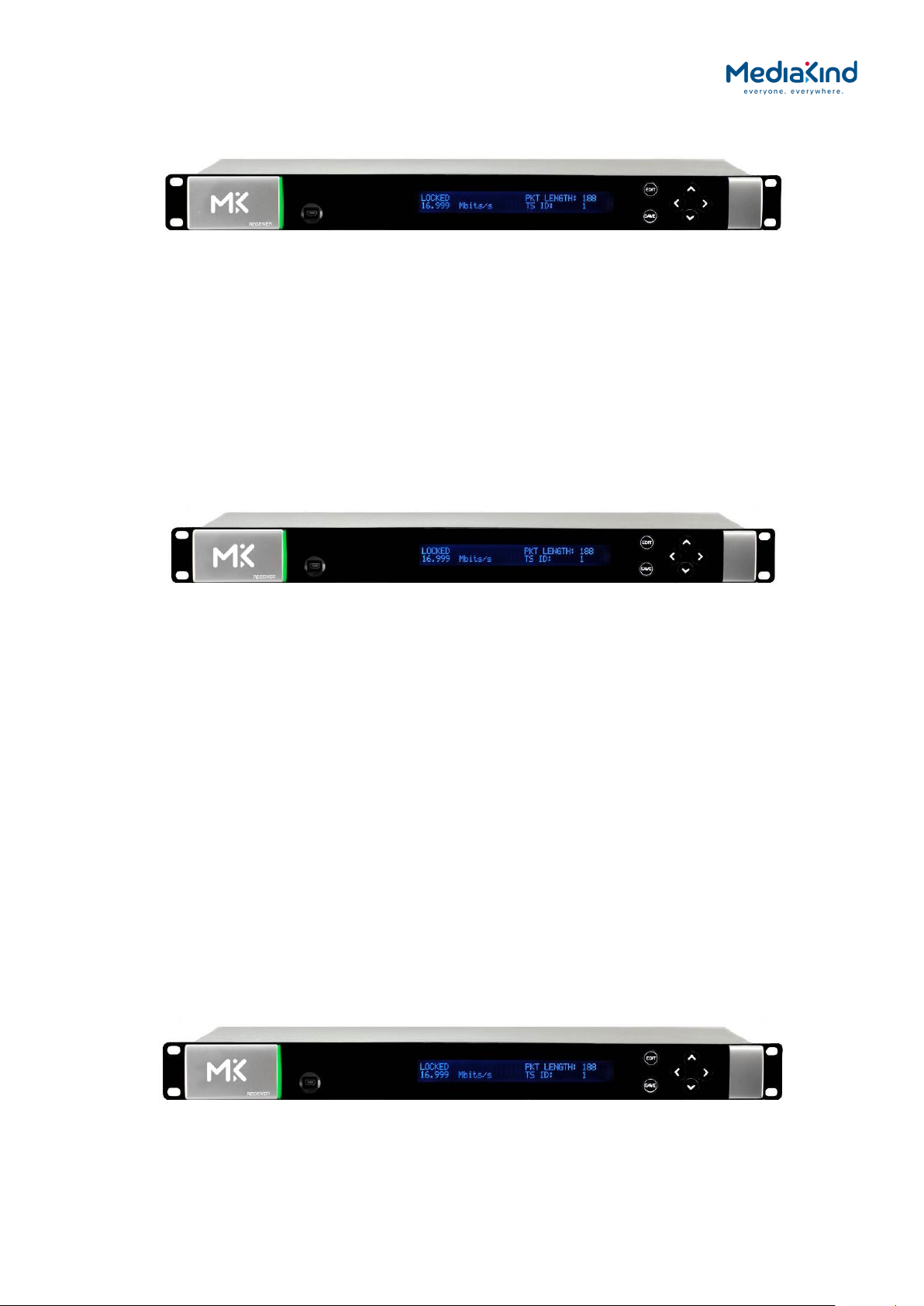
1.2.1.2. RX8200 Advanced Modular Receiver
Figure 1.1 RX8200 Advanced Modular Receiver
The advanced modular design of the RX8200 enables many
configuration possibilities allowing it to cover a broad range of
applications. It can be tailored to your precise needs, resulting in
a unit with only those features that are necessary without the additional
expense of superfluous functionality or connectivity.
The RX8200 can be tailored to standard definition or high definition
uses with MPEG-2, MPEG-4 or HEVC decode technology in both 4:2:0
and 4:2:2 modes as well as JPEG-2000. Connectivity into the receiver is
achieved with DVB-S2 satellite, DVB-S2 Extensions (DVB-S2X), IP and
ASI options.
The high powered processing capabilities of the RX8200 enable the unit
to be simply and easily upgraded in the field with additional software
options to increment the functionality at any point after initial
installation.
1.2.2. RX8300 Distribution Receivers
The RX8300 Distribution Receivers provide off the shelf model functionality designed to provide a
cost conscious unit to fit specific market areas / use case. For example the RX8320 is specifically
designed for 8VSB distribution applications and offers a set of targeted features specifically for
this market.
These basic market focused products can be customized to add extra functionality as required by
the broadcaster, however they do not allow the same level of customization that is offered by
the RX8200 flexible platform.
1.2.2.1. RX8310 Distribution Receiver
Figure 1.2 RX8310 Distribution Receiver
The RX8310 combines a DVB-S2 demodulator with MediaKind’s Director secure content delivery
and over-air receiver control solution as a standard feature.
The RX8310 provides the option to decrypt multiple services, allowing decryption of a complete
multiplex of channels with a single unit.
Single-service decoding options for MPEG-2 and MPEG-4 AVC 4:2:0 SD video, and HD service
down-conversion means the RX8310 can provide a simple and cost-effective route to hand-off
video into an analog network or for service monitoring.
RX8000 Integrated Receiver/Decoders
1553-FGB-101 759 Uen K
www.mediakind.com
1-14
1.2.2.2. RX8315 Distribution Receiver
Figure 1.3 RX8315 Distribution Receiver
The RX8315 enables video distribution for both analog and digital networks.
The RX8315 provides compatibility with DVB Common Interface CA systems, offering both single
service and multi-service decryption capability. Decrypted transport streams can be handed off
into digital networks through a choice of ASI or IP output interfaces.
The RX8315 can optionally decode any MPEG-2 or MPEG-4 AVC 4:2:0 video standard,
down-converting from HD to SD where necessary to provide an SD composite video output for
interfacing to analog networks or for low cost monitoring.
1.2.2.3. RX8320 ATSC Broadcast Receiver
Figure 1.4 RX8320 ATSC Broadcast Receiver
The RX8320 is specifically designed to enable a simple, reliable solution to the ATSC broadcast
transition for cable, telco or satellite operators who re-transmit the local broadcast channels.
The RX8320 provides both ASI and 8-VSB inputs for reception of the broadcast services over
terrestrial or fiber links. It then provides a pass-thru capability so that operators can carry the
digital signals all the way to a subscriber’s home.
To support analog TV delivery, the RX8320 also provides video decode capability with high
quality composite output and audio decode capability, including 5.1 multi-channel to stereo
down-mixing, to allow easy interfacing into the existing infrastructure.
High Definition (HDTV) digital TV services can be down-converted for analog SD delivery.
Automatic picture aspect ratio conversion is performed based on any active format description
(AFD) and bar data present on the incoming digital TV service.
Legal and regulatory requirements are also fulfilled by the RX8320 for the transition of ATSC
broadcast services into analog TV delivery, with the extraction and insertion of Closed Captions,
Nielsen data, TV Guide data, and V-Chip program rating information into the analog video
outputs.
1.2.2.4. RX8330 Distribution Receiver
Figure 1.5 RX8330 Distribution Receiver
The RX8330 provides feature-rich multi-format standard definition (SD) decoding capability with
high quality SDI output for video distribution applications.
RX8000 Integrated Receiver/Decoders
1553-FGB-101 759 Uen K
www.mediakind.com
1-15
RIGHT
LED
UP
LEFT
EDIT
The RX8330 gives the user access to the latest compression and transmission technologies to
allow for the most cost-effective and bandwidth transmissions possible while ensuring the
highest standards of reliability and video quality.
The RX8330 offers both ASI and DVB-S2 satellite input interfaces.
As security of content is always of paramount importance, compatibility with popular CA systems
including DVB Common Interface is provided.
The RX8330 allows multi-format decoding of all SD 4:2:0 video standards for high quality SDI
digital video and analog video outputs. This capability is further enhanced by the RX8330’s
ability to receive, and down-convert HD video to SD providing an SD output for broadcast or
monitoring.
Additionally, for systems that stay in the compressed domain, decrypted transport streams can
be handed off into digital networks through a choice of both ASI or optional IP output interfaces.
1.3. Construction
The RX8000 Receiver is constructed using a screened self-ventilated modular system. All
operational inputs and outputs are via rear-panel connectors. The unit may be operated
freestanding or mounted in a 19-inch rack.
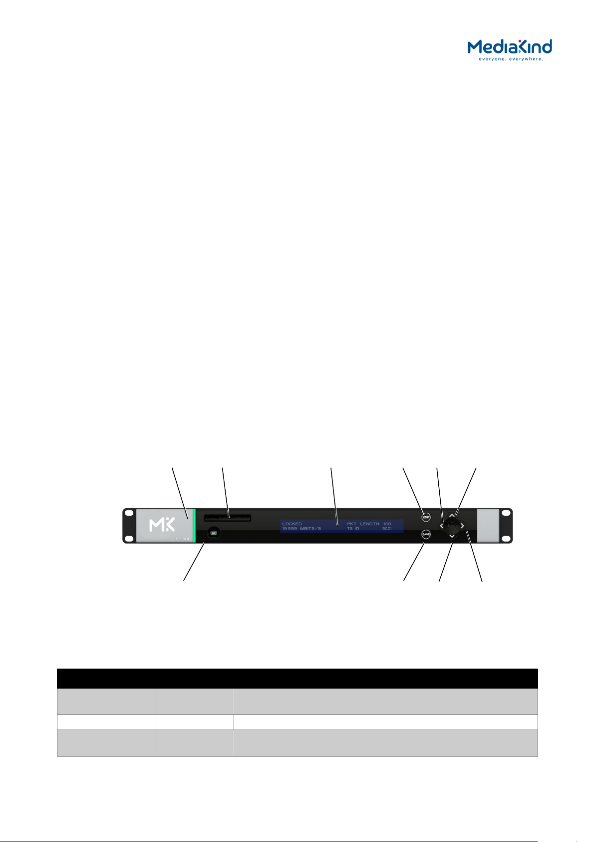
1.4. Front Panel
The user interface for the Front Panel consists of an alphanumeric Liquid Crystal Display,
pushbuttons and a status LED that are used to set-up, control and monitor the unit.
Various menu screens can be navigated on the LCD using the pushbuttons, which allow you to
select and modify key parameters and features of the unit.
Full details of the front panel menus and information on the use of these controls is given in
Chapter 3, Front Panel Control.
Status
USB Connector
(Servicing Only)
Figure 1.6 Front Panel Controls (RX8200)
CA Slot
Table 1.11 Front Panel Controls
LCD
SAVE
DOWN
Item Color Description
CA Slot - Conditional Access Slot. Located on front panel of RX8200 and
rear panel of RX8315 and RX8330.
USB Connector - This connector is for factory / service use only.
Status LED Red
RX8000 Integrated Receiver/Decoders
1553-FGB-101 759 Uen K
www.mediakind.com
CRITICAL Error. Indicates that a primary interface has lost
lock with the Transport Stream.

1-16
Amber MAJOR or MINOR Error. Indicates that the unit is locked to a
Transport Stream but an error has been detected signifying
incorrect conditions or system functioning.
Green NO Errors. Indicates that the unit is locked to a Transport
Stream and correct conditions and system functioning are
detected.
LCD - 2-line x 40-character back-lit dot-matrix Liquid Crystal Display
(LCD).
Edit - This pushbutton enables you to edit the parameters on the
selected LCD menu. Press again to exit without saving any
changes. Integral LED lit when functional.
Save - This pushbutton enables you to save any modified parameters
on the selected LCD menu. Integral LED lit when functional.
Up
Down
Left (Back)
Right (Forward)
- Navigation pushbuttons for selecting relevant LCD menu or for
incrementing / decrementing selected parameter values.
Integral LED lit when functional.
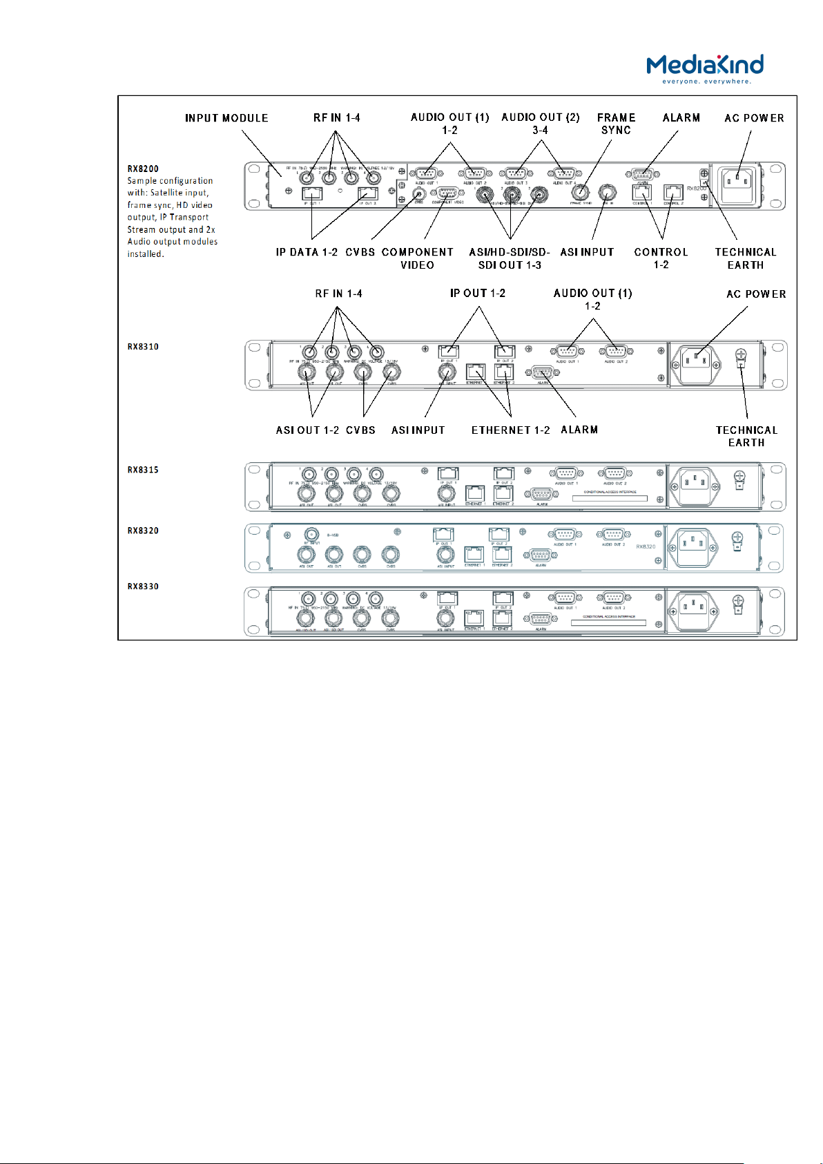
1.5. Rear Panels
All inputs, outputs and control connections are taken via the rear panel. Due to the modular
nature of these units, factory fitted hardware modules with different connections can be fitted to
any unit and therefore only a typical (sample) rear panel images are shown below.
Full details of the connectors for ALL base models and options are given in Chapter 2, Installing
the Equipment.
RX8000 Integrated Receiver/Decoders
1553-FGB-101 759 Uen K
www.mediakind.com
1-17
Figure 1.7 Rear Panels
RX8000 Integrated Receiver/Decoders
1553-FGB-101 759 Uen K
www.mediakind.com

1-18
Table 1.12 Rear Panels
Item Type Description
RF IN 1-4 F-type 75 Ω Radio Frequency (L-band) input.
ASI OUT 1-2
ASI/SDI OUT
ASI/HD-SDI/SD-SDI
OUT
ASI/3G-SDI/HD-
SDI/SD-SDI OUT
CVBS BNC 75 Ω Composite Video output.
ASI INPUT BNC 75 Ω Asynchronous Serial Interface input.
SVGA OUTPUT 15-way D-
IP DATA 1-2 RJ-45 IP Output card supports 1000BaseT Ethernet
ETHERNET 1-2
CONTROL 1-2
ALARM
ALARM RELAY
AUDIO OUT 1-2 9-way D-type
CA INTERFACE Card Slot A single slot allows the insertion of a
AC POWER IEC 100-240 V AC power input.
TECHNICAL EARTH Spade
BNC 75 Ω ASI = Asynchronous Serial Interface.
SDI = Serial Digital Interface.
SD-SDI = Standard Definition SDI.
HD-SDI = High Definition SDI.
3G-SDI = 2.970 Gbps serial link required for
1080P support.
Streaming data format that carries the MPEG
Transport Stream.
Component Video output (RGB/HV (SVGA) or
type
RJ-45 10-100BaseT control port for HTTP and FTP
9-way D-type
terminal
YPrPb).
transmission of encapsulated transport
stream
control of the RX8000.
A summary ALARM relay provides contact
closure when the unit detects an alarm, or
the power is switched off.
Each connector carries a single channel of a
stereo pair in both analogue and balanced
digital form.
Conditional Access Module (CAM) for
Common Interface support. On the RX8330C
this will be replaced with a smartcard slot.
Unit earthing connector.
1.6. Serial Number Identification
Beginning in 2014, MediaKind began a process of transitioning from numeric serial numbers to
an alphanumeric scheme. As part of this process, all receivers will display the serial number
using the new format.
For further details on the serial number scheme used, contact MediaKind Customer Services.
1.6.1. Chassis Ident SN
The Chassis Ident SN can be found printed on the left side panel of the RX8000 unit towards
the rear panel. It can also be found in the web browser interface under the Device Info Tab in
the Device Info > Unit Chassis Ident section.
This uniquely identifies the RX8000 unit and is the serial number that should be used in all cases
when communicating with MediaKind Customer Services so that it can be tracked. All
components fitted to your RX8000 unit will be tied to the Chassis Ident SN.
Refer to Chapter 3 on how to use the web browser interface.
RX8000 Integrated Receiver/Decoders
1553-FGB-101 759 Uen K
www.mediakind.com

1-19
1.6.2. Board Serial Number
The Board Serial Number can be found in the web browser interface under the Device Info Tab
in the Device Info > Modules section. The Board Serial Number will be listed in the RX8000
row (Board Type 1900) under the Serial Number column.
Refer to Chapter 3 on how to use the web browser interface.
1.6.3. Customization Serial Number
The Customization Serial Number can be found in the web browser interface under the
Customization Tab in the Customization > Parameters > Serial Number section. This
number should be used when Custom Keys or License Keys need to be activated.
Refer to Chapter 3 on how to use the web browser interface.
1.6.4. Unique Hardware ID
The Unique Hardware ID is a unique identifier used for addressing the receiver in an
MediaKind Director system. It is the same as the Customization Serial Number described above.
RX8000 Integrated Receiver/Decoders
1553-FGB-101 759 Uen K
www.mediakind.com

2-1
2. Installing the Equipment
Contents
2.1. Read This First! ......................................................................... 2-2
2.2. Mounting and Ventilation ........................................................... 2-2
2.2.1. Fixing and Rack Mounting .......................................................... 2-2
2.2.2. Ventilation ............................................................................... 2-2
2.2.2.1. Openings in the Covers .............................................................. 2-2
2.3. Signal Connections .................................................................... 2-3
2.3.1. General.................................................................................... 2-3
2.3.2. RF IN Connector ....................................................................... 2-4
2.3.3. IP IN Connector (RX8200 only) ................................................... 2-4
2.3.4. G.703 Connector (RX8200 only) ................................................. 2-5
2.3.5. DVB-T2 (OFDM) Connector (RX8200 only) ................................... 2-5
2.3.6. ASI OUT Connector (RX8310/15/20 only) .................................... 2-5
2.3.7. ASI/SDI OUT Connector ............................................................. 2-6
2.3.8. ASI/HD-SDI/SD-SDI OUT Connector (RX8200 only) ...................... 2-6
2.3.9. CVBS Connector........................................................................ 2-6
2.3.10. AUDIO/AUDIO OUT Connector .................................................... 2-7
2.3.11. ETHERNET/CONTROL Connector .................................................. 2-7
2.3.12. IP DATA Connector .................................................................... 2-8
2.3.13. ASI IN Connector ...................................................................... 2-8
2.3.14. COMPONENT VIDEO Connector (RX8200 only) .............................. 2-9
2.3.15. DATA OUT Connector (RX8200 only) ......................................... 2-10
2.3.16. ALARM Connector .................................................................... 2-10
2.3.17. RS232/RS485 REMOTE Connector (RX8200 only) ........................ 2-11
List of Figures
Figure 2.1 Air-flow through the Equipment .................................................. 2-2
Figure 2.2 Rear Panels .............................................................................. 2-3
List of Tables
Table 2-1 RF IN Connector ........................................................................... 2-4
Table 2-2 IP IN Connector............................................................................ 2-4
Table 2-3 G.703 Connector .......................................................................... 2-5
Table 2-4 DVB-T2 Connector ........................................................................ 2-5
Table 2-5 ASI OUT Connector ....................................................................... 2-5
Table 2-6 ASI/SDI OUT Connector ................................................................ 2-6
Table 2-7 ASI/HD-SDI/SD-SDI OUT Connector ............................................... 2-6
Table 2-8 CVBS Connector ........................................................................... 2-6
Table 2-9 AUDIO/AUDIO OUT Connectors ...................................................... 2-7
Table 2-10 ETHERNET/CONTROL Connector ................................................... 2-7
Table 2-11 IP DATA Connector ..................................................................... 2-8
Table 2-12 ASI IN Connector ........................................................................ 2-8
RX8000 Integrated Receiver/Decoders
1553-FGB 101 759 Uen K
www.mediakind.com

2-2
Table 2-13 COMPONENT VIDEO Connector ..................................................... 2-9
Table 2-14 DATA OUT Connector ................................................................ 2-10
Table 2-15 ALARM Connector ..................................................................... 2-10
Table 2-16 RS232/RS485 REMOTE Connector ............................................... 2-11
2.1. Read This First!
Please refer to the Installation, Safety and Compliance Information for MediaKind Compression
Products Reference Guide supplied with your product for full details of installation requirements.
This guide only contains additional product specific information where required.
2.2. Mounting and Ventilation
2.2.1. Fixing and Rack Mounting
The equipment is designed for fixed use only and has been shipped with fixing brackets suitable
for a standard 19-inch rack. When installed in a rack, it should be secured using the fixing
brackets. In addition, support shelves must be used to reduce the weight on the brackets.
Ensure it is firmly and safely located and it has an adequate flow of free-air.
Slide the receiver onto the chassis supports and affix to the rack by means of an M6 x 18 mm
Pan Head screw in each corner.
A freestanding unit should be installed on a secure horizontal surface where it is unlikely to be
knocked or its connectors and leads disturbed.
2.2.2. Ventilation
2.2.2.1. Openings in the Covers
Side openings in the unit, as well as side-mounted cooling fans, are provided for ventilation.
They ensure reliable operation of the product and protect it from overheating. The openings of
the fans must not be blocked or covered.
Fans are
mounted on
this side of
the unit
Air is
released
through
vents at
the side of
the unit
Figure 2.1 Air-flow through the Equipment
RX8000 Integrated Receiver/Decoders
1553-FGB 101 759 Uen K
www.mediakind.com

2-3
2.3. Signal Connections
2.3.1. General
CAUTION: It is strongly recommended that the terminal marked at the rear panel of
the equipment is connected to a site Technical Earth before any external
connections are made and the equipment is powered. This limits the migration of
stray charges.
All signal connections are made via the rear panel. A typical rear panel is shown in Figure 2.2.
Full technical specifications for the connections are given in Annex B. The Receiver provides a
flexible Transport Stream input interface. The status information appropriate to each input type
is available to the User via the User Interface, and also via the remote control interfaces.
RX8000 Integrated Receiver/Decoders
1553-FGB 101 759 Uen K
www.mediakind.com
Figure 2.2 Rear Panels

2-4
2.3.2. RF IN Connector
Up to four RF inputs connect the L-band output of a suitable Low-Noise Block down-converter
(LNB) to the unit either directly or via a suitable attenuator. The RF inputs may also be used to
supply DC power to the LNB, if required.
CAUTION: The receiver provides DC power via the active L-band input connector to drive
an LNB. Do not connect equipment other than an LNB to this connector.
Failure to do this may result in damage to the external equipment.
The F-type connector is not suitable for repeated connection and disconnection.
When intended for use in this way, fit a sacrificial connector and connect to it.
Table 2-1 RF IN Connector
Item Specification
Connector type F-Type 75 Ω female socket
Connector designation RF IN 1
RF IN 2
RF IN 3
RF IN 4
LNB power supply See Caution above.
Pin-outs Centre
Shield
Input
Ground/Chassis
2.3.3. IP IN Connector (RX8200 only)
Units can provide two input Ethernet data interfaces.
Table 2-2 IP IN Connector
Item Specification
Connector type RJ-45
Connector
designation
Pin
IP IN 1
IP IN 2
RF IN
IP IN
Pin-outs Pin 1
Pin 2
Pin 3
Pin 4
Pin 5
Pin 6
Pin 7
Pin 8
Tx Out (+)
Tx Out (-)
Rx In (+)
CMT
CMT
Rx In (-)
CMT
CMT
RX8000 Integrated Receiver/Decoders
1553-FGB 101 759 Uen K
www.mediakind.com

2-5
2.3.4. G.703 Connector (RX8200 only)
The unit provides a single G.703 input connector.
Table 2-3 G.703 Connector
Item Specification
Connector type BNC 75 Ω female socket
Connector designation G.703 E3/DS-3
Pin-outs Centre
Shield
Input
Ground/Chassis
2.3.5. DVB-T2 (OFDM) Connector (RX8200 only)
The unit provides a single DVB-T2 input connector.
Table 2-4 DVB-T2 Connector
Item Specification
Connector type F-Type 75 Ω female socket
Connector designation DVT-T/T2
Pin-outs Centre
Shield
Input
Ground/Chassis
G.703 IN
T2 IN
2.3.6. ASI OUT Connector (RX8310/15/20 only)
The unit provides two coaxial ASI digital outputs depending on the user selectable configuration.
Table 2-5 ASI OUT Connector
Item Specification
Connector type BNC 75 Ω female socket
Connector designation ASI OUT 1
ASI OUT 2
Pin-outs Centre
Shield
Output
Ground/Chassis
ASI OUT
RX8000 Integrated Receiver/Decoders
1553-FGB 101 759 Uen K
www.mediakind.com
2-6
2.3.7. ASI/SDI OUT Connector
The unit provides two coaxial ASI/SDI outputs depending on the user selectable configuration.
Table 2-6 ASI/SDI OUT Connector
Item Specification
Connector type BNC 75 Ω female socket
Connector designation ASI/SDI OUT 1
ASI/SDI OUT 2
Pin-outs Centre
Shield
Output
Ground/Chassis
ASI/SDI OUT
2.3.8. ASI/HD-SDI/SD-SDI OUT Connector (RX8200 only)
The unit provides three coaxial ASI/HD-SDI/SD-SDI outputs depending on the user selectable
configuration. Where applicable, these connectors are also used for 3G-SDI output.
Table 2-7 ASI/HD-SDI/SD-SDI OUT Connector
Item Specification
Connector type BNC 75 Ω female socket
Connector designation
ASI/HD-SDI/SD-SDI OUT
1
ASI/HD-SDI/SD-SDI OUT
2
ASI/HD-SDI/SD-SDI OUT
3
Pin-outs Centre
Shield
Output
Ground/Chassis
ASI/HD-SDI/SD-SDI OUT
2.3.9. CVBS Connector
A coaxial socket provides composite video outputs supporting NTSC(M) (with and without
pedestal) and PAL(B,D,H,I,M).
Table 2-8 CVBS Connector
Item Specification
Connector type BNC 75 Ω female socket
Connector designation CVBS1
CVBS2 (RX83xx only)
Pin-outs Centre
Shield
Output
Ground/Chassis
RX8000 Integrated Receiver/Decoders
1553-FGB 101 759 Uen K
www.mediakind.com
CVBS

2-7
2.3.10. AUDIO/AUDIO OUT Connector
All units provide a pair of connectors supplying two stereo channels. Each carries a single
channel stereo pair in both analogue and balanced digital form.
Table 2-9 AUDIO/AUDIO OUT Connectors
Item Specification
Connector type 9-way D-type, male
Connector
designation
AUDIO OUT 1
AUDIO OUT 2
AUDIO 3 (RX8200 only)
AUDIO 4 (RX8200 only)
Pin
Pin-outs Pin 1
Pin 2
Pin 3
Pin 4
Pin 5
Pin 6
Pin 7
Pin 8
Pin 9
Nominal output
50 Ω
Digital audio +
Ground
Left +
Right +
Ground
Digital audio –
Ground
Left –
Right –
impedance
Maximum data
3.072 Mbps
rate
Analogue Output
level
+20 dBm nominal clipping level.
Selectable in range 12 to +24 dBm.
Load impedance ≥600 Ω balanced
AUDIO/AUDIO OUT
2.3.11. ETHERNET/CONTROL Connector
All units provide two Ethernet remote control interfaces for Web Browser Control.
Table 2-10 ETHERNET/CONTROL Connector
Item Specification
Connector type RJ-45
Connector
designation
ETHERNET 1 or CONTROL 1
ETHERNET 2 or CONTROL 2
Pin
Pin-outs Pin 1
Pin 2
Pin 3
Pin 4
Pin 5
Pin 6
Pin 7
Pin 8
RX8000 Integrated Receiver/Decoders
1553-FGB 101 759 Uen K
www.mediakind.com
Tx Out (+)
Tx Out (-)
Rx In (+)
NC
NC
Rx In (-)
NC
NC
ETHERNET CONTROL

2-8
2.3.12. IP DATA Connector
Units can provide two Ethernet data interfaces.
Table 2-11 IP DATA Connector
Item Specification
Connector type RJ-45
Connector
designation
IP DATA 1
IP DATA 2
IP DATA
Pin
Pin-outs Pin 1
Pin 2
Pin 3
Pin 4
Pin 5
Pin 6
Pin 7
Pin 8
Tx Out (+)
Tx Out (-)
Rx In (+)
CMT
CMT
Rx In (-)
CMT
CMT
2.3.13. ASI IN Connector
The unit provides an ASI input socket for detection of the transport stream lock on the ASI input.
Table 2-12 ASI IN Connector
Item Specification
Connector type BNC 75 Ω female socket
Connector designation ASI IN
Pin-outs Centre
Shield
Input
Ground/Chassis
ASI IN
RX8000 Integrated Receiver/Decoders
1553-FGB 101 759 Uen K
www.mediakind.com
2-9
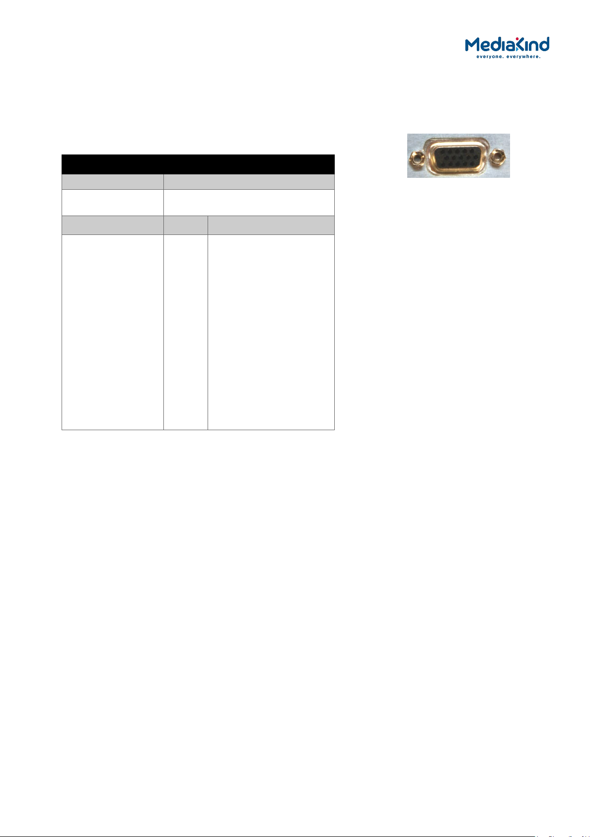
2.3.14. COMPONENT VIDEO Connector (RX8200 only)
The equipment is equipped with a SVGA 15-pin D-type connector for video output monitoring in
the standard configuration. The SVGA connector shall be set to RGB/HV (SVGA) or YPrPb under
control of the User interface and remote control interfaces.
Table 2-13 COMPONENT VIDEO Connector
Item Specification
Connector type 15-way D-type, female
Connector
COMPONENT VIDEO
designation
Pin
Pin-outs Pin 1
Pin 2
Pin 3
Pin 4
Pin 5
Pin 6
Pin 7
Pin 8
Pin 9
Pin 10
Pin 11
Pin 12
Pin 13
Pin 14
Pin 15
Red / Pr, 75 Ω, 0,7Vt-t
Green / Y, 75 Ω, 0,7Vt-t
Blue / Pb, 75 Ω, 0,7Vt-t
NC
Video GND
Red GND
Green GND
Blue GND
NC
Sync GND
NC
NC
H-Sync
V-Sync
NC
COMPONENT VIDEO
RX8000 Integrated Receiver/Decoders
1553-FGB 101 759 Uen K
www.mediakind.com
2-10
2.3.15. DATA OUT Connector (RX8200 only)
A data output interface may be used with either RS232 or RS422 connector, as described below.
Table 2-14 DATA OUT Connector
Item Specification
Connector type 9-way, D-type, male
Connector
DATA OUT
DATA OUT
designation
Pin RS232 RS485
Pin-outs Pin 1
Pin 2
Pin 3
Pin 4
Pin 5
Pin 6
Pin 7
Pin 8
Pin 9
NC
TxD
RxD
NC
NC
NC
CTS
(RTS)
NC
HSD_CLK_A
NC
NC
NC
NC
HSD_CLK_B
NC
HSD_DATA_A
HSD_DATA_B
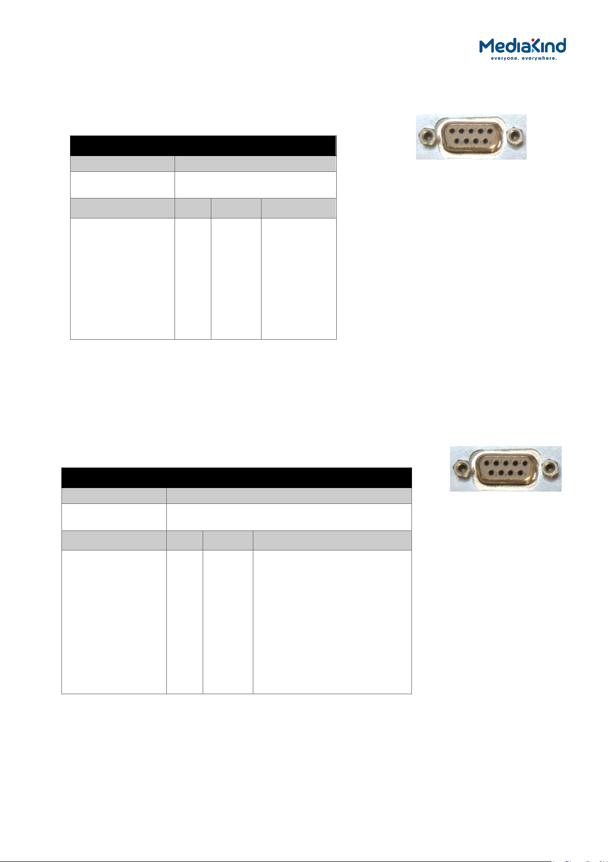
2.3.16. ALARM Connector
All units provide an alarm relay connector supplying a summary relay. Under user configuration,
it is activated whenever the unit detects an alarm, or the power is switched off.
The table below shows the pin-out applicable to Software Version 5.12.0 onwards, or when the
Relay Mode is set to Revised in Software Version 5.16.0 onwards.
Table 2-15 ALARM Connector
Item Specification
Connector type 9-way, D-type, female
Connector
ALARM
designation
Pin Relay Connection
Pin-outs Pin 1
Pin 2
Pin 3
Pin 4
Pin 5
Pin 6
Pin 7
Pin 8
Pin 9
3
2
3
1
3
2
2
1
1
Normally Closed
Common
Common
Common
Normally Open
Normally ClosedNormally Open
Normally Closed (Closed on
Alarm)
Normally Open (Open On
Alarm)
ALARM
RX8000 Integrated Receiver/Decoders
1553-FGB 101 759 Uen K
www.mediakind.com
2-11
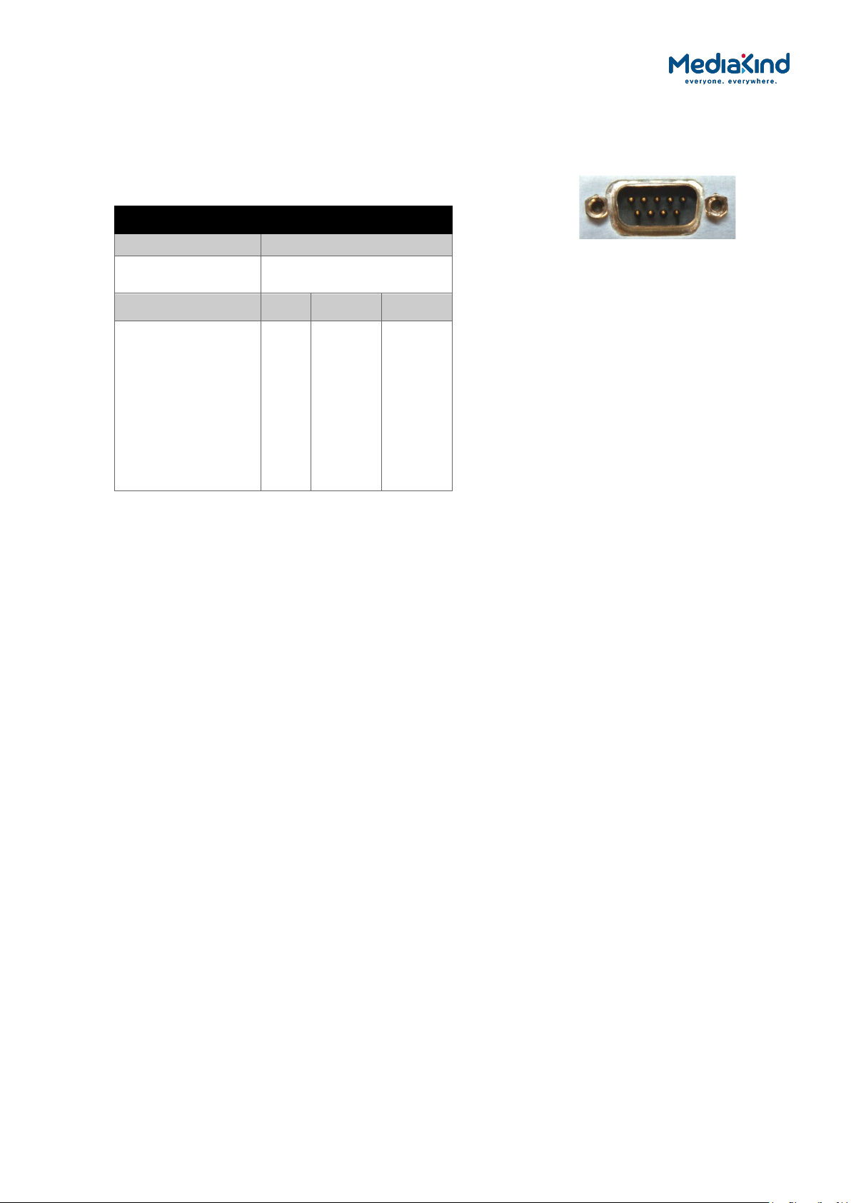
2.3.17. RS232/RS485 REMOTE Connector (RX8200 only)
A remote control interface may be used with either RS232 or RS485 connector, as detailed
below.
Table 2-16 RS232/RS485 REMOTE Connector
Item Specification
Connector type 9-way, D-type, male
Connector
RS232/RS485 REMOTE
designation
Pin RS232 RS485
Pin-outs Pin 1
Pin 2
Pin 3
Pin 4
Pin 5
Pin 6
Pin 7
Pin 8
Pin 9
DCD
RxD
TxD
DTR
Ground
DSR
RTS
CTS
RI
NC
NC
NC
RxD+
NC
TxDTxD+
RXDNC
RS232/RX485
RX8000 Integrated Receiver/Decoders
1553-FGB 101 759 Uen K
www.mediakind.com

3–1
3. Using the Equipment
Contents
3.1. Introduction ............................................................... 3–10
3.2. Powering the Equipment .............................................. 3–10
3.3. Using the Front Panel .................................................. 3–10
3.3.1. USB Connector ........................................................... 3–11
3.3.2. Status LED ................................................................. 3–11
3.3.3. LCD .......................................................................... 3–11
3.3.4. Arrow Pushbuttons (Up, Down, Left, Right) .................... 3–11
3.3.5. Edit and Save Pushbuttons ........................................... 3–11
3.3.6. Menu Structure ........................................................... 3–12
3.4. Using the Web Browser ............................................... 3–18
3.4.1. Setting Up Web Browser Remote Control ....................... 3–18
3.4.2. XPO Password Protection ............................................. 3–19
3.4.3. Using the Web Browser Interface in Dashboard View ....... 3–21
3.4.4. Using the Web Browser Interface in Advanced View ........ 3–25
3.5. SNMP ........................................................................ 3–28
3.5.1. Setting Up SNMP Remote Control .................................. 3–28
3.5.2. Downloading the MIB .................................................. 3–30
3.6. Director ..................................................................... 3–30
3.6.1. Setting up Director Remote Control ............................... 3–30
3.6.2. Over-Air Control (OAC) Lockout .................................... 3–30
3.7. RS232/485 RCP .......................................................... 3–31
3.8. Local Control Lockout .................................................. 3–31
3.9. General Web Browser Pages ......................................... 3–31
3.9.1. Status ....................................................................... 3–31
3.9.2. Device Info ................................................................ 3–33
3.9.3. Alarms ...................................................................... 3–43
3.9.4. Customization ............................................................ 3–64
3.9.5. Presets ...................................................................... 3–66
3.9.6. Save/Load ................................................................. 3–67
3.9.7. Help .......................................................................... 3–70
3.10. Inputs ....................................................................... 3–71
3.10.1. Availability ................................................................. 3–71
3.10.2. ASI ........................................................................... 3–77
3.10.3. Satellite ..................................................................... 3–78
3.10.4. 100/1000BaseT IP Input .............................................. 3–91
3.10.5. G.703 ...................................................................... 3–117
3.10.6. DVB-T/T2 (OFDM) ..................................................... 3–126
3.10.7. ATSC 8 VSB Digital Terrestrial Input ............................ 3–149
3.11. Conditional Access .................................................... 3–152
3.11.1. General CA Status..................................................... 3–152
3.11.2. Common Interface .................................................... 3–154
3.11.3. BISS ....................................................................... 3–161
3.11.4. Director ................................................................... 3–167
3.11.5. RAS ........................................................................ 3–182
3.11.6. Embedded NDS CA (BSkyB) ....................................... 3–184
3.11.7. Embedded NDS CA (Sky Italia) ................................... 3–189
RX8000 Integrated Receiver/Decoders
1553-FGB 101 759 Uen K
www.mediakind.com

3–2
3.11.8. Signal Protection....................................................... 3–193
3.11.9. DVB-S2 Gold Codes................................................... 3–195
3.12. Services .................................................................. 3–197
3.12.1. Service Selection ...................................................... 3–197
3.13. Video Selection and Control ....................................... 3–205
3.13.1. Video Configuration ................................................... 3–205
3.13.2. Video Formats Supported ........................................... 3–215
3.13.3. Ultra HD (4K) Contribution Support ............................. 3–220
3.13.4. Video Conversion ...................................................... 3–223
3.13.5. Receiver Delay ......................................................... 3–233
3.13.6. Test Patterns ............................................................ 3–238
3.13.7. Video Standards Control ............................................ 3–240
3.13.8. Fail Modes ............................................................... 3–245
3.13.9. Frame Sync .............................................................. 3–247
3.14. Audio Selection and Control ....................................... 3–250
3.14.1. Audio Decoders Present ............................................. 3–250
3.14.2. Audio Output Options ................................................ 3–251
3.14.3. Audio Formats Supported .......................................... 3–252
3.14.4. Audio Configuration Options ....................................... 3–254
3.14.5. Front Panel Audio Selection and Control ....................... 3–265
3.15. Audio Channel Configuration Modes ............................ 3–269
3.15.1. Audio Formats Supported by the Channel Configuration Modes
.............................................................................. 3–269
3.15.2. Channel Configuration: Stereo Pairs ............................ 3–270
3.15.3. Channel Configuration: Multi-Channel (5.1).................. 3–272
3.15.4. Channel Configuration: Dual Multi-Channel (5.1) .......... 3–274
3.15.5. Channel Configuration: Phase Aligned Audio (PAA) ........ 3–276
3.15.6. Channel Configuration: Paired Decoder Mode ............... 3–280
3.15.7. Channel Configuration: 10-Stereo Pairs (MUSICAM only) Audio
.............................................................................. 3–286
3.15.8. Channel Configuration: 8 Channel AES3....................... 3–287
3.15.9. Channel Configuration: 16 Channel Aligned (MUSICAM only)
Audio ...................................................................... 3–289
3.16. Multi-Service Radio Decoder ....................................... 3–290
3.16.1. Radio Mode .............................................................. 3–291
3.17. Auxiliary Data .......................................................... 3–294
3.17.1. VBI and VANC Data ................................................... 3–294
3.17.2. Teletext ................................................................... 3–318
3.17.3. Subtitles .................................................................. 3–321
3.17.4. SCTE 35 Splice Message Decode Support ..................... 3–328
3.17.5. Cue Tone (DTMF) Splicing Support .............................. 3–338
3.17.6. Multi Protocol Encapsulation (MPE) Data ...................... 3–341
3.17.7. Low Speed Data ....................................................... 3–347
3.17.8. Remote Device Control .............................................. 3–351
3.18. Output Ports ............................................................ 3–353
3.18.1. Asynchronous Serial Interface (ASI) and Serial Digital
Interface (SDI) Output .............................................. 3–354
3.18.2. VGA Component Output ............................................. 3–356
3.18.3. IP Transport Stream Output ....................................... 3–357
3.19. Service Filtering and Service Splitting .......................... 3–365
3.19.1. Searching the Minimum Bit Rate When Service Filtering . 3–366
3.19.2. Configuration ........................................................... 3–367
RX8000 Integrated Receiver/Decoders
1553-FGB 101 759 Uen K
www.mediakind.com

3–3
3.19.3. Single Service Filtering .............................................. 3–371
3.19.4. Multi Service Filtering ................................................ 3–372
3.19.5. Remapping .............................................................. 3–375
3.19.6. Service Splitting ....................................................... 3–379
3.20. Miscellaneous Operations ........................................... 3–382
3.20.1. Front Panel Procedures .............................................. 3–382
3.20.2. Remote Procedures ................................................... 3–383
3.21. Install Software with Upgrade Utility ........................... 3–384
3.21.1. Compatibility ............................................................ 3–384
3.21.2. Installation .............................................................. 3–384
3.21.3. Quick User Guide ...................................................... 3–385
3.22. Ethernet Upgrading ................................................... 3–387
List of Figures
Figure 3-1 Front Panel Controls (RX8200) ..................................... 3–11
Figure 3-2 Front Panel Main Menu; Input, Output, Presets, Customization
Sub-menus ................................................................ 3–13
Figure 3-3 Sub-menu System ...................................................... 3–14
Figure 3-4 Sub-menu Service ...................................................... 3–15
Figure 3-5 Sub-menu Decode ...................................................... 3–16
Figure 3-6 Sub-menu VBI-VANC of Decode .................................... 3–17
Figure 3-7 Sub-menu Alarms ....................................................... 3–18
Figure 3-8 Windows Security ....................................................... 3–19
Figure 3-9 XPO Password Protection Settings ................................. 3–20
Figure 3-10 Example of the Dashboard View ................................... 3–22
Figure 3-11 C/N Margin Status Pane ............................................... 3–24
Figure 3-12 Example of Active Alarms from the Dashboard View ........ 3–25
Figure 3-13 Web Page Overview in Advanced View ........................... 3–26
Figure 3-14 About Dialog .............................................................. 3–27
Figure 3-15 SNMP Web Page ......................................................... 3–29
Figure 3-16 Status Web Page ........................................................ 3–32
Figure 3-17 Device Info Web Page ................................................. 3–33
Figure 3-18 Device Info > Build Web Page ...................................... 3–35
Figure 3-19 Device Info > Environment Web Page ........................... 3–36
Figure 3-20 Device Info > Network Settings Web Page ..................... 3–36
Figure 3-21 Device Info > Remote Control ...................................... 3–40
Figure 3-22 Device Info > Modules Web Page .................................. 3–41
Figure 3-23 Device Info > Trap Destination Table Web Page .............. 3–42
Figure 3-24 Trap Destination Table > Add Item Web Page................. 3–42
Figure 3-25 Configuring Alarm Behavior .......................................... 3–43
Figure 3-26 Alarm settings for Control Interface section .................... 3–44
Figure 3-27 Alarm settings for the Input section .............................. 3–45
Figure 3-28 Alarm settings for the Input > TS Monitor section ........... 3–46
Figure 3-29 Alarm settings for the Input > Satellite Input section
applicable to satellite board types 1911, 1928 and 1931 .. 3–46
Figure 3-30 Alarm settings for the Input > Satellite Input section
applicable to satellite board type 1935 .......................... 3–47
RX8000 Integrated Receiver/Decoders
1553-FGB 101 759 Uen K
www.mediakind.com

3–4
Figure 3-31 Alarm settings for the Input > IP Input section ............... 3–50
Figure 3-32 Alarm settings for the Input > IP Input section applicable
when RX8200/SWO/IP/IN/SEAMLESS option present ....... 3–54
Figure 3-33 Alarm settings for the Input > G.703 Input section ......... 3–55
Figure 3-34 Alarm settings for the Input > Terrestrial Input section ... 3–55
Figure 3-35 Alarm settings for the Input > 8VSB Input section .......... 3–56
Figure 3-36 Alarm settings for the Service > Conditional Access section 3–
57
Figure 3-37 Alarm settings for the Service > Video section ................ 3–57
Figure 3-38 Alarm settings for the Service > Audio section................ 3–58
Figure 3-39 Alarm settings for the Service > Auxiliary Data section .... 3–58
Figure 3-40 Alarm settings for the Service > 422 Decoder Card section . 3–
59
Figure 3-41 Alarm setting for Service > Down Converter Card section 3–60
Figure 3-42 Alarm settings for Output > SDI/CVBS section ............... 3–60
Figure 3-43 Alarm Settings for Output > IP Output section ................ 3–61
Figure 3-44 Alarm Settings for Output > Filtering section .................. 3–62
Figure 3-45 Alarm Settings for Environment Section ......................... 3–63
Figure 3-46 Using the Status page Clear button to clear the Base Decoder
Failure alarm .............................................................. 3–64
Figure 3-47 Customization Web Page ............................................. 3–65
Figure 3-48 Customization > Licensed Features Web Page ................ 3–65
Figure 3-49 Presets Web Page ....................................................... 3–66
Figure 3-50 Save Configuration...................................................... 3–67
Figure 3-51 Restore Configuration .................................................. 3–67
Figure 3-52 Extracting the MIB File ................................................ 3–68
Figure 3-53 Extracting the Alarm Log File ........................................ 3–68
Figure 3-54 Extracting the Splice Log File ........................................ 3–68
Figure 3-55 Extracting the Event Log File ........................................ 3–69
Figure 3-56 Extracting the Quality Log File ...................................... 3–69
Figure 3-57 Upgrading the IRD Software via the Web Interface ......... 3–70
Figure 3-58 Help Web Page ........................................................... 3–70
Figure 3-59 Overview of the Input page from the web interface (ASI and
Satellite input card fitted) ............................................ 3–72
Figure 3-60 Enabling Input Redundancy Mode ................................. 3–73
Figure 3-61 Configuration setting for Input Redundancy section ......... 3–74
Figure 3-62 Configuration settings for the Input > Null Packet Override
section ...................................................................... 3–75
Figure 3-63 Configuration settings for the Input > TS Monitor section 3–75
Figure 3-64 Selecting services for the TS Monitor using the Service plus
page ......................................................................... 3–76
Figure 3-65 Input > Configuration RF#1 Web Page .......................... 3–80
Figure 3-66 Input > SAT Input Web Page ........................................ 3–88
Figure 3-67 The Protocol Stack ...................................................... 3–93
Figure 3-68 Building the Ethernet Frame ......................................... 3–93
Figure 3-69 Application example of how SMPTE 2022-7 is used.......... 3–95
Figure 3-70 IP Input Status ........................................................... 3–96
Figure 3-71 IP Interface Parameters ............................................... 3–99
Figure 3-72 Card Config Settings ................................................... 3–99
Figure 3-73 IP Input Stream Setup .............................................. 3–100
RX8000 Integrated Receiver/Decoders
1553-FGB 101 759 Uen K
www.mediakind.com

3–5
Figure 3-74 IP Message from Webpage Dialog ............................... 3–101
Figure 3-75 Avoiding conflicts between the Input Redundancy Mode engine
and the IP Input Redundancy engine ........................... 3–102
Figure 3-76 IP Redundancy Configuration ..................................... 3–103
Figure 3-77 IP Multicast Redundancy State Diagram ....................... 3–104
Figure 3-78 Input Web Page (G.703 ATM Input Card Fitted) ............ 3–119
Figure 3-79 Input > G.703 Input Web Page ................................... 3–120
Figure 3-80 Basic Configuration GUI ............................................. 3–127
Figure 3-81 Advanced Configuration ............................................. 3–129
Figure 3-82 Status Display (Receiving a DVB-T Stream) ................. 3–131
Figure 3-83 Status Display(Receiving a DVB-T2 Stream) ................. 3–131
Figure 3-84 Advanced Status if Receiving a DVB-T Stream .............. 3–135
Figure 3-85 Advanced Status if Receiving a DVB-T2 Stream ............ 3–135
Figure 3-86 Input (ATSC 8 VSB Digital Terrestrial Input) Web Page .. 3–150
Figure 3-87 CA Service Status Web Page ...................................... 3–152
Figure 3-88 Single Service Common Interface ............................... 3–156
Figure 3-89 CAM Insertion .......................................................... 3–157
Figure 3-90 Service plus Interface ................................................ 3–157
Figure 3-91 Common Interface Components .................................. 3–158
Figure 3-92 Location of BISS Key ................................................. 3–162
Figure 3-93 Location of User One and User Two IDs ....................... 3–163
Figure 3-94 BISS Configuration Within the Web Interface ............... 3–164
Figure 3-95 Service plus Menu ..................................................... 3–165
Figure 3-96 Customization Serial Number Field .............................. 3–169
Figure 3-97 CA > Director ........................................................... 3–175
Figure 3-98 Download ................................................................ 3–176
Figure 3-99 Over Air Message Field .............................................. 3–178
Figure 3-100 DSNG Key Field ..................................................... 3–183
Figure 3-101 CA Web Page (NDS CA Card fitted) .......................... 3–185
Figure 3-102 CA Entitlement Page (NDS CA Card fitted) ................ 3–186
Figure 3-103 CA Web Page (NDS CA Card fitted) .......................... 3–190
Figure 3-104 CA Entitlement Page (NDS CA Card Fitted) ............... 3–191
Figure 3-105 Custom Key Field .................................................. 3–194
Figure 3-106 TTV Signal Protection Field ..................................... 3–194
Figure 3-107 Gold Sequence N Field ........................................... 3–196
Figure 3-108 Service plus Web Page ........................................... 3–197
Figure 3-109 Decode Web Page .................................................. 3–198
Figure 3-110 Decode > Advanced Web Page ................................ 3–199
Figure 3-111 Hunt Mode Operation ............................................. 3–200
Figure 3-112 Service Drop Operation .......................................... 3–201
Figure 3-113 Multi Service Drop Mode ......................................... 3–203
Figure 3-114 PMT Refresh Mode ................................................. 3–204
Figure 3-115 Video Configuration Under the Decode Web Page ...... 3–205
Figure 3-116 Advanced Video Features........................................ 3–211
Figure 3-117 RX8200 4K Configuration ....................................... 3–222
Figure 3-118 Down-conversion Quality Levels .............................. 3–225
Figure 1-119Down-conversion Grades ........................................... 3–226
Figure 3-120 Decode > Advanced Web Page ................................ 3–228
Figure 3-121 Output Web Page .................................................. 3–229
RX8000 Integrated Receiver/Decoders
1553-FGB 101 759 Uen K
www.mediakind.com

3–6
Figure 3-122 Decode Web Page with AFD/Bar Data Status ............. 3–231
Figure 3-123 Delay Fields .......................................................... 3–234
Figure 3-124 System Web Page.................................................. 3–237
Figure 3-125 Test Pattern Display Fields ...................................... 3–239
Figure 3-126 Video Standards Fields ........................................... 3–242
Figure 3-127 Additional SECAM settings in the Video Standards fields for
RX8330 ................................................................... 3–243
Figure 3-128 Video Fail Mode Field ............................................. 3–245
Figure 3-129 Frame Sync Fields ................................................. 3–248
Figure 3-130 Decode Web Page .................................................. 3–250
Figure 3-131 Decode > Audio Decoders > Audio Window .............. 3–255
Figure 3-132 Decode > Advanced > Audio Decoders > Audio Window .. 3–
258
Figure 3-133 Decode > Audio Output Routing > Audio Connectors . 3–262
Figure 3-134 Decode > Audio Output Routing > SDI Embedding .... 3–264
Figure 3-135 Decode > Audio Output Routing > Create Paired Decoders
3–264
Figure 3-136 Accessing Audio Menus through the Front Panel ........ 3–265
Figure 3-137 Audio Decoder 1 Flow Diagram ................................ 3–273
Figure 3-138 Audio Decoders > Audio 1 Windows ........................... 3–278
Figure 3-139 Suppress Phase Aligned Audio Mode Check Box ......... 3–280
Figure 3-140 Four-Audio Decoder Configuration ........................... 3–282
Figure 3-141 Configuration for Audio Decoder Pairing ................... 3–283
Figure 3-142 Create Paired Decoders Fields ................................. 3–285
Figure 3-143 Radio Mode Field ................................................... 3–291
Figure 3-144 Radio Mode – Selecting Audio 1 and 2 Services ......... 3–292
Figure 3-145 Radio Mode Disabled .............................................. 3–292
Figure 3-146 Radio Mode Enabled ............................................... 3–293
Figure 3-147 SI Mode Field ........................................................ 3–293
Figure 3-148 Decode > VBI-VANC > VBI ..................................... 3–296
Figure 3-149 Decode > VBI-VANC > VANC .................................. 3–296
Figure 3-150 Decode > VBI-VANC > VANC > OP-47 SDP ............... 3–297
Figure 3-151 Decode > VBI-VANC > VANC > OP-47 Multi-Packet ... 3–298
Figure 3-152 Decode > VBI-VANC > VANC > SMPTE 2031 ............ 3–298
Figure 3-153 Decode > VBI-VANC > Closed Captions .................... 3–299
Figure 3-154 Decode > VBI-VANC > AMOL .................................. 3–300
Figure 3-155 Decode > VBI-VANC > TVG .................................... 3–300
Figure 3-156 Decode > VBI-VANC > VPS .................................... 3–301
Figure 3-157 Decode > VBI-VANC > WSS ................................... 3–301
Figure 3-158 Decode > VBI-VANC > ITS ..................................... 3–302
Figure 3-159 Decode > VBI-VANC > Monochrome ........................ 3–302
Figure 3-160 Decode > VBI-VANC > Brandnet ............................. 3–303
Figure 3-161 Decode > VBI-VANC > VITC ................................... 3–303
Figure 3-162 Decode > VBI-VANC > NTSC Pedestal ...................... 3–304
Figure 3-163 Decode > VBI-VANC > Video Index ......................... 3–304
Figure 3-164 Decode > VBI-VANC > Station ID ............................ 3–305
Figure 3-165 Decode > VBI-VANC > AFD/Bar .............................. 3–305
Figure 3-166 Decode > Teletext Web Page .................................. 3–320
Figure 3-167 Splice Event Signalling ........................................... 3–329
RX8000 Integrated Receiver/Decoders
1553-FGB 101 759 Uen K
www.mediakind.com

3–7
Figure 3-168 Decode > Splice Section in Web Page ........................ 3–331
Figure 3-169 Decode > Splice > Filter Control ............................... 3–334
Figure 3-170 Save Splice Log File ............................................... 3–338
Figure 3-171 MPE Configuration ................................................. 3–343
Figure 3-172 Decode > Data Web Page ....................................... 3–348
Figure 3-173 Decode > Remote Device Control Page .................... 3–352
Figure 3-174 ASI Output Fields .................................................. 3–355
Figure 3-175 Decode > Advanced > VGA options ......................... 3–357
Figure 3-176 FEC Packets-Non Block Alignment ............................ 3–360
Figure 3-177 FEC Packets – Delayed Emission .............................. 3–360
Figure 3-178 Output > IP Out 1 Section ...................................... 3–361
Figure 3-179 Output > Common ................................................ 3–362
Figure 3-180 Output > Link Settings Section .................................. 3–362
Figure 3-181 Output > IP Encapsulation, FEC Parameters Section .. 3–363
Figure 3-182 Output > IP Output Status Section .......................... 3–364
Figure 3-183 Output > MGP Parameters Section ........................... 3–364
Figure 3-184 Transport Stream routing through the unit ............... 3–366
Figure 3-185 Search Sample Period Provides a Starting Point Where the
Incoming Bit Rate is Variable ...................................... 3–367
Figure 3-186 Output > Filter Section ........................................... 3–368
Figure 3-187 Services Web Page Showing the Service Control Table 3–372
Figure 3-188 Services Web Page Showing Multi Service Filtering .... 3–374
Figure 3-189 Services Web Page Showing PID Remapping Menu .... 3–376
Figure 3-190 Example of PID Remap Sub Table Showing a Component
Configuration ........................................................... 3–377
Figure 3-191 Service Split Web Page .......................................... 3–381
Figure 3-192 Overview of the Upgrade Utility Interface ................. 3–386
Figure 3-193 Upgrade Units Button ............................................. 3–386
List of Tables
Table 3-1 Web Page Icons, Buttons and Symbols in the Dashboard View
Table 3-2 Web Page Icons, Buttons and Symbols .......................... 3–27
Table 3-3 Supported Modules ..................................................... 3–41
Table 3-4 Relay Assignment When Configured to Legacy Mode ....... 3–44
Table 3-5 Relay Assignment When Configured to Revised Mode ...... 3–44
Table 3-6 Pilot Symbols Recommendation .................................... 3–89
Table 3-7 List of Possible IP Input Status Alerts ............................ 3–96
Table 3-8 Frequencies Allocated for Digital Terrestrial Broadcasting .... 3–
Table 3-9 System B/G VHF Channel Mapping .............................. 3–128
Table 3-10 Current Status Messages ........................................... 3–153
Table 3-11 Director Features Supported by the RX8000 Range ....... 3–170
Table 3-12 Difference Between Web Browser Method and Download
Table 3-13 Possible Download Status and Their Descriptions .......... 3–176
RX8000 Integrated Receiver/Decoders
1553-FGB 101 759 Uen K
www.mediakind.com
................................................................................ 3–23
127
Service .................................................................... 3–174

3–8
Table 3-14 Director Receiver Model Identification Across the RX8000
Range ..................................................................... 3–179
Table 3-15 Supported Video Formats ........................................... 3–218
Table 3-16 Identifying the 4:2:2 Decoder fitted ............................ 3–219
Table 3-17 RX8200 4K Configuration ........................................... 3–221
Table 3-18 Video Conversion Running on the Base Decoder ........... 3–227
Table 3-19 Video Conversion Running on the Base Decoder with the High
Quality Down-conversion Card Fitted .......................... 3–227
Table 3-20 Video Conversion Running on the 4:2:2 Decoder Option Card
.............................................................................. 3–227
Table 3-21 Video Conversion Running on the 4:2:2 Decoder Option Card
with the High Quality Down-conversion Card Fitted ....... 3–227
Table 3-22 User-Defined Delay Value Ranges ............................... 3–236
Table 3-23 Audio Types Supported (RX8200/SWO/4AUD disabled) .. 3–253
Table 3-24 Audio Types Supported (RX8200/SWO/4AUD enabled) .. 3–253
Table 3-25 Audio Types Supported by the RX83xx IRD .................. 3–254
Table 3-26 Coding Standards ..................................................... 3–256
Table 3-27 User Coding Standards .............................................. 3–259
Table 3-28 Represented Audio Format or Coding Standards ........... 3–267
Table 3-29 Stereo Pairs: Available Output Channels on RX82xx ...... 3–271
Table 3-30 Stereo Pairs: Available Output Channels on RX83xx ...... 3–271
Table 3-31 Output Channels Available on RX82xx ......................... 3–273
Table 3-32 Output Channels Available on RX83xx ......................... 3–274
Table 3-33 Example of How 16 Channels can be Accumulated Using Dual
Multi-Channel (5.1) Mode .......................................... 3–275
Table 3-34 Output Channels Available on RX82xx ......................... 3–276
Table 3-35 Output Channels Available on RX83xx ......................... 3–276
Table 3-36 PAA Channel Codes ................................................... 3–278
Table 3-37 Available Output Channels on RX82xx for PAA .............. 3–279
Table 3-38 Available Output Channels on RX82xx for 8-Channel PAA .... 3–
279
Table 3-39 PAA Not Available on RX83xx ..................................... 3–279
Table 3-40 Paired Audio Decoder Output Mode on RX8200 ............. 3–284
Table 3-41 Paired Audio Decoder Output Mode: Not Available on RX83xx
.............................................................................. 3–284
Table 3-42 Available Output Channels on RX82xx: Ten Stereo Pairs Mode
as of Software Version 7.1.3 Onwards ......................... 3–287
Table 3-43 Available Output Channels on RX83xx: Ten Stereo Pairs 3–287
Table 3-44 Example of an 8-Channel Stream That May Use the 8-Channel
AES3 Mode .............................................................. 3–288
Table 3-45 Output Channels Available on RX82xx ......................... 3–289
Table 3-46 Output Channels Available on RX83xx ......................... 3–289
Table 3-47 Supported Radio Modes ............................................. 3–294
Table 3-48 Insertion when Closed Captions are Present in VANC PID .... 3–
296
Table 3-49 Teletext support and manipulation .............................. 3–319
Table 3-50 Source of the EBU Teletext inserted on to outgoing VBI lines
.............................................................................. 3–321
Table 3-51 Subtitle Scale Factors When Using NO SCALING ........... 3–323
Table 3-52 Subtitle Scale Factors When Using Scaling ................... 3–324
Table 3-53 Subtitle Control > Position Options.............................. 3–324
RX8000 Integrated Receiver/Decoders
1553-FGB 101 759 Uen K
www.mediakind.com

3–9
Table 3-54 Relay Pin Assignment for SCTE 35 Control ................... 3–330
Table 3-55 Event ID Evaluation .................................................. 3–334
Table 3-56 IRD Card and Output Types ....................................... 3–353
Table 3-57 Valid Attributes Configurations ................................... 3–378
RX8000 Integrated Receiver/Decoders
1553-FGB 101 759 Uen K
www.mediakind.com

3–10
RIGHT
DOWN
SAVE
Connector
Status LED
CA Slot
LCD
UP
LEFT
EDIT
3.1. Introduction
This chapter describes the features and options provided by the RX8000 Integrated
Receiver/Decoder (IRD).
3.2. Powering the Equipment
CAUTION: This equipment should not be operated unless the cooling fans are
working and there is free-air flow around the unit.
1. Connect all signal and power cables to the rear panel of the unit. All
connectors are described in Chapter 2, Installing the Equipment.
2. Switch on the AC power supply to the unit at the wall or rack outlet.
The RX8000 IRDs do NOT contain a power on/off switch.
3. After a short period of initialization the following screen is displayed
on the Front Panel:
INITIALIZING
8.22.0 (Bank 0)
4. During initialization, confirm that the Status LED is on and all Up,
Down, Left, Right, Edit and Save pushbuttons are lit (where fitted).
3.3. Using the Front Panel
The user interface for the Front Panel consists of an alphanumeric Liquid Crystal Display,
pushbuttons and a status LED that are used to set-up, control and monitor the unit.
Various menu screens can be navigated on the LCD using the pushbuttons, which allow you to select
and modify key parameters and features of the unit.
USB
RX8000 Integrated Receiver/Decoders
1553-FGB 101 759 Uen K
www.mediakind.com

3–11
Figure 3-1 Front Panel Controls (RX8200)
3.3.1. USB Connector
This connector is for factory/service use only.
3.3.2. Status LED
This multi-colored LED provides a visual indication of the summary status of the unit. The LED can be
any one of three colors:
•
Red (CRITICAL Error) – Indicates that the unit has lost lock
with the Transport Stream.
• Amber (MAJOR or MINOR Error) – Indicates that the unit is
locked to a Transport Stream but an error has been detected
signifying incorrect conditions or system functioning.
• Green (NO Errors) – Indicates that the unit is locked to a
Transport Stream and correct conditions and system
functioning are detected.
To assist with unit identification, it is possible to configure the LED to flash
on and off for a period of 20 minutes. Refer to section 3.9.2 Device Info
3.3.3. LCD
A 2-line x 40-character, back-lit, dot-matrix, Liquid Crystal Display (LCD) provides menus and settings
that vary depending on which IRD model is being used and which options have been enabled
through the purchase of a suitable license.
All menus are numbered to aid navigation.
3.3.4. Arrow Pushbuttons (Up, Down, Left, Right)
Four arrow pushbuttons (or keys) are used to navigate through the front panel menus. A pushbutton
will be illuminated to indicate that a further choice or action is available by pressing that
pushbutton.
= Up
= Down
= Left (Back)
= Right (Forward)
3.3.5. Edit and Save Pushbuttons
The Edit and Save pushbuttons (or keys) are used to modify and store user settings within the
selected menu. The Edit pushbutton is illuminated when the current menu contains an editable
setting. The Save pushbutton is illuminated when a change has been made that requires saving.
RX8000 Integrated Receiver/Decoders
1553-FGB 101 759 Uen K
www.mediakind.com

3–12
To edit a user setting within the selected menu:
5. Press the Edit key. A cursor appears (flashes) on the first line of the
display.
6. If a numerical value is to be entered, use the (Back) and
(Forward) keys to move the cursor along the line and select each
digit in turn, and use the (Up) and (Down) keys to increment
or decrement the digit.
7. If a non-numerical (mode or feature) menu item is to be selected,
simply change the selection using the (Up) and (Down) keys.
8. Press the Save key to save the new setting or press the Edit key to
abandon the operation and return to the original setting.
3.3.6. Menu Structure
The IRD’s menu structure is divided into “section headings” for example: System, Alarms, Input, etc.
Each of these is accessible by scrolling up and down the “root level” of the menu tree. The root level
of the menu tree is accessed by selecting the (Back) key until the menu can go no further. At this
root level the pages will be numbered 1, 2, 3, 4, etc.
Each of these section headings then has sub-menus which can be accessed by scrolling (Forward)
and (Down). The further into the sub-menus, the longer the page number will get, e.g. 1, 1.1,
1.1.1, etc.
This structure is currently as follows:
RX8000 Integrated Receiver/Decoders
1553-FGB 101 759 Uen K
www.mediakind.com

3–13
INPUT
SELECT INPUT ASI
OPTION CARD CONFIG
SYSTEM
ALARM
INPUT
SERVICE
OUTPUT
PRESETS
DECODE
CUSTOM
SYSTEM
ALARMS
UNLOCKED INPUT: ASI
--- MBIT/S ---
SERVICE
OUTPUT
PRESETS
DECODE
CUSTOMIZATION
INP O C
DEPENDS ON THE TYPE OF THE
OPTION CARD FITTED
FILTER
SERVICE FILTER MODE
OFF
BITRATE TYPE
CBR
TS OUTPUT CONSTANT BITRATE
160.000 MBITS/S
INSERT NULLS ON FAILURE
ENABLE
See page
System
See page
Service
See page
Decode
PRESETS
PRESET STATE
SELECT PRESET 00
SAVE PRESET 00
PRESETS
PRESET 1 NO STORED SERVICE
PRESET 2 NO STORED SERVICE
PRESET 3 NO STORED SERVICE
PRESET 4 NO STORED SERVICE
...
...
PRESET 37 NO STORED SERVICE
PRESET 38 NO STORED SERVICE
PRESET 39 NO STORED SERVICE
PRESET 40 NO STORED SERVICE
See page
Alarms
Menu Level 1
Menu Level 2
Menu Level 3
Menu Level 4
Menu Level 5
OUTPUT
OUTPUT ONE: ASI
OUTPUT TWO: ASI
OUTPUT
OUTPUT SELECTION
TS FEED SELECTION
INPUT
FILTER
LINK 1 STATUS: DOWN
LINK 2 STATUS: DOWN
IP OUT 1
IP OUT 2
IP1
USER TX ENABLE
FALSE
IP ADDRESS1 000.000.000.000
SUBNET MASK1 000.000.000.000
MAC1
00:00:00:00:00:00
GATEWAY1
000.000.000.000
SOURCE UDP PORT1
5000
IP DEST ADDRESS1
000.000.000.000
DESTINATION UDP PORT1
5000
CUSTOM SRC IP ADDRESS1
000.000.000.000
IP2
USER TX ENABLE
FALSE
IP ADDRESS1 000.000.000.000
SUBNET MASK1 000.000.000.000
MAC1
00:00:00:00:00:00
GATEWAY1
000.000.000.000
SOURCE UDP PORT1
5000
IP DEST ADDRESS1
000.000.000.000
DESTINATION UDP PORT1
5000
CUSTOM SRC IP ADDRESS1
000.000.000.000
CUSTOM
CUSTOM KEY
“KEY VALUE”
CA
CA SYSTEMS
See page CA
Figure 3-2 Front Panel Main Menu; Input, Output, Presets, Customization Sub-menus
RX8000 Integrated Receiver/Decoders
1553-FGB 101 759 Uen K
www.mediakind.com

3–14
NETWORK
IP1: 00 0.000.000.00 0
SUBNET1: 000.000.000.000
MAC#1
00:00 :00:00 :00:00
IP2: 00 0.000.000.00 0
SUBNET2: 000.000.000.000
MAC#2
00:00 :00:00 :00:00
GATEWAY
000.000.000.000
CTRL 1 LI NK ST ATUS 100MB FD
CTRL 1 LI NK ST ATUS 100MB FD
VERSIONS
SW VERS IO N
8.22.0 (BANK 1)
PS VERS IO N
0.13.6 .. .
SD FPGA V ERS IO N
0.2.5 ...
HD FPGA V ERS IO N
0.1.19 ...
AUDIO D SP VE RS ION
0.2.8
TS FPGA V ERS IO N
0.16.5
HW ID
1.1.0
FACTORY
RESET A LL EX CL IP $ REBOOT
NO
RESET A LL IN CL IP $ REBOOT
NO
FP
FRONT P AN EL LO CKO UT
OFF
MODULES
MODULE 1
(Note: There will be 1..n
modules depending upon the option
cards fitted)
...
MODULE 1
SLOT: 0
BOARD T YP E: 1902
MODULEI D
NAME
RX80 00
HW-ID
4.1.2
SERIAL NU MBE R
456
SW VERS IO N
4.3.2 DEV (BANK 1)
SW BUIL D TIM E
---
FW VERS IO N
0.10.5 [Built:Mon Jun 8 14:49
PLD VERSI ON
---
SYSTEM
NETWORK S ETT IN GS
IP, SUBN ET, MA C
VERSION
SW, FW, HW
SERIAL NU MBE R
00001
LIST OF M ODU LE S
TEMPERA TU RE: 20 °C
FRONT P AN EL BR IGH TN ESS : 050%
FP STAT US PA GE CY CL ING
CYCLING M ODE
RESET P AR AMS T O D EF AUL T
INCL/EXCL IP PARAMS & REBOOT
LOCKOUT F RON T PAN EL AC CE SS
422 FW: 56 26
422 SW: 00 .00.5715
APR 3 2009 10 :38:01
RX8000 Integrated Receiver/Decoders
1553-FGB 101 759 Uen K
Figure 3-3 Sub-menu System
www.mediakind.com
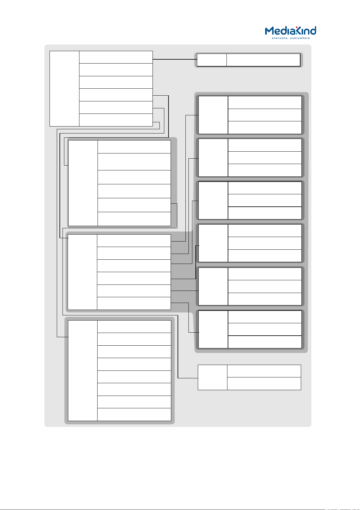
3–15
AUDIO
AUDIO 1
AUDIO 2
AUDIO 3
AUDIO 4
AUDIO 5
AUDIO 6
CH X+Y
Where X+Y =
1+2
3+4
5+6
7+8
9+10
11+12
13+14
15_16
NO EMBEDDING
---
NO EMBEDDING
---
NO EMBEDDING
---
NO EMBEDDING
---
NO EMBEDDING
---
NO EMBEDDING
---
NO EMBEDDING
---
NO EMBEDDING
---
VIDEO
COMPONENT SELECTION
NO SELECTION
USER PID: 0000
USER STD: MPEG-2
DELAY MODE: STANDARD
RX DELAY 4:2:0: 000
STATUS
SERVICE ID: 54206
SERVICE CLEAR
SERVICE
DECODE SERVICE
54206 – LUXE TV HD
VIDEO FAIL MODE
FREEZE FRAME
SERVICE HUNT
DISABLE
VIDEO
AUDIO
SDI EMBEDDING
AUDIO 2
COMPONENT SELECTION
NO SELECTION
USER PID: 0000
USER STD: MUS
DELAY ADJUSTMENT: 0.0 MS
AUDIO 3
COMPONENT SELECTION
NO SELECTION
USER PID: 0000
USER STD: MUS
DELAY ADJUSTMENT: 0.0 MS
AUDIO 4
COMPONENT SELECTION
NO SELECTION
USER PID: 0000
USER STD: MUS
DELAY ADJUSTMENT: 0.0 MS
AUDIO 5
COMPONENT SELECTION
NO SELECTION
USER PID: 0000
USER STD: MUS
DELAY ADJUSTMENT: 0.0 MS
AUDIO 6
COMPONENT SELECTION
NO SELECTION
USER PID: 0000
USER STD: MUS
DELAY ADJUSTMENT: 0.0 MS
AUDIO 1
COMPONENT SELECTION
NO SELECTION
USER PID: 0000
USER STD: MUS
DELAY ADJUSTMENT: 0.0 MS
TEST PATTERN:
NONE
FRAME SYNC: FALSE
STATUS: DISABLED
FSYNC
NTSC OFFSET: 000000
PAL OFFSET: 000000
RX8000 Integrated Receiver/Decoders
1553-FGB 101 759 Uen K
Figure 3-4 Sub-menu Service
www.mediakind.com
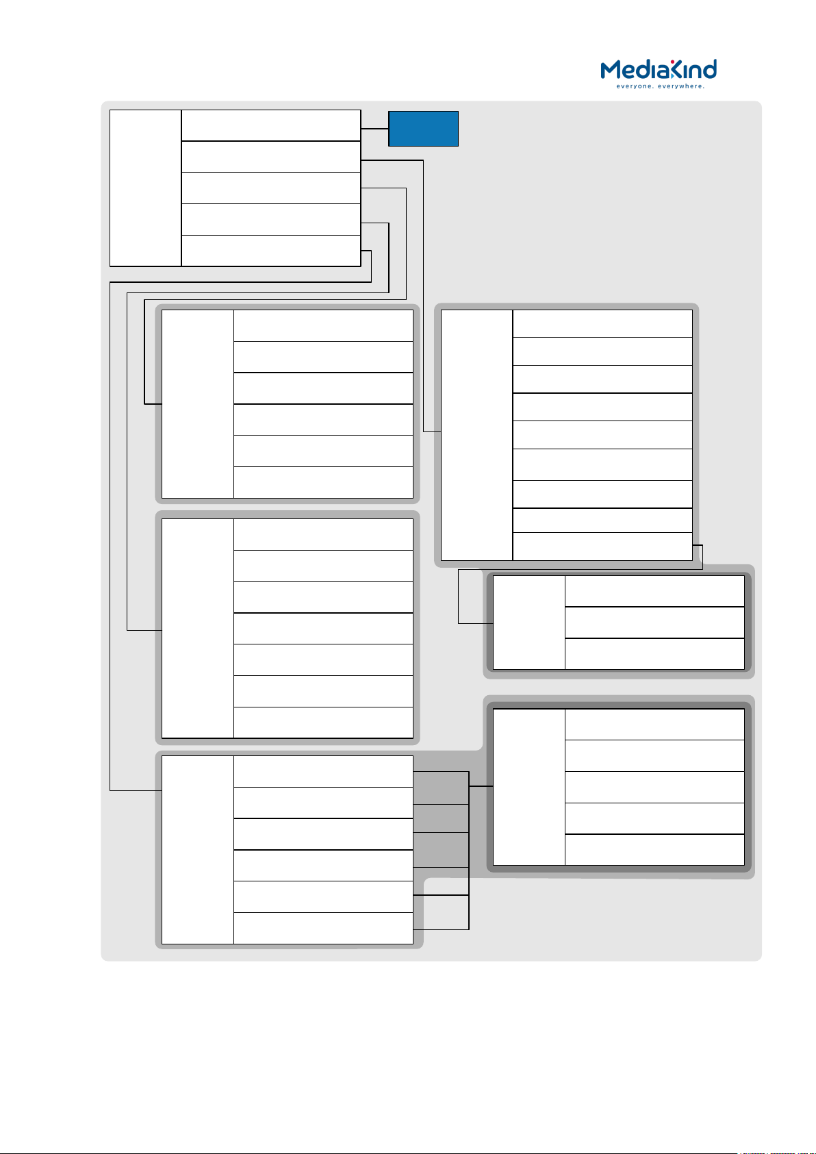
3–16
USER SUB
USER PID
0
USER COMPOSITION PAGE ID
0
USER ANCILLIARY PAGE ID
0
TELETEXT
TELETEXT PID
NO SELECTION
USER PID
0
STREAM STATUS
NOT PRESENT
OUTPUT STATUS
FAIL
TELETEXT INSERTION
ENABLE
TELETEXT PTS SYNCHRONISATION
ENABLE
VIDEO
STATUS
STOPPED
VIDEO STANDARD
UNKNOWN
ASPECT RATIO
UNKNOWN
FRAME RATE
0HZ
RESOLUTION
0X0
BIT RATE
0.000 MBITS/S
SCAN TYPE
INTERLACED
DECOD X
STATUS
STOPPED
BITRATE
--- KBITS/S
SAMPLING FREQUENCY
--- Hz
CODING STD
---
LANGUAGE 1
---
See page
VBI-VANC
DVB SUB
PID
NO SELECTION
STATE: OK
STATUS: NOT PRESENT
LANGUAGE
UNDEFINED
ENABLE SUBTITLES
FALSE
SCALE
NO SCALING
POSITION
CENTER BOTTOM
ERROR
NONE
USER DVB SUBTITLES
AUDIO
This may be 2
or 6
DECODER 1
DECODER 2
DECODER 3
DECODER 4
DECODER 5
DECODER 6
DECODE
VBI-VANC
DVB SUBS
TELETEXT
VIDEO STATUS PARAMETERS
AUDIO STATUS PARAMETERS
DVB SUBTITLE RECOVERY: OFF
Figure 3-5 Sub-menu Decode
RX8000 Integrated Receiver/Decoders
1553-FGB 101 759 Uen K
www.mediakind.com

3–17
VBI
-
VANC
VBI
VANC
CLOSED CAPTIONS
AMOL-
48 AND AMOL
-96
TVG
WSS
VITC
NTSC PEDESTAL
STATION ID
AFD
/
BAR
VBI
VBI PID
NO SELECTION
USER PID
0
VANC
STREAM STATUS
NOT PRESENT
OUTPUT STATUS
STOP
VANC
PID
0
ENABLE VANC
DISABLE
AMOL
AMOL STREAM STATUS
NOT PRESENT
AMOL OUTPUT STATUS
FAIL
AMOL INSERTION
ENABLE
TVG
TVG STREAM STATUS
NOT PRESENT
TVG OUTPUT STATUS
FAIL
TVG INSERTION
ENABLE
WSS
WSS STREAM STATUS
NOT PRESENT
WSS OUTPUT STATUS
FAIL
WSS INSERTION
ENABLE – VBI PID
NTSC
NTSC INSERTION
DISABLE
STATION
VANC STATION ID OUTPUT STATUS
STOP
ENABLE STATION ID
DISABLE
VANC STATION ID USER NAME
AFD/BAR
VANC AFD
BAR OUTPUT STATUS
STOP
ENABLE AFD BAR
DISABLE
CC
CC INSERTION
ENABLE
VBI
VANC
VBI
CC STREAM STATUS
PRESENT
CC OUTPUT STATUS
FAIL
RATING STREAM STATUS
NOT PRESENT
RATING OUTPUT STATUS
STOP
RATING VALUE
NONE
RATING INSERTION
DISABLE
VANC
VANC CC STREAM STATUS
PRESENT
VANC CC OUTPUT STATUS
INSERTED
VANC CC INSERTION LINE
11
VITC
VITC INSERTION
DISABLE
VBI
VANC
VBI
VITC OUTPUT STATUS
STOP
INSERTION LINE 525_1: 14
INSERTION LINE 525_
2:
16
INSERTION LINE
625_1
: 19
INSERTION LINE 625_
1:
21
VANC
VANC VITC OUTPUT STATUS
STOP
RX8000 Integrated Receiver/Decoders
1553-FGB 101 759 Uen K
Figure 3-6 Sub-menu VBI-VANC of Decode
www.mediakind.com
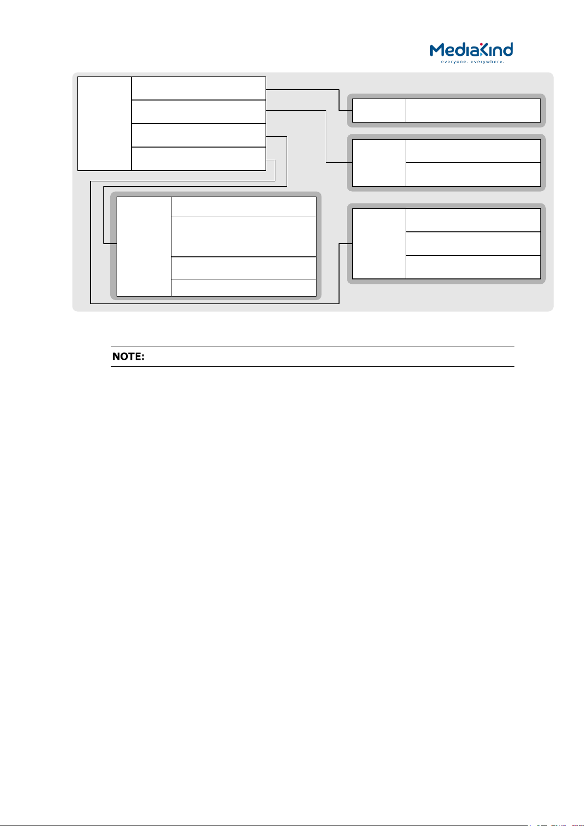
3–18
ALARMS
INPUT
OUTPUT
SERVICE
ENVIRONMENT
SERVICE
VIDEO NOT RUNNING
SET ALARM
DECODER
X
NOT RUNNING
1..
2
or 1
..6
SET ALARM
CLOSED CAPTION FAIL
SET ALARM
FILTER OUTPUT OVERFLOW
NO ALARM
OUTPUT
IPO ETHERNET IF 1 DOWN
NO ALARM
IPO ETHERNET IF 2 DOWN
NO ALARM
INPUT
NO TS LOCK
SET ALARM
ENV
OVERTEMPERATURE
SET ALARM
TEMP (MAX VALUE)
55
FAN X FAILED
SET ALARM
CA ERROR
SET ALARM
Figure 3-7 Sub-menu Alarms
The detail of each front panel element is explained throughout this chapter.
3.4. Using the Web Browser
The Web Browser interface is available as a standard feature on all models of the IRD. As of software
version 8.0.0, the IRD can be configured to present one of two web interface modes:
•
Dashboard View – A simplified view showing the most
common options on a single page that is compatible with most
modern web browsers. This feature available when the
RX8XXX/SWO/DASHBOARD license is enabled.
• Advanced View – The classic web interface that exposes all
the options across a number of tab views. This mode is
compatible with the browsers listed in section 3.4.1.
The Dashboard View will be presented by default but both modes have a button in the top right
corner of the web interface to allow the user to switch between them.
3.4.1. Setting Up Web Browser Remote Control
A personal computer (PC) running a Web Browser can be used to configure, control and monitor the
IRD remotely. The following web browsers have been tested:
•
Microsoft Internet Explorer (This is the only browser supported
by MediaKind)
• Mozilla Firefox (Functional but unsupported)
• Google Chrome (Functional but unsupported)
To set up Web Browser control:
RX8000 Integrated Receiver/Decoders
1553-FGB 101 759 Uen K
www.mediakind.com
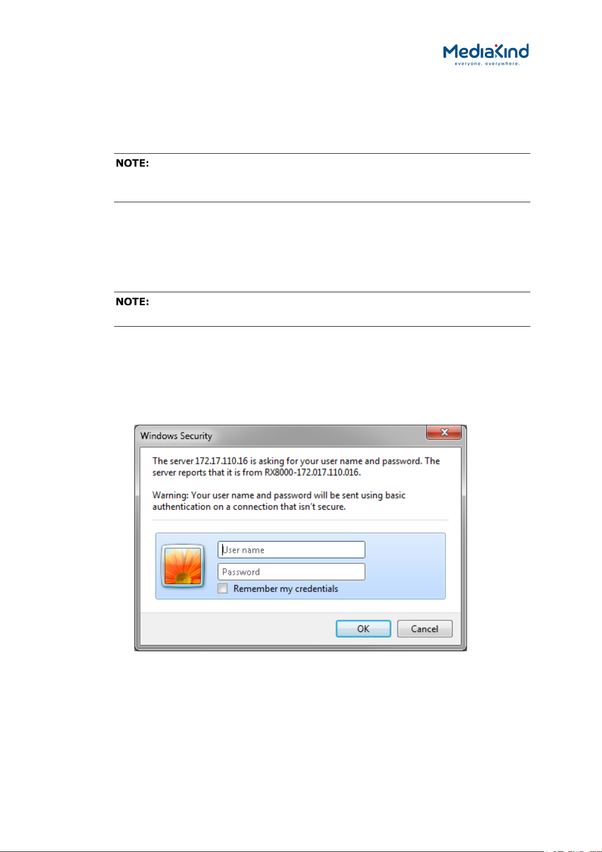
3–19
1. Connect the PC to either of the two IP control interfaces on the rear
of the IRD (labelled ETHERNET 1 / 2 or CONTROL 1 / 2).
2. Enter the settings for the relevant control port (IP Address, Subnet
and Gateway) via the front panel Network Settings menu.
If the IRD is connected to an existing network, or is not on the
same subnet as the control PC, assistance from the network administrator may
be required in modifying the network settings.
3. Open a Web Browser application on the PC.
4. Enter the IP address of the IRD into the address field of the Web
Browser. The Status page from the Advanced View or the single
page from the Dashboard View will appear in the Web Browser.
To assist with troubleshooting, the IP control ports will respond to ICMP
PING request messages.
3.4.2. XPO Password Protection
XPO Password Protection forces the user to enter a username and password in order access and
configure the IRD through the web browser interface. If this feature has been enabled
(RX8XXX/SWO/PW) then the user will be confronted with the following prompt.
Figure 3-8 Windows Security
The default settings from the factory are:
User Name: username
Password: password
RX8000 Integrated Receiver/Decoders
1553-FGB 101 759 Uen K
www.mediakind.com

3–20
When access has been granted for the first time, it is recommended that the XPO password is
changed immediately. This can be changed by navigating to the Device Info > XPO Password
Protection option from the Advanced View:
Figure 3-9 XPO Password Protection Settings
Enable/Disable Password Protection
Enable Password Protection – This control overrides the
•
password protection control. When enabled, the user must
enter their password credentials every time a new web
interface session is connected to the IRD device before being
able to modify its configuration. When disabled (the default),
anyone can gain access to the web interface and modify its
configuration.
Change Password
User Name – Used to enter the new desired user name.
•
• Old Password – Used to enter the current password.
• New Password – Used to enter the new desired password.
• Confirm New Password – Used to confirm the new desired
password.
In order to change the XPO password, all four of these fields must be populated before clicking on
Apply Changes.
If the username or password has been forgotten then please
contact MediaKind Customer Services for steps to reset the password.
RX8000 Integrated Receiver/Decoders
1553-FGB 101 759 Uen K
www.mediakind.com

3–21
RX8200
RX8310
RX8315
RX8320
RX8330
Web Front Panel SNMP Serial
Remote
3.4.3. Using the Web Browser Interface in Dashboard View
3.4.3.1. Availability
= Option B = Supplied with Base Model
B B B B B
3.4.3.2. Order Items
Option Name Board Type FAZ Number Marketing Code
There are no order items with this functionality
3.4.3.3. Control
3.4.3.4. License Keys
Marketing Code Description FAZ Number License Key Name
RX8200/SWO/DASHBOARD Simplified
Dashboard overlay
TBD RX8XXX/SWO/DASHBOARD
3.4.3.5. Dashboard View
When in Dashboard View, the Web Browser Interface displays a simplified view with the most
commonly used options accessible from a single page. The Dashboard View mode dynamically
updates status information and current configuration options without the need to refresh the web
browser.
RX8000 Integrated Receiver/Decoders
1553-FGB 101 759 Uen K
www.mediakind.com

3–22
Header
Overall Status
Unit Model Number and Name
Advanced View button
Alarms button
C/N Margin
Meter
Configuration Panes
Toolbar
Pane
Graphical
RX8000 Integrated Receiver/Decoders
1553-FGB 101 759 Uen K
Figure 3-10 Example of the Dashboard View
• Header – The header of the web page displays the MediaKind
logo and the unit model number/name.
• Alarms Button – This will open a window listing the currently
active alarms reported by the unit.
• Toolbar – The simplified toolbar provides two buttons
applicable to the Dashboard View: The Apply button will push
any configuration changes to the unit. The Discard button will
discard configuration changes that have not yet been applied.
• Advanced View Button – When in the Dashboard View mode,
this button will switch the web interface to the Advanced View.
• Overall Status Pane – Contains a subset of sections to the
left of the page that summarize the operating status of the
www.mediakind.com

3–23
unit. These status values are updated dynamically by the
Dashboard View.
• Configuration Panes – A simplified view of the most popular
configuration settings to the right of the page that can be
applied to the unit.
• C/N Margin Graphical Meter – If fitted with a satellite input
card, the current C/N Margin for the locked satellite signal is
reported and visually represented by a graphical meter.
The Dashboard View mode is available on most IRD variants and is enabled using the
RX8200/SWO/DASHBOARD software option.
The following table lists the icons, buttons and other symbols used in this web interface mode.
Table 3-1 Web Page Icons, Buttons and Symbols in the Dashboard View
Item Description
Navigation
Click on this button to view the currently active alarms raised by
the unit.
Parameter Presentation
Click on this button to push configuration changes to unit that will
be applied immediately.
Click on this button to discard all configuration changes that have
not yet been applied. Changes will revert to the active settings.
Switch from the Dashboard View mode to the Advanced View
mode.
The icon to the right of each pane is used to collapse or expand
an individual pane and its contents:
Pane is expanded, click to collapse.
Pane is collapsed, click to expand.
3.4.3.6. Simplified Settings
The status and configuration settings exposed in the panes reflect the values and a subset of the
options available in the Advanced View.
3.4.3.6.1. Status Pane
Displays live status information reported by the unit. It is broken down in to subset sections that are
dependent on licenses and options fitted: overall Input Status; C/N Margin graphical meter; Service
Status; Video Status; Audio Status; CC/Subtitle Status and CA Status.
3.4.3.6.2. C/N Margin (dB) Pane
The C/N Margin Pane is only shown if a Satellite Card is fitted to the unit. When the Satellite Card is
locked to a satellite signal, the C/N Margin is reported in both numeric and graphical form. The red
and green bar represents the C/N Margin value on the graphical meter.
RX8000 Integrated Receiver/Decoders
1553-FGB 101 759 Uen K
www.mediakind.com

3–24
Figure 3-11 C/N Margin Status Pane
The C/N Margin (Min Value) is the threshold for the C/N Margin alarm that is configured in the
Advanced View. The red part of the meter represents values below this threshold. The green part of
the meter represents values above this threshold. The C/N Margin alarm remains cleared unless the
measured C/N Margin value drops below this threshold at which point the C/N Margin alarm will be
raised.
3.4.3.6.3. Input Pane
This exposes commonly used input configuration settings for the unit. Only ASI, IP and satellite
settings are exposed here. For other input types such as DVB-T2 or G.703, it will be necessary to
switch over to the Advanced View.
3.4.3.6.4. CA Pane
This exposes commonly used Conditional Access configuration settings for the unit. Only settings for
BISS CA are exposed here. For other CA types such as Director or DVB-CI, it will be necessary to
switch over to the Advanced View.
3.4.3.6.5. Decode Pane
Decode settings such as service selection and audio component selection are exposed here. For
other advanced settings, it will be necessary to switch over to the Advanced View.
3.4.3.6.6. Output Pane
The Output Pane provides access to common output configuration settings such as TS Feed and ASI
or SDI control settings. For advanced settings such TS filtering settings, it will be necessary to switch
over to the Advanced View.
3.4.3.6.7. Alarms Button
To view any currently active alarms from the Dashboard View, click on the Alarms button from the
top of the web page. A pop-up window will appear similar to that shown below.
RX8000 Integrated Receiver/Decoders
1553-FGB 101 759 Uen K
www.mediakind.com

3–25
RX8200
RX8310
RX8315
RX8320
RX8330
Web Front Panel SNMP Serial
Remote
Figure 3-12 Example of Active Alarms from the Dashboard View
3.4.4. Using the Web Browser Interface in Advanced View
3.4.4.1. Availability
= Option B = Supplied with Base Model
B B B B B
3.4.4.2. Order Items
Option Name Board Type FAZ Number Marketing Code
There are no order items with this functionality
3.4.4.3. Control
3.4.4.4. License Keys
Marketing Code Description FAZ Number License Key Name
There are no license keys required for this feature
RX8000 Integrated Receiver/Decoders
1553-FGB 101 759 Uen K
www.mediakind.com

3–26
Header
Function Tabs
Main Web Page
Unit Model Number and Name
About
Navigation Path
Toolbar
Dashboard
Result Frame
3.4.4.5. Advanced View
When in Advanced View, the Web Browser Interface displays various web pages, corresponding to
the different functions of the IRD, as shown in Figure 3-13.
button
button
RX8000 Integrated Receiver/Decoders
1553-FGB 101 759 Uen K
Figure 3-13 Web Page Overview in Advanced View
• Header – The header of the web page displays the MediaKind
logo and the unit model number/name.
• Dashboard Button – When in Advanced View mode, this
button will switch the web interface to the Dashboard View.
• About – When clicked, displays an information dialog about
the unit, including the software version number. Click the OK
button to close the dialog.
www.mediakind.com
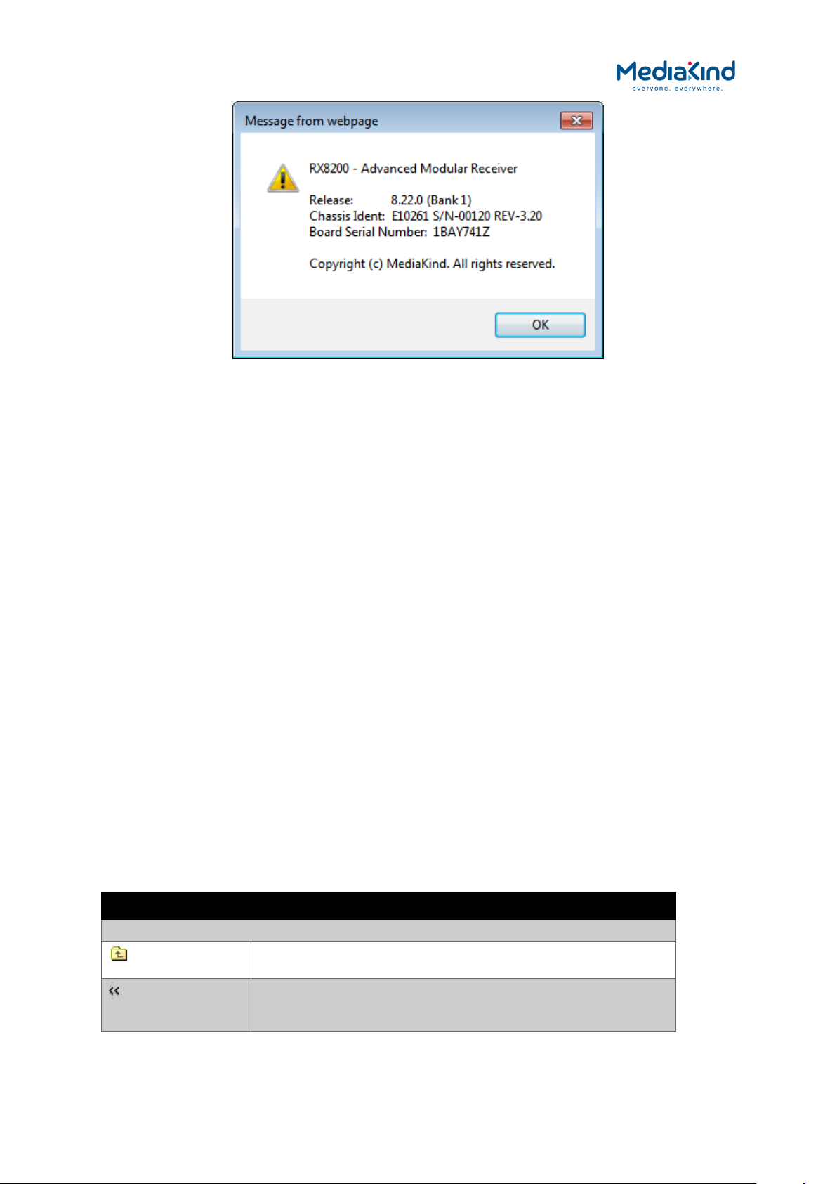
3–27
Figure 3-14 About Dialog
• Function Tabs – The web pages for control and monitoring of
specific functions are accessed by selecting the appropriate
function tab along the top of the web page. When you switch
between tabs, the browser remembers the path within each
tab.
• Navigation Path – The web pages are organized into a tree-
like structure, like the directory on a computer. The current
navigation path is always displayed at the top of the web page
showing the route taken to the current page. To return to a
higher level (parent) web page (folder), simply click on the
relevant name link in the Navigation Path or click the Top Level
Folder icon in the toolbar.
• Toolbar – The toolbar provides various tools/buttons
depending on the web page selected.
• Main Web Page – The main content of the web page displays
parameters and their current values. Some parameters can be
modified by overtyping, selecting an option from a drop-down
menu or by placing a tick in a checkbox as required. Any
changes made will not be applied to the unit until the Apply
Changes button is clicked in the Toolbar.
• Result Frame – The Result Frame at the bottom of the screen
will feedback results of any command actions. SUCCESS,
SUCCESS with warnings or ERROR may be displayed, with
further details as appropriate for more complex actions.
The following table lists the various icons, buttons and other symbols used in these web pages.
Table 3-2 Web Page Icons, Buttons and Symbols
Item Description
Navigation
RX8000 Integrated Receiver/Decoders
1553-FGB 101 759 Uen K
www.mediakind.com
Click on this icon to navigate one step up (to the parent folder)
in the folder structure.
Click on this icon to navigate back to the previous view. This
icon typically appears when you are editing a single record in a
table or a sub-table.

3–28
Item Description
Click on this button to apply the changes you have made to
parameters in this web page. The result of your actions will be
shown in the Result Frame.
Parameter Presentation
Click on this button to refresh the current screen. This may be
useful if the screen contains read-only status parameters such
as measured bit rates.
The folder icon is used to represent a web page in the system.
A folder is similar to a directory in a file system. The button
shown left indicates that a further sub-folder or lower-level web
page is available by clicking on the button.
This icon is used to represent a table. A table normally consists
of multiple items, where each item consists of several fields.
Click on this button to reboot the unit.
Table Operations
Add Item
Delete Selected
Delete All Press this button to delete all items in a table. Note that this
Click on this button to view the overall release version running
on the unit.
Switch from the Advanced View mode to the Dashboard View
mode.
These buttons are used to navigate a table of data when it is
too large to fit into one screen. The symbols are:
go to start
previous screen
next screen
go to end
Press this button to add a new item into the table. You will be
taken to the "New item" screen in the table.
Pres this button to delete selected items. You select items by
clicking the checkboxes in front of each row.
will delete the entire table, not only the items you may see on
the screen at any time.
3.5. SNMP
Simple Network Management Protocol (SNMP) is a network protocol used to monitor
network-attached devices for conditions that warrant administrative attention. SNMP consists of a
set of standards for network management, including an application layer protocol, a database
schema, and a set of data objects.
The IRD supports SNMP Versions 2C and 3 as a standard feature.
3.5.1. Setting Up SNMP Remote Control
SNMP remote control is enabled by default.
To set up SNMP remote control:
1. Ensure the Web Browser Interface is connected and working and
switch over to the Advanced View mode.
RX8000 Integrated Receiver/Decoders
1553-FGB 101 759 Uen K
www.mediakind.com

3–29
2. From the browser SNMP tab, select the version of SNMP required
(V2C or V3).
3. Ensure the trap community, read-write community, and read-only
community are configured as public or private in the same way as
the MIB browse or SNMP application being used.
3.5.1.1. SNMP > Parameters
Figure 3-15 SNMP Web Page
• MIB Format – Selects between RX8000 (Default) and RX1290
mode. Setting to RX1290 mode causes the unit to respond to
a subset of the RX1290’s MIBs rather than the standard full
RX8000 MIBs. For further information and advice regarding
this setting contact MediaKind Customer Services
The IRD must be reset for these changes to take effect.
• Version – Enables selection of the SNMP version from a drop-
down menu.
• Sys Services – Enables input of a value for MIB-2 services
that this device primarily offers (MIB-II RFC1213). See MIB-2
for definition.
• System Name – Enables input of a MIB-2 sys name, which
should be an administratively-assigned name.
• Trap Community – Enables input of type of trap community.
• Read Write Community – Enables input of type of read write
community.
• Read Only Community – Enables input of type of read only
community.
RX8000 Integrated Receiver/Decoders
1553-FGB 101 759 Uen K
www.mediakind.com

3–30
• Location – Enables input of a MIB sys location which is the
physical location of this node.
• Description – Enables input of a MIB sys description which
should be a textual description of the entity.
• Contact – Enables input of a MIB sys contact which should be
a textual identification of the person to be contacted.
• Boot Count – Displays the number of times the unit has been
restarted.
3.5.2. Downloading the MIB
SNMP exposes management data in the form of variables on the managed systems, which describe
the system configuration. The SNMP Management Information Base (MIB) stored on each unit
defines which information (variables) should be monitored. The MIB may be downloaded from the
unit as a zip file using the Web Browser interface. These variables can then be queried (and set) by
managing applications.
Please refer to the managing application documentation for compiling third-party MIBs.
The ZIP file is no longer password protected. If an older version of the ZIP
file is downloaded, this may be protected with the password “Stoneham”.
3.6. Director
MediaKind’s Director Over-Air Control (OAC) system is available either as a standard feature or as an
option on all of the RX8000 range IRDs, except for the RX8320 and RX8330C. OAC is a subset of the
Director facility and is a remote control protocol which is used to access the units using MediaKind’s
nCompass Control System. An Over-Air Software Download facility is also provided which allows the
IRD software to be upgraded without a network connection.
For more detailed information on MediaKind Director remote control, contact MediaKind.
3.6.1. Setting up Director Remote Control
For the unit to be controlled via OAC, the control mode of the IRD needs to be set to Director OAC
control mode. This can be achieved either via:
•
The front panel, using menu 5.2 DIRECTOR and sub-menus.
• The web interface using the CA tab page from the Advanced
View mode.
3.6.2. Over-Air Control (OAC) Lockout
When the unit is in OAC control mode, it is possible for the remote control operator to issue a local
lockout command to the IRD. This will effectively deny the local user access to configuring the unit.
However, if a situation occurs whereby the local user needs to regain control over the unit without a
local lockout relinquish command being sent from the OAC control PC, a four-digit Personal
Identification Number (PIN) may be entered through the front panel.
RX8000 Integrated Receiver/Decoders
1553-FGB 101 759 Uen K
www.mediakind.com

3–31
CAUTION: If the PIN is unknown it is possible to recover the PIN from the front
panel. For more details on reseting the local lock out PIN, contact
MediaKind.
The user creates the PIN at lockout time. To obtain the PIN, please consult the person responsible
for the administration of the unit.
3.7. RS232/485 RCP
RS232/485 Remote Control Protocol (RCP) is only available as an option card on the RX8200 IRD.
This enables control of the unit through the RS232/485 serial connector on the rear panel of the
unit, using MediaKind’s proprietary remote control protocol. This feature allows customers, who
may be upgrading their current systems to the RX8000 series, to continue using their current scripts
for IRD control.
For more detailed information about RS232/485 RCP remote control protocols, contact MediaKind.
3.8. Local Control Lockout
Common for all control methods is that the equipment can still be controlled locally from the front
panel interface unless the front panel is disabled. This can be achieved either:
•
Locally using the front panel menu 1.8.1 FRONT PANEL
LOCKOUT to prevent local control from being re-established.
• Remotely using the appropriate remote command, depending
on the remote control method being used.
When front panel lockout is set to ON / ENABLE, the user can still browse and navigate the front
panel menus. However, none of the menu items can be edited (except for Menu 1.8.1 to
enable/disable front panel lockout). The LCD will continue to display summary information screens.
3.9. General Web Browser Pages
The web interface served by the IRD will be one of two modes: the Dashboard View or the
Advanced View.
All references to accessing the web interface throughout this manual are via the Advanced View only
unless specified.
3.9.1. Status
Provided that the network is correctly configured, the following status page should be automatically
loaded and displayed.
RX8000 Integrated Receiver/Decoders
1553-FGB 101 759 Uen K
www.mediakind.com

3–32
Figure 3-16 Status Web Page
This page provides a number of top-level status items:
Name – Shows the configured device name for this IRD.
•
• IP Address #1 – The configured IP address of the IRD’s
Ethernet control port 1
• IP Address #2 – The configured IP address of the IRD’s
Ethernet control port 2
• Current Status – The current top level alarm status for the
IRD. This reflects the highest level alarm active in the unit.
• Current Time – The current time reported is taken from the
following (in priority order):
- TDT (DVB) or STT (ATSC) extracted from the input
Transport Stream
- NTP server
- Internal time with epoch of “2000-01-01 00:00:00”
• Uptime – The elapsed time since power-up.
• Input Status – The input TS lock status of the unit.
RX8000 Integrated Receiver/Decoders
1553-FGB 101 759 Uen K
www.mediakind.com
• Video Status – The decode status of the currently selected
video decoder.
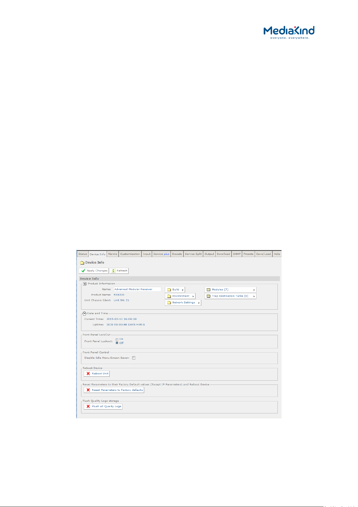
3–33
• Audio Status – The decode status of the currently selected
audio decoders.
• CA Status – The status of the descrambler block within the
IRD.
• Service Filter Status (shown if licensed) – Indicates the state
of the service filter block.
• Output Feed – The status of the output Transport Stream
feed.
• Mode – Indicates whether unit configuration is active or
redundant.
A small window located at the bottom left of the Status Page will show events raised and all the
necessary details of those events.
The About button, located on the top right-hand side of the Status page shows, when selected,
details of the IRD such as software version and serial number.
The Clear button, located next to the Refresh button on the top left-hand side of the Status page, is
used to clear the Base Decoder Failure alarm. For more information on this alarm, refer to section
3.9.3.9, Base Decoder Failure Alarm.
3.9.2. Device Info
The Device Info page provides access to system level settings of the IRD. To view this web page,
select the Device Info tab from the top of the current web page.
Product Information
RX8000 Integrated Receiver/Decoders
1553-FGB 101 759 Uen K
www.mediakind.com
Figure 3-17 Device Info Web Page

3–34
Date and Time
Front Panel LockOut
• Name – This field allows a descriptive name to be assigned to
the IRD. The default name is the IRD model name.
• Product Name – The model of the product.
• Unit Chassis Ident – This is a unique identity value that
matches the label printed on the side of the device chassis.
• Build/Environment/Network Settings/Modules/Trap Destination
Table – These buttons access sub-menu pages, described
below.
Current Time – The current time reported is taken from the
•
following (in priority order):
- TDT (DVB) or STT (ATSC) extracted from the input
Transport Stream
- NTP server
- Internal time with epoch of “2000-01-01 00:00:00”
• Uptime – The elapsed time since power-up.
Front Panel Lockout On/Off – Indicates whether the front
•
panel controls are active or inactive.
Front Panel Control
•
Disable Idle Menu Screen Saver – Disables the front panel
screen saver. The screen saver is activated if there is no
navigation activity for more than 5 minutes.
• Flash the front panel LED(20 mins duration) – If set On,
the front panel LED will flash on and off for approximately 20
minutes before resuming normal operation. This can be used to
locate a particular unit if many IRDs are co-located.
Reboot Device
Reboot Unit – Selecting this button will perform a hardware
•
reset of the IRD.
Reset Parameters to their Factory Default values
Reset Parameters to Factory Defaults – Selecting this
•
button will set all parameters to their factory default values
(except for the network IP parameters e.g. IP address and
subnet mask) and perform a hardware reset of the IRD.
Flush Quality Logs storage
Flush all Quality Logs – Selecting this button will flush all the
•
quality logs.
A number of further web pages are accessible from the Device Info page and these are described in
the following paragraphs.
3.9.2.1. Device Info > Build
This page gives details of the build and version information for the equipment. There are no fields on
this page that may be edited by the user.
RX8000 Integrated Receiver/Decoders
1553-FGB 101 759 Uen K
www.mediakind.com

3–35
To view this page, select the Build button from the Device Info Page.
Figure 3-18 Device Info > Build Web Page
Build
SW Version – Displays the software version and the currently
•
selected software bank.
• HW ID – Displays the revision number of the base unit
hardware.
• TS FPGA Version – Displays the version number and build
date for the Transport Stream routing FPGA.
• SD FPGA Version – Displays the version number and build
date for the SD video control and routing FPGA.
• HD FPGA Version – Displays version number and build date
for the HD video (720P and above) control and routing FPGA.
• Audio DSP Version – Displays the version of the audio
decoder DSP.
• PS Version – Displays the power sequence micro-controller
version.
3.9.2.2. Device Info > Environment
This page gives details of the physical environment of the equipment i.e. temperature and fan
speeds.
There are no fields on this page which may be edited by the user. Selecting the Refresh button will
update the status values.
To view this page, select the Environment button from the Device Info Page.
RX8000 Integrated Receiver/Decoders
1553-FGB 101 759 Uen K
www.mediakind.com

3–36
Environment
Figure 3-19 Device Info > Environment Web Page
Temperature – Displays the temperature measured inside the
•
unit (°Celsius/°Fahrenheit).
• Fan 1/2/3/4 Speed – Displays the speed (revolutions per
minute) of the fans fitted inside the unit.
3.9.2.3. Device Info > Network Settings
This page gives details of settings for the Ethernet Control ports. Fields on this page allow the user to
configure Ethernet Control ports 1 and 2.
Any changes made to any of the settings will not be applied until the Apply Changes button is
selected. Selecting the Refresh button will update current settings and status values.
To view this page, select the Network Settings button from the Device Info Page.
Figure 3-20 Device Info > Network Settings Web Page
3.9.2.3.1. Control 1/2
RX8000 Integrated Receiver/Decoders
1553-FGB 101 759 Uen K
www.mediakind.com
• IP – The IP address of this control port.
• Subnet – The Subnet address of this control port.

3–37
• Link Config – The link speed of the control port. This can be:
• 10 BaseT
• 10 BaseT Half Duplex
• 100 BaseT
• 100 BaseT Half Duplex
• Auto
• MAC Address – Displays the MAC address assigned to this
control port (non-editable).
• Link Status – Displays the operating speed and mode of the
established Control link (e.g. 100 Mb Full Duplex).
If the IP address of Control 1 and Control 2 are set to the same value, the
MAC Address of Control 2 will be automatically adjusted to match that of Control
1.
3.9.2.3.2. Common
• Gateway – The Gateway address common for both networks
(Control 1 and 2).
3.9.2.3.3. Network Time Update
The implemented Simple Network Time Protocol (SNTP) client is able to synchronize the system time
with second tier NTP servers.
Configuration is only possible via the web browser interface on the page Device Info > Network
Settings.
•
Network Time Update – ON/OFF.
• Time Zone – GMT + 12.
• Daylight Saving – ON/OFF.
• NTP Server No 1 – IP Address.
• NTP Server No 2 – IP Address.
• NTP Server No 3 – IP Address.
• NTP Server No 4 – IP Address.
If the SNTP interface is not being used, its associated alarm should be
masked.
If the input stream contains TDT, this will override the NTP server derived time.
3.9.2.3.4. DSM Parameters
Device Status Message (DSM) packets and Control Status Message (CSM) packets are an MediaKind
proprietary protocol used within an nCC network to control redundancy. These packets are IP
datagrams on specific IP addresses; they are used to provide the current health of the unit / network
RX8000 Integrated Receiver/Decoders
1553-FGB 101 759 Uen K
www.mediakind.com

3–38
and to indicate whether the unit is ‘spare’ or ‘live’. For more information about system redundancy
within nCC please contact your system administrator.
The controls for this are:
DSM IP – The IP address of the DSM IP packets to be placed
•
on the network.
• DSM Dest Port – The destination port for the DSM packets.
• DSM TTL – User configuration for the time to live filed in the
DSM packets.
• DSM TOS – User configuration of the type of service
(differentiated services field) within the packet.
• DSM TX Interval – Interval in ms between each DSM packet
placed onto the network.
• CSM IP – The IP address of the CSM packets within the
network.
• CSM Dest Port – The destination port for the CSM packets.
• CSM Timeout – Timeout in ms before CSMs are considered to
be absent from the network.
• Connection Status – Status of the unit within the redundancy
network.
• DSM Version – There are several versions of CSM / DSM
redundancy within nCC networks, for the correct version of
redundancy for your system please contact your system
administrator.
3.9.2.3.5. MAC Address Configuration
This permits the overriding of the MAC addresses used by the Control Ethernet ports and the IP
Input Data Ethernet ports of the IP Input card (1914) and Combined Satellite/IP Input card (1931).
The first 3 octets of the MAC address are the MediaKind OUI, followed by 1 octet identifying the
MediaKind product, and a final pair of octets derived from the serial number of the Base unit.
It is recommended that these settings not be adjusted unless advised
to do so by MediaKind Customer Services.
• EUROCARD MAC Serial - This allows the lower 2 octets of the
IP Input card (1914) and Combined Satellite/IP Input card
(1931), if fitted, to be changed to a manually specified value.
• Default EUROCARD MAC Serial - This is the default value
that will be used for the EUROCARD MAC Serial.
RX8000 Integrated Receiver/Decoders
1553-FGB 101 759 Uen K
www.mediakind.com
• Incorrect MAC Address – This option is only exposed on
some RX8300 variant IRDs where there was an issue with the
assignment of MAC address to the Control Ethernet ports.
Changing this setting will result in the Control MAC
address being changed, potentially causing a loss of
connectivity to the receiver.
• Clearing this tick box will mean the correct MAC address is calculated
and applied to the Control Ethernet ports.

3–39
RX8200
RX8310
RX8315
RX8320
RX8330
• Setting this tick box will mean the legacy MAC address is calculated
and applied to the Control Ethernet ports.
3.9.2.4. Device Info > Remote Control
3.9.2.4.1. Availability
= Option B = Supplied with Base Model
3.9.2.4.2. Order Items
Option Name Board Type FAZ Number Marketing Code
RS232 Remote Data Card 1927 FAZ 101 0113/17 RX8200/HWO/RS232
3.9.2.4.3. Functional Description
The RS232 Remote Data option card provides the following features:
RS232 / RS485 Serial Remote Control
•
• Alarm Relay (the behavior is identical to the Alarm Relay
interface on units that do not have the RS232 Remote Data
card fitted)
• Low Speed Data (see section 0)
This option card enables the IRD to be controlled from a PC or similar device through a standard
serial port that supports the MediaKind Serial Remote Control Protocol for RX8000 IRD.
The MediaKind protocol is based on the original System 3000/Alteia protocol and often referred to
as the Alteia Remote Control protocol.
For command details on the MediaKind Serial Remote Protocol supported by the IRD, refer to the
RX8000 Remote Control Protocol document. Please contact Customer Support for more information.
RX8000 Integrated Receiver/Decoders
1553-FGB 101 759 Uen K
www.mediakind.com

3–40
3.9.2.4.4. Configuration
Figure 3-21 Device Info > Remote Control
• Serial Remote Address – This defines the Serial Remote
Address assigned to the unit. When connected to a network
that controls multiple IRDs, each address should be unique.
• Serial Remote Interface – Configures serial interface
standard to apply to the Remote Control port:
• RS-232 –This configures the Remote Control port to use RS-
232 mode.
• RS-485 – This configures the Remote Control port to use RS-
485 mode and makes it possible to control multiple IRD from a
single controller where the devices are connected to a common
cable-rail.
• Serial Remote Interface Duplexity – Configures the duplex
mode to apply to the Remote Control port:
• Half-Duplex
• Full-Duplex
• Serial Remote Protocol Version – This selects which of the
serial remote protocol versions to use:
• RX8000 –This is the default serial remote control protocol to
use which controls most of the functionality available to the
IRD.
• RX1290 – This configures the IRD to follow the RX1290 serial
remote control protocol where possible. Some of the RX1290
functionality may not be available on the IRD and the RX1290
protocol cannot access all of the features supported by the
RX8000, so controlling the IRD using this protocol version will
be limited.
3.9.2.5. Device Info > Modules
This page gives a list of all modules contained in the equipment chassis.
RX8000 Integrated Receiver/Decoders
1553-FGB 101 759 Uen K
www.mediakind.com

3–41
There are no fields on this page which may be edited by the user. Selecting the Refresh button will
update current settings and status values.
To view this page, select the Modules button from the Device Info Page.
Figure 3-22 Device Info > Modules Web Page
The following modules are supported by the unit:
Table 3-3 Supported Modules
Board Type Description
1900 RX8200 Motherboard
1901 RX8310/20 Motherboard
1902 RX8315/30 Motherboard
1910 Control Interface (RX8200 only)
1911 DVB S2 Input
1912 DVB S2 2nd Generation Input (RX8310B only)
1913 8VSB Terrestrial Input
1914 IP Input
1915 HD Video Output (RX8200 only)
1916 Analogue Audio Output
1918 IP Output (RX8200 only)
1919 IP Output (RX83xx only)
1920 MPEG 2 4:2:2 Decoder, 1st generation (RX8200 only)
1921 MPEG 2/4 AVC 4:2:2 Decoder, 2nd generation (RX8200 only)
1922 Common Interface Descrambler (RX8200 only)
1923 NDS Descrambler (RX8200 only)
1924 G.703 Input
1925 8VSB Terrestrial Input (RX8320 only)
1926 Russian SECAM Video Output (RX8330 only)
1927 Remote Data Card (RX8200 only)
1928 DVB S2 2nd Generation Input
1929 G.703 Input (RX8200 only)
1930 High Quality Down-converter (RX8200 only)
1931 DVB S2/IP Input (RX8200 only)
1932 DVB-T2 Input (RX8200 only)
1933 Multi Format 4:2:2 Decoder, 3rd generation (RX8200 only)
1934 Small Form Factor (SFF) Bi-directional IP Card
1935 DVB-S2X Input (RX8200 only)
RX8000 Integrated Receiver/Decoders
1553-FGB 101 759 Uen K
www.mediakind.com
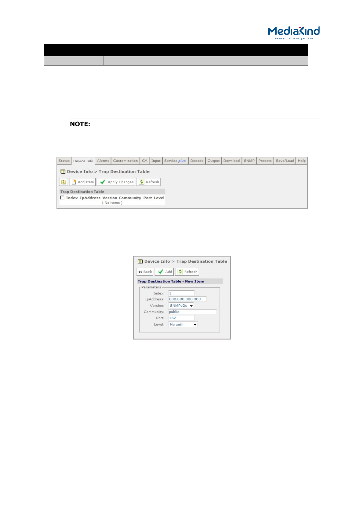
3–42
Board Type Description
1936 Enhanced Multi Format 4:2:2 Decoder, 4th generation (RX8200 only)
3.9.2.6. Device Info > Trap Destination Table
When an alarm occurs within the equipment, an SNMP Trap message is sent to all destinations and a
list of these destinations is given in this web page.
The SNMP alarm trap sent will contain sysUpTime. This is the elapsed time
since the SNMP agent was reinitialized and this is not configurable on the IRD
To view this page, select the Trap Destination button from the Device Info page.
Figure 3-23 Device Info > Trap Destination Table Web Page
To add a new item to this page:
1. Select the Add Item button. The following page is displayed:
Figure 3-24 Trap Destination Table > Add Item Web Page
2. Enter the required values in the appropriate fields or select values
from the drop-down menus.
3. Select the Add button to add the item to the Trap Destination table.
4. Select the Back button to return to the Device Info > Trap
Destination Table web page. This will abort any unsaved changes.
5. Select the Apply Changes button to confirm changes.
Selecting the Refresh button will ensure that the latest information is being displayed from the
current values of the equipment.
RX8000 Integrated Receiver/Decoders
1553-FGB 101 759 Uen K
www.mediakind.com

3–43
3.9.3. Alarms
The Alarms page provides access to the alarm settings for the IRD.
The content of this page is composed mainly of fields with drop-down menus which allow the setting
or masking of various alarms and check boxes which can be used to activate relay mapping. Two of
the alarm fields, namely C/N Margin and Over Temperature also have associated entry fields which
allow the user to enter a threshold value which, if exceeded, will activate the alarm.
Setting an alarm property to Set Alarm will cause the following if an alarm event is raised:
•
Activation of the front panel Alarm LED
• Raise of an alarm event in the main Status page and record it
in the Alarm Log.
• If configured for relay mapping, the Summary Alarm Relay
will be triggered.
Setting an alarm property to No Alarm masks an alarm event and therefore any of the behaviors
described above. An alarm property can be mapped to the Summary Alarm Relay if the associated
Relay Mapping check box is checked.
Any changes which are made to the alarm settings shown may be confirmed by selecting the Apply
Changes button. Selecting the Refresh button will ensure that the latest information is being
displayed from the current values of the equipment.
To view this page, select the Alarms tab from the top of the current web page.
Figure 3-25 Configuring Alarm Behavior
3.9.3.1. Identifier Control
• Alarm Mode – Configures how the unique identifiers are
assigned to each alarm type.
RX8000 Integrated Receiver/Decoders
1553-FGB 101 759 Uen K
www.mediakind.com
• Dynamic: The unique identifier value assigned to each alarm
type is dynamically assigned during start-up based on the
sequence when it is registered to the Alarm Manager. These
identifiers can change depending on what hardware and
software options are present.
• Compatibility: The unique identifier value assigned to each
alarm type is fixed to the values listed in Appendix C.
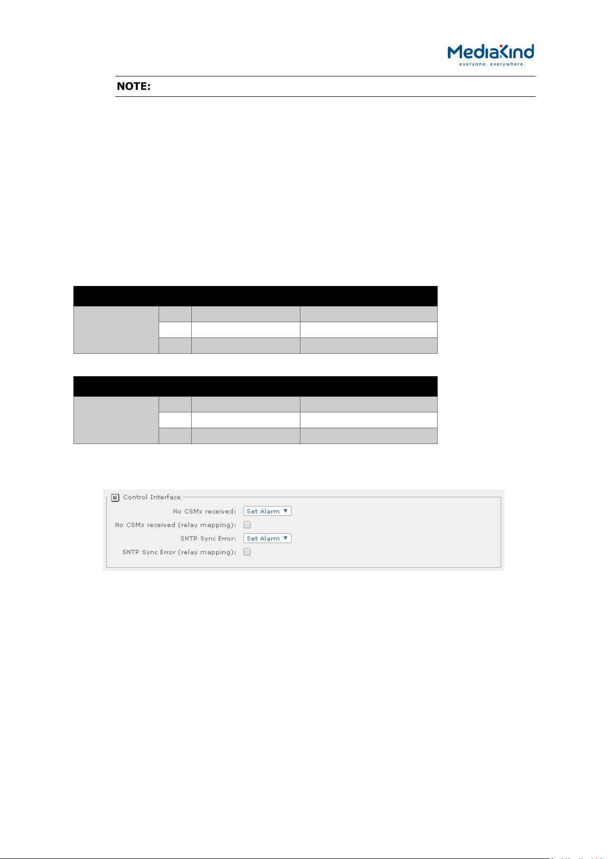
3–44
The IRD must be reset for these changes to take effect.
3.9.3.2. Relay Configuration
• Relay Mode – Change the behavior of the Summary Alarm
Relay so that it is compatible across different IRD software
releases.
• Legacy: This configures the behavior of the Summary Alarm
Relay to match that of software versions before 5.12.0. Refer
to Table 3-4 for pin assignments.
• Revised: This configures the behavior of the Summary Alarm
Relay to match that of software version 5.12.0 onwards. Refer
to Table 3-5 for pin assignments.
Table 3-4 Relay Assignment When Configured to Legacy Mode
Summary Alarm Pin Assignment Alarm Behavior
Relay 1 4 Common -
8 Normally closed Open on Alarm
9 Normally open Closed on Alarm
Table 3-5 Relay Assignment When Configured to Revised Mode
Summary Alarm Pin Assignment Alarm Behavior
Relay 1 4 Common -
8 Normally closed Closed on Alarm
9 Normally open Open on Alarm
3.9.3.3. Control Interface Alarms
Figure 3-26 Alarm settings for Control Interface section
• No CSMs Received – Select the alarm condition from the
drop-down menu to be activated when no CSM packets are
received (Set Alarm /No Alarm).
• No CSMs Received (relay mapping) – Place a check mark in
the box to activate relay mapping when no CSM packets are
received.
RX8000 Integrated Receiver/Decoders
1553-FGB 101 759 Uen K
www.mediakind.com
• SNTP Sync Error – Select the alarm condition from the drop-
down menu to be activated when an SNTP time server cannot
be found (Set Alarm /No Alarm).
• SNTP Sync Error (relay mapping) – Place a check mark in
the box to activate relay mapping for SNTP sync error.
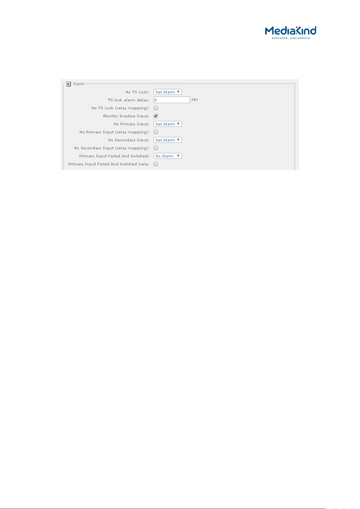
3–45
3.9.3.4. Input Alarms
3.9.3.4.1. Input > General Input Alarms
Figure 3-27 Alarm settings for the Input section
• No TS Lock – Select the alarm condition from the drop-down
menu to be activated when Transport Stream loses lock (Set
Alarm /No Alarm).
• No TS Lock (relay mapping) – Place a check mark in the box
to activate relay mapping for Transport Stream loss of lock
alarm.
• Monitor Inactive Input – Place a check mark in the box to
activate an alarm when there is no signal present at the
inactive Input.
• No Primary Input Lock – Select the alarm condition from the
drop-down menu to be activated when Primary Input loses lock
(Set Alarm /No Alarm).
• No Primary Input Lock (relay mapping) – Place a check
mark in the box to activate relay mapping for Primary Input
loss of lock alarm.
• No Secondary Input Lock – Select the alarm condition from
the drop-down menu to be activated when Secondary Input
loses lock (Set Alarm /No Alarm).
• No Secondary Input Lock (relay mapping) – Place a check
mark in the box to activate relay mapping for Secondary Input
loss of lock alarm.
• Primary Input Failed And Switched – Select the alarm
condition from the drop-down menu to be activated when the
Input Redundancy Mode is enabled and the current input is not
the Primary Input (Set Alarm /No Alarm).
RX8000 Integrated Receiver/Decoders
1553-FGB 101 759 Uen K
www.mediakind.com
• Primary Input Failed And Switched (relay mapping) –
Place a check mark in the box to activate relay mapping for the
Primary Input Failed And Switched alarm.
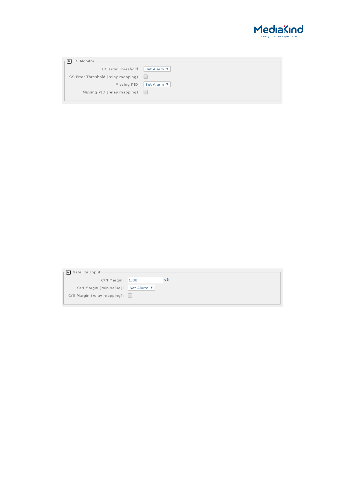
3–46
3.9.3.4.2. Input > TS Monitor Alarms
Figure 3-28 Alarm settings for the Input > TS Monitor section
• CC Error Threshold – Select the alarm condition from the
drop-down menu to be activated when the TS Monitor is
enabled and the PIDs of the selected services in the incoming
transport stream are exhibiting continuity count errors above
the configured threshold (Set Alarm /No Alarm).
• CC Error Threshold (relay mapping) – Place a check mark
in the box to activate relay mapping for the CC Error Threshold
alarm.
• Missing PID – Select the alarm condition from the drop-down
menu to be activated when the TS Monitor is enabled and one
or more of the PIDs from the selected services have not been
detected within the configured period (Set Alarm /No
Alarm).
• Missing PID (relay mapping) – Place a check mark in the
box to activate relay mapping for the Missing PID alarm.
3.9.3.4.3. Input > Satellite Input Alarms (S2 and S2 ACM Input Card Types)
Figure 3-29 Alarm settings for the Input > Satellite Input section applicable to satellite board types 1911, 1928
and 1931
• C/N Margin – Select the alarm condition from the drop-down
menu to be activated when the Carrier-to-Noise margin, set
below, is exceeded (Set Alarm /No Alarm).
• C/N Margin (min value) – Enter the Carrier-to-Noise margin
minimum value in decibels. This is used to trigger the alarm
condition, set above, when exceeded.
• C/N Margin (relay mapping) – Place a check mark in the
box to activate relay mapping for C/N Margin exceeded alarm.
RX8000 Integrated Receiver/Decoders
1553-FGB 101 759 Uen K
www.mediakind.com
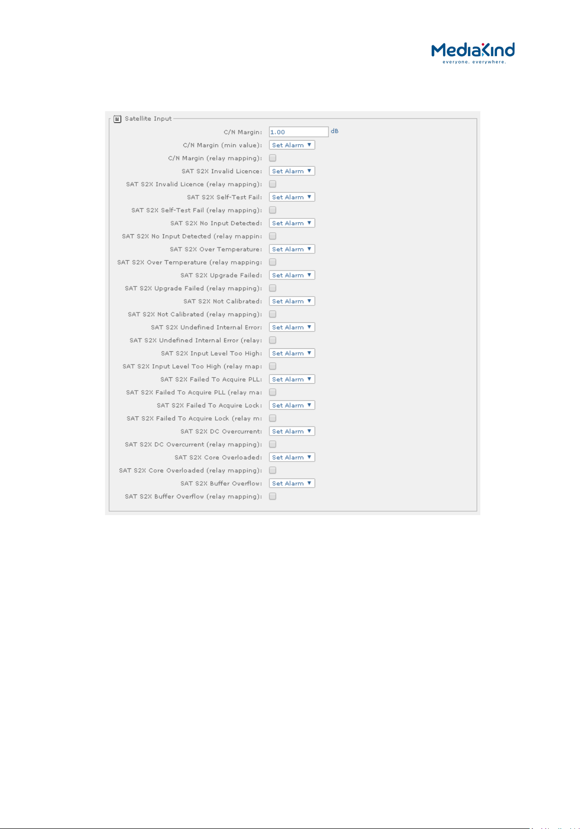
3–47
3.9.3.5. Input > Satellite Input Alarms (S2X Input Card Type)
Figure 3-30 Alarm settings for the Input > Satellite Input section applicable to satellite board type 1935
• C/N Margin – Select the alarm condition from the drop-down
menu to be activated when the Carrier-to-Noise margin, set
below, is exceeded (Set Alarm /No Alarm).
• C/N Margin (min value) – Enter the Carrier-to-Noise margin
minimum value in decibels. This is used to trigger the alarm
condition, set above, when exceeded.
• C/N Margin (relay mapping) – Place a check mark in the
box to activate relay mapping for C/N Margin exceeded alarm.
• SAT S2X Invalid Licence – Select the alarm condition from
the drop-down menu to be activated if this alarm is raised. This
alarm is raised if there is a licence error reported by the DVBS2X card (Set Alarm /No Alarm).
• SAT S2X Invalid Licence (relay mapping) – Place a check
mark in the box to activate relay mapping when this alarm is
raised.
RX8000 Integrated Receiver/Decoders
1553-FGB 101 759 Uen K
www.mediakind.com

3–48
• SAT S2X Self-Test Fail – Select the alarm condition from the
drop-down menu to be activated if this alarm is raised. After
power-on or reset, the DVB-S2X card performs an internal selftest. If this self-test fails it will trigger this alarm (Set Alarm
/No Alarm).
• SAT S2X Self-Test Fail (relay mapping) – Place a check
mark in the box to activate relay mapping when this alarm is
raised.
• SAT S2X No Input Detected – Select the alarm condition
from the drop-down menu to be activated if this alarm is
raised. This alarm is raised if any one of the input related
alarms on the DVB-S2X card are raised (Set Alarm /No
Alarm).
• SAT S2X No Input Detected (relay mapping) – Place a
check mark in the box to activate relay mapping when this
alarm is raised.
• SAT S2X Over Temperature – Select the alarm condition
from the drop-down menu to be activated if this alarm is
raised. This alarm is raised if the internal temperature of the
DVB-S2X card is outside its operating specification (Set Alarm
/No Alarm).
• SAT S2X Over Temperature (relay mapping) – Place a
check mark in the box to activate relay mapping when this
alarm is raised.
• SAT S2X Upgrade Failed – Select the alarm condition from
the drop-down menu to be activated if this alarm is raised. This
alarm is raised when a software upgrade of the
DVB-S2X card has failed. The alarm can only be reset by
executing a successful software upgrade (Set Alarm /No
Alarm).
• SAT S2X Upgrade Failed (relay mapping) – Place a check
mark in the box to activate relay mapping when this alarm is
raised.
• SAT S2X Not Calibrated – Select the alarm condition from
the drop-down menu to be activated if this alarm is raised. This
alarm is raised if there is a calibration error on the DVB-S2X
card (Set Alarm /No Alarm).
• SAT S2X Not Calibrated (relay mapping) – Place a check
mark in the box to activate relay mapping when this alarm is
raised.
• SAT S2X Undefined Internal Error – Select the alarm
condition from the drop-down menu to be activated if this
alarm is raised. This alarm is raised when there an internal
error reported by the DVB-S2X card (Set Alarm /No Alarm).
RX8000 Integrated Receiver/Decoders
1553-FGB 101 759 Uen K
www.mediakind.com
• SAT S2X Undefined Internal Error (relay mapping) –
Place a check mark in the box to activate relay mapping when
this alarm is raised.
• SAT S2X Input Level Too High – Select the alarm condition
from the drop-down menu to be activated if this alarm is
raised. This alarm is raised when the DVB-S2X card
experiences an input level that is too high (Set Alarm /No
Alarm).

3–49
• SAT S2X Input Level Too High (relay mapping) – Place a
check mark in the box to activate relay mapping when this
alarm is raised.
• SAT S2X Failed To Acquire PLL – Select the alarm condition
from the drop-down menu to be activated if this alarm is
raised. This alarm is raised when DVB-S2X card fails to acquire
Physical Layer lock (not applicable for DVB-S) (Set Alarm /No
Alarm).
• SAT S2X Failed To Acquire PLL (relay mapping) – Place a
check mark in the box to activate relay mapping when this
alarm is raised.
• SAT S2X Failed To Acquire Lock – Select the alarm
condition from the drop-down menu to be activated if this
alarm is raised. This alarm is raised when DVB-S2X card fails
to acquire lock (Set Alarm /No Alarm).
• SAT S2X Failed To Acquire Lock (relay mapping) – Place a
check mark in the box to activate relay mapping when this
alarm is raised.
• SAT S2X DC Overcurrent – Select the alarm condition from
the drop-down menu to be activated if this alarm is raised. This
alarm is raised when a DC overcurrent is detected on the input
of the DVB-S2X card (Set Alarm /No Alarm).
• SAT S2X DC Overcurrent (relay mapping) – Place a check
mark in the box to activate relay mapping when this alarm is
raised.
• SAT S2X Core Overloaded – Select the alarm condition from
the drop-down menu to be activated if this alarm is raised. This
alarm is raised when the DVB-S2X card decoder core is too
high loaded (Set Alarm /No Alarm).
• SAT S2X Core Overloaded (relay mapping) – Place a check
mark in the box to activate relay mapping when this alarm is
raised.
• SAT S2X Buffer Overflow – Select the alarm condition from
the drop-down menu to be activated if this alarm is raised. This
alarm is raised when a buffer mismatch occurs in the DVB-S2X
card (Set Alarm /No Alarm).
• SAT S2X Buffer Overflow (relay mapping) – Place a check
mark in the box to activate relay mapping when this alarm is
raised.
RX8000 Integrated Receiver/Decoders
1553-FGB 101 759 Uen K
www.mediakind.com
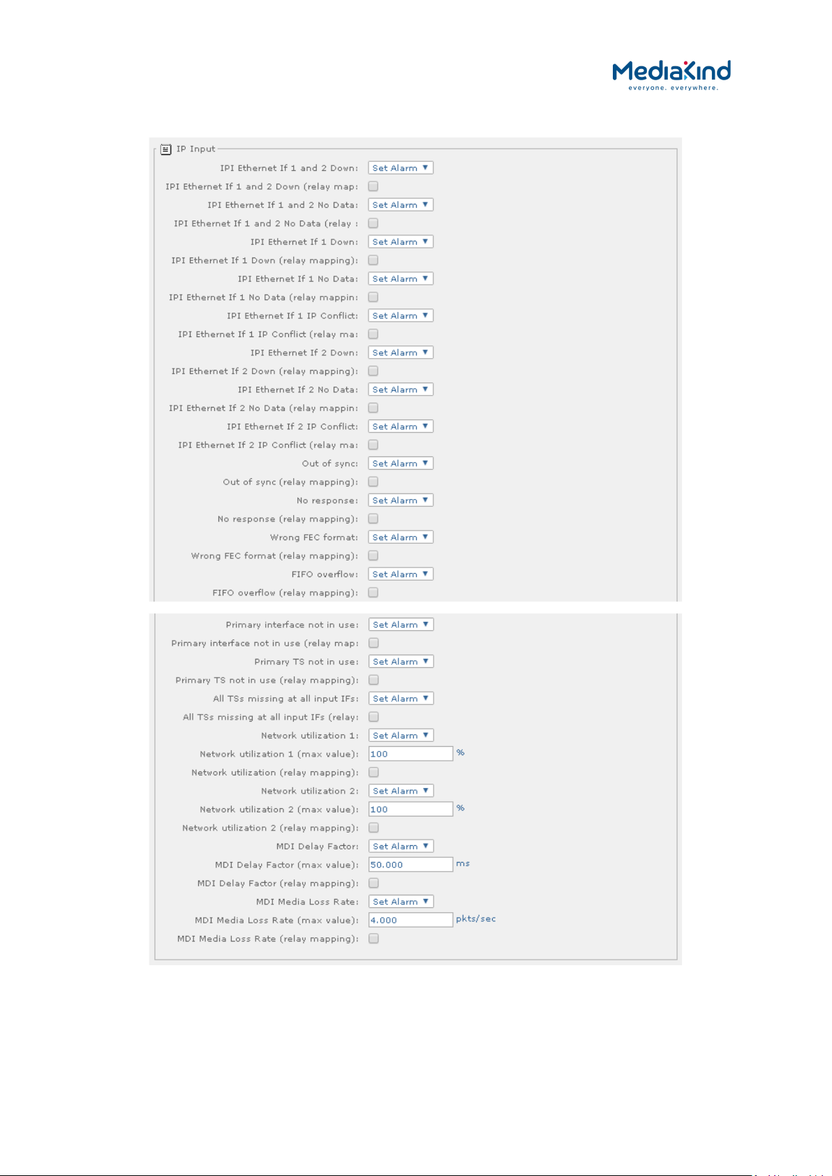
3–50
3.9.3.5.1. Input > IP Input Alarms
Figure 3-31 Alarm settings for the Input > IP Input section
RX8000 Integrated Receiver/Decoders
1553-FGB 101 759 Uen K
www.mediakind.com
• IPI Ethernet IF 1 and 2 Down – Select the alarm condition
from the drop-down menu to be activated when both Ethernet
inputs lose network connectivity (Set Alarm /No Alarm).

3–51
• IPI Ethernet IF 1 and 2 Down (relay mapping) – Place a
check mark in the box to activate relay mapping for Ethernet 1
and 2 down.
• IPI Ethernet If 1 and 2 No Data – Select the alarm
condition from the drop-down menu to be activated when both
Ethernet Transport Stream inputs loose Transport Stream lock
(Set Alarm /No Alarm).
• IPI Ethernet If 1 and 2 No Data (relay mapping) – Place a
check mark in the box to activate relay mapping for Ethernet
input 1 and 2 loss of Transport Stream alarm.
• IPI Ethernet If 1 Down – Select the alarm condition from the
drop-down menu to be activated when Ethernet input port 1
loses network connectivity b.
• IPI Ethernet If 1 Down (relay mapping) – Place a check
mark in the box to activate relay mapping for IPI Ethernet If 1
Down alarm.
• IPI Ethernet If 1 No Data – Select the alarm condition from
the drop-down menu to be activated when Ethernet input port
1 loses Transport Stream data lock (Set Alarm / No Alarm).
• IPI Ethernet If 1 No Data (relay mapping) – Place a check
mark in the box to activate relay mapping IPI Ethernet IF 1 No
Data alarm.
• IPI Ethernet If 1 IP Conflict – Select the alarm condition
from the drop-down menu to be activated when Ethernet input
port 1 senses a conflict of IP address with another device (Set
Alarm / No Alarm).
• IPI Ethernet If 1 IP Conflict (relay mapping) – Place a
check mark in the box to activate relay mapping for IPI
Ethernet If 1 IP Conflict alarm.
• IPI Ethernet If 2 Down – Select the alarm condition from the
drop-down menu to be activated when Ethernet input port 2
loses network connectivity (Set Alarm /No Alarm).
• IPI Ethernet If 2 Down (relay mapping) – Place a check
mark in the box to activate relay mapping for Transport
Stream loss of lock alarm.
• IPI Ethernet If 2 No Data – Select the alarm condition from
the drop-down menu to be activated when Ethernet input port
2 loses Transport Stream data lock (Set Alarm / No Alarm).
• IPI Ethernet If 2 No Data (relay mapping) – Place a check
mark in the box to activate relay mapping for IPI Ethernet If 2
No Data alarm.
RX8000 Integrated Receiver/Decoders
1553-FGB 101 759 Uen K
www.mediakind.com
• IPI Ethernet If 2 IP Conflict – Select the alarm condition
from the drop-down menu to be activated when Ethernet input
port 2 senses a conflict of IP address with another device (Set
Alarm / No Alarm).
• IPI Ethernet If 2 IP Conflict (relay mapping) – Place a
check mark in the box to activate relay mapping for IPI
Ethernet If 2 IP Conflict alarm.
• Out of sync – Select the alarm condition from the drop-down
menu to be activated when the Transport Stream de-

3–52
encapsulation from IP loses sync with the transport packets
(Set Alarm / No Alarm).
• Out of sync (relay mapping) – Place a check mark in the
box to activate relay mapping for out of sync alarm.
• No Response – Select the alarm condition from the drop-
down menu to be activated when the base unit cannot
communicate with the IP input card (Set Alarm / No Alarm).
• No Response (relay mapping) – Place a check mark in the
box to activate relay mapping for no response alarm.
• Wrong FEC format – Select the alarm condition from the
drop-down menu to be activated when the IP card detects that
the incoming IP datagrams have the wrong FEC for the current
configuration (Set Alarm / No Alarm).
• Wrong FEC format (relay mapping) – Place a check mark in
the box to activate relay mapping for wrong FEC format alarm.
• FIFO overflow – Select the alarm condition from the drop-
down menu to be activated when the IP card ‘s input FIFO
overflows (Set Alarm / No Alarm).
• FIFO overflow (relay mapping) – Place a check mark in the
box to activate relay mapping for input FIFO overflow alarm.
• Primary interface not in use – Select the alarm condition
from the drop-down menu to be activated when due to
redundancy switching the primary IP interface port is no longer
being used (Set Alarm / No Alarm).
• Primary interface not in use (relay mapping) – Place a
check mark in the box to activate relay mapping for the
primary interface not in use alarm.
• Primary TS not in use – Select the alarm condition from the
drop-down menu to be activated when due to redundancy
switching the IP inputs primary data connection (multicast
address) is no longer being used (Set Alarm / No Alarm).
• Primary TS not in use (relay mapping) – Place a check
mark in the box to activate relay mapping for primary TS not in
use alarm.
• All TSs missing at all input IFs – Select the alarm condition
from the drop-down menu to be activated when all multicast
streams (primary and secondary) are no longer supplying data
(Set Alarm / No Alarm).
• All TSs missing at all input Ifs (relay mapping) – Place a
check mark in the box to activate relay mapping for TS missing
at all input ifs alarm.
RX8000 Integrated Receiver/Decoders
1553-FGB 101 759 Uen K
www.mediakind.com
• Network utilization 1 – Select the alarm condition from the
drop-down menu to be activated when the network utilization
percentage level on IP interface 1 exceeds the threshold set by
the Network utilization 1 max value (Set Alarm / No
Alarm).
• Network utilization 1 (max value) – Enter the maximum
allowable network utilization (0 to 100%). This is used to
trigger the alarm condition, set above, when exceeded.

3–53
• Network utilization 1 (relay mapping) – Place a check
mark in the box to activate relay mapping for the Network
utilization 1 alarm.
• Network utilization 2 – Select the alarm condition from the
drop-down menu to be activated when the network utilization
percentage level on IP interface 2 exceeds the threshold set by
the Network utilization 2 max value (Set Alarm / No
Alarm).
• Network utilization 2 (max value) – Enter the maximum
allowable network utilization (0 to 100%). This is used to
trigger the alarm condition, set above, when exceeded.
• Network utilization 2 (relay mapping) – Place a check
mark in the box to activate relay mapping for Network
utilization 2 alarm.
• MDI Delay Factor – Select the alarm condition from the drop-
down menu to be activated when the MDI Delay Factor on the
current IP interface exceeds the threshold set by the MDI
Delay Factor max value (Set Alarm / No Alarm).
• MDI Delay Factor (max value) – Enter the maximum
allowable MDI delay factor This is used to trigger the alarm
condition, set above, when exceeded.
• MDI Delay Factor (relay mapping) – Place a check mark in
the box to activate relay mapping for the MDI Delay Factor
alarm.
• MDI Media Loss Rate – Select the alarm condition from the
drop-down menu to be activated when the MDI Media Loss
Rate on the current IP interface exceeds the threshold set by
the MDI Media Loss Rate max value (Set Alarm / No
Alarm).
• MDI Media Loss Rate (max value) – Enter the maximum
allowable MDI loss rate This is used to trigger the alarm
condition, set above, when exceeded.
• MDI Media Loss Rate (relay mapping) – Place a check
mark in the box to activate relay mapping for the MDI Media
Loss Rate alarm.
3.9.3.5.2. Input > IP Input Alarms (RX8200/SWO/IP/IN/SEAMLESS software option)
In addition to the alarms specified in 3.9.3.5.1 Input > IP Input Alarms, the
RX8200/SWO/IP/IN/SEAMLESS software option adds the following extra alarms.
RX8000 Integrated Receiver/Decoders
1553-FGB 101 759 Uen K
www.mediakind.com

3–54
Figure 3-32 Alarm settings for the Input > IP Input section applicable when RX8200/SWO/IP/IN/SEAMLESS
option present
• Seamless Switching Sync Failure – Select the alarm
condition from the drop-down menu to be activated when the
Seamless Protection Switching fails to synchronize. This
indicates that one or both of the two input streams are NOT
locked on the IP input OR the skew between the two IP inputs
exceed the specified maximum of 50 ms. Note that the actual
skew between the two IP inputs is displayed on the GUI – see
“skew” under “seamless Protection Switching”. (Set Alarm /
No Alarm).
• RTP Packet Drop Ratio 1 – Select the alarm condition from
the drop-down menu to be activated when Seamless Protection
Switching mode is enabled and the ratio of RTP Packet
sequence numbers missing over the number of RTP Packets
entering the Seamless Protection block on IP interface Port 1
has exceeded the user defined alarm threshold Max Pkt Drop
Percentage Port 1 (Set Alarm / No Alarm).
• Max Pkt Drop Percentage Port 1 – Enter the maximum
allowable percentage of RTP packets dropped on IP interface
Port 1. This is used to trigger the alarm condition, set above,
when exceeded.
• RTP Packet Drop Ratio 1 (relay mapping) – Place a check
mark in the box to activate relay mapping for the RTP Packet
Drop Ratio 1 alarm.
• RTP Packet Drop Ratio 2 – Select the alarm condition from
the drop-down menu to be activated when Seamless Protection
Switching mode is enabled and the ratio of RTP Packet
sequence numbers missing over the number of RTP Packets
entering the Seamless Protection block on IP interface Port 2
has exceeded the user defined alarm threshold Max Pkt Drop
Percentage Port 2 (Set Alarm / No Alarm).
• Max Pkt Drop Percentage Port 2 – Enter the maximum
allowable percentage of RTP packets dropped on IP interface
Port 2. This is used to trigger the alarm condition, set above,
when exceeded.
RX8000 Integrated Receiver/Decoders
1553-FGB 101 759 Uen K
www.mediakind.com
• RTP Packet Drop Ratio 2 (relay mapping) – Place a check
mark in the box to activate relay mapping for the RTP Packet
Drop Ratio 2 alarm.
• Seamless Switching Excess Skew – Select the alarm
condition from the drop-down menu to be activated when
Seamless Protection Switching mode is enabled and the
measured skew between interface Port 1 and Port 2 has

3–55
exceeded the user defined alarm threshold Excess Skew
alarm threshold (Set Alarm / No Alarm).
• Excess Skew alarm threshold – Enter the maximum
allowable skew threshold in milliseconds. This is used to trigger
the alarm condition, set above, when exceeded.
• Seamless Switching Excess Skew (relay mapping) – Place
a check mark in the box to activate relay mapping for the
Seamless Switching Excess Skew alarm.
3.9.3.5.3. Input > G.703 Input Alarms
Figure 3-33 Alarm settings for the Input > G.703 Input section
• G.703 Input Option Card Alarm – Select the alarm condition
from the drop-down menu to be activated when a failure
condition is raised by the G.703 input card (Set Alarm /No
Alarm).
• G.703 Input Option Card Alarm (relay mapping) – Place a
check mark in the box to activate relay mapping for the G.703
Input Option Card Alarm.
3.9.3.5.4. Input > Terrestrial Input Alarms
Figure 3-34 Alarm settings for the Input > Terrestrial Input section
RX8000 Integrated Receiver/Decoders
1553-FGB 101 759 Uen K
www.mediakind.com
• T2 Option Card SW Fail – Select the alarm condition from the
drop-down menu to be activated when the T2 option card’s
software fails to boot (Set Alarm / No Alarm).
• T2 Option Card SW Fail (relay mapping) – Place a check
mark in the box to activate relay mapping for SW fail.
• MER Margin – Select the alarm condition from the drop-down
menu to be activated when the measured MER Margin from the

3–56
DVB-T2 input card exceeds the user defined threshold MER
Margin (min value) (Set Alarm / No Alarm).
• MER Margin (min value) – Enter the minimum allowable MER
Margin for the DVB-T2 transmission in dB (DVB-T2 card must
be fitted). This is used to trigger the alarm condition, set
above, when exceeded.
• MER Margin (relay mapping) – Place a check mark in the
box to activate relay mapping for MER margin alarm.
• Tuner Temperature – Select the alarm condition from the
drop-down menu to be activated when the tuner temperature
measured from the DVB-T2 input card exceeds the user
defined threshold Tuner Temperature (max value) (Set
Alarm / No Alarm).
• Tuner temperature (max value) – Enter the maximum
allowable tuner temperature for the DVB-T2 card (in °C) This is
used to trigger the alarm condition, set above, when exceeded.
• Tuner temperature (relay mapping) – Place a check mark
in the box to activate relay mapping for the Tuner Temperature
alarm.
• BER – Select the alarm condition from the drop-down menu to
be activated when the Bit Error Rate (BER) measured from the
DVB-T2 input card exceeds the user defined threshold BER
(limit value) (Set Alarm / No Alarm).
• BER (limit value) – Enter the maximum allowable bit error
rate for the DVB-T2 card (in dB) This is used to trigger the
alarm condition, set above, when exceeded.
• BER (relay mapping) – Place a check mark in the box to
activate relay mapping for the BER alarm.
• Antenna Mode: Lock Loss – Select the alarm condition from
the drop-down menu to be activated when the DVB-T2 input
card is configured to measure the power level since this will
disrupt the TS lock state. For more information, refer to section
3.10.6, DVB-T/T2 (OFDM). (Set Alarm / No Alarm).
• Antenna Mode: Lock Loss (relay mapping) – Place a check
mark in the box to activate relay mapping for the Antenna
Mode Lock Loss alarm.
3.9.3.5.5. Input > 8VSB Input Alarms
Figure 3-35 Alarm settings for the Input > 8VSB Input section
RX8000 Integrated Receiver/Decoders
1553-FGB 101 759 Uen K
www.mediakind.com
• SNR – Select the alarm condition from the drop-down menu to
be activated when the Signal to Noise Ratio (SNR) measured
from the 8VSB input card exceeds the user defined threshold
SNR (min value) (Set Alarm / No Alarm).

3–57
• SNR (min value) – Enter the minimum Signal to Noise Ratio
value in decibels (dB). This is used to trigger the alarm
condition, set above, when exceeded
• SNR (relay mapping) – Place a check mark in the box to
activate relay mapping for the SNR alarm.
3.9.3.6. Service Alarms
3.9.3.6.1. Service > Conditional Access Alarms
Figure 3-36 Alarm settings for the Service > Conditional Access section
• CA Error – Select the alarm condition from the drop-down
menu to be activated when a Conditional Access error is
detected. To determine the cause of the CA Error alarm, refer
to Table 3-10 under section Error! Reference source not
found. for Error! Reference source not found.. (Set Alarm
/No Alarm).
• CA Error (relay mapping) – Place a check mark in the box to
activate relay mapping for Conditional Access error.
3.9.3.6.2. Service > Video Alarms
Figure 3-37 Alarm settings for the Service > Video section
• Video Not Running – Select the alarm condition from the
drop-down menu to be activated when the attempted video
decode is not running (Set Alarm /No Alarm).
• Video Not Running (relay mapping) – Place a check mark
in the box to activate relay mapping for video not running.
• Unsupported Video Resolution Detected – Select the alarm
condition from the
drop-down menu to be activated when the attempted video
decode does not support the detected video resolution (Set
Alarm /No Alarm).
RX8000 Integrated Receiver/Decoders
1553-FGB 101 759 Uen K
www.mediakind.com
• Unsupported Video Resolution Detected (relay mapping)
– Place a check mark in the box to activate relay mapping for
the Unsupported Video Resolution Detected alarm.
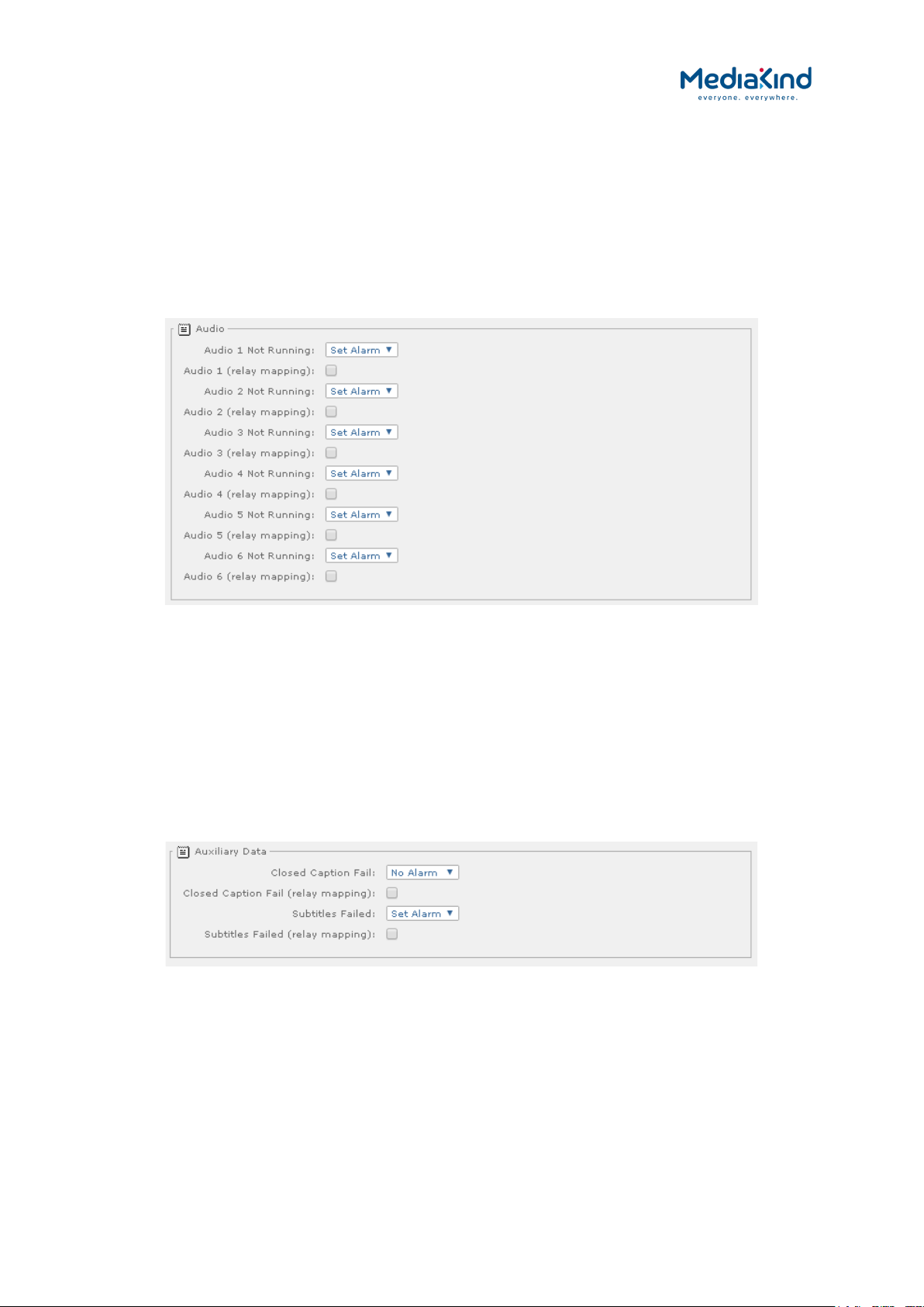
3–58
• Frame Sync Out of Sync – Select the alarm condition from
the drop-down menu to be activated when Frame Sync is
enabled but is not synchronized to the current video frame rate
or no signal is detected (Set Alarm /No Alarm).
• Frame Sync Out of Sync (relay mapping) – Place a check
mark in the box to activate relay mapping for the Frame Sync
Out of Sync alarm.
3.9.3.6.3. Service > Audio Alarms
Figure 3-38 Alarm settings for the Service > Audio section
• Audio Decoder 1/2/3/4/5/6 – Select the alarm condition
from the drop-down menu to be activated when Audio Decoder
1/2/3/4/5/6 is not running (Set Alarm /No Alarm).
• Audio Decoder 1/2/3/4/5/6 (relay mapping) – Place a
check mark in the box to activate relay mapping for Audio
Decoder 1/2/3/4/5/6 not running.
3.9.3.6.4. Service > Auxiliary Data Alarms
Figure 3-39 Alarm settings for the Service > Auxiliary Data section
• Closed Caption Fail – Select the alarm condition from the
drop-down menu to be activated when closed caption fails (Set
Alarm /No Alarm).
RX8000 Integrated Receiver/Decoders
1553-FGB 101 759 Uen K
www.mediakind.com
• Closed Caption Fail (relay mapping) – Place a check mark
in the box to activate relay mapping for closed caption fails.
• Subtitles Failed - Select the alarm condition from the drop-
down menu to be activated when DVB or Teletext subtitles fails
(Set Alarm /No Alarm).

3–59
• Subtitles Failed (relay mapping) – Place a check mark in
the box to activate relay mapping for subtitle fails.
3.9.3.6.5. Service > 422 Decoder Card Alarms
Figure 3-40 Alarm settings for the Service > 422 Decoder Card section
• TS not locked on 422 card – Select the alarm condition from
the drop-down menu to be activated when there is an issue
with the Transport Stream input to the 4:2:2 Decoder Option
card (Set Alarm /No Alarm).
• TS not locked on 422 card (relay mapping) – Place a check
mark in the box to activate relay mapping for TS not locked on
422 card error.
• Decoder not ready on 422 card – Select the alarm condition
from the drop-down menu to be activated when the video
decoder on the 4:2:2 Decoder Option card is not ready to
operate (Set Alarm /No Alarm).
• Decoder not ready on 422 card (relay mapping) – Place a
check mark in the box to activate relay mapping for Decoder
not ready on 422 card error.
• Decoder error on 422 card – Select the alarm condition from
the drop-down menu to be activated when the video decoder
on the 4:2:2 Decoder Option card is in an error state (Set
Alarm /No Alarm).
• Decoder error on 422 card (relay mapping) – Place a
check mark in the box to activate relay mapping for Decoder
error on 422 card error.
• 422 Decoder not locked to system clock – Select the alarm
condition from the
drop-down menu to be activated when the decoder 422 card is
free running
(i.e. Not locked to the system clock) (Set Alarm /No Alarm).
RX8000 Integrated Receiver/Decoders
1553-FGB 101 759 Uen K
www.mediakind.com
• 422 Decoder not locked to system clock (relay mapping)
– Place a check mark in the box to activate relay mapping for
422 Decoder not locked to system clock alarm.
• Code version error on 422 card – Select the alarm condition
from the drop-down menu to be activated when the code
version loaded on the 4:2:2 Decoder Option card is not
compatible with the base unit code version. For the 3
rd
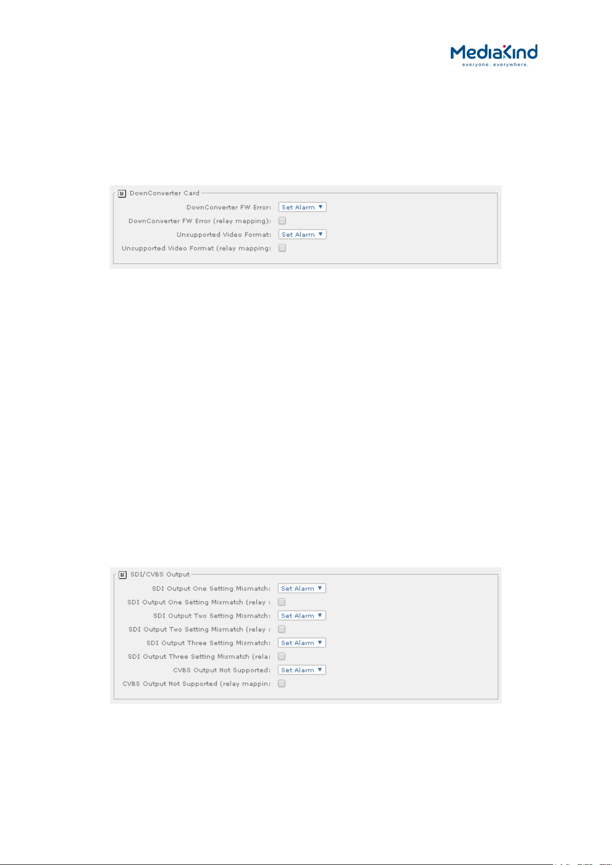
3–60
Generation 4:2:2 Decoder Option card, the minimum
supported code version is 3.0 (Set Alarm /No Alarm).
• Code version error on 422 card (relay mapping) – Place a
check mark in the box to activate relay mapping for Code
version error on 422 card error.
3.9.3.6.6. Service > Down Converter Card Alarms
Figure 3-41 Alarm setting for Service > Down Converter Card section
• DownConverter FW Error – Select the alarm condition from
the drop-down menu
to be activated when the high quality down-converter FPGA
interface presents an error (Set Alarm /No Alarm).
• DownConverter FW Error (relay mapping) – Place a check
mark in the box to activate relay mapping for down-converter
firmware error.
• Unsupported Video Format - Select the alarm condition from
the drop-down menu to be activated when the high quality
down-conversion card detects an unsupported video format
(Set Alarm /No Alarm).
• Unsupported Video Format (relay mapping) – Place a
check mark in the box to activate relay mapping for
unsupported video format.
3.9.3.7. Output Alarms
3.9.3.7.1. Output > SDI/CVBS Output Alarms
Figure 3-42 Alarm settings for Output > SDI/CVBS section
RX8000 Integrated Receiver/Decoders
1553-FGB 101 759 Uen K
www.mediakind.com
• SDI Output One Setting Mismatch - Select the alarm
condition from the drop-down menu to be activated when
outgoing video standard is not compatible with the SDI setting
on Output One (Set Alarm /No Alarm).
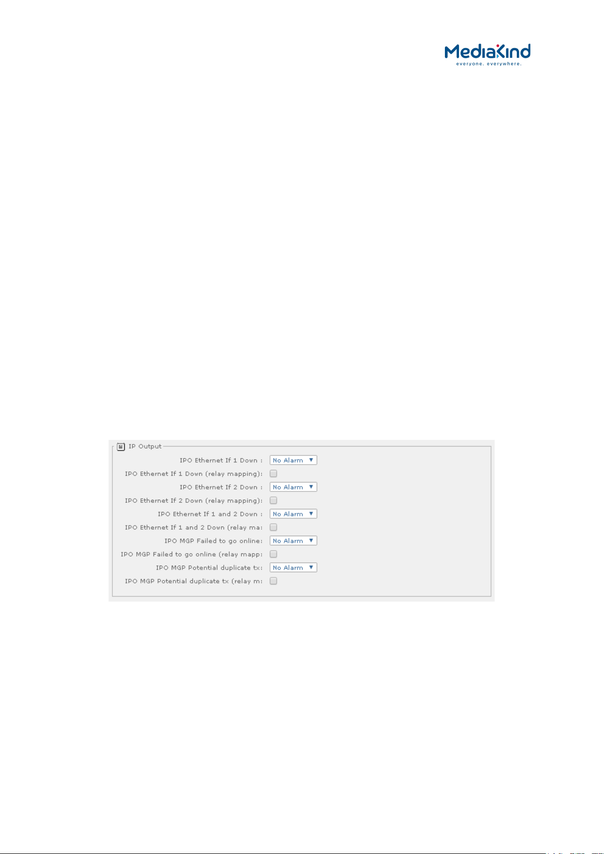
3–61
• SDI Output One Setting Mismatch (relay mapping) –
Place a check mark in the box to activate relay mapping for the
SDI Output One Setting Mismatch alarm.
• SDI Output Two Setting Mismatch - Select the alarm
condition from the drop-down menu to be activated when
outgoing video standard is not compatible with the SDI setting
on Output Two (Set Alarm /No Alarm).
• SDI Output Two Setting Mismatch (relay mapping) –
Place a check mark in the box to activate relay mapping for the
SDI Output Two Setting Mismatch alarm.
• SDI Output Three Setting Mismatch - Select the alarm
condition from the drop-down menu to be activated when
outgoing video standard is not compatible with the SDI setting
on Output Three (Set Alarm /No Alarm).
• SDI Output Three Setting Mismatch (relay mapping) –
Place a check mark in the box to activate relay mapping for the
SDI Output Three Setting Mismatch alarm.
• CVBS Output Not Supported - Select the alarm condition
from the drop-down menu to be activated when there is an
unsupported frame rate on the CVBS output i.e. 30 Hz or 60 Hz
(Set Alarm /No Alarm).
• CVBS Output Not Supported (relay mapping) – Place a
check mark in the box to activate relay mapping for the CVBS
Output Not Supported alarm.
3.9.3.7.2. Output > IP Output Alarms
Figure 3-43 Alarm Settings for Output > IP Output section
• IPO Ethernet If 1/2 Down – Select the alarm condition from
the drop-down menu to be activated when there is no signal at
IPO Ethernet 1/2 (Set Alarm /No Alarm).
RX8000 Integrated Receiver/Decoders
1553-FGB 101 759 Uen K
www.mediakind.com
• IPO Ethernet If 1/2 Down (relay mapping) – Place a
check mark in the box to activate relay mapping for no signal
at IPO Ethernet 1/2.
• IPO Ethernet If 1 and 2 Down – Select the alarm condition
from the drop-down menu to be activated when there is no
signal at IPO Ethernet 1 and 2 (Set Alarm /No Alarm).

3–62
• IPO Ethernet If 1 and 2 Down (relay mapping) – Place a
check mark in the box to activate relay mapping for no signal
at IPO Ethernet 1 and 2.
• IPO MGP Failed to go online – Select the alarm condition
from the drop-down menu to be activated when there the IP
output cannot go online (transmit multicast data) in an MGP
enabled system (Set Alarm /No Alarm).
• IPO MGP Failed to go online (relay mapping) – Place a
check mark in the box to activate relay mapping for MGP failed
to go online.
• IPO MGP Potential duplicate tx – Select the alarm condition
from the drop-down menu to be activated when there the IP
output detects a clashing multicast on an MGP enabled system
(Set Alarm /No Alarm).
• IPO MGP Potential duplicate tx (relay mapping) – Place a
check mark in the box to activate relay mapping for MGP
potential duplicate TS.
3.9.3.7.3. Output > Filtering Alarms
Figure 3-44 Alarm Settings for Output > Filtering section
RX8000 Integrated Receiver/Decoders
1553-FGB 101 759 Uen K
www.mediakind.com
• Filter Output Overflow – Select the alarm condition from the
drop-down menu to be activated when the multi-service filter
block detects an overflow within its buffers (Set Alarm /No
Alarm).
• Filter Output Overflow (relay mapping) – Place a check
mark in the box to activate relay mapping for the Filter Output
Overflow alarm.
• Service Split Overrate – Select the alarm condition from the
drop-down menu to be activated when the CBR Bitrate for a
split service is not high enough for the minimum filtered TS
data rate for the split service (Set Alarm /No Alarm).
• Service Split Overrate (relay mapping) – Place a check
mark in the box to activate relay mapping for the Service Split
Overrate alarm.
• Overrate Protection – Select the alarm condition from the
drop-down menu to be activated when the MSF Overrate
Protection Limit has been reached (Set Alarm /No Alarm).
 Loading...