


Configuration Notes 281
Mediatrix 3000 Digital Gateway
Corporate Network
June 21, 2011
Proprietary
2011 Media5 Corporation

Configuration Notes 281
Table of Contents
Configuration Notes 281 ................................................................. 1
Introduction ............................................................................................................................................................................... 3
Mediatrix 3000 Digital Gateway Overview ................................................................................................................................ 3
Deployment Scenario................................................................................................................................................................ 4
Description.................................................................................................................................................................. 4
Objectives ................................................................................................................................................................... 4
Assumptions ............................................................................................................................................................... 5
Steps .......................................................................................................................................................................... 5
Configuration of the Mediatrix 3000 Digital Gateway ................................................................................................................ 6
Physical Connection of the Mediatrix 3000 DG to the Network
and PSTN ................................................................................................................................................................... 6
IP Address Discovery or Configuration ....................................................................................................................... 6
Web Interface Access ................................................................................................................................................. 7
SIP Configuration ....................................................................................................................................................... 8
ISDN Configuration ..................................................................................................................................................... 8
Call Routing Configuration ........................................................................................................................................ 12
Basic Call Establishment .......................................................................................................................................... 22
Further Information and Configuration .................................................................................................................................... 23
Appendix A - Restarting a Service .......................................................................................................................................... 24
Page 2 of 25

Model
Interfaces
VoIP Call Capacity
Mediatrix 3404
5 BRI ports
up to 8
Mediatrix 3408
10 BRI ports
up to 16
Mediatrix 3531
1xT1-PRI interface
up to 23
Mediatrix 3532
2xT1-PRI interface
up to 46
Mediatrix 3631
1xE1-PRI interface
up to 30
Mediatrix 3632
2xE1-PRI interface
up to 60
Configuration Notes 281
Introduction
This document outlines the configuration steps to set up a Mediatrix® 3000 digital gateway to act as a gateway with the
PSTN.
Mediatrix 3000 Digital Gateway Overview
These configuration notes apply to the Mediatrix 3000 Series digital
gateway products. The Mediatrix 3000 Series digital gateways allow
enterprises to lower communications costs over any IP link. The
platform supports ISDN E1 and T1 PRI telephony interfaces, as well
as ISDN BRI interfaces. They provide an ideal solution for enterprise
voice applications or for connecting to a service provider’s broadband
access.
Mediatrix® 3000 digital gateways are fully scalable in terms of number
of ports and functionalities. They currently come in the following
models:
The Mediatrix digital gateways link any standard ISDN E1/T1 PRI or BRI connection to the IP network and deliver the clarity
of toll quality voice for a comprehensive VoIP solution.
T.38 FoIP, fax bypass, and modem bypass capabilities ensure that the Mediatrix digital gateways seamlessly transport voice
and data services. The Mediatrix digital gateways offer flexibility and scalability for VoIP network integration and low
bandwidth voice.
With configurable NT/TE PRI ports, call-switching and user programmable call routing (including caller/called ID), Mediatrix
digital gateways integrate smoothly into existing PBX and PSTN networks.
Key Features:
Voice Routing.
Fax over IP support, including T.38.
Proven voice algorithms implemented on dedicated DSP for enhanced voice quality.
Up to 60 simultaneous calls.
SNMPv3 and web management.
Configuration file encryption.
Automatic firmware and configuration file download.
PSTN Bypass feature (BRI models only).
Page 3 of 25

Configuration Notes 281
Deployment Scenario
Description
This configuration note is a step-by-step guide to set up one Mediatrix 3632 Series digital gateway to act as a gateway with
the PSTN in a corporate network. The Mediatrix 3632 is used to connect an existing VoIP network to the PSTN. The
configuration starts with the Mediatrix 3632 default configuration but can be easily customized for the 3631, 3531, and 3532,
so from now on, the device will be referred to as the Mediatrix 3000 DG (Digital Gateway). The following is the network
topology to which we will refer in our sample deployment.
Figure 1 - Network Topology
Note: The network addresses and phone numbers shown above are sample values that will most probably vary in your
specific setup. In the following pages, when referring to such a sample value, it will be visually outlined (e.g., 192.168.9.194),
so whenever you see parameters outlined in that fashion, you should replace them with the values that are appropriate for
your specific setup.
Objectives
The steps described in the following pages will show you how to setup the Mediatrix 3000 DG so it can:
A. receive calls from the PSTN and route them to the VoIP network (e.g., phone 2 calls phone 1):
1. a user picks up an ISDN phone and dials the number of a line connected to the Mediatrix 3000 DG.
2. the PSTN routes the call to the Mediatrix 3000 DG.
3. the Mediatrix 3000 DG routes the call to the appropriate Mediatrix 1102, removing necessary prefix (area
code 030) from the called number.
4. the Mediatrix 1102 makes the appropriate analog phone ring.
5. a user picks up the analog phone and the call is established.
B. receive calls from the VoIP network and route them to the PSTN on one of the PRI lines connected to the Mediatrix
3000 DG (e.g. phone 1 calls phone 2):
1. a user picks up an analog phone and dials a number.
2. the appropriate Mediatrix 1102 routes the call to the Mediatrix 3000 DG.
3. the Mediatrix 3000 DG decides to which ISDN PRI interface route this call.
Page 4 of 25

Configuration Notes 281
4. the Mediatrix 3000 DG adds the necessary prefix (area code 030) to the dialed phone number before
routing the call to the PSTN.
5. the PSTN makes the appropriate ISDN phone ring.
6. a user picks up the ISDN phone and the call is established.
Assumptions
This configuration note focuses on configuring the Mediatrix 3000 DG and assumes that:
the SIP server’s default route’s destination is the Mediatrix 3000 DG, e.g., when a number dialed on an analog phone is
unknown, the call is sent to the Mediatrix 3000 DG.
the left-hand side of the VoIP network setup is functional (Mediatrix 1102, analog phones, SIP server), and the SIP
users are correctly registered to the SIP server.
Steps
This configuration note will guide you through the following steps:
1. Physical connection of the Mediatrix 3000 DG to the IP network and PSTN.
2. IP address discovery or configuration.
3. Web interface access.
4. SIP configuration.
5. ISDN configuration.
6. Call routing configuration.
7. Basic call establishment.
Page 5 of 25

Configuration Notes 281
Configuration of the Mediatrix 3000 Digital Gateway
Physical Connection of the Mediatrix 3000 DG to the Network and PSTN
Please refer to the Mediatrix 3000 DG Quick Start booklet (packaged with the Mediatrix 3000 DG) for instructions on
hardware installation.
The Mediatrix 3000 DG Quick Start booklet can also be found online on the Mediatrix Download Portal at
https://support.mediatrix.com/DownloadPlus/Download.asp.
IP Address Discovery or Configuration
The purpose of this section is to be able to contact the Mediatrix 3000 DG’s management interface to start with unit
configuration.
Once the physical connection is complete and the Mediatrix 3000 DG is powered up, the first thing to do is find out the IP
address the Mediatrix 3000 DG is using. The Mediatrix 3000 DG’s WAN IP address can be set either dynamically or
statically. The default behaviour of the Mediatrix 3000 DG is to try to obtain a dynamic IP address through DHCP.
You can also access the Mediatrix 3000 DG through its private LAN interface.
Dynamic WAN IP Address Discovery
Before connecting the Mediatrix 3000 DG to the network, Mediatrix strongly suggests that you reserve an IP address in your
DHCP server for the unit you are about to connect. DHCP servers reserve IP addresses for specific devices by using a
unique identifier for each device. The Mediatrix 3000 DG’s unique identifier is its media access control (MAC) address. The
MAC address appears on the label located on the bottom side of the unit.
If you have not reserved an IP address, you can discover which IP address has been assigned to the Mediatrix 3000 DG by
either:
consulting your DHCP server’s logs to find out details on the DHCP lease that was given to the Mediatrix 3000 DG.
using a network packet sniffer (e.g., Ethereal) to examine the DHCP messages exchanged between the Mediatrix 3000
DG and your DHCP server while the Mediatrix 3000 DG boots up.
Default WAN Static IP Address Configuration
If there is no DHCP server in your network, then the WAN IP address can be configured statically. The first thing to do is set
the Mediatrix 3000 DG to its known default static IP address. You can do this by using the Mediatrix 3000 DG’s partial reset
feature (see the section Further Information and Configuration for more details).
1. Once the Mediatrix 3000 DG has finished booting up (the Power LED is lit, not blinking), insert a small, unbent
paper clip into the RESET/DEFAULT hole located at the rear of the Mediatrix 3000 DG and press the
RESET/DEFAULT button. The Power LED will start blinking, and after a few seconds, all the LEDS will start
blinking. Release the paper clip after all the LEDs start blinking and before they all stop blinking (between 7-11
seconds).
After a partial reset is performed, the Mediatrix 3000 DG’s WAN connection uses the default 192.168.0.1 IP address. From
now on, you can optionally change the Mediatrix 3000 DG’s IP address (see section Further Information and Configuration
for more details).
LAN Interface Access
The Mediatrix 3000 DG’s default LAN IP address is 192.168.0.10.
Page 6 of 25

Configuration Notes 281
Web Interface Access
The purpose of this section is to log in to the Mediatrix 3000 DG’s web interface.
The Mediatrix 3000 DG’s web interface may be used to view the status of the Mediatrix 3000 DG and set its numerous
parameters.
1. In your web browser’s address field, type 192.168.9.194 (or the address of the Mediatrix 3000 DG). The PC you
use must be connected to the same subnet as the Mediatrix 3000 DG or to a network where it can reach the
Mediatrix 3000 DG’s IP address. The following window appears:
2. Enter the user name public. Leave the Password field empty.
3. Click Login.
You now have access to the Mediatrix 3000 DG’s configuration web interface.
Page 7 of 25

Configuration Notes 281
SIP Configuration
The purpose of this section is to setup the Mediatrix 3000 DG to use your SIP server for registration and call routing.
The SIP configuration tells the Mediatrix 3000 DG which SIP servers, parameters, and phone numbers to use. The following
steps configure the Mediatrix 3000 DG as illustrated in the sample network topology.
1. Click the SIP menu, then the Servers sub-menu. The following window appears:
2. Set the Registrar Host field to the address of the central SIP Server 192.168.9.201.
3. Set the Proxy Host field to the address of the central SIP Server 192.168.9.201.
4. Click Submit to save the configuration changes. The Mediatrix 3000 DG is now configured to use your SIP server.
5. OPTIONAL STEP: if your SIP server requires SIP authentication, further configuration steps are necessary so the
Mediatrix 3000 DG has all the needed information to authenticate to the server (see the section Further
Information and Configuration for more details).
ISDN Configuration
The purpose of this section is to configure the Mediatrix 3000 DG’s ISDN PRI interfaces in Terminal mode (TE) for an E1 line
type. The PSTN line to which the Mediatrix 3000 DG is connected must be in Network mode (NT). If your setup differs,
please refer to the section Further Information and Configuration for more details.
The ISDN configuration tells the Mediatrix 3000 DG how its ISDN PRI interfaces should behave. You must configure the
ISDN parameters of the Mediatrix 3000 DG digital gateways for each interface you intend to use.
Page 8 of 25

Configuration Notes 281
1. Click the ISDN menu, then the Primary Rate Interface sub-menu. The following window appears:
2. Select the interface for which you want to apply the changes in the Select Interface drop-down menu. Depending
on the model of Mediatrix 3000 DG you are using, you may have 1 or 2 interfaces available in the drop-down
menu.
Page 9 of 25

Configuration Notes 281
3. In the Interface Configuration section, set the Endpoint Type field to TE. Leave all other parameters to their default
values.
NOTE: The Line Coding, Line Framing, and Signaling Protocol fields are left to common default values here.
However, they must be compatible with your setup. If your setup differs, please refer to the section Further
Information and Configuration for more details.
4. Click Submit to apply the configuration changes made to this interface.
5. If you have modified values, the parameters that have just been configured require a restart of the ISDN service. A
service is a logical group of features. Restarting a service is a required mechanism for certain elements in the
configuration. However, you can finish with the ISDN configuration steps before doing that. Once the ISDN
configuration is ready, follow the instructions from Appendix A - Restarting a Service to restart the ISDN service
as required.
Page 10 of 25

Configuration Notes 281
6. Repeat steps 2 to 4 for all of the ISDN PRI interfaces listed in the Select Interface field.
7. Restart the ISDN service as described in Appendix A - Restarting a Service.
8. To confirm that the ISDN configuration is completed and compatible with the rest of your setup, click the Status
sub-menu. The following window appears:
The Physical Link and Signaling status fields of each of the ISDN PRI interfaces configured should be Up. If they
are not, please review the configuration steps from this section of the document and make sure they have been
applied correctly and are compatible with your setup. Please refer to the section Further Information and
Configuration for more details.
Page 11 of 25

Configuration Notes 281
Call Routing Configuration
The purpose of this section is to configure the Mediatrix 3000 DG’s call router so it can route calls to/from the VoIP network
and the PSTN as described in the Deployment Scenario section.
You must configure the call router parameters of the Mediatrix 3000 DG digital gateways so that the calls can properly
terminate. Remember that the purpose of this configuration note is to achieve the sample deployment scenario shown in
Figure 1. Your specific setup may vary.
Planning the Call Router
The goal of planning the Call router configuration is to summarize the rules incoming calls will follow when passing through
the Mediatrix 3000 DG.
This is:
Call sources and destinations.
Calls allowed and rejected.
Call properties manipulations.
All routing possibilities.
Before going further with the configuration steps, you should refer back to the two types of calls described in the Deployment
Scenario section.
The most basic call scenario implies at least the configuration of Routes. In the current deployment scenario, you will also
configure Mappings to support Step 3 of call scenario A, and a Hunt Group to support Step 3 of call scenario B defined in the
Deployment Scenario section (see Further Information and Configuration for more details).
A Route is a virtual connection made inside the Mediatrix 3000 DG between call sources and destinations.
Routes are part of the Mediatrix 3000 DG’s Route table. When a call comes in, the Mediatrix 3000 DG uses its
Route table to decide to which destination the call must be forwarded.
A Hunt Group is a virtual entity that regroups different call destinations into one group. This entity can then be
used as a call destination in a Route. When an incoming call is routed to a Hunt, the Hunt group selects one of
its available destinations to route the call.
A Mapping is a transformation that can be applied to a call when it goes through one of the Mediatrix 3000
DG’s routes, according to various criteria. It can be used, for example, to apply changes to the call’s dialled
phone number.
Page 12 of 25

Configuration Notes 281
Configuring the Call Router
Hunt Group
The purpose of this subsection is to configure a Hunt Group in the Mediatrix 3000 DG, so it can be later used as a route’s
destination.
In the current scenario, you will use a Hunt Group to group both of the Mediatrix 3632’s ISDN PRI interfaces as one virtual
call destination.
1. Click the Telephony menu, then the Call Routing Config sub-menu. The following window appears.
2. Locate the Hunt section at the bottom of the window.
Page 13 of 25

Configuration Notes 281
3. Click the button at the bottom right of the Hunt section. The following window appears.
To create a Hunt Group:
4. Set the Name field to hunt_PSTN.
5. Use the Suggestion drop-down list to select and add the possible destinations that will be part of the Hunt Group.
6. Following the Deployment Scenario, select one by one both of the Mediatrix 3000 DG’s ISDN PRI interfaces (isdn-
Slot2/E1T1, which corresponds to port E1/T1 on SLOT 2 and isdn-Slot3/E1T1, which corresponds to port E1/T1
on SLOT 3). The interfaces will be automatically added as destinations for that Hunt Group.
Page 14 of 25

Configuration Notes 281
7. Leave the other fields with their default value.
8. Verify whether or not the ISDN interfaces have been successfully added to the configuration by checking the
Destinations field, then click Submit to apply changes and save the new Hunt Group.
Page 15 of 25

Configuration Notes 281
9. Your are brought back to the Call Routing Config sub-menu. You can see the Hunt Group you have just created
in the Hunt section.
You can also see a yellow Yes warning you that the configuration has been modified but not applied (i.e., the Call
Routing Status differs from the Call Routing Config). The Call Routing Config sub-menu is a working area where
you build up a Call Router configuration. While you work in this area, the configured parameters are saved but not
applied (i.e., they are not used to process incoming calls). The yellow Yes flag warns you that the configuration has
been modified but is not applied. You will apply the configuration later when it is complete.
Mappings
The purpose of this subsection is to configure Mappings in the Mediatrix 3000 DG, so they can be referred to later when
creating routes that need to add/remove a prefix from called phone numbers.
In the current scenario, when calls are routed from the PSTN to SIP, the prefix 030 (area code) needs to be removed from
the called number. As well, when calls are routed from SIP to the PSTN, the prefix 030 needs to be added to the called
phone number. You will use Mappings to perform these transformations on the called phone number.
The Mappings are described by two entities in the Mediatrix 3000 DG: Mapping Types and Mapping Expressions. This
allows to create virtual Mapping “tables”, where a Mapping Type defines the criteria a call must fulfill to enter the table, and
the associated Mapping Expressions describe specific transformation rows in the table.
The most basic Mapping table consists in one Mapping Type and one associated Mapping Expression. In the current
scenario, you will create two basic Mapping tables.
1. Locate the Mapping Type section.
2. Click the button at the bottom right of the Mapping Type section. The following window appears.
To create a Mapping Type that applies to incoming calls from the PSTN and alters the called E.164 phone number,
proceed as follows:
3. Set the Name field to From_PSTN.
4. Set the Criteria field to Called E164 using the drop-down list.
Page 16 of 25

Configuration Notes 281
5. Set the Transformation field to Called E164 using the drop-down list.
6. Click Submit And Insert Expression to apply changes, save the new Mapping Type, and proceed to enter new
Mapping Expressions associated with the Mapping Type just created. The following window appears.
7. To create a Mapping Expression that removes the prefix 030 from dialed phone numbers that start with 030, set
the Criteria field to 030(.+) and the Transformation field to \1.
This mapping expression applies its transformation to any called E.164 phone number starting with 030. The
transformation consists in removing the 030 prefix from the called E.164 phone number. If the phone numbers in
your specific scenario differ, you can modify the contents of the Criteria and Transformation fields to suit your
needs. These fields use the regular expressions syntax (see the section Further Information and Configuration for
more details).
8. Click Submit to apply changes and save the new Mapping Expression.
9. Repeat steps 2 to 8 to create an additional Mapping Type and Mapping Expression. These apply to outgoing calls
to the PSTN and add the prefix 030 to dialed phone numbers. Use the following field values.
a. Mapping Type: set the Name field to To_PSTN, the Criteria field to Called E164 and the Transformation
field to Called E164.
Page 17 of 25

Configuration Notes 281
b. Mapping Expression: set the Criteria field to .+ and the Transformation field to 030\0.
10. After completing all the Mapping creation steps, you will see your two Mapping Types and two Mapping
Expressions. You will also see the yellow Yes warning you that the configuration has been modified but not
applied (i.e., the Call Routing Status differs from the Call Routing Config).
Page 18 of 25

Configuration Notes 281
Route
The purpose of this subsection is to configure the Mediatrix 3000 DG so it makes virtual “connections” between call sources
and destinations, using existing Mappings and Hunt Groups as needed.
1. Locate the Route section at the top of the window.
2. Click the button at the bottom right of the Route section. The following window appears.
3. To create a route from SIP (sip-default) to the PSTN (hunt_PSTN):
o set the Source field to sip-default.
o set the Destination field to hunt-hunt_PSTN.
o add the mapping To_PSTN to the Mappings field.
You can use the three fields’ associated Suggestion drop-down list to help you fill them. This route will satisfy call
scenario B described in section Deployment Scenario, where phone 1 calls phone 2.
Page 19 of 25

Configuration Notes 281
4. Click Submit to apply changes and save the new route.
5. You are brought back to the Call Routing Config sub-menu. You can see the route you just created in the Route
section. You can also see the yellow Yes warning you that the configuration has been modified but not applied
(i.e., the Call Routing Status differs from the Call Routing Config).
6. Repeat steps 2 to 5 twice to create two additional routes. These new routes will satisfy call scenario A described in
Deployment Scenario, where phone 2 calls phone 1:
o one from Source isdn-Slot2/E1T1 to Destination sip-default using Mapping From_PSTN, and
o one from Source isdn-Slot3/E1T1 to Destination sip-default using Mapping From_PSTN.
Page 20 of 25

Configuration Notes 281
7. After completing all the route configuration steps, you will see your three routes.
8. Click Apply. This applies all the parameters from Call Routing Config to the system. You can also see that the
yellow Config Modified yes flag is cleared.
Page 21 of 25
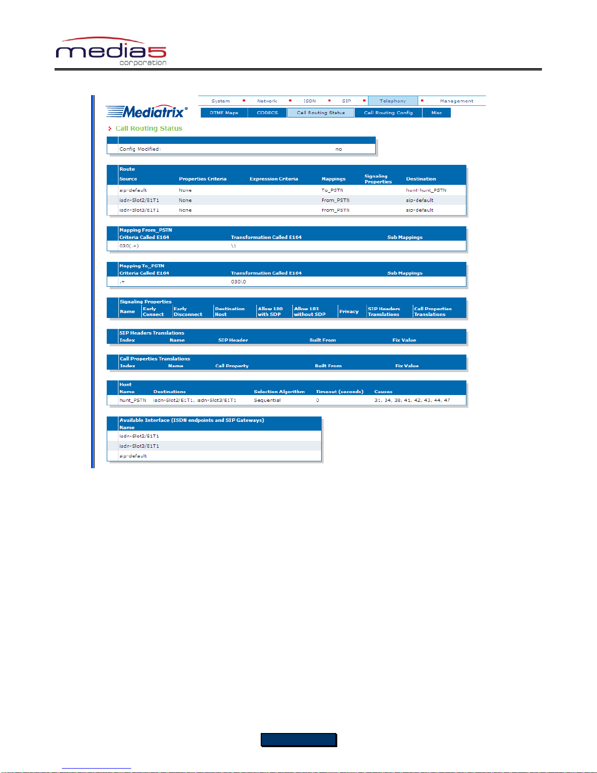
Configuration Notes 281
9. The call routing parameters can be seen in the Call Routing Status window.
The configuration note has prepared the system to perform calls in both directions.
Basic Call Establishment
Once this configuration procedure is completed, you are ready to start making basic calls through your new Mediatrix 3000
DG, providing that the rest of your network’s setup is configured properly.
Perform Basic Call (Scenario A)
Pickup phone number 2.
Dial 030 695 550.
Phone number 1 rings.
Pick up phone number 1.
The call is established.
Hang up both phones to terminate the call.
Perform Basic Call (Scenario B)
Pickup phone number 1.
Dial 695 110.
Phone number 2 rings.
Pick up phone number 2.
The call is established.
Hang up both phones to terminate the call.
Page 22 of 25

Configuration Notes 281
Further Information and Configuration
You can refer to the following documents/sections for further information on configuration parameters and features used in
this configuration note.
All documents are available online on the Mediatrix Download Portal at
https://support.mediatrix.com/DownloadPlus/Download.asp.
1- For more information on the Partial Reset feature, and on what to do after performing a Partial Reset to recover a
unit with which you have lost contact, refer to the Partial Reset section of the Mediatrix 3000 Series Digital Gateway
Software Configuration Guide.
2- For more information on configuring level 2 network links, level 3 network interfaces and IP addresses, refer to the
Interfaces Configuration section of the Mediatrix 3000 Series Digital Gateway Software Configuration Guide.
3- For more information on configuring the Mediatrix 3000 DG’s ISDN BRI interfaces in TE or NT mode and additional
parameters such as ISDN power feeding, refer to the ISDN Configuration section of the Mediatrix 3000 Series
Digital Gateway Software Configuration Guide.
4- For more information on configuring the Mediatrix 3000 DG to work with SIP servers that require SIP authentication,
refer to the SIP Authentication section of the Mediatrix 3000 Series Digital Gateway Software Configuration Guide.
5- For information on how to configure the Mediatrix 3000 DG so it processes dialed DTMFs according to specific
dialing plans, refer to the DTMF Maps Configuration section of the Mediatrix 3000 Series Digital Gateway Software
Configuration Guide.
6- For more information on call routing including routes, criteria, mappings, signaling properties, hunts, and regular
expressions, refer to the Call Router Configuration section of the Mediatrix 3000 Series Digital Gateway Software
Configuration Guide.
Page 23 of 25

Configuration Notes 281
Appendix A - Restarting a Service
The Mediatrix 3000 DG’s features are divided in logical entities called Services. Some parameters in the Mediatrix 3000 DG
require that the service to which they belong be restarted when they are configured in order for their new configuration value
to be correctly applied. When this happens (usually after you click a Submit button), a message and a Services link are
displayed at the top of the window stating that a service must be restarted.
In this example, a parameter of the ISDN services requires that this service be restarted.
1. Click the Services link, which brings you to the Services page. In this page, each service that requires to be
restarted has a “*” besides its name, as illustrated in the following window.
Page 24 of 25

Configuration Notes 281
2. Restart each service that has a “*” besides its name by clicking the Restart action so it correctly applies its new
configuration.
3. Restarting a service may require other services to be restarted. This is why you would see a few services go from
the stopping to starting to started states, even if you only restarted one service. The displayed status may be
refreshed at any time by clicking the Services submenu or the here link.
Thank you for using Mediatrix solutions!
Page 25 of 25
 Loading...