

Page 1
A Global Leader in the Design, Development, and
Part
Customer
Contact Data
Rated Power
Any
Switching Voltage
DC or
Switching Current
DC
Carry Current
DC
Contact Resistance
@
Breakdown Voltage
According to EN60255
Operating
Incl. Bounce; Measured with w/ Nominal Voltage
Release Time (max.)
Measured with no Coil Excitation
Insulation Resistance (typ.)
Rh<45
Capacitance (typ.)
@
Manufacture of Sensor and Magnetic Components
Series Datasheet – LI Reed Relays
www.standexmeder.com
LI Series
Reed Relays
Features: Small Size High Voltage Relay, High Dielectric Strength, High Insulation Resistance
Applications: Cable & In-Circuit, Battery Mngt., High Voltage Test Equipment, Electric Vehicles & Others
Markets: Solar, Test & Measurement, Automotive & Others
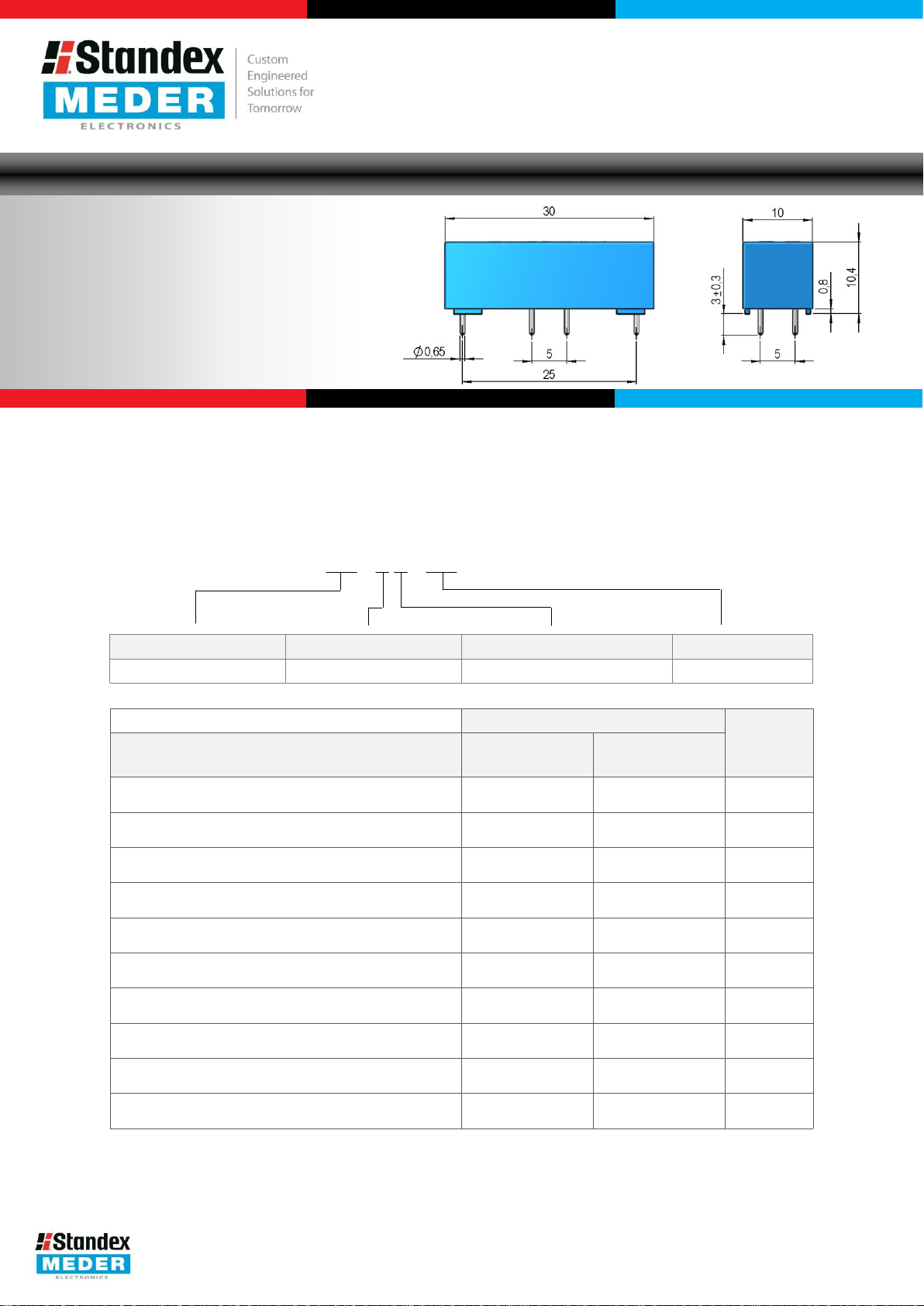
Description: LI 00- 1 A XX
Nominal Voltage Contact QTY Contact Form Switch Model
05, 12, 24 1 A 31, 85
Options
(max.)
DC combination of V&A not to exceed their individual max.’s
(max.)
peak AC
(max.)
or peak AC
(max.)
or peak AC
(max.)
0.5V & 50mA
(min.)
-5
Time (max.)
%, 100V Test Voltage
10kHz across open Switch
(Mercury)
Switch Model
31
85
Unit
(Dry)
50 100 W
500 1,000 V
2.0 1.0 A
2.0 2.5 A
80 150 mOhm
2.1
3 – 4.2 kVDC
1.2 1.1 ms
1.0 0.1 ms
X 1010 Ohm
0,3 0.5 pF
USA: +1.866.782.6339 │ [email protected]
Europe: +49.7731.8399.0 │ [email protected]
Asia: +86.21.37820625 │ [email protected]
Modifications in the sense of technical progress are reserved.
Version 01
27.01.2015
Page 2
LI Reed Relay
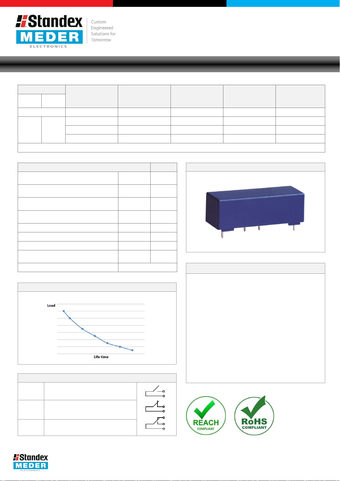
Life Test Data
*Load increase reduces life
A Global Leader in the Design, Development, and
Contact
Switch
The Pull
Relay
Dielectric Strength Coil/Contact (min.)
according to EN60255
Insulation Resistance Coil/Contact (typ.)
Rh<45
Capacitance Coil/Contact (typ.)
@ 10 kHz
Shock Resistance (max.)
1/2 sine wave duration 11ms
Vibration
Operating Temperature
Storage Temperature
Soldering
5 sec. max.
Washability
Handling
consideration, including a too high packing density.
Glossary
Form
NO = Normally Open Contacts
SPST = Single Pole Single
Form B
NC = Normally Closed
SPST
Form C
Changeover
SPDT = Single Pole Double
Manufacture of Sensor and Magnetic Components
Series Datasheet – LI Reed Relays
Coil Data
Form
1A 85
Model
Unit VDC Ohm VDC VDC mW
-In / Drop-Out Voltage and Coil Resistance will change at rate of 0.4% per °C.
Data Unit
%, 200V Test Voltage
Resistance (max.)
Temperature (max.)
Coil Voltage
-5
-35 to 95 °C
www.standexmeder.com
Coil Resistance
(nom.)
(typ.)
05 200 3.5 0.75 125
12 680 8.4 1.4 211
24 2,000 16.8 3.6 288
7 kVDC
1013 Ohm
1.2 pF
50 g
20 g
-20 to 70 °C
260 °C
Fully Sealed
Pull-In Voltage
(max.)
Drop-Out Voltage
(min.)
& Assembly Instructions
Nominal Coil
Power (typ.)
expectancy of Reed Switches
Contact Form
A
= Single Pole Single Throw
Contacts
Switching inductive and/or capacitive loads create
voltage and/or current peaks, which may damage
the relay. Protective circuits need to be used.
External magnetic fields needs to be taken into
This may influence the relays’ electrical
characteristics.
Mechanical shock impacts e.g. dropping the relays
may cause immediate or post-installation failure.
Wave soldering: maximum 260°/5 seconds.
Reflow soldering: Recommendations given by the
soldering paste manufacturer need to be
considered as well as the temperature limits of
other components/processes.
Throw
Throw
USA: +1.866.782.6339 │ [email protected]
Europe: +49.7731.8399.0 │ [email protected]
Asia: +86.21.37820625 │ [email protected]
Modifications in the sense of technical progress are reserved.
Version 01
27.01.2015
Page 3
A Global Leader in the Design, Development, and
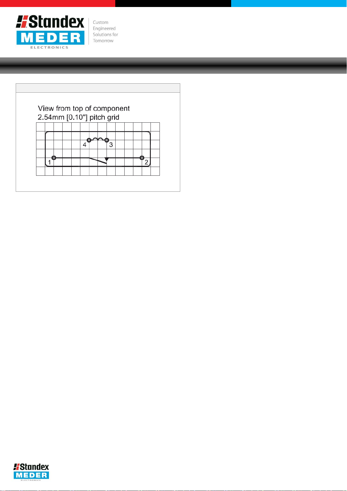
Pin Out
Manufacture of Sensor and Magnetic Components
Series Datasheet – LI Reed Relays
www.standexmeder.com
USA: +1.866.782.6339 │ [email protected]
Europe: +49.7731.8399.0 │ [email protected]
Asia: +86.21.37820625 │ [email protected]
Modifications in the sense of technical progress are reserved.
Version 01
27.01.2015
 Loading...