

Page 1
A Global Leader in the Design, Development, and
Part
Customer
Contact Data
Rated Power
Any
Switching Voltage
DC or
Switching Current
DC
Carry Current
DC
Contact Resistance
@
Breakdown
According
Operating
Incl. Bounce; Measured with w/ Nominal Voltage
Release Time (max.)
Measured
Insulation
Rh<45
Capacitance
@
Manufacture of Sensor and Magnetic Components
Series Datasheet – HE Reed Relays
www.standexmeder.com
HE Series
Reed Relays
Features: High Voltage Relay, Through-Hole / Axial Wire Option, Compact Design, Special Pin-Outs
Applications: High Voltage Test Sets, Cable Testers, Medical Equipment & Others
Markets: Medical, Test and Measurement & Others
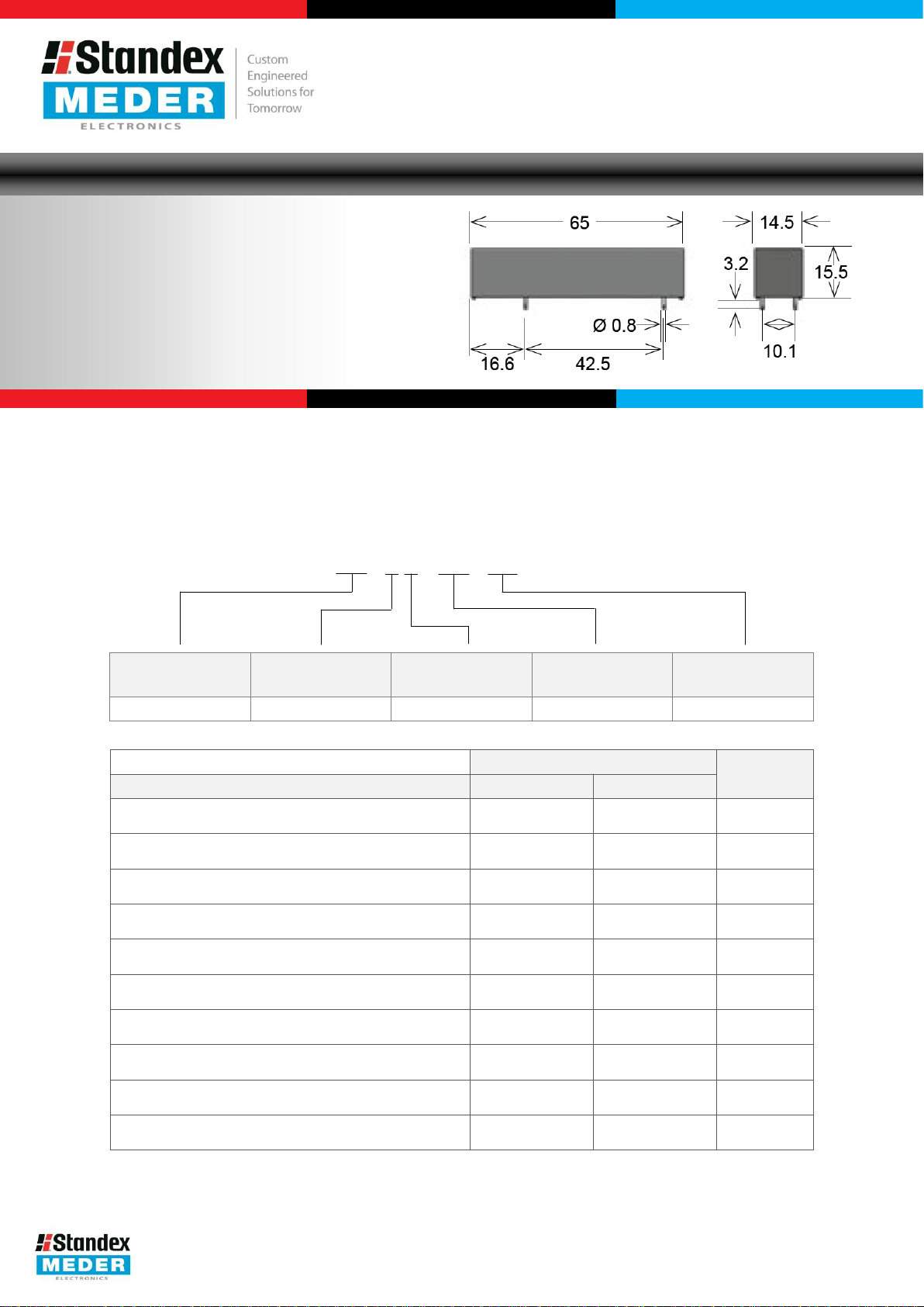
Description: HE 00- 0 X - 00- 00
Nominal Voltage
Contact QTY Contact Form Switch Model Pin Out
05, 06, 12, 24, 48 1, 2 A, B 69, 83 02, 03, 150, 300
Options
(max.)
DC combination of V&A not to exceed their individual max.’s
(max.)
peak AC
(max.)
or peak AC
(max.)
or peak AC
(max.)
0.5V & 50mA
Voltage (min.)
to EN60255-5
Time (max.)
with no Coil Excitation
Resistance (typ.)
%, 100V Test Voltage
(typ.)
10kHz across open Switch
Switch Model
69 83
Unit
50 50 W
10,000 7,500 V
3.0 3.0 A
5.0 5.0 A
150 150 mOhm
15 10 kVDC
3.0 3.0 ms
1.5 1.5 ms
10
12
10
12
Ohm
0.2 0.2 pF
USA: +1.866.782.6339 │ [email protected]
Europe: +49.7731.8399.0 │ [email protected]
Asia: +86.21.37820625 │ [email protected]
Modifications in the sense of technical progress are reserved.
Version 01
27.01.2015
Page 2
HE Reed Relay
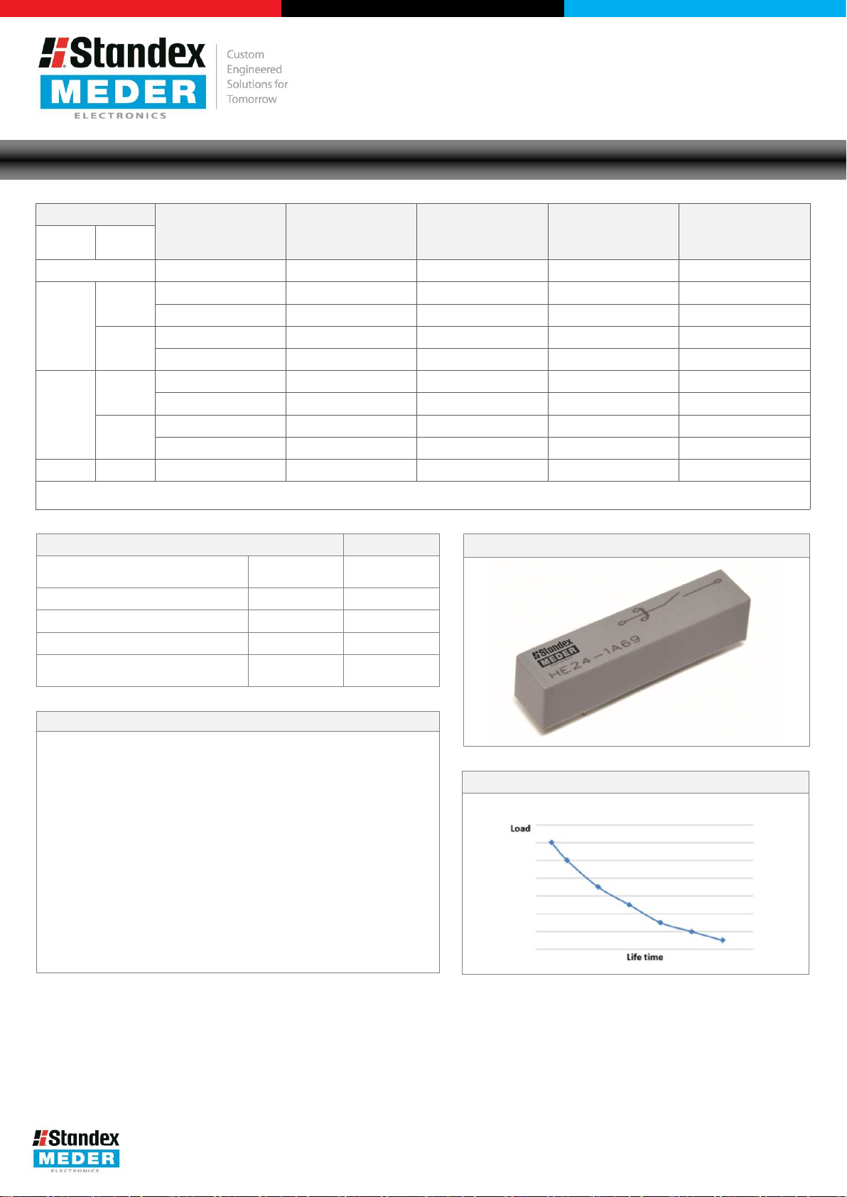
Life Test Data
*Load increase reduces life
A Global Leader in the Design, Development, and
Environmental
Shock Resistance (max.)
1/2 sine wave duration 11ms
Vibration
Operating Temperature
Storage Temperature
Soldering
5 sec. max.
Nominal Coil Power
Contact
Switch
The Pull
*
Handling
consideration, including a too high packing density. This may
Mechanical shock impacts e.g. dropping the relays may cause
Manufacture of Sensor and Magnetic Components
Series Datasheet – HE Reed Relays
Coil Data
Form
1A
1B*
2A 83 12 140 9 1 1,000
Re-closure of Form B may occur if the max. coil voltage is exceeded. Coil polarity on Form B must be observed. Pin 2 is positive.
Model
Unit VDC Ohm VDC VDC mW
69
83
69
83
-In / Drop-Out Voltage and Coil Resistance will change at rate of 0.4% per °C.
Data Unit
Resistance (max.)
Temperature (max.)
Coil Voltage
(nom.)
-35 to 105 °C
www.standexmeder.com
Coil Resistance
(typ.)
12 110 9 1 1,310
24 465 18 2 1,240
12 260 9 1 554
24 1050 18 2 554
12 260 9 1 554
24 1,050 18 2 548
12 410 9 1 351
24 1,520 18 2 378
50 g
20 g
-20 to 70 °C
260 °C
Pull-In Voltage
(max.)
Drop-Out Voltage
(min.)
(typ.)
& Assembly Instructions
Switching inductive and/or capacitive loads create voltage
and/or current peaks, which may damage the relay.
Protective circuits need to be used.
External magnetic fields needs to be taken into
influence the relays’ electrical characteristics.
immediate or post-installation failure.
Wave soldering: maximum 260°/5 seconds.
Reflow soldering: Recommendations given by the soldering
paste manufacturer need to be considered as well as the
temperature limits of other components/processes.
USA: +1.866.782.6339 │ [email protected]
Europe: +49.7731.8399.0 │ [email protected]
Asia: +86.21.37820625 │ [email protected]
Modifications in the sense of technical progress are reserved.
expectancy of Reed Switches
Version 01
27.01.2015
Page 3
A Global Leader in the Design, Development, and
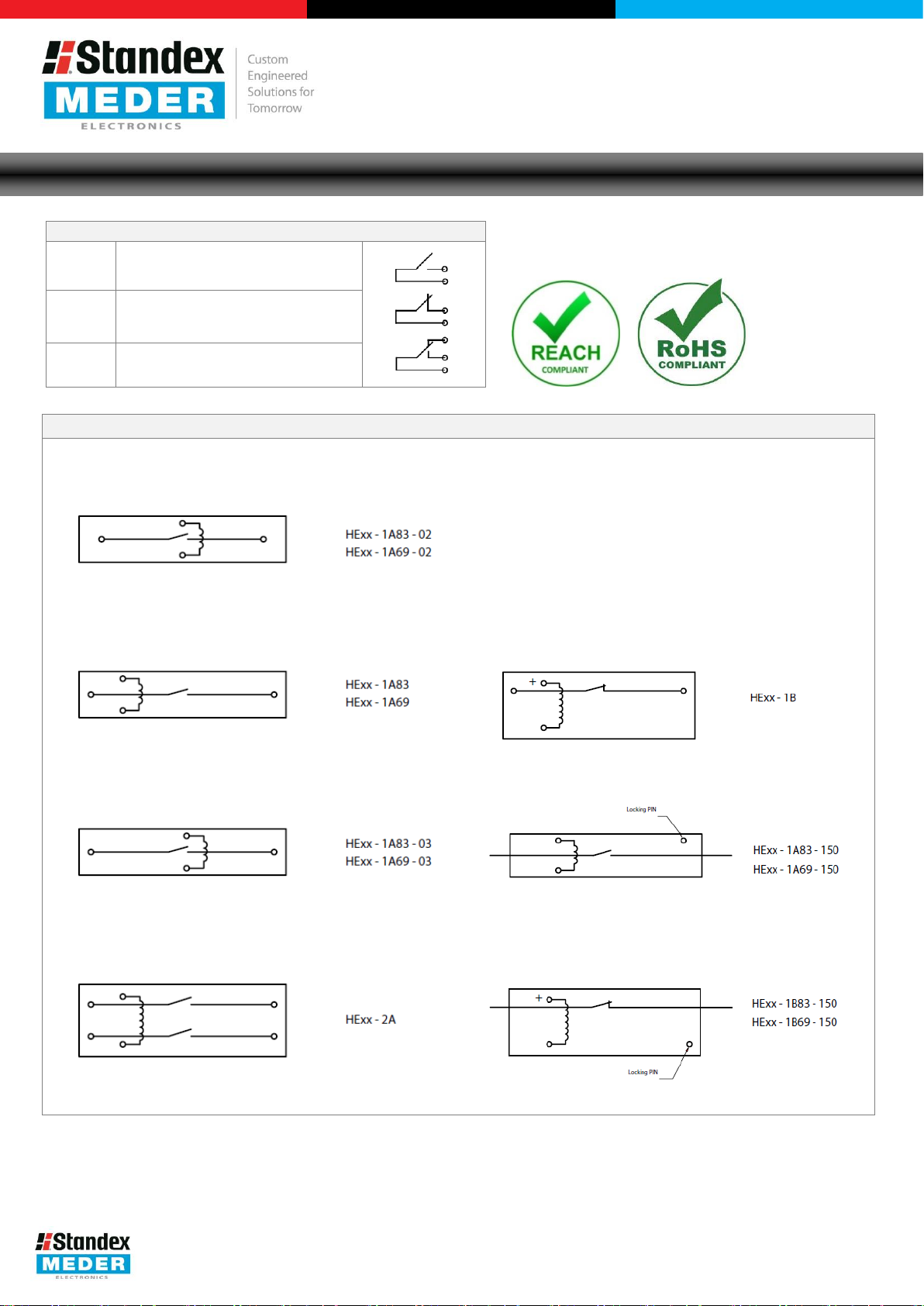
Pin Outs
Glossary Contact Form
Form
NO = Normally Open Contacts
SPST = Single Pole Single
Form B
NC = Normally Closed
SPST
Form C
Changeover
SPDT = Single Pole Double
Manufacture of Sensor and Magnetic Components
Series Datasheet – HE Reed Relays
A
= Single Pole Single Throw
Dimensions available in Product Datasheets.
Throw
Contacts
Throw
www.standexmeder.com
USA: +1.866.782.6339 │ [email protected]
Europe: +49.7731.8399.0 │ [email protected]
Asia: +86.21.37820625 │ [email protected]
Modifications in the sense of technical progress are reserved.
Version 01
27.01.2015
 Loading...