

Page 1
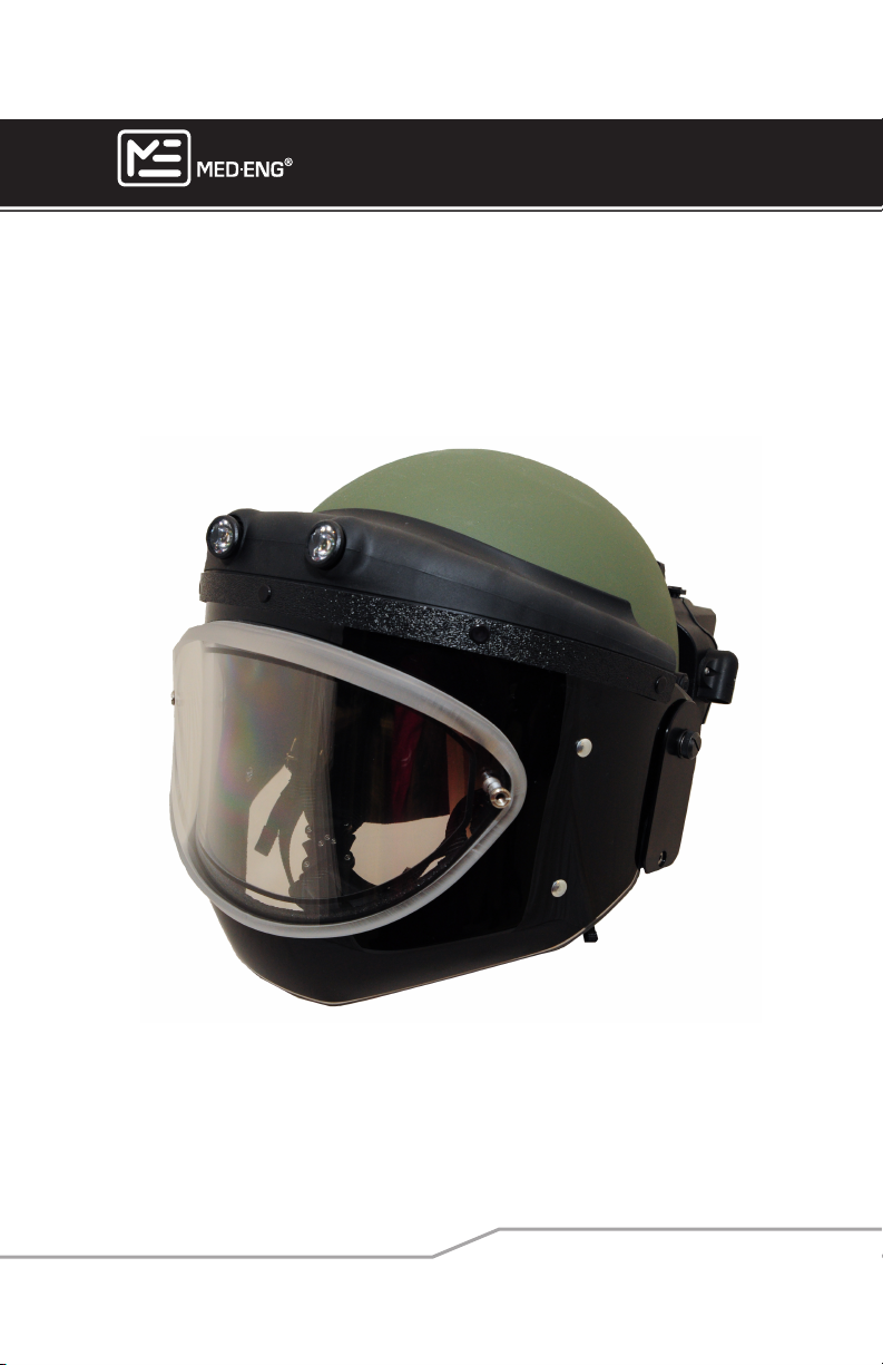
EOD® 9/9A HELMET
USER MANUAL
105-233 Rev J
Page 2

Page 3

EOD® 9/9A HELMET
USER MANUAL
Med-Eng is committed to continuous product improvement and, thus, reserves the right, in
its sole discretion, to make changes to products without prior notice. Accordingly, products,
including specications and appearance, are subject to change without notice and may
differ from the illustrative depictions. The information contained in this User Manual takes
precedence over any other prior document with regards to the current product description
and performance.
This document and its contents are the property of Med-Eng. Do not forward or disclose
this document in whole or in part to any other party without the written consent of Med-Eng.
Copyright © 2014 Med-Eng Holdings ULC. All rights reserved.
MED-ENG, ME Box Design, and EOD are Registered Trademarks of THE SAFARILAND
GROUP.
Page i
©2013 Med-Eng Holdings ULC. Company Proprietary and Condential
105-233 Rev J
Page 4

Page 5

EOD® 9/9A HELMET
USER MANUAL
CONTENTS
WARNINGS & CAUTIONS ������������������������������������������������������������������������1
FRAGMENTATION RESISTANCE �������������������������������������������������������������2
V50 BACKGROUND ����������������������������������������������������������������������������������� 3
EOD® 9/9A HELMET COMPONENTS �������������������������������������������������������� 4
PREPARING THE HELMET FOR OPERATIONS ���������������������������������������� 8
SIZING THE HELMET ��������������������������������������������������������������������������������8
REMOVING THE EAR PADS ���������������������������������������������������������������������� 9
REMOVING SPEAKERS FROM EARPADS ������������������������������������������������ 9
CHANGING THE COMFORT LINER SYSTEM ����������������������������������������� 10
INSTALLING THE VISOR ANTI-FOG/ANTI-SCRATCH APPLIQUÉS �������12
INSTALLING THE DEMISTER ������������������������������������������������������������������13
RAISING & LOWERING THE VISOR ��������������������������������������������������������14
CHANGING THE VISOR ��������������������������������������������������������������������������15
USING THE BREATHING APPARATUS (BA) CONFIGURATION ������������17
INSTALLING BATTERIES IN THE ONBOARD POWER SUPPLY (OPS) �� 18
CONNECTING THE SHIELDED POWER SUPPLY (SPS) AS A POWER
SOURCE ��������������������������������������������������������������������������������������������������20
INSTALLING BATTERIES IN THE SHIELDED POWER SUPPLY (SPS) ��21
ROUTING THE PATCHCORD AND REMOTE CONTROL CABLES ��������22
INSTALLING THE VISOR COVER ������������������������������������������������������������24
INSTALLING THE STEEL VISOR (OPTIONAL COMPONENT) ����������������24
INSTALLING DUST CAPS ������������������������������������������������������������������������25
OPERATION ���������������������������������������������������������������������������������������������26
PUTTING THE HELMET ON ��������������������������������������������������������������������26
CONNECTING THE CABLES TO THE HELMET �������������������������������������27
TAKING THE HELMET OFF THE HEAD ��������������������������������������������������28
USING THE REMOTE CONTROLLER �����������������������������������������������������29
TURNING ON THE HELMET VIA THE REMOTE ������������������������������������� 29
OPERATING THE SPEAKERS �����������������������������������������������������������������30
OPERATING THE VENTILATION FANS ���������������������������������������������������31
Page ii
©2013 Med-Eng Holdings ULC. Company Proprietary and Condential
105-233 Rev J
Page 6

USER MANUAL
OPERATING THE SEARCHLIGHTS���������������������������������������������������������32
OPERATING THE VISOR DEMISTER (OPTIONAL) ���������������������������������33
HELMET-REMOTE COMMUNICATIONS INDICATOR �����������������������������34
MONITORING BATTERY LIFE �����������������������������������������������������������������34
SUGGESTED OPERATING/STORAGE CONDITIONS ����������������������������35
TROUBLESHOOTING GUIDE ������������������������������������������������������������������ 36
SUGGESTED PACKING PROCEDURE ���������������������������������������������������37
CARE AND MAINTENANCE ��������������������������������������������������������������������38
PREVENTIVE MAINTENANCE ����������������������������������������������������������������� 38
CLEANING THE SPS AND REMOTE CONTROL ������������������������������������39
CLEANING THE VISOR ���������������������������������������������������������������������������39
CLEANING THE HELMET SHELL ������������������������������������������������������������ 39
CLEANING THE WASHABLE ITEMS �������������������������������������������������������39
CLEANING AND REPLACING FILTERS ���������������������������������������������������40
REPLACING SHOCK ABSORBING VISOR PIVOTS �������������������������������� 40
Page iii
©2013 Med-Eng Holdings ULC. Company Proprietary and Condential
105-233 Rev J
Page 7

EOD® 9/9A HELMET
EOD® 9/9A HELMET
USER MANUAL
WARNINGS & CAUTIONS
WARNING AND LIMITATION OF LIABILITY
THIS PRODUCT SHALL NOT BE USED BEFORE CAREFULLY READING ALL PRECAUTIONS, DIRECTIONS
FOR USE, CARE AND SIZING INSTRUCTIONS, LIMITED WARRANTY AND LIMITATIONS OF LIABILITY.
DO NOT USE THIS PRODUCT IF IT IS DAMAGED OR IF THERE ARE OTHER SIGNS OF WEAR AND TEAR.
EXPLOSIVE ORDNANCE DISPOSAL IS A HIGH RISK ACTIVITY AND SHOULD ONLY BE PERFORMED BY
HIGHLY TRAINED PROFESSIONALS. THIS PRODUCT IS USED SOLELY AT THE RISK AND LIABILITY OF
THE PERSON(S) WHO WEARS IT. USE OF THIS PRODUCT DOES NOT GUARANTEE PROTECTION FROM
INJURY, DEATH, DISMEMBERMENT AND/OR DISABILITY AND WILL NOT ELIMINATE DAMAGE TO, OR THE
DESTRUCTION OF PROPERTY.
PERSONNEL SHALL NOT USE THIS PRODUCT UNTIL THEY ARE FULLY TRAINED AND AWARE OF THE OPERATIONAL CHARACTERISTICS OF THIS PRODUCT. CONTINUED USE OF THIS PRODUCT WITH FAILURE
TO FOLLOW INSTRUCTIONS FOR USE AND CARE MAY ALSO CONTRIBUTE TO THE CAUSE OF INJURY,
DEATH, DISMEMBERMENT AND/OR DISABILITY, AND MAY CONTRIBUTE TO THE CAUSE OF DAMAGE TO,
AND/OR THE DESTRUCTION OF PROPERTY.
UNDER NO CIRCUMSTANCES SHALL MED-ENG, NOR ANY OF ITS AFFILIATES, DIRECTORS, OFFICERS,
EMPLOYEES AND/OR CONTRACTORS BE LIABLE FOR ANY BODILY INJURY TO PERSONNEL, INCLUDING DEATH, DISMEMBERMENT AND/OR DISABILITY; NOR FOR DAMAGE TO OR THE DESTRUCTION OF
PROPERTY; NOR ANY OTHER REPERCUSSION STEMMING FROM THE USE OF THE PRODUCT WITHIN ITS
INTENDED ENVIRONMENT. MED-ENG, AND ALL ITS AFFILIATES, DIRECTORS, OFFICERS, EMPLOYEES
AND/OR CONTRACTORS SHALL NOT BE LIABLE FOR, AND ANY AND ALL CLAIMS AGAINST MED-ENG
ARE WAIVED FOR, SPECIAL, INDIRECT, INCIDENTAL, OR CONSEQUENTIAL DAMAGES OR EXPENSE OF
ANY NATURE, INCLUDING, BUT NOT LIMITED TO INJURY, DEATH, DISMEMBERMENT, DISABILITY, LOSS OF
PROFITS OR INCOME.
MED-ENG OFFERS THIS PRODUCT, AND THE BUYER AND USER ACCEPT IT, SUBJECT TO MED-ENG STANDARD CONDITIONS OF SALE, AND THE LIMITATION OF WARRANTY, LIABILITY AND REMEDIES PROVIDED
THEREIN, INCLUDING BUT NOT LIMITED TO THIS PRODUCT AND WARNING LABEL.
BATTERY CAUTION
PERFORM VISUAL INSPECTION WHEN REMOVING BATTERIES POST-USE. SHOULD THE CASING BE DAM-
AGED, SWOLLEN, OR LEAKING; LOW LEVELS OF IRRITATING VAPOURS MAY HAVE BEEN RELEASED. USER
SHOULD BE NOTIFIED AND SEEK MEDICAL ATTENTION IF CONCERNED, ESPECIALLY WHERE PRE-EXISTING
HEALTH CONDITIONS MY BE AGGRAVATED.
For EOD® 9A Helmet Users
The EOD® 9A Helmet is designed to serve those EOD mission areas where harsh electro-magnetic environments, such
as those common with active electronic counter measures (ECM) are encountered. EOD employed ECM systems can
cause interference with helmet function as well as inuence electronics external to the helmet such as wireless communications. The EOD® 9A Helmet has been designed to mitigate this inuence and risk of helmet function loss when powered by the onboard power supply. The EOD® 9A Helmet is Def Stan 59-41, EMC Class A and MIL-STD-461F compliant.
NOTE: Further information on Med-Eng’s specication for this product can be found in PS0137 - Med-Eng® EOD® 9/9A
Helmet Product Specication.
0120
The Med-Eng® EOD® 9 and 9A Helmets have been subject to EC type examination for Directive 89/686/EEC (PPE Direc-
tive) by: Notied Body No. 0120:
SGS United Kingdom Ltd.,
Unit 202b Worle Parkway,
Weston-super-Mare,
BS22 6WA, UK
*applicable to Canadian manufactured product only.
Page 1
*
©2013 Med-Eng Holdings ULC. Company Proprietary and Condential
105-233 Rev J
Page 8
EOD® 9/9A HELMET
USER MANUAL
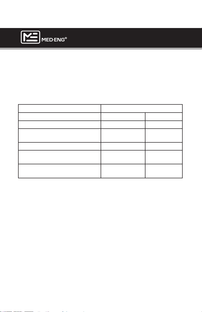
FRAGMENTATION RESISTANCE
The fragmentation resistance of the various components of the EOD®
9/9A Helmet, in terms of V50 levels obtained, according to the
MIL-STD-662F Test Specication, using the 1.1gram 17 grain chisel
nose FSP fragment simulator, meets or exceeds the following:
Component V50 Rating
Meters/second Feet/second
Helmet 600 1968
EOD Visor Periphery
(opaque area)
EOD Visor Viewing Area 780 2558
EOD Visor Viewing Area with
Steel Add-On (optional)
BA Visor (Average of opaque
and visible regions)
700 2296
1130 3706
700 2296
Page 2
©2013 Med-Eng Holdings ULC. Company Proprietary and Condential
105-233 Rev J
Page 9

EOD® 9/9A HELMET
USER MANUAL
V50 BACKGROUND
V50 testing is a statistical tool used for evaluating the penetration re-
sistance of materials involved in ballistic armour to specic laboratory
fragment simulators. The V50 test is used extensively in ballistic material
design, in tandem with product development. Under some conditions,
it may also be used to compare relative performance of fragmentation
resistant materials or armour, so long as the materials are identical in basic construction, e.g., comparing aramid soft body armour. The V50 limit
cannot be used to compare dissimilar armour constructions, e.g., soft
versus rigid materials. Care must be taken when interpreting V50 ratings due to the fact that the probability of an explosive device fragment
having the exact same physical properties as the simulated fragment
used during testing is essentially non-existent. There exist a number of
different fragment simulators, both in terms of shape and size, thus it is
necessary to stipulate the precise simulator that is being used to arrive
at a V50 value for objective comparisons. Although standardized test
methods exist for V50 determination, there still exist subtle variations in
carrying out the actual test between different laboratories/manufacturers,
which may lead to small variations in the V50 results.
Page 3
©2013 Med-Eng Holdings ULC. Company Proprietary and Condential
105-233 Rev J
Page 10
EOD® 9/9A HELMET
USER MANUAL
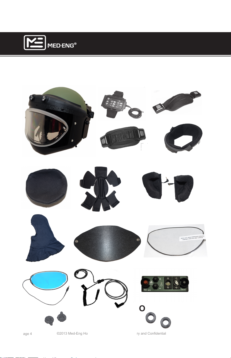
EOD® 9/9A HELMET COMPONENTS
Standard Conguration Seatbelt Type Buckle
A
D
C
B
B
E
K
Page 4
N
F
H
I
J
L
O
©2013 Med-Eng Holdings ULC. Company Proprietary and Condential
G
M
105-233 Rev J
Page 11
EOD® 9/9A HELMET
USER MANUAL
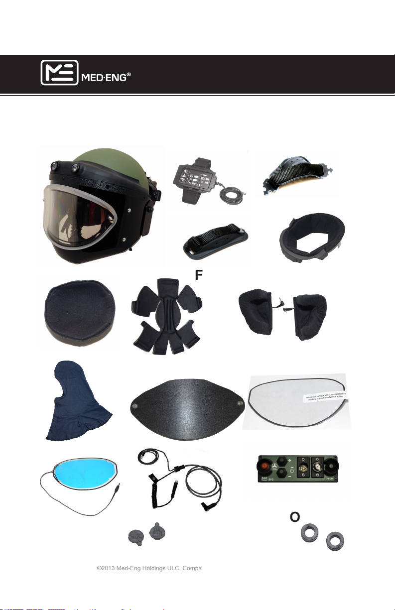
Standard Conguration Side Release Buckle
A
D
C
B
K
E
H
N
F
L
G
I
J
M
O
Page 5
©2013 Med-Eng Holdings ULC. Company Proprietary and Condential
105-233 Rev J
Page 12

EOD® 9/9A HELMET
USER MANUAL
Standard EOD® 9/9A Helmet System Components
A - Remote Control Module
B - Large Size Chin Strap - to be used for medium & large head sizes
only
C - Small Size Chin Strap - to be used for small head sizes only
D - Comfort Liner
E - Crown Pad
F - Sizing Pads (Thick, Medium & Thin)
G - Ear Pads with speakers
H - Balaclavas (3)
I - Visor Cover
J - Anti-Scratch/Anti-Fog Visor Appliqué
K - EOD® Visor Demister
L - Universal Patchcord
M - Shielded Power Supply (SPS)
N - Searchlight & Visor Demister Dust Caps
O - Replacement Visor Shock Absorbing Pivots (2)
Eight C-Cell Alkaline Batteries (not shown)
Soft Carry Bag (not shown)
User Manual & Video (not shown)
Set of 8 AA Alkaline Batteries (not shown)
EOD® 9/9A Helmet Features
• 4-Point Retention System
• Air Ventilation System
• Microphone & Speakers
• Environmental Awareness System (EAS)
• Onboard Power Supply (OPS)
• EOD® Visor with Wiper & Built-In LED Searchlights
Page 6
©2013 Med-Eng Holdings ULC. Company Proprietary and Condential
105-233 Rev J
Page 13
EOD® 9/9A HELMET
USER MANUAL
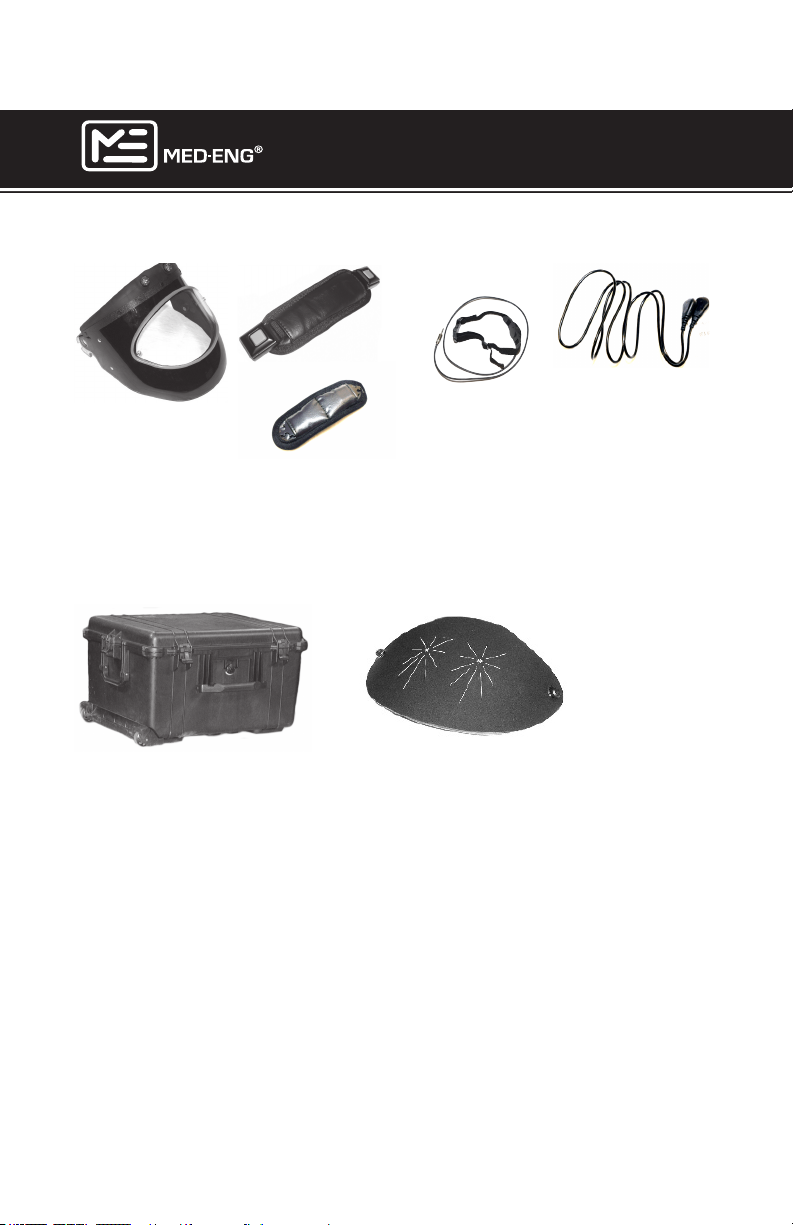
Breathing Apparatus (BA) Capabilities Kit
Seatbelt
Type Buckle
Siderelease
Buckle
BA Visor, BA Visor Cover (not shown), Neck Straps, Throat Microphone, Anti-Scratch/Anti-Fog BA Visor Appliqués (qty 5) (not shown),
Grounding Strap, 44” Grounding Strap
Optional Components
Hard Carry Case, EOD Visor Steel Add-On, Rechargeable (NiMH) AA
Batteries and Charger Kit (not shown), Rechargeable (NiMH) C-Cell
Batteries and Charger Kit (not shown), BA Visor Demister (not shown),
BA Visor Appliqués ((50 per pack (not shown)).
Accessories
EOD Camcorder Visor, BA Camcorder Visor, Automatic Speech
Recognition (ASR), EOD Live Video (LV)
Page 7
©2013 Med-Eng Holdings ULC. Company Proprietary and Condential
105-233 Rev J
Page 14
EOD® 9/9A HELMET
USER MANUAL
PREPARING THE HELMET FOR OPERATIONS
SIZING THE HELMET
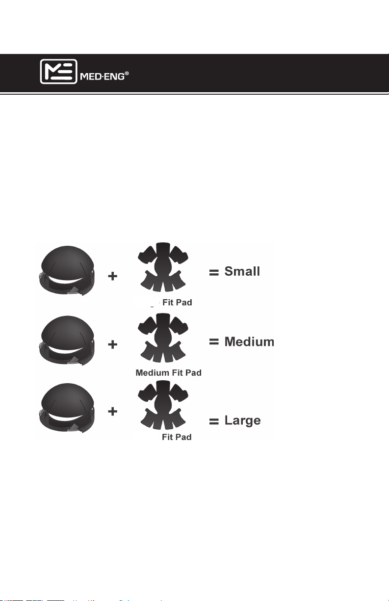
The EOD® 9/9A Helmet is designed to t head sizes between 50 cm and
65 cm (19.7” to 25.6”) circumference. Each EOD® 9/9A Helmet is supplied with 1 comfort liner, 1 crown pad and 3 sizing pads: small, medium
and large. The small sizing pad is 1/2” thick, the medium sizing pad is
1/4” thick and the large sizing pad is 3/16” thick. Sizing pads are individually removable and interchangeable to allow for extensive customization
of t.
Head Size
50 cm to 55 cm
19.7” to 21.7”
Thick
55 cm to 60 cm
21.7” to 23.6”
60 cm to 65 cm
23.6” to 25.6”
Thin
IMPORTANT:
Any combination of sizing pads can be used to further customize
the t of the EOD® 9/9A Helmet. Remember, the EOD® 9/9A Helmet
has been designed to accommodate head sizes from 5th percentile
female to 95th percentile male. Take the time to properly congure
your comfort liner to suit you.
Page 8
©2013 Med-Eng Holdings ULC. Company Proprietary and Condential
105-233 Rev J
Page 15
REMOVING THE EAR PADS
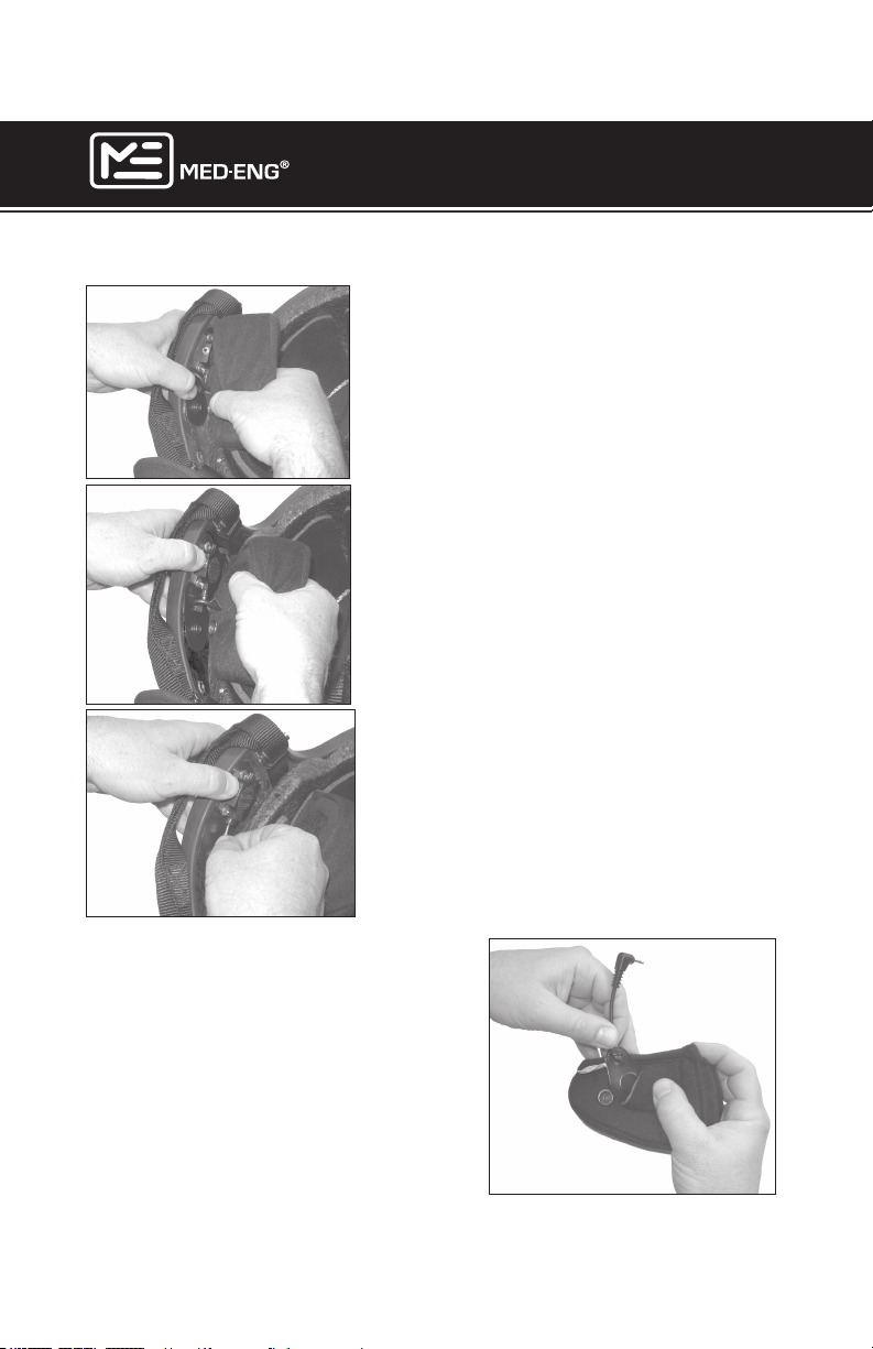
1. Hold down plastic tab and place
thumb close to earpad snap. Pull to
remove.
2. Detach VELCRO® as shown.
EOD® 9/9A HELMET
USER MANUAL
3. Unplug speaker jack from interconnect
housing.
REMOVING SPEAKERS FROM
EARPADS
To remove speakers, hold the base of
speaker jack cord as shown and pull
gently.
Page 9
©2013 Med-Eng Holdings ULC. Company Proprietary and Condential
105-233 Rev J
Page 16
EOD® 9/9A HELMET
USER MANUAL
CHANGING THE COMFORT LINER SYSTEM
The EOD® 9/9A Helmet is pre-congured with a medium sizing pad.
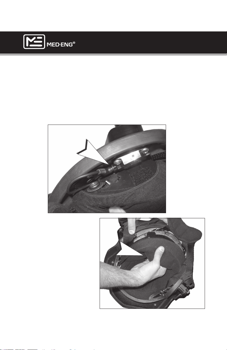
To remove a comfort liner:
Remove ear pads, as shown on page 9, and make sure that the
speakers are detached from the speaker jacks (A).
A
Pull up from bottom to remove
the comfort liner (B). Remove
the crown and the sizing
pad(s).
Page 10
©2013 Med-Eng Holdings ULC. Company Proprietary and Condential
B
105-233 Rev J
Page 17
EOD® 9/9A HELMET
USER MANUAL
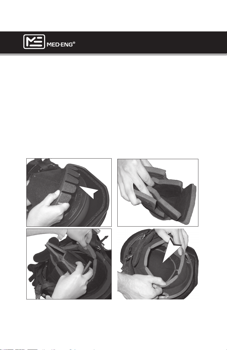
To replace a comfort liner:
1. Attach the comfort liner using plastic tabs (C) that wedge in between the impact liner and the helmet shell. Orient the comfort liner so
the side with 7 tabs (C) faces the front of the helmet and the side with 4
tabs faces the back. Wedge the tabs in between the helmet shell and the
impact liner.
2. After the comfort liner is installed, fold the desired sizing pad(s) as
shown (D) and place into helmet (E). Align the pad with the VELCRO
®
patches on the sides and bottom of impact liner.
3. Place the crown pad (F) on top of the sizing pad and fold the com-
fort liner into helmet.
C
D
F
E
Page 11
©2013 Med-Eng Holdings ULC. Company Proprietary and Condential
105-233 Rev J
Page 18
EOD® 9/9A HELMET
USER MANUAL
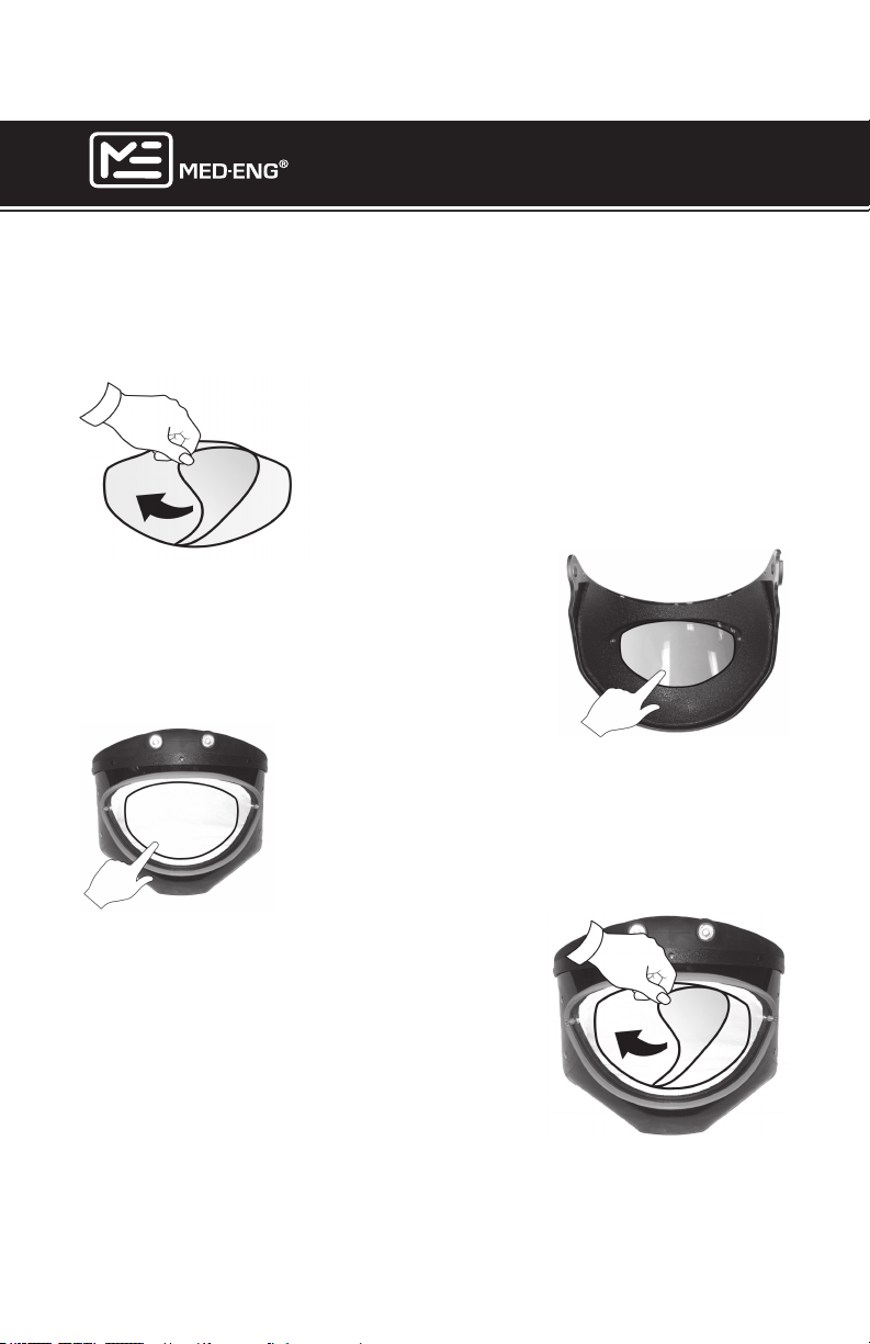
INSTALLING THE VISOR ANTI-FOG/ANTI-SCRATCH
APPLIQUÉS
Before you start: Ensure that the application surface of the visor is
clean and dust free.
NOTE: Visor is shipped from factory with
appliqué already installed.
1. Peel the backing to expose the adhesive
strip.
2. For Anti-Fog Protection: Center the appliqué on the inside of the visor viewing area.
3. Press all the way around to secure.
4. For Anti-Scratch Protection: Center the appliqué on the outside of the visor viewing area.
5. Press all the way around to secure.
6. Remember to peel the outer protective
layer from the appliqué.
7. Replace appliqués as required.
NOTE: When an appliqué is removed,
some adhesive residue may remain on the
visor. Use duct tape to remove this residue
before installing the replacement appliqué.
Page 12
©2013 Med-Eng Holdings ULC. Company Proprietary and Condential
105-233 Rev J
Page 19
EOD® 9/9A HELMET
USER MANUAL
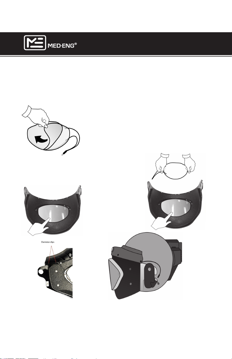
INSTALLING THE DEMISTER
Before you start: Ensure that the application surface of the visor is
clean and dust free.
NOTE: When an appliqué is removed,
some adhesive residue may remain on the
visor. Use duct tape to remove this residue
before installing the demister.
1. Peel the backing to expose the adhesive
strip.
2. Center the demister on the
inside of the visor viewing area.
4. Use the provided clips
(2) to attach the cable to
the visor wiper.
Page 13
©2013 Med-Eng Holdings ULC. Company Proprietary and Condential
3. Press all the
way around to
secure.
5. Plug the demister wire into the
jack on the left side of the helmet.
105-233 Rev J
Page 20
EOD® 9/9A HELMET
USER MANUAL
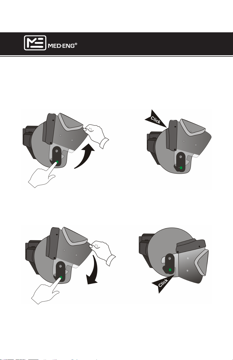
RAISING & LOWERING THE VISOR
To raise the visor: Push the green button on the right side of the helmet
and move the visor up until it clicks into place.
To lower the visor: Push the green button on the right side of the helmet
and move the visor down until it clicks into place.
Page 14
©2013 Med-Eng Holdings ULC. Company Proprietary and Condential
105-233 Rev J
Page 21
EOD® 9/9A HELMET
USER MANUAL
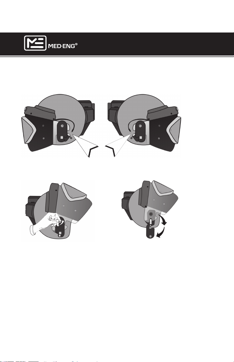
CHANGING THE VISOR
1. Unplug the searchlight and demister wires.
2. Always start with the visor in the “UP” position. (See previous
section.) Loosen the knobs to release the black plates.
Page 15
©2013 Med-Eng Holdings ULC. Company Proprietary and Condential
105-233 Rev J
Page 22
EOD® 9/9A HELMET
USER MANUAL
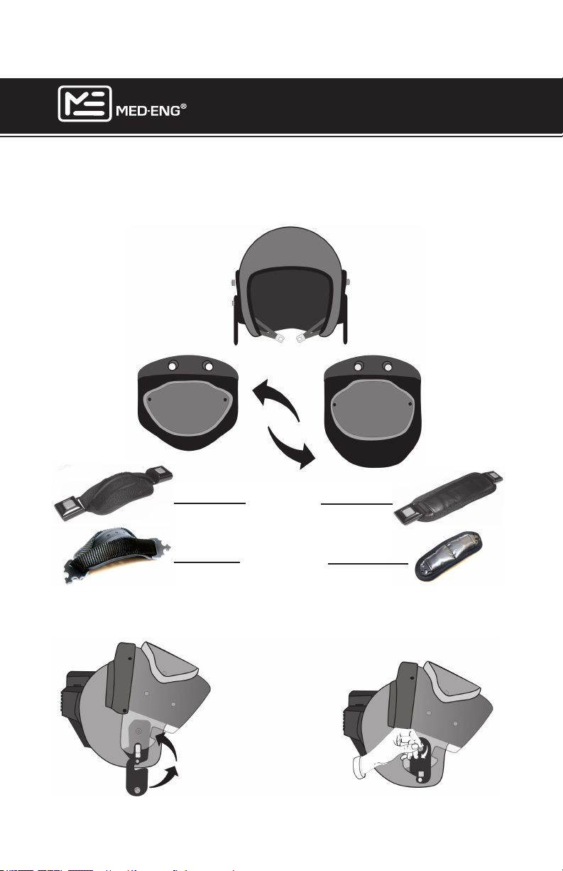
3. Select the appropriate strap. The chin strap (A) is recommended for
use with the EOD® visor. The neck strap (B) is recommended for use with
the BA visor. Both straps snap easily to the retention system via quick
release buckles.
Seatbelt Type Buckle
Side-Release Buckle
BA
4. Install the replacement visor (in the “UP” position). Carefully expand
the visor to ease it over the rubber pivots (C) on either side.
Position the black plates and tighten the knobs to secure.
C
Page 16
©2013 Med-Eng Holdings ULC. Company Proprietary and Condential
105-233 Rev J
Page 23
EOD® 9/9A HELMET
USER MANUAL
USING THE BREATHING APPARATUS (BA)
CONFIGURATION
SCBA masks vary in size and shape. The following masks are known to
t well with the EOD® 9/9A Helmet with BA visor installed:
• Dräger Panorama Nova
• MSA Ultra Elite
• Avon Protection Systems Viking SCBA
• Avon Protection Systems ST53 SCBA/APR/PAPR
• Scott-First Responder Respirator
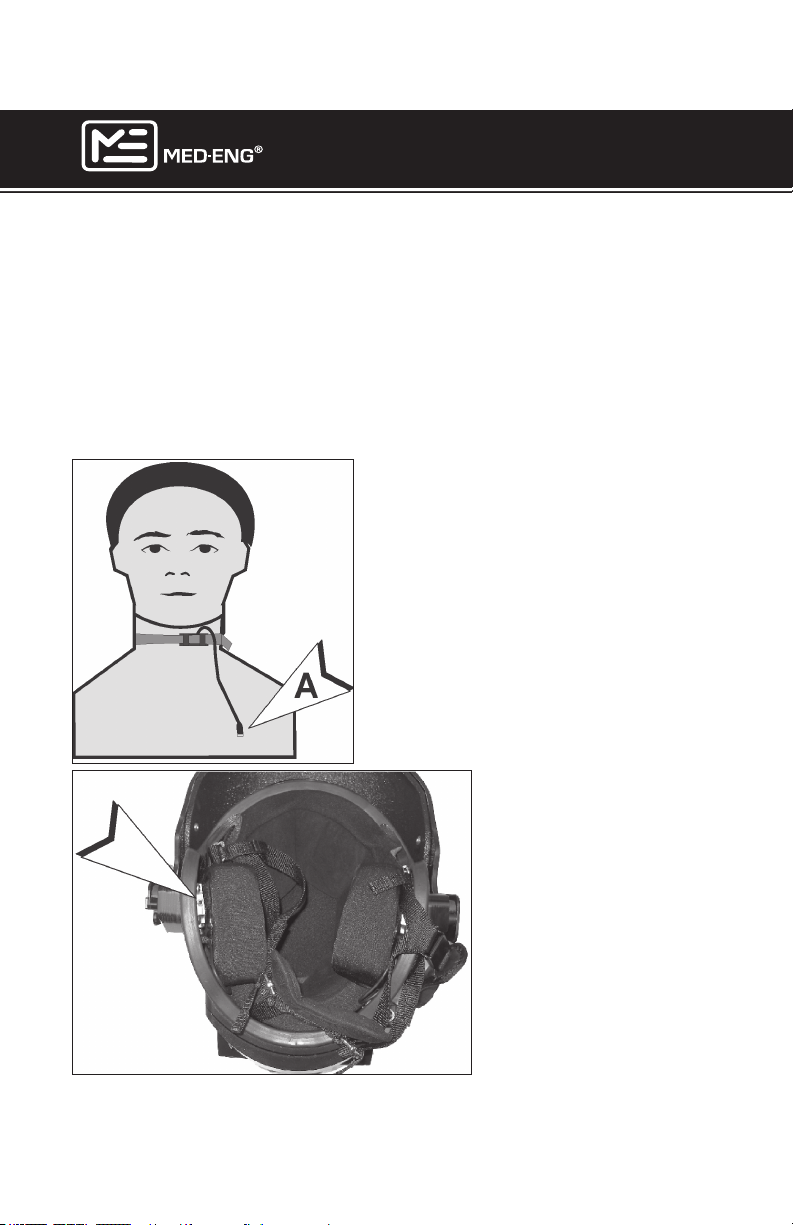
The throat microphone can be
worn over the cool suit hood or
standard balaclava. Position the
throat mic as shown.
Plug the microphone (A) into the
helmet via the jack (B) under the
right ear pad.
Page 17
B
©2013 Med-Eng Holdings ULC. Company Proprietary and Condential
105-233 Rev J
Page 24
EOD® 9/9A HELMET
USER MANUAL
INSTALLING BATTERIES IN THE ONBOARD POWER
SUPPLY (OPS)
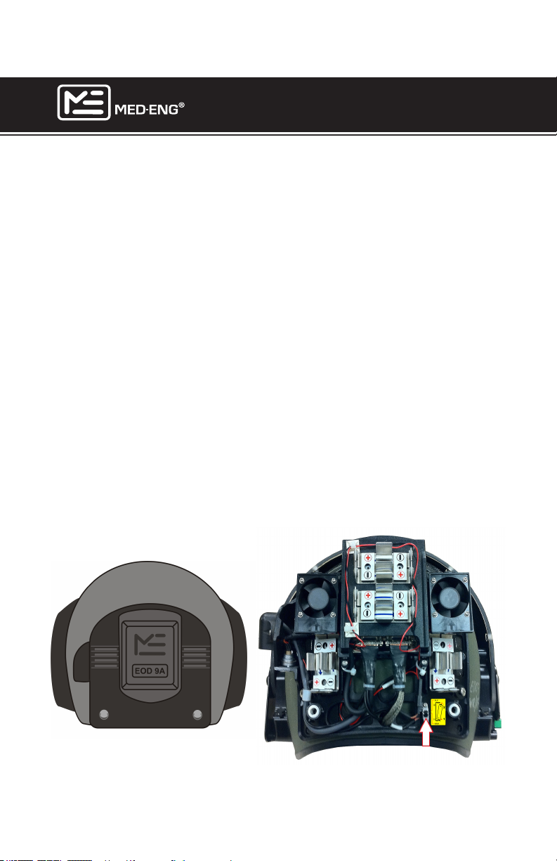
The EOD® 9/9A Helmet OPS is powered by 8 AA batteries.
A set of alkaline batteries will last up to 5 hours 20 minutes depending on
the load applied. A set of rechargeable Nickel Metal Hydride (NiMH) bat-
teries provide an operating time of up to 4 hours 20 minutes for the same
load.
Always make sure new alkaline batteries or fully recharged NiMH batteries
are installed before each mission. Always use good quality batteries (1400
mAh or better, Diameter: 0.57”, Length: 1.99”). Med-Eng does not recommend the use of Nickel Cadmium (NiCd) batteries as they do not have
adequate capacity. Operation time will vary according to which helmet
features are used. To open the back cover, pull on both fasteners (A), at
the same time and then lift the cover.
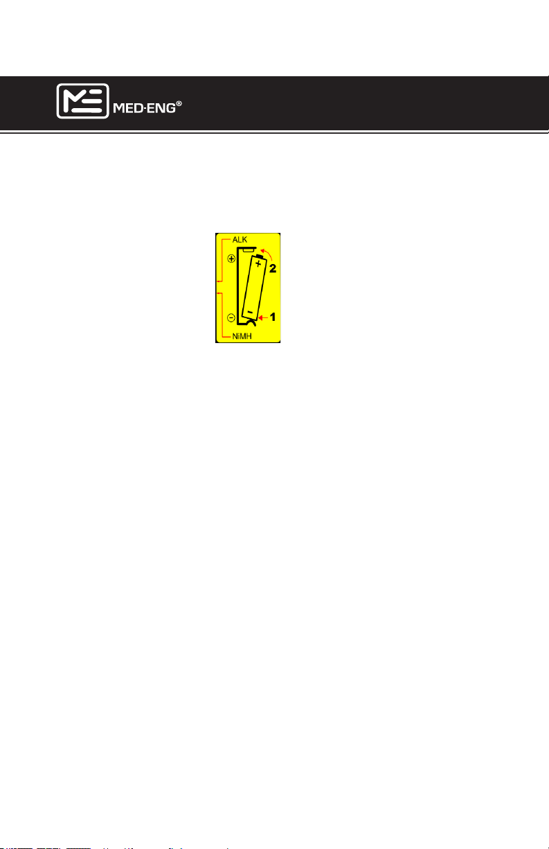
NOTE: The battery type switch (B) must be set for the type of batteries installed. If the switch is set incorrectly, the battery life indicator
on the remote will not provide an accurate reading.
IMPORTANT: If the SPS is used, battery types (alkaline or NiMH) used in
the SPS and OPS must match.
Where possible,
put the “-” end of
the battery in
rst
A A
B
Page 18
©2013 Med-Eng Holdings ULC. Company Proprietary and Condential
105-233 Rev J
Page 25
EOD® 9/9A HELMET
USER MANUAL
IMPORTANT: The batteries in the OPS (Onboard Power Supply) have
been designed to be inserted in one direction only according to polarity.
Install batteries referring to the yellow graphic beside the battery type
switch.
WARNING: Prior to inserting batteries into the OPS, a basic but deliberate inspection should be conducted. This inspection is meant to
detect the presence of corrosion and to conrm that there is no damage
to the outside covering of the batteries. If a battery covering is abraded,
ripped, torn or peeled away from the battery body or if any level of
corrosion is detected, the battery should not be placed into the OPS.
Damaged batteries should be disposed of in a safe manner.
WARNING: The OPS in the helmet should be inspected on a regular
basis for damage, loose battery holders, and the presence of battery
corrosion. If the battery holders are damaged or there is corrosion
present they should be replaced prior to the helmet being used. If a bat-
tery holder retention spring does not provide enough force to maintain
a battery in position, it may be adjusted by squeezing the retention
springs closer together and then releasing.
Page 19
©2013 Med-Eng Holdings ULC. Company Proprietary and Condential
105-233 Rev J
Page 26
EOD® 9/9A HELMET
USER MANUAL
CONNECTING THE SHIELDED POWER SUPPLY (SPS)
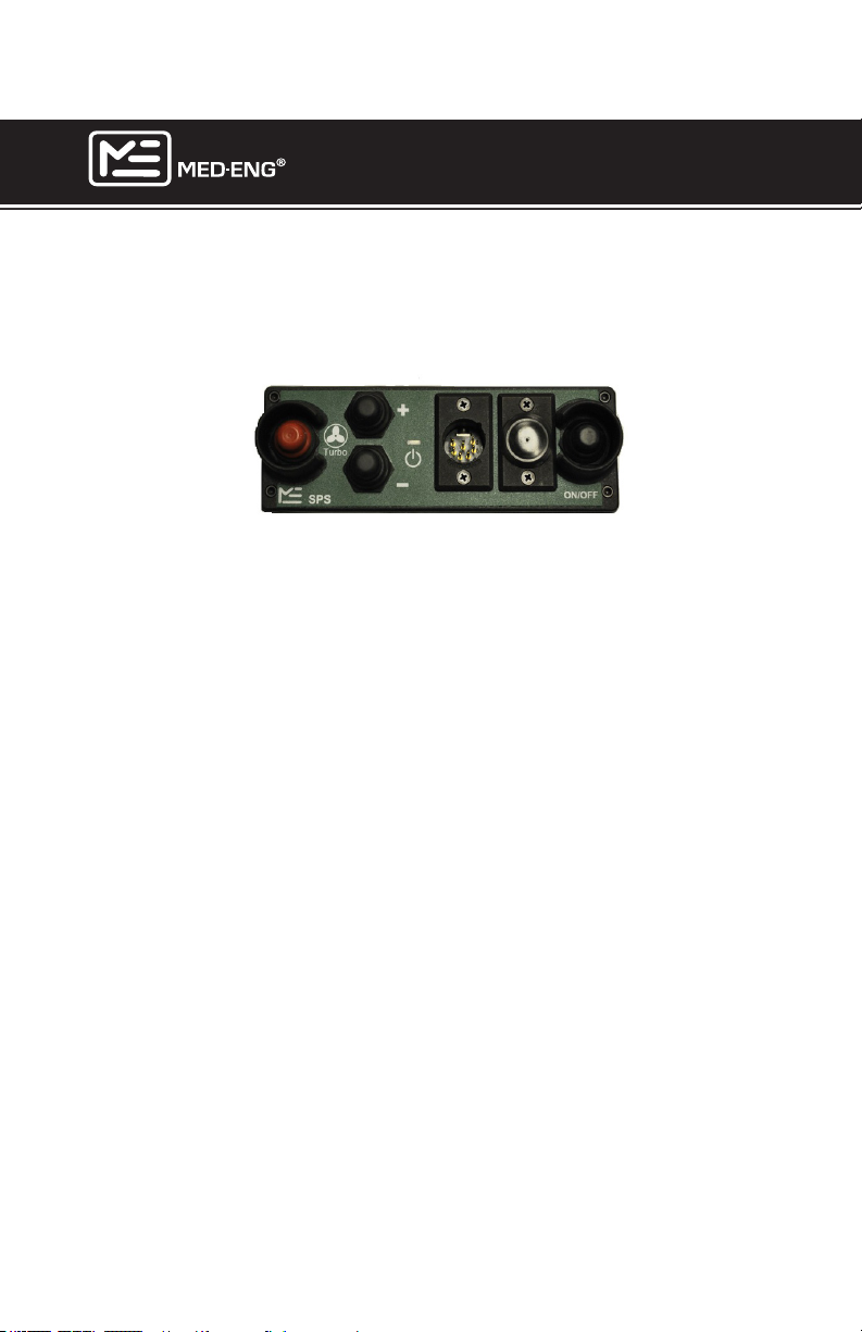
When the SPS is connected, power is automatically drawn from this
source rather than from the OPS. When the SPS has been drained,
power draw will automatically switch to the OPS. In combination with the
OPS, the SPS (with alkaline batteries) will increase operation time up to
8 hours and 50 minutes, depending on which helmet functions are used.
NOTE 1: The increase and decrease buttons will not work to control the
ventilation system. However, the red button can be used to initiate turbo
mode.
NOTE 2: The EOD® 9 Helmet may be connected to the Med-Eng legacy
IPS/APS. The EOD
®
9A helmet should only be used with the SPS to
reduce Electro Magnetic Interference (EMI) and mitigate impact of Electronic Countermeasures (ECM). The EOD® 9/9A Helmet is not designed
for operation with an EOD 7B Power Supply.
Page 20
©2013 Med-Eng Holdings ULC. Company Proprietary and Condential
105-233 Rev J
Page 27
EOD® 9/9A HELMET
USER MANUAL
INSTALLING BATTERIES IN THE SHIELDED POWER
SUPPLY (SPS)
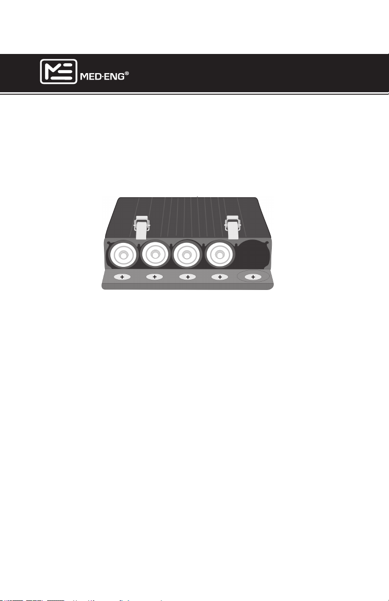
Use eight (8) Alkaline or ten (10) Rechargeable NiMH C cell batteries in
the SPS. Always install batteries so that the positive ends face toward
the door. When using alkaline batteries, position them as shown. The fth
tube should be lled only when rechargeable batteries are being used.
Med-Eng does not recommend the use of Nickel Cadmium (NiCd) batteries
as they do not hold adequate charge. Some military issued batteries do not
meet the minimum height requirement and must not be used in the SPS.
Many off-the-shelf batteries do not meet the minimum capacity requirement.
Always use good quality batteries that meet the following requirements:
Minimum Height 1.89” (4.80 cm)
Typical Diameter 1.0” (2.54 cm)
Minimum Alkaline Capacity 5 Ah
If batteries are not oriented correctly: The SPS will beep 3 times. If using
the OPS, the battery life light on the remote will illuminate yellow.
CAUTION: Do not use batteries that have cracked or missing heatshrink.
CAUTION: Use either ALL ALKALINE or ALL RECHARGEABLE NiMH
batteries in the SPS. Never mix battery types.
IMPORTANT: Battery types (alkaline or rechargeable NiMH) used in the
SPS and OPS must match.
Page 21
©2013 Med-Eng Holdings ULC. Company Proprietary and Condential
105-233 Rev J
Page 28
EOD® 9/9A HELMET
USER MANUAL
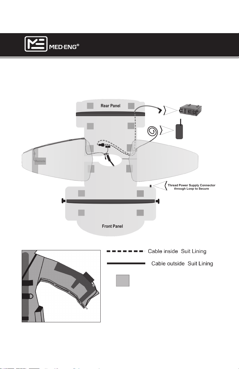
ROUTING THE PATCHCORD AND REMOTE CONTROL
CABLES
For Use with Wireless Radio
Page 22
VELCRO® Anchors
NOTE: The remote can be routed
through either sleeve depending on
user preference.
©2013 Med-Eng Holdings ULC. Company Proprietary and Condential
105-233 Rev J
Page 29
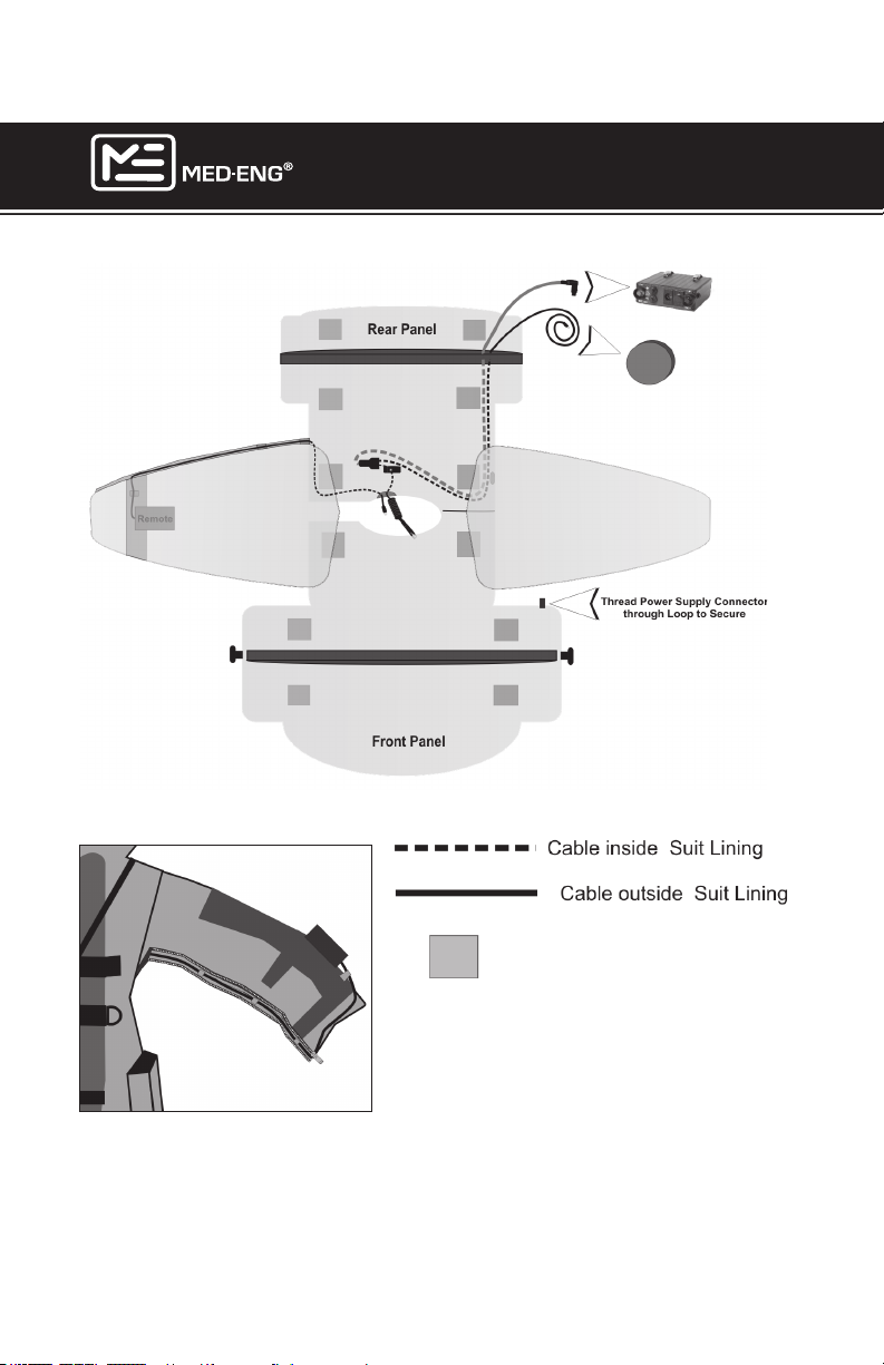
EOD® 9/9A HELMET
For Use with HW-300 Communications System
USER MANUAL
Page 23
VELCRO® Anchors
NOTE: The remote can be routed
through either sleeve depending on
user preference.
©2013 Med-Eng Holdings ULC. Company Proprietary and Condential
105-233 Rev J
Page 30
EOD® 9/9A HELMET
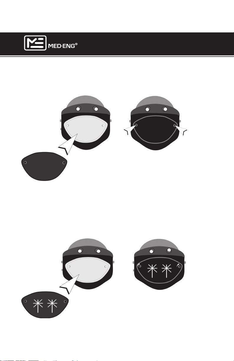
INSTALLING THE VISOR COVER
1. Position the Visor Cover over the viewing area.
2. Align and secure the fasteners.
INSTALLING THE STEEL VISOR (OPTIONAL
COMPONENT)
USER MANUAL
1. Position the Steel Visor over the viewing area.
2. Align and secure the fasteners.
NOTE: The Steel Visor can only be used with the EOD® Visor.
Page 24
©2013 Med-Eng Holdings ULC. Company Proprietary and Condential
105-233 Rev J
Page 31
EOD® 9/9A HELMET
USER MANUAL
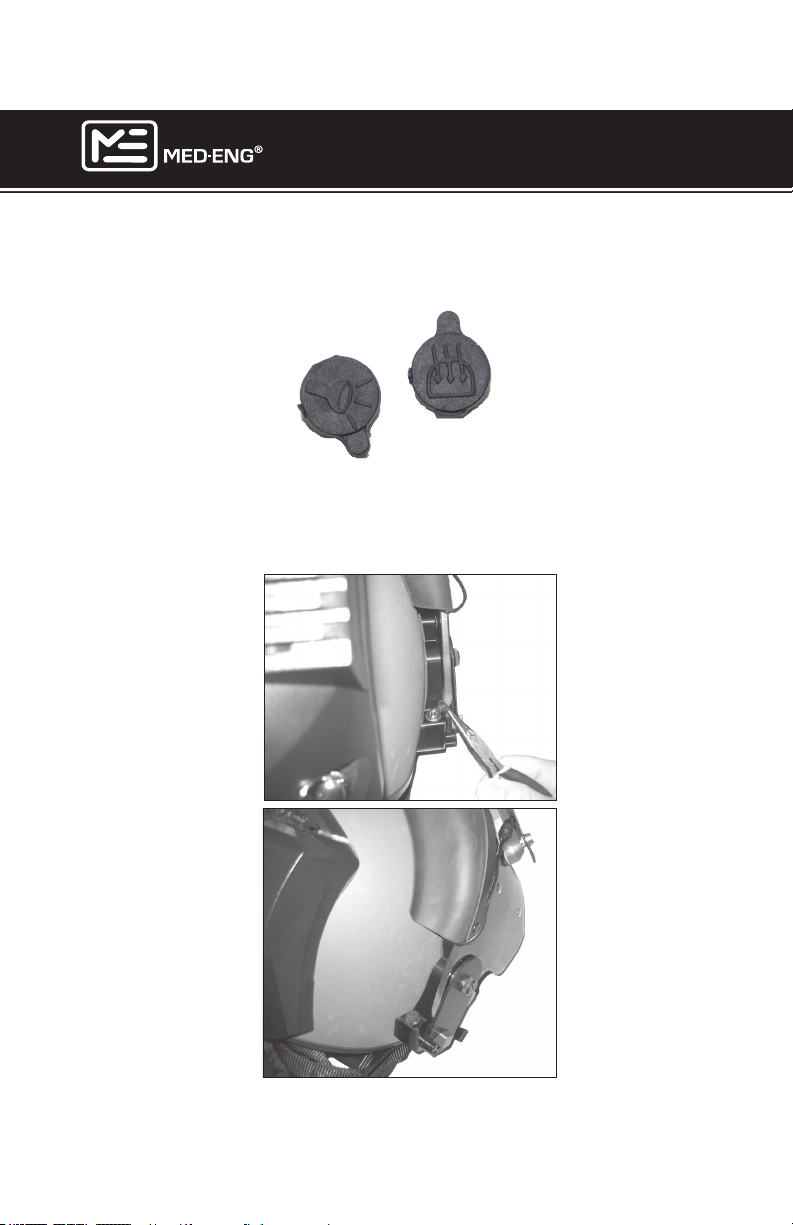
INSTALLING DUST CAPS
Below are the dust caps for the visor demister and search light jacks.
1. Push the dust cap into the jack as shown.
2. The visor demister dust cap goes onto the left side of the helmet.
3. The searchlight dust cap goes onto the right side of the helmet.
Page 25
©2013 Med-Eng Holdings ULC. Company Proprietary and Condential
105-233 Rev J
Page 32
OPERATION
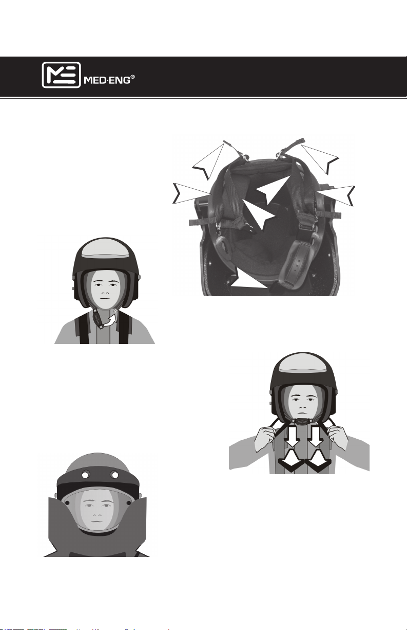
PUTTING THE HELMET ON
EOD® 9/9A HELMET
USER MANUAL
Pull on the short tabs (A)
and the inner side straps
(C), one set at a time to
loosen the retention system.
Make sure the chin strap (D)
is unfastened
With the visor raised and
locked in the upright position,
lift the helmet onto the head.
Fasten the chin strap.
Using the helmet shell rubber trim as a
guide, slide ngertips along the rubber
trim, and grab outer side strap (B) (the
outer side straps have double webbing).
Slide hands to the front and pull down
and forward to tighten. Note: Outer side
straps will remain outside of helmet
above shoulders when tightened.
A
B
D
C
C
1 1
2
A
B
2
Page 26
Put on the EOD Jacket. Lower the Visor.
Fasten the EOD Jacket collar (refer to the
EOD Suit manual). Make sure that the
technician can easily see the remote.
©2013 Med-Eng Holdings ULC. Company Proprietary and Condential
105-233 Rev J
Page 33
EOD® 9/9A HELMET
USER MANUAL
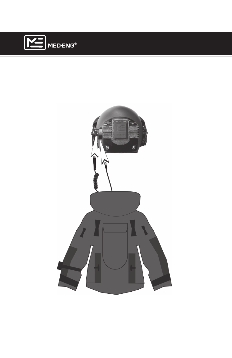
CONNECTING THE CABLES TO THE HELMET
Connect the Patchcord (A) and Remote Cable (B) to the rear of the Helmet as indicated below.
A
B
Page 27
©2013 Med-Eng Holdings ULC. Company Proprietary and Condential
105-233 Rev J
Page 34

EOD® 9/9A HELMET
USER MANUAL
REMOVING THE HELMET
NOTE: The Remote Control Module for the EOD® 9A Helmet has a
locking mechanism on the connecting cable where it connects to
the helmet. This is required in order to maintain the Electromagnetic Compliance (EMC) Class A rating. The EOD® 9 Helmet has a
function where the Remote Control Module cable will quick release
in cases of emergency dofng. This is not the case for the EOD®
9A Helmet as there is no quick release capability due to the locking
mechanism.
Quick-Release (EOD 9 Helmet Only)
Remove the EOD® Jacket via the Quick Release method (refer to the
EOD® Suit User Manual). This will disconnect the cables from the rear of
the helmet. Unsnap the chin strap and lift the helmet off the head.
Note: Unless the remote was turned off prior to Quick-Release the
helmet electronics will still be running. Reconnect the remote to
turn off the helmet. If this is not possible, remove the batteries from
the OPS.
Standard Removal
1. Turn off the helmet via the remote.
2. Turn the SPS off.
3. Disconnect all cables (including throat mic, if present) before
removing the jacket.
4. Raise the Visor.
5. Unsnap the chin/neck strap.
6. Lift the helmet off the head.
Page 28
©2013 Med-Eng Holdings ULC. Company Proprietary and Condential
105-233 Rev J
Page 35
EOD® 9/9A HELMET
USER MANUAL
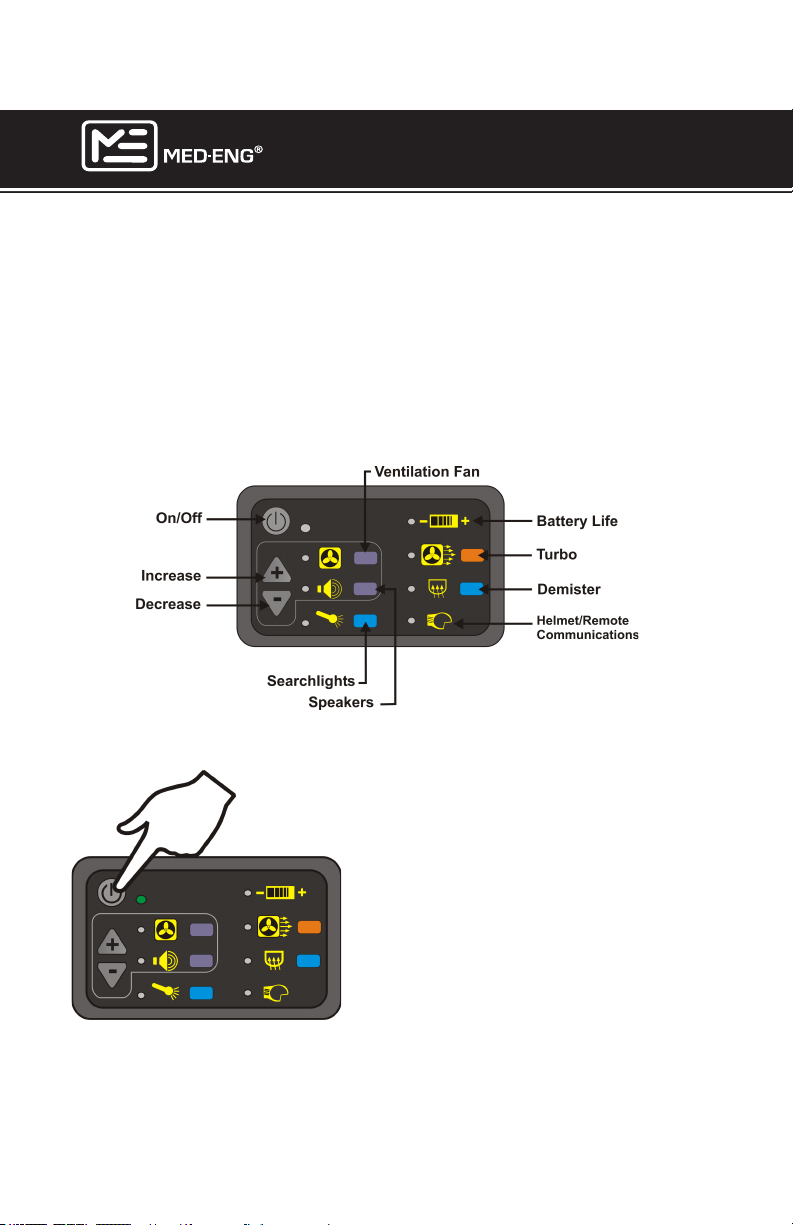
USING THE REMOTE CONTROLLER
NOTE: ONLY AN EOD®9 HELMET REMOTE CAN BE USED WITH THE
EOD®9 HELMET AND ONLY AN EOD®9A HELMET REMOTE CAN BE
USED WITH THE EOD®9A HELMET. REMOTES ARE NOT INTERCHANGEABLE. Position the Remote Controller on the forearm of either
sleeve depending on the preference of the technician. It is important that
the technician can easily view and access the remote. Secure the
VELCRO® strap and route the cable through the sleeve. Refer to Rout-
ing the Patchcord and Remote Control Cables in the
Preparation Section of this manual.
TURNING ON THE HELMET VIA THE REMOTE
Press the button indicated to supply power
to the system. Hold down the button for 1
second. All icons will illuminate yellow.
A green light beside the On/Off button indicates that the Remote Controller is receiving power. If the light is not illuminated, the
Remote Controller is not receiving power. A
red light indicates that the Remote Controller is faulty.
Power is automatically drawn from the SPS
(if connected) until that source is drained.
Power will then be drawn automatically
from the OPS.
Page 29
©2013 Med-Eng Holdings ULC. Company Proprietary and Condential
105-233 Rev J
Page 36
EOD® 9/9A HELMET
USER MANUAL
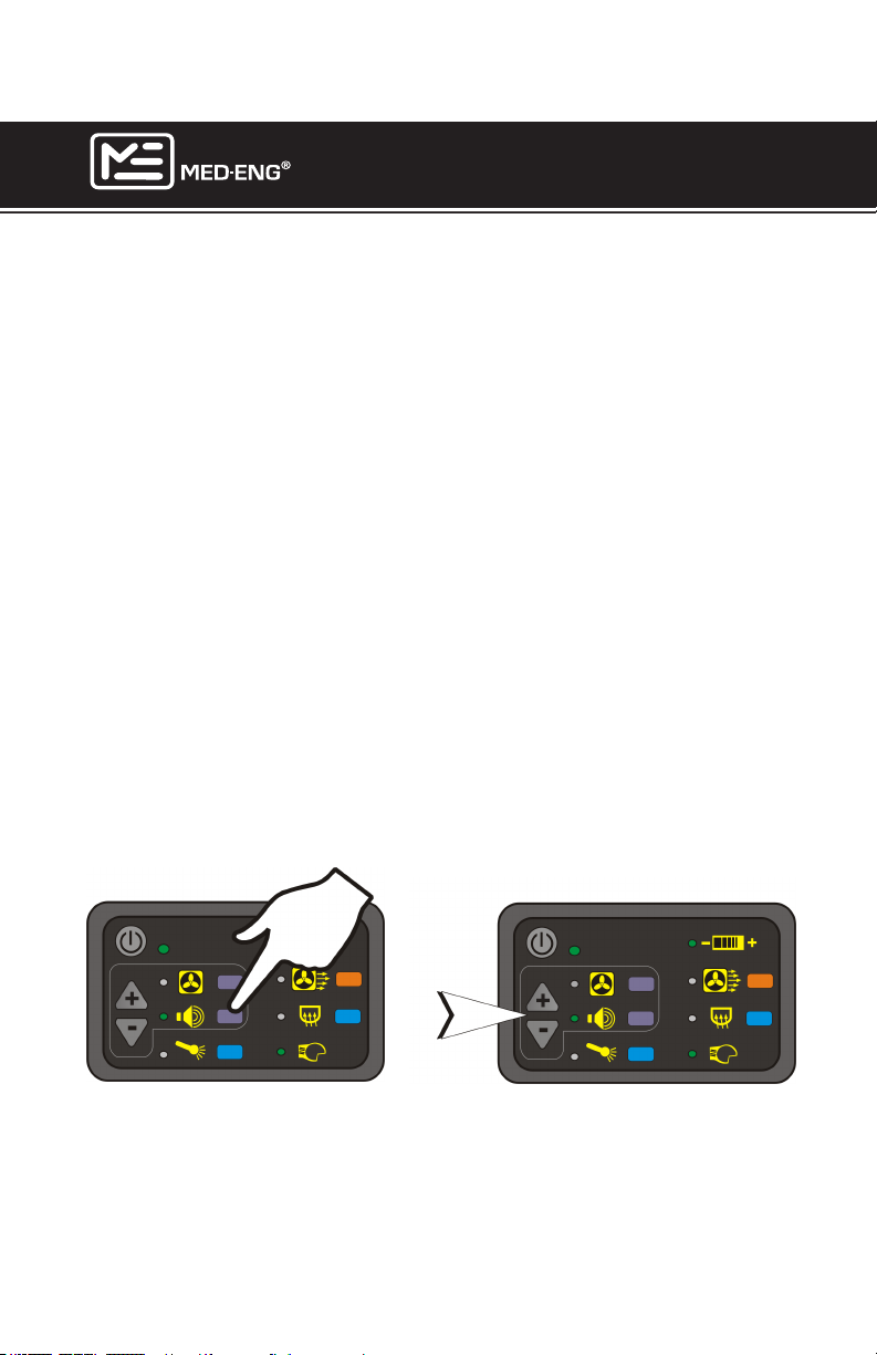
OPERATING THE SPEAKERS
The Environmental Awareness System (EAS) is linked to a stereo
headset system inside the helmet. Omnidirectional microphones and a
stereo amplication system allows the user to hear ambient sounds and
to distinguish from which direction a sound originates. The EAS is fully
compatible with duplex communication systems such as the HW-300 and
wireless systems. Automatic gain control (AGC) automatically increases
or decreases volume levels inside the helmet to ensure optimal sound
quality, as a function of ambient sound level. The EAS incorporates an
ambient sound amplier cut-out feature to block ambient sounds that
may damage the user’s hearing.
The speaker indicator light will illuminate automatically as soon as the
system is powered. A green light indicates that the function is active.
A red light indicates that the function is faulty. For the rst 30 seconds,
the increase/decrease buttons can adjust the speaker volume. After 30
seconds the speaker indicator light will switch off and the ventilation fan
light will switch on. To adjust speaker volume after this interval, press the
Speaker Key to activate the function for another 30 second interval. Then
use the increase/decrease keys to adjust volume.
Page 30
©2013 Med-Eng Holdings ULC. Company Proprietary and Condential
105-233 Rev J
Page 37
EOD® 9/9A HELMET
USER MANUAL
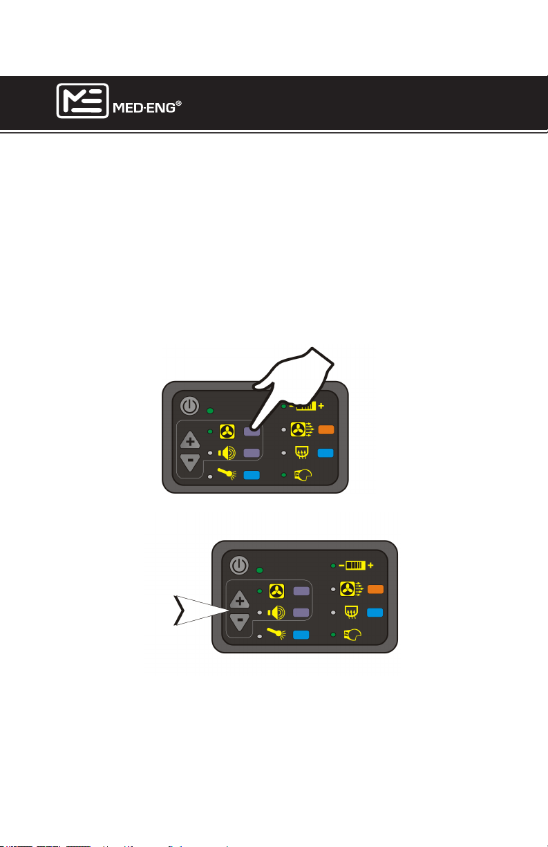
OPERATING THE VENTILATION FANS
Upon system initiation, the fan indicator light will illuminate automatically
after the speaker indicator light switches off (30 seconds after system
initiation). A green light indicates that the function is active; the increase/
decrease buttons can now be used to adjust fans at any time during
operation. A red light indicates that the function is faulty.
To switch to Fan Mode before the end of the 30-second Speaker Mode,
press the Fan Key then use the increase/decrease keys as desired.
Page 31
©2013 Med-Eng Holdings ULC. Company Proprietary and Condential
105-233 Rev J
Page 38
EOD® 9/9A HELMET
USER MANUAL
OPERATING THE SEARCHLIGHTS
WARNING: The use of any light is dangerous in the presence of
photoelectric cell activated explosive devices. If it is suspected that
such a device may be encountered, do not use the searchlights.
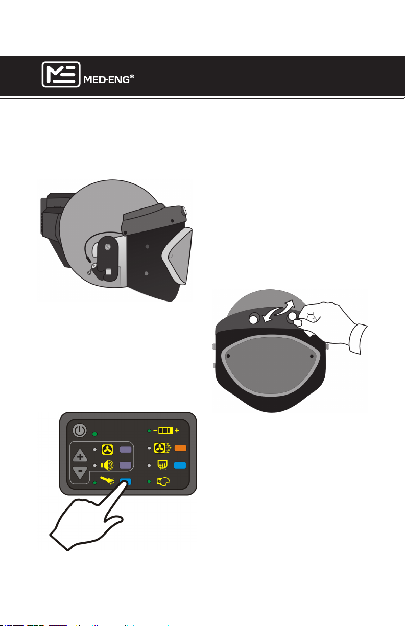
Searchlights are built into the top of
the visor and plug into the jack on
the right side of the helmet.
Note: When jack is not in use, insert
a dust cap. See page 2.
The angle of the searchlights can be
manually altered.
Page 32
Press the indicated button and hold
it down for 1 second to turn on the
searchlights.
If the indicator light turns red, check
to make sure the wire is plugged
into the jack.
©2013 Med-Eng Holdings ULC. Company Proprietary and Condential
105-233 Rev J
Page 39
EOD® 9/9A HELMET
USER MANUAL
OPERATING THE VISOR DEMISTER (OPTIONAL)
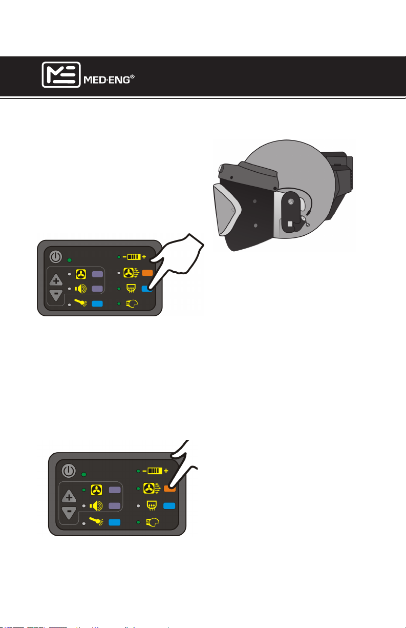
The Visor Demister plugs into the
jack on the left side of the helmet.
Note: When jack is not in use, insert
a dust cap. See page 27.
When activated via the remote controller,
the demister will run for 5 minutes if the
system is powered by the SPS, or 1 min-
WARNING: It is recommended to use the SPS (or
IPS) as a power source when
running the demister. The
demister will run on the OPS
alone, but will drain batteries
quickly.
ute if the system is powered by the OPS
only. When the system is powered by
the OPS only, the Turbo feature cannot
be activated while the demister is running. Press the button again to turn the
demister off before the standard interval
elapses.
Turbo Feature
Page 33
©2013 Med-Eng Holdings ULC. Company Proprietary and Condential
Press the button indicated on the
right to activate the Turbo feature.
Turbo will give a 25 second blast of
air to cool the user or defog the visor
if the demister is not in use. NOTE:
The turbo feature will not function
if the helmet is being powered by
the OPS only and the demister
is activated. Turbo speed may be
reduced near the end of battery life.
105-233 Rev J
Page 40
EOD® 9/9A HELMET
USER MANUAL
HELMET-REMOTE COMMUNICATIONS INDICATOR
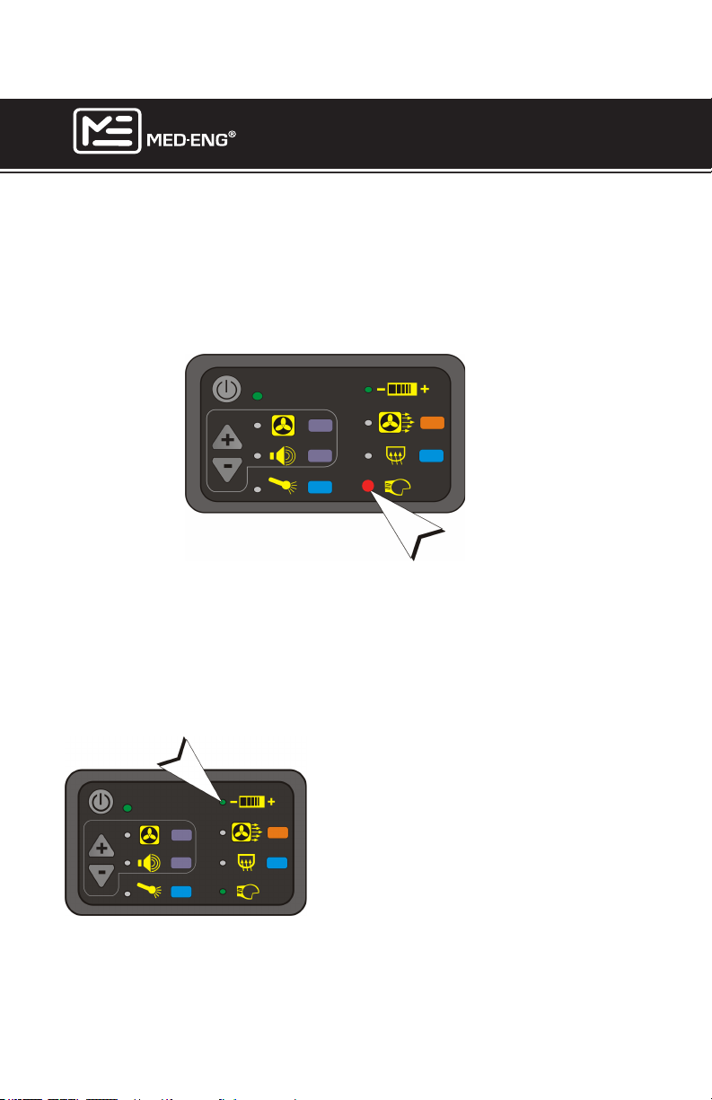
Under normal operating conditions, the Problem Indicator Light will illuminate green. This indicates that communications between the helmet and
the remote controller are functioning properly. A red light (A) indicates a
problem with communications between the helmet and the remote.
A
MONITORING BATTERY LIFE
The Battery Charge Light (B) toggles between green, yellow and red to
indicate the remaining battery charge of the source from which power is
being drawn. When the SPS is connected, power is automatically drawn
from this source rather than from the OPS. When the SPS has been
drained, power draw will automatically switch to the OPS. To determine
the charge of batteries in the OPS at any time, disconnect the SPS.
Green 75%-100%.
B
Yellow 25%-75%
Red 5%-25%
Page 34
NOTE: If the Battery life light is displaying low after fresh batteries have
been installed, open the back cover to
check that the battery switch is set for
the type of batteries installed (NiMH
vs Alkaline). If the switch is set incorrectly, the battery life indicator will not
provide an accurate reading.
©2013 Med-Eng Holdings ULC. Company Proprietary and Condential
105-233 Rev J
Page 41
EOD® 9/9A HELMET
USER MANUAL
SUGGESTED OPERATING/STORAGE CONDITIONS
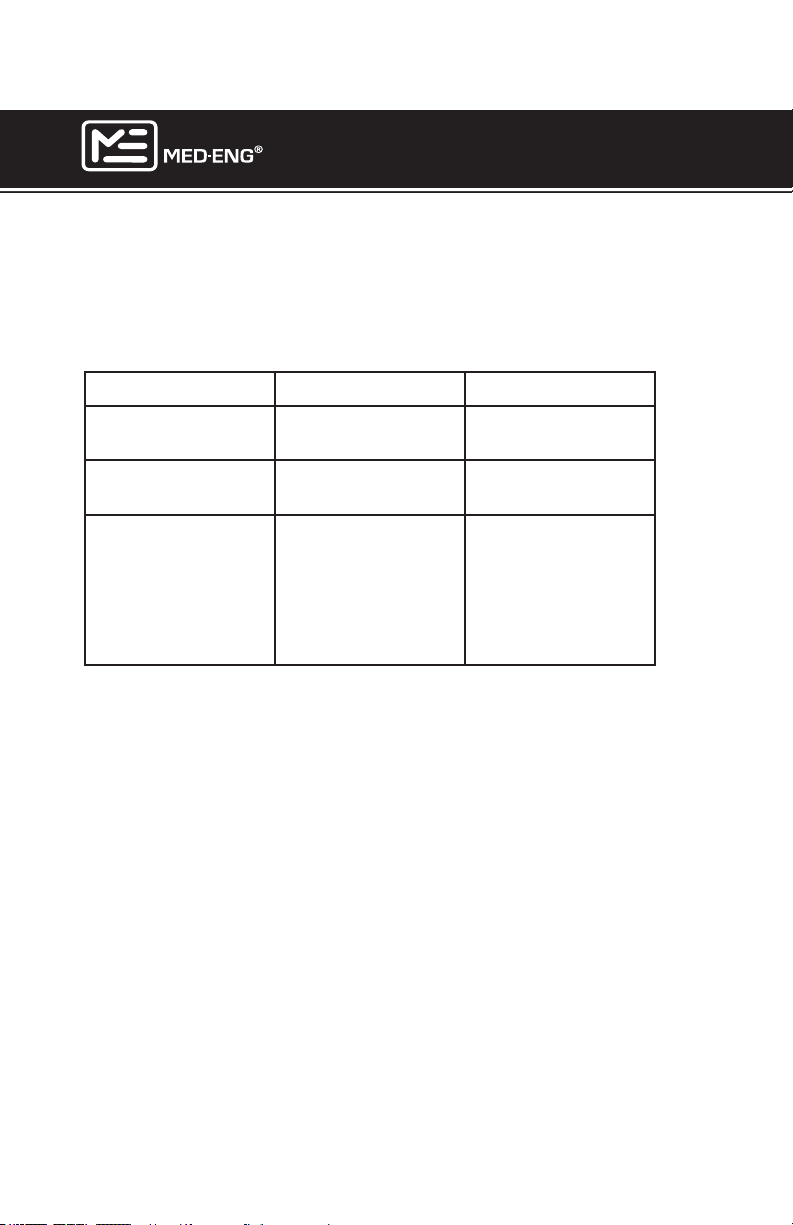
The EOD® 9/9A Helmet performs best if operated and stored under the
following conditions:
NOTE: Ensure batteries are removed before storage.
Temperature Humidity
Operating -20° to 40°C
(-4° to 104°F)
Storage -20° to 70°C
(-4° to 158°F)
Comments Battery capacity
may be reduced
if the temperature
is above or below
normal operating
conditions.
45% to 85%
35% to 85%
70% or less at
temperatures of
50°C (122°F) or
more.
Page 35
©2013 Med-Eng Holdings ULC. Company Proprietary and Condential
105-233 Rev J
Page 42

EOD® 9/9A HELMET
USER MANUAL
TROUBLESHOOTING GUIDE
System does not start up: the most common cause is insufcient
power.
- Cell orientation may not be correct; voltage below dead zone of 8V.
Check label for orientation & reinstall batteries correctly.
- Contact force on battery holder spring may be too weak. Refer to Pre-
ventative Maintenance.
- Cells may not be properly seated in the battery holder.
- Cells may be discharged. See section below.
- Remote controller is not connected properly.
System starts but operates for only a short time before shutting
down.
- Cells may be discharged; Open circuit voltage must be at least 8.4V on
NiMH setting and 10.5V on Alkaline setting. Preferred total battery potential
is 12V Alkaline and 10V NiMH.
- Chemistry selector switch is not set for the correct battery in use for both
SPS and OPS. If the OPS is used for backup to the SPS, ensure Chemistry switch setting is compatible for both sources (i.e. same type of battery is
used for both).
System does not respond to control.
- Ensure remote controller connector is fully inserted.
- Potential water or condensation inside electronics. Return for servicing.
Some system features do not operate.
- Check that the connector for the non-operating feature is fully inserted.
- Check the connector pins for worn contact plating, breakage or bending.
No sound on one side.
- Ensure that the speaker pad is properly aligned with the user’s ear.
- Ensure that the connector is fully inserted.
- Check speaker wire for damage
- Carefully remove speaker from ear pad, and check solder joints
Page 36
©2013 Med-Eng Holdings ULC. Company Proprietary and Condential
105-233 Rev J
Page 43
EOD® 9/9A HELMET
USER MANUAL
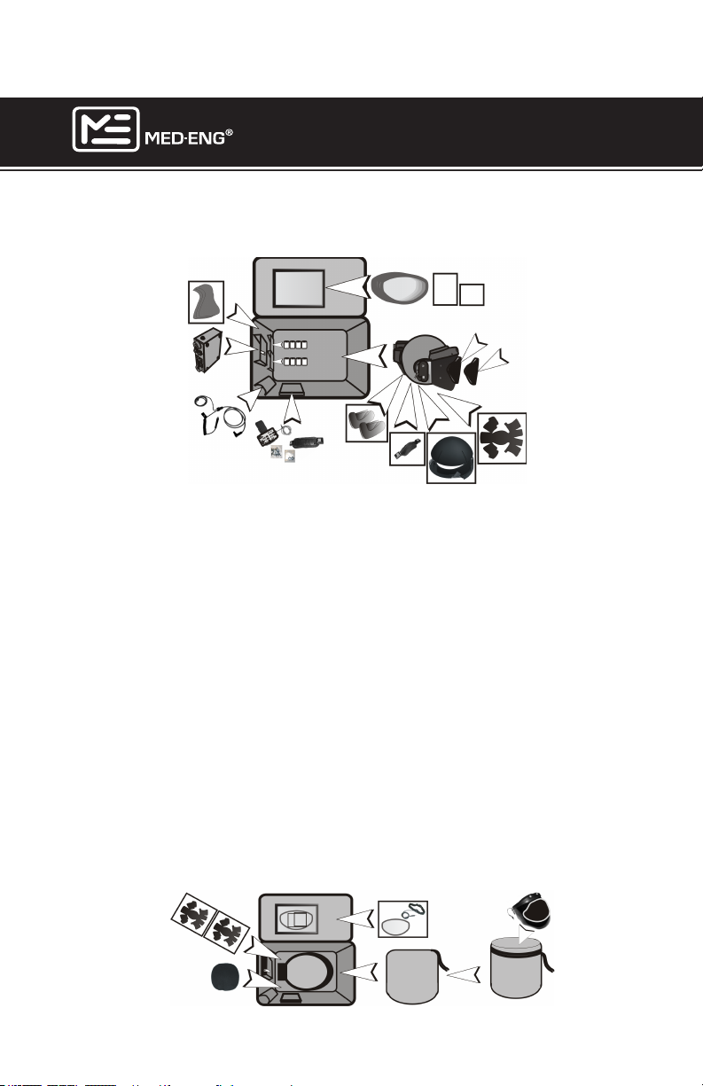
SUGGESTED PACKING PROCEDURE
Position the EOD® 9/9A Helmet components in the Carry Bag as
indicated:
Manual
DVD
Steel Visor (if applicable)
Visor Cover
1. Remove the batteries from SPS and discard in accordance with applicable disposal regulations or store in a manner to prevent the possibility
of short circuit. Make sure the SPS is snapped into the pocket.
2. Install the Visor Cover(s).
Note: If present, install the Steel Add-On as the visor cover. This will
prevent the steel add-on from moving around and damaging other
helmet components during transport.
3. Fasten the retention system and do not stack anything inside of the
helmet to prevent the visor from being scratched. Pack the bag with the
rest of the components as shown. Place the helmet in the carry bag so
that the visor faces away from the SPS.
NOTE: If shipping the helmet, cinch the retention system as tight as
it will go to prevent the visor from being scratched. It is also recommended that before shipping, a visor applique be applied. This will
also prevent the visor from being scratched.
4. Pack the BA Kit Bag in front of the helmet visor.
Page 37
©2013 Med-Eng Holdings ULC. Company Proprietary and Condential
105-233 Rev J
Page 44

EOD® 9/9A HELMET
USER MANUAL
CARE AND MAINTENANCE
PREVENTIVE MAINTENANCE
Always remove batteries from OPS and SPS after use.
Med-Eng strongly recommends the use of new alkaline or fully charged Ni-MH (Nickel-
Metal Hydride) batteries before each use. Whether a new or rechargeable battery is
used, Med-Eng suggests all batteries are examined for any signs of leakage, swelling,
off-gassing, corrosion, casing or any other damage prior to and post use. If any evidence of
damage, refer to Warning and Cautions in this document. Discard used or damaged batteries in accordance with local hazardous waste regulations should any evidence of damage
be noted.
Optimum temperature range for storing/charging NiMH cells is 10°C to 30°C. Charging is
disrupted below 0°C (and may be dangerous if vent cap leaks) or above 40°C.
- Never overcharge.
- Never reverse-charge cells.
- Never overdischarge at high current.
Prior to installing fresh AA cells, check that the battery holders are rmly secured to the
EAS plastic mold. If loose, re-secure the holders by tightening the #4 Phillips screws located below the battery orientation label. Do not over tighten screws and do not use thread
locker or cyanoacrylate adhesives to resecure the screws.
Check the battery holder clamp insertion force and cell contact tension from battery holder
terminals after each 30 insertions; if these forces are less than 50% of a new holder, carefully pinch the opposite ends of the terminals and squeeze the opposite ends together
approximately 1/8 inch to reset spring tension.
After every 10 battery insertions, clean the holder and battery contacts. Wipe the contacts
with isopropyl alcohol and a cotton swab. Visually inspect them and replace any corroded
hardware. Commercial batteries, used in missions where air temperature exceeds 40°C for
extended periods of time, can leak electrolyte. In this case, inspect and clean contacts after
each use. Be careful not to spread contamination on to printed circuit boards or connectors.
If it is necessary to transport the helmet or store it for a period of time, it is mandatory to
remove all batteries from the system and discard in accordance with applicable disposal
regulations or store in a manner to prevent the possibility of short circuit. If helmet is to be
shipped by air, lands, or sea, ensure compliance with applicable carrier’s battery transport
regulations.
Replace the air lter to the fan inlet when the light intensity from a 60W incandescent light
source passing through a dirty lter is less than ½ the light intensity of a new lter.
Check and retighten any loose screws which may be supporting connectors, fan mounts
and battery holders.
Page 38
©2013 Med-Eng Holdings ULC. Company Proprietary and Condential
105-233 Rev J
Page 45

EOD® 9/9A HELMET
USER MANUAL
CLEANING THE SPS AND REMOTE CONTROL
Wipe the SPS and the Remote Control with a damp cloth.
CLEANING THE VISOR
Use a soft cloth and a 5% solution of isopropyl alcohol in water, or a mild soapy solution
that does not contain ammonia, to clean the visor. Install the visor cover immediately after
each use to help prevent scratches. Avoid touching the surface of the visor with your hands.
Do not carry items in the helmet when the visor is installed as this could scratch the inner
surface.
CLEANING THE HELMET SHELL AND CHIN CUPS
Use a soft cloth and a 1% solution of isopropyl alcohol and water, or a mild soapy solution
that does not contain ammonia to clean the helmet shell.
CAUTION: The EOD® 9/9A Helmet may be damaged and rendered ineffective by
petroleum products, cleaning agents, paints or adhesives, etc., without damage being visible to the user. Med-Eng does not advise the use of paints, waxes, or other
chemicals on the EOD® 9/9A Helmet. Avoid the use of bleaches, cyanoacrylates,
solvent-based adhesives, and ammonia-based cleaning agents. If paints, decals, or
helmet modication is desired, rst contact Med-Eng.
CLEANING THE WASHABLE ITEMS
Comfort Liner, Crown & Sizing Pads - Remove items from the helmet and hand wash
with cold water and a mild soap solution. DO NOT USE BLEACH. DO NOT DRY CLEAN.
Rinse thoroughly with cold water to remove any accumulated soap. Hang to dry. Replace
the comfort liner and tpads only when completely dry.
Earpads - Remove speakers from earpads (see page 5) and hand wash with cold water
and a mild soap solution. DO NOT USE BLEACH. DO NOT DRY CLEAN. Rinse thoroughly
with cold water to remove any accumulated soap. Hang to dry. Replace the speakers only
when completely dry.
Balaclavas - Hand or machine wash in cold water using a mild detergent. DO NOT
BLEACH. DO NOT DRY CLEAN. Hang or machine dry on a low “tumble dry” setting.
Page 39
©2013 Med-Eng Holdings ULC. Company Proprietary and Condential
105-233 Rev J
Page 46
EOD® 9/9A HELMET
USER MANUAL
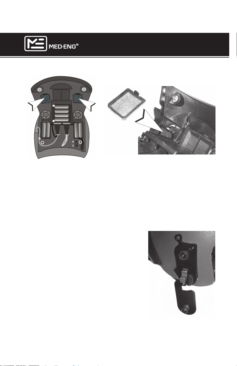
CLEANING AND REPLACING FILTERS
If the supply of fresh air into the helmet becomes reduced, inspect the lters. Filters can be rinsed in water. Do not use soap. Replacement lters are available
from Med-Eng. Make sure to replace lters so that the larger tab points upward.
Replace the air lter to the fan inlet when the light intensity from a 60W incandescent or equivalent light source passing through a dirty lter is less than ½ the
light intensity of a new lter.
REPLACING SHOCK ABSORBING VISOR PIVOTS
A set of replacement Shock Absorbing Visor
Pivots are supplied with each helmet. Replace pivots
if they become worn or the visor feels loose as it is
raised and lowered.
To replace the Visor Pivots:
Remove the visor to expose the visor pivots. (Refer
to the “Changing the Visor” section of this manual.)
Use a at blade (e.g. screwdriver or knife) to gently
pry off the old pivots. Press the replacement pivots
into position. Orientation does not matter.
Page 40
©2013 Med-Eng Holdings ULC. Company Proprietary and Condential
105-233 Rev J
Page 47

Page 48

EOD® 9/9A HELMET
Med-Eng Holdings ULC
2400 St. Laurent Blvd.
Ottawa, ON K1G 6C4
Canada
T 1.613.482.8835
1.855.633.3649 (US and Canada)
F 1.613.482.4991
USER MANUAL
www.med-eng.com
 Loading...