

Page 1
Service
Instructions
|
BASIC
036
Order
Nr.
190.0101b
MEDIAN
DOMINANT
046
056
medela
Page 2
Table
1.
2.
3.
4.
5.
6.
7.
of
Contents
Technical
Construction
Pneumatic
Electric
Trub
leshoot
Maintenance
Servicing
Dismat ing
Reassemb
Replacement
Service
Correcting
Spare
Drawings
Spare Parts
Parts
Data
Diagram
Circuit
ing
Procedures
and
ly
Piston/Cy
Flat-
Call
Indicator
an
List / Order
Diagrams
Cleaning
Linder
and
Toothed
Electronic
Piston/Cy
Unit
Be
Fault
Numbers
linder
lts
Unit
Page
3
4
5
6-
8-
9
10 - 13
10
11
11
11
12
13
14 - 19
14
17
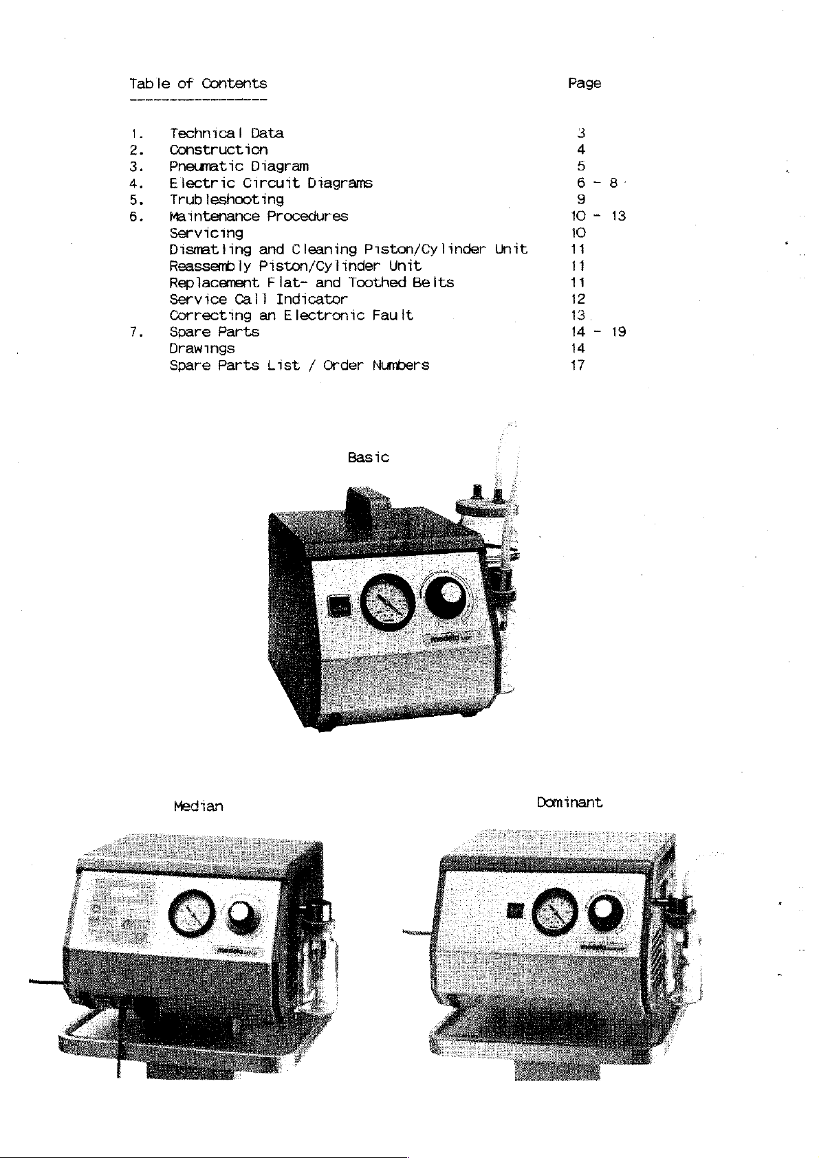
Median
Dominant
Page 3
.
Technica!
Data
Power
Electric
Power
Vacuum
Displacement:
Secretion
Surgical
Vacuum
Uterin
Low
Hight
Width
Depth
weight
Supply
Standard
Consumption
Range
Aspirator
Suction
Extractor
Aspirator
Vacuum
+ / -
Aspirator
*
Stand
and
Pump
.
and
Standard
Options
IEC
601.1 / Protection
100
W
5 - SO
20 1 /
| 一 一 一 一
一
一 一
10-80
20
267/984
240/420
324/480
8,4/20
mbar
1 / Min
kPa
Min
一
mm
mm
mm
kg
:
220 V /
:
see
5 -
30 1 /
see
see
10-80
20 1 /
227/944
325/494
324/616
sales
100
W
90
above
above
mbar
Min
10/21
50
Hz
literature
Class I or
kPa
Min
|
|
“|
m
mm
mm
kg
II
125
W
5 -
90
kPa
45 1 /
一
----------
-一 一 -一
227/944
325/494
324/616
10/21
Min
一 一 一
一
一
пт
mm
mm
kg
*
These
Baar/Ch,
barometric
table
figures
the
altitude
Location
Location
Factor
figures
444
pressure,
below
given
and
vacuum
are
based
meters
contains
must
of
the
reading
sea-
level
1.06
on
above
slight
several
be
multiplied
location
Basic
the
altitude
sea-level.
deviations
factors
where
According
as
by
one
measurements
1000m
036
of
our
in
measurements
reference
of
these
a.s1.1200Om
0.94
Median
046
|Dominant
production facilities
to
local
values.
factors,
are
conditions
may
The
according
caried
a.s1.|4000m
0.83
be
out.
noted.
vacuum
a.sl.
0.64
056
in
resp.
The
to
Page 4
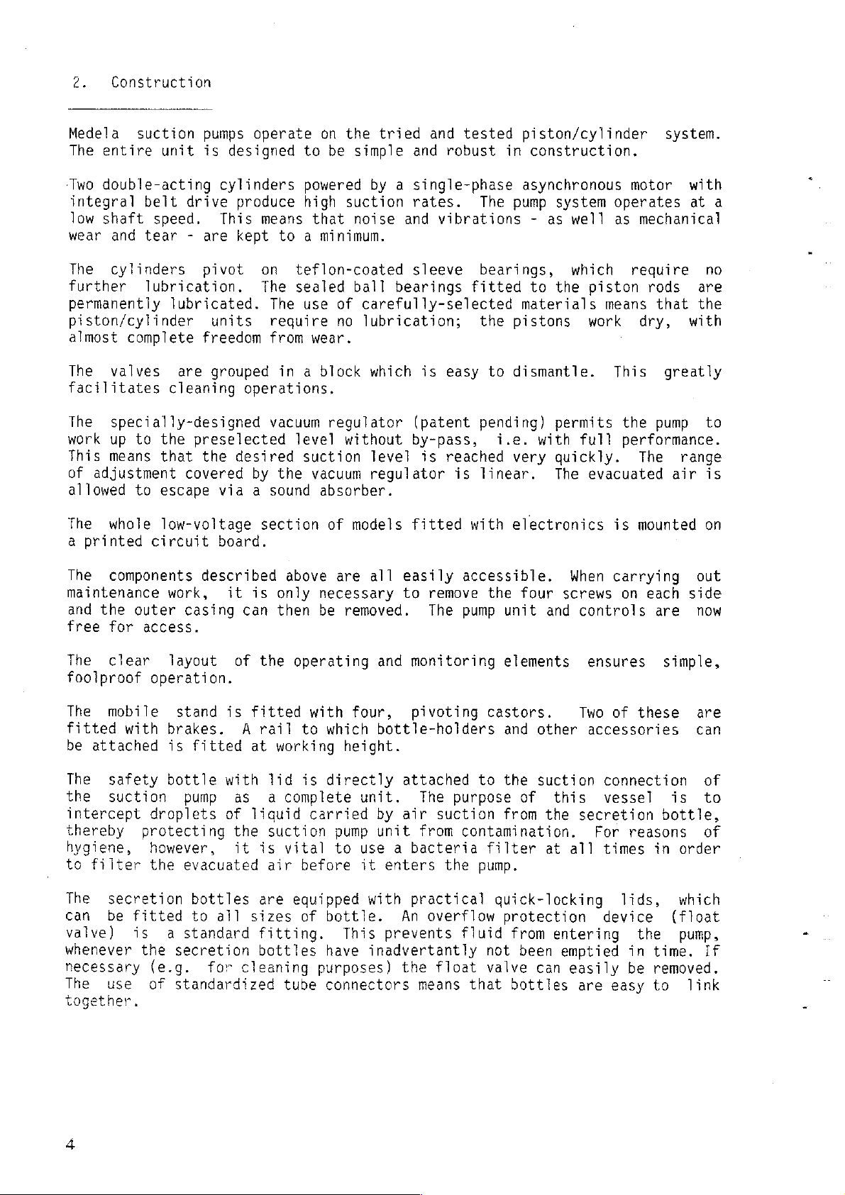
2.
Construction
Medela
The
‘Two
integral
low
wear
The
further
permanently
piston/cylinder
almost
The
suction
entire
double-acting
shaft
and
cylinders
unit
belt
speed.
tear - are
lubrication.
complete
valves
facilitates
The
specially-designed
work
This
of
The
a
up
means
adjustment
allowed
whole
printed
to
the
that
to
escape
low-voltage
circuit
pumps
is
designed
cylinders
drive
produce
This
kept
pivot
lubricated.
units
freedom
are
grouped
cleaning
preselected
the
desired
covered
via a sound
board.
operate
means
on
The
The use
require
from
on
to
powered
high
that
to a minimum.
teflon-coated
sealed
wear.
in a block
operations.
vacuum
level
suction
by
the
vacuum
absorber.
section
the
tried
be
simple
suction
noise
ball
of
carefully-selected
no
lubrication;
and
by a single-phase
rates.
and
sleeve
bearings
which
regulator
without
(patent
by-pass,
level
regulator
of
models
fitted
and
tested
robust
piston/cylinder
in
asynchronous
The
pump
vibrations - as
bearings,
fitted
materials
the
pistons
is
easy
to
dismantle.
pending)
i.e.
is
reached
is
with
very
linear.
electronics
construction.
to
system
well
which
the
operates
as
piston
means
work
This
permits
with
full
quickly.
The
evacuated
is
system.
motor
with
at
mechanical
require
rods
dry,
that
are
the
with
greatly
the
pump
performance.
The
range
air
mounted
a
no
to
is
on
The
components
maintenance
and
the
outer
free
for
The
clear
foolproof
The
mobile
fitted
be
The
the
with
attached
safety bottle
suction
intercept
thereby
hygiene,
to
filter
The
secretion
can
be
fitted
valve)
whenever
is a standard
necessary
The
together.
use
described
work,
casing
access.
layout
operation.
stand
brakes.
is
fitted
pump
droplets
protecting
however,
the
evacuated
bottles
to
the
secretion
(e.g.
of
for
standardized
above
it
is
only
can
then
of
the
operating
is
fitted
A
rail
to
at
working
with
lid
is
as a complete
of
liquid
the
suction
it is
all
air
are
sizes
vital
before
equipped
of
fitting.
bottles
cleaning
tube
are
all
necessary
be
removed.
with
four,
which
height.
directly
unit.
carried
pump
to
use a bacteria
it
with
bottle.
This
have
inadvertantly
purposes)
connectors
easily
to
and
monitoring
pivoting
bottle-holders
attached
The
by
air
unit
from
enters
accessible,
remove
The
pump
purpose
suction
contamination.
the
practical
An
overflow
prevents
the
means
fluid
float
that
the
four
unit
and
elements
castors.
and
other
to
the
suction
of
this
from
the
filter
pump.
at
quick-locking
protection
from
entering
not
been
valve
can
bottles
When
screws
controls
ensures
Two
accessories
connection
vessel
secretion
For
all
times
device
emptied
easily
are
carrying
on
each
are
of
these
reasons
in
lids,
the
in
time.
be
removed.
easy
to
out
side
now
simple,
are
can
of
is
to
bottle,
of
order
which
(float
pump,
If
link
Page 5

3.
Pneumatic
Diagram
Jdequosqy
punog
MOOLE
9ALBA
JEPULLÁD
BALUG
/
UOJSLd
O
UOLYDAUUOJ
UOLIONS
X
JOIN
UNNIEA
JOJE|NBBY
WNNOBA
Page 6

4.
Electric
A.
Without
circuit
electronics
diagrams
B.
Without
Protection
|
Ki
I/V
K
M
Schutzleiter
Getriebegehóuse
4
T
electronics
Class
|
Kit
|
/
|
|
K2
K2
E
\
II
„EP
Fw
FI
ES
TT
Schutzleiter
Geháuse
Fi
=
_FH1
ES»
F2
DI
「
|
|
|
|
IT
1
oe
Ld
「
|
si
|
|
|
|
È
|
K4 KS
7
|
(
M
)
“Aa
T
| |
| |
| |
+
|
|
|
+
(M
)
e
+
Los
K3
к
K5
С.
Without
connector
electronics,
for
foot
ion
Getriebegehduse
with
switch
FA
\Schutzleiter
Gehause
K15
pm
K
(a)
1
TT
/
KK 位 一
Fuss-Schalter
E
o
Li
2
Rel 2 Za
Е
o
K19
ОЗ
o
5
si
で
i
Page 7

D.
Without
(anaesthet
electronics,
ic-proof
)
АР
M
120
$
chutzleite:
Getriebegehduse
E.
Without
with
foot
7
|
V
X
г
electronics,
switch
e
LIE...
FH
F2
chutzteiter
Gehduse
AP
/
[2
1
ヒーーーー
blau
+
À
UA
|
|
71
7
/
κ
|
κό
|
|
4
y
K20
M
Schutzleiter
GetriebegehGuse
\"
E
4
the
\
—
F2
chutzieiter
GehGuse
LL
|
의
K12
=
|
K5
Page 8

F.
With
Bg
electronics
su
+
Ki
|
ュー
+
+
<a
1
т
KU
р
a
キーーー
ET
ee
ー
F2
FHI
Faz
|
er
La
1
BURSİN
|
|
|
|
|
|
ot
any
K7
si
|
n
1
lAs
K
1
|
K3a,
OI
À
G.
==>
With
st1
HA
e
Schutzleiter
Getriebegehůuse
electronics,
ки
|
A
N
D
IA
7
Schutzleiter
Getriebegehóuse
[|
AP
TES
一
レー
FI
ビー
Schutzleiter
Gehäuse
Ft
ュ
Fe
K
Schutzleiter
GehGuse
C1
κ.α.
La
A
|
51
SİNİ
^
7
«
~
(
Μ
Entlüftungs-
ventit
PT
|
|
|
|
L
o
Entiüf{ungs-
venti!
]
VET
VET
/
к
1
~
/
Ka
Ω
K6
|
|
|
|
1
K6
803
Bu?
st3
T
ué
|
iste
A
의
52
ul
Sté
16007
o]
|
Sté
3.
|
zg
|
pa
wh
|
|
bu
|
|
|
|
|
JU
E
|
245
1
status
.
1
S65jBus
3
MPG
|
|
|
|
D
|
|
|
|
SteBuê
(Bué
Externer
Schyester
Fülistand
Kİ
Service
8ut5|St45
к
-
>
|
|
|
|Finter
|
|
Exterer
Schalter
K7
gyz
Fülisland
[ция
고
還
KS
Service - |
|
80999
|
nota
|
оне
Lruf
24
エーー
ュ
Ban
|5
3
1
sumStT
H.
Foot
with
Switch
electronics
for
pumps
sus
5
4
m
i ㅣ
3
SH
59!
1
|
en
PT
|
Li
1
|
2
1
Page 9

5.
Troubleshooting
Problem
will
Motor
performance
suction
Inadequate
vacuum
a
run
not
however
Possible
Mains
Power
Electrical
Fuses
Drive
Electronic
Leak
external
External
Push-in
Safety
Air
Push-in
Tubing
Lids
Bottles
Bacteria
Filter
Internal
Tubing
Blockage
within
external
External
switch
supoly
unit
within
bottle
filter
paper
or
the
source
cord
jammed
fault
the
suction
cause:
connector
O-rings
O-rings
connectors
filter
cause:
mechanical
or
kink
pump
or
suction
cause:
of
trouble
pump
or
circuit
O-rings
housing
components
in
tubing
in
the
circuit
in
the
Check/action
Set
at
"ON"
Voltage,
Plug
connections,
cord
Type,
Summon
repair
See
Isolate
trouble
the
Section
Condition
Condition
Condition
No
Push
Cracks,
Airtight
Condition,
cracked
cracks
Condition,
leaks
Condition,
housing
Summon
repair
Isolate
trouble
Remove
from
suction
If
indicates
the
condition
page
checks
leaks
in
the
the
cause
technician,
service
by
6.
as
brittle
edges,
technician
service
as
the
pump;
connection
vacuum
to
power
type,
12/13
the
carrying
outlined
at
tube
far
fit
to
absence
position
source
follows:
safety
zero
is
external
be
socket
damaged
source
ends
as
stop
areas
bottle
passible
hairline
bottle
leave
gauge
vacuum
taken
plug
or
of
out
in
of
of
or
of
the
open,
now
=
suck,
indicates
not
gauge
does
Pump
Vacuum
Bacteria
Safety
Overflow
lid,
push-in
tubing,
Internal
Tubing
filter
bottle
valve
(float
connectors,
etc.
cause:
or
mechanical
in
valve)
the
components
Investigate
external
for
blockage(s),
valve
tubing
If
still
=
the
Summon
repair
sticking,
and
the
indicates
cause
service
the
suction
rectify.
vacuum
technician
is
internal
circuit
a
whole
float
kinked
gauge
vacuum
or
Page 10

6.
Maintenance
procedures
The
operating
To
by
as
pump
ensure
an
agent
belt
Servicing
The
following
end
of
this
General:
Disconnect
Release
Check
the
tear
the
flat
on
replaced
Check
Ensure
check
All
them
All
far
check
the
for
pieces
from
tubing
as
that
must
troublefree
hours
be
or
authorized
changing.
figures
manual.
the
electrical
the
eight
toothed
belt
the
according
sound
that
discoloration,
jamming
the
all
belt.
all
of
tubing
ends
stop,
pieces
(17).
absorber
tubing
must
given a routine service
at
screws
belt
If
the
to
the
or
kinking
extend
and
of
least
operation,
should
once
by
Medela.
refer
to
cord
(14)
(26)
after
Wipe
all
belt
special
(80)
connections
cracks
be
anywhere.
over
must
be
tubing
every
the
(7)
and
year.
repairs
This
also
drawings
from
remove
removing
surfaces
indicates
instructions.
and
remove
are
or
defective
of
adequate
the
full
free
are
from
routed
at
intervals
to
the
includes
and
the
mains
the
pump
the
free
of
excessive
any
dirt
clean,
connectors.
length
length
cracks.
freely
pump
the
supply.
housing
cover
dust
signs
if
both
and
of
By
without
of
approximately
may
only
cylinder
spare
parts'
(2).
plate
resulting
of
(43).
wear,
necessary.
inside
and
Replace
routed
the
connector
pulling
any
be
carried
cleaning
list
Also
from
it
outside,
if
necessary.
so
as
to
ferrule
on
them
kinks.
as
at
wear
must
prevent
gently,
1,000
out
well
the
check
and
be
and
as
ee
Enea
It
is
vital
that
only
ends
ensure
(3,10)
Valve
Undo
the
are
pushed
that
are
block:
the
tubing
genuine
knurled
replacements
compressed
prior
reassembly,
Please
If
that
Please
(53,
the
to
note:
sound
the
take
57,
valves
dismantled
Electrical
Ensure
Make
In
switch
Check
that
certain
the
case
housing
fuses
when
replacing a piece
Medela tubing
the
free
well
to
onto
pieces
move
nuts
if
the
or
cleaning
air.
Wash
reassembly.
dust
all
used
absorber
(62 - 65)
note
of
the
75)
to
the
and
cleaned
connections:
all
screw-
that
all
of AP
models
are not
(86).
the
ferrules
of
tubing
without
(4)
and
remove
inspection
are
required.
off
any
stubborn
Replace
and
new
(80)
and
the
and
the
section
vacuum
regulator
according
and
push-on
wiring
damaged,
insulation
(non-electronic),
of
tubing:
is
used
for
internal
as
far
(61,66)
any
kinks
measures
the
which
when
valve
Clean
dirt
any
damaged
rubber
tubing
pump
on
"Piston/cylinders"!
to
connections
i.e.
components
are
cylinder(s)
(73/74)
the
detail
is
intact
in
perfect
connections,
as
the
stop.
come from
the
motor
assembly
described
off
all
parts
with cold
rubber
Tightly
contaminated,
(3/10)
are
dirty,
drawing.
are
not
and
free
check
that
condition.
It is
the
(28)
(62-65).
above
of
water
seals
with
it
require
If
the
the
loose.
from
the
seals
pump
is
running.
indicate
the
and
dry
(63).
talc.
must
pieces
latter
damage.
and
that
important
cylinders
Only
remove
valves
all
Prior
be
assumed
cleaning.
of
tubing
must
on
the
the
to
that
with
items
to
et
be
power
10
Page 11

Piston/cylinder
unit:
dismantling
and
cleaning
Remove
Tne
to
cover
not
Dirt
agents!).
sealed
the
cylinders
the
cylinder
(104)
usually
and
deposits
The
for
screw
can
necessary
agents.
Black
a
black
surfaces.
polished
Warning:
surface-treated
discolorations
sign
of
powder
in
satisfactory
Using emery
the
The
Piston/cylinder
Warning:
No
lubricants
(49)
(3,10)
end
now
ball
life
and
is
the
direction
cylinder
and
unit:
together
can
covers
be
removed
to
can
be
bearing
must
on
the
lubrication
result
cloth,
wall
must
be
reassembly
may
be
removed
(91,92)
carry
removed
in
on
no
cylinder
of
extremely
the
of
piston
handled
be
used
with
spacers
by
and the
after
out any
and the
the
with
the
integral
account
wall
and
corresponding
travel.
accordingly.
in
the
(46 - 48).
gentle
pressure
cranks
screws
further
lukewarm
piston
come
should
small,
piston
into
(96)
not
course
Slacken
applied
(105).
(93)
have
dismantling
water
or
but
areas
rod
of
(do
rod/big
contact
on
the
be
removed.
sharp
should
have been
the
The
been
operations.
not
use
end
with
piston
The
ridges
be
very
following
screw
lower
released.
unit
on
very
(106).
simultaneously
cylinder
It is
any
cleaning
(105)
any
cleaning
rod
(105)
presence
the
rubbing
carefully
carefully
operations!
is
are
of
Reassemble
When
cold,
a
force
to
ensure
that
the
Replacement
If,
during
discovered
question
Flat
belt:
Rotate
the
Fit a new
motor
.
it,
the
Toothed
To
is
does
belt
belt:
change
instructions
flange
tension
cannot
The
attention
ring
is
be
drive
the
cylinders
it
must
of
between 6 -
that
two
must
the
cranks
of
flat-
servicing,
and/or
be
flat belt
belt
running,
not
centres
the
using
do
so,
toothed
above.)
(38)
determined
altered.
mechanism
to
the
be
possible
10
fine
coating
are
offset
and
the
inner
replaced.
pulley
the
i.e.
adjust
itself
during
belt
Then
via
the
by
the
is
reassembled
above
instructions
(3,10)
to
kg.
by
toothed
excessive
belt
(16)
same
method.
it
must
the
position
running,
(26),
unscrew
screws
distance
in
the
slide
The
on
the
90°.
belts
wear
face
by
not
first
(39)
reverse
the
piston
cylinders
sleeve
and
tear
shows
hand
and
The
belt
run
over
of
the
belt
remove
(40)
the
and
change
and
position
in
the
reverse
on
cylinder/piston
order
rods
must
be
bearings
(fine
clear
signs
withdraw
should
the
edge
motor
tension
the
cylinder
bearing
the
of
order.
to
that
described
(105)
refitted
is
not
rubber
of
wear,
the
belt
centre
of
the
via
the
is
automatically
(3).
cover
toothed
the
reassembly.
(41).
belt
toothed
Please
up
and
with
great
damaged!
particles)
the
(17)
itself
drive
screws
when
shaft.
(Refer
Remove
(26).
pulleys
pay
above.
down with
care
Ensure
are
belt
in
sideways.
the
If
(12).
If
correct.
to
the
the
Belt
and
careful
T
Page 12

Service
A.
Models
The
alarm
(bottles
—
Return
agent
described
-
The
also
triggered
-
The
also
B.
Models
call
indicator
without a liquid
indicates
not
emptied/mechanical
the
pump
for
dismantling
on
pages
internal
be
fuse
cancel
with a liquid
liquid
cleaned
off
again.
on
the
the
that
to
the
10/11.
sensor
and
dried,
back
of
visual
crystal
moisture
technical
and
cleaning.
(see
otherwise
the
service
crystal
display:
has
overflow
department
item
circuit
alarm.
display:
gained
The
access
valve
work
disassembled)
or a Medela
to be
121 / pages
the
same
board
must
(see
illustration
to
done
14/19)
service
be
replaced.
the
service
is
must
alarm
suction
.
will
This
p.
13)
unit
be
will
Several
with
-
Press
the
the
appear
alarm)
meaning:
reasons
aid
of
the
keys
vacuum
0 = No
1 = The
4 = Moisture
extractor
on
the
will
service
changed
(7)
display.
appear,
battery
(bottles
disassembled).
-
Return
service
done
~
The
internal
14/19)
same
-
For
resetting
and
briefly
circuit
means
now
ready
for
this
integral
and
has
not
the
agent
is
described
must
service
board.
of an
alarm
(2)
on
simultaneously.
When
together
required
on
the
gained
are
possible.
diagnostic
the
low
released, a symbolic
with
(as
there
PCB
(for
access
emptied/mechanical
pump
to
the
technical
for
desmantling
on
pages
liquid
also
alarm
the
sensor
be
cleaned
will
electronics,
short-circuit
This
resetting
acoustic
for
operation
signal
program
vacuum
a
to
pump
An
"S"
number
is
no
memory
the
overflow
and
10/11.
(see
and
be
triggered
switch
connections
operation
and
again.
The
cause
(*).
resp.
for
"Service"
"G"
with
alarm
and
suction
department
cleaning.
item
dried,
the
the
timer)
valve
121 / pages
otherwise
off
on
39
electronic
can
be
(1)
and
(reason
following
condition)
must
unit,
e.g.
or a Medela
The
again.
the
pump
and
54
is
acknowledged
system
traced
(3)
will
be
work
the
(K)
on
now
for
to
the
on
the
be
by
is
*
Note:
During
Return
pump)
12
the
to
resp.
diagnostic
normal
key 1 (vacuum
operation
phase,
extractor)
the
is
"Start/Stop"
effected
by
three
key
pressing
times.
cannot
key 7 (low
be
used.
vacuum
Page 13

correcting
A.
The
"Start/stop"
-
Check
~
Probably,
on
the
programs
eliminates
an
fuses
vacuum
the
electrical
(L).
keys
(7)
extractor
electronics
normal
key
does
The
main
and
control
fault
not
switch
(2)
on
were
to a help
functions.
funtion:
(K)
the
low
pressed
must
be
vacuum
simultaneously
setting
for
set
to
pump
resp.
servicing
"ON",
by
mistake.
(1)
and
purposes
(3)
This
and
Press
controlled
the
key
(7)
resp.
again
using
FRS
(a
|
INTERVAL
MEA
indicate
that
mains
unit
supply.
to
AO
B.
Electronics
-
It
is
peak
-
Connect
la)
possible
in
the
the
key
(1)
three
the
"Start/stop"
(a),
Lola
malfunctions:
supply.
other
the
programming
the
mains
times.
has
Set
key.
been
switch
The
pump
E
affected
(K)
can
now
he
by a voltage
set
to
"ON"
-
Briefly
operation
-
If
after
to
carried
short-circuit
is
the
electronic
this
has
restarting,
out
first
PCB-connections
acknowledged
system
been
done,
the
resetting
(shorting
by
means
does
the
operation
PCB-
of
not
return
circuit
connections
39
and
an
acoustic
to
normal
board
must
described
54.
This
signal.
be
above
39/54).
resetting
operation
replaced.
must
even
Prior
also
be
 Loading...