

Page 1

An ASSA ABLOY Group Company
Hybrid e-Cylinder
User Guide
Version 2.0
Part Number
LT-06047
Issue Date: January 28, 2008
Page 2

Medeco Hybrid User Guide
Table of Contents
1 Introduction....................................................................................................3
2 Design Description – Hybrid Main Control Unit (MCU)..................................4
3 Design Description – Hybrid Lock Cylinder (LCU).........................................5
4 Functional Description ...................................................................................5
4.1 IR Communications ................................................................................6
4.2 Master Key .............................................................................................6
4.3 User Keys...............................................................................................6
4.4 Non Volatile Memory Configuration........................................................6
4.5 User Groups...........................................................................................6
4.6 Key Validation Dates ..............................................................................7
4.7 Group Codes..........................................................................................7
4.8 Daily Time Zone Schedules....................................................................7
5 Access Control Operation..............................................................................7
5.1 LED Annunciations.................................................................................7
5.2 Low Battery Alarm..................................................................................8
5.3 Tamper Alarm.........................................................................................9
6 Installation Procedures – Mortise Application................................................9
6.1 What is required: ....................................................................................9
6.2 Installation procedure when MCU is programmed at the door................9
6.3 Procedure for programming an MCU prior to installation at door..........12
6.4 Installation procedure when MCU is programmed in advance..............13
7 Notifications.................................................................................................16
2 of 16
Page 3
Medeco Hybrid User Guide
1 Introduction
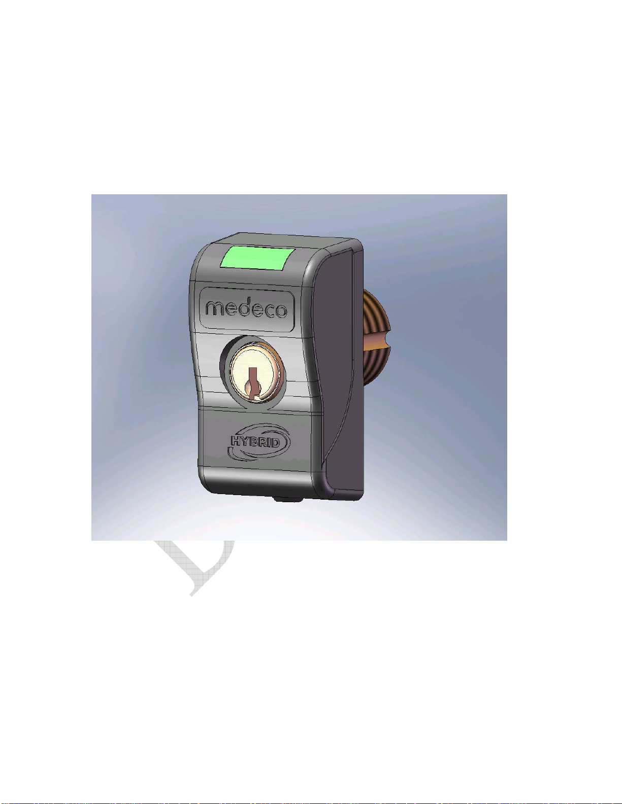
The Medeco/HID 125 kHz E-Cylinder is a battery operated RFID enabled electromechanical lock
(Figure 1). The unit as a whole is designed to be self-contained (no external wire or
communication connections) and operates to secure a door or entry portal. Access is granted on
the presentation of an authorized key (mechanical key and integrated transponder) to a master
control unit (Hybrid reader) which in turn, through secure communication, issues command for a
lock control unit (Lock Cylinder) to actuate a locking mechanism of a cylinder installed in said
door or entry portal.
Figure 1: Medeco/HID 125 kHz E-Cylinder (nested components)
The unit as a whole is generally comprised of five main subsystems; 1) the plastic
internal/external housings, 2) the electronic HW/FW circuit card assembly contained in the
internal/external housings, 3) mechanical lock cylinder engaged to door or entry portal hardware,
4) an electronic HW/FW circuit card module contained in the mechanical lock cylinder, and 5) an
access control credential (not shown) as illustrated in Figure 2.
3 of 16
Page 4
Medeco Hybrid User Guide
2 Design Description – Hybrid Main Control Unit (MCU)
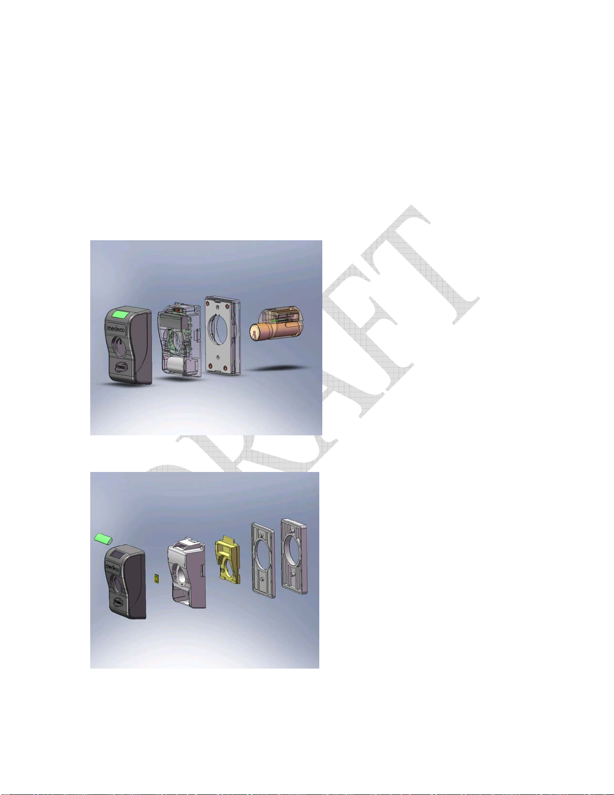
The Hybrid MCU consists of the following components illustrated in Figures 2 &
3. These items include:
Internal Housing with electronic module - MCU
External Housing cover
Rubber Insert
LED Lens
Anti-tamper Contact
Optional Spacer (thin)
Optional Spacer (thick)
Figure 2: The primary subsystems comprising the Medeco/HID 125 kHz E-Cylinder.
Figure 3: 3-D models of the components comprising the Medeco/HID 125kHz E-Cylinder Hybrid
Housing
4 of 16
Page 5
Medeco Hybrid User Guide
3 Design Description – Hybrid Lock Cylinder (LCU)
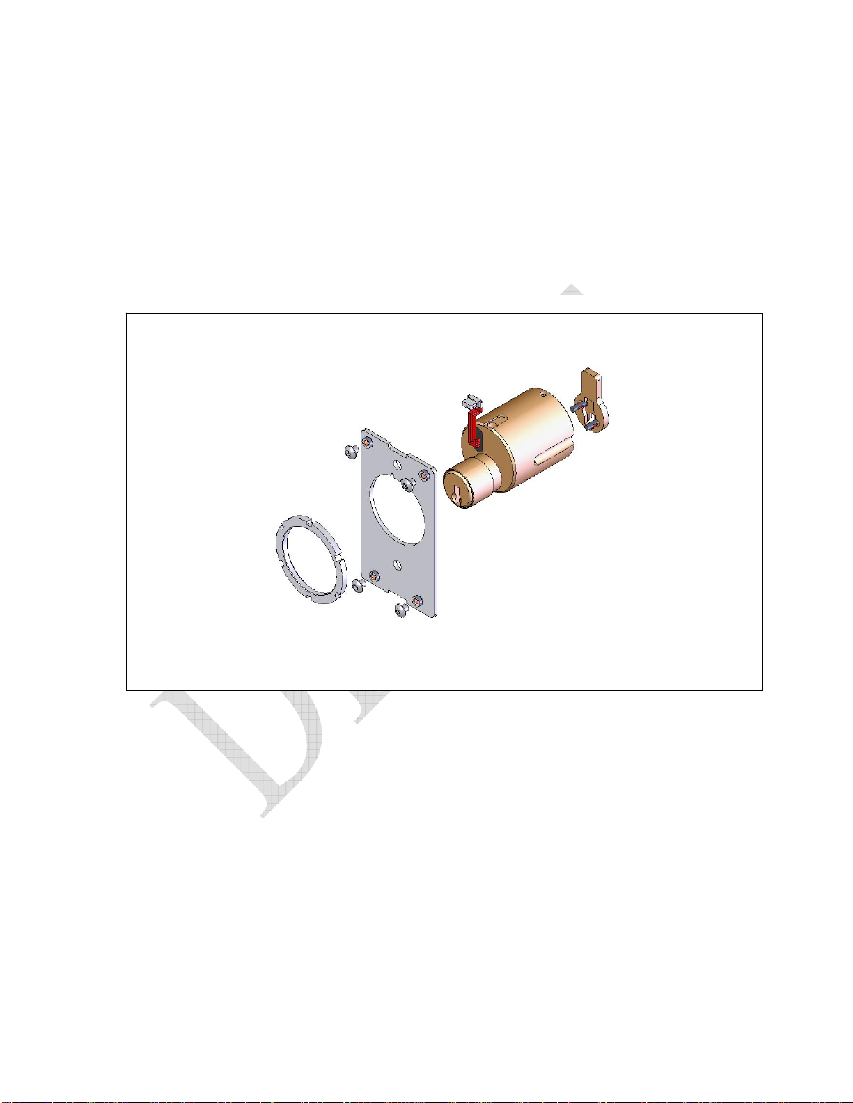
The Hybrid lock cylinder consists of the following components illustrated in Figure
4. These items include:
Lock Control Unit (LCU) – Including lock cylinder & electronics module
Lock CAM – specific to lock hardware type
Interface Cable – Hard wired to electronics module
Back plate
Locking Ring
Interface Cable
Lock Cylinder (LCU)
Back Plate
Locking Ring
Lock CAM
Figure 4: 3-D models of the components comprising the Medeco/HID 125kHz E-Cylinder lock
cylinder
4 Functional Description
The Medeco Hybrid MCU is a stand-alone prox reader that maintains a local
database of key and transaction information. Updates of valid key ID numbers
and communication of transaction information is performed using an Infrared
Communications interface. Other features of the cylinder include:
• 32kBytes of non-volatile memory providing a flexible combination of
key ID’s and transaction history.
• Programmable via an IR interface enabled by a “Master” key.
5 of 16
Page 6

Medeco Hybrid User Guide
• 3-level low battery alarm (alarm condition may be reset using a Master
key or using the IR interface)
• Access Control system for controlling access based on user groups,
valid entry times/dates.
• Tamper monitoring feature with temporary reader disable
4.1 IR Communications
The Hybrid MCU contains an IR communications port that allows programming of
the unit with user keys, schedules, holidays etc. as well providing for the transfer
of audit transaction data from the Hybrid to a PDA device. The IR
communications are initiated by the presentation of the Master Key.
4.2 Master Key
The Master key is used to initiate IR communications with the Hybrid reader and
to reset it in certain alarm conditions, but will not open the lock. The Master key is
always the first key in the database. The master key may be any (4-byte)
number. Its parameters default to Group = 0, Start date = 0, and End date = 0.
By default, the first tag read by the Hybrid reader at installation will be stored as
the master key.
4.3 User Keys
User keys are used strictly to open the lock. Each user key contains a key ID that
is checked by the MCU upon presentation to determine if access is allowed.
4.4 Non Volatile Memory Configuration
The Hybrid MCU contains 32kBytes of shared nonvolatile memory used for
configuration information, key ID database, and transaction history. The
maximum number of audit events stored in the transaction history is derived from
the memory leftover after setting the number of user keys.
4.5 User Groups
The Hybrid MCU allows segmentation of user keys into groups. Groups allow
authorization of users to be day, date, and time dependent. There are a total of
10 possible group numbers (0-9).
• Group0, strictly speaking, is not a valid Group Code. It is reserved for the
Master Key and is assigned by the e-cylinder. If a User key has a group #
of 0 it will be rejected.
• Group1 is authorized 24hours/day 7 days a week. (Key Validation Date
checking still applies).
• Groups 2-9 can be given authorization within 4 separate time windows per
day of the week. In addition, each of the groups 2-9 has an associated
code that indicates whether or not Holidays, extended open periods or
closed periods are to be enabled for that group.
6 of 16
Page 7

Medeco Hybrid User Guide
4.6 Key Validation Dates
Each user key in the database is given a start date and end date. If the current
date is within that window then the group parameters & permissions will be
checked. Otherwise the key will be rejected. Groups 1-9 are all subject to
validation date checking. The Master Key (Group 0) is not.
4.7 Group Codes
Each Group Number 2-9 has an associated Group Code. (Group Numbers 0 & 1
do not have an associated Group Code). The Group Code indicates whether or
not Holidays should be checked before access is granted.
4.8 Daily Time Zone Schedules
Each Group Number 2-9 has 4 time zones per day of the week during which
access may be granted. The time zones are check last, and apply even if a key
has passed all validation checks.
Each time zone is specified by a Start time and an End time.
4.8.1 Start Hours and End Hours entries are (0-23)
Start Min and End Min entries are (0-59)
Day of the week proceeds from Sunday to Saturday. (0-6)
5 Access Control Operation
Each key ID stored in the database has an associated group number (0-9) and a
start and end validation date.
When a key is read by the Hybrid reader, a decision to grant or deny access is
made. Below is a brief overview of this decision process. (assumes the key is a
user key, not the master key.)
• Find the key in the database
• Check the validation dates
• Check the Group #, otherwise reject the key.
o If the Group# = 0 & tag is not the master then reject the tag.
(Except for the master tag)
o If the Group# = 1 then accept the tag and unlock 24/7.
o If the Group# = 2-9
check holidays if the associated Group Code is enabled
Check 4 Daily Time zones for the group
5.1 LED Annunciations
The following table describes the annunciations for the Hybrid reader. All LED
signals will be flashing. The rate and duration are noted in the comments
(Number of Flashes, On Time (ms), off Time (ms)).
7 of 16
Page 8

Medeco Hybrid User Guide
Table 1. LED Annunciations
Description LED Comments
Normal Active State OFF
Access Mode
Access Granted Green 4 flashes, On:30ms, Off: 220ms
Access Denied
(ID not in Database, Not Registered, etc)
Access Denied
(Out of Schedule)
Red 4 flashes, On:30ms, Off: 220ms
Red 2 flashes, On:30ms, Off: 470ms
False Detect (wake & read but no tag found) OFF
Program Mode (IRDA)
Master Key Valid Green 2 flashes, On:30ms, Off: 100ms
Operation Success & Terminate Green 2 flashes, On:30ms, Off: 100ms
Operation Error, MCU Timeout Red 2 flashes, On:30ms, Off: 100ms
MCU – LCU Registration Error Red 10 flashes, On: 30ms, Off:
470ms
(Suggested Alternative to
indefinite Flashing)
Low Battery
Warning – Open Green,
Green: 1 flash, On:30ms, Off:
Amber
220ms
Amber:3 flashes, On:30ms, Off:
220ms
Warning – No Open Red,
Amber
Red: 1 flash, On:30ms, Off:
220ms
Amber:3 flashes, On:30ms, Off:
220ms
Battery< minimum voltage None Shut down MCU & LCU
Clock Invalid Will open on with master tag.
(see master Credential)
Tamper Detected None low power state.
5.2 Low Battery Alarm
The Hybrid MCU will monitor the battery voltage at power up and at timed
intervals thereafter. If a low battery condition is detected a transaction will be
stored and the Hybrid MCU will change the LED to the pre-defined color for a low
battery condition. If the battery is determined to be below its minimum operating
8 of 16
Page 9

Medeco Hybrid User Guide
value, the Hybrid MCU will be shut down to a minimum power state with no keydetection.
5.3 Tamper Alarm
The Hybrid MCU contains tamper circuitry that detects if the outer cover is
removed or power is lost for any reason. If the tamper condition is detected a
transaction will be stored. A tamper condition will cause the Hybrid MCU to reject
all user keys until reset by presentation of the Master key.
6 Installation Procedures – Mortise Application
For the purposes of these instructions the Hybrid reader assembly (inner
housing) is referred to as the MCU and the Hybrid lock cylinder assembly is
referred to as the LCU.
6.1 What is required:
Hybrid installation kit
Lock cylinder assembly with proper cam (LCU)
Reader unit (MCU)
Outer cover
Housing spacers
Base plate
Lock Ring
Mounting screws
Battery
User key with correct mechanical keyway and cut
Hybrid 125KHz Prox key head
PDA programming device
Programmed from the Hybrid Manager software
Including access rights for the User Key
The functionality to set the MCU clock
Hybrid Manager Software (Not covered in this document)
6.2 Installation procedure when MCU is programmed at the door
6.2.1 Remove mechanical cylinder from lockset. (if applicable)
6.2.2 Verify proper cam on Hybrid cylinder for target lockset.
9 of 16
Page 10

Medeco Hybrid User Guide
6.2.3 Rotate cam on back of Hybrid cylinder to home (locked) position – This
removes the cylinder from the shipping (unlocked) position and
mechanically “arms” the Hybrid cylinder. A properly bitted key must now
be used to operate the lock cylinder.
6.2.4 Install (screw) the Hybrid cylinder into the lockset. Check for operation
with the lockset using the User key to operate the cylinder mechanically.
Adjust the cylinder as necessary for door thickness, cam engagement, etc.
6.2.5 When cylinder adjustments are complete, tighten set screw in lockset to
secure cylinder in place.
6.2.6 Install base plate and lock ring to secure lock cylinder to door. Install
spacers as required for thin door applications.
6.2.7 Place cylinder in locked position and remove the User key. User key is no
longer needed until Hybrid unit is programmed.
6.2.8 Ensure the battery is removed from the MCU unit.
6.2.9 Connect the cable from the LCU to the back of the MCU unit.
6.2.10 Locate and install the MCU onto the base plate using the four mounting
screws. Care must be taken to ensure the interconnect cable is routed
properly behind MCU and is not damaged.
6.2.11 Install the battery into the MCU
6.2.12 MCU will power up and flash the LED red, yellow, green - one sequence.
6.2.13 The MCU will power up in tamper condition.
The LCU will power up and “arm” the electronic blocking mechanism (mechanical
key alone will no longer operate lock)
6.2.14 Install the MCU outer cover
The tamper switch will be reset
10 of 16
Page 11

Medeco Hybrid User Guide
The MCU will start to search (ping) for a key
At this point:
MCU is still in tamper mode
MCU has no master key identified and stored
MCU and LCU are not registered to each other
MCU and LCU are not authorized with each other
MCU clock is not set
MCU is not programmed with a key list, schedules, etc.
6.2.15 Present the Master key to the MCU – The master key should be the same
used for all other Hybrid locks in this installation (customer site)
MCU reads and stores the key as its master – It remains the master key unless
reprogrammed later. The LED will flash green for 3 cycles to indicate the master
key was accepted.
MCU resets the tamper condition
MCU registers with the LCU
MCU establishes authorization with the LCU
MCU turns on the IR communications port. The MCU will flash the LED red when
the IR communications session times out.
6.2.16 Program the Hybrid with the PDA – PDA should be loaded with key list
(including User key used for installation)
6.2.17 Present the PDA to the MCU – IR port on PDA must be active
6.2.18 Present the master key to the MCU
The MCU reads the master key, flashes the LED green and turns on the IR
communications port
The PDA communicates with the MCU via the IR link and uploads a key list and
schedules etc. into the MCU
The PDA sets the clock in the MCU
The MCU will flash the LED green at the completion of the communications
session.
11 of 16
Page 12

Medeco Hybrid User Guide
(The MCU will flash the LED red if the IR communications session times out prior
to completing the communications session.)
The Hybrid unit is now functional and ready for use
6.2.19 Present the User key to test the function of Hybrid unit with the lockset
6.3 Procedure for programming an MCU prior to installation at door.
Note: LCU is not connected or utilized in the advance programming of the MCU.
If the LCU is connected to the MCU during this process the two components will
register to each other and require the installer to keep the MCU and LCU
together as a matched pair until installed onto the door.
6.3.1 Install battery into MCU
MCU will power up and flash the LED red, yellow, green - one sequence.
The MCU will power up in tamper condition.
6.3.2 Install the MCU outer cover
The tamper switch will be reset
The MCU will start to search (ping) for a key
At this point:
MCU is still in tamper mode
MCU has no master key identified and stored
MCU and LCU are not registered to each other – No LCU connected
MCU and LCU are not authorized with each other – No LCU connected
MCU clock is not set
MCU is not programmed with a key list, schedules, etc.
6.3.3 Present the Master key to the MCU – The master key should be the same
used for all other Hybrid locks in this installation (customer site)
MCU reads and stores the key as its master key – It remains the master key
unless reprogrammed later.
12 of 16
Page 13

Medeco Hybrid User Guide
The MCU flashes the LED green, red, green to indicate the master key was
accepted but no LCU was found.
MCU resets the tamper condition
MCU turns on the IR communications port - The MCU will flash the LED red
when the IR communications session times out.
6.3.4 Program the Hybrid unit with the PDA – PDA should be loaded with key
list (including User key used for installation)
6.3.5 Present the PDA to the MCU – IR port on PDA must be active
6.3.6 Present the master key to the MCU
MCU reads the master key and flashes LED green, red, green to indicate (Master
key valid, No LCU connected, IR port turned on)
The PDA communicates with the MCU via the IR link and uploads a key list and
schedules etc. into the MCU
The PDA sets the clock in the MCU
The MCU will flash LED green at the completion of the communications session.
(The MCU will flash the LED red if the IR communications session times out prior
to completing the communications session.)
Note: The MCU battery should be removed until the unit is installed at the door.
6.4 Installation procedure when MCU is programmed in advance.
6.4.1 Remove mechanical cylinder from lockset. (if applicable)
6.4.2 Verify proper cam on Hybrid cylinder for lockset.
13 of 16
Page 14

Medeco Hybrid User Guide
6.4.3 Rotate cam on back of Hybrid cylinder to home position – This removes
the cylinder from the shipping (unlocked) position and mechanically “arms”
the Hybrid cylinder. A properly bitted key must now be used to operate
lock cylinder.
6.4.4 Install (screw) the Hybrid cylinder into the lockset. Check for operation
with the lockset using the User key to operate the cylinder mechanically.
Adjust the cylinder as necessary for door thickness, cam engagement, etc.
6.4.5 When cylinder adjustments are complete, tighten set screw in lockset to
secure cylinder in place.
6.4.6 Install base plate and lock ring to secure lock cylinder to door. Install
spacers as required for thin door applications.
6.4.7 Place cylinder in locked position and remove the User key. User key is no
longer needed until Hybrid install is completed.
6.4.8 Ensure the battery is removed from the MCU unit.
6.4.9 Connect the cable from the cylinder to the back of the MCU unit.
6.4.10 Locate and install the MCU onto the base plate using four screws. Care
must be taken to ensure the interconnect cable is routed properly behind
MCU and is not damaged.
6.4.11 Install the battery into the MCU
MCU will power up and flash the LED red, yellow, green - one sequence.
The MCU will power up in tamper condition.
The LCU will power up and “arm” the electronic blocking mechanism (mechanical
key alone will no longer operate lock)
6.4.12 Install the MCU outer cover
The tamper switch will be reset
14 of 16
Page 15

Medeco Hybrid User Guide
The MCU will start to search (ping) for a key
At this point:
MCU is still in tamper mode
MCU has a master key previously identified and stored
MCU and LCU are not registered to each other
MCU and LCU are not authorized with each other
MCU clock is not set
MCU already programmed with a key list, schedules, etc.
6.4.13 Register the MCU and LCU, set clock and reset tamper with PDA
6.4.14 Present the PDA to the MCU – IR port on PDA must be active
6.4.15 Present the master key to the MCU
MCU reads the master key and flashes LED green to indicate master key
accepted and turns on the IR port.
MCU resets the tamper condition
MCU registers with the LCU
MCU establishes authorization with the LCU
The PDA communicates with the MCU via the IR link and sets the clock in the
MCU
The MCU will flash LED green at the completion of the communications session.
(The MCU will flash the LED red if the IR communications session times out prior
to completing the communications session.)
The Hybrid unit is now functional and ready for use
6.4.16 Present the User key to test the function of Hybrid unit with the lockset
15 of 16
Page 16

Medeco Hybrid User Guide
7 Notifications
This device complies with Part 15 of the FCC Rules. Operation is subject to the
following two conditions: (1) this device may not cause harmful interference, and
(2) this device must accept any interference received, including interference that
may cause undesired operation.
Operation is subject to the following two conditions: (1) this device may not cause
interference, and (2) this device must accept any interference, including
interference that may cause undesired operation of the device.
If any changes or modifications not expressly approved by the party responsible
for compliance could void the user's authority to operate the equipment.
2008 by Medeco Security Locks, Inc.
All rights reserved
Medeco Security Locks, Inc.
PO Box 3075
3625 Allegheny Drive
Salem, VA 24153
Direct comments and corrections to:
E-Cylinder Technical Support
Voice:
1-888-6-MEDECO
(1-888-663-3326)
Fax:
540-380-1637
16 of 16
 Loading...