

Page 1
105109-01 Rev A
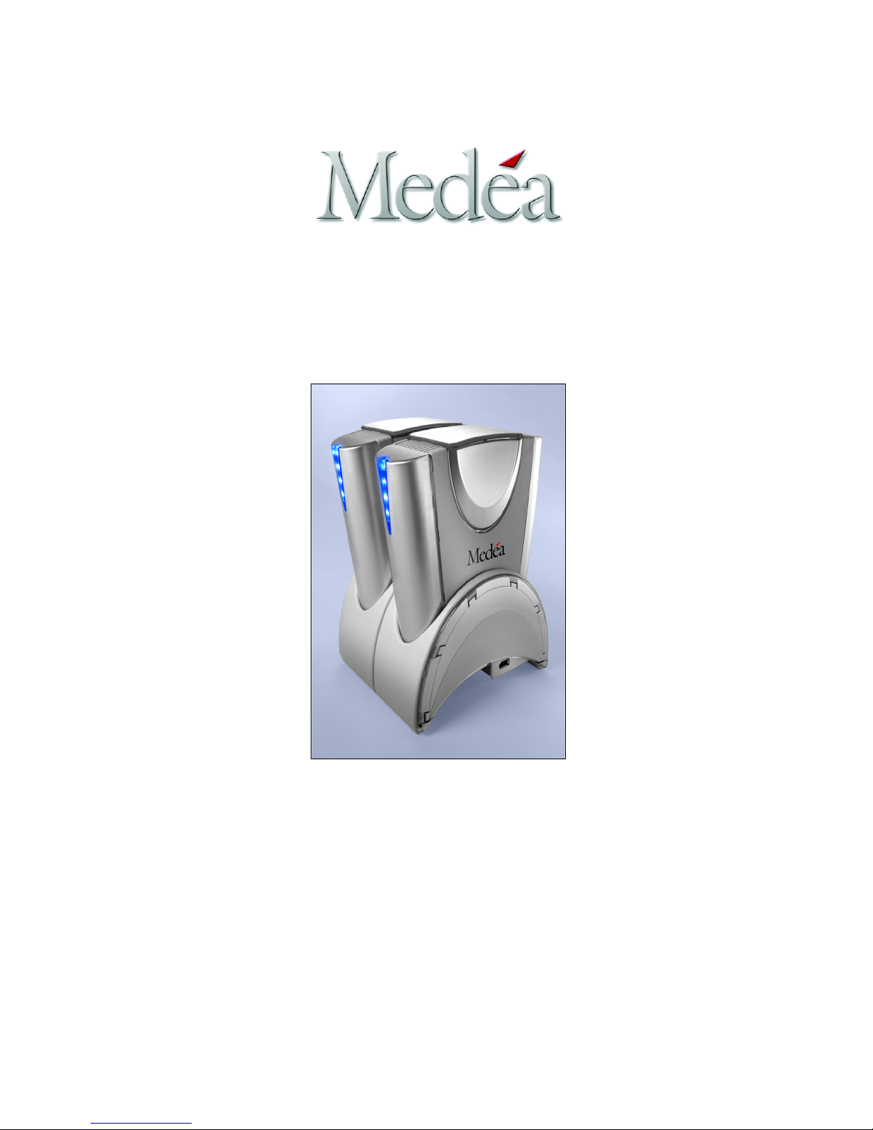
FireFly
Installation Guide
Medéa Corporation Technical Support
818-880-0303
Fax: 818-880-6906
Page 2
IMPORTANT SAFEGUARDS
CAUTION
RISK OF ELECTRIC SHOCK
DO NOT OPEN
CAUTION:
TO REDUCE THE RISK OF ELECTRIC SHOCK, DO
NOT REMOVE COVER (OR BACK). NO USERSERVICEABLE PARTS INSIDE. REFER SERVICING
TO QUALIFIED SERVICE PERSONNEL.
WARNING: TO REDUCE THE RISK OF FIRE OR ELECTRIC SHOCK, DO NOT EXPOSE APPLIANCE TO RAIN OR MOISTURE.
The lightning flash with arrowhead symbol within an equilateral triangle is intended to
alert the user to the presence of uninsulated dangerous voltage within the product
enclosure that may be of sufficient magnitude to constitute a risk of electric shock to
persons.
The exclamation point within an equilateral triangle is intended to alert the user to the
presence of important operating maintenance (servicing) instructions literature
accompanying the appliance.
1. READ INSTRUCTIONS
All the safety and operating instructions
should be read before the unit is operated.
2. RETAIN INSTRUCTIONS
The safety and operating instructions should
be retained for future reference.
3. HEED WARNINGS
All Warnings on the unit and in the operating
instructions should be adhered to.
4. FOLLOW INSTRUCTIONS
All operating and use instructions should be
followed.
5. ATTACHMENTS
Do not use attachments not recommended by
the unit’s manufacturer as they may cause
hazards.
6. WATER AND MOISTURE
Do not use this unit near water–for example,
near a bathtub, washbowl, kitchen sink or
laundry tub, in a wet basement or near a
swimming pool.
7. ACCESSORIES
Do not place this unit on an unstable cart,
stand, tripod, bracket or table. The unit may
fall, causing serious injury and serious damage
to the unit.
8. VENTILATION
Openings in the front and back of the unit are
provided for ventilation to ensure reliable
operation and to protect it from over heating.
These openings must not be blocked or
covered. This unit should never be placed near
or over a radiator or heat source. This unit
should not be placed in a built-in installation
such as a bookcase or rack unless proper
ventilation is provided.
9. POWER SOURCES
This unit should be operated only from the type
of power source indicated on the rating label. If
you are not sure of the type of power supply in your
facility, consult your local dealer or power company.
10.GROUNDING AND POLARIZATION
This equipment is supplied with a power cord with a
US style 3-wire grounding type plug at one end and
a 3-wire IEC standard connector at the other. The 3wire grounding type plug will fit into a US style
grounding type power outlet and the IEC connector
is intended to plug into the Medéa unit. The 3-wire
grounding type plug is a safety feature. If you are
unable to insert the plug into the outlet, do not force
it. Contact your electrician to replace the obsolete
outlet. DO NOT DEFEAT THE SAFETY PURPOSE
OF THE GROUNDING TYPE PLUG. For use in
Foreign Countries, contact your local Medéa dealer
or representative to obtain a power cord with a
locally compatible 3-wire grounding plug on one end
and a 3-wire IEC standard connector on the other.
11. POWER-CORD PROTECTION
Power-supply cords should be routed so that they
are not likely to be walked on or pinched by items
placed upon or against them, paying particular
attention to cords at plugs, convenience receptacles
and the point where they exit the unit.
12.SERVICING
Do not attempt to service this unit yourself as opening
or removing covers may expose you to dangerous
voltages or other hazards. (See Caution Symbol at
rear of power supply chasis.) Refer all servicing to
qualified service personnel.
13.LITHIUM BATTERY
CAUTION: Danger of explosion if battery is
incorrectly replaced. Replace only with the same or
equivalent type. Dispose of used batteries according
to the manufacturer’s instructions.
14.CAUTION
Before replacing Power Supply 1 or Power Supply 2
Module, ensure that the associated Power Switch
(PS1 or PS2) is in the off position and the associated
Power Cord is removed.
Page 3
WICHTIGE SICHERHEITSHINWEISE
WARNUNG
Gefahr eines elektrischen
Schlages Nicht öffnen
WARNUNG:
Um die Gefahr eines elektrischen Schlages zu verringern
sollten Sie niemals eine Verkleidung oder Abdeckung
entfernen. Keines der enthaltenen Teile kann selbst
gewartet werden. Überlassen Sie dies qualifiziertem
Servicepersonal.
WARNUNG:
UM DIE GEFAHR EINES ELEKTRISCHEN SCHLAGES ZU VERRINGERN, DARF DAS GERÄT WEDER REGEN NOCH FEUCHTIGKEIT
AUSGESETZT WERDEN.
Dieses Symbol soll den Benutzer darauf aufmerksam machen, dass er hier unisolierte
gefährliche Spannung innerhalb des Gehäuses antrifft, die ausreichend gefährlich ist um
einen Stromschlag hervorzurufen.
Dieses Symbol ist gedacht um den Anwender darauf hinzuweisen, dass sich im
Handbuch wichtige Hinweise befinden.
1. LESEN SIE DIE HINWEISE
Lesen Sie bitte alle Sicherheitshinweise und die
Bedienungsanleitung bevor Sie das Gerät in
Betrieb nehmen.
2. AUFBEWAHREN DER HINWEISE
Bewahren Sie die Bedienungsanleitung und alle
Sicherheitshinweise für spätere Verwendung auf.
3. BEACHTEN SIE DIE WARNUNGEN
Alle Warnungen and Hinweise auf dem Gehäuse
und in der Anleitung sollten unter allen
Umständen beachtet werden.
4. FOLGEN SIE DEN ANWEISUNGEN
Alle Benutzer -und Bedienungsanweisungen
sollten befolgt werden.
5. ERWEITERUNGEN
Benutzen Sie keine Erweiterungen, die nicht
vom Hersteller empfohlen wurden um Gefahren
zu vermeiden.
6. WASSER UND FEUCHTIGKEIT
Benutzen Sie das Gerät nicht in der Nähe von
Wasser–z.B. Badewanne, Waschschüssel,
Spüle, Waschwanne, feuchter Fußboden oder
in der nähe eines Pools.
7. ZUBEHÖR
Stellen Sie das Gerät nicht auf einen wackeligen
Rollcontainer, Ständer, Stativ, Regal oder Tisch.
Das Gerät könnte herunterfallen, was einen
bleibenden bzw. irreparablen Schaden an dem
Gerät hervorrufen könnte.
8. BELÜFTUNG
Öffnungen an der Vor- und Rückseite des
Gerätes sind für die Belüftung vorgesehen, um
eine zuverlässige Funktion zu garantieren und
gegen Überhitzung vorzubeugen. Diese
Öffnungen dürfen weder verstellt noch
zugedeckt werden. Das Gerät sollte niemals in
der Nähe einer Heizung oder einer anderen
Wärmequelle aufgestellt werden. Das Gerät
sollte außerdem nicht in einem Einbaugehäuse
wie einem Schrank, oder einem Rack installiert
werden, solange eine ausreichende Belüftung
nicht sichergestellt ist.
9. NETZANSCHLUß (STROMVERSORGUNG)
Das Gerät sollte nur mit der Spannungsversorgung,
die auf dem Geräteaufkleber ausgewiesen ist,
betrieben werden. Sollten Sie nicht sicher sein,
welche Art der Spannungsversorgung in Ihrem
Betrieb ver wendet wird, fragen Sie bei Ihrem
Händler oder der Stromversorgungsgesellschaft
nach.
10.ERDUNG UND POLUNG
Zur Ausstattung gehört ein Stromkabel mit einem
amerikanischen Schutzkontakt Stecker mit Erdung
auf der einen Seite und einem Kaltgeräte Stecker
auf der anderen (IEC Standard). Der
Schutzkontaktstecker passt in eine amerikanische
Schutzkontaktsteckdose und de Kaltgerätestecker in
ihr Medea Gerät. Der Schutzkontaktstecker ist eine
Sicherheitseinrichtung. Sollten Sie ihn nicht ich Ihre
Steckdose stecken können, wenden Sie keine
Gewalt an. Setzen Sie sich mit Ihrem Elektriker in
Verbindung um die Steckdose auszuwechseln.
Zerstören Sie unter keinen Umständen die
Sicherheitseinrichtung an Ihrem Stecker. Zur
Anwendung in anderen Ländern setzen Sie sich mit
Ihrem Medea Händler in Verbindung, der Ihnen ein
Landesübliches Stromkabel mit einem
Schutzkontaktstecker auf der einen und einem
Kaltgerätestecker auf der anderen Seite zur
Verfügung stellt.
11. STROMKABEL ISOLIERUNG
Stromkabel sollten so gelegt werden, dass man nicht
auf sie tritt, oder Geganstände auf ihnen stehen
bzw. gegen sie stoßen. Besondere Aufmerksamkeit
sollte Leitungen und Steckern, sowie Kupplungen
und die Stelle an der sie das Gerät verlassen,
gewidment werden.
12.SERVICE
Versuchen Sie keinesfalls das Gerät selbständig zu
warten, oder das Gehäuse zu öffnen. Dies kann Sie
gefährlicher Spannung oder andern Gefahren
aussetzen. Überlassen sie alle Wartungsarbeiten
qualifiziertem Service Personal.
13.LITHIUM BATTERY
VORSICHT! Explosionsqefahr bei unsachgemä
Bem Austausch der Batterie. Ersatz nur durch
denselben oder einen Vom Hersteller empfohlenen
gleichwertigen Typ. Entsorgung gebrauchter
Batterien nach Angaben des Herstellers.
14.ACHTUNG
Vor dem Austausch der Netzteile (Power Supply 1
oder Power Supply 2) bitte sicherstellen, dass der
jeweilige Netzschalter (Power Switch 1 oder Power
Switch 2) in Position „off“ ist, und dass das
entsprechende Netzkabel abgezogen wurde.
Page 4
10.PUESTAA TIERRA Y POLARIZACIÓN
El equipo se entrega con un cable alimentador con
un enchufe con puesta a tierra de 3 alambres en un
extremo y un enchufe estándar IEC (Comité
Electrotécnico Internacional) de tres alambres en el
otro. El enchufe con puesta a tierra de 3 alambres
se conecta a un tomacorri ente con puesta a tierra y
el conector IEC tiene por objeto enchufarse a una
unidad Medea. El enchufe con puesta a tierra de 3
alambres es una medida de seguridad. Si no le es
posible conectar el enchufe a un tomacorriente, no
lo fuerce. Póngase en contacto con un electricista
para sustituir el tomacorriente obsoleto. NO FRUSTRE
LA MEDIDA DE SEGURIDAD INCORPORADA POR
EL ENCHUFE CON PUESTA A TIERRA. Para uso en
países extranjeros, póngase en contacto con su
distribuidor local de Medea o su representante para
obtener un cable alimentador con un enchufe con
puesta a tierra de 3 alambres en un extremo y un
enchufe estándar IEC de tres alambres en el otro
compatible en su país.
11. PROTECCIÓN DEL CABLE ALIMENTADOR
Los cables alimentadores se deberán de colocar de
manera que se evite que sean pisados o pellizcados
por algún equipo o mueble puestos encima de ellos o
contra ellos, poniendo especial atención al enchufe
del cable alimentador, receptáculos de protección o el
punto en que se conectan a la unidad.
12.SERVCIOS
No intente dar servicio a esta unidad por sí mismo
en virtud de que abrir la unidad o retirar alguna
cubierta lo puede exponer a voltajes peli grosos u
otros riesgos. Permita que el servicio lo realice
personal de servicio calificado.
13.LA PILA DE LITIO
PRECAUCIÓN: Existe gran peligro de explosión si
la pila se reemplaza incorrectamente. Reemplácela
únicamente con el mismo modelo o su equivalente
exacto. Deseche la pila anterior según las
instrucciones del fabricante.
14.PRECAUCIÓN
Antes de reemplazar las fuentes de poder 1 ó 2,
asegúrese de que el interruptor correspondiente
(PS1 o PS2) esté en la posición “apagado” y que el
cable correspondiente también haya sido removido.
MEDIDAS PREVENTIVAS IMPORTANTES
PRECAUCIÓN
RIESGO DE DESCARGA ELÉCTRICA
NO ABRIR
PARA REDUCIR EL RIESGO DE DESCARGA ELÉCTRICA,
NO RETIRE LA CUBIERTA (O CUBIERTA POSTERIOR). NO
HAY ADENTRO PARTES REPARABLES POR EL USUARIO.
PERMITA QUE EL SERVICIO LO REALICE PERSONAL DE
SERVICIO CALIFICADO.
ADVERTENCIA:
PARA PREVENIR LA POSIBILIDAD DE PROVOCAR UN INCENDIO O DE RECIBIR UNA DESCARGA ELÉCTRICA, NO EXPONGA ESTE
SISTEMA A LA LLUVIA O HUMEDAD.
El símbolo del rayo con flecha dentro de un triángulo equilátero tiene por objeto alertar al usuario de la
presencia de voltaje peligroso y sin aislamiento en el interior del producto que pudiera ser de la suficiente magnitud como para constituir el riesgo de recibir una descarga eléctrica.
El símbolo de el signo de exclamación dentro de un triángulo equilátero tiene por objeto alertar al
usuario de la existencia de instrucciones importantes para la operación y mantenimiento (servicios) en
los documentos que acompañan el equipo.
1. LEA LAS INSTRUCCIONES
Deberá leer todas las instrucciones sobre
seguridad y operación antes de operar la
unidad.
2. GUARDAR LAS INSTRUCCIONES
Deberá guardar las instrucciones sobre
seguridad y operación para refer encia futura.
3. PRESTE ATENCIÓN AADVERTENCIAS
Deberá cumplir con todas las Advertencias
indicadas en la unidad o en las instrucciones de
operación.
4. SIGA LAS INSTRUCCIONES
Deberá seguir todas las instrucciones sobre
operación y uso.
5. ACCESORIOS
No utilice accesorios que no hayan sido
recomendados por el fabricante de la unidad en
virtud de que pueden crear un peligro.
6. AGUA Y HUMEDAD
No utilice esta unidad cerca de agua—por
ejemplo, cerca de una tina, lavabo, fregadero o
tinaco, en un sótano mojado o cerca de una
piscina.
7. EQUIPO AUXILIAR
No coloque esta unidad sobre carritos, bases,
trípodes, soportes o mesas inestables. La
unidad se podrá caer, causando lesiones
graves y daños severos a la unidad.
8. VENTILACIÓN
Aberturas al frente y en la parte posterior de la
unidad se proporcionan para ventilación y para
asegurar una operación estable, así como para
proteger a la unidad de sobrecalentamiento.
Estas aberturas no deberán ser obstruidas o
cubiertas. Esta unidad nunca se deberá de
colocar cerca o encima de un radiador o fuente
de calor. Esta unidad no se deberá de colocar
en muebles construidos a la medida, tales
como libreros o estantes, salvo que se
proporcione ventilación adecuada.
9. FUENTES DE ENERGÍA
La unidad deberá operar únicamente a partir del
tipo de fuente de energía indicada en la etiqueta
correspondiente. Si no está seguro del tipo de
fuente de energía en su edificio, consulte a su
distribuidor local o compañía de suministro de
energía eléctrica.
PRECAUCIÓN:
Page 5
MISES EN GARDE IMPORTANTES
ATTENTION
RISQUE DE CHOC ÉLECTRIQUE
NE PAS OUVRIR
AFIN DE PRÉVENIR LES RISQUES D’ÉLECTROCUTION, NE PAS
ENLEVER LE COUVERCLE (NI LE PANNEAU ARRIÈRE) DE L’APPAREIL.
AUCUNE PIÈCE INTÉRIEURE NE PEUT ÊTRE RÉPARÉE PAR
L’UTILISATEUR. POUR TOUTE RÉPARATION, CONSULTER UN
TECHNICIEN COMPÉTENT.
MISE EN GARDE:
AFIN DE PRÉVENIR TOUT RISQUE D’INCENDIE OU D’ÉLECTROCUTION, NE PAS EXPOSER L’APPAREIL À LA PLUIE NI À L’HUMIDITÉ.
Le symbole d’éclair dans un triangle équilatéral indique la présence d’une tension suffisamment élevée pour engendrer un risque de chocs
électriques.
Le point d’exclamation dans un triangle équilatéral indique que le manuel d’utilisation
inclus avec l’appareil contient d’importantes recommandations quant au fonctionnement
et à l’entretien de ce dernier.
1. LIRE LES DIRECTIVES
Lire toutes les directives concernant la sécurité
et le fonctionnement de l’appareil avant de l’utiliser.
2. CONSERVER LES DIRECTIVES
Conserver les directives concernant la sécurité
et le fonctionnement de l’appareil pour
référence ultérieure.
3. RESPECTER LES MISES EN GARDE
Respecter toutes les mises en garde sur
l’appareil et dans le manuel d’utilisation.
4. SUIVRE LES DIRECTIVES
Suivre toutes les directives concernant le
fonctionnement et l’utilisation de l’appareil.
5. ACCESSOIRES
Ne pas utiliser d’accessoires non recommandés
par le fabricant de l’appareil, car ils peuvent
représenter un danger.
6. EAU ET HUMIDITÉ
Ne pas utiliser l’appareil dans un endroit où il
risque d’être mouillé, notamment dans un
sous-sol humide et à proximité d’une baignoire,
d’un lavabo, d’un évier, d’une cuve à lessive ou
d’une piscine.
7. BAIES ET SUPPORTS
Ne pas placer l’appareil dans une baie ou sur
un support, un trépied, une console ou une
table instable. L’appareil pourrait tomber et
subir des dommages importants ou infliger de
graves blessures.
8. AÉRATION
Le boîtier de l’appareil comporte des fentes
d’aération à l’avant et à l’arrière pour assurer le
bon fonctionnement de l’appareil et le protéger
de la surchauffe. Ces fentes ne doivent pas être
obstruées ni recouvertes. Éloigner l’appareil de
toute source de chaleur telle les radiateurs et
autres éléments de chauffage. Ne pas placer
l’appareil dans un meuble encastré tel une
bibliothèque ou un bâti qui ne procure pas une
aération adéquate.
9. ALIMENTATION
Ne brancher l’appareil que dans une prise de
courant du type décrit sur l’étiquette
signalétique. En cas de doute sur le type
ATTENTION:
d’alimentation disponible, consulter la
compagnie d’électricité ou le distributeur local.
10.MISE À LA TERRE ET POLARISATION
Le cordon d’alimentation fourni avec l’appareil
est doté d’une fiche polarisée à trois branch
es de style américain à une extrémité et d’un
connecteur femelle CEI standard à l’autre
extrémité. La fiche polarisée à trois branches
peut être branchée dans une prise de
courant polarisée de style américain et le
connecteur CEI doit être rac cordé à l’appareil
Medea. La fiche polarisée à trois branches
constitue une mesure de sécurité. Si elle ne
s’insère pas aisément dans la prise, ne pas
la forcer. Contacter un électricien pour
remplacer la prise désuète. NE PAS TENTER
DE CONTOURNER CETTE MESURE DE
SÉCURITÉ. Pour utiliser l’appareil à l’étranger,
se procurer un cordon d’alimentation compatible
avec la configuration électrique locale auprès
du distributeur ou du représentant Medea local.
11. PROTECTION DU CORDON D’ALIMENTATION
Les cordons d’alimentation doivent être
placés de manière qu’ils ne soient pas piétinés
ou écrasés par des objets et une attention
particulière doit être portée à la fiche, à la
prise et au point de sortie de l’appareil.
12.RÉPARATION
Ne pas tenter de réparer l’appareil, car
l’ouverture ou le retrait du boîtier peut vous
exposer à des tensions dangereuses ou à
d’autres risques. Confier toute réparation à
un technicien qualifié.
13.PILE AU LITHIUM
ATTENTION: danger d'explosion si la pile est
incorrectement remplacée. Remplacez avec
le même type ou equivalent uniquement.
Disposez des piles usagées en accord avec
les instructions du fabriquant.
14.ATTENTION
Avant de remplacer le module d'alimentation
électrique 1 ou 2,assurez-vous que l'interrup
teur correspondant (PS1 ou PS2) est sur la
position Off et que le cordon d'alimentation
correspondant est enlevé.
Page 6

TABLE OF CONTENTS
INTRODUCTION . . . . . . . . . . . . . . . . . . . . . . . . . . . . . . . . . . . 7
SYSTEM REQUIREMENTS . . . . . . . . . . . . . . . . . . . . . . . . . . . . . . . 7
GETTING TO KNOW YOUR FIREFLY
WHAT’SINTHEBOX . . . . . . . . . . . . . . . . . . . . . . . . . . . . . . . . . . 7
SAFETY PRECAUTIONS
. . . . . . . . . . . . . . . . . . . . . . . . . . . . . . . . . 8
GETTING STARTED . . . . . . . . . . . . . . . . . . . . . . . . . . . . . . . . 9
CONNECTING THE FIREFLY DRIVES STORAGE SYSTEM
. . . . . . . . . . . . 9
SINGLE FIREFLY DRIVE MODULE CONNECTION
. . . . . . . . . . . . . . . . 10
OPERATING SYSTEM CONFIGURATION . . . . . . . . . . . . . . 11
FIREFLY DRIVE CONFIGURATION WITH MAC OS . . . . . . 11
STRIPING FIREFLY DRIVE MODULES WITH MAC OS . . . . . . . . . . . . . 14
MIRRORING FIREFLY DRIVE MODULES WITH MAC OS
. . . . . . . . . . . . 16
RECOVERING FROM A DISK FAILURE IN A MIRRORED SET . . . . . . . . 17
REMOVAL AND PLACEMENT OF DRIVE MODULES - MAC OS . . . . . . . 18
MOUNTING AN FIREFLY DRIVE
. . . . . . . . . . . . . . . . . . . . . . . . . . . 18
USING SYCHRONIZE! PLUS X SOFTWARE - MAC OS. . . . . . . . . . . . . 18
FIREFLY DRIVE CONFIGURATION WITH WINDOWS . . . . . 19
INITIALIZING AS INDEPENDENT DRIVES
- WINDOWS 2000/XP
. . . . . . 19
STRIPING FIREFLY DRIVE MODULES - WINDOWS XP PROFESSIONAL . 23
INSTALLING D
DSK . . . . . . . . . . . . . . . . . . . . . . . . . . . . . . . . . . 23
HOW TO SAFELY REMOVE MODULES - WINDOWS XP PROFESSIONAL . 29
U
SING SAVE N-SYNC SOFTWARE. . . . . . . . . . . . . . . . . . . . . . . . . 30
TECHNICAL SUPPORT. . . . . . . . . . . . . . . . . . . . . . . . . . . . . 31
LIMITED WARRANTY . . . . . . . . . . . . . . . . . . . . . . . . . . . . . . 32
FIREFLY
Page 7
INTRODUCTION
Congratulations on your purchase of a FireFly! FireFly is an innovative FireWire storage solution designed for today’s storage intensive
applications including digital audio and video editing, DVD authoring and desktop publishing. FireFly is ideal for storing your MP3
libraries, digital pictures, large video and graphics files and more. FireFly consists of a docking station and two removable FireWire
disk drive modules. These modules also function as a stand-alone FireWire drives, enabling you to create while ‘on the fly’.
The docking station provides quick and easy “drop-in” connection and removal of the FireFly disk drive modules. The docking
station acts as a FireWire hub with two FireWire ports on the back for standard daisychaining, and a third on the front for quick
connection of FireWire devices such as DV camcorders. Unlike standard “daisy-chained” peripherals, removal of a FireWire disk
drive module from the docking station will not disconnect all other drives on the FireWire bus.
FLEXIBLE CONFIGURATION
FireFly offers up to 500 GB (That’s over 38 hours of DV footage or 100,000 MP3 files!) and can be configured thre ways:
- Striped (RAID 0) for performance (Mac OS, Windows XP Pro)
- Mirrored (RAID 1) for data protection (Mac OS)
- Formatted as independent volumes to enable one module to ‘fly’ (go mobile) while your content is secure on the docking
station…automatically synchronize files, using included software, when you return.
EASY INSTALLATION AND OPERATION
FireFly attaches to any FireWire-equipped Mac or PC workstation. FireFly is hot-pluggable, allowing you to connect and disconnect
the system while your workstation or laptop is running. Follow the directions below to install and configure FireFly for use with
your digital content creation system.
SYSTEM REQUIREMENTS
- iMac®, iBook®, Powerbooks (with IEEE-1394), and Power Macintosh® G3, G4
- Mac OS 9.1 or higher, or Mac OS X version (10.2.x or higher)
- Windows Me/2000/XP/XP Pro
- CD-ROM drive
- Available FireWire port
Thank you for purchasing FireFly!
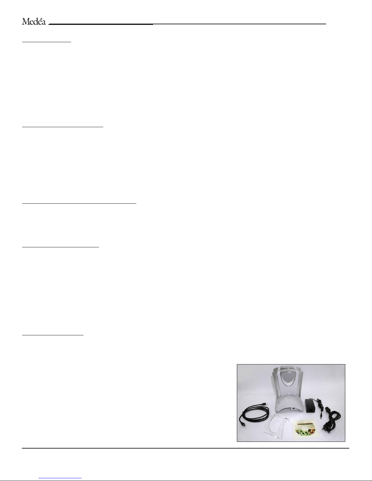
WHAT’S IN THE BOX
Take a moment to ensure that the following items are included in the shipping carton. If anything is missing, please call Medéa at
(818) 880-0303. Please keep the shipping container and packing materials. In the unlikely event that you need to return the product
to us for any reason, you must use the Medéa shipping container. If product is returned damaged due to improper packaging, the
warranty will be void and liability will rest with the user.
Included components:
(2) Disk drive modules
(1) Docking station
(1) External power supply with power cord
(1) 6-pin to 6-pin FireWire cable
(1) Travel stand
(1) Installation CD (includes Mac OSX and Windows synchronization software)
FIREFLY
User’s Guide 7
Page 8
SAFETY PRECAUTIONS
As with all hard drives, FireFly disk drive modules must be handled with care. Follow the precautions listed below to help insure the
integrity of your FireFly system and stored content. Please review the full product warranty located at the end of this document for more
information.
PRECAUTIONS:
-Do not bump, jar, or drop the FireFly disk drive modules.
-Always place the FireFly disk module in the docking station with the proper alignment (see page 9).
-Do not remove any cables or power cords without properly dismounting the drive through the operating system.
-Do not attempt to open the disk module case. Attempting to do so may damage FireFly’s internal components and will void the
warranty.
FIREFLY
User’s Guide 8
Page 9
GETTING STARTED
C
ONNECTING THE DISK DRIVE MODULES TO THE DOCKING STATION
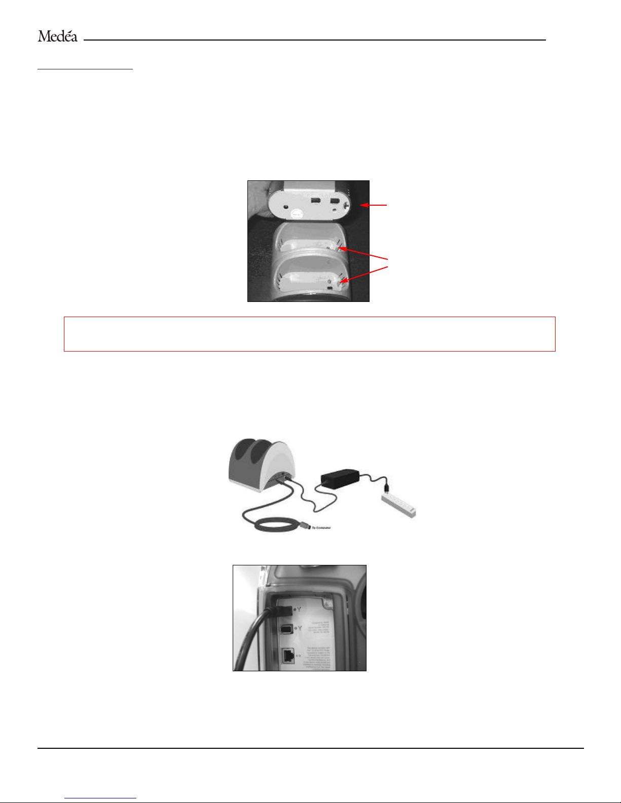
1. Unpack the disk drive modules, docking station, FireWire cable and power supply.
2. Place the disk drive modules into the docking station as shown below.
NOTE: FireFly disk drive modules are keyed to the FireFly docking station. Although the drives can be placed in either slot, they can only be
inserted in one direction. Make sure that the alignment key inside the docking station aligns with the keyhole in the bottom of the disk module.
Tilt the module slightly towards the key as you assert pressure on that side and rock the module down into the docking station.
WARNING: Ensure proper key alignment and use firm even pressure to slide module into docking station. Excessive
force and improper alignment may damage connectors.
CONNECTING POWER AND FIREWIRE CABLE
1. Plug the three-pin female connector of the power cord into the power supply brick. Plug the 3-pin male connector into a standard
110V AC outlet or surge protector. Connect the round power connector into the FireFly docking station as shown below.
2. Plug one end of the FireWire cable into either of the two FireWire ports located on the back of the docking station as shown below.
3. Plug the other end of the FireWire cable to the FireWire port on your workstation as shown below.
Proceed to page 11 to configure FireFly for your operating system.
FIREFLY
Alignment Keyhole
Drive Alignment Keys
User’s Guide 9
Page 10
POWER
MANAGEMENT
FireFly drive modules have a built-in power management feature that not only conserves energy but also extends the life of the
drive. If a FireFly drive module has not been accessed for 10 minutes, the drive will enter Suspend Mode. The Suspend Mode is
indicated by the slow pulsing of the blue power light on and off. If the drive has not been accessed for an additional 20 minutes,
the drive will enter Power Save Mode and the drive will shut down. Any access of the FireFly drive will bring it out of Suspend or
Power Save mode within seconds.
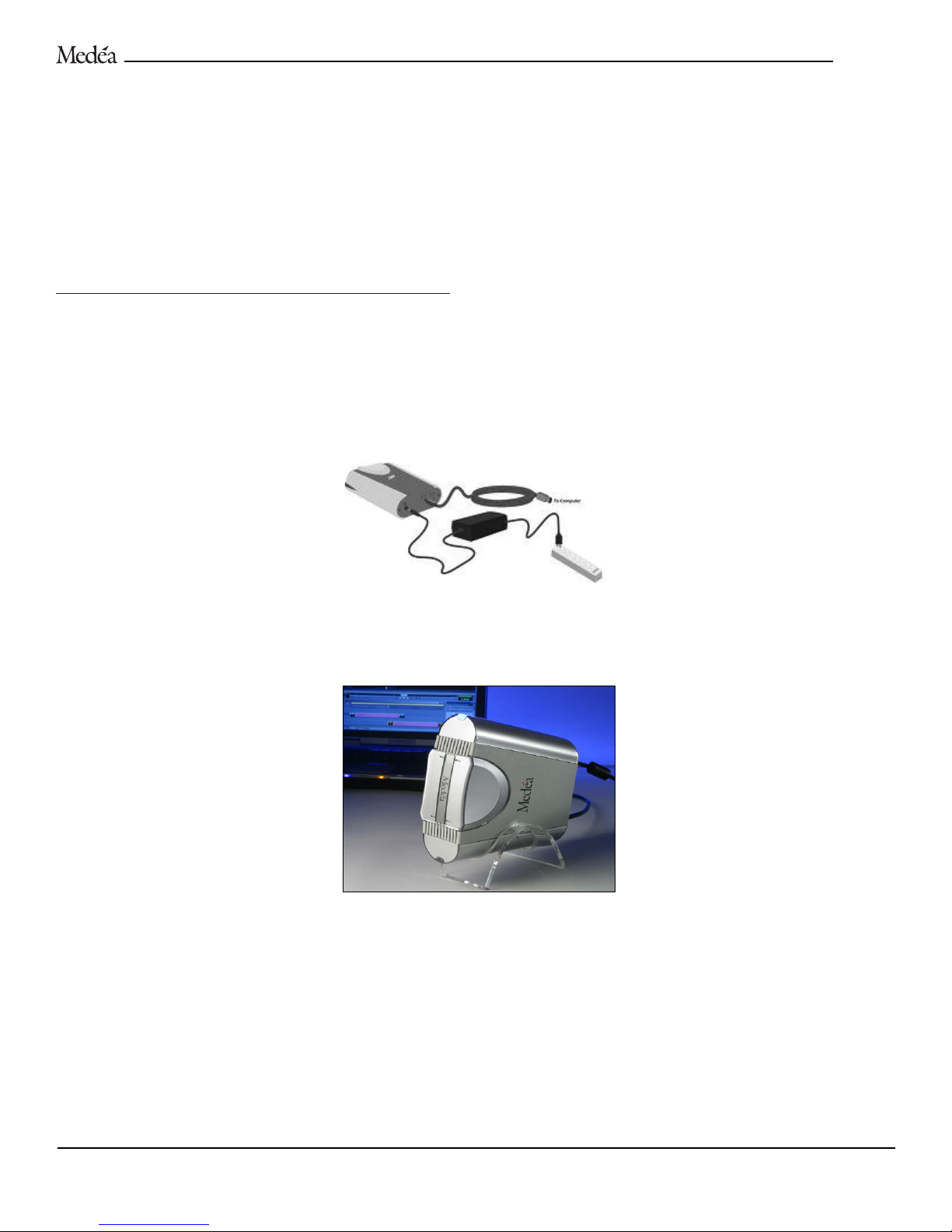
TRAVELING WITH A SINGLE FIREFLY DISK MODULE
If you choose to set up FireFly’s disk modules as independent drives, you can travel with one module while leaving your content secure
on the other module installed in the docking station. Follow the steps below to attach a single FireFly module to your workstation.
1. Plug the three-pin female connector of the power cord into the power supply brick. Plug the 3-pin male connector into a standard
110v AC outlet or surge protector.
2. Connect the round power connector into the FireFly disk drive module. The blue power light will come on to indicate that drive
power has been connected. The amber activity light may also temporarily come on but will extinguish after the drive has
completed self-checks.
3. Place the drive horizontally in the travel stand. The drive module can be oriented in either direction in the stand. With the narrow
edge of the stand forward, the drive will have a slight upward inclination. With the wide edge of the stand forward, the drive will
have a more horizontal position.
4. Plug one end of the FireWire cable to either FireWire port on the FireFly module, and the other end to the FireWire port on your
workstation.
FIREFLY
User’s Guide 10
Page 11
OPERATING SYSTEM CONFIGURATION
Now that you have connected FireFly to your workstation, the system must be initialized for your operating system. FireFly is designed
as a flexible storage solution allowing each user to customize it to their particular needs. FireFly’s removable disk drive modules provide a high level of versatility for use as portable, stationary, striped (RAID 0) or mirrored (RAID 1) storage.
For Windows 2000/XP installations, proceed to page 19.
For Mac OS X installations, see the instructions below.
CONFIGURING FIREFLY FOR MAC OS X (10.2.X) WORKSTATIONS
To initialize a FireFly as independent drives, enabling the modules to operate as a stand-alone FireWire drives, follow the instructions below.
Initializing as independent drives offers most flexibility and enables you to use FireFly with the included synchronization software.
If you wish to stripe (RAID 0), proceed to page 14 or to page 16 for mirroring (RAID 1) FireFly modules.
INITIALIZING AS INDEPENDENT DRIVES – MAC OS X
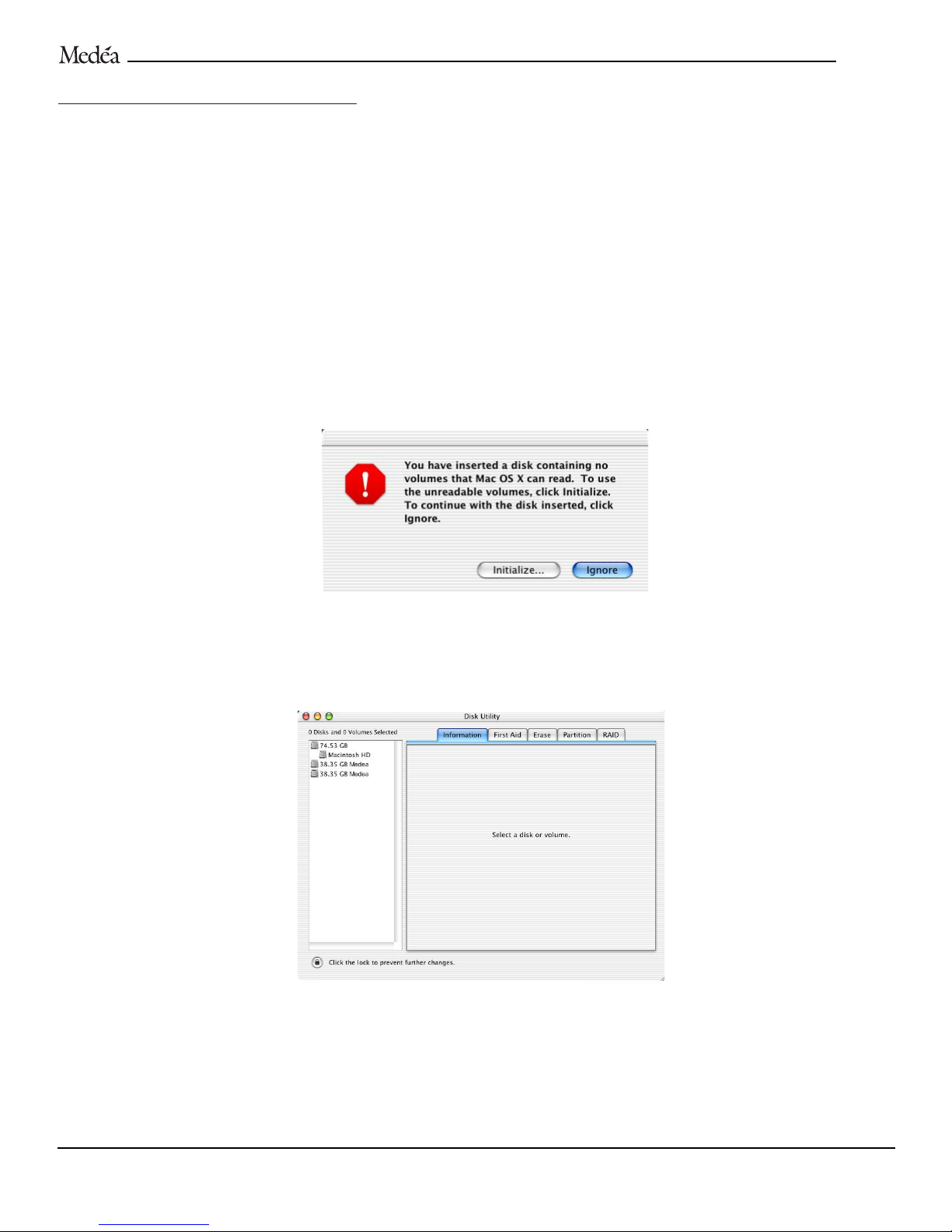
1. Ensure both disk modules are installed in the FireFly Docking Station. Power on FireFly. Power on your Macintosh. The first
time FireFly is connected to your workstation and powered on, an Alert window(s) will appear as shown below. This is normal.
NOTE: If you have both FireFly modules installed in the docking station, two of the above windows will appear. Click Ignore in one window
and then proceed as below. If no window appears, launch the Apple Disk Utility located in the Utilities folder on the Macintosh HD.
2. Select Initialize… to open the Apple Disk Utility. A window like the following will appear. The FireFly disk drive module(s) are
displayed, along with their capacities, in the left-hand column as shown.
3. Select a FireFly disk module by clicking on the entry in the left-hand column as shown on the following page. The disk module
information will be displayed on the right.
FIREFLY
User’s Guide 11
Page 12
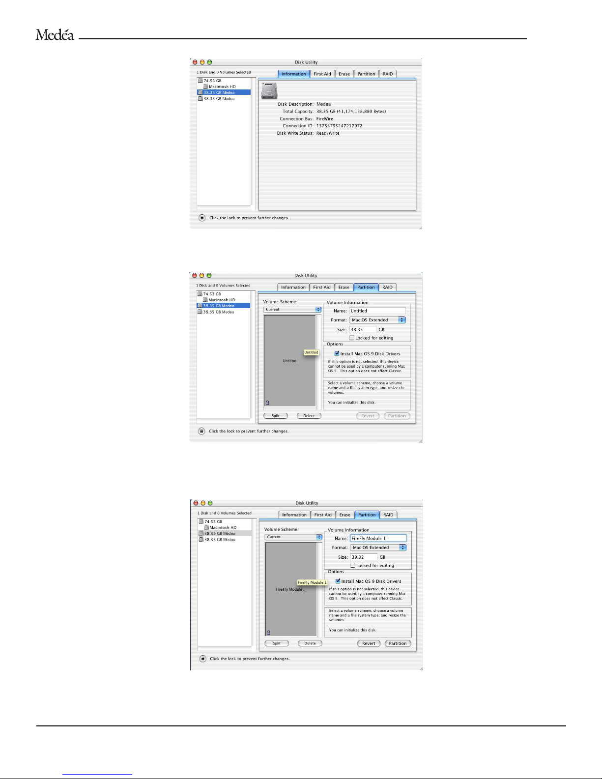
4. Select the Partition tab to view the partition options as shown below.
5. Set the Volume Scheme: to
Current. Enter a volume Name: under Volume Information (in this example – FireFly Module 1), set
format to
Mac OS Extended, and if you intend to use the module on a Mac running OS 9, check the box under Options.
NOTE: Each FireFly disk module can be set up in multiple volumes if desired. Please refer to the Apple documentation for instructions on
setting up multiple volumes on FireFly.
FIREFLY
User’s Guide 12
Page 13
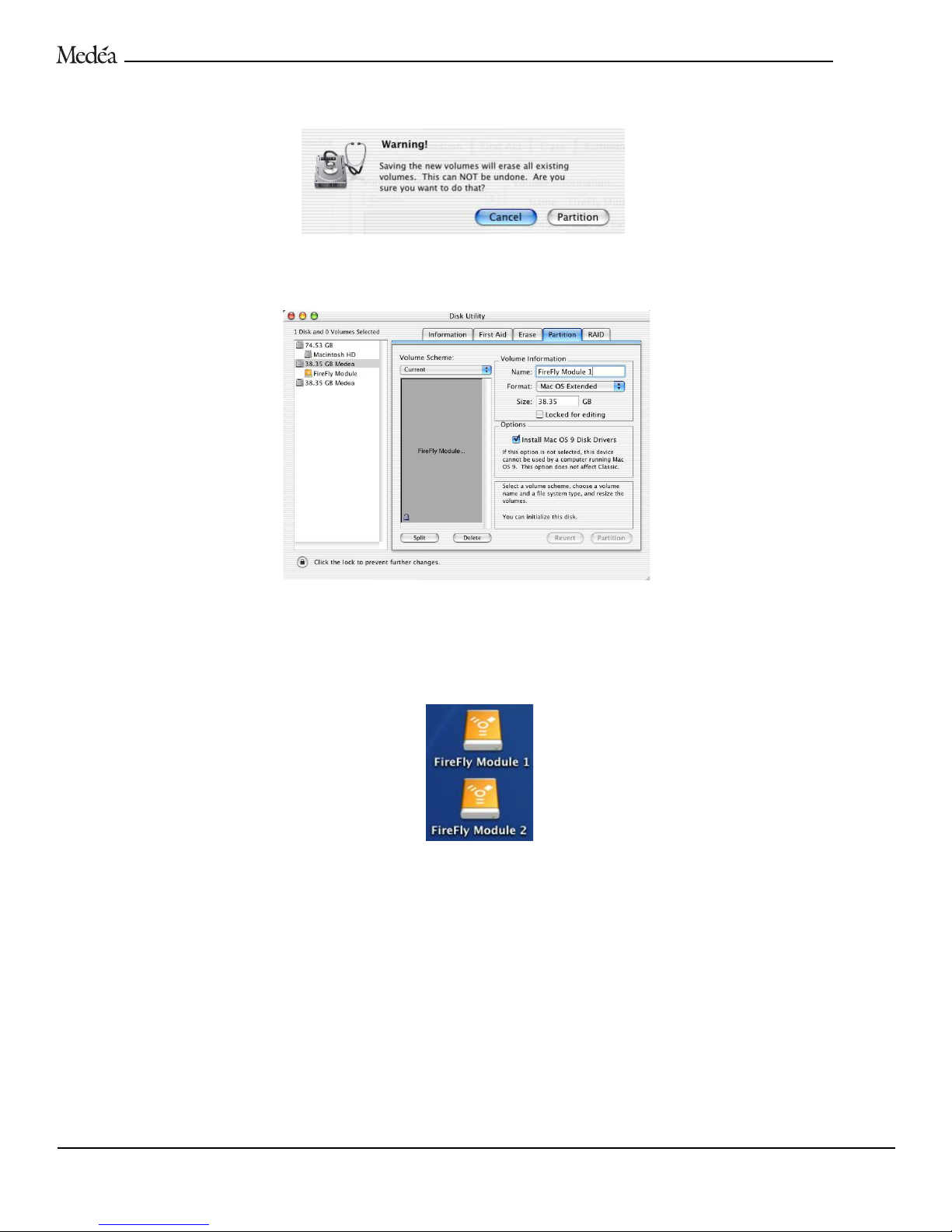
6. Click on the Partition button. The following Warning! window will appear. Click on the Partition button to continue.
7. When partitioning is complete, the FireFly module will be displayed as a FireWire device in the left-hand window as shown below.
8. Repeat the above five steps to initialize the second FireFly disk drive module.
9. Exit the Disk Utility.
10.The FireFly disk drive modules(s) will be displayed as icons on the desktop as shown below.
FIREFLY
User’s Guide 13
Page 14
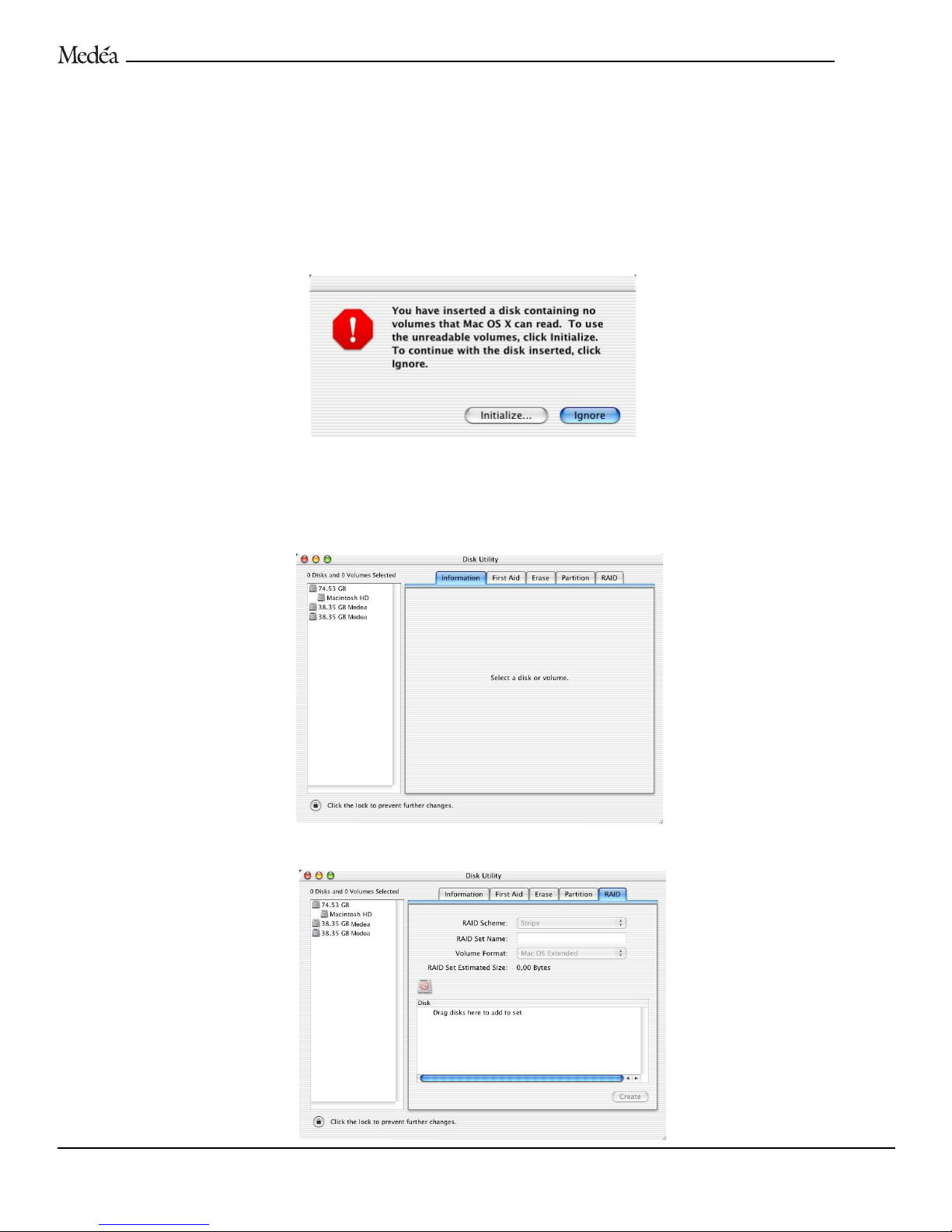
STRIPING
FIREF
LY DRIVE MODULES – MAC OS X
Striping (RAID 0) FireFly disk modules together will create one large volume and the content stored will be automatically distributed
across the two disk drive modules. This configuration provides a higher data transfer rate than that of a single module, but does not
provide data protection. In order to stripe with FireFly, you must have both disk drive modules installed in the docking station before
proceeding.
NOTE: If you stripe or mirror FireFly, the disk modules can be used on another workstation with the same OS, but must stay together as a set.
1. Power on FireFly. Power on your Macintosh. The first time FireFly is connected to your workstation and powered on, an Alert
window(s) will appear as shown below. This is normal.
NOTE: Two of the above windows will appear. Click Ignore in one window and then proceed as below. If no window appears, launch the Apple
Disk Utility located in the Utilities folder on the Macintosh HD.
2. Select Initialize… to open the Apple Disk Utility. A window like the following will appear. The FireFly disk drive module(s) are
displayed, along with their capacities, in the left-hand column as shown.
4. Select the
RAID tab to view the RAID options as shown below.
FIREFLY
User’s Guide 14
Page 15
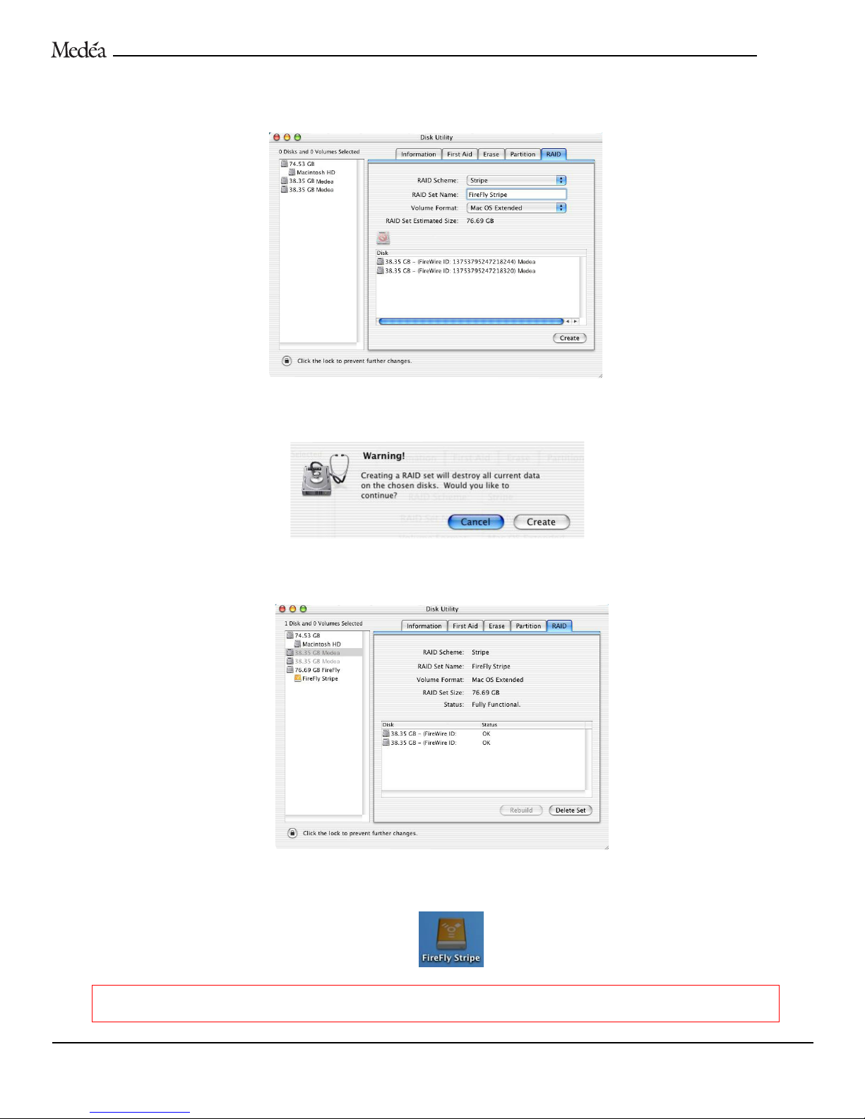
5. Drag each FireFly disk module from the left-hand column to the right area labeled Drag disks here to add to set. Set RAID Scheme:
to
Stripe, enter a RAID Set Name: (in this example FireFly Stripe) and set the Volume Format: to Mac OS Extended as shown below.
6. Click on the
Create button. The following Warning! will appear. Click on the Create button to continue.
7. When complete, the FireFly stripe set will be displayed as a FireWire device in the left-hand window as shown below.
8. Exit the Disk Utility.
9. The FireFly stripe set will be displayed as an icon on the desktop as shown below.
WARNING: Once FireFly is configured as a Striped set, both drive modules must remain installed in the docking station. Removal of
one of the drive modules will violate the striped set and destroy all current data on both disks.
FIREFLY
User’s Guide 15
Page 16
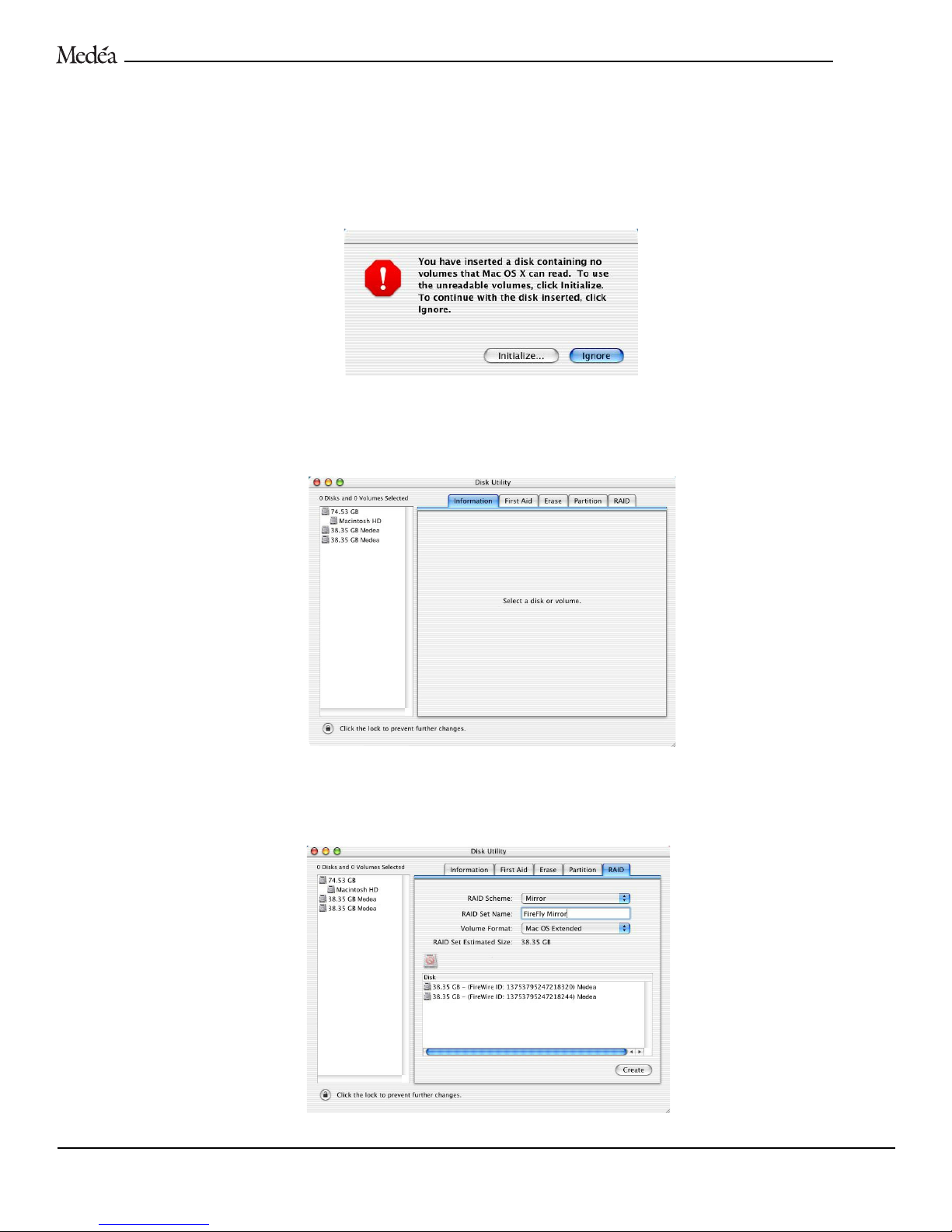
MIRRORING
FIREF
LY DRIVE MODULES – MAC OS X
Mirroring (RAID 1) FireFly modules provides data protection by simultaneously writing the same content to each disk module. If
one module should fail, the content will still be available on the other module. In order to mirror with FireFly, you must have both
disk drive modules installed in the docking station before proceeding.
1. Power on FireFly. Power on your Macintosh. The first time FireFly is connected to your workstation and powered on, an Alert
window(s) will appear as shown below. This is normal.
NOTE: Two of the above windows will appear. Click Ignore in one window and then proceed as below.
2. Select Initialize… to open the Apple Disk Utility. A window like the following will appear. The FireFly disk drive module(s) are
displayed, along with their capacities, in the left-hand column as shown.
3. Select the
RAID tab to view the RAID options as shown below. Drag each FireFly disk module from the left-hand column to the
right area labeled Drag disks here to add to set. Select
Mirror under RAID Scheme:, enter a RAID Set Name: (in this example FireFly
Mirror
) and set the Vo lume Format: to Mac OS Extended as shown below.
FIREFLY
User’s Guide 16
Page 17
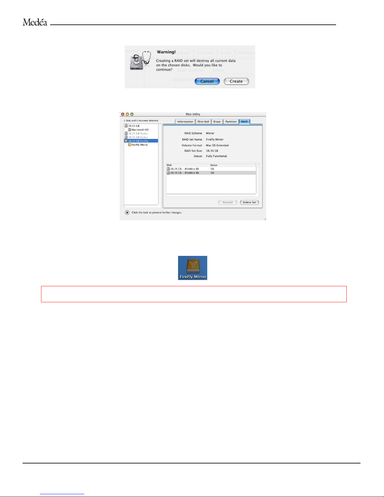
5. Click on the Create button. The following Warning! will appear. Click on the Create button to continue.
6. When complete, the FireFly mirrored set will be displayed as a FireWire device in the left-hand window as shown below.
7. Exit the Disk Utility.
8. The FireFly mirrored set will be displayed as an icon on the desktop as shown below.
WARNING: Once FireFly is configured as a Mirrored set, both drive modules must remain installed in the docking station.
Removal of one of the drive modules will violate the mirrored set and destroy all current data on both disks.
RECOVERING FROM A FIREFLY DISK MODULE FAILURE IN A MIRRORED SET
1. Open the Apple Disk Utility located on the Macintosh HD in
Applications > Utilities.
2. Click the
RAID tab. If an exception has occurred, a dialog box will appear that describes it.
3. If an issue with the disk is indicated, click
Rebuild.
4. If Rebuild does not work, shut down the computer and replace the failed hard disk.
5. Repeat steps 1 and 2.
6. Drag the icon of the new disk on top of that of the removed disk.
7. Click
Rebuild.
FIREFLY
User’s Guide 17
Page 18
REMOVAL AND
R
EPLACEMENT OF FIREFLY DRIVE MODULES - MAC OS X
In order to safely remove or “Put Away” a FireFly Drive in Mac OS X, simply drag the FireFly drive icon to the Trashcan icon located
on the Desktop. Mac OS X automatically spins down the drive on dismount so there is no need for the FireFlyTools application. To
dismount a FireFly drive in Mac OS X, simply drag the FireFly Drive icon to the Trashcan icon located on the Desktop.
NOTE: The Trashcan icon will change when you start to move the disk icon.
MOUNTING A F
IREFLY D
RIVE
1. Make sure the power cord is connected and the drive’s blue power light is on.
2. Connect the FireWire cable to both the FireFly Docking Station and your computer. After a moment, the computer will recognize
that your drive is connected and the drive icon will appear on the Desktop.
If the FireFly drive is powered and connected to the system at startup, the drive will automatically be mounted.
USING THE SYNCHRONIZE! PLUS X SOFTWARE – MAC OS X
Synchronize! Plus X file synchronization software is provided on the enclosed CD. Synchronize! Plus X compliments your FireFly
system by enabling quick and easy synchronization of files/folders between FireFly disk modules. This software allows you to leave
one disk module safe in the docking station while creating content on the fly with the other FireFly module. When you return the
“mobile” module to the docking station, the content can be automatically sync’d between FireFly modules to provide a high level of
data security for your valuable work.
Refer to the Synchronize! Plus X manual on the enclosed CD for details on the use of this software.
NOTE: You must register your FireFly on-line by visiting www.medea.com/register to receive a Synchronize! Plus X serial number.
FIREFLY
User’s Guide 18
Page 19
CONFIGURING
FIREF
LY FOR WINDOWS 2000/XP WORKSTATIONS
In order to initialize FireFly modules as stand-alone FireWire disk drives, follow the instructions below. Initializing as independent drives
offers the most flexibility and enables FireFly to be used with the included synchronization software.
If you are running Windows XP Professional and wish to stripe (RAID 0) FireFly modules, proceed to page 23.
INITIALIZING AS INDEPENDENT DRIVES – WINDOWS 2000/XP
Note: This procedure will create two Basic Disk volumes. Initializing FireFly modules as Basic Disks will enable you to use the modules on any
workstation running MS-DOS or Windows 98se/Me/NT/2000/XP. If you wish to initialize FireFly under Windows 98se/Me, please consult your
Windows documentation.
1. Ensure that both disk modules are installed in the docking station. Power on FireFly. Power on your workstation.
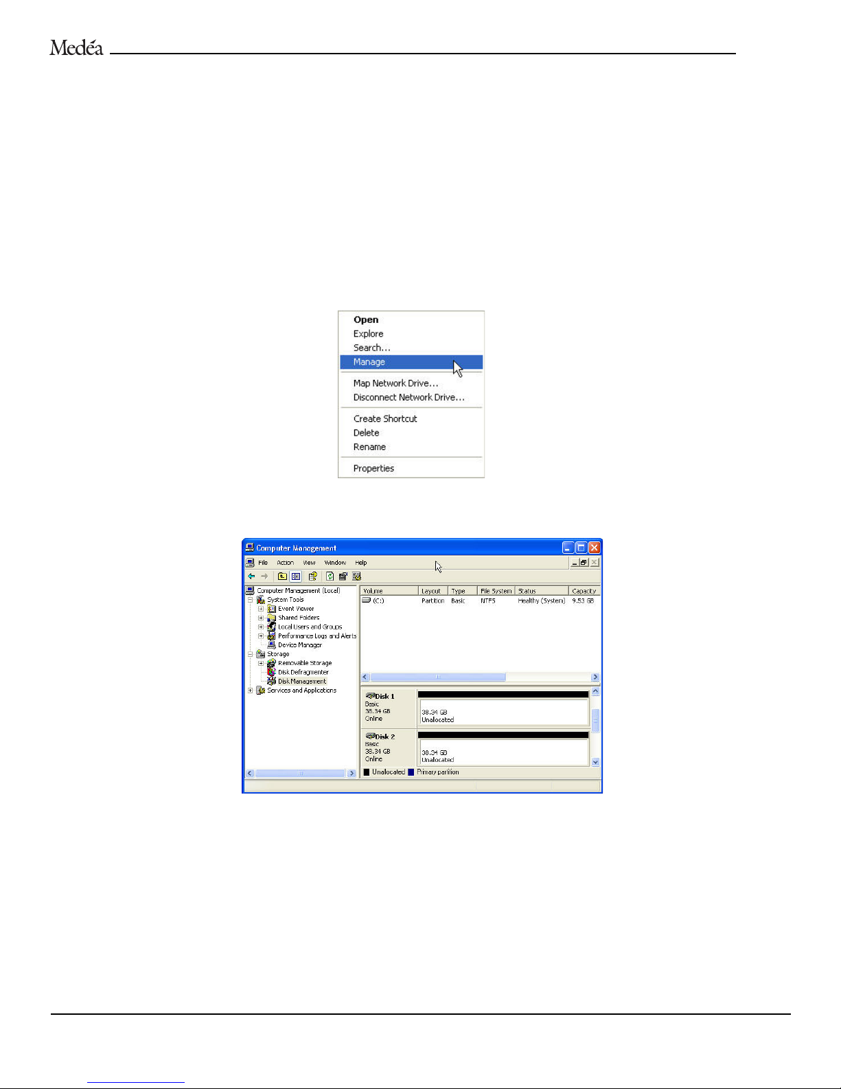
2. Right-click on the
My Computer icon located on the desktop and select Manage from the pull-down menu as shown below.
3. The Computer Management console will appear. Click on
Disk Management in the left-hand panel as shown below. The FireFly
disk modules are identified as Disk 1 and Disk 2 in this example.
4. Right-click on the
Disk 1 entry as shown on the following page and select New Volume… from the pull-down menu.
FIREFLY
User’s Guide 19
Page 20
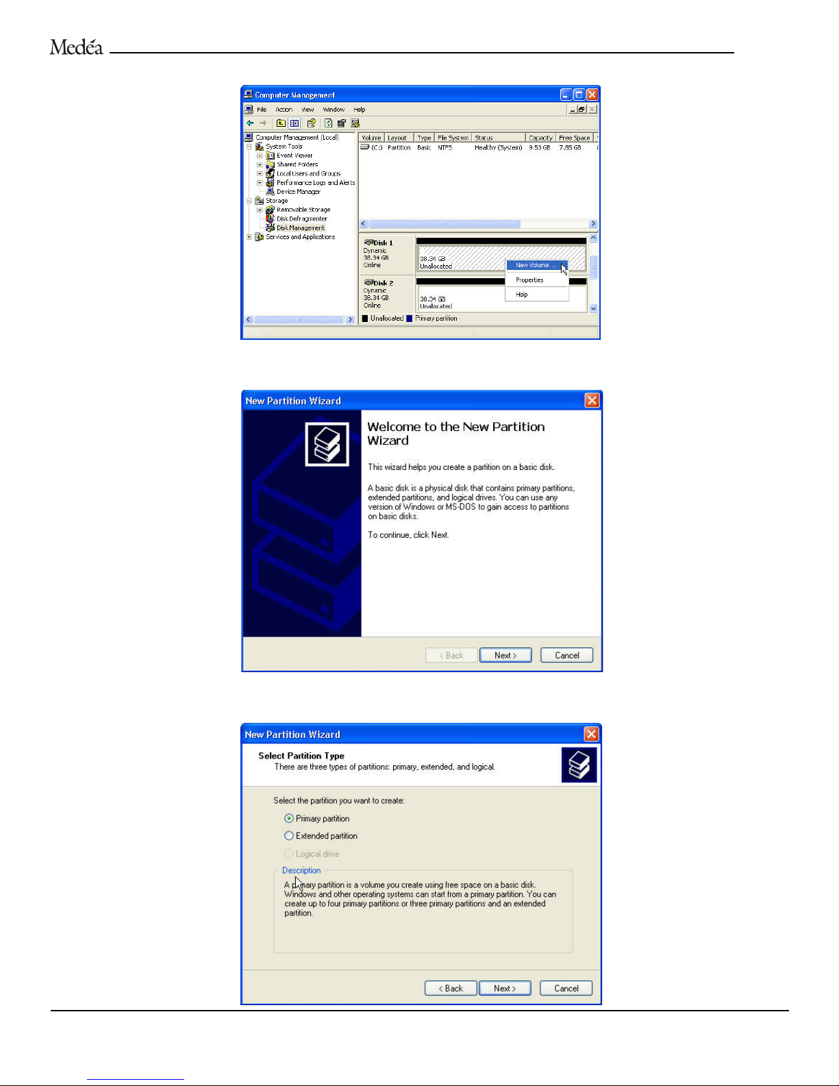
5. The following window will appear. Click the Next button to continue.
6. The following window will appear. Click the
Next button to continue.
FIRE
F
LY
User’s Guide 20
Page 21
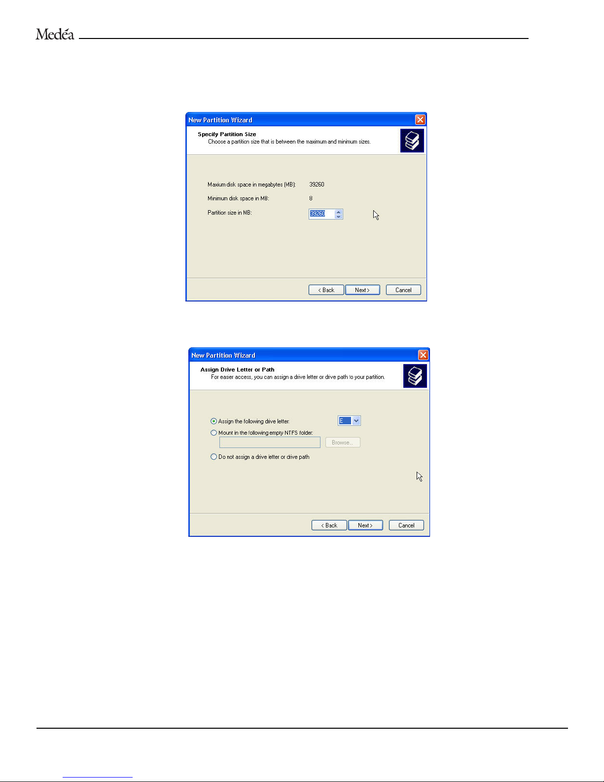
7. The following window will appear. Click the Next button to continue. This will create one large volume (one drive letter) using
all of the available space on the FireFly disk module.
NOTE: Multiple partitions can be created on a FireFly disk module. Consult your Windows documentation for instructions to set up
multiple partitions.
8. The following window will appear. Windows will automatically assign a drive letter (in this example E:) to the FireFly disk module.
Accept this assignment and click the
Next button to continue.
9. The window on the following page will appear. Enter a Volume Label: (In this example
FireFly 1), check the Perform a quick format
box and click the Next button to continue.
FIREFLY
User’s Guide 21
Page 22
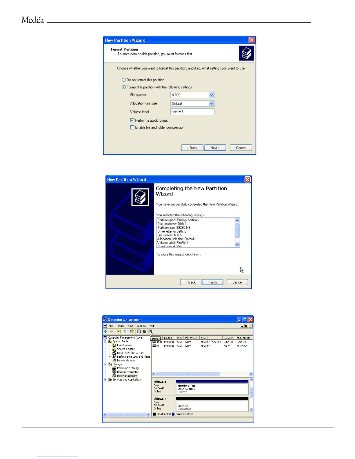
10.The following window will appear. Click the Finish button to continue.
11.Windows will format the volume and then display the following window. Disk 1 is now identified as FireFly 1 (E:).
FIRE
F
LY
User’s Guide 22
Page 23
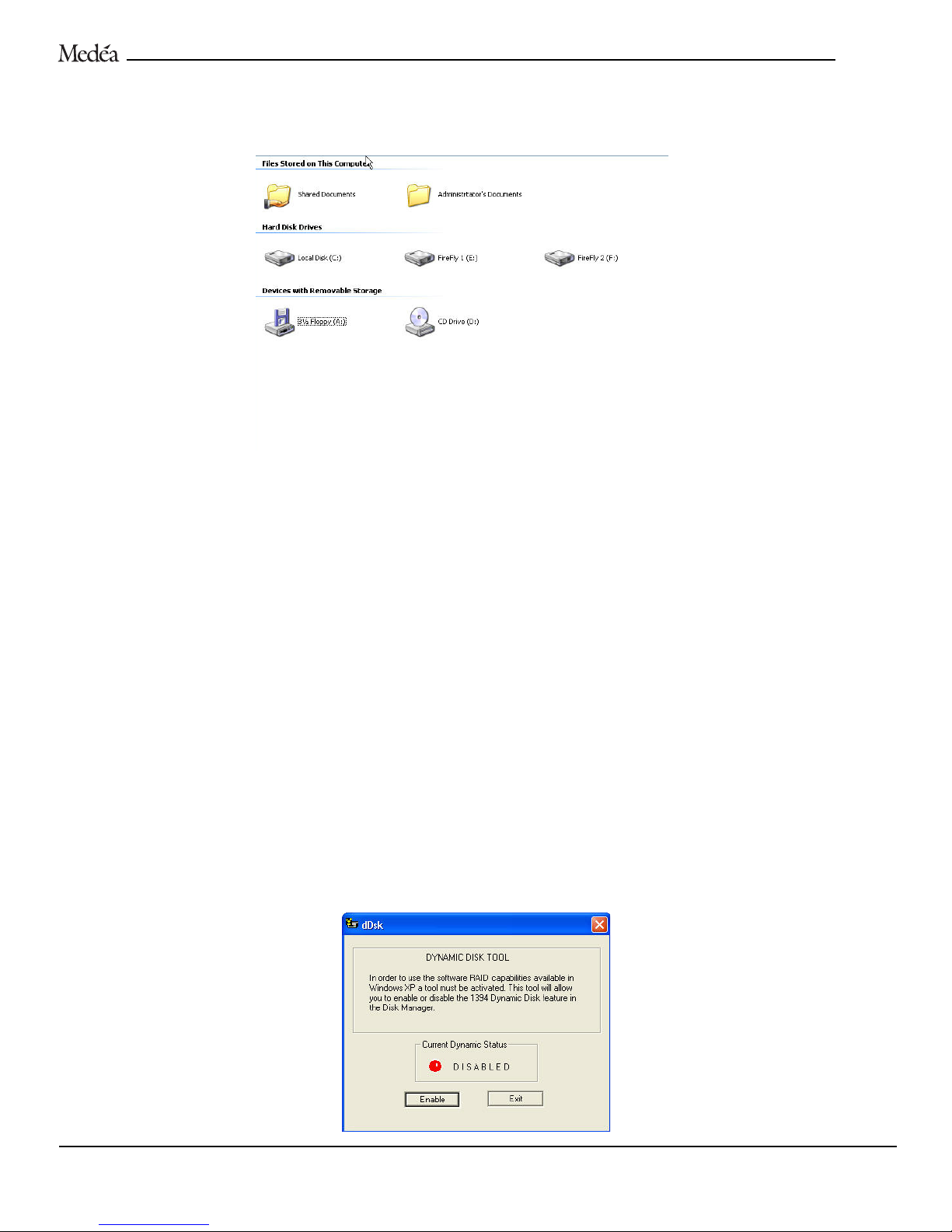
12.Right-click on the Disk 2 entry and select New Volume… from the pull-down menu. Follow steps 5 – 11 above to initialize the
second FireFly disk module. After the initialization process, both FireFly disk modules will show up as independent drives under
My Computer as shown below.
NOTE: During the above initialization process, Windows 2000/XP will default to a setting of “Optimized for Quick Removal” for each
FireFly module. This is the recommended setting for FireFly modules. For more information, consult your Windows documentation.
IMPORTANT! Now that your FireFly system has been initialized, proceed to page 29 for instructions on safely removing the disk
drive modules while your workstation is running.
STRIPING FIREFLY DRIVE MODULES – WINDOWS XP PROFESSIONAL
Striping (RAID 0) FireFly disk modules together will create one large volume and the content stored will be automatically distributed
across the two disk drive modules. This configuration provides higher data transfer rates than that of a single module.
NOTE: If you stripe FireFly, the disk modules can be used on another workstation with the same operating system, but must stay together as
a matched set.
In order to stripe FireFly modules you must:
-Be running the Windows XP Professional operating system.
-Have both disk modules installed in the docking station.
-Install the Dynamic Disk Enabler called dDsk located on the enclosed CD.
INSTALLING DDSK
To install dDsk, run the Setup.exe application located in the FireFly Tools folder on the enclosed CD.
1. Once you have installed FireFly Tools, open dDsk by selecting
Start > Programs > iNDi Drives > dDsk. The following window will
appear.
FIRE
F
LY
User’s Guide 23
Page 24
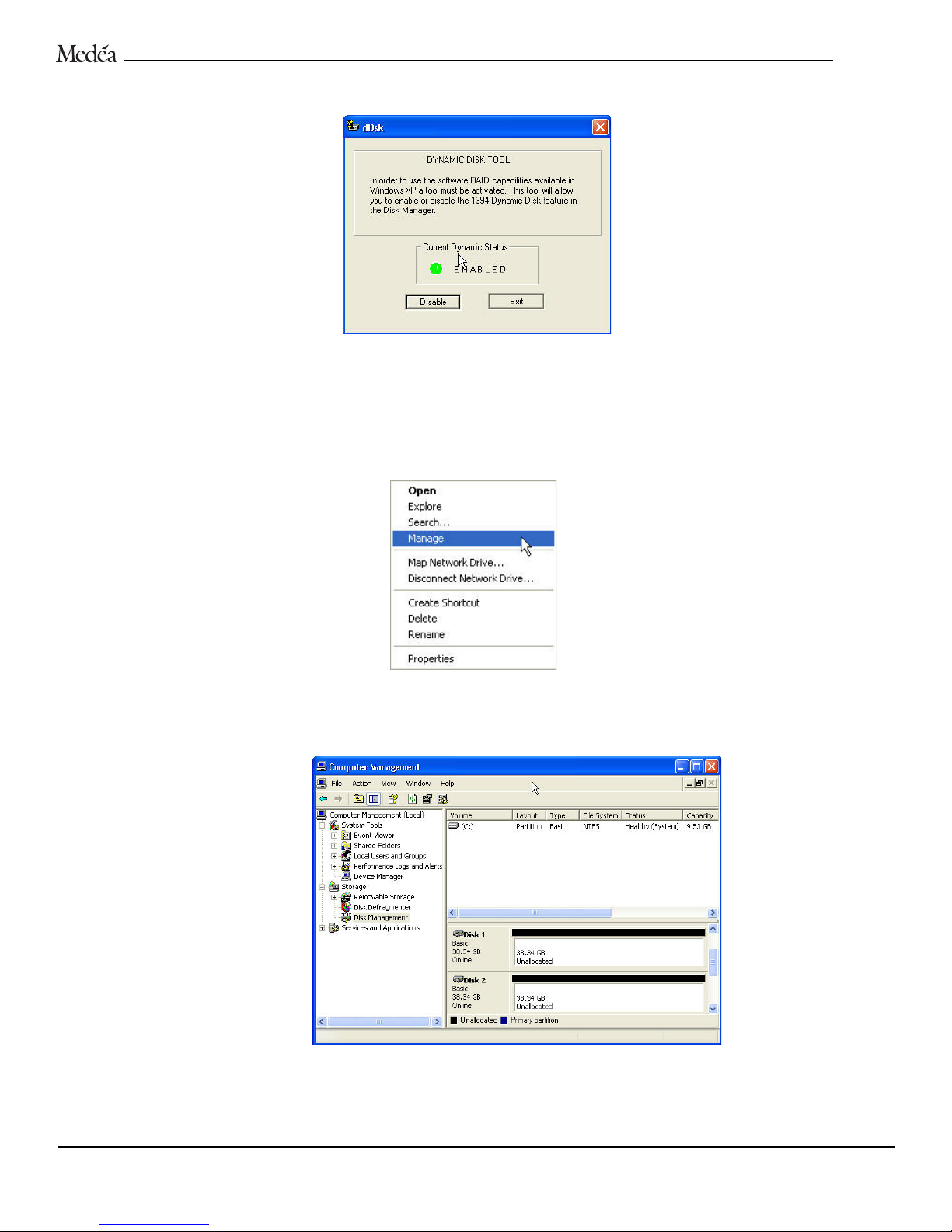
2. Click on the Enable button. The following window will appear indicating that the dDsk has been enabled.
3. Click on the
Exit button.
Now that dDsk has been enabled, you must convert each FireFly disk module to a Dynamic Disk and then stripe the two modules
together using the Computer Management console.
1. Right click on the
My Computer icon located on the desktop and select Manage from the pull-down menu as shown below.
2. The Computer Management console will appear. Click on Disk Management in the left-hand panel as shown below. The FireFly
disk modules are identified as
Disk 1 and Disk 2 in this example.
FIREFLY
User’s Guide 24
Page 25
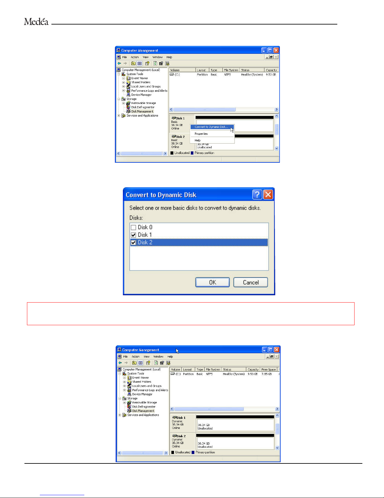
3. Right-click on the box labeled Disk 1 and select Convert to Dynamic Disk… from the pull down menu.
4. The following window will appear. Select
Disk 1 and Disk 2 by checking each box and click the OK button to continue.
WARNING! Be absolutely sure that the disks you check in this step represent the FireFly disk modules before
proceeding. Selecting other disk drives will cause loss of data on those drives.
5. The following window will appear. Note that Disk 1 and Disk 2 are now identified as Dynamic.
FIRE
F
LY
User’s Guide 25
Page 26
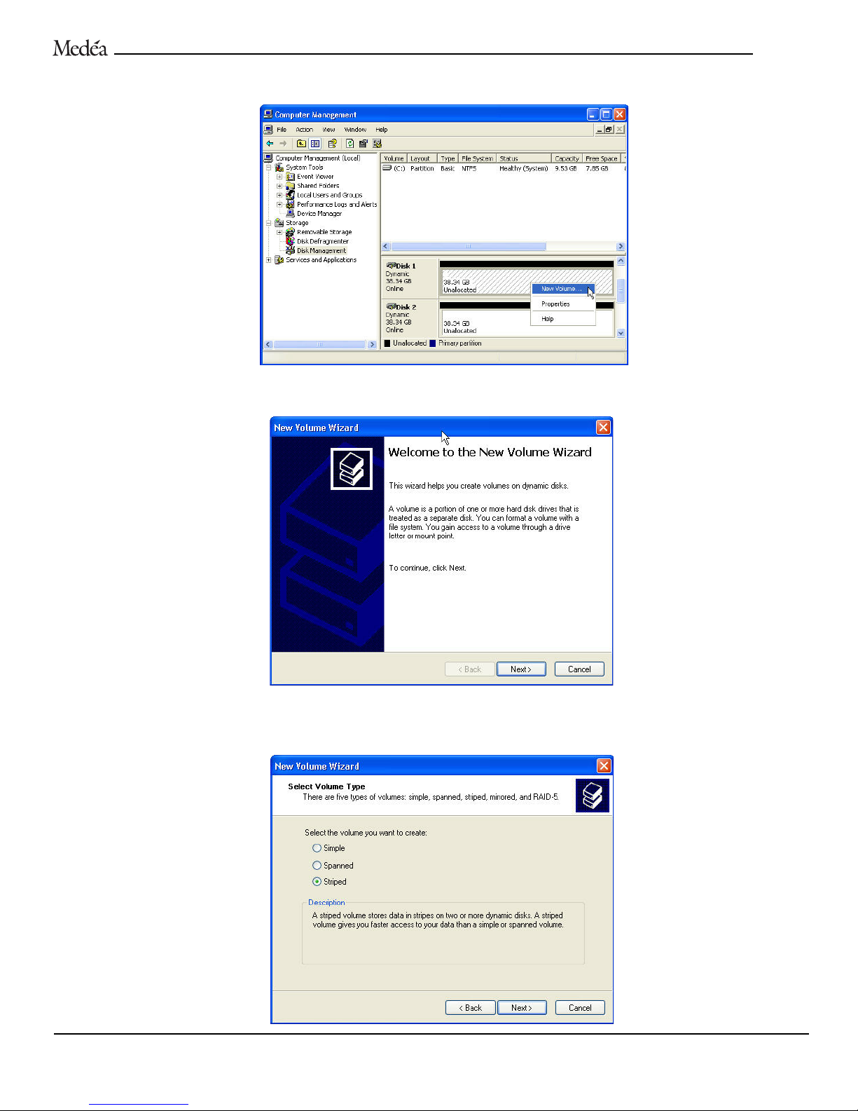
6. Right-click on the Disk 1 entry and select New Volume… as shown below.
7. The New Volume Wizard will appear. Click the
Next button to continue.
8. The following window will appear. Select
Striped by clicking on the radio button as shown below and click on the Next button
to continue.
FIRE
F
LY
User’s Guide 26
Page 27
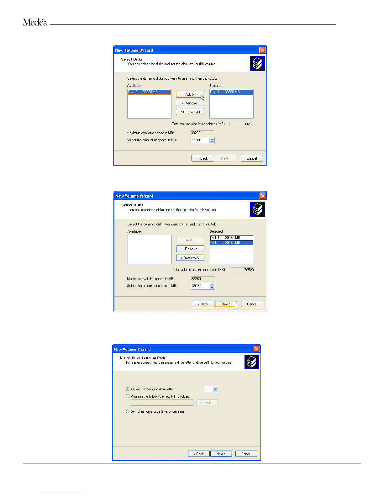
9. The following window will appear. Select Disk 2 in the left-hand panel as shown below and click on the Add button.
10.The following window will appear. Click on the
Next button to continue. This will create a stripe set consisting of one large
volume (one drive letter) utilizing all of the available space on both FireFly disk modules.
NOTE: Multiple partitions can be created with a stripe set. Consult your Windows documentation for instructions to set up multiple partitions.
11.The following window will appear. Windows will automatically assign a drive letter (in this example E:) to the FireFly stripe set.
Accept this assignment and click the
Next button to continue.
FIREFLY
User’s Guide 27
Page 28
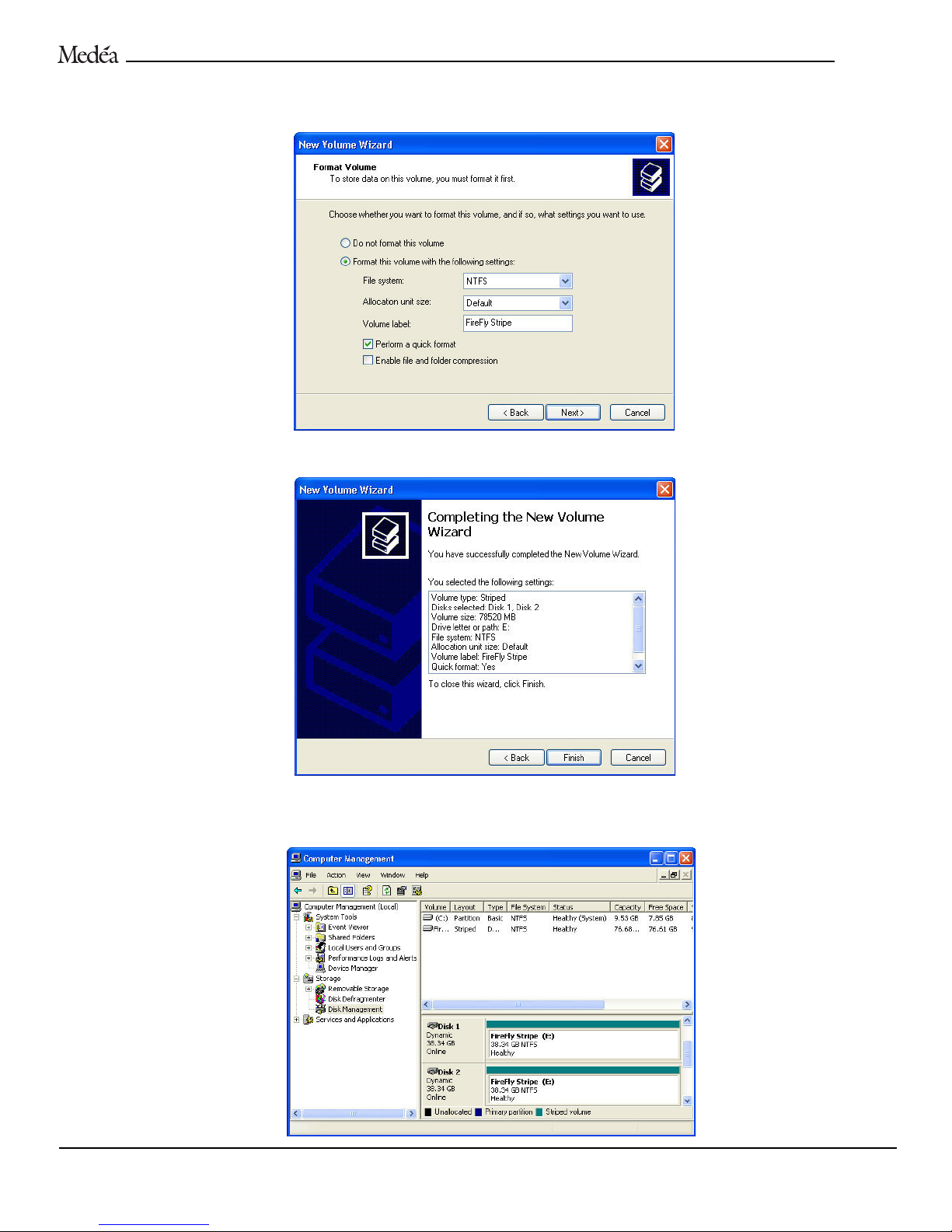
12.The following window will appear. Enter a Volume Label: (In this example FireFly Stripe), check the Perform a quick format box
and click the
Next button to continue.
13.The following window will appear. Click the
Finish button to continue.
14.Windows will format the stripe set and then display the following window. Disk 1 and Disk 2 are now identified as a striped
volume called FireFly Stripe (E:). At this point, you can close the Computer Management window.
F
IREFLY
User’s Guide 28
Page 29
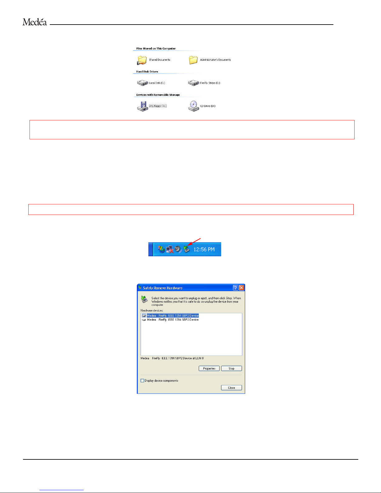
15. The FireFly Stripe set will now show up as a single drive under My Computer.
WARNING: Striped FireFly modules become a matched set and cannot be used independently. Both drives must remain installed in
the docking station. Removal of one of the drive modules will violate the striped set and destroy all current data on both disks.
IMPORTANT: Now that your FireFly system has been initialized, follow the instructions below on safely removing the disk drive
modules while your workstation is running.
P
ROCEDURE TO SAFELY REMOVE A FIREFLY MODULE FROM THE DOCKING STATION – WINDOWS 2000/XP
IMPORTANT: To ensure data integrity, you must always observe the following “unplug” procedure when removing a FireFly disk
module from the docking station.
WARNING: Never attempt to remmove a drive module that is part of a stripe set. Removal will causee all data to be destroyed.
1. Double-click on the Safely Remove Hardware icon located in the system tray next to the clock as shown below.
2. The following window will appear. Select the FireFly module you wish to remove and click on the
Stop button.
FIREFLY
User’s Guide 29
Page 30
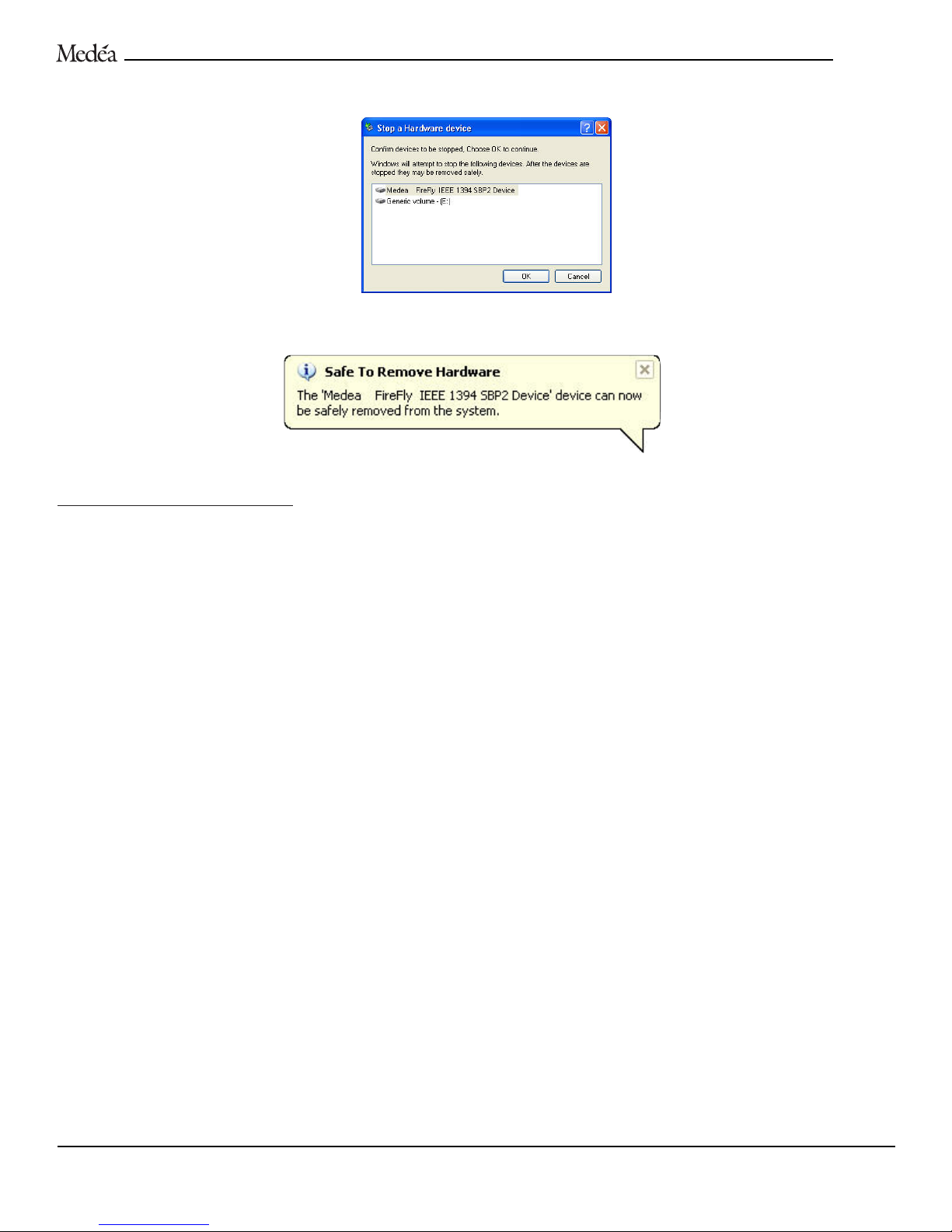
3. The following window will appear. Click the OK button to continue.
4. The following message will be displayed letting you know that it is now safe to remove the FireFly disk module from the docking
station.
Using the Save-N-Sync Software
Save-N-Sync file synchronization software is provided on the enclosed CD. Save-N-Sync compliments your FireFly system by
enabling quick and easy synchronization of files/folders between FireFly disk modules. This software allows you to leave one disk
module safe in the docking station while creating content on the go with the other FireFly module. When you return the “mobile”
module to the docking station, the content can be automatically sync’d between FireFly modules to provide a high level of data
security for your valuable work.
Refer to the Save-N-Sync manual on the enclosed CD for details on the use of this software.
NOTE: You must register your FireFly on-line by visiting www.medea.com/FireFly/register to receive a Save-N-Sync serial number.
Congratulations! You are now ready to use your FireFly system! Happy creating!!
FIRE
F
LY
User’s Guide 30
Page 31
FIREFLY
User’s Guide 31
TECHNICAL SUPPORT
If you encounter any difficulties while installing your FireFly, please contact Medéa
Technical Support via one of the following ways:
Telephone: (818) 880-0303
Fax: (818) 880-6906
E-mail: [email protected]
Internet: http://www.medea.com
Thank you for purchasing a FireFly disk array. If you have any comments or
questions about this manual or the product, please call (818) 880-0303, or send an
email to [email protected].
Page 32
1-YEAR LIMITED WARRANTY
Medéa Corporation (Medéa) warrants to the purchaser of this product that it will be free from defects in material and workmanship for a period of one (1) year from
the date of purchase. If the product should become defective within the warranty period, Medéa, at its option, will repair or replace the product, or refund the purchaser’s price for the product, provided it is delivered at the purchaser’s expense to an authorized Medéa service facility or to Medéa.
Repair or replacement parts or products will be furnished on an exchange basis and will be either new or reconditioned. All replaced parts or products shall
become the property of Medéa. This warranty shall not apply if the product has been damaged by accident, misuse, abuse or as a result of unathorized service or
parts.
Warranty service is available to the purchaser by obtaining a Return Material Authorization number (RMA) and by delivering the product during the warranty period
to an authorized Medéa service facility or to Medéa. The purchaser shall bear all shipping, packing and insurance costs and all other costs, excluding parts and
labor, necessary to effectuate repair, replacement or refund under this warranty. All returned product must be shipped to Medéa in the original shipping container.
For more information on how to obtain warranty service, an RMA number or to acquire shipping materials, contact Medéa at 26707 W. Agoura Road, Calabasas,
CA 91302, (818) 880-0303.
THIS LIMITED WARRANTY DOES NOT EXTEND TO ANY PRODUCT WHICH HAS BEEN DAMAGED AS A RESULT OF ACCIDENT, MISUSE, ABUSE, OR AS A
RESULT OF UNAUTHORIZED SERVICE OR PARTS.
THIS WARRANTY IS IN LIEU OF ALL OTHER EXPRESS WARRANTIES WHICH NOW OR HEREAFTER MIGHT OTHERWISE ARISE WITH RESPECT TO THIS
PRODUCT.
IMPLIED WARRANTIES, INCLUDING THOSE OF MERCHANTABILITY, FITNESS FOR A PARTICULAR PURPOSE, AND NON-INFRINGEMENT SHALL (A) HAVE
NO GREATER DURATION THAN 1 YEAR FROM THE DATE OF PURCHASE, (B) TERMINATE AUTOMATICALLY AT THE EXPIRATION OF SUCH PERIOD AND
(C) TO THE EXTENT PERMITTED BY LAW BE EXCLUDED. IN THE EVENT THIS PRODUCT BECOMES DEFECTIVE DURING THE WARRANTY PERIOD,
THE PURCHASER’S EXCLUSIVE REMEDY SHALL BE REPAIR, REPLACEMENT, OR REFUND AS PROVIDED ABOVE. INCIDENTAL OR CONSEQUENTAL DAMAGES, INCLUDING WITHOUT LIMITATION LOSS OF DATA, ARISING FROM BREACH OF ANY EXPRESS OR IMPLIED WARRANTYARE NOT THE
RESPONSIBILITY OF MEDÉA AND, TO THE EXTENT PERMITTED BY LAW, ARE HEREBY EXCLUDED BOTH FOR PROPERTY DAMAGE, AND TO THE
EXTENT NOT UNCONSCIONABLE, FOR PERSONAL INJURY DAMAGE.
Some states do not allow the exclusion or limitation of incidental or consequential damages for consumer products, and some states do not allow limitations on how
long an implied warranty lasts, so the above limitations or exclusions may not apply to you.
This warranty gives you specific legal rights, and you may also have other rights which vary from state to state.
User’s Guide 32
F
IREFLY
 Loading...