

Page 1

Operation Manual
Infusion Pump MP-60
Please read this “Operation Manual” carefully and follow “Precautions for Use” before
using the MP-60 Infusion Pump.
MEDCAPTAIN MEDICAL TECHNOLOGYCO., LTD.
Page 2

Intellectual Property and Statement
The intellectual property right of this product and its Service Manual belongs to
MEDCAPTAIN MEDICAL TECHNOLOGY CO., LTD. (hereinafter short as MEDCAPTAIN).
©2015-2016 All rights reserved MEDCAPTAIN MEDICAL TECHNOLOGY CO., LTD.
Without prior approval from MEDCAPTAIN in writing, this Service Manual shall not be
photocopied, modified or translated, fully or partially, by any individual or organization.
, MEDCAPTAIN and are registered trademarks or trademarks of
MEDCAPTAIN.
Statements
MEDCAPTAIN reserves the right for final interpretation of this Service Manual.
MEDCAPTAIN reserves the right to modify the contents of this service manual for a more
accurate and effective service quality. The modified contents should be reflected in the newly
published service manual version.
MEDCAPTAIN is responsible for safety, reliability and performance of this equipment only
in the case that:
Use in accordance with the Operation manual.
All disassembly, replacement, test, modification and repair are executed by qualified
persons approved by MEDCAPTAIN.
All replacement parts, supporting accessories and consumables during the
maintenance are provided by MEDCAPTAIN.
Maintenance records for product are reserved.
Version Information
V1.0
Firstly publish
Publish date:2014.2.28
V2.0
Registration change and content modification
Publish date:2014.5.30
V2.1
Interface Modification
Publish date:2016.3.5
Page 3

Intellectual Property and Statement
V2.2
Service interval modification and writing mistake correction
Publish date:2016.7.30
Page 4

After Service
Thank you for using the infusion pump of MEDCAPTAIN MEDICAL TECHNOLOGY CO., LTD.
During the warranty period, we provide free after-sale services except the following causes:
Artificially damaged.
Inappropriate use.
The voltage of supply network exceeds the range.
Irresistible natural disasters.
Replacing or using parts, accessories and consumables without approval of
MEDCAPTAIN.
Other troubles not caused by product itself.
If the warranty period is expired, we couldcontinue to provide charged maintaining service.
If you have any question when using the infusion pump, please contact local distributor or
directly contact us at any time.
The after-sales service contact details of Medcaptain Medical Technology Co., Ltd. are as
follows:
Address: 12th Floor, Baiwang Research Building, No.5158 Shahe West Road, Xili,
Nanshan District, Shenzhen, P.R.China
Telephone:+86-755-26953369
Fax: +86-755-26001651
Postal: 518055
Website: http://www.medcaptain.com
E-mail:[email protected]
MEDCAPTAIN MEDICAL TECHNOLOGY CO., LTD. and all local dealers established
after-sales service agencies, can effectively, timely solutions to your problems.
WARNING:
The device should be operated by clinic medical staffs or under the instruction of special
clinic medical staffs. The operator should have been trained on how to use this product.
Page 5

Contents
1 OVERVIEW .................................................................................................. 1
1.1 INTENDED USE ............................................................................................... 1
1.2 CONTRAINDICATION ........................................................................................ 1
1.3 PRODUCT FEATURES ...................................................................................... 1
2 PRECAUTIONS FOR USE ........................................................................... 3
3 PRODUCT SPECIFICATIONS...................................................................... 8
4 PRODUCT DESCRIPTION ......................................................................... 10
4.1 PRINCIPLE OF OPERATION .............................................................................10
4.2 COMPOSITION OF INFUSION PUMP ..................................................................10
4.3 HANDLE .......................................................................................................13
4.4 DROP SENSOR ..............................................................................................13
4.5 POLE CLAMP ................................................................................................13
4.6 NURSE PAGER ..............................................................................................14
4.7 ACCESSORIES ACCOMPANIED .........................................................................14
4.8 OPTIONAL ACCESSORIES ...............................................................................14
5 PREPARATIONS FOR USE ....................................................................... 15
6 OPERATING INSTRUCTIONS ................................................................... 16
6.1 DISPLAY AND KEYS ........................................................................................16
6.2 START UP .....................................................................................................18
6.3 IV SET INSTALLATION .....................................................................................19
6.4 PURGE .........................................................................................................21
Page 6

Contents
6.5 SETTING THE INFUSION RATE ..........................................................................21
6.6 PUNCTURE ...................................................................................................22
6.7 STARTING INFUSION ......................................................................................22
6.8 CHANGE RATE DURING INFUSION ....................................................................23
6.9 BOLUS .........................................................................................................23
6.10 STOPPING INFUSION ......................................................................................24
6.11 REPLACING OR ADJUSTING IV SET ..................................................................24
6.12 TURNING THE POWER OFF .............................................................................25
7 SETTING THE INFUSION PUMP ............................................................... 26
7.1 INFUSION SET ...............................................................................................26
7.1.1 Infusionmode ............................................................................................... 26
7.1.2 Occlusion Level ........................................................................................... 28
7.1.3 Bolus Mode .................................................................................................. 29
7.1.4 KVO Rate..................................................................................................... 29
7.1.5 Brand ............................................................................................................ 29
7.1.6 Relay set ....................................................................................................... 29
7.1.7 Drip Mode Set .............................................................................................. 29
7.1.8 NearFinished ................................................................................................ 30
7.2 SYSTEM SET .................................................................................................30
7.2.1 Volume Setting ............................................................................................ 30
7.2.2 Display SET ................................................................................................. 30
7.2.3 Internet Set ................................................................................................... 31
7.2.4 Lock screen Set ............................................................................................ 32
7.2.5 Collection Set ............................................................................................... 33
7.2.6 Linkage mode............................................................................................... 33
7.2.7 PressureUnit ................................................................................................. 34
7.2.8 Date&Time set ............................................................................................. 34
7.2.9 Maintenance ................................................................................................. 34
Page 7

Contents
7.3 HISTORY ......................................................................................................35
7.4 PATIENT FILE ................................................................................................36
7.5 USE INTERNAL BATTERY ................................................................................36
7.6 CONNECTING TO THE <INFUSION CENTRAL MONITORING
SYSTEM>(OPTIONAL) ...............................................................................................38
7.7 NURSE PAGER (OPTIONAL) .............................................................................38
7.8 VOICE COMMUNICATION(OPTIONAL) ................................................................38
7.9 CONNECTING A BARCODE SCANNER (OPTIONAL) ..............................................38
7.10 USER-SPECIFIC REQUIREMENTS (OPTIONAL) ...................................................38
7.10.1 Maximum Flow rate ..................................................................................... 38
8 TROUBLESHOOTING ................................................................................ 39
8.1 ALARM .........................................................................................................39
8.2 FAULTS AND TROUBLESHOOTING ....................................................................40
8.3 TROUBLES AND TROUBLE SHOOTING ...............................................................41
9 MAINTENANCE ......................................................................................... 42
9.1 CLEANING, DISINFECTING ..............................................................................42
9.2 PERIODIC MAINTENANCE ...............................................................................42
9.2.1 Checking the Appearance ............................................................................ 42
9.2.2 Checking the Power Cable ........................................................................... 42
9.2.3 Checking the infusion rate ........................................................................... 43
9.2.4 Alarm ........................................................................................................... 43
9.2.5 Electric and mechanical safety..................................................................... 43
9.2.6 Checking the Internal Battery ...................................................................... 43
9.2.7 Replacing the Battery ................................................................................... 44
Page 8

Contents
9.3 MAINTENANCE ..............................................................................................44
9.4 STORAGE .....................................................................................................45
9.5 TRANSPORTATION .........................................................................................45
9.6 ENVIRONMENTAL PROTECTION AND RECOVERY ...............................................45
10 INFUSION ACCURACY CHARACTERISTICS ............................................ 46
10.1 FLOW RATE CHARACTERISTICS ......................................................................46
10.2 OCCLUSION CHARACTERISTICS ......................................................................49
APPENDIX A ELECTRON MAGNETIC COMPATIBILITY (EMC) ........................... 50
APPENDIX B THE DEFAULT FACTORY SETTINGS ............................................ 56
APPENDIX CTOXIC AND HAZARDOUS SUBSTANCES OR ELEMENTS ............ 57
Page 9

Overview
1 Overview
1.1 Intended use
This product is intended for hospitals to infuse liquid at constant-speed or liquid
medicine continuously through the veins of patients.
1.2 Contraindication
None
1.3 Product Features
MEDCAPTAIN MP-60 is a micro-continuous infusion pump. It ensures constant infusion
speed and accurate dosing volume during longtime infusion.
This infusion pump is used for continuous and micro-volume infusion of liquid or liquid
medicine of little volume and high concentration, including, but are not limited to the
infusion of chemotherapeutic agents, cardiovascular drugs, antineoplastic, oxytocic,
anticoagulant, anesthetic agents.
All current disposable IV sets conform to the standard are supportable.
New IV set conform to the standard can be customized.
Providing eleven occlusion levels and displaying pressure status of the tube.
Maximum infusion rate can be set to 1200mL/h.
Calibration functions for infusion accuracy is available.
Safety design by monitoring infusion states.
Multiple modes of infusion.
Configure with multi-channel infusion workstation, realizing relay infusion function.
WIFI module could be connected to the ICMS to monitor the infusion status.
Nurse call function.
Voice Communication function.
Touchscreen, providing quick and convenient man-machine interface.
Display night mode, reducing light interference to patients and environment.
Connection to barcode scanner function.
Three types of power supply: AC power supply, DC power supply, and internal lithium
battery are available. The lithium battery can power the infusion pump for no less
than 5 hours (at 25ml/h rate).
Double CPU and redundancy design for key units.
Two-way alarm for monitoring the main control circuit and motor drive circuit
1 / 57
Page 10

Overview
Independent motor driving CPU and motor subdivided drive chip design.
Setting and giving automatic prompt of maintenance interval.
Modular installation design enables multi-channel pumps among pumps.
Note:
Handle, pole clamp, barcode scanner, WIFI communication module, voice
communication, nurse call and relay infusion function are optional, dependingon the
user’s need.
2 / 57
Page 11

Precautions For Use
2 Precautions for Use
In this manual, precautions are classified into warning and caution according to the
importance. The meanings are as follows:
WARNING:
The information is about safety and efficiency. Operation against the warning may cause
injuries.
CAUTION:
The information is about guiding suggestions. Operation against the caution may affect
normal use of the product. Read carefully the warnings and cautions in this manual.
WARNING
The infusion pump must be operated by clinical professionals.
The infusion pump cannot be used for blood transfusion.
Prior to use, please check the status of the pump, power cord and other related
accessories to ensure the device could be used normally and safely
Pay extra attention to kinks of the infusion line when it is used for low-infusion. The
smaller the set infusion rate becomes, the longer it takes from the occurrence of
occlusion to its detection, which may suspend the infusion for a long time.
To avoid the risk of fire or explosion, do not use the infusion pump in a flammable or
oxygenated environment.
The altitude difference between the pump and heart position of the patient should not
be larger than 100cm. Smaller difference of the altitude will increase the accuracy of
the pressure sensor’s result.
In the event of tube twisting, filter condensation or intubation occlusion during infusion,
the internal pressure of the infusion tube will increase. Once the causes for occlusion
are removed, too much infusion liquid may be infused into the patient. Therefore,
proper actions should be taken. For example, clamp the infusion tube before
removing the occlusion causes.
To guarantee the infusion safety and alarming function, it is recommended that you
use the IV sets specified by the manufacturer only..
Only the IV set, tube, infusion needle and other medical parts complying with the local
regulations can be used on the infusion pump. Contact your local distributor for more
information.
Operations against the requirements, procedures, warnings and cautions provided in
3 / 57
Page 12

Precautions For Use
this manual may cause infusion failure, inadequate, over dosing, or other potential
risks.
It is recommended to install the drop sensor and open the drop monitoring function. A
long time extrusion without moving or replacing the tube may cause an inadequate
infusion.
There should be a regular monitoring by clinical professionals to observe the clinical
situation and infusion pump working conditionwhen using the device,
The power cord or other affiliated lines should be kept properly to avoid any risk of
twining on patient or electrical disturbance.
High-frequency surgical equipment, mobile phone, wireless device and defibrillator
may have interference on the infusion pump. Keep away from such devices while
operating.
To avoid the risk of electric shock, this equipment must only be connected to a supply
mains with protective earth.
If the pump and its related accessories are reaching over the life time, they must be
crapped and disposed in accordance with the local laws or hospital ordinances.
Please contact your local representative for further details.
Do not modify this equipment without authorization of the manufacturer.
When operating the pump or checking the pump's alarm system, the operator shall
be in front of the device, no farther than 1 meter.
There is no patient circuit in this device. The output of the equipment is not
allowed to be accessible to patient.
The operator shall not touch MP-60 and the patient simultaneously.
CAUTION:
The infusion set is treated as the applied part of the pump.
Check the setting values on the prescription and infusion pump.The infusion can be
started when both values are equal.
In order to prevent extra infusion, close the rolling clamp of the IV sets before
separating the IV sets from pump.
Follow the tube replacement alarm on the display interface, replace the IV sets or
move the IV sets tubing more than 10cm, to keep the infusion accuracy continuously.
Ensure that the infusion pump has been fixed tightly on the stand and the stand is
stable. Prevent the pump from collision, dropping mechanical vibration or other
impact of external forces to avoid damage on the pump.
4 / 57
Page 13

Precautions For Use
Before pressing the [START] key, check if the infusion speed is correct, especially the
position of the decimal point.
Do not operate on the display with sharp objects. Otherwise, the display may be
damaged.
Occlusion alarm may occur when high-viscosity liquid is infused at high speed
through a thin intravenous needle. Increase the occlusion level or decrease the
infusion speed.
The drop sensor detects drops, but not the flow rate. If the liquid in the drop chamber
keeps dripping into continuous liquid flow, the drop signal cannot be detected.
Infusion pump should be placed without the reach of patients and other irrelevant
personnel.
Avoid direct sunlight, high temperature and high humidity.
Do not disinfect the infusion pump by using high-pressure steam sterilization method.
Before using the internal battery, check the battery to ensure that sufficient power is
available. Recharge, if required.
Ensure that the infusion pump always has a battery installed during operation.
Otherwise, the system may stop without issuing an alarm when external power is
interrupted due to power failure or a short circuit, causing an unsafe condition.
If the infusion pump cannot work as described in this manual for unknown reasons,
stop it and report the details (including IV set, infusion flow, serial number of infusion
pump, and type of infusion liquid) to your local distributor or our customer service
department.
Do not operate on the screen using sharp objects. It may damage the screen.
Do not disassemble or reconstruct the infusion pump without authorization.
Liquid intrusion into the AC power socket, USB or nurse call socket may cause
short-circuiting. While connecting the power cable, check if the connecting parts are
dry. If liquid spills on the infusion pump, clean the pump with a dry wiper. Use after
the service engineer checking.
The maximum temperature at the applied part of the pump may reach 41.1℃, when
running continuously under the highest environment temperate at the highest infusion
rate.
Before use, carefully check if the occlusion pressure test function of the infusion
pump is normal .The Maximum infusion pressure at the end of the infusion tube
generated by the pump may be up to 3500mmHg under the condition of
5 / 57
Page 14

Precautions For Use
occlusionwhen sensor failed.
The delay time between the onset of the alarm condition and the representation of the
alarm is no longer than 150ms.
6 / 57
Page 15
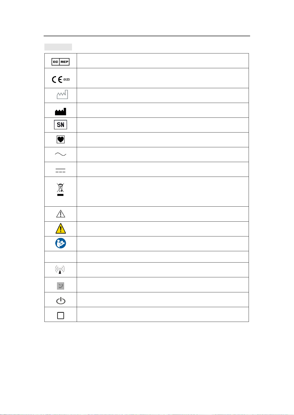
Precautions For Use
Authorized Representative in the European Community
CE Mark: conforms to essential requirements of the Medical
Device Directive 93/42/EEC.
Date of manufacture.
Manufacturer
Specifies serial number
TYPE CF APPLIED PART
Alternating current
Direct current
DISPOSAL: Do not dispose this product as unsorted municipal
waste. Collection of such waste separately for special treatment
is necessary.
CAUTION! Read the accompanying document.
General warning sign
Refer to instruction manual / booklet
IPX2
Level of protection from liquid intrusion
Interference may occur near the devices with below sign.
Nurse pager
ON/OFF
HOME
Symbols
7 / 57
Page 16

Product Specifications
Product name
Infusion pump
Model
MP-60
Power supply
AC power supply:
AC 100-240V,50/60 Hz, power consumption 45 VA
External DC power supply: DC 12 V 1A
Internal battery: lithium battery 11.1 V 1500 mAh
Battery model: 154457
Time of battery continuous use: no less than 5 hours (for infusion at 25
mL/h rate with a new battery)
Fuse
T1.6AL 250VAC
Compatible IV sets
All disposable IV sets conform to the standard
Infusion mode
Rate, Time, Weight, Sequence, Relay, Drip Mode
Infusion setting
range
0.1-1200.0mL/h or(0.03-400d/min)
See the least increment in chart 6-3
VTBI setting range
0.1 - 99.99(Least increment 0.01)
100 - 999.9(Least increment 0.1)
1000 - 9999(Least increment 1)
Total volume
display
0-99999.99ml
Accuracy
±5%
Purge operation
1200.0ml/h
Bolus operation
0.1~1200.0ml/h
Automatically calculate the bolus rate by bolus amount, cannot lower
than the current rate.
KVO rate
0.1-5.0mL/h
Air-bubble sensor
Sensitivity: detect air-bubble ≥
Occlusion level
300mmHg~900mmHg,3 levels are available
Alarm
Near Finished, Finished, OCCL, Low Battery, Battery Empty, No
Battery, No Power Supply, The Pump Door Open, Air Bubble , No Drip
Sensor, No Drips, Drips Abnormal, Reminder Alarm , Relay Index
Duplicate, Infusion Start Fail , Standby Time Expired
Special function
Repeat alarming:If there is still alarm after mute alarm sound, it will
3 Product Specifications
8 / 57
Page 17

Product Specifications
alarm again in 2 minutes
Event recording: Can store and playback 2000 events maximum
Sound volume: 11 levels are available
Power supply switching: When AC/DC power supply is cut off ,the
infusion automatically switch to internal battery supply
Barcode scanning: Input the patient information by barcode canning
WIFI function
Connect infusion workstation, nurse pager, voice communication
and infusion pump information network
Operating
conditions
Temperature: 5℃ to 40℃ Humidity:15% to 95% RH
Pressure altitude: 70.0kPa-106.0kPa
Storage conditions
Temperature: -20℃ to +55℃ Humidity: 10% to 93% RH
Pressure altitude:22.0kPa-107.4kPa
Operation Mode
Continuous operation
Classification
1. Class I / Internally powered equipment;
2. Type CF applied part;
3. IPX2;
4. No sterilization requirement for pump
5. Not category AP / APG equipment;
6. Mode of operation: continuous
Dimensions
202(W) ×74(H) ×133(D)mm
Weight
About 1.6 kg (including battery)
Service Life
10 years
Main safety
standards
IEC60601-1 Medical electrical equipment - Part 1: General
requirements for basic safety and essential performance
IEC60601-2-24 Medical electrical equipment –Part 2-24: Particular
requirements for the safety of infusion pumps and controllers
IEC60601-1-8 Medical electrical equipment -- Part 1-8: General
requirements for basic safety and essential performance -- Collateral
standard: General requirements, tests and guidance for alarm systems
in medical electrical equipment and medical electrical systems
IEC60601-1-2 Medical electrical equipment - Part 1-2: General
requirements for basic safety - Collateral standard: Electromagnetic
compatibility requirements and tests
9 / 57
Page 18
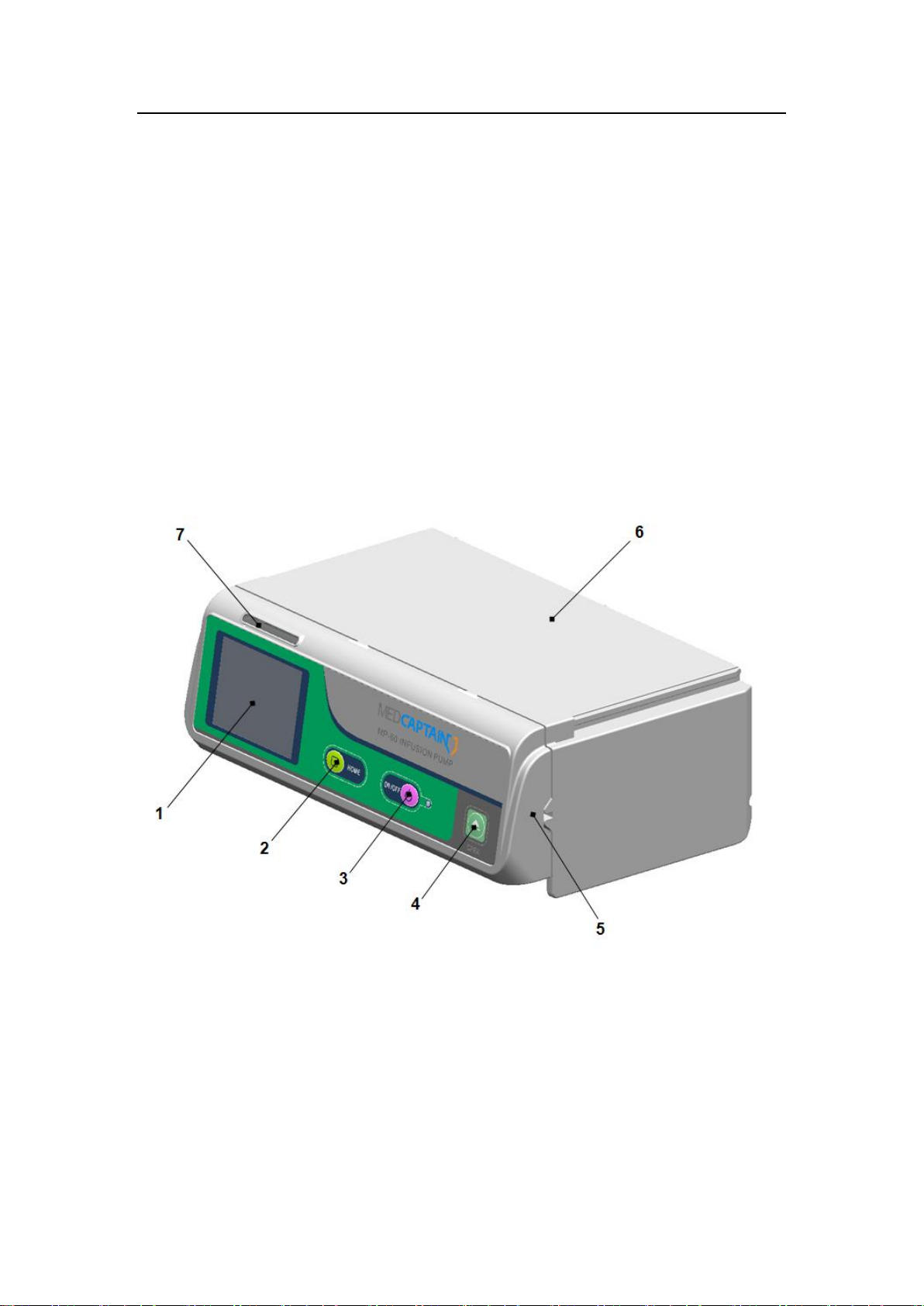
Product Description
1 –Touchscreen
2 – [HOME]key
3 – [ON/OFF]key
4 –[OPEN]key
5 –pump door
6 –Shell
7 –Alarm indicator
4 Product Description
4.1 Principle of Operation
The MP-60 infusion pump mainly consists of pump shell, display screenand operating
system, monitoring system, alarm system, motor drive system, tubing peristaltic module,
power supply system, drop sensor, WIFI communication module (optional), handle
(optional) and pole clamp (optional).
The infusion pump adopts the dual processor structure, controls the motor precisely,
drives the peristaltic sheet to infuse through the mechanical drive device, monitors the
sensors and infusion process, and provides sound and light alarms.
4.2 Composition of Infusion Pump
10 / 57
Page 19
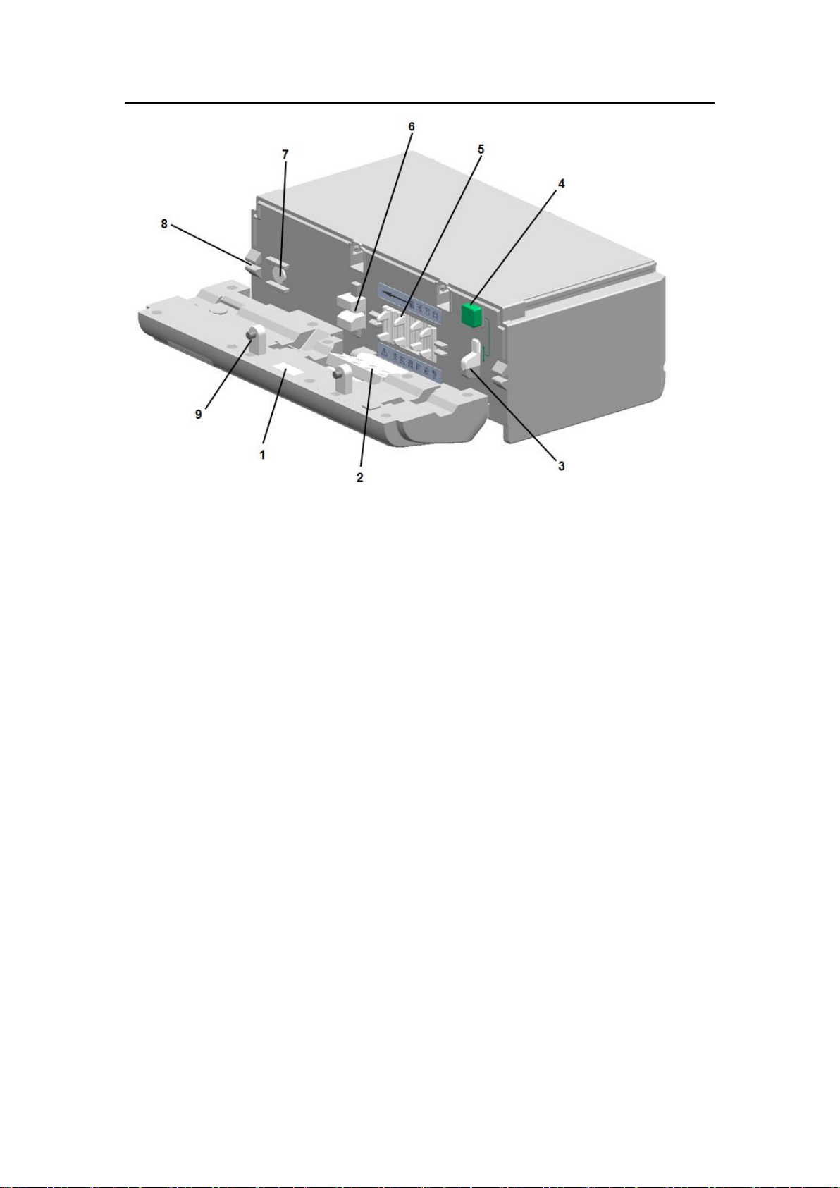
Product Description
1 –Lighting lamp
2 – Depressor
3 – Anti-free-flow clamp
4–Anti-free-flow clamp button
5 – Peristaltic pump plate
6 – Air bubble sensor
7 –Pressure sensor
8 –Infusion tube slit
9 – Catch
Lighting lamp. To provide lighting in a dim environment, so as to install and check the
infusion tube
Depressor and peristaltic plate. Driven by the step motor, press and move the tube to
realize liquid flow
Anti-free-flow clamp. Stop liquid flow and infusion backwards after the pump door
opens
Anti-free-flow clamp button. Press the button and the clamp will automatically open or
close.
Pressure sensor and bubble sensor. Sensors monitor occlusion pressure and air
bubble inside the infusion tube.
Infusion tube slit. At sides of pump to guide the infusion tube in a line behind the
pump door.
Catch. The two catches are used to close the pump door.
11 / 57
Page 20
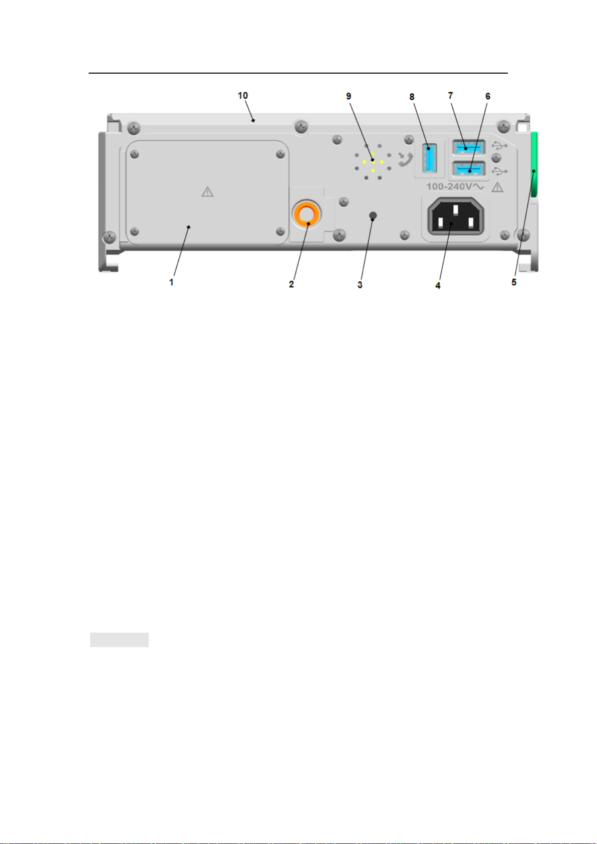
Product Description
1 –Battery cover
2 –Threaded hole
3 –Auxiliary alarm
4 – AC power inlet
5 –Combination clamp
6 –External inlet 1
7 –External inlet 2
8 –External inlet 3
9 –Buzzer
10 – Shell
Battery chamber. Replaceable battery inside the chamber.
Threaded hole. To fix the pole clamp, then fix the pump to the IV pole via the pole
clamp.
Auxiliary alarm. Audible alarm sounds when product functions abnormally.
Buzzer. To alarm in high, medium or low level during infusion and enable voice
conversation.
AC power inlet. To connect the external AC power source.
External inlets 1, 2 and 3. The three inlets share the same signal and can be
connected to 3 external devices at the same time. The external devices include drop
sensor, barcode scanner, external DC power cord. The external inlet 1 and 2 could
be used as the interface for the local WLAN.
CAUTION:
Only the accessories or devices specified by the manufacturer allowed to be
connected to the Pump. Otherwise may cause electrical shock. See Table4-1.
The person who connects the devices and accessories to each other or who uses the
devices and accessories is responsible and liable for installation and operation that
complies with IEC/EN 60601-1-1 or clause 16 of IEC 60601-1.
The plug is used as disconnect to the mains supply, do not position the pump so that
12 / 57
Page 21
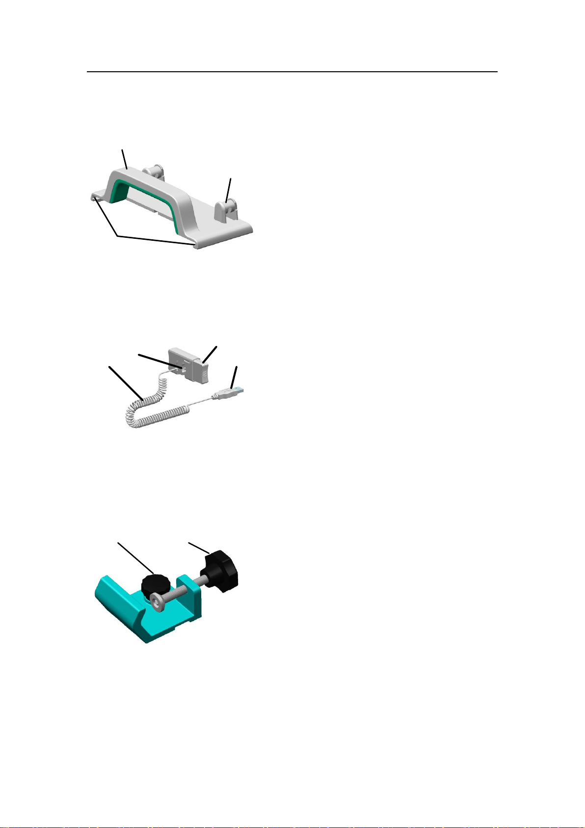
Product Description
1
3
2
1 –Handle
2 –Slide rail
3 –Tubing management bracket
3
2
1
4
1 –Button
2 –Drop hole
3 –Cable
4 –Socket
1
2
1 – Mounting screw
2 – Mounting knob of infusion stand
it is difficult to operate the disconnection device.
4.3 Handle
4.4 Drop sensor
4.5 Pole Clamp
13 / 57
Page 22
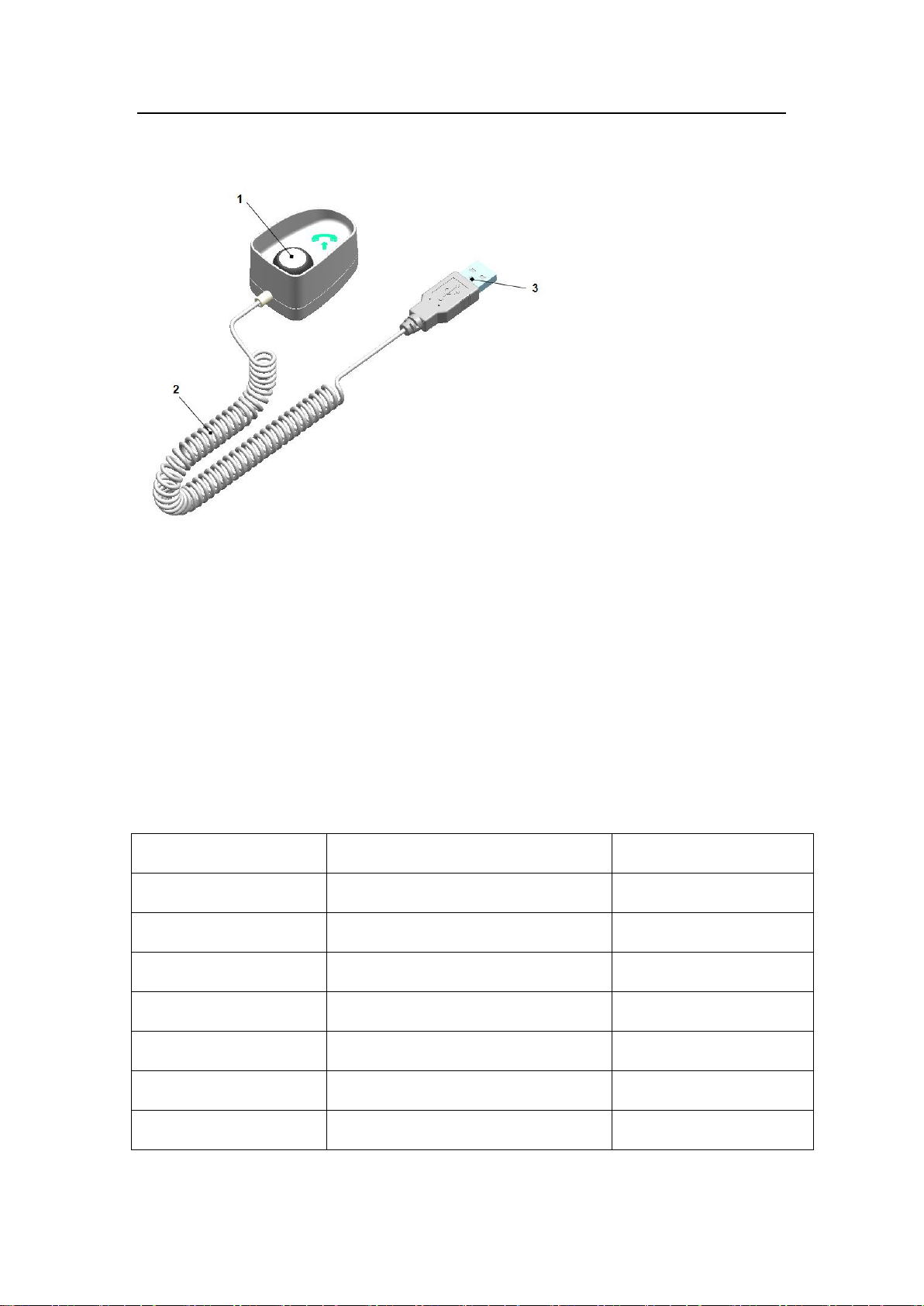
Product Description
1 –Button
2 –Cable
3 –Socket
1 –AC power cord 1
2 – Pole clamp 1
3 – Handle 1
4 – Operation manual 1
5 –Packing list1
6 -– Quick-operation instruction 1
Options
Description
Parts code
Power cable
Standard configuration by factory
7000000005
Lithium battery pack
11.1V@1500mAh
7404000006
Handle
MP-1
9113000002
Nurse pager
MP-2
9113001002
Drop sensor
MP-3
9114002521
Barcode scanner
MP-4
9005000008
Pole clamp
——
9114002501
4.6 Nurse Pager
4.7 Accessories accompanied
4.8 Optional Accessories
Table 4-1 List of Optional Accessories
14 / 57
Page 23

Preparations For Use
5 Preparations for Use
Before using the infusion pump, read carefully the Operation Manual and precautions
in this manual.
When using the infusion pump for the first time, set up the date and time to ensure
that history can be recorded correctly.
Before using the infusion pump for the first time, set the brand of infusion pump.
Before using the infusion pump for the first time, recharge the internal battery fully. If
the infusion pump is off, the battery can be charged fully at least 10 hours after being
connected to an external power supply.
Place the infusion pump on a stable platform.
Or use the provided pole clamp to mount the infusion pump on an infusion stand.
Put the infusion pump on the pole clamp while aligning the retaining knob with
the threaded hole, and rotate the handle to fix the infusion pump on the pole
clamp.
Clamp the pole clamp on the infusion stand, adjust the infusion pump to an
appropriate position, and tighten the retaining knob for infusion stand on the pole
clamp.
Connect external power supply.
Insert the supplied AC power cord into the AC inlet on the right side of the
infusion pump. Plug the cord into an AC power outlet with grounding terminal.
To power the infusion pump with external DC power supply, contact your local
distributor for help.
15 / 57
Page 24
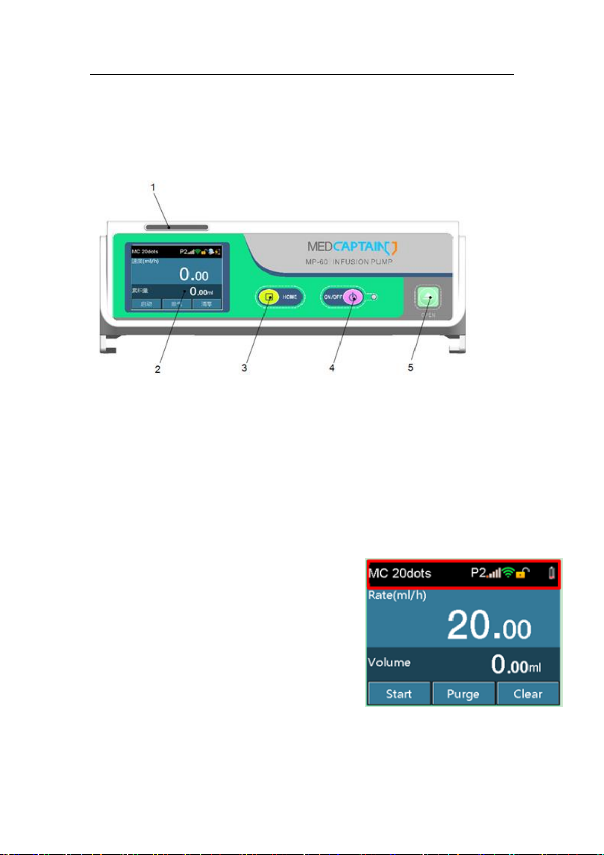
Operating Instructions
1 –Alarm indicator
2 –TFT Touchscreen
3 –Home key
4 –ON/OFF key
5-OPEN key
6 Operating Instructions
6.1 Display and keys
Display
The alarm indicator indicates alarms with three colors: red, yellow and green represent
three levels of high, medium and low, depending on the importance of infusion
information.
TFT Touchscreen, resolution: 320X240
The display is divided into three areas: information area, work data area and function key
area. See below for further description.
Information area: to display the IV set brand and
specification, occlusion level, real- time pressure,
external power source, battery capacity and WIFI signal.
Touch the brand and specifications zone to enter a page
of IV set brand adjustment. Touch the occlusion
pressure level to enter a page of occlusion level
selection. See below for further description.
16 / 57
Page 25
Operating Instructions
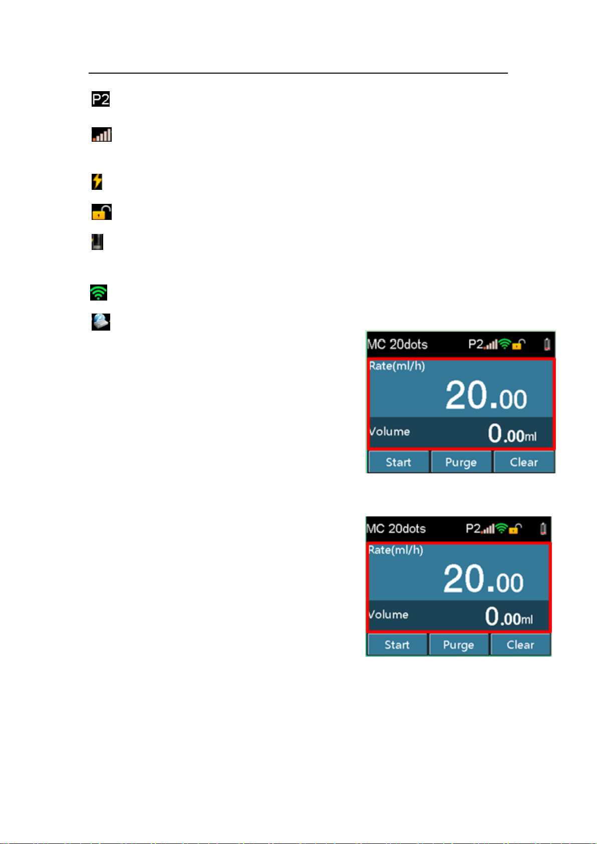
Occlusion pressure level: 2
Occlusion pressure real-time: a full set of 5 bars. The more bars displayed, the larger
pressure it is.
External power source. Displays when external AC/DC power source is connected.
Screenlock symbol, consists of lock and unlock.
Battery volume and charging states: a full set of 4 bars, the more bars displayed, the
larger battery volume.
WIFI signal
Display when connecting to workstation
Work data area: Displays infusion rate, infusion volume
or different infusion work data according to different
infusion mode. The work data could be adjusted by
touching the specific zone in difference working mode.
Function key area: Touchscreen includes keys of [Start],
[Purge], [Clear], [Stop]. Setting keys such as numbers
and letters appear on corresponding interfaces.
17 / 57
Page 26
Operating Instructions
Keys
Except touchscreen keys, there are also 3 keys on the key panel: [HOME],[ON/OFF] and
[OPEN].
[HOME]:Main menu key. Before infusion, press [HOME]once to enter a setting
menu, such as Infusion set, Local set, History and Interconnect set. To return to
the infusion preparing interface, press[HOME]once again in any setting interface.
During infusion, press[HOME]to switch to infusion interface, enlarge and display
the infusion rate.
[ON/OFF]: Switch on/off key. When the pump is off, press [ON/OFF] to turn on
the pump. When the pump is on, press [ON/OFF], and shutdown interface pops
up, select [Power Off]]or long press [ON/OFF]for 3 seconds to shutdown.
[OPEN]: Door open key. Press[OPEN]and the pump door open automatically, no
matter the power is on or off. Push the door forward slightly till you feel the
resistance, the door closes automatically.
6.2 Start up
CAUTION:
Start up and then install the IV set.
Press[ON/OFF]to start up.
The self-test starts and start up interface appears.
After self-test finishes, it enters infusion preparing interface.
The screen displays patient information, infusion brand and occlusion level
stored last time the device powered off.
If the self-test is abnormal, corresponding information will appear on information
area.
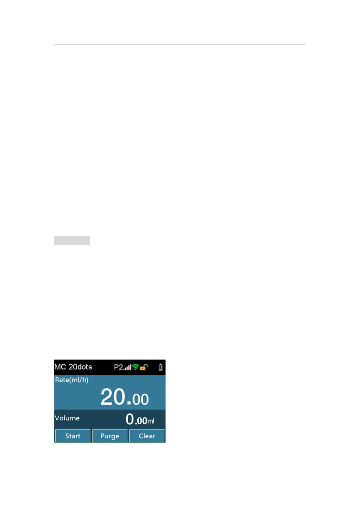
Infusion preparation interface:
18 / 57
Page 27

Operating Instructions
WARNING:
After the power switch is turned on, confirm the loudspeaker, warning indicator is
working all right, and check if the self-test is finished and no error messages appear.
(Refer to Chapter 8 Troubleshooting.)
Ensure the displayed IV set brand corresponds with the using IV set brand.
If the IV set brand set is different from the using IV set brand, the infusion accuracy
and alarm function cannot be guaranteed.
Previous patient information will be cleared if [Yes] is selected on the New Patient
screen.
6.3 IV set installation
Insert the needle into IV bottle vertically, and the liquid infuses into the drop chamber.
When the liquid level is at 1/3 of the drop chamber, open the roller clamp.
Infuse liquid into the tube to purge the air, and then close the roller clamp.
Press [OPEN] to open the pump door.
Press [Anti-Free-Flow Clamp] to open the anti-free-flow clamp, place the tube inside
the clamp, and press the key again to clamp the tube.
Place the tube inside the air bubble sensor and pressure sensor in sequence, then
stretch the tube. Make sure the tube is inside both ends of the tube slit, and then push
the pump door to close it.
CAUTION:
The height range of the liquidcontainer above the PATIENT and/or pumpshould be
20-80cm.
Too loose or too tight tube may cause inaccurate infusion.
The tube must be fixed into the air bubble sensor completely.
19 / 57
Page 28
Operating Instructions
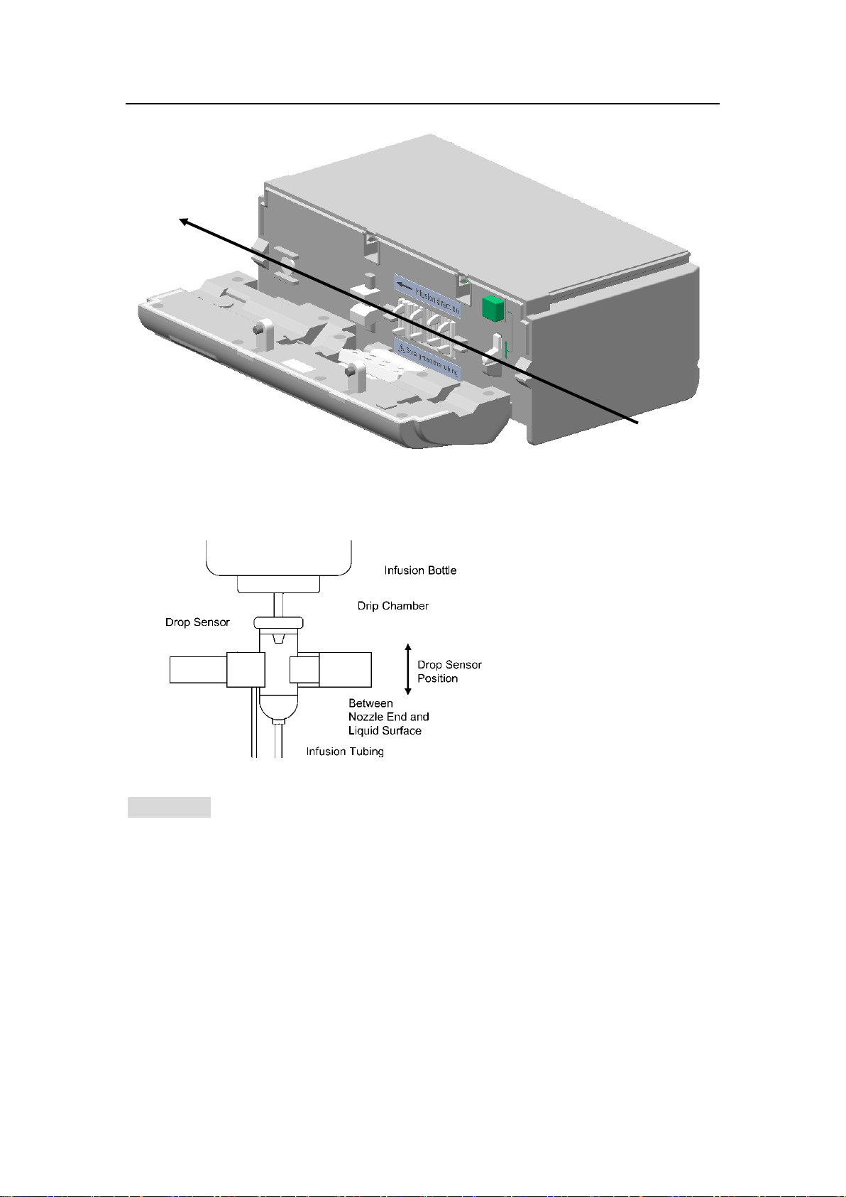
Install the drop sensor
CAUTION:
To ensure the accuracy of drop detection, the drop sensor should be installed as far
as possible close to the down liquid level. The liquid level is approprite to be in the 1/3
of the drop champer.
The liquid level must be lower than the drop sensor.
Prevent the drop sensor from being tilt and always stay out of the sun during infusion.
Avoid the drip bottle is clipped too tight by drop sensor.
Drop sensor detects the drop but not Measures fluids flow. Drop signal are
undetectable if the continuous fluids flow is formed in the drip bottle.
20 / 57
Page 29
Operating Instructions
IV set specification(d/mL)
Purge rate(mL/h)
20
1200.0
6.4 Purge
WARNING:
Before purging the IV line, ensure that the IV line is not connected to patients.
Priming can be done only in non-infusion process.
Ensure liquid has run out from the needle before stopping purging.
Air bubble detection and alarm function wiil be closed during purge.
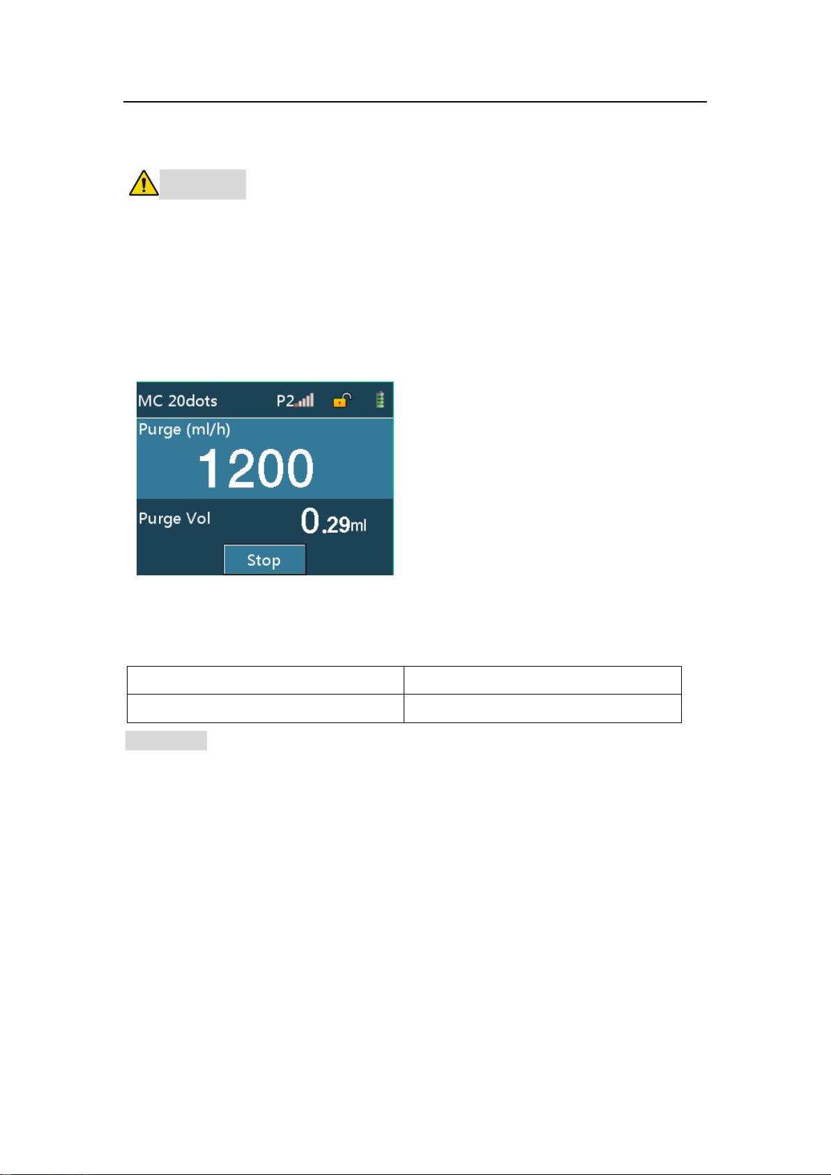
Click [PURGE], then click [yes] on the pop-up interface, the infusion pump would
purge quickly. Click [stop], the purge stops.
The green indicator flashes when purging.
Relationship between IV set specifications and purge rate, refer to the Table 6-1.
Table 6-1 Relationship between IV set specifications and purge rate
CAUTION:
When high viscosity IV fluids are infused through thin vein needle by bolus operation,
occlusion alarm may occur. In such conditions, reduce the infusion speed to purge.
Total volume cannot be cleared after infusion starts.
The volume under the purge function will not be calculated into the total volume.
6.5 Setting the infusion rate
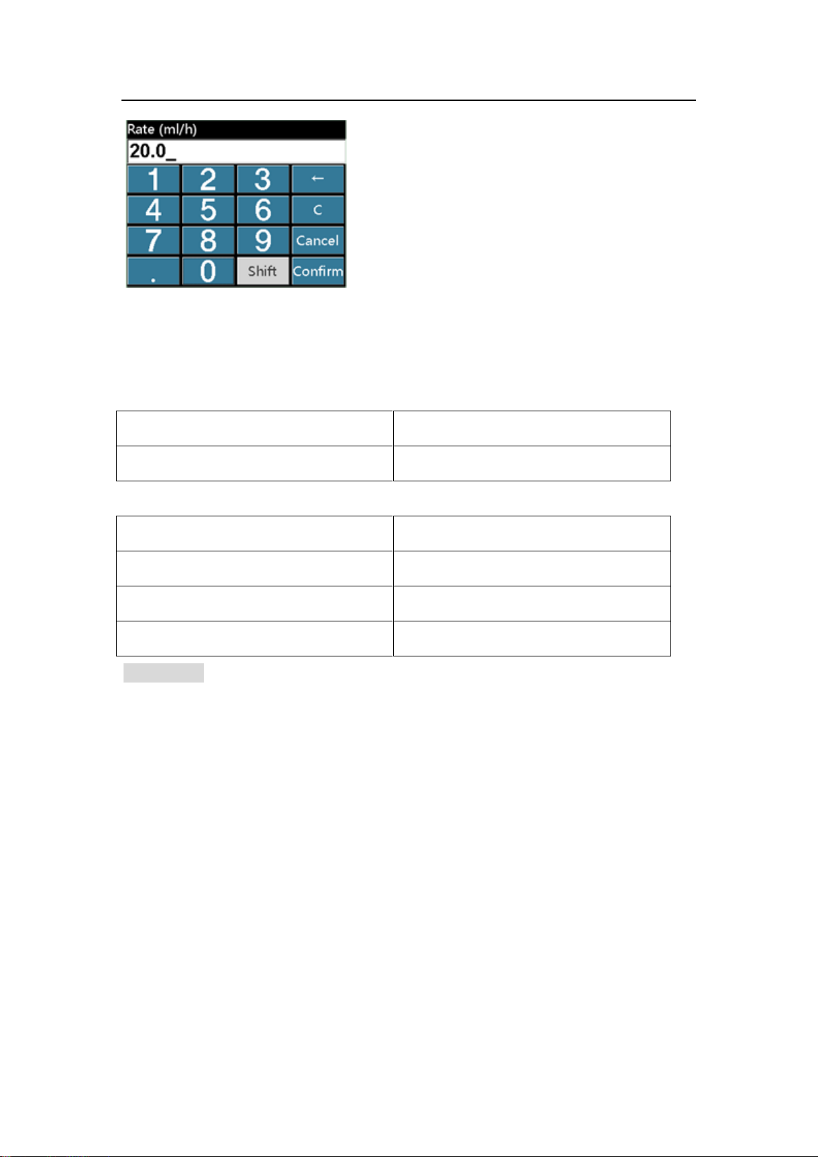
Click the rate area on the Touchscreen to enter the setting interface.
21 / 57
Page 30
Operating Instructions
IV set specification (d/mL)
Setting range (mL/h)
20
0.1-1200.0
Rate range(ml/h)
Minimum increment(ml/h)
0.10 - 99.99
0.01
100 - 999.9
0.1
1000 - 1200
1
Click [CLEAR] to clear the total volume.
Relationship between IV set specifications and range, see Table 6-2. The minimum
increment see Table 6-3.
Table 6-2 Relationship between IV set specifications and range
Table 6-3 Relationship between rate range and the minimum increment
CAUTION:
If the flow rate is changed in the infusion process, the infusion will be done at the new
flow rate.
6.6 Puncture
Insert the vein infusion needle into the patient’s vein.
6.7 Starting Infusion
Click [START], start infusion at the setting rate and green indicator flashes.
22 / 57
Page 31
Operating Instructions
CAUTION:
Infusion can only start when the recipe value equals to the set value.
If no operation is performed after IV set installation for more than 2 minutes,
START-REMINDER alarm sounds.
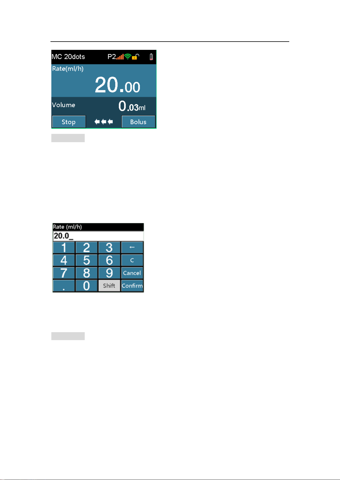
6.8 Change rate during infusion
Click the rate display area on the screen, enter and change the rate on the pop-up
interface.
After entering the rate, if click [Cancel], it will return to original infusion interface
without change; Click [Confirm], it will return to original infusion interface and operates
at the new rate.
CAUTION:
If no operation is performed in reference and setting rate interfaces for more than 10
seconds, it will return to infusion interface automatically.
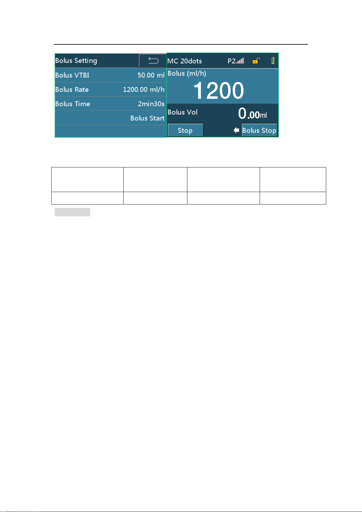
6.9 Bolus
During infusion; click [Bolus] to enter the bolus setting interface. Set any two of Bolus
VTBI, Bolus rate and Bolus Time, click [Bolus Start] to enter the bolus interface, click
[Bolus Stop] to stop the bolus.
23 / 57
Page 32
Operating Instructions
IV set specification
(d/ml)
Bolus rate(ml/h)
The minimum bolus
volume(ml)
The maximum
bolus volume(ml)
20
0.1-1200.0
0.1
50.0
Bolus rates are different depending on the IV set specification as follows.
Table 6-4Relationship between IV set specification and flow rate
CAUTION:
Current bolus volume is displayed when bolus is running.
Bolus volume will be accumulated into the total volume.
6.10 Stopping Infusion
In the infusion process or after infusion, press the [STOP] key to stop the operation
and green indicator will be off.
6.11 Replacing or adjusting IV set
An extrusion damage of tube in continuous infusion of the IV set would affect the
infusion precision. After about 8-hour or regulated hour continuous infusion of the IV set,
the infusion should be stopped, open the pump door, and move the IV tube about 10 cm
from the original position, so that the IV tube functions better. Changing the whole IV set is
better solution.
24 / 57
Page 33
Operating Instructions
6.12 Turning the Power Off
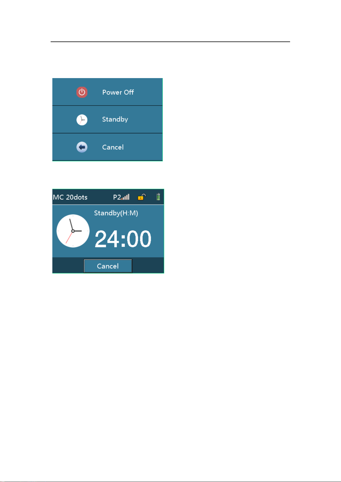
Press the [ON/OFF] key, choose Power Off, Standby or Cancel.
Click [Power Off] to shutdown.
Click [Standby] to enter standby interface, the standby time can be modify.
Click [Cancel] to return to previous interface.
.
25 / 57
Page 34
Setting the Infusion Pump
7 Setting the InfusionPump
CAUTION:
After the pump is shutdown, all parameter settings will be automatically saved.
Parts of parameters will not be saved in force shutdown.
7.1 Infusion set
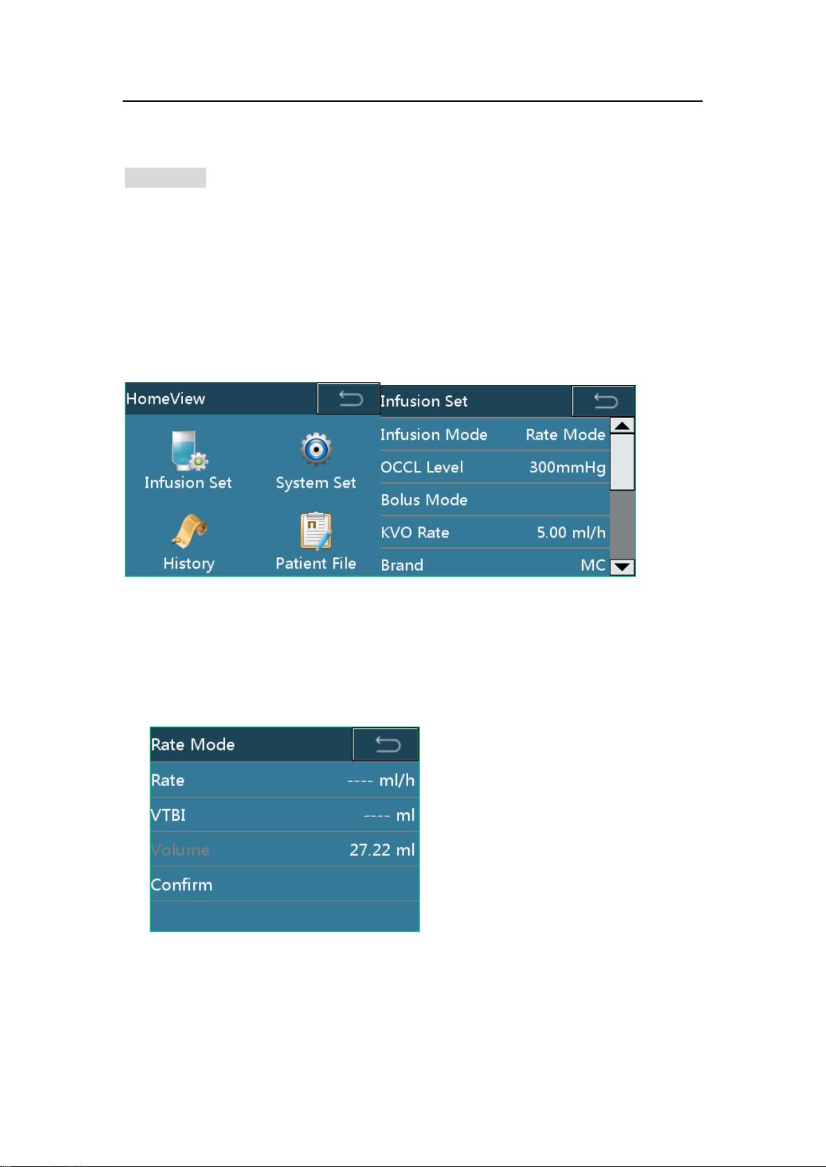
Press [HOME] key to enter the setting interface, click [Infusion Set] to enter the
detailed infusion setting interface. Infusion set, occlusion level, bolus mode, KVO rate,
brand, relay set,near finished could be set and adjusted here.
7.1.1 Infusionmode
5infusion modes: Rate, Time, Weight, Sequence, Dripare aer available
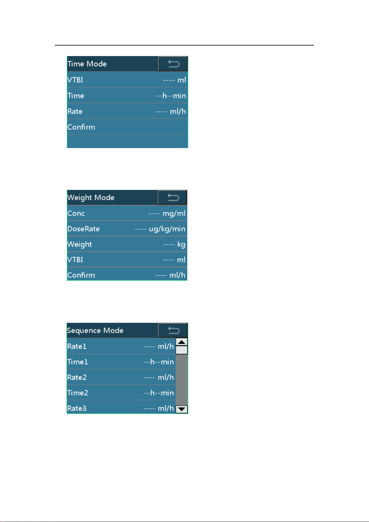
Rate mode
Under the Rate Mode, set the rate and VTBI, click [Confirm] to operate.
Time mode
Under theTimeMode, set the VTBI and Time, the rate will be calculated automatically,
click [Confirm] to operate.
26 / 57
Page 35
Setting the Infusion Pump
Weight mode
Under the WeightMode, set the Conc, DoseRate, Weight and VTBI, the device will
calculate the rate automatically. Click [Confirm] to operate.
Sequence Mode
Under the Sequence Mode, set the 5 sequence rate and time, click [Confirm] to
operate in sequence.
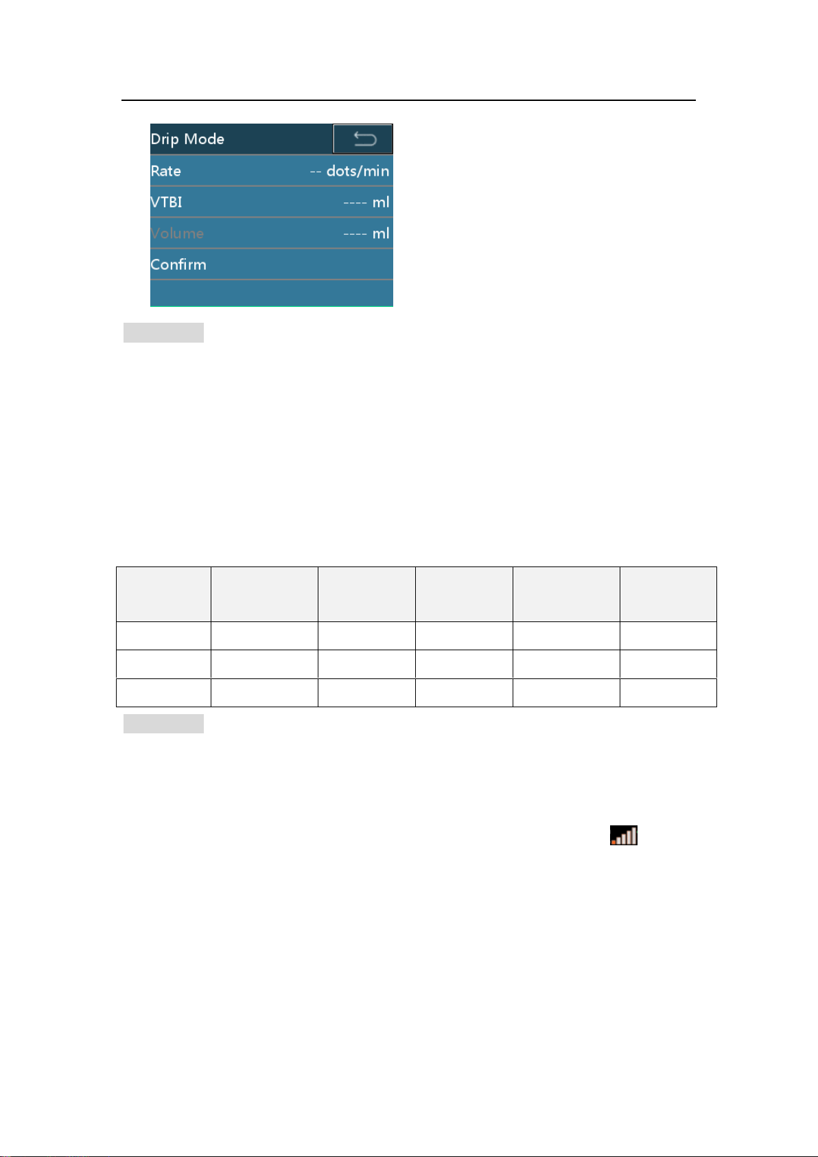
Drip Mode
Under the Drip Mode, set the rate and VTBI, and then click [Confirm] to operate.
27 / 57
Page 36
Setting the Infusion Pump
Occlusion
level
Display
Pressure
(mmHg)
Pressure
(Kpa)
Pressure
(bar)
Pressure
(psi)
1
P 1
300
40
0.4
5.8
2
P 2
550
73
0.7
10.6 3 P 3
900
120
1.2
17.4
CAUTION:
The pump will calculate the corresponding rate according to the current drip rate
(dots/min) and current IV set’s spec.
The pump control the flow by using corresponding flow rate (ml/h) but not by
detecting the drip rate (dots/ml).
7.1.2 Occlusion Level
3 levels of occlusion are available (Factory setting is level 2).
Table 7-1 Relations between occlusion level and pressure
CAUTION:
To preventthe unblocked alarm to cause patients with extra amount of pills after input,
Anti - Bolus alarm, electric opportunity back automatically release line pressure.
When you infuse viscous solution with the Occlusion Level setting on level1 and the
tubing is clear, occlusion alarm tends to be issued. Carefully watch the on the
upper information area, and change the occlusion level if above 2 bars appear.
When you operate the pump with the Occlusion Level setting on level 3, the in-line
pressure builds up substantially until Occlusion alarm is issued. Always make sure
that the IV line is securely connected to the pump.
Occlusion alarm may occur when high-viscosity liquid is infused at high speed
through a thin intravenous needle. Increase the occlusion level or decrease the
infusion speed.
28 / 57
Page 37
Setting the Infusion Pump
7.1.3 Bolus Mode
There are three modes: Manual Bolus, Rapid quantitative Bolus and Automatic Bolus.
Please refer to the chapter 6.9 for further instructions.
7.1.4 KVO Rate
KVO-rate could be adjusted from 0.1ml/h to 5ml/h (Step by 0.01ml/h), Default rate:
1ml/h.
7.1.5 Brand
You can choose the consumable brand by: [Home] -> [Infusion Set] -> [Brand].
Several brands of 20d/mL IV set have been preset and customized. Select the
infusion accordingly for clinical uses.
CAUTION:
Users must use the consumable brand which is specified by the manufacturer.
To add in infusion of other brand, users are strongly recommended to contact the
manufacturer or manufacturer’s representative to set and test, so as to ensure the
infusion accuracy.
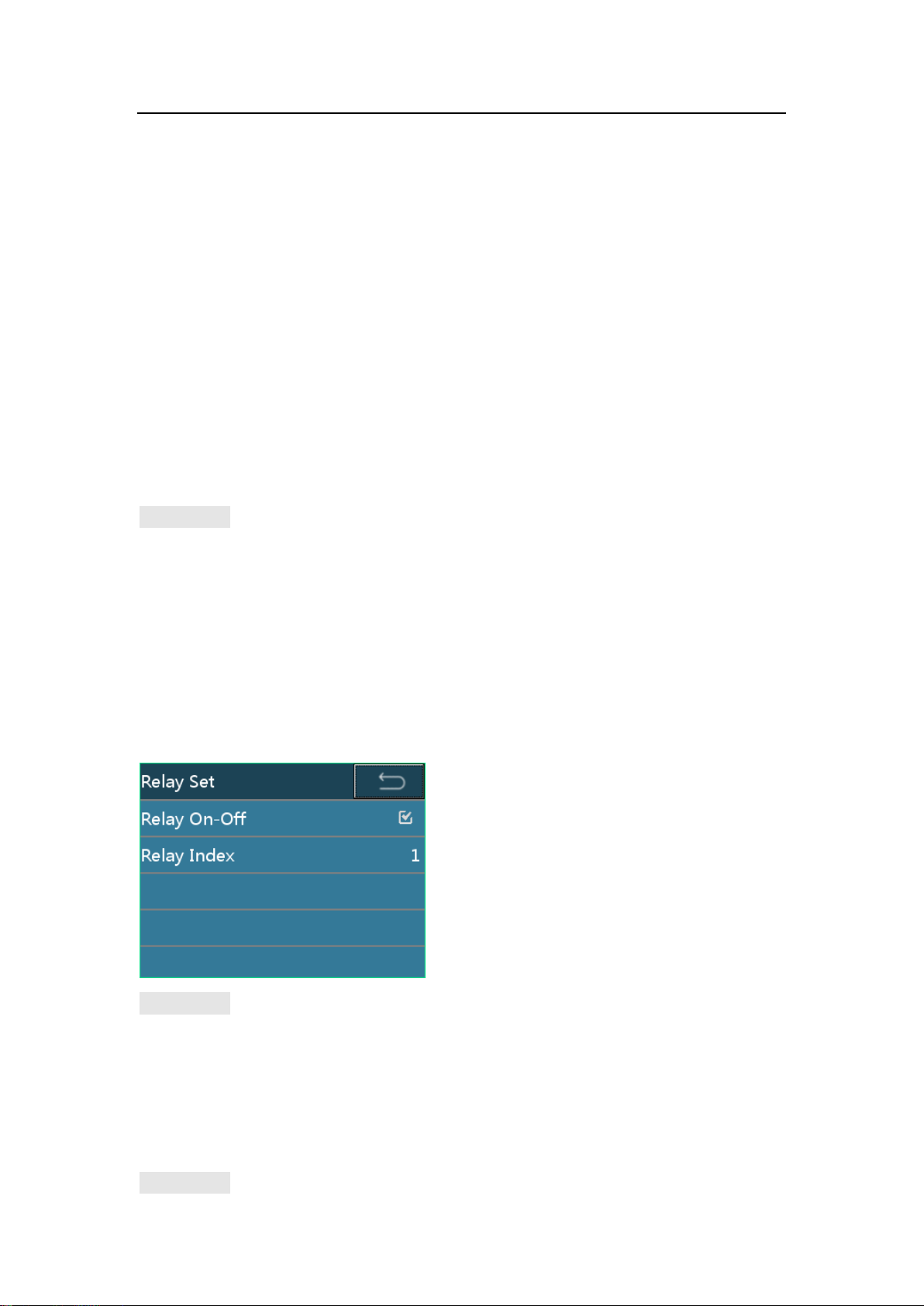
7.1.6 Relay set
Open relay mode, set the relay number under the mode.
CAUTION:
The relay number must be set in sequence from number 1 when there are several
infusion pumps or infusion pumps.
7.1.7 Drip Mode Set
Open the drip mode, detect the drop sensor and count the drops during infusion.
CAUTION:
29 / 57
Page 38
Setting the Infusion Pump
If disconnected the drop sensor but the drip mode is open, the pump produces no
drop sensor alarm.
7.1.8 NearFinished
Near Finished Alarm: Alarm-time could be adjusted from 1min to 30min before
Finished (Step by1min), Default time: 3min before Finished.
7.2 System Set
7.2.1 Volume Setting
11 volume levels are available (The factory setting is level 5).
CAUTION:
Do not set an alarm volume that is lower than the environment noise, or it may cause
the alarm system to be out of work or the alarm cannot be correctly recognized timely.
If setting alarm to extreme values that can render the alarm system useless. Check
the alarm limited according to clinical condition.
If the pump is inserted to a working station, once the volume setting on the pump is
changed, the setting on the station will be synchronized at the same time.
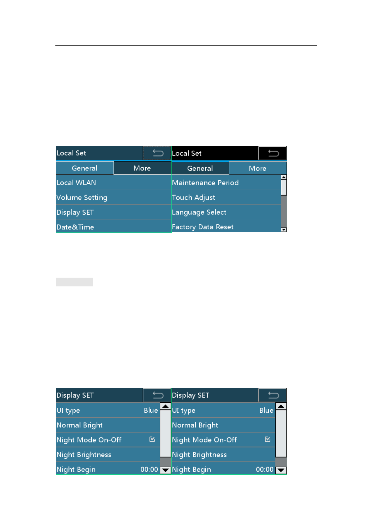
7.2.2 Display SET
30 / 57
Page 39
Setting the Infusion Pump
There are seven different color options for UI type.
The brightness could be adjusted in [Normal Bright].
All the parameters of the night mode could be adjusted here.
CAUTION:
Under the night mode, setting range of start time is 17:00-09:00, finish time range is
the same as start time range. By default, the start is 00:00; finish time is 00:00.
If the pump is inserted to a working station, once the display setting on the pump is
changed, the setting on the station will be synchronized at the same time.
7.2.3 Internet Set
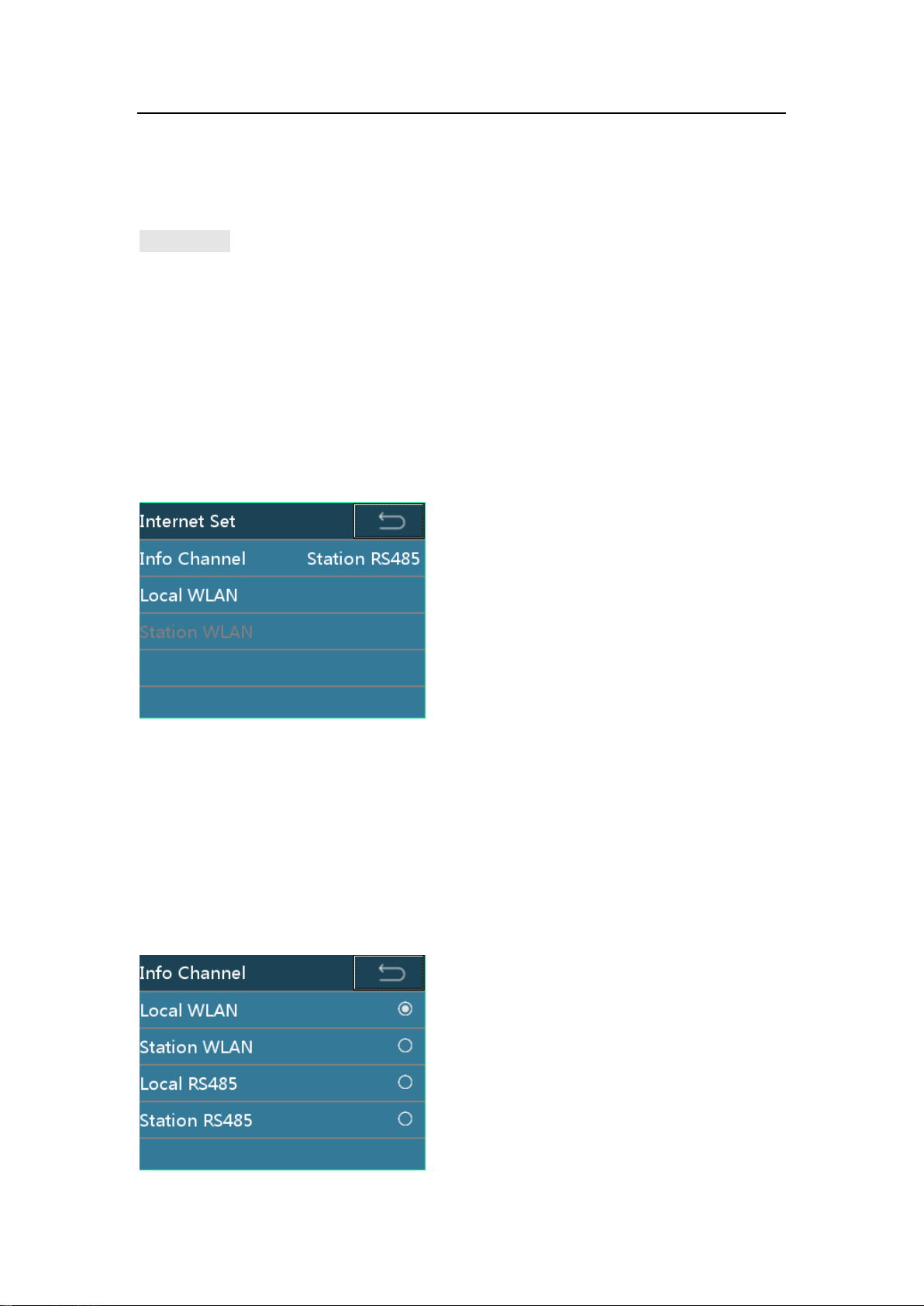
[Info Channel], [Local WLAN], and [Workstation WLAN] (not available if the pump is
not connected to a workstation) could be chose and set.
Click [Info Channel] to choose the channel type.
Choose [Local WLAN] to use local WLAN channel to connect to the network, and
the local WLAN parameters could be set.
Choose [Station WLAN] to use station WLAN channel to connect to the network,
and the station WLAN parameters could be set.
Choose [Local RS485] to use local RS485 cable to connect to the network.
Choose [Station RS485] to use station RS485 cable to connect to the network.
31 / 57
Page 40
Setting the Infusion Pump
CAUTION:
The pump could communicate with working station, and the working station could
manage the alarm and implement relay function between pumps.
The setting of [Local RS485] and [Station RS485] must be done by the
manufacturer’s representatives. Please contact manufacturer or local dealer for
further information.
Only the accessory or devices supplied or specified by manufacturer allowed to be
connected with the pump. Otherwise it may cause the pump not work normally or
other unpredictable hazards.
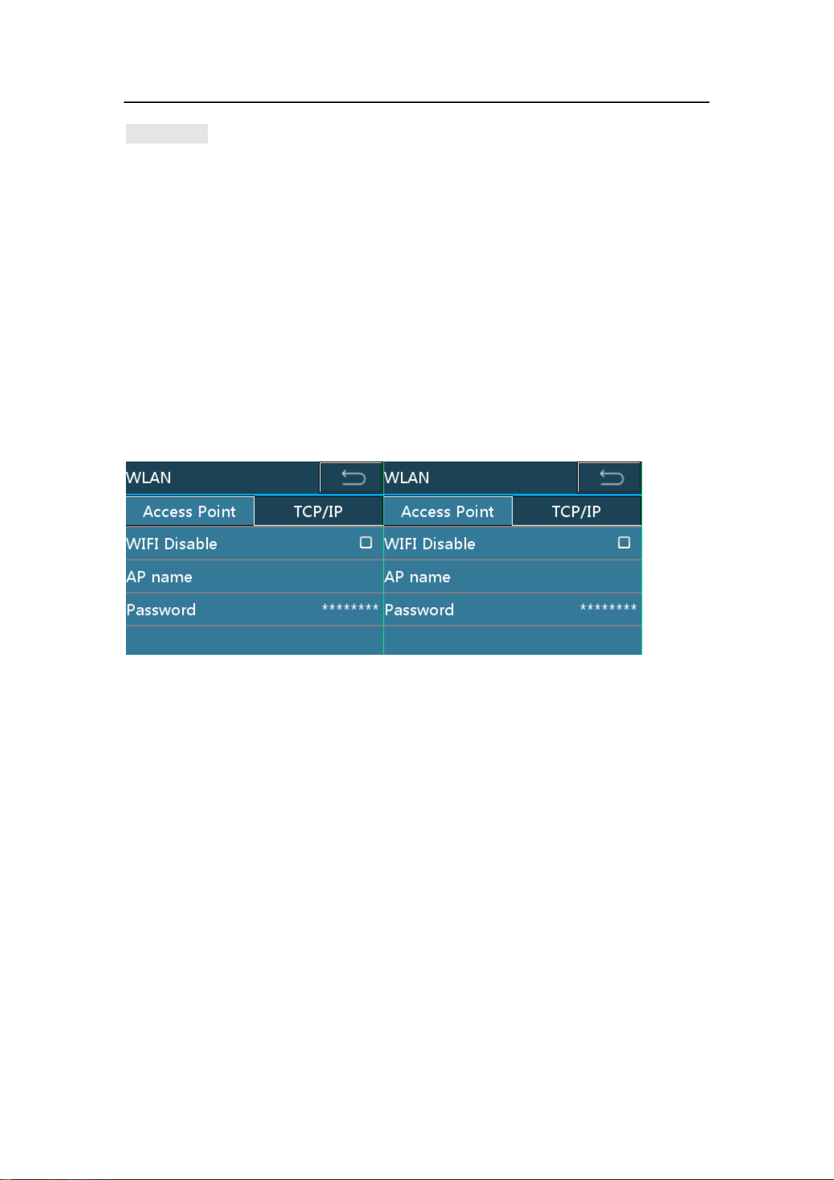
Click [Local WLAN]/[Station WLAN] to set up WLAN parameters.
[WIFI Disable] option should be cancelled, the AP name, Password of the network
should be inputted, and the TCP/IP’s information should be set.
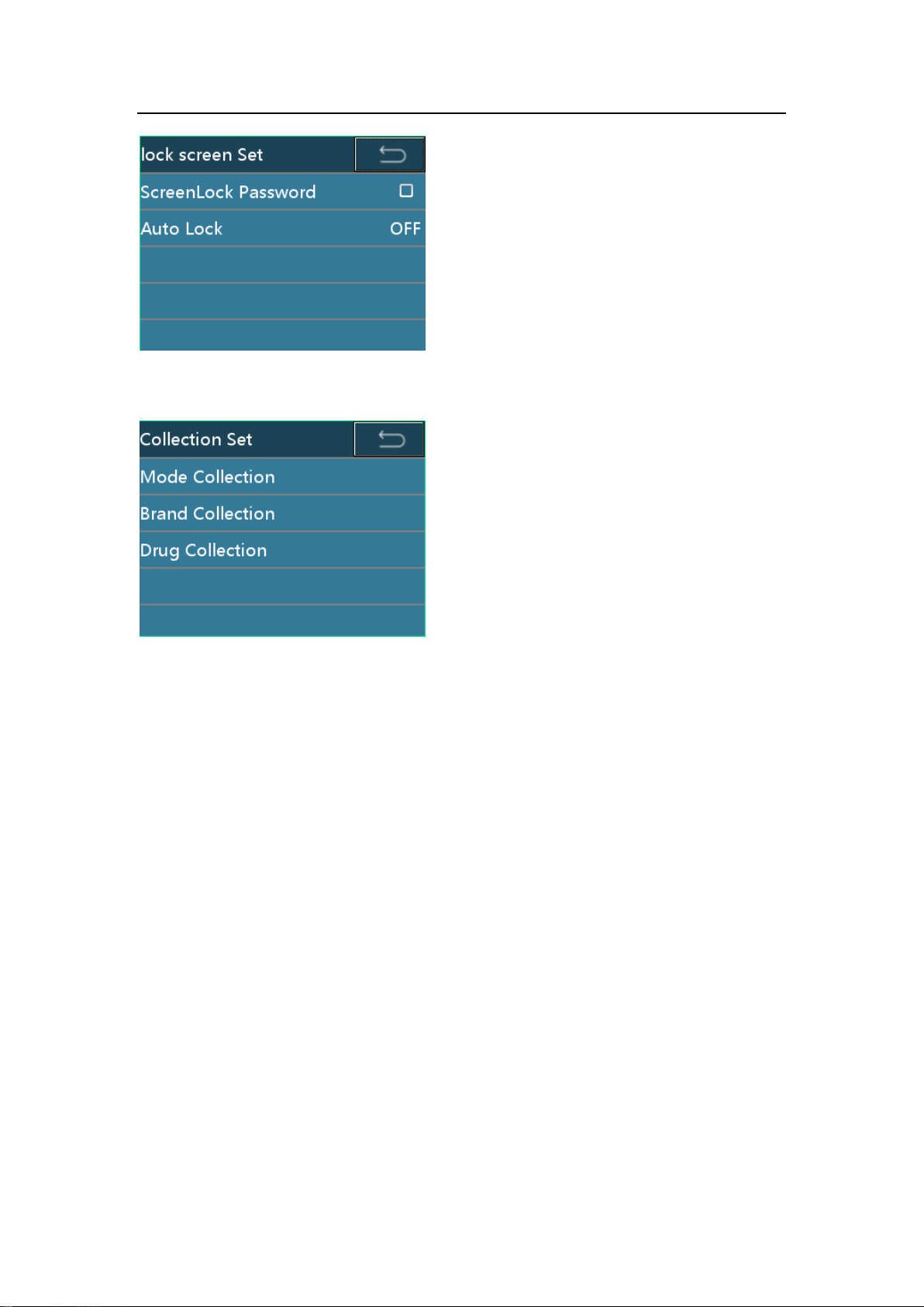
7.2.4 Lock screen Set
Click [ScreenLock Password] to enable/disable the screen lock password function.
When the function is enable, a password is required to unlock the screen. When the
function is disable, there will be no require on password to unlock the screen.
Click [Auto Lock] to set up the screen auto lock function. This function could be set as:
OFF, 15s, 30s, 1min, 2min, 5min, 10min, 30min. The default value is OFF, which
means the screen auto lock function is disable.
32 / 57
Page 41
Setting the Infusion Pump
7.2.5 Collection Set
[Mode Collection]: Choose the frequently used infusion mode from the [Infusion mode]
option. Once the frequently used infusion modes are chosen, the unnecessary modes
will not appear in the list of 7.1.1 [Infusion mode] option. The default setting is “all the
four infusion modes are chosen”.
[Brand Collection]: Choose the frequently used infusion set’s brand from the [Brand]
option. Once the frequently used brands are chosen, the unnecessary brands will not
appear in the list of 7.1.5 [Brand] option. The default setting is “all the preloaded
brands are chosen”.
7.2.6 Linkage mode
If the linkage mode is turned on, press the anti-free flow clamp button to open the
clamp, and release the button to clamp the tube.
33 / 57
Page 42
Setting the Infusion Pump
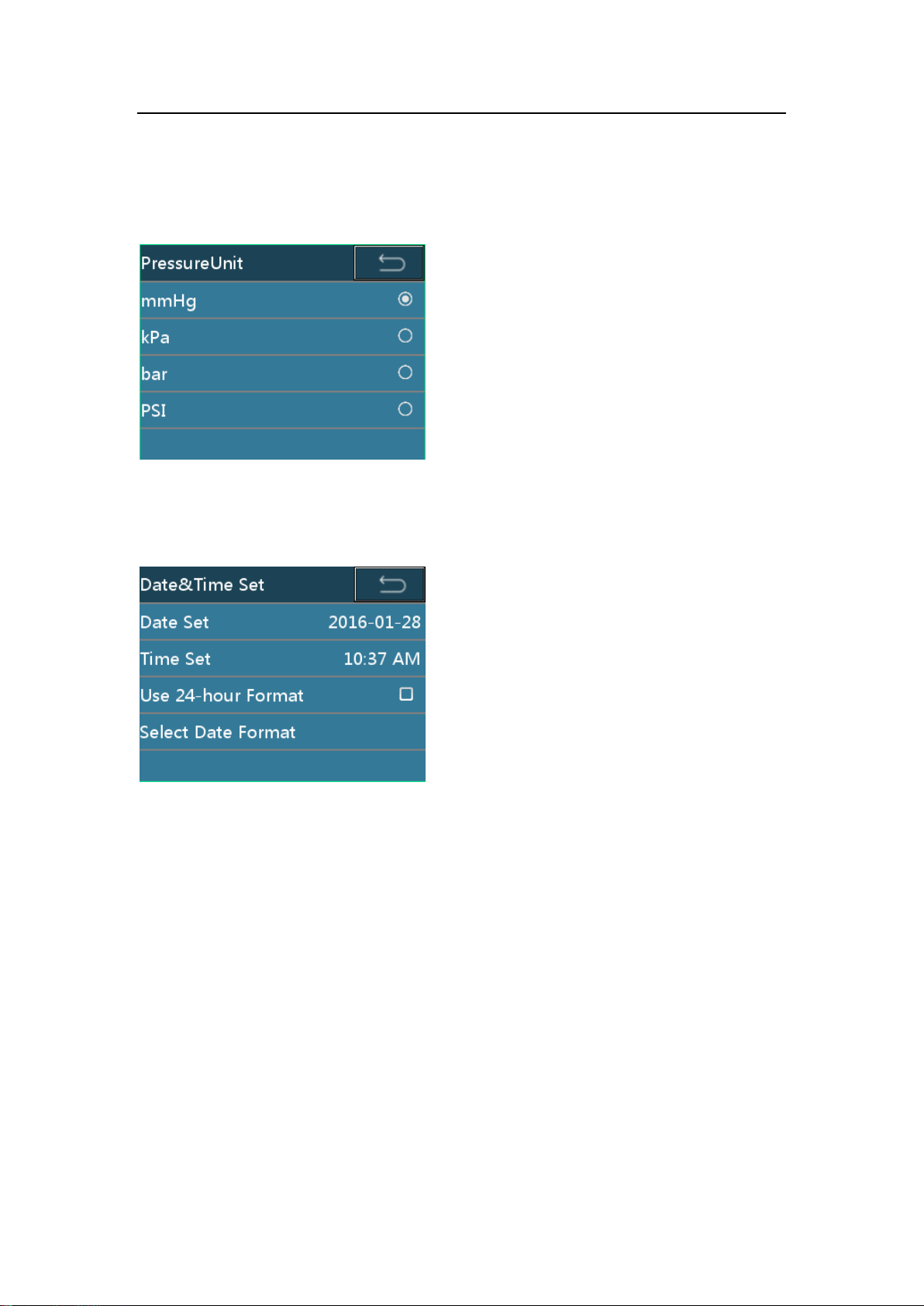
7.2.7 PressureUnit
Choose the measurement unit for the pressure. The optional units are: mmHg, kPa,
bar and PSI. The default setting is mmHg.
7.2.8 Date&Time set
Set the date, time, and their format.
7.2.9 Maintenance
Click [Maintenance] option to do the [Language Select], [Touch Adjust], [Factory Data
Reset], and check the version information.
To check the version information, follow the route of: [Home] -> [System Set] ->
[Maintenance] -> [Version Info].
34 / 57
Page 43
Setting the Infusion Pump
Event
Record Parameters
Start up
Occurred time
Shutdown
Occurred time
Standby
Occurred time, standby set time
Start
Occurred time, rate, VTBI
Bolus
Occurred time, Bolus rate, Bolus way
Bolus stop
Occurred time, Bolus rate, Bolus accumulated volume
Stop
Occurred time, rate, accumulated volume
KVO
Occurredtime, accumulated volume, KVO rate
KVO stop
Occurredtime, KVO rate,KVO accumulated volume
Flow rate change
Occurredtime, Flow rate before and after change
Alarm
Occurredtime, alarm event, system trouble with trouble code
Purge
Occurredtime, purge rate, accumulated volume
Purge stop
Occurredtime, purge rate, purge accumulated volume
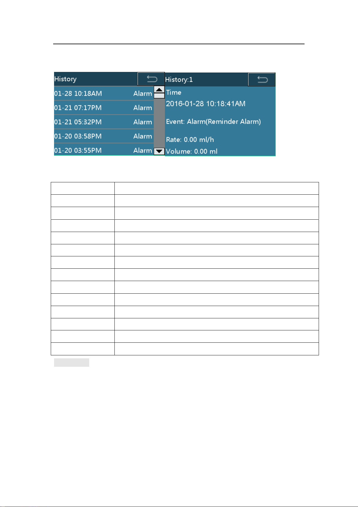
7.3 History
The history records are as Table 7-2.
Table 7-2 History records
CAUTION:
2000 history records are available to be stored at maximum. If the amount reaches
storage limit, the earliest record would be removed.
Alarm system can’t be poweredoff separately by operator unless the pump is
powered off.The time of powering off is captured in the history records.
35 / 57
Page 44
Setting the Infusion Pump
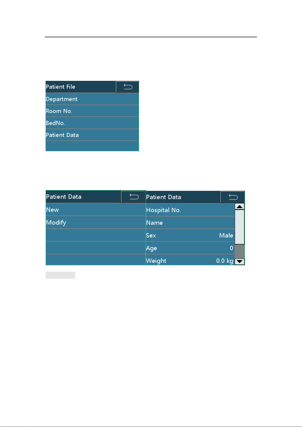
7.4 Patient File
Click [Patient File] to enter the patient file page. The [Department], [Room No.], [Bed
No.] and [Patient Data] could be set up.
Click [Patient Data] option to enter patient data setting page. Choose [New] to build a
new patient data and the previous patient data will be cleared automatically. Choose
[Modify] to modify the current patient data.
CAUTION:
If the pump is inserted to a working station, once the patient file on the pump is
changed, the data on the station will be synchronized at the same time.
7.5 Use Internal battery
If there is not any AC/DC power supply, the internal battery operates.
When external battery stops working, the internal battery starts and the yellow
indicator lights with a short alarm sound.
Before first use or reuse before a long time, please charge at least 10 hours.
The approx. remaining power in the built-in battery is displayed by [battery] indicators.
During battery operation, battery discharged is shown by a decreasing number of
active indicators. For details, see Table 7-3.
36 / 57
Page 45

Setting the Infusion Pump
[Battery capacity]state
The remaining capacity*1)
Four bars light
Operation will be possible for 300 minutes.
Three bars light
Operation will be possible for 210 minutes.
Two bars light
Operation will be possible for 140 minutes.
One bars light(green)
Operation will be possible for 70 minutes.
One bars light(red)
Operation will be possible for 30 minutes.
Table 7-3when battery works, the [Battery capacity] diagram state
*1) Working conditions:
New battery (within one year of manufacture).
Operating at 25mL/h using a 20d/ mL infusion. Close WIFI function.
Room temperature of 25°C.
When the infusion pump is connected to any external AC or DC power supply, the
charge of the built-in battery starts. When battery is charging, a lightning symbol will
be displayed at the left side of the battery symbol on the screen.
CAUTION:
If AC or DC power is connected, the battery will be recharged.
Use AC power to charge the battery. If recharged by an external 12 VDC power
supply, the battery cannot be fully charged (50% at most).
During infusion and the pump powered by battery, if a low-battery alarm occurs, press
[SILENCE] to silence the alarm will repeat in two minutes, connect the pump to
AC/DC power supply immediately. If battery empty alarm occurs, the silence does not
function and infusion pump will stop.
3 minutes before the battery empty, the pump will auto power off.
New battery fully charged at 1200 ml/h rate of infusion, the battery of continuous use
time is 2h42min.
The actual battery duration may be different and affected bythe ambient temperature,
flow rate, external communication, etc.
If the battery is aging,the actual battery duration may be shorter. Periodically check
the battery.
37 / 57
Page 46

Setting the Infusion Pump
7.6 Connecting to the <Infusion Central Monitoring
System>(optional)
Infusion pumps can be connected to the < Infusion Central Monitoring System >,
which can obtain working states of pumps remotely.
CAUTION:
Infusion pump cannot be operated through the < Infusion Central Monitoring
System >.
7.7 Nurse pager (optional)
After infusion pump is connected to the central station, patient can press nurse pager
in bed, and then the central station in nurse station would gives out sound tip and display
patient’s information in screen, so that the nurse can take care of the patient in time.
7.8 Voice communication(optional)
After infusion pump is connected to the central station, patient can press nurse pager
in bed, and then the central station in nurse station would gives out sound tip. Nurse can
press the talk-listen button and communicate with patient in real time to know the
information.
7.9 Connecting a barcode scanner (optional)
After a barcode scanner is connected to the pump, the patient information, such as
record No. and hospital No., can be scanned, and the patient information in the pump will
update automatically by pump prompts.
The barcode scanner can scan maximum 18 figures.
7.10 User-specific Requirements (optional)
7.10.1 Maximum Flow rate
Parameters the maximum flow rate is already set with the infusion pump. For any
modification, contact your local distributor.
38 / 57
Page 47

Troubleshooting
Alarm
Sound
Light
Low-level alarm
Give out three beeps at intervals
of 25 seconds.
The yellow indicator keeps on.
Mid-level alarm
Give out three beeps at intervals
of 15 seconds.
The yellow indicator flashing.
High-level alarm
Give out a series of beeps at
intervals of 15 seconds.
The red indicator flashing.
8 Troubleshooting
8.1 Alarm
The infusion pump provides users with a variety of status information about itself and
its injection process. If any abnormality is detected, the infusion pump sounds an alarm
and notes users in the form of sound, light, and character.
All the alarms on this pump are the technical type alarm.
Considering the importance of abnormal information, alarm information is classified
into three levels from the viewpoint of security: low-level, mid-level, and high-level alarms.
For audio and visual expressions of alarms at three levels, see Table 8-1. The alarm
volume ranges from 45 dB to 85 dB.
Table 8-1 Alarm severity and the audio and visual expressions of each level
When an alarm occurs, press [SILENCE] to silence the alarm. But the buzzer beeps
again if you do not eliminate the mid/high-level alarm within 2 minutes.
CAUTION:
The setting of the alarm will be saved permanentlywhen the power is cut. When the
pump restarts from a power failure situation, the alarm setting will be reloaded to the
system and remains the same as it was before the power failure.
WARNING:
Potential hazard can exist if differentALARM PRE-SETS are used for the same or
similarequipment in any single area.
39 / 57
Page 48

Troubleshooting
Alarm Symptoms
Alarm level
Causes
Troubleshooting
No Power Supply
Low-level
No external AC/DC power
supply is connected.
Immediately connect the AC
power supply or the external
DC power supply.
No Battery
Mid-level
The infusion pump has no
internal battery or the
internal battery operates
abnormally.
Replace the internal battery.
Low Battery
Low-level
The internal battery is
running critically low.
Immediately connect an AC
power supply or an external
DC power supply.
Battery Empty
High-level
The battery is out.
Immediately connect an AC
power supply or an external
DC power supply.
Near End
Low-level
The infusion is end within
the Near Finished Alarm
setting period.
Wait until the infusion
finishes.
Occlusion Alarm
High-level
1.The infusion IV line is
occluded;
2. The OCCL level is too
low for high viscosity drug’s
infusion.
Press [STOP] to stop the
injection. Check and
remove the cause,
continuous to inject.
Air-bubble
High-level
1. Air bubble in the infusion
line.
2. The flatten tube is fixed
inside the air bubble
detector.
Click [Stop] to remove the
alarm, check if the tube
installed in air-bubble probe
is roll flattening. Press
[PURGE] to release air
bubble quickly.
Finished
High-level
The limit amount or the
infusion time is complete
Press [STOP] to remove the
alarm.
Reminder Alarm
Low-level
Forget to operate the alarm
(no key operation is made
two minutes after the IV
sets is installed).
Press any key to clear the
alarm.
8.2 Faults and Troubleshooting
Table 8-2 Alarm symptom, alarm level,fault cause, and troubleshooting
40 / 57
Page 49

Troubleshooting
Alarm Symptoms
Alarm level
Causes
Troubleshooting
Drop Error
Low-level
The drip rate is detected to
be incorrect at the drip
kettle during the infusion.
Press [Cancel] to remove
alarm. And check the
installation of the drop
sensor.
No drop sensor
Mid-level
The drop sensor detection
function is turned on, but
drop sensor is not installed.
Install the drop sensor, or
turn the drop sensor
detection function.
No drop
High-level
No drop is detected by the
drop sensor.
Press [Stop] to remove
alarm, check the installation
of the drop sensor and the
IV set.
Standby Time
Expired
Mid-level
Standby mode is end
Press cancel to exit
Standby mode.
Relay Index
Duplicate
High-level
Relay Index Duplicate
Reset Relay Index
Infusion Start Fail
High-level
Infusion pump cannot be
started under the relay
mode.
Check the infusion pump,
remove the problem that
causes the failure of start.
Trouble code
Alarm level
Troubleshooting
Sensor Error
High-level
Record the troublecode and turn off, contact manufacturer
or manufacturer’s representatives.
Motor Error
High-level
Circuitry Error
High-level
Diver COM Error
High-level
Pump finger error
High-level
Pump door error
High-level
Bubble sensor error
High-level
System Error
High-level
8.3 Troubles and trouble shooting
When the device goes wrong, a corresponding trouble code appears in the interface
and gives out high-level alarm.
Table 8-3 troubles and troubleshooting
41 / 57
Page 50

Maintenance
9 Maintenance
9.1 Cleaning, Disinfecting
Before cleaning the pump,be sure to turn off the power and disconnect the AC or DC
power cables.
If there is dirt on the pump,wipe it with wet soft cloth dampened with cold or
lukewarm water.
Use a piece of dry soft cloth to clean the AC power supply socket, USB socket or the
nurse call socket,ensure that the socket is dry before using it.
Do not use organic solvent such as alcohol or thinner.
If disinfection is necessary,using the common disinfectors such as Chlorhexidine
gluconate and Benzalkonium chloride. After using the agent with a soft cloth,wipe off
it with a soft cloth dampened with water or warm water. When using the disinfecting
agent,follow the caution of each agent.
The infusion pump cannot be autoclaved.
Never use a dryer or similar device to dry the infusion pump.
If liquid spills onto the pump, check whether the pump still functions normally. Test
the insulation and leakage current when necessary.
Do not soak the infusion pump into water.
WARNING:
Do not clean or sterilize the pump when it is running.
9.2 Periodic Maintenance
Perform a periodic maintenance inspection to ensure safe operation and the longest
possible life of the infusion pump,and check the infusion pump once every 2 years.
Contact manufacturer or manufacturer’s representatives for any doubt.
9.2.1 Checking the Appearance
Appearance checking: There are no cracks and damages.
Key operations: If the keys are pressed smoothly, they are available.
9.2.2 Checking the Power Cable
Check the appearance of the power cable. If the appearance is damaged and the
plug and the socket are in poor contact, contact manufacturer or manufacturer’s
42 / 57
Page 51

Maintenance
IV set
Infusion rate
Infusion time
Volume in graduate
MC/B.Braun20d/mL
120mL/h
6min
11.4-12.6mL
IV set
Infusion rate
Occlusion level
Alarm time
MC/B.Braun
20d/mL
120mL/h
P2
Within 1 minute
representatives for replacement in time.
If you connect the infusion pump to the AC/DC power and there is no indication of
powering on, contact manufacturer or manufacturer’s representative for maintenance
in time.
9.2.3 Checking the infusion rate
Check the infusion flow once every 2 years by the graduate and timer.
Checking condition:
9.2.4 Alarm
Occlusion alarm
Checking condition:
Air bubble alarm
Add in 3-5mm air in the upper infusion tube then start the infusion. When the air
bubble reaches to air bubble sensor, check the displayed alarm information and sound.
9.2.5 Electric and mechanical safety
To ensure safety, test the insulation voltage, leakage current, and earthling
resistance according to the IEC 60601-1.
9.2.6 Checking the Internal Battery
Perform the following inspections on the battery every 2 years:
Connect to the AC power supply to recharge the battery for over 10 hours.
Turn on the power.
Set the infusion rate to 25 mL/h and start the infusion. Record the start time.
Operate the system until it stops infusing due to low battery alarm. Record the finish
time.
If the time from the start of the infusing to end of operation is 4 hours or more, the
battery condition is good.
43 / 57
Page 52

Maintenance
If the time from the start of the infusing to end of operation is 1 to 1.5 hours, the
battery condition is reaching its service life.
If the time from the start of the infusing to end of operation is less than 1 hour, the
battery has reached its service life. Replace the battery. You are advised
tocontact manufacturer or manufacturer’s representative to replace the battery.
When the battery lever check is complete, recharge the battery for next use.
9.2.7 Replacing the Battery
Remove the internal battery.
Turn the power off and disconnect the power cord.
Use a screwdriver to loosen the battery cover fixing screws at the bottom of the
pump.
Remove the battery cover.
Disconnect the battery cable connector.
Remove the battery.
Install the internal battery.
Insert the connector of the battery cable into the battery.
Insert the new battery into the battery compartment.
Attach the battery cover.
Use a screwdriver to tighten the screws securing the battery cover.
CAUTION:
Remove the battery if the infusion pump is not likely to be used for some time.
WARNING:
The battery’s replacement must be done by specialist who has been trained to finish
such operation. Otherwise there will be a risk of danger.
Please strictly follow the instruction to replace the battery, and the battery should be
provided by the manufacturer. Otherwise there will be a risk of danger.
Do not disassemble or short circuit the battery, do not through the battery into the fire.
Otherwise there will be a risk of danger caused by the battery linkage or explosion.
Please follow the local low to dispose the old battery.
9.3 Maintenance
If any trouble,explain the situation to your localthe manufacturer or manufacturer’s
representative and request for a repair.
44 / 57
Page 53

Maintenance
Never disassemble or try to repair the infusion pump or it may cause a serious failure.
The manufacturer and the distributor shall not be responsible for any infusion pump
that has been disassembled,modified or used for any purpose other than that for
which it is intended.
If the infusion pump is dropped or subjected to impact,remove it from service even if
it doesn’t appear damaged externally. Request the manufacturer or manufacturer’s
representative to inspect it for a possible internal problem.
CAUTION:
Serviceman could request for the related service manual from the manufacturer if
needed.
Parts of the Pump are not serviced or maintained while in use with the patient.
WARNING:
The accessories’ replacement must be done by specialist who has been trained to
finish such operation. Otherwise there will be a risk of danger.
9.4 Storage
Avoid water spills.
Never store in a hot and humid place.
Store the pump out of excessive vibration,dust,and corrosive gas.
Store the pump out of direct sunlight and ultraviolet ray as discoloration may result.
9.5 Transportation
You can deliver the infusion pump by using a common vehicle, but you must protect
the infusion pump from being clashed, shook, or wetted by the rain and snow during the
transportation. You must deliver the infusion pump in accordance with the method
specified in the order contract.
9.6 Environmental Protection and Recovery
At the end of life,please contact the manufacturer or manufacturer’s representative
for dispose advise, or dispose by a suitable method according to the applicable
environmental laws and regulations.
45 / 57
Page 54

Infusion Accuracy Characteristics
10 Infusion Accuracy Characteristics
The following test is performed in accordance with the IEC60601-2-24:2012 standard.
It is used to observe the infusion accuracy and the occlusion response. (For detailed test
conditions, see the IEC60601-2-24:2012 standard.)
CAUTION:
The infusion accuracy and the occlusion response may be affected by the use
conditions including the pressure, temperature, humidity, IV set, and infusion tube.
The infusion accuracy does not reflect the clinical standards, for example, patients'
age and weight and medicine taken.
The experiment data only represents the measurement data in the lab.
To ensure the infusion precision, it is recommended that the infusion tube be
changed or moved every 8hours.
Under the single fault condition, the maximum infusion precision error maybeup to
±40%
10.1 Flow Rate Characteristics
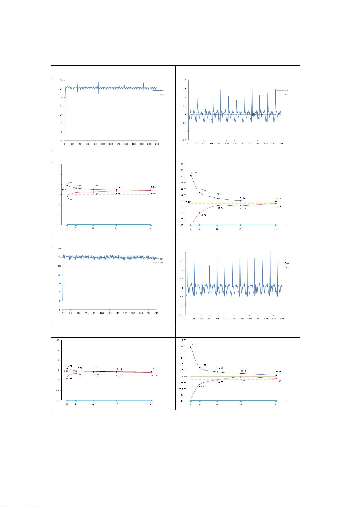
Start-up and Trumpet curves show the characteristics of the infusion pump after the
injection begins and the injection changing status after the infusion pump reaches a
normal flow rate.
The following test method is accordance with the method mentioned in chapter
201.12.1.102 of the standard IEC 60601-2-24:2012 (Please check above chapter for
further details.).
Accuracy test conditions:
Temperature: 21℃;
Relative humidity: 65%;
Infusion type:MC(20d/mL)、(B.Braun 20d/mL): 5sets each.
Infusion pump: 1 set
Sampling interval: 0.5min
Test Period: 120min
46 / 57
Page 55

Infusion Accuracy Characteristics
Administration set (IV
set) Brand
Accuracy(%)
Remaks
B.Braun
20d/mL
+4.79
Minimum rate 1ml/h,normal condition
-0.71
Intermediate rate 25ml/h,normal condition
+0.91
Intermediate rate 25ml/h,with
+13.3kpabackpressure
+0.79
Intermediate rate 25ml/h, with
-13.3kpabackpressure
-6.61
Intermediate rate 25ml/h, when the
supplycontainer below the pump
mechanismat a distance of 0.5m
Medcaptain(MC)
20d/mL
+2.57
Minimum rate 1ml/h, normal condition
+2.28
Intermediate rate 25ml/h,normal condition
-1.10
Intermediate rate 25ml/h,with
+13.3kpabackpressure
+1.00
Intermediate rate 25ml/h, with
-13.3kpabackpressure
-11.62
Intermediate rate 25ml/h,when the
supplycontainer below the pump
mechanismat a distance of 0.5m
Test Liquid: ISO 3696:1987 Class III water
Table 10-1 Accuracy test result
CAUTION:
The accuracy maybe up to -11.62% when the supplycontainer below the
pump mechanismat a distance of0.5m.
To ensure the infusion accuracy, strongly recommend that the supplycontainer is
higher than thepump mechanism.
47 / 57
Page 56
Infusion Accuracy Characteristics
Start-up curves of MC 25mL/h
Start-up curves ofMC 1mL/h
Trumpet curve of MC 25mL/h
Trumpet curve of MC 1mL/h
Start-up curves of B.Braun 25mL/h
Start-up curves ofB.Braun 1mL/h
Trumpet curve of B.Braun 25mL/h
Trumpet curve of B.Braun 1mL/h
Table 10-2 Accuracy test result
48 / 57
Page 57

Infusion Accuracy Characteristics
Infusion
rate
Occlusion
pressure level
Occlusion pressure
(mmHg)
Occlusion alarm time
(hh:mm:ss)
Bolus
(ml)
25mL/h
I
300±100
00:01:17
0.12
III
900±200
00:04:06
0.39
Infusion
rate
Occlusion
pressure level
Occlusion pressure
(mmHg)
Occlusion alarm time
(hh:mm:ss)
1mL/h
I
300±100
00:16:00
III
900±200
00:42:00
Infusion
rate
Occlusion
pressure level
Occlusion pressure
(mmHg)
Occlusion alarm time
(hh:mm:ss)
0.1mL/h
I
300±100
01:07:00
III
900±200
10:26:00
Description
Unit
Unit conversion
Pressure
kPa
1kPa=7.5mmHg
psi
1psi=51.724mmHg
bar
1bar=750mmHg
10.2 Occlusion Characteristics
The occlusion characteristics are reflected by the longest delay time to start an alarm.
The following test method is accordance with the method mentioned in chapter
201.12.4.4.104 of the standard IEC 60601-2-24:2012 (Please check above chapter for
further details.).
Occlusion test conditions:
Temperature: 21℃;
Relative humidity: 65%;
Length of the infusion tube: 1m
Table 10-3The occlusion level, alarm delay time and pill amount under the rate of 25mL/h
Table 10-4The occlusion level and alarm delay time under the rate of 1mL/h
Table 10-5The occlusion level and alarm delay time under the rate of 0.1mL/h
CAUTION:
Unit conversion list
49 / 57
Page 58

Appendix A
Guidance and manufacturer’s declaration – electromagnetic emissions
The [MP-60] is intended for use in the electromagnetic environment specified below.
The customer or the user of the [MP-60] should assure that it is used in such an
environment.
Emission test
Emission test
Emission test
RF emission
CISPR 11
Group 1
MP-60 infusion pump only use
radio-frequency power while
operating its internal functions,
therefore, the radio-frequency
emission is much low and has little
interference to the electronic devices
nearby.
Radio-frequency
emission
CISPR 11
Class A
The MP-60 infusion pump can be used in
any building including civil residence.
Harmonic emission
IEC61000-3-2
Class A
Voltage fluctuation
and flashing
IEC 61000-3-3
Complies
Appendix A Electron Magnetic Compatibility (EMC)
The MP-60 Infusion Pump conforms to EMC standard EN 60601-1-2.
50 / 57
Page 59

Appendix A
Guidance and manufacturer’s declaration – electromagnetic immunity
The [MP-60] is intended for use in the electromagnetic environment specified below. The customer
or the user of the [MP-60] should assure that it is used in such an environment.
IMMUNITYtest
IEC60601test level
Compliance level
Electromagnetic environment
–guidance
Electrostatic
discharge
(ESD)
IEC 61000-4-2
±8 kV contact
discharge
±15 kV air discharge
±8 kV contact
discharge
±15 kV air
discharge
Floors should be wood,
concrete or ceramic tile. If
floors are covered with
synthetic material, the relative
humidity should be at least
30 %.
Electrical fast
transient
(EFT)
IEC61000-4-4
±2 kV power cable
±1 kV I/O cable
±2 kV power cable
Mains power quality should
be that of a typical
commercial or hospital
environment.
Surge
IEC 61000-4-5
±1 kV difference mode
±2 kV common mode
±1 kV difference
mode
±2 kV common
mode
The voltage
dropping, short
interruption and
voltage change
IEC 61000-4-11
<5% UT(dropping>
95% UT)0.5 period
40% UT( dropping
60% UT)5 period
70% UT(dropping 30%
UT)25 period
<5% UT(dropping>
95% UT)5seconds
<5% UT(dropping
>95% UT)0.5
period
40% UT( dropping
60% UT)5 period
70% UT(dropping
30% UT)25 period
<5% UT(dropping
>95% U
T
)
5seconds
Mains power quality should
be that of a typical
commercial or hospital
environment. If the user of the
[MP-60] requires
continued operation during
power mains interruptions, it
is recommended that the
[MP-60] be powered from an
uninterruptible power supply
or a battery..
Power
3 A/m
3 A/m
Power frequency magnetic
51 / 57
Page 60

Appendix A
frequency
magnetic fields
(50/60Hz)
IEC 61000-4-8
fields should be at levels
characteristic of a typical
location in a typical
commercial or hospital
environment
NOTE UTis the a.c mains voltage prior to application of the test level.
52 / 57
Page 61
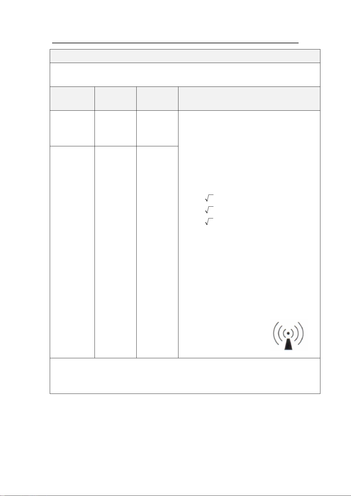
Appendix A
Guidance and manufacturer’s declaration – electromagnetic immunity
The [MP-60] is intended for use in the electromagnetic environment specified below. The
customer or the user of the [MP-60] should assure that it is used in such an environment.
Immunity
Test
IEC 60601
test level
Compliance
level
Electromagnetic environment –guidance
Conducted
RF
IEC61000-4-6
3 Vrms
150k~
80MHz
3 Vrms
Portable and mobile RF communications
equipment should be used no closer to any part
of the [MP-60], including cables, than the
recommended separation distance calculated
from the equation applicable to the frequency of
the transmitter.
Recommended separation distance:
Pd
2.1
Pd
2.1
80M~800MHz
Pd
3.2
800M~2.5GHz
where Pis the maximum output power rating of
the transmitter in watts (W) according to the
transmitter manufacturer and dis the
recommended separation distance in metres (m).
Field strengths from fixed RF transmitters, as
determined by an electromagnetic site survey a,
should be less than the compliance level in each
frequency rangeb.
Interference may occur in the
vicinity of equipment marked
with the following symbol:
Radiated RF
IEC61000-4-3
3V/m
80M~
2.5GHz
3 V/m
NOTE 1 At 80 MHz and 800 MHz, the higher frequency range applies.
NOTE 2 These guidelines may not apply in all situations. Electromagnetic propagation is
affected by absorption and reflection from structures, objects and people.
53 / 57
Page 62

Appendix A
a
Field strengths from fixed transmitters, such as base stations for radio (cellular/cordless)
telephones and land mobile radios, amateur radio, AM and FM radio broadcast and TV broadcast
cannot be predicted theoretically with accuracy. To assess the electromagnetic environment
dueto fixed RF transmitters, an electromagnetic site survey should be considered. If the
measured field strength in the location in which the [MP-60] is used exceeds the applicable RF
compliance level above, the [MP-60] should be observed to verify normal operation. If abnormal
performance is observed, additional measures may be necessary, such as re-orienting or
relocating the [MP-60].
b
Over the frequency range 150 kHz to 80 MHz, field strengths should be less than [3] V/m.
54 / 57
Page 63
Appendix A
Recommended separation distances between portable and mobile RF communications equipment
and the [MP-60]
The [MP-60] is intended for use in an electromagnetic environment in which radiated RF
disturbances are controlled. The customer or the user of the [MP-60] can help prevent
electromagnetic interference by maintaining a minimum distance between portable and mobile RF
communications equipment (transmitters) and the [MP-60] as recommended below, according to
the maximum output power of the communications equipment.
Rated maximum
output power of
transmitter (W)
Separation distance according to frequency of transmitter(m).
150k~80MHz
Pd 2.1
80M~800MHz
Pd 2.1
800M~2.5GHz
Pd 3.2
0.01
0.12
0.12
0.23
0.1
0.38
0.38
0.73
1
1.2
1.2
2.3
10
3.8
3.8
7.3
100
12
12
23
For transmitters rated at a maximum output power not listed above, the recommended separation
distance din metres (m) can be estimated using the equation applicable to the frequency of the
transmitter, where Pis the maximum output power rating of the transmitter in watts (W) according to
the transmitter manufacturer.
NOTE 1 At 80 MHz and 800 MHz, the separation distance for the higher frequency range applies.
NOTE 2 These guidelines may not apply inall situations. Electromagnetic propagation is affected
by absorption and reflection from structures, objects and people.
55 / 57
Page 64

Appendix B
Parameters setting
The default factory setting
KVO flow rate
1ml/h
Pressure unit
mmHg
Occlusion pressure
P2(middle level)
Near end
3min
Built-in consumable brand
MC(20d/ml)、B.Braun(20d/ml)
System time and date
The default factory setting
Time
00:00
Date
2014-1-1
Time form
24 hours
Date form
Year-month-day
Appendix B The Default Factory Settings
This chapter lists some default factory settings of infusion pump. Users can not
modify the default factory settings, but if necessary, they can recover the infusion pump to
the default factory settings state.
Parameters
System time
56 / 57
Page 65

Appendix C
Description
Plumbum
Pb
Mercury
Hg
Cadmium
Cd
Chromium
VI Cr(VI)
Polybromi
nated
biphenyls
PBB
polybrominat
ed diphenyl
ethers
PBDE
pump shell
○ ○ ○ ○ ○
○
key and
cover
○ ○ ○ ○ ○
○
label
○ ○ ○ ○ ○
○
display
× × × × × × hardware
○ ○ ○ × ○
○
connection
wire
○ ○ ○ ○ ○
○
PCBA
× ○ ○ ○ ○
○
packing
material
○ ○ ○ ○ ×
×
battery
× × × × × × accessory
× ○ ○ ○ ○
○
remark:
“○” shows that the content of this toxic and harmful substance in all homogeneous
materials are under the regulated limitation requirement of SJ/T11363-2006.
“×”shows that he content of this toxic and harmful substance in one homogeneous
materials is over the regulated limitation requirement of SJ/T11363-2006.
Appendix CToxic and Hazardous Substances or Elements
57 / 57
Page 66

Precautions for Use
MEDCAPTAIN MEDICAL TECHNOLOGY CO., LTD.
Registration address: 12th Floor, Baiwang Research Building, No.5158 Shahe West Road,
Xili, Nanshan District, Shenzhen, P.R.China
Production address: 1-4 Floor,11th Building,Nangang Industrial Park, Songbai Road, Xili,
Nanshan District, Shenzhen, P.R.China
After-sales service address: 12th Floor, Baiwang Research Building, No.5158 Shahe
West Road, Xili, Nanshan District, Shenzhen, P.R.China
EU- Representative name: WellKang Ltd
EU- Representative address: Suite B, 29 Harley Street LONDONW1G 9QR, England,
United Kingdom
Telephone: +86-755-26953369 0123
Fax: +86-755-26001651
Postal code: 518055
Website: http://www.medcaptain.com
E-mail: [email protected]
Copyright of 2016 Medcaptain Medical Technology Co., Ltd. (V2.2)
 Loading...