

Page 1

Technical Manual for the
Fire Alarm Call Point - SM87 PBL
Please note that every care has been taken to ensure the accuracy of our technical manual. We do not, however, accept
responsibility for damage, loss or expense resulting from any error or omission. We reserve the right to make alterations
in line with technical advances and industry standards.
© MEDC 2014 11/14
Page 2

1. INTRODUCTION
These fire alarm call point units have been designed for use in harsh environmental conditions.
2. INSTALLATION
General
When installing and operating explosion-protected electrical equipment, requirements for selection, installation and operation should be referred to eg. IEC
60079-14 worldwide and the ‘National Electrical Code’ in North America.
Additional national and/or local requirements may apply.
Ensure that all nuts, bolts and fixings are secure.
Ensure that only the correct UL listed stopping plugs are used to blank off unused
gland entry points and that the NEMA/IP rating of the unit is maintained.
The SM87PBL is mounted via 4 x Ø 0.354” (9mm) fixing holes in the base.
The fixing holes have been designed to accept an M8 caphead screw or bolt.
MEDC recommend the use of stainless steel screws.
Cable Termination
Unscrew and remove the 4 off screws holding the cover assembly to the base.
Keep in a safe, accessible location.
Twist the cover assembly gently clockwise and anti-clockwise, whilst pulling it
away from the base. Remove to gain access to the interior of the base.
Cable termination should be in accordance with specifications applying to the
application. MEDC recommend that all cables and cores should be fully
identified.
Ensure that only correct UL Listed cable glands are used and that the assembly is
shrouded and correctly earthed.
All cable glands should be of an equivalent NEMA/IP rating to that of the call
point and integrated with the unit such that this rating is maintained.
The internal earth terminal (where fitted), must be used for the equipment grounding connection and the external terminal is for a supplementary bonding connection where local codes or authorities permit or require such a connection.
Once termination is complete, carefully push the cover assembly back onto the
base, avoiding damage to the mating surfaces. Replace the 4 off screws into the
holes in the cover assembly and tighten evenly, to ensure maintenance of the
required gap between the cover & base.
11/14 © MEDC 2014
Page 3
3. OPERATION
The call point is operated by lifting the flap on the front of the unit, then depressing the stainless steel actuator underneath. The actuator remains latched in an
operated position. To reset the call point, the key (provided with the unit) is
inserted into the slot provided in the actuator front face and pulled back to the
initial position. The key is then removed and the flap lowered.
4. MAINTENANCE
During the working life of the call point, little or no maintenance is required.
However, if abnormal or unusual environmental conditions occur due to plant
damage or accident etc., then visual inspection is recommended.
If a fault should occur, it is recommended that the unit be returned to MEDC for
repair. All parts are replaceable.
If you have acquired a significant quantity of units, it is recommended that spares
are also made available. Please discuss your requirements with the Technical
Sales Engineers at MEDC.
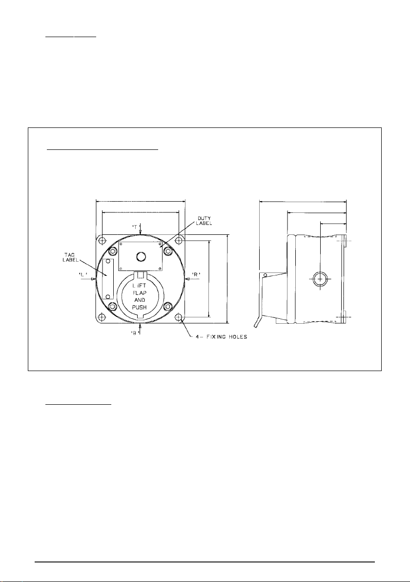
GENERAL ARRANGEMENT
ALL DIMENSIONS IN INCHES AND MILLIMETERS
43/4" / 121mm
41/8" / 105mm
4
1
/8" / 105mm
4
3
/4" / 121mm
3
/8" / 9mm DIA.
53/16"
/ 132mm
3
7
/16" / 87mm
1
7
/16"
37mm
© MEDC 2014 11/14
Page 4

CERTIFICATION/APPROVALS
Please refer to marking on the unit for specific approval details
● UL listed for use in Class 1, Division 1, Groups C & D
USA (USL) Class 1, Zone 1, Groups IIA & IIB
● UL Standards UL1203 & UL864
● Suitable for hazardous location fire-alarm applications
CERTIFIED TEMPERATURE
–55°C to +55°C
–67°F to +131°F
6.
7.
5. WARNING STATEMENTS
i) To reduce the risk of ignition of hazardous atmospheres, disconnect the
equipment from the supply circuit before opening. Keep assembly tightly
closed when in operation
ii) To reduce the risk of ignition of hazardous atmospheres, conduit runs must
have a sealing fitting connection within 18 inches of the enclosure
Avertissements
i) Afin de réduire le risque d'allumage et d'incendie dans des atmosphères
dangereuses, déconnectez l'équipement du circuit d'alimentation avant de
procéder à son ouverture. Maintenez l'appareil fermé hermétiquement lors
de son utilisation
ii) Afin de réduire le risque d'allumage et d'incendie dans des atmosphères
dangereuses, les courses de conduits doivent être dotées d'un raccord
d'étanchéité situé à 18 pouces ou moins du boîtier
MEDC Ltd, Unit B, Sutton Parkway, Oddicroft Lane, Sutton in Ashfield, United Kingdom NG17 5FB
Tel: +44 (0)1623 444444 Fax: +44 (0)1623 444531
Email: MEDCSales@Eaton.com MEDCOrders@Eaton.com
Web: www.medc.com
MEDC Stock No:
TM103-ISS.B
11/14 © MEDC 2014
 Loading...