

Medal Sports WM1324805 User Manual [es, en]
Please contact us before returning the product to the store.
Toll Free: 877-472-4296
Por favor póngase en contacto con nosotros antes de
devolver el producto a la tienda.
Número telefónico gratis: 877-472-4296
INSTRUCCIONES DE ARMADO
MODEL/MODELO: 24805

LIMITED 90 DAYS WARRANTY
This product is covered by a limited warranty that is effective for 90 days from the
date of purchase. If, during the limited warranty period, a part is found to be defective or breaks, we will offer replacement part at no cost to you, the customer. The
only exceptions to the warranty include main frames, table tops, playing surfaces,
batteries or tools.
The above warranty will not apply in cases of damages due to improper usage,
alteration, misuse, abuse, accidental damage or neglect.
This Limited Warranty gives you specific legal rights and you may also have other
rights which vary from one State (province) to another.
“PLEASE SAVE THESE INSTRUCTIONS
AND PURCHASE RECEIPT!”
A PURCHASE RECEIPT (or other proof of purchase date) will be required before
any warranty service is initiated. All requests for warranty service, please feel free
to contact our Consumer Service Department at :
TOLL FREE: 877-472-4296
WEBSITE: www.themdsports.com
*Please be aware of your product’s Limited Warranty for the return/refund policy
from the store, We, at Medal Sports, can not handle the product which is out of
product’s limited warranty since we only provide available parts.
*Please note that all damaged table tops/playing surfaces need to be returned to
the store.
PLEASE CONTACT US BEFORE RETURNING
THE PRODUCT TO THE STORE.
Attention: Since you build all tables upside down, please inspect table tops or
playing surfaces right away before putting together.
THANK YOU VERY MUCH!
1
WARNING:
!
WARNING:
!
Adult Assembly Required.
2
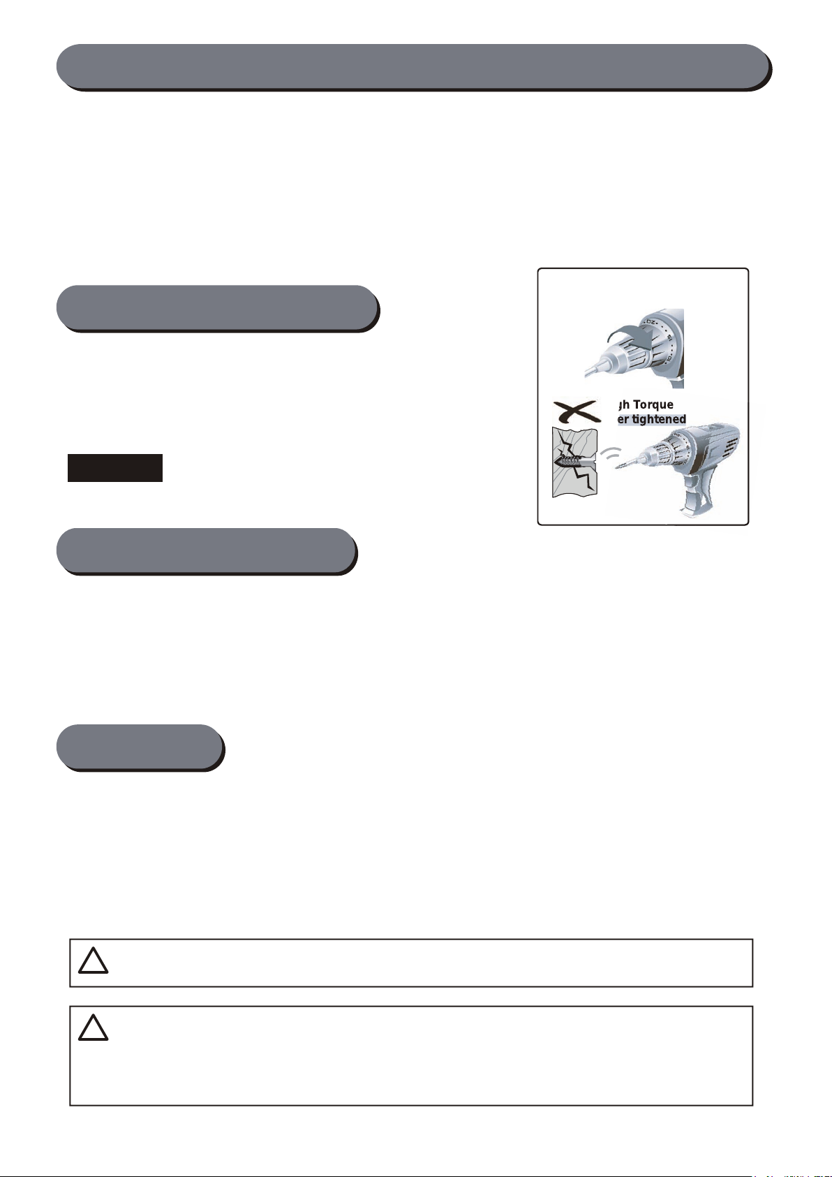
Power Tools
- Set Low Torque
High Torque
over tightened
CAUTION !
TOOLS REQUIRED:
ASSEMBLY TIPS:
IMPORTANT NOTICE! Please contact us before returning the product to the store.
Please Keep Your Instructions! Your Model number is necessary should you need to contact
us. Please read through this instruction manual book to familiarize yourself with all parts and
assembly steps. Kindly refer to the parts list below and be sure that all parts have been
included.
Although we are dedicated to giving our customers the best product possible, a question may
arise or parts may be missing. If you are missing parts, or, if you have any questions, please
contact our fast and friendly service centre on:
877-472-4296
Phillips Screwdriver - Not Included
Standard (Flat Head Screwdriver) - Not Included
Allen Key - Included
Electric Screwdrivers may be helpful during
assembly; however, please set a low torque
and use extreme caution.
1 - Please read the instructions carefully, and follow all assembly, operation or safety instructions
properly in order to avoid damage or injury. For the assembly, at least two adults are required.
2 - Some figures or drawings may not look exactly like your product. Please read and understand
the text before beginning each assembly step.
1 - This product is intended for INDOOR use only.
2 - Please Do Not sit, climb or lean on the game table.
3 - Please Do Not drag the table when moving it in order to avoid the damaged on the legs.
4 - Please only use spray furniture polish to clean the exterior surfaces on the game table.
5 - This is not a child's toy, adult supervision is required for children playing this game.
NOTICE!
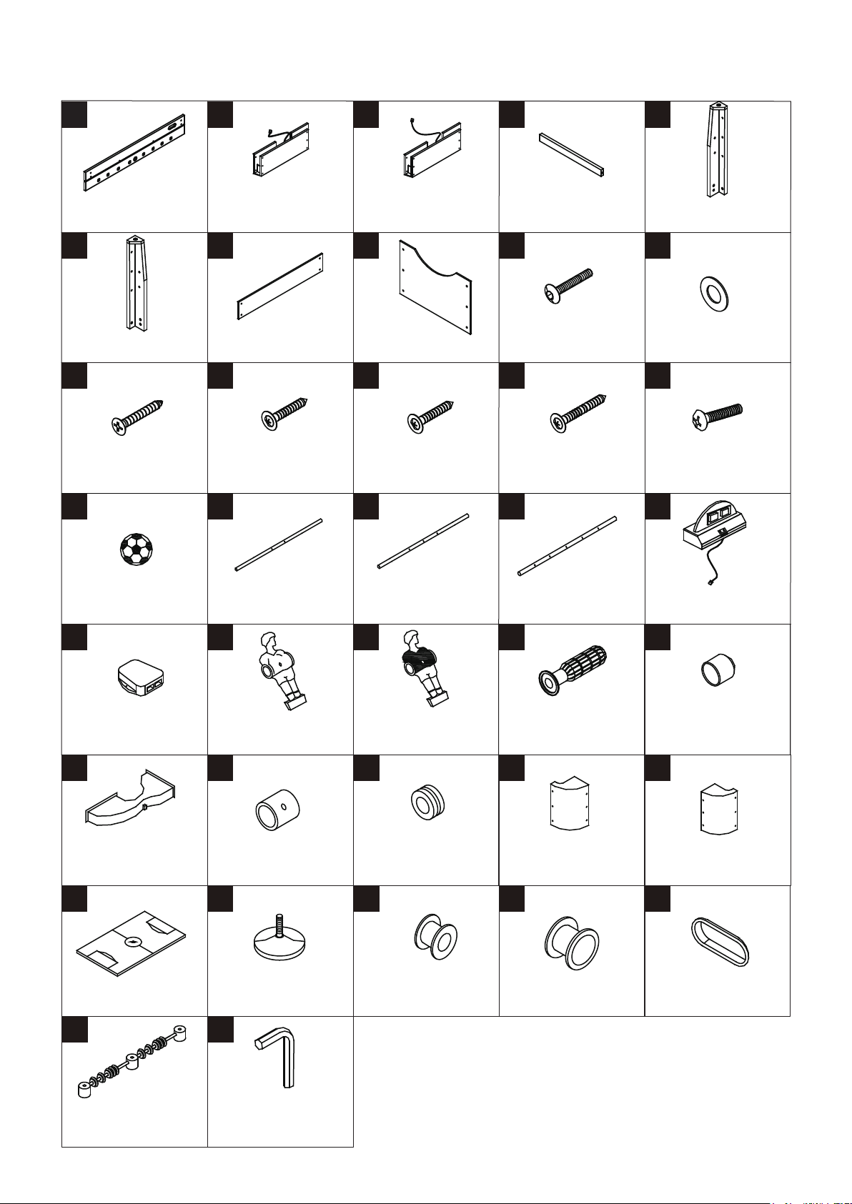
24805 PARTS LIST
1 2 3 4 5
Side Apron
2 Pieces
End Apron With Short
Sensor Wire
1 Piece
End Apron With Long
Sensor Wire
1 Piece
Support Brace
2 Pieces
6 7 8 9 10
Right Leg
2 Pieces
Side Leg Brace
2 Pieces
End Leg Brace
2 Pieces
6X30MM Leg Bolt
12 Pieces
11 12 13 14 15
3.5X25mm
Flat Head Screw
3 Pieces
3.5X12mm
Washer Head Screw
48 Pieces
3.5X10.5mm
Washer Head Screw
14 Pieces
3.5X35mm
Washer Head Screw
12 Pieces
16 17 18 19 20
21
Soccer Ball
2 Pieces
2-Hole Rod
2 Pieces
22
23
3-Hole Rod
4 Pieces
24
5-Hole Rod
2 Pieces
25
Left Leg
2 Pieces
18X6.5MM Washer
12 Pieces
3.5X7mm Bolt
52 Pieces
ElectronicL Scorer
With Wire
1 Piece
Connect Box
1 Piece
26
Goal Box
2 Pieces
31
Soccer Playfield
1 Piece
36
Slide Scorer
1 Piece
Player - Blue
11 Pieces
Player - Yellow
11 Pieces
27 28
Stop Ring
4 Pieces
32 33 34
Leg Leveler
4 Pieces
Rubber Bumper
16 Pieces
Pre-installed
Plastic Rod Bushing
16 Pieces
37
Allen Key
1 Piece
Handle
8 Pieces
Left Apron Corner
2 Pieces
Plastic Ball Entry Rim
2 Pieces
Rod End Cap
8 Pieces
3029
Right Apron Corner
2 Pieces
35
Pre-installedPre-installed
Ball Return Cover
2 Pieces
3

ASSEMBLY INSTRUCTIONS
1. Find a clean, level place to begin the assembly of your Soccer Table. The table will be assembled upside down
and then turned over on its legs once the assembly completed. This game table is heavy, and turning it over will
require at least two strong adults.
2. Remove all the parts from the box and verify that you have all of the listed parts as shown on the parts list page.
Carefully cut or tear the four corners of the box so that the bottom of the box can be used as your work surface.
FIG.1
3. Attach one End Apron (#3) to the Side Aprons (#1) using four Screws (#14). Note: Do not tighten the Screws
at this step.
4. Slide the Playfield (#31), with the graphics facing down, into the grooves of the Side and End Aprons (#1 & #3).
FIG. 1
31
34
35
1
14
3
4
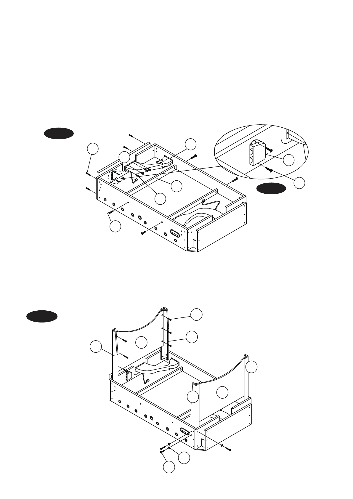
FIG.2
5. Attach the other End Aprons (#2) to the Side Aprons (#1) using four Screws (#14), and make sure that the
Playfield is in the grooves of the Side and End Aprons. Now go back and tighten all the connections.
6. Place the Support Braces (#4) on the Playfield (#3) and then attach them to the Side Aprons (#1) using two
Screws (#14) per Support Brace.
7. Attach the Goal Boxes (#26) to the End Aprons (#2 & #3) using four Screws (#13) and to the Side Aprons (#1)
usign three Screws (#13) per Goal Box.
8. Attach the Connect box (#21) to one End Apron (#2) using two Screws (#12). The Connect Box should be
assembled near the End Apron with Short Sensor Wire (#2). See FIG.2A.
FIG. 2
4
26
21
12
FIG. 2A
14
2
13
14
FIG.3
9. Attach the Left and Right Legs (#5 & #6) to the Side and End Aprons using three Bolts (#9) and three W ashers (#10)
per Leg.
10. Attach the End Leg Braces (#8) to the Legs using six Screws (#12) per End Leg Brace.
FIG. 3
12
8
6
5
5
8
6
10
9
5
 Loading...