

Page 1
English
Manual of use and maintenance
//
Page 2

2
Piezosurgery // - manual of use and maintenance
3
Piezosurgery // - manual of use and maintenance
00.0 Introduction
00.1 Foreword
Before proceeding with the installation, use, maintenance or any other activities on the
equipment please read this manual carefully.
Always keep this manual within easy reach.
Important: To avoid causing personal injuries or damage to property, read all the points concerning
“Safety requirements” contained in this manual with particular attention.
Depending on the level of risk involved, safety requirements are classed under the following indications:
�
DANGER (always referred to personal injury)
�
WARNING (referred to possible damage to property)
The purpose of this manual is to ensure that operators are aware of the safety requirements, of the
installation procedures and of the instructions for correct use and maintenance of the apparatus.
The user is not authorised to tamper with the equipment under any circumstances.
If any problems are encountered, please contact a Mectron Service Centre.
Any attempts on the part of the user or any unauthorised personnel to tamper with or alter the
apparatus will invalidate the warranty and release the Manufacturers from any liability in respect of
any harm or damage to persons or property.
The information and illustrations contained in this manual are up-dated to the date of publication
indicated on the last page.
MECTRON are committed to continuous up-dating of their products, which may entail changes to
components of the equipment. If there are any discrepancies between the descriptions contained
in this manual and your equipment, please contact your dealer or the MECTRON After-Sale service
for explanations.
Using this manual for purposes other than those relating to the installation, use and maintenance of
the equipment is strictly prohibited.
00.2 Description of the Device
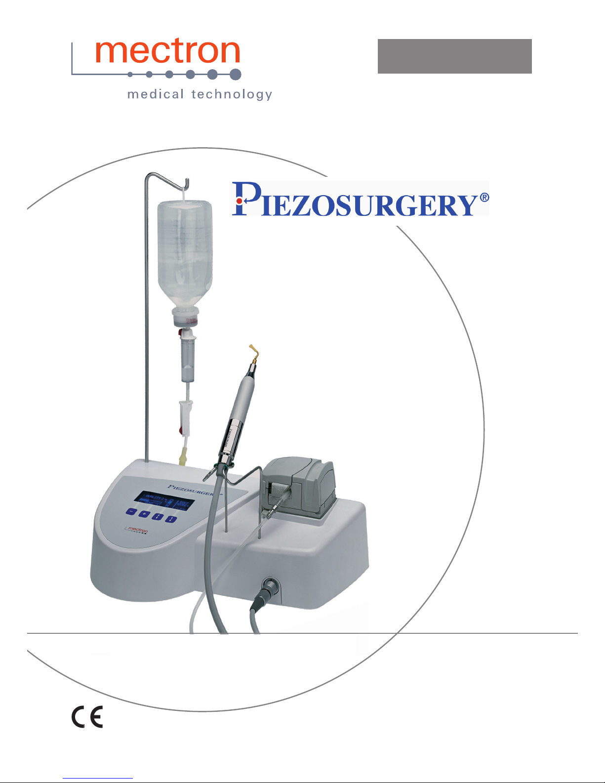
Thanks to its controlled three-dimensional ultrasound oscillations, the original Piezosurgery technique rings in a new age for osteotomy and osteoplasty in Implantology, Periodontology, Endodontics and Orthodontic Surgery. Its main features are:
- Micrometric cutting: Maximum surgical precision and intra-operative sensibility;
- Selective cutting: Maximum safety for the soft tissues;
- Cavitation effect: Maximum intra-operative visibility (bloodless eld).
The equipment has an automatic tuning circuit that offsets wear of the inserts, thus ensuring work
in constant conditions of maximum efciency.
Summary
00.0 Introduction ........................................................................................................................ .....3
00.1 Foreword .................................................................................................................... .....3
00.2 Description of the Device ............................................................................................ .....3
00.3 Intended Use .............................................................................................................. .....4
00.4 Safety requirements .................................................................................................. .....4
01.0 Identication data .............................................................................................................. .....6
01.1 Identication data ...................................................................................................... .....6
01.2 Data plate of the device .............................................................................................. .....6
01.3 Data plate of the scaler handpiece ............................................................................. .....6
02.0 Testing ................................................................................................................................ .....7
02.1 Testing of the equipment ............................................................................................ .....7
03.0 Delivery............................................................................................................................... .....7
03.1 Delivery of the apparatus ............................................................................................ .....7
03.2 List of material included in the supply ......................................................................... .....8
04.0 Installation.......................................................................................................................... ...10
04.1 Safety requirements during Installation ...................................................................... ...10
04.2 Initial installation ......................................................................................................... ...10
04.3 Connecting the Accessories ....................................................................................... ...11
05.0 Use ...................................................................................................................................... ...13
05.1 Controls ...................................................................................................................... ...13
05.2 Switching the device ON and OFF ............................................................................ ...13
05.3 Description of the display and functions .................................................................... ...14
05.4 Safety requirements during use ................................................................................. ...16
05.5 Protection systems and alarms ................................................................................. ...17
05.6 Instructions for use .................................................................................................... ...18
05.7 Permissible settings on the basis of the type of insert ................................................ ...19
05.8 Rules for keeping the device in proper working order ................................................ ...19
06.0 Cleaning and sterilisation ................................................................................................. ...20
06.1 CLEAN function - Cleaning of the liquid circuit ........................................................... ...20
06.2 Cleaning and disinfecting the casing of the device ..................................................... ...20
06.3 Sterilisation procedure ............................................................................................... ...21
06.4 Cleaning and autoclave sterilisation of the handpiece ............................................... ...21
06.5 Cleaning and autoclave sterilisation of the inserts ..................................................... ...22
06.6 Cleaning and autoclave sterilisation of the wrench for tightening the inserts ............. ...23
06.7 Autoclave sterilising of the tube of the peristaltic pump .............................................. ...23
06.8 Autoclave sterilising of the tting between the cord and the tube of the peristaltic pump . ...24
07.0 Regular maintenance ....................................................................................................... ...24
07.1 Shelf Storage .............................................................................................................. ...24
07.2 Power-supply cable ................................................................................................... ...24
08.0 Replacement of the fuses ................................................................................................. ...25
09.0 Disposal procedures and precautions ............................................................................ ...25
10.0 The inserts ......................................................................................................................... ...26
11.0 Symbols .............................................................................................................................. ...26
12.0 Troubleshooting ............................................................................................................... ...27
13.0 Technical data .................................................................................................................... ...30
13.1 Electromagnetic compatibility EN 60601-1-2 ............................................................... ...31
14.0 Guarantee ........................................................................................................................... ...35
Page 3

4
Piezosurgery // - manual of use and maintenance
5
Piezosurgery // - manual of use and maintenance
00.3 Intended Use
The Piezosurgery is a piezoelectric device for bone surgery that enables osteotomy and osteoplasty techniques to be applied to in almost any anatomical situation. This equipment can be used
in the following elds:
- Oral Surgery:
Extraction - Apicectomy - Cystectomy - Osteogenic distraction.
- Implantology:
Bone window osteotomy - Crest expansion - Bone fragment removal - Monocortical bone re-
moval - Osteoplasty - Final preparation of the implant site - Extraction for immediate implantation - Elevation of Schneider’s membrane.
- Periodontal Surgery:
Osteotomy and osteoplasty techniques - Removal of bone tissues in regeneration surgery -
Root debridement - Root planing.
- Surgical Orthodontics:
Exposure or extraction of embedded teeth - Orthodontic corticotomy.
This equipment may be used only in a dentist’s surgery or out-patient’s department where there are
no inammable gases (anaesthetic mixtures, oxygen, etc.).
00.4 Safety requirements
Mectron will not accept any liability for direct or incidental personal injury or damage to property in
the following cases:
1 If the equipment is used for purposes other than that for which it is intended.
2 If the equipment is not used in accordance with all the instructions and requirements described
in this manual.
3 If the wiring system in the room where the equipment is used does not comply with the applica-
ble standards and appropriate requirements.
4 If any assembly operations, extensions, settings, alterations or repairs have been carried out
by personnel not authorised by Mectron.
5 If the environmental conditions in which the device is kept and stored do not comply with the
requirements indicated in the chapter on technical specications.
�
DANGER: Qualied and specialised personnel.
This equipment may be used only by specialised and suitably trained personnel such as surgeons.
If correctly used, this equipment does not give rise to side effects. Improper use, on the other hand,
will give rise to transmission of heat to the tissues.
�
DANGER: Intended use.
Use the equipment solely for the purpose for which it is intended (see point “00.3”). Failure to
comply with this requirement could lead to serious harm to the patient and/or to the operator and/or
damage to/failure of the equipment.
�
DANGER: Contraindications.
Do not use the Piezosurgery on patients with pace-makers or other implantable electronic devices.
The same requirement applies also to the operator.
�
DANGER: Contraindications.
An electrosurgical knife could interfere with correct functioning of the device.
�
DANGER: Cleaning, disinfection and sterilisation of new or repaired products.
All new or repaired products are delivered in non sterile conditions. Before being used for treatments, all new or repaired products should be cleaned, disinfected and sterilised following the
instructions provided under point “06.0” strictly.
�
DANGER: Infection control.
In order to ensure maximum safety for both the patient and the operator, use only accessories that
have been cleaned, disinfected and sterilised. Follow the instructions provided under point “06.0”
closely.
�
DANGER: Use only original Mectron accessories and spare parts.
�
DANGER: Check the condition of the device before treatment.
Always make sure that there is no water under the apparatus. Before each treatment always check
that the equipment is in proper working order and that the accessories are efcient. Do not carry
out the treatment if any problems are encountered in operating the device. If the problems concern
the equipment contact an authorised technical service centre.
�
DANGER: Breakage and wear of the Inserts.
The high-frequency vibrations and wear may, very occasionally, lead to breakage of the insert.
Inserts of which the shape has been changed or which are otherwise damaged are liable to break
during use. Any such inserts should denitely not be used. It is necessary to instruct the patient to
breathe through his nose during the treatment in order to avoid ingestion of the broken off fragment
of the insert.
�
DANGER: Do not install the equipment anywhere where there is a risk of explosions.
The equipment cannot function in places where there is an inammable atmosphere (anaesthetic
mixtures, oxygen, etc.).
�
DANGER: Personal injury.
The footswitch of the Piezosurgery must not be activated with the door of the peristaltic pump open
(Fig.4 - Ref.B). Moving parts could injure the operator.
�
WARNING: Contraindication.
Do not carry out this treatment on metal or ceramic prosthetic artefacts. The ultrasonic vibrations
could lead to decementing of such artefacts.
�
WARNING: Contraindication.
After autoclave sterilising of the handpiece, wait for it to cool down completely before using it.
Page 4
6
Piezosurgery // - manual of use and maintenance
7
Piezosurgery // - manual of use and maintenance
01.0 Identication data
01.1 Identication data
An exact description of the model including the serial number of the equipment will make it easier
for our After-Sale Service to respond quickly and efciently to your queries.
Always provide the above information whenever you contact a Mectron Service Centre.
01.2 Data plate of the device
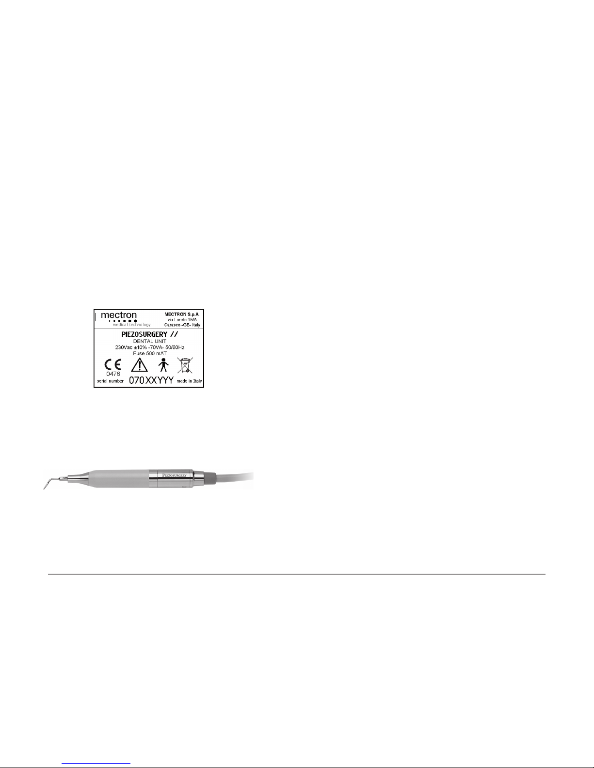
Each device has its own data plate (Fig.1), on which its technical specications and serial number
are indicated. The data plate is on the rear of the device. The remaining data are included in this
manual (see Section “13.0”).
01.3 Data plate of the scaler handpiece
The serial number of this Piezosurgery handpiece is engraved on the ringnut (Fig.2 - Ref.A).
02.0 Testing
02.1 Testing of the equipment
All equipment manufactured by MECTRON is thoroughly checked and tested, including all components.
During the testing procedure the components are subjected to a number of work cycles.
The tests highlight any malfunctioning due to faulty components.
This procedure ensures proper functioning and reliability of all components.
03.0 Delivery
03.1 Delivery of the apparatus
The equipment contains electronic components that may be damaged by impacts even inside the
packaging. Special care must therefore be taken for both transport and storage.
In order to avoid crushing, do not place cartons on top of one.
All material shipped by MECTRON is checked at the time of shipment.
The equipment is delivered properly protected and packaged.
At the time of receipt of the equipment check it for possible transport damage. If any damage is
found, make a complaint to the carrier.
Fig. 2
A
Fig. 1
Page 5
8
Piezosurgery // - manual of use and maintenance
9
Piezosurgery // - manual of use and maintenance
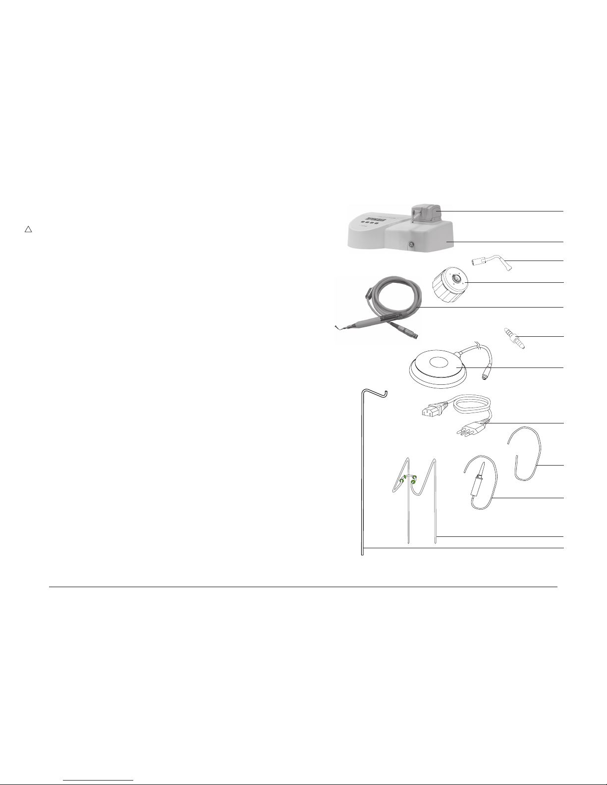
03.2 List of material included in the supply
The material included in the supply may vary in case of promotional campaigns.
�
WARNING: Handpiece and cord can’t be detached.
“Starter” conguration
1 Casing of the device (Fig.3 - Ref.B).
1 Piezosurgery handpiece complete with cord (Fig.3 - Ref.E).
1 K5 torque wrench (Fig.3 - Ref.D).
1 Footswitch with cable and plug (Fig.3 - Ref.G).
1 Connection for the cord and tube of the peristaltic pump (Fig.3 - Ref.F).
2 Drip system (Fig.3 - Ref.L).
1 Power-supply cable (Fig.3 - Ref.H).
8 Tube for the Piezosurgery peristaltic pump (Fig.3 - Ref.I).
1 Rod for supporting the bag (Fig.3 - Ref.N).
1 Support for the Piezosurgery handpiece (Fig.3 - Ref.M).
5 Inserts (Fig.3 - Ref.C).
“Professional” conguration
1 Casing of the device (Fig.3 - Ref.B).
2 Piezosurgery handpieces complete with cords (Fig.3 - Ref.E).
2 K5 torque wrenches (Fig.3 - Ref.D).
1 Footswitch with cable and plug (Fig.3 - Ref.G).
2 Connections for the cord and tube of the peristaltic pump (Fig.3 - Ref.F).
2 Drip system (Fig.3 - Ref.L).
1 Power-supply cable (Fig.3 - Ref.H).
8 Tube for the Piezosurgery peristaltic pump (Fig.3 - Ref.I).
1 Rod for supporting the bag (Fig.3 - Ref.N).
1 Support for the Piezosurgery handpiece (Fig.3 - Ref.M).
10 Inserts (Fig.3 - Ref.C).
B
A
C
D
E
F
G
N
Fig. 3
H
M
L
I
Page 6
10
Piezosurgery // - manual of use and maintenance
11
Piezosurgery // - manual of use and maintenance
Fig. 4
04.0 Installation
04.1 Safety requirements during Installation
�
DANGER: The wiring system of the premises where the apparatus is installed and used must
comply with the applicable standards and the relevant electrical safety requirements.
�
DANGER: Do not install the apparatus in places where there is a risk of explosion. The ap-
paratus may not be used in areas where there are inammable atmospheres (anaesthetic mixtures,
oxygen, etc.).
�
DANGER: Install the apparatus in a place where it will be protected from blows and from ac-
cidental sprays of water or other liquids.
�
DANGER: Do not install the device on or in the vicinity of sources of heat. Install it in such a
way that there is an adequate circulation of air around it. Leave sufcient free space around it, in
particular with reference to the fan on the rear (Fig.5 - Ref.G).
�
DANGER: Personal injury.
The footswitch of the Piezosurgery must not be activated when the door of the peristaltic pump is
open (Fig.4 - Ref.B). Moving parts could cause personal injury of the operator.
�
WARNING: Do not expose the apparatus to direct sunlight or to sources of UV light.
�
WARNING: The apparatus is transportable, however it must be handled with care when it is
moved. Position the pedal on the oor in such a way that it can only be activated intentionally by
the operator.
�
WARNING: Before connecting the cord to the device, make sure that the electrical contacts are
perfectly dry. If necessary, dry them with the air syringe.
04.2 Initial installation
To ensure perfect operation of the equipment, it is installed by technical personnel authorised by
Mectron. The equipment will be installed in a suitable and handy place for it to be used, and is
enabled by entering an activating password.
The activating password is given to the technician responsible for installation and is not indicated
inside the package containing the device. The purpose of this is to ensure immediate traceability of
the device, as required according to current legislation.
The technician must:
- Install the device in a suitable place;
- Explain the main aspects of correct installation to the user;
- Fill in the installation form, including the purchaser’s data;
- Send the installation form to Mectron to ensure traceability and activation of the warranty;
- Enter the activating password to enable the device.
A
C
D
E
B
04.3 Connecting the Accessories
The accessories listed below have to be connected to the Piezosurgery device:
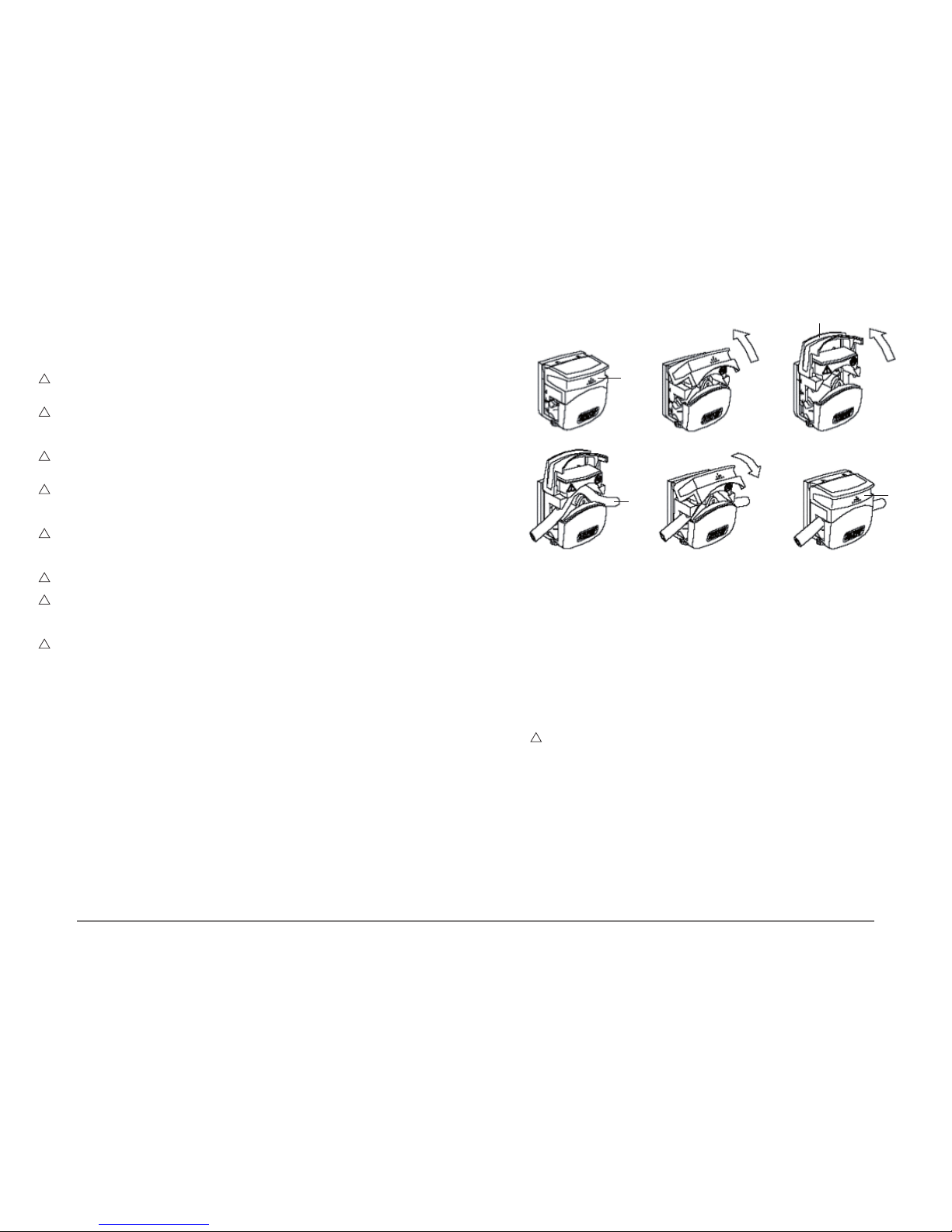
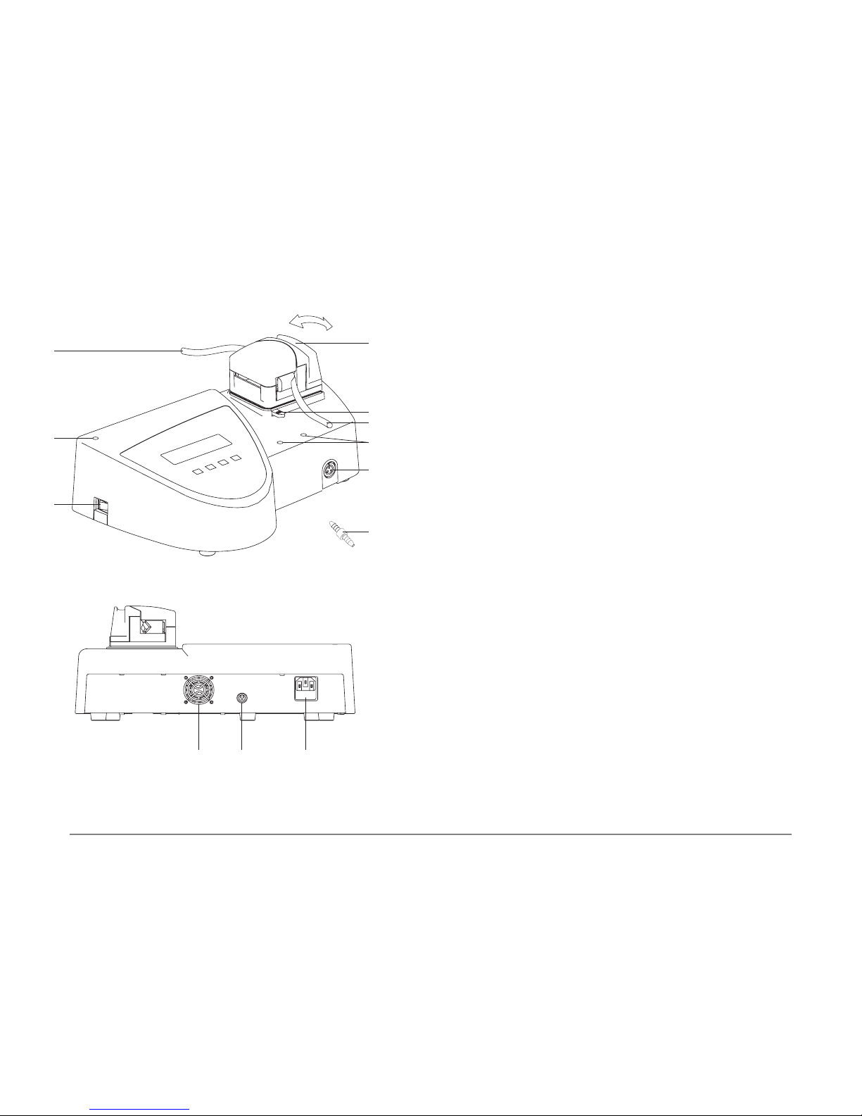
1 Insert the silicone tube into the peristaltic pump, proceeding as follows:
- Open the door (Fig.4 - Ref.A) as far as it will go (Fig.4 - Ref.B).
- Position the tube in the impeller (Fig.4 - Ref.C).
- Close the door completely (Fig.4 - Ref.E).
�
DANGER: Personal injury.
The footswitch of the Piezosurgery must not be activated when the door of the peristaltic pump
is open (Fig.4 - Ref.B). Moving parts could cause personal injury of the operator
2 Insert the rod for supporting the bag into the hole provided for it (Fig.5 - Ref.E).
3 Insert the handpiece support into the two holes provided for it (Fig.5 - Ref.C).
4 Connect the footswitch to the casing of the device by inserting the plug into the footswitch
socket (Fig.5 - Ref.H).
5 Plug the power cable into the connector on the casing of the device (Fig.5 - Ref.I) and then into
the power outlet.
6 Connect the Piezosurgery cord to the cord connector on the device (Fig.5 - Ref.D).
7 Insert the tube of the Piezosurgery into the pump tting (Fig.5 - Ref.N). Insert the pump tting
into the tube of the peristaltic pump (Fig.5 - Ref.M).
8 Connect end of the tube of the peristaltic pump (Fig.5 - Ref.L) to the ow-control system.
9 Connect the ow-control system to the bag containing the appropriate liquid for the treatment.
Page 7
12
Piezosurgery // - manual of use and maintenance
13
Piezosurgery // - manual of use and maintenance
05.0 Use
05.1 Controls
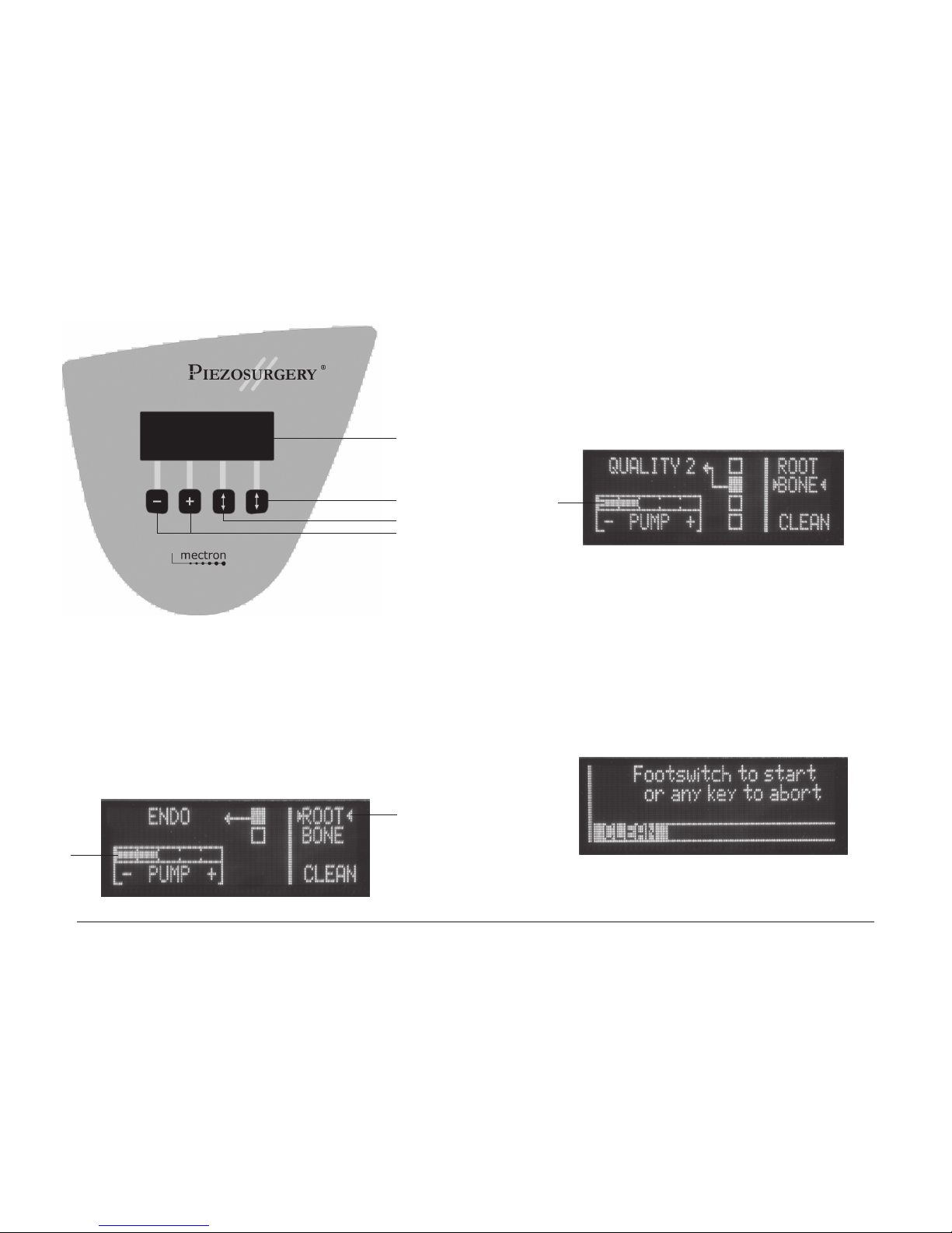
This section illustrates the parts of the front panel (Fig.6) of the Piezosurgery unit, enabling the
controls described in this manual to be located immediately.
Description of the controls
Ref. A - Graphic display.
Function The display shows the following information:
The type of power setting ROOT/BONE
The output power level set in the ROOT mode. ENDO/PERIO
The output power level set in the BONE mode. QUALITY 1/2/3 and SPECIAL
The delivery rate of the pump. PUMP: 5 Levels
The cleaning cycle for the liquid circuit. CLEAN
Ref. B - Pair of 2 keys: PUMP + and -. + -
Function These can be used to set the delivery rate of the peristaltic pump
Ref. C - Power-level key
Function This key is used to set the output power level required
Ref. D - Power-type key
Function This key is used to set the type of output power required: ROOT/BONE;
This key is used to set the CLEAN function by holding down the key for 5 seconds.
Other controls for operating the device are:
Ref. F (Fig.5) - The ON/OFF switch.
Function For supplying electricity to the device.
Ref. G (Fig.3) - The enabling footswitch.
Function For activating operation of the device.
05.2 Switching the device ON and OFF
Switching the device on
1 Power up the device by turning on the MAIN SWITCH (Fig.5 - Ref.F) situated on the casing of
the device, taking care not to press the footswitch.
2 The device will switch on.
Switching the device off
1 Power down the device by turning off the MAIN SWITCH (Fig.5 - Ref.F) situated on the casing
of the device.
2 The device will switch off.
Fig. 5
A
C
E
L
M
D
F
HG I
N
B
Page 8
14
Piezosurgery // - manual of use and maintenance
15
Piezosurgery // - manual of use and maintenance
05.3 Description of the display and functions
This point describes the three “screens” shown on the Piezosurgery display and their functions.
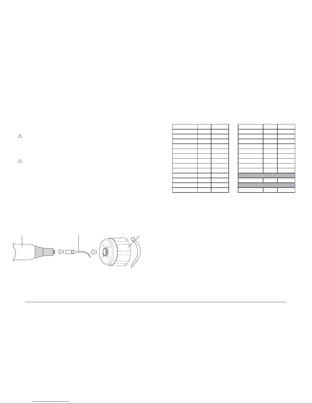
With the Piezosurgery device, two different power modes can be used. These are ROOT and
BONE. Press the arrow key (Fig.6 - Ref.D) to set the required power mode. The type of power that
has been chosen will be indicated between two pointers (Fig.7 - Ref.B).
Device in the ROOT mode Fig. 7 - In the ROOT mode, press the power-level key (Fig.6 - Ref.C)
to set the following functions:
- ENDO
- PERIO
To adjust the delivery rate of the pump, press the + and – keys (Fig.6 - Ref.B). In the ROOT mode,
the speed can be set to between nought and ve. The display will show the speed that has been
selected (Fig.7 - Ref.A).
Device in the BONE mode Fig. 8 - In the BONE mode, press the power-level key (Fig.6 - Ref.C)
to set the following functions:
- QUALITY 1
- QUALITY 2
- QUALITY 3
- SPECIAL
To adjust the delivery rate of the pump press the + and – keys (Fig.6 - Rif.B). In the BONE mode,
the speed can be set to between one and ve. The display will show the speed that has been
selected (Fig.8 - Ref.A).
A
D
C
B
Fig. 6
Fig. 7
B
A
Fig. 8
A
Fig. 9
Device in the CLEAN mode: Fig. 9 - The device has a CLEAN function, which can be used to
carry out a cleaning cycle of the hydraulic circuit. This function must be carried out after using the
device, before cleaning, disinfecting and sterilising all the parts (See Section 06.0).
To activate the CLEAN function, press the power selection key and hold it down for 5 seconds
(Fig.6 - Ref. D). The following message will appear on the display “Footswitch to start or a key to
abort”. This tells the operator to press the footswitch to start the cleaning cycle or to press any of
the four keys below the display to exit from the CLEAN function. For further indications concerning
the CLEAN function, see point 06.1.
Page 9

16
Piezosurgery // - manual of use and maintenance
17
Piezosurgery // - manual of use and maintenance
05.4 Safety requirements during use
�
DANGER: Contraindications.
Do not use the Piezosurgery on patients with pacemakers or other implantable electronic devices.
This requirement also applies to the operator.
�
DANGER: Breakage and wear of the inserts.
High frequency oscillations and wear may, on rare occasions, lead to breakage of an insert. If the
shape of an insert has been altered or if it is otherwise damaged, it is liable to break while it is
being used. Inserts in these conditions should not be used under any circumstances. In order
to avoid ingestion by the patient of a fragment of a broken insert, he/she should be instructed to
breathe through his/her nose during the treatment.
�
DANGER: Control of infections.
For maximum safety of both the patient and the operator, clean, disinfect and sterilise the piezoelectric handpiece, the inserts and the torque wrench after each treatment. Follow the appropriate
instructions for doing this provided in point 06.0 “CLEANING AND STERILISATION”.
�
WARNING: Contraindication.
Do not carry out treatments on metal or ceramic prosthetic artefacts. The ultrasonic vibrations could
cause decementing of such artefacts.
�
WARNING: Contraindication.
After autoclave sterilising of the handpiece, wait for it to cool down completely before using it.
�
WARNING: The electrical contacts inside the cord connector must be dry.
Before connecting the handpiece to the device, make sure that the electrical contacts of the
connector are perfectly dry, in particular after the autoclave sterilisation cycle. If necessary, dry the
contacts by blowing air onto them with the syringe
�
WARNING: After using aggressive solutions, it is necessary to carry out a cleaning cycle of the
tubes and handpiece with distilled water, using the clean function (See point 06.1). If the tubes are
not cleaned, crystallisation of the salts could seriously damage the device.
�
WARNING: To use the device correctly, it is necessary to press the footswitch and start it up
without letting the insert rest on the part to be treated. This will allow the electronic circuit to detect
the point where resonance of the insert is best without any interference, thus enabling optimum
performance.
If this is not done, contact with the part to be treated or with other surfaces before start-up could
cause tripping of the protection systems.
�
WARNING: For spray treatment, use only inserts through which liquid is passed.
05.5 Protection systems and alarms
The device has a diagnostics circuit that is used to recognize tripping of the protection systems and
of the alarms. These are shown on the display, as follows:
ERR0 Switch the device off and then on again. If the problem persists contact the Mectron
Service Centre
ERR1 Signal that the general protection system has been activated:
- Piezosurgery handpiece not connected to the device.
- Tuning circuit not working correctly.
- Handpiece failure.
ERR 2 Signal that the general protection system has been activated:
- Piezosurgery handpiece not connected to the device.
- Tuning circuit not working properly.
- Handpiece failure.
ERR 3 For the manufacturer only - Contact the Mectron Service Centre.
ERR 4 Signal that the general protection system has been activated:
- Tuning circuit not working properly.
- Handpiece failure.
ERR 5 Signal that the tuning scan has failed:
- Insert not correctly secured to the handpiece.
- Insert worn, broken or deformed.
- Electrical contacts of cord wet
ERR 6 Signal that the “power supply out of range” protection system has been tripped.
ERR 8 Signal indicating an error in communications with the scaler module.
ERR 9 Signal indicating an error in pump operation:
- Check whether the pump and tube are correctly installed.
- Check whether the pump is prevented from turning
ERR CKS Error signal. Firmware. Firmware checksum incorrect:
- If the equipment is working properly, call as soon as possible.
- If the equipment is not working correctly, stop using it and call the Mectron Service
Centre immediately.
Page 10
18
Piezosurgery // - manual of use and maintenance
19
Piezosurgery // - manual of use and maintenance
05.6 Instructions for use
1 Open the air intake on the drip system.
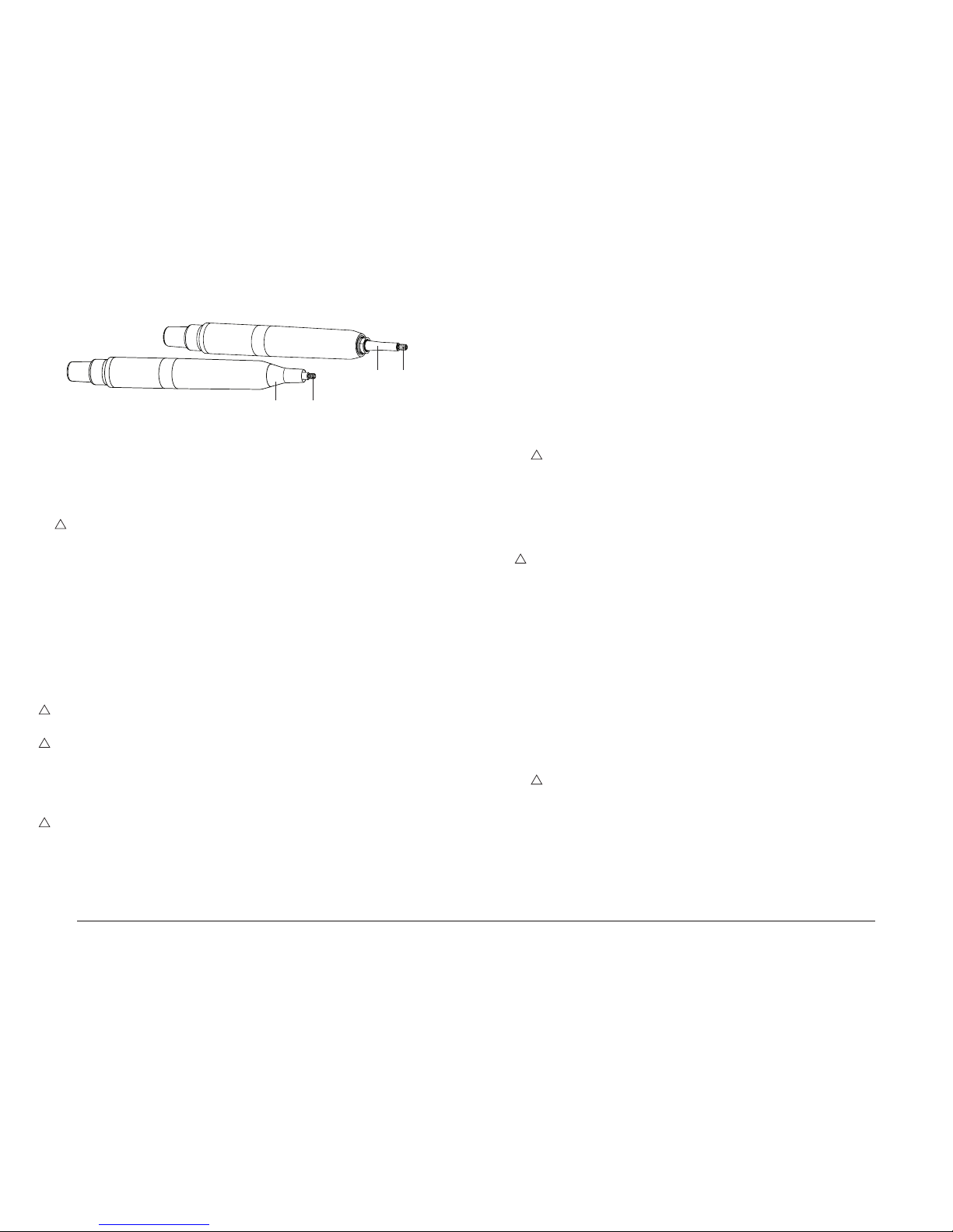
2 Screw the chosen insert onto the Piezosurgery handpiece until it is ush against it
(Fig.10 - Ref.A).
3 Use the wrench included the supply to tighten the insert.
To use the torque wrench correctly (Fig.10 - Rif.B) proceed as follows:
- Hold the body of the handpiece rmly;
�
WARNING: Do not grip the end part of the handpiece or the cord, only the plastic casing
(Fig.10 - Ref.C), and do not turn it while fastening the insert in place;
- Turn the wrench in a clockwise direction until the clutch engages (the outer body of the key
turns in relation to the casing of the handpiece, making clicking sounds):
- The insert is now properly tightened in place.
4 Make sure that the Piezosurgery handpiece is correctly connected to the device connector
(Fig.5 - Ref.D).
5
�
WARNING: To set the Mode and Power parameters correctly on the basis of the type of
insert to be used, consult Table 1 or the leaet accompanying the Mectron insert you have
purchased.
6 Check the display to see the power mode that has been set (See point 05.3). Use the power
mode selection key (Fig. 6 - Ref.D) to choose between the ROOT and BONE modes.
7 Check the display to see the level of power that has been set (See point 05.3), then use the
power level selection key (Fig. 6 - Ref.C) to make your choice depending on the power mode:
- ROOT ENDO - PERIO
- BONE QUALITY 1 - QUALITY 2 - QUALITY 3 - SPECIAL
8 Check the display to see the delivery rate of the peristaltic pump (see point 05.3). If the delivery
rate required is other than the level that has been set, use the PUMP + and – keys (Fig.6 -
Ref.B) to choose between the following, depending on the type of power that has been set:
- ROOT 6 delivery rate levels From 0 to 5
- BONE 5 delivery rate levels From 1 to 5
NOTE: Sprayless treatment is only possible in the ROOT function, setting the delivery rate
of the peristaltic pump PUMP to nought (Fig.7 - Ref.A). No notches should be shown on the
display.
05.7 Permissible settings on the basis of the type of insert
Table 1 shows the Mode and Power level settings permissible for correct use of the instrument.
Table 1:
Insert Mode Power level Insert Mode Power level
EL1 - EL2 - EL3 ROOT ENDO** OT1 - OT1A BONE 1* ÷ 2* ÷ 3*
EN1 - EN2 ROOT ENDO** OT2 - OT3 - OT4 BONE 1* ÷ 2* ÷ 3*
EN3 - EN4 ROOT ENDO** OT5 - OT5A - OT5B BONE 1* ÷ 2* ÷ 3*
EX1 - EX2 - EX3 BONE 1* ÷ 2* ÷ 3* OT6 BONE 1* ÷ 2* ÷ 3*
IM2A BONE 1* ÷ 2* ÷ 3* OT7 - OT7A BONE 1* ÷ 2* ÷ 3*
IM2P BONE 1* ÷ 2* ÷ 3* OT7S-3 - OT7S-4 BONE SPECIAL**
IM3A BONE 1* ÷ 2* ÷ 3* OT8L - OT8R BONE 1* ÷ 2* ÷ 3*
IM3P BONE 1* ÷ 2* ÷ 3* PP1 ROOT PERIO
OP1 - OP2 BONE 1* ÷ 2* ÷ 3* PS1 - PS2 - PS6 ROOT PERIO
OP3 - OP3A BONE 1* ÷ 2* ÷ 3* Periodontal Surgery
OP4 BONE 1* ÷ 2* ÷ 3* OP5 ROOT PERIO
OP6 - OP6A ROOT PERIO Implant Surgery
OP7 BONE 1* ÷ 2* ÷ 3* OP5 BONE 1* ÷ 2* ÷ 3*
* *Quality 1 = Maximum power - Quality 2 = Medium power - Quality 3 = Minimum power
** Maximum permissible power
05.8 Rules for keeping the device in proper working order
1 Check the state of wear of the inserts periodically and replace any for which a drop in perform-
ance is noted.
2 Do not alter the shape of the inserts by bending or ling them.
3 Replace any insert that has become deformed or damaged by impacts.
4 Always make sure that any threaded parts and their contact surfaces are perfectly clean.
5 If an insert becomes too worn, the device will stop working.
A BC
Fig. 10
Page 11

20
Piezosurgery // - manual of use and maintenance
21
Piezosurgery // - manual of use and maintenance
06.0 Cleaning and sterilisation
06.1 CLEAN function - Cleaning of the liquid circuit
�
WARNING: Failure to carry out cleaning of the tubes will lead to crystallisation of salts that can
seriously damage the equipment.
�
WARNING: The cord cannot be detached from the handpiece.
The device has a CLEAN function (See point 05.3) that can be used to run a cleaning cycle to
clean the hydraulic circuit. This function must be carried out after using the device, before cleaning
and sterilising all the parts (see following points)..
1 Prepare a solution of enzymatic detergent with a pH of 6 to 9, in accordance with the manufac-
turer’s instructions.
2 Disconnect the tube of the peristaltic pump from the ow-control system.
3 Place the tube in a receptacle containing the enzymatic detergent.
4 To activate the CLEAN function, press the power level selection key and hold it down for 5
seconds (Fig. 6 - Ref.D). The following message will appear on the display: “Footswitch to start
or a key to abort”.
5 Fit one of the inserts used during the operation onto the handpiece.
6 Place the handpiece over a bowl to collect the water that pours out of it during the cleaning
cycle.
7 Press the footswitch briey to start the cleaning cycle. As soon as the peristaltic pump starts up
a status bar will appear on the display to indicate progressively the time remaining to comple-
tion of the CLEAN cycle. The cycle lasts for 20 seconds and once it has started it cannot be
stopped.
8 Upon completion of the cleaning cycle, the device exits from the CLEAN function and returns to
whatever function had been set previously.
9 Repeat the operations described above from point 4 onwards to carry out a cleaning cycle for
each of the tubes and for all of the accessories used, i.e.:
- Handpieces;
- Peristaltic pump tubes;
- Fittings.
10 Carry out a CLEAN cycle using distilled water to remove any residual detergent.
11 After completion of the cleaning operations, empty the tubes and dry the accessories and dry
the accessories that have been subjected to the cleaning cycle.
06.2 Cleaning and disinfecting the casing of the device
�
DANGER: Switch off the device.
Always turn off the device by means of the switch (Fig. 5 - Ref. F) and disconnect it from the power
outlet before carrying out the following cleaning and disinfection activities.
�
DANGER: The casing of the device is not protected against the penetration of liquids. Do
not spray liquids directly onto the surface of the casing of the device.
�
DANGER: The device cannot be sterilised.
After each treatment carry out the following operations:
1 Remove the insert from the handpiece.
2 Clean and disinfect the surfaces of the casing, the cords and their connectors using a low-
linting cloth moistened with a mild detergent solution (pH 6 to 9) and/or non-aggressive
disinfectant having a neutral pH (pH 7). Follow the instructions supplied by the manufacturer
of the disinfectant solution carefully. Allow the disinfectant solution to dry in air before using the
device.
NOTE: Water-based disinfectant solutions with a neutral pH are highly recommended. Alcoholbased disinfectants are not recommended as they could discolour and/or otherwise damage plastic
materials.
06.3 Sterilisation procedure
�
WARNING: Carry out sterilisation using only a steam autoclave.
Do not use any other type of sterilising procedure (dry heat, radiation, ethylene oxide, gas,
low-temperature plasma, etc.).
�
DANGER: Infection control - Parts that can be sterilised - Thoroughly remove all
residues before sterilising.
In order to avoid bacterial or viral infections, always clean, disinfect and sterilise the following components after each treatment:
1 Handpiece (Fig. 3 - Ref.E);
2 Inserts (Fig. 3 - Ref.C);
3 Wrench for tightening the inserts (Fig. 3 - Ref.D);
4 Tube for peristaltic pump (Fig. 3 - Ref.I);
5 Fitting between the cord and the tube of the peristaltic pump (Fig. 3 - Ref.F).
These components are made of materials able to withstand a maximum temperature of 135°C for
20 minutes at most.
The steam autoclave sterilising process must be carried out using one of the following two parameters:
- Cycle at 121°C for 16 minutes.
- Cycle at 134°C for 4 minutes.
All the stages of sterilisation must be carried out by the operator in accordance with
EN ISO 17665-1:2006, EN ISO 556-1:2001 and ANSI/AAMI ST:46:2002 standards.
NOTE: Do not use hydrogen peroxide for disinfecting. Use only disinfectants with a neutral pH.
Always rinse with sterile water.
06.4 Cleaning and autoclave sterilisation of the handpiece
�
WARNING: The cord cannot be detached from the handpiece.
�
WARNING: Disconnect the handpiece from the device only by unplugging the connector.
�
WARNING: Do not dip the handpiece into disinfectant solutions or liquids of any other
kind since this could damage it.
�
WARNING: Do not place the handpiece in an ultrasonic tank.
�
WARNING: Do not sterilise the handpiece with an insert screwed onto it.
Page 12
22
Piezosurgery // - manual of use and maintenance
23
Piezosurgery // - manual of use and maintenance
NOTE: Do not use hydrogen peroxide for disinfecting. Use only disinfectants with a neutral pH and
always rinse with sterile water.
Clean the handpiece thoroughly, taking special care to clean the threaded pin onto which the
inserts are screwed (Fig.11 - Ref.B) and to the adjacent ring-shaped cavity.
1 Prepare a solution of enzymatic detergent* with a pH of between 6 and 9, following the manu-
facturer’s instructions.
�
WARNING: Carry out the CLEAN function on the handpiece (Point 06.1).
2 Unscrew the insert.
3 Unscrew the metal front cone (Fig.11 - Ref.A).
4 Clean the surfaces of the casing, the cords and the connectors using a low-linting coloth mois-
tened with a detergent solution (pH between 6 and 9) and disinfect them with a mild disinfect-
ant having a neutral pH (pH7).
5 Brush the surface of the handpiece gently with a soft nylon brush, paying special attention to
the following parts:
- Thread of the handpiece (Fig.11 - Ref.B);
- Titanium stem (Fig.11 - Ref.C);
- Front cone (Fig.11 - Ref.A), externally and internally.
6 Rinse thoroughly with distilled water to eliminate any residual detergent.
7 Re-assemble the front cone onto the handpiece (Fig. 11 - Ref. A).
8 Dry the electric contacts by blowing air onto them with the syringe.
9 Seal the handpiece in an individual disposable bag (without any inserts).
10 Sterilise the handpiece in a steam autoclave.
�
WARNING: Allow the handpiece to cool down completely after the sterilisation cycle
before using it.
�
WARNING: The electric contacts of the connector must be dry.
At the end of the sterilisation cycle, make sure that the electric contacts of the connector are
perfectly dry before connecting the cord to the device. If necessary, dry the contacts by blowing air
onto them with the syringe.
06.5 Cleaning and autoclave sterilisation of the inserts
�
WARNING: Do not use hydrogen peroxide.
Do not use hydrogen peroxide to sterilise the inserts. Use only disinfectants with a neutral pH, and
always rinse with sterile water.
1 Prepare a solution of enzymatic detergent* with a pH of between 6 and 9, following the manu-
facturer’s instructions.
2 Soak the insert in the enzymatic detergent solution for 10 minutes at 40°C.
3 Brush the surface of the insert gently with a soft nylon brush.
4 Use a syringe to inject the enzymatic detergent into the cavity of the insert. Repeat this opera-
tion three times in order to remove all the residues from the inner surface effectively.
5 Rinse with distilled water injected at a pressure of (3.8 bars) for at least 10 seconds so as to
remove any residues.
6 Place the insert in an ultrasonic tank with the enzymatic solution at 40°C, leaving it for at least
10 minutes.
7 Rinse the insert with distilled water.
8 Brush the surface of the insert again gently with a soft nylon brush.
9 Rinse with distilled water injected at a pressure of 3.8 bars for at least 10 seconds so as to
eliminate any residues.
�
WARNING: Make sure that the insert is absolutely dry also internally before starting the
sterilising cycle. To do this, blow air into it through the hole with the syringe. This will prevent
the appearance of stains or patches on the surface of internal oxidising of the insert.
10 Seal the inserts individually in disposable bags.
11 Sterilse the inserts in a steam autoclave.
06.6 Cleaning and autoclave sterilisation of the wrench for tightening the
inserts
�
WARNING: Do not use hydrogen peroxide.
Do not use hydrogen peroxide to disinfect the wrench for tightening the inserts. Use only
disinfectants with a neutral pH. Always rinse with sterile water.
1 Prepare a solution of enzymatic detergent* with a pH of between 6 and 9, following the
manufacturer’s instructions.
2 Soak the wrench in the enxymatic detergent for 10 minutes at 40°C.
3 Brush both the internal and the external surfaces of the wrench gently with a soft nylon brush.
4 Rinse the wrench with distilled water until it can be seen that the contaminated parts have been
removed.
5 Place the wrench in an ultrasonic tank with the enzymatic detergent solution at 40°C, leaving it
there for at least 10 minutes.
6 Rinse with distilled water to eliminate any residues.
7 Seal the wrench in an individual disposable bag.
8 Sterilise the wrench in a steam autoclave.
06.7 Autoclave sterilising of the tube of the peristaltic pump
1 Prepare a solution of enzymatic detergent with a pH of between 6 and 9, following the
manufacturer’s instructions.
�
WARNING: Carry out the CLEAN function on the tube of the peristaltic pump (Point 06.1).
2 Clean the tube of the peristaltic pump with the enzymatic solution.
3 Rinse with distilled water and dry thoroughly.
Note: Do not use hydrogen peroxide to disinfect the tube. Use only disinfectants with a neutral
pH. Always rinse with sterile water and dry thoroughly.
4 Seal the tube individually in a a disposable bag.
5 Sterilise the tube in a steam autoclave.
* Process validated by an independent organisation using the enzymatic detergent Cidezime® (Enzol®).
Fig. 11
A B
C B
Page 13

24
Piezosurgery // - manual of use and maintenance
25
Piezosurgery // - manual of use and maintenance
08.0 Replacement of the fuses
�
DANGER : Switch off the apparatus.
Always turn off the apparatus by means of the switch (Fig.5 - Ref.F) and disconnect it from the
power outlet before carrying out the following maintenance activities.
1 Insert the at tip of a screwdriver into the recess in the fuse compartment below the power
socket and use it as a lever (Fig.12 - Ref.A).
2 Pull out the fuse compartment (Fig.12 - Ref.B).
3
�
DANGER: Replace the fuses, using fuses of the type indicated on the identication label on
the bottom of the apparatus. Depending on the mains power supply, these fuses may be rated
as follows:
230 VAC 500 mA T
115 VAC 1 mA T
100 VAC 1,2 mA T
4 Put the compartment back into place (Fig.12 - Ref.B).
Fig. 12
A B
09.0 Disposal procedures and precautions
- This equipment must be disposed of and treated as waste requiring separate collection;
- At the end of the life-cycle of this equipment, the purchaser is entitled to return the equipment
to the dealer supplying new equipment. Instructions for disposal are available from Mectron;
- Failure to comply with the foregoing points may entail punishment in accordance with Directive
2002/96/EC.
�
DANGER: Hospital waste.
Treat the following items as hospital waste:
- Inserts, when worn or broken;
- Irrigator, after each treatment;
- Tube of the peristaltic pump, after 8 sterilising cycles;
- Torque wrench for tightening inserts, when worn or broken.
06.8 Autoclave sterilising of the tting between the cord and the tube of
the peristaltic pump
1 Prepare a solution of enzymatic detergent with a pH of between 6 and 9, following the
manufacturer’s instructions.
�
WARNING: Carry out the CLEAN function on the tting of the peristaltic pump tube (Point
06.1).
2 Clean the tting of the peristaltic pump tube with the enzymatic solution prepared as above.
3 Rinse with distilled water to eliminate any residues of detergent and dry thoroughly.
NOTE: Do not use hydrogen peroxide to disinfect the tting. Use only disinfectants with a
neutral pH. Always rinse with sterile water.
4 Seal the tting individually in a a disposable bag.
5 Sterilise the tting in a steam autoclave.
07.0 Regular maintenance
07.1 Shelf Storage
If the device is not used for several days running, follow the recommendations indicated below:
1 Carry out the cleaning cycles for the water circuits using the CLEAN function (see point “06.1”).
2 Disconnect the device from the power mains.
3 Carry out cleaning, disinfection and sterilisation (see Section “06.0”)
07.2 Power-supply cable
�
DANGER: Check regularly that the power cable is intact. If it is damaged, replace it with an
original Mectron spare.
Page 14
26
Piezosurgery // - manual of use and maintenance
27
Piezosurgery // - manual of use and maintenance
10.0 The inserts
Sharp inserts.
The sharp edges of these inserts can be used to treat bone structures efciently and effectively.
Sharp inserts are used in osteotomy and osteoplasty when a ne and well-dened cut in the bone
structure concerned is required. There are also inserts with sharp edges for osteoplasty techniques
and for removing bone fragments.
Smoothing inserts.
The smoothing inserts have surfaces shaped in such a way that they can be used to work the bone
structures with precision and in a controlled manner. Smoothing inserts are used in osteotomy
when it is necessary to prepare difcult and delicate structures such as those for preparing a maxillary sinus window or to complete preparation of the site of an implant.
Blunt inserts.
Blunt inserts are used for separating the soft tissues, for example for detaching Schneider’s
membrane or for lateralising nerves. In periodontology, these inserts are used to smooth the root
surfaces.
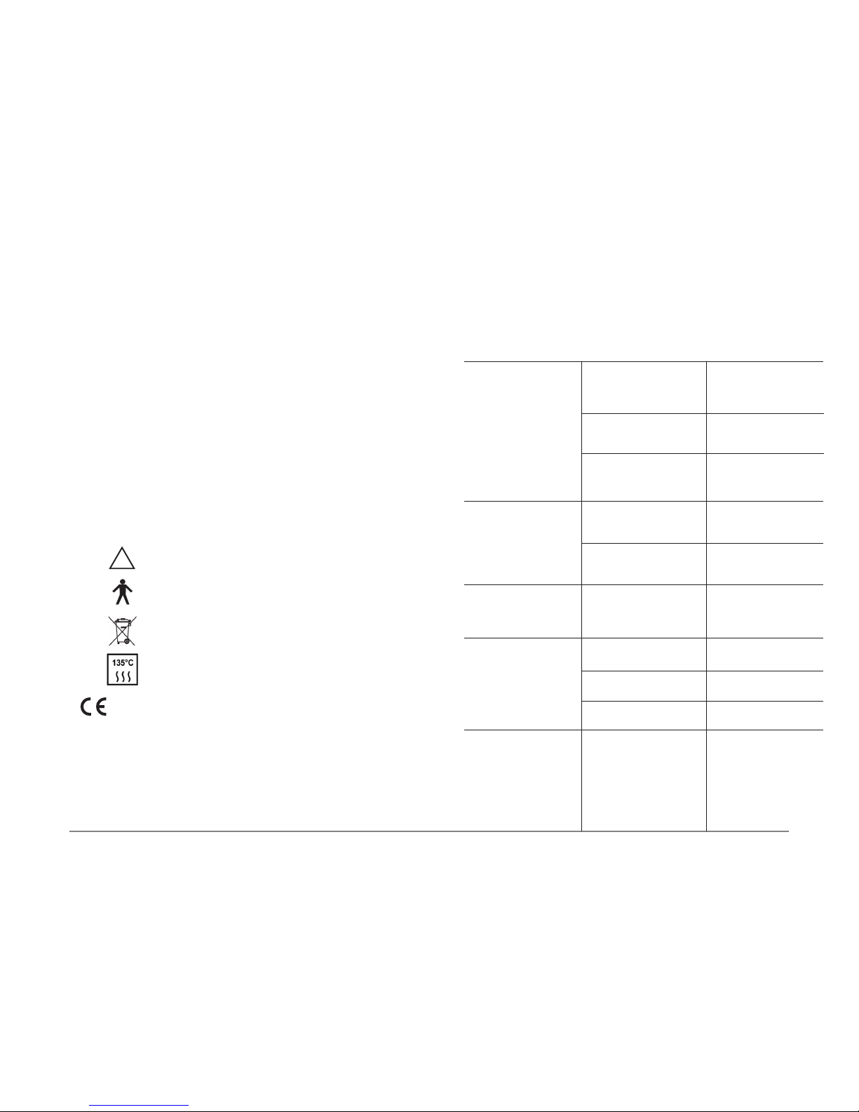
11.0 Symbols
12.0 Troubleshooting
If the device does not seem to be working properly, read the instructions again and then check the
following table.
PROBLEM POSSIBLE CAUSE SOLUTION
The device does not turn on
when the switch is positioned
on ON.
The connector on the end
of the power cable is not
plugged into the socket on the
rear of the device properly.
The power cable is faulty.
The fuses are unserviceable.
Check that the power cable is
rmly connected.
Check that the power outlet is
working properly.
Replace the power cable.
Replace the fuses (see point
“Replacement of fuses”).
The device is switched on but
will not work. No errors are
shown on the display.
The connector of the
footswitch is not properly
plugged into the socket.
The footswitch will not work.
Insert the footswitch
connector properly.
Contact the nearest
authorised MECTRON
Service Centre.
A faint whistle can be heard
coming from the Piezosurgery
handpiece during operation.
The insert is not correctly
tightened onto the scaler
handpiece.
Unscrew the insert and screw
it back into place correctly.
The device is switched on but
does not work. The message
ERR appears on the display.
The insert is not tted correctly into the handpiece.
The insert is worn, broken or
deformed.
The connector of the cord is
wet.
Unscrew the insert and screw
it back into place correctly.
Replace the insert.
Dry the connectors.
N.B.: Please read carefully the instructions for use.
�
Type “B” applied part.
This device and its accessories shouldn’t be
disposed or treated as solid urban waste.
Apparatus in accordance with EC Directive 93/42 EEC
Including EN 60601-1 and EN 60601-1-2.
Notied body: CERMET
The sterilisable materials must be autoclave sterilised
and can withstand a maximum temperature of 135° C.
Page 15

28
Piezosurgery // - manual of use and maintenance
29
Piezosurgery // - manual of use and maintenance
PROBLEM POSSIBLE CAUSE SOLUTION
The device is switched on but
will not work. The message
ERR appears on the display.
Cord not connected to the
device
Lack of continuity of a lead in
the cord.
Handpiece failure.
Malfunctioning of the tuning
circuit.
Connect the cord to the
device
Contact the nearest
authorised MECTRON
Service Centre.
Contact the nearest
authorised MECTRON
Service Centre.
Contact the nearest
authorised MECTRON
Service Centre.
No liquid comes out of the
insert during operation.
The insert is of the type with
no through-ow of liquid.
The PUMP function is set to
nought.
The bag of liquid is empty.
The drip system air intake has
not been opened.
The tubes of the drip system
and of the pump have not
been correctly installed.
The insert is clogged.
The handpiece is clogged.
Use an insert of the type with
through-ow of liquid.
Press the + key on the front
panel of the device for the
PUMP function.
Replace the bag with a full
one.
Open the air intake of the drip
system.
Check the connections of the
tubes.
Free the passage in the insert
through which the water
passes.
Contact the nearest
authorised MECTRON
Service Centre.
The device is working properly, but the pump is being
forced.
Too much pressure by the
impeller on the tube in the
peristaltic pump.
Check that the tube in the
peristaltic pump has been
correctly inserted (See page
10, point 04.3)
The pump is turning correctly
but when it stops liquid comes
out of the handpiece.
The door of the peristaltic
pump is not closed properly.
Make sure that the door of the
peristaltic pump is properly
closed (see page 10, point
04.3).
PROBLEM POSSIBLE CAUSE SOLUTION
Insufcient power. The insert is not correctly
tted to the handpiece (the
message ERR appears on the
display).
The insert is worn, broken or
deformed (the message ERR
appears on the display).
Insufcient maintenance of
the insert.
Unscrew the insert and screw
it back into place correctly.
Replace the insert.
See point “Rules for Keeping
the Device in Proper Working
Order”.
Page 16

30
Piezosurgery // - manual of use and maintenance
31
Piezosurgery // - manual of use and maintenance
13.0 Technical data
Device in accordance with Directive 93/42/EEC: Class II a.
Class according to EN 60601-1: I
Type B
IP 20 (device)
IP X8 (footswitch)
Device for intermittent operation: 60” ON 30” OFF.
Power-supply voltage: 230 VAC ± 10 % 50/60 Hz.
115 VAC ± 10 % 50/60 Hz (optional).
100 VAC ± 10 % 50/60 Hz (optional).
Max. power absorbed: 70 VA.
Fuses: Type 5 X 20 mm 230 VAC 2 X 500 mA T.
Type 5 X 20 mm 115 VAC 2 X 1 A T.
Type 5 X 20 mm 100 VAC 2 X 1,2 A T.
Working frequency: Automatic scan.
From 24 to 29.5 KHz.
Average power applied to the handpiece: Adjustable to 6 power levels:
ROOT mode Power: ENDO: 2,8 W
Power: PERIO: 4,6 W
BONE mode Power: QUALITY1: 16 W
Power: QUALITY2: 16 W
Power: QUALITY3: 16 W
Power: SPECIAL: 4,6 W
Delivery rate of the peristaltic pump: Adjustable via the keypad.
In the ROOT power mode: 6 delivery rates:
From 0 to approx. 100 ml / min.
In the BONE power mode: 5 delivery rates:
From 15 to approx. 100 ml / min circa.
Protection systems and tripping time of the APC:
- No handpiece connected
Tripping time 20 ms.
- Cord interrupted
Maximum tripping time 80 ms.
- Insert broken or not correctly tightened
Three scans, 150 ms each.
- Protection by discharge to earth
Tripping time 20 ms.
Alarms: The display on the front panel indicates error (see
point “Problem-solving”).
Operating conditions: From +10°C to +40°C.
Relative humidity from 30% to 75%.
Transport and storage conditions: From -10°C to +70°C.
Relative humidity from 10% to 90%.
Air pressure P: 500hPa/1060hPa
Cord: It is recommended not to exceed 100 sterilisation
cycles
Tube of peristaltic pump: It is recommended not to exceed 8 sterilisation
cycles
Weight and size: 3.5 Kg
L - W - H 340 X 210 X 150 mm.
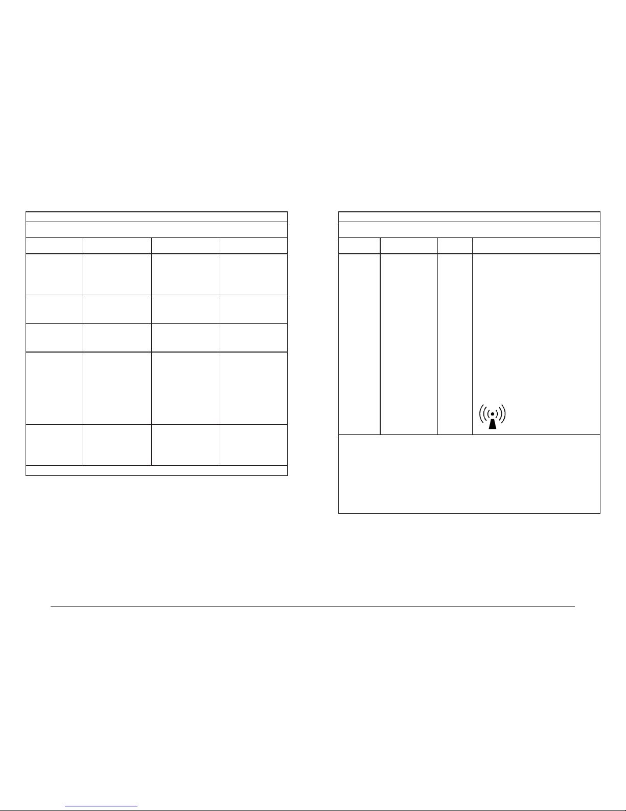
13.1 Electromagnetic compatibility EN 60601-1-2
Guidance and manufacturer’s declaration - Electromagnetic emissions
The PIEZOSURGERY // is intended for use in the electromagnetic environment specied below.
The customer or the user of the PIEZOSURGERY // should assure that it is used in such an environment.
Emissions test Compliance Electromagnetic environment - Guidance
RF emissions
CISPR 11
Group 1 The PIEZOSURGERY // uses RF energy only for its internal
function. Therefore, its RF emissions are very low and are not
likely to cause any interference in nearby electronic equipment.
RF emissions
CISPR 11
Class B The PIEZOSURGERY // is suitable for use in all establishments,
including domestic establishments and those directly connected
to the public low-voltage power supply network that supplies
buildings used for domestic purposes.
Harmonic emissions
IEC 61000-3-2
Class A
Voltage uctuations / icker
emissions
IEC 61000-3-3
Complies
Page 17
32
Piezosurgery // - manual of use and maintenance
33
Piezosurgery // - manual of use and maintenance
Guidance and manufacturer’s declaration - Electromagnetic immunity
The PIEZOSURGERY // is intended for use in the electromagnetic environment specied below.
The customer or the user of the PIEZOSURGERY // should assure that it is used in such an environment.
Immunity test IEC 60601
test level
Compliance level Electromagnetic envi-
ronment - Guidance
Electrostatic
discharge (ESD)
IEC 61000-4-2
±6 kV contact
±8 kV air
±6 kV contact
±8 kV air
Floors should be wood,
concrete or ceramic tile. If
oors are covered with
synthetic material, the
relative humidity should
be at least 30 %.
Electrical fast
transient/burst
IEC 61000-4-4
±2 kV for power supply
lines
±1 kV for input/output lines
±2 kV for power supply
lines
±1 kV for input/output lines
Mains power quality
should be that of a typical
commercial or hospital
environment.
Surge
IEC 61000-4-5
±1 kV differential mode
±2 kV common mode
±1 kV differential mode
±2 kV common mode
Mains power quality
should be that of a typical
commercial or hospital
environment.
Voltage dips, short
interruptions and
voltage variations on
power supply input
lines
IEC 61000-4-11
<5 % U
T
(>95 % dip in UT)
for 0,5 cycle
40 % UT (60 % dip in UT)
for 5 cycle
70 % UT (30 % dip in UT)
for 25 cycle
<5 % UT (>95 % dip in UT)
for 5 s
<5 % UT (>95 % dip in UT)
for 0,5 cycle
40 % UT (60 % dip in UT)
for 5 cycle
70 % UT (30 % dip in UT)
for 25 cycle
<5 % UT (>95 % dip in UT)
for 5 s
Mains power quality
should be that of a typical
commercial or hospital
environment.
Power frequency
(50/60 Hz) magnetic
eld
IEC 61000-4-8
3 A/m 3 A/m Power frequency
magnetic elds should be
at levels characteristic of
a typical location in a
typical commercial or
hospital environment.
NOTE: U
T
is the a.c. mains voltage prior to application of the test level.
Guidance and manufacturer’s declaration - Electromagnetic immunity
The PIEZOSURGERY // is intended for use in the electromagnetic environment specied below.
The customer or the user of the PIEZOSURGERY // should assure that it is used in such an environment.
Immunity test IEC 60601 test level
Complian-
ce level
Electromagnetic environment - Guidance
Conducted RF
IEC 61000-4-6
Radiated RF
IEC 61000-4-3
3 Veff
150 kHz to 80 MHz
3 V/m
80 MHz to 2,5 GHz
3 Vrms
3 V/m
Portable and mobile RF communications equipment
should be used no closer to any part of the disposal
including cables, than the recommended separation
distance calculated from the equation applicable to
the frequency of the transmitter.
Recommended separation distance
d = 1,2 √P
d = 1,2 √P 80 MHz to 800 MHz
d = 2,3 √P 800 MHz to 2,5 GHz
where P is the maximum output power rating of the
transmitter in watts (W) according to the transmitter
manufacturer and d is the recommended separation
distance in metres (m).
Field strengths from xed RF transmitters, as deter-
mined by an electromagnetic site
a
survey,a should
be less than the compliance level in each frequency
rangeb.
Interference may occur in the vicinity of equipment
marked with the following symbol:
Notes:
(1) At 80 MHz and 800 MHz, the higher frequency range applies.
(2) These guidelines may not apply in all situations. Electromagnetic propagation is affected by absorption
and reection from structures, objects and people.
a Field strengths from xed transmitters, such as base stations for radio (cellular/cordless) telephones and
land mobile radios, amateur radio, AM and FM radio broadcast and TV broadcast cannot be predicted
theoretically with accuracy. To assess the electromagnetic environment due to xed RF transmitters, an
electromagnetic site survey should be considered. If the measured eld strength in the location in which
the PIEZOSURGERY // is used exceeds the applicable RF compliance level above, the
PIEZOSURGERY // should be observed to verify normal operation. If abnormal performance is observed,
additional measures may be necessary, such as re-orienting or relocating the PIEZOSURGERY //.
b Over the frequency range 150 kHz to 80 MHz, eld strengths should be less than 3 V/m.
Page 18

34
Piezosurgery // - manual of use and maintenance
35
Piezosurgery // - manual of use and maintenance
Recommended separation distances between portable and mobile RF communications equipment
and the PIEZOSURGERY //
The PIEZOSURGERY // is intended for use in an electromagnetic environment in which radiated RF
disturbances are controlled. The customer or the user of the PIEZOSURGERY // can help prevent electromagnetic interference by maintaining a minimum distance between portable and mobile RF communications
equipment (transmitters) and the PIEZOSURGERY // as recommended below, according to the maximum
output power of the communications equipment.
Rated maximum
output power of
transmitter “W”
Separation distance according to frequency of transmitter “m”
150 kHz to 80 MHz
d = 1,2 √P
80 MHz to 800 MHz
d = 1,2 √P
800 MHz to 2,5 GHz
d = 2,3 √P
0,01 0,12 0,12 0,23
0,1 0,38 0,38 0,73
1 1,2 1,2 2,3
10 3,8 3,8 7,3
100 12 12 23
For transmitters rated at a maximum output power not listed above, the recommended separation distance d
in metres (m) can be estimated using the equation applicable to the frequency of the transmitter, where P is
the maximum output power rating of the transmitter in watts (W) according to the transmitter manufacturer.
Note:
(1) At 80 MHz and 800 MHz, the separation distance for the higher frequency range applies.
(2) These guidelines may not apply in all situations. Electromagnetic propagation is affected by absorption and
reection from structures, objects and people.
14.0 Guarantee
Before being placed on the market, all MECTRON equipment undergoes a thorough nal check to
ensure that it is are in proper working order.
MECTRON guarantees its products, purchased new from a MECTRON dealer or importer, to be
free from manufacturing or material defects for:
- 2 (TWO) YEARS from the date of purchase for the device;
- 1 (ONE) YEAR from the date of purchase for the handpiece with its cord.
Throughout the warranty period, MECTRON undertake to repair (or, at their sole discretion, to
replace) free of charge any parts that, in their opinion, are faulty.
Complete replacement of MECTRON products is excluded.
Mectron cannot accept any liability for direct or incidental damage or personal injury in the following
cases:
- If the equipment is used for purposes other than that for which it is intended.
- If the equipment is not used in accordance with all the instructions and requirements described
in this manual.
- If the wiring system in the room where the equipment is used does not comply with the
applicable standards and appropriate requirements.
- If the wiring system in the room where the equipment is used does not comply with the
applicable standards and appropriate requirements.
- If any assembly operations, extensions, settings, alterations or repairs have been carried out
by personnel not authorised by Mectron.
- If the environmental conditions in which the device is kept and stored do not comply with the
requirements indicated in the chapter on technical specications.
Accidental damages due to transport, incorrect use or carelessness or to connection to power
supplies other than as envisaged and damage to the signalling lamps, handpieces and all
accessories are excluded from the warranty.
The warranty will no longer apply if the apparatus has been tampered with or repaired by
unauthorised personnel.
WARNING
The warranty is valid only if the warranty slip enclosed with the product has been completed in full
and returned to us or, if appropriate, to your MECTRON dealer or importer within 20 (TWENTY)
DAYS from the date of purchase, as proven by the consignment note/invoice issued by the
dealer/importer.
In order to benet from the warranty service, the customer must return the apparatus to be repaired
to the MECTRON dealer/importer from which it was purchased, at his own expense.
The apparatus should be returned suitably packed (possibly in its original packing material),
accompanied by all the accessories and by the following information:
a) Owner’s details, including his telephone number.
b) Details of the dealer/importer
c) Photocopy of the consignment note/purchase invoice of the apparatus issued to the owner and
indicating, in addition to the date, also the name of the apparatus and its serial number.
d) A description of the problem.
Transport and any damages caused during transport are not covered by the warranty.
In the event of failures due to accidents or improper use, or if the warranty has lapsed, repairs to
MECTRON products will be charged on the basis of the actual cost of the materials and labour
required for such repairs.
Page 19

Mectron S.p.A.
Via Loreto 15/A
16042 Carasco (Ge) Italy
Tel. +39 0185 35361
Fax +39 0185 351374
www.mectron.com
e-mail: [email protected]
Rivenditore - Reseller - Wiederverkäufer - Revendeur - Revendedor
Piezosurgery // V. GB
Rev. 09 Del 07-11-2008
 Loading...