

Page 1
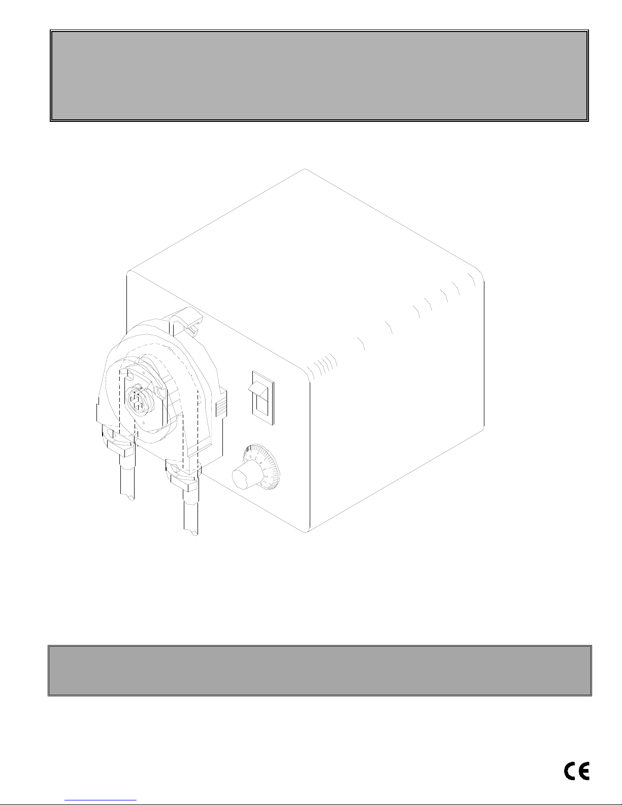
DOLPHIN SERIES
sales@novatech-usa.com
www.novatech-usa.com
Tel: (866) 433-6682 Fax: (866) 433-6684
Tel: (281) 359-8538 Fax: (281) 359-0084
Installation, Operation and
Maintenance Manual
LIQUID CHEMICAL SOLUTION and
SLURRY METERING PUMPS
Dolphin-10, Dolphin-50 and Dolphin-75 Models
READ ALL WARNINGS CAREFULLY BEFORE
INSTALLING PUMP
Page 2
PUMP DATA/SPECIFICATIONS
Fill in information from pump data label
Series: ______________________
Serial #: ______________________
Model #: ______________________
Nominal output: ______________________
Maximum pressure: ______________________
Volts/Hz/Amps/Phase: ______________________
KOPkit
®
#: ______________________
Tubing material/size: ______________________
WARRANTY:
The manufacturer warrants its equipment of its manufacture to be free of defects in material or
workmanship. Liability under this policy extends to twenty-four (24) months from the date of
purchase or one (1) year from date of installation or whichever comes first. The manufacturer’s
liability is limited to repair or replacement of any device or part, which is returned, prepaid, to the
factory and which is proven defective upon examination. This warranty does not include
installation or repair costs and in no event shall the manufacturer’s liability exceed the selling price
of such part.
The manufacturer disclaims all liability for damage to its products through improper installation,
maintenance, use or attempts to operate such products beyond their functional capacity,
intentionally or otherwise, or any unauthorized repair. Replaceable elastomeric parts are
expendable and are not covered by any warranty either expressed or implied. The manufacturer
is not responsible for consequential or other damages, injuries or expense incurred through use of
its products.
The above warranty is in lieu of any other warranty, either expressed or implied. The
manufacturer makes no warranty of fitness or merchantability. No agent of ours is authorized to
make any warranty other than the above.
2
Page 3

DOLPHIN SERIES
TABLE of CONTENTS
SAFETY INSTRUCTIONS PAGE 3
TECHNICAL SPECIFICATIONS PAGE 4
MATERIAL OF CONSTRUCTION PAGE 4
INSTALLATION PAGE 4
OPERATION PAGE 5
MAINTENANCE
WIRE DIAGRAM
ASSEMBLY DIAGPHRAM / PARTS LIST PAGE 8
P
AGE 6
PAGE 8
SAFETY INSTRUCTIONS
READ ALL INSTRUCTIONS PRIOR TO USE
: Secure chemicals and metering pumps, making them inaccessible to children and pets.
DO NOT PUMP FLAMMABLE LIQUIDS.
To reduce risk of electric shock before maintenance, repair, or moving pump, disconnect power cord and
de-pressurize system and drain chemical.
Do not cut the plug or ground lug off the electrical cord. Consult a licensed electrician for proper
installation.
: Always wear protective clothing, including gloves and safety glasses, when working on or
near chemical metering pumps.
Inspect tubing regularly for cracking or deterioration and replace as necessary. Always wear protective
clothing and safety glasses when inspecting tubing.
Use CAUTION
to keep fingers away from rotating parts.
If pump is exposed to direct sunlight, use UV resistant tubing.
Follow directions and warnings provided from the chemical manufacturer. The user is responsible for
determining the chemical compatibility with the chemical feed pump.
Make sure the voltage on the pump name tag matches the installation voltage. If pump fails to start, check
line voltage.
Consult with local health officials and/or qualified water conditioning specialists when treating potable
water.
Always depressurize system prior to installation or disconnecting the metering pump tubing.
If injection point is lower than the chemical tank and pump, install an anti-siphon valve.
DO NOT MODIFY PUMP. This poses a potentially dangerous situation and will void the warranty.
: All pumps are factory tested with water. Remove tubing and thoroughly dry if the chemical
being pumped will react with water (i.e., sulfuric acid).
Hand tighten plastic connections (Do not use wrench).
Consult licensed plumber and electrician before installation to conform to local codes.
NOTE: For accurate volume output, pump must be calibrated under all operating conditions
3
Page 4
Technical specification
Feed Rate: Refer to name plate
*Model 10 min. 0.13 gal/day, 0.49-LPD .02LPH
*Model 10 max. 13.0-gal/day, 49-LPD, 2-LPH Maximum Ambient Temperature: 104ºF (40ºC)
*Model 50 min. 0.68-gal/day,2.57-LPD, 0.11-LPH Maximum Pressure: 25-PSI, 1.6 bar
*Model 50 max. 60.0-gal/day,227-LPD,9.46-LPH
*Model 75 min.0.97-gal/day,3.67-LPD, 0.15-LPH Pump Head: Chemical Resistant Resin
*Model 75 max. 97.0-gal/day, 367-LPD, 15.3-LPH Pump Head Tubing: Special Approved Synthetic Rubber
*Denotes approximate feed rates. Actual output must be
measured at time of application
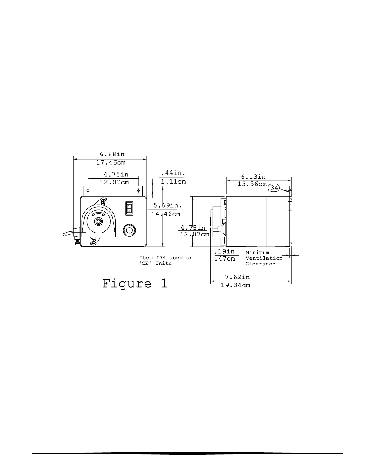
Dimensions: See Figure #1
Electrical Rating: Refer to name plate
Materials of Construction
Injection Fitting (standard w/check valve): PVC
Suction/Discharge Tubing: Polyethylene
Pump Housing: Chemical Resist Resin
INSTALLATION
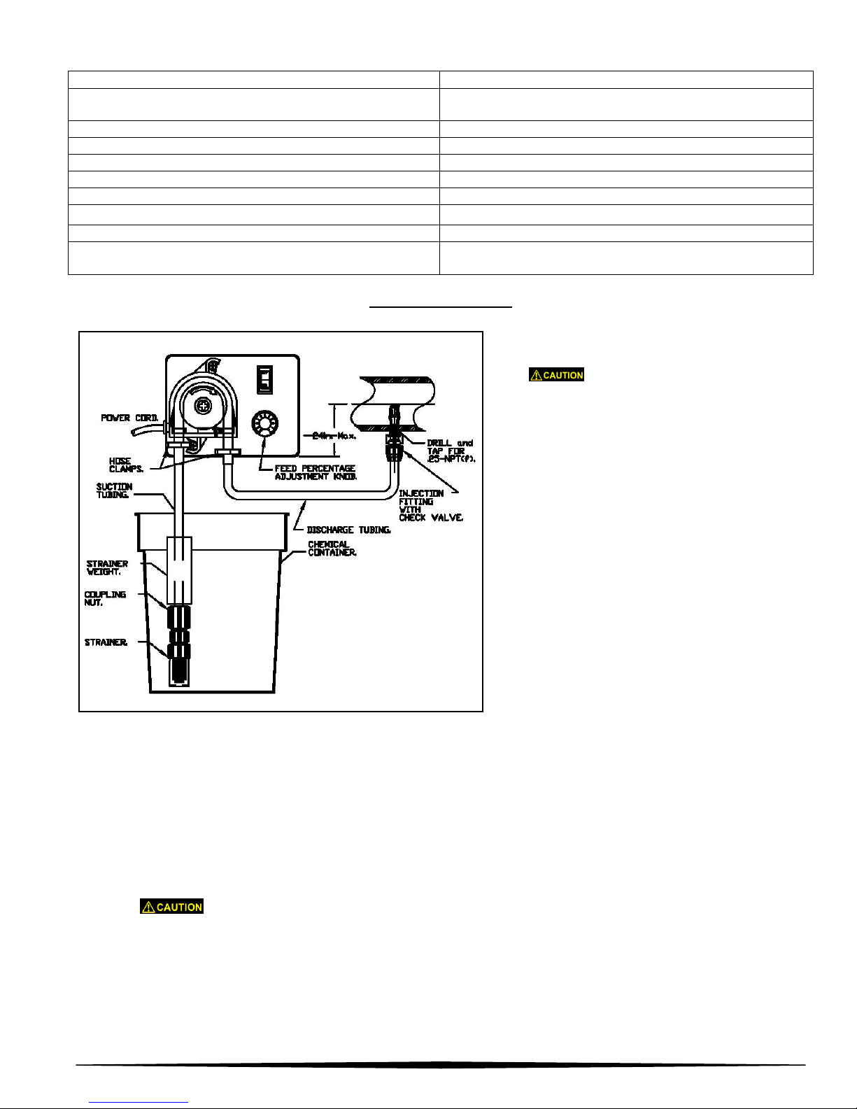
Figure #2
1. Mounting: Locate the feeder so there is
direct access to the power cord plug.
DO NOT POSITION SO THAT
COOLING VENTS IN THE REAR OF
THE CASE ARE OBSTRUCTED, .19in.
(4.7mm) minimum ventilation clearance
is required.
2. For ‘CE’ approved units the bracket
mount (Item #34 on page 2) must be
utilized for stationary mounting of pump.
3. Alternate mounting (not approved for
‘CE’): Set the feeder on a flat level
surface that will support its weight. The
feeder should be mounted on its 4 (four)
rubber feet (or use keyholes on back for
wall mounting (4.75in./12.60cm typical
spacing). Locate the feeder so there is
direct access to the power cord plug.
4. Electrical - Verify the electrical requirements for the pump as listed on the name plate and connect to
an appropriate electrical source in compliance with local codes for the specific application.
5. Injection Fitting - Relieve system pressure in the drain piping run where the injection fitting is to be
installed. See Figure #2. The injection fitting must not be installed in a dead end pipe or a deeply
recessed tee. It should be installed so as to place the tip at the center of the fluid stream. The
injection fitting has .25-NPT threads. If necessary drill a .44in.-diameter hole and using care not to tap
to deeply, tap for .25-NPT. Apply plumbers tape to the injection fitting threads and install into piping
system. DO NOT REMOVE THE PLASTIC SLEEVE ON THE TIP OF THE FITTING. It is a functional
part.
Inspect piping system and eliminate piping cross-connections to prevent feeding
chemical to areas not needing treatment.
6. Suction and Discharge Tubing - Take the 15-ft. (4.5m) length of .25in.-dia. tubing included, measure
and cut the lengths needed to run from the pump head to the injection fitting, and to the chemical tank
(Figure #2). Cut the tubing ends square.
7. Refer to maintenance section to install the pump head tubing.
4
Page 5
INSTALLATION (continued)
8. Connect discharge tubing to the injection
fitting-Remove the injection fitting nut slide it over
the end of the tubing. Push the end of the tubing
onto the injection fitting. Note: Immerse tubing in
hot water to soften prior to pushing on fitting.
Turn on and tighten the nut firmly, Hand tighten
only do not use wrenches.
9. Connect suction tubing to strainer - Install strainer
so it is off the bottom of the chemical container 1-2
inches (2.5-5cm) see Figure #3. Measure suction
tubing length required. Cut tubing end square and install on suction fitting of the pump. Hand tighten
only do not use wrenches.
Figure 3
OPERATION
1. Fill the chemical tank with the chemical you will feed.
2. Turn the feeder switch on to start the pump. Turn the feed percentage knob to “10”. It will begin to
feed chemical into the system when all tubing has filled.
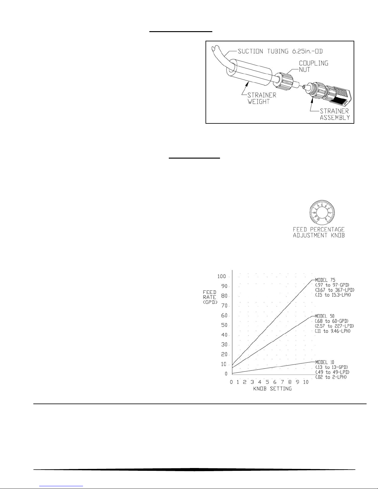
3. Set the feed percentage adjustment knob - Turn the knob to achieve the
desired feed rate, according to the chart shown in Figure #4. For example, to
feed approximately 34-gallons (128-liters) per day with the DOLPHIN-50, set the
knob at “5”.
4. The numbers on the dial represent minutes of run time within a 10-minute cycle. For example, a setting
of “3” will run the pump for approximately three minutes. This cycle will repeat as long as power is
supplied or unless the dial setting is changed. When feeder is turned on, the current setting will run a
complete cycle starting with the run time.
NOTE: To get actual feed rates for specific
settings, actual output must be verified by
measuring volume output. Use the flow chart as a
guide (Figure #4). To get actual feed rate for
specific setting each pump must be calibrated for
its flow. As with any peristaltic pump output varies
with pressure and tubing condition. It is
recommended that feed rate be verified at every
tubing change and after every 250-hours. More
critical applications require more frequent
verification.
Figure 4
Pumps carrying the ‘NSF’ seal or the ‘ETL Sanitation’ seal are listed for swimming pools, spas and hot
tubs, and when proper materials are selected, are capable of handling but not limited to the following
chemical solutions:
12% ALUMINUM SULPHATE, 5% SODIUM CARBONATE,
2% CALCIUM HYPOCHLORITE, 10% SODIUM HYDROXIDE,
12.5% SODIUM HYPOCHLORITE, 10% HYDROCHLORIC ACID.
5
Page 6
MAINTENANCE
NOTE: NO USER SERVICEABLE COMPONENTS INSIDE ENCLOSURE. SHOULD THE POWER
SUPPLY CORD BECOME DAMAGED, IT MUST BE REPLACED BY PULSAFEEDER or IT’S
REPRESENTATIVES or A SIMILARLY QUALIFIED PERSON IN ORDER TO AVOID A HAZARD.
Do not attempt to feed chemicals without consulting your chemical feeder dealer or
chemical supplier.
Filling the chemical tank - To avoid running out of chemical, follow a regular schedule of monitoring
chemical supply. Also inspect and clean the strainer by flushing with a compatible liquid, as needed.
Inspect peristaltic tubing frequently and replace when deterioration becomes apparent. Peristaltic
tubing will eventually wear and break if neglected. This occurrence will cause chemical spillage and
potential for personal injury or damage to equipment. If a potential hazardous or corrosive chemical is
handled, take precautions to prevent personal injury and damage in the event of tubing failure. Refer to
chemical manufacturer’s recommendations with regard to safety and handling precautions. Always wear
protective clothing and safety glasses when working near chemical feed systems.
Do not expose pump head tubing to pressure over 25-PSIG (1.76-kPa).
Tubing inspection: inspect all tubing regularly and replace it if deteriorating. Use the following instructions
to replace the pump head tubing.
Replacing pump head tubing:
Wear protective gloves, goggles and other adequate protection for the chemical hazard. Before
replacing the pump head, remove chemical from tubing as follows: Remove strainer from chemical tank,
then run feeder until all chemical is removed from the tubing.
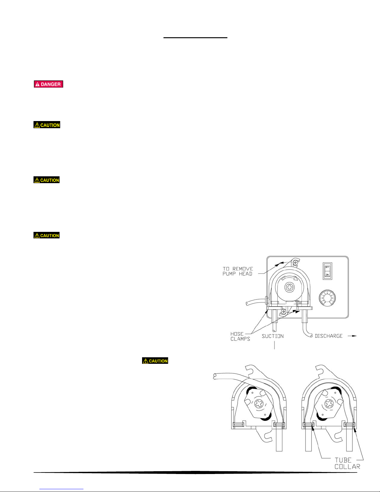
1. Remove the hose clamps from the tubing at the pump
head (twist clamp to disengage teeth).
2. Pull the suction and discharge tubing from the pump head
tubing.
3. Rotate the pump head counter-clockwise (see arrows in
Figure #5) to disengage from the collars on the feeder
cover. DO NOT REMOVE or LOOSEN COLLAR
SCREWS.
Figure 5
4. Grasp the tabs on the back cover of the pump head
and pull straight out to remove.
the bearing from the center hole in the back cover.
It’s not necessary to remove the spider and bearing
from the housing.
Do not lose
5. Remove the old tubing and retaining tube collars from the
pump head (Figure #6).
6. Position the spider about as shown in Figure #6. Then
put the retaining tube collar on the pump head tubing
as shown, and position the tube collar in the pump
head with the open end facing outward.
Figure 6
6
Page 7
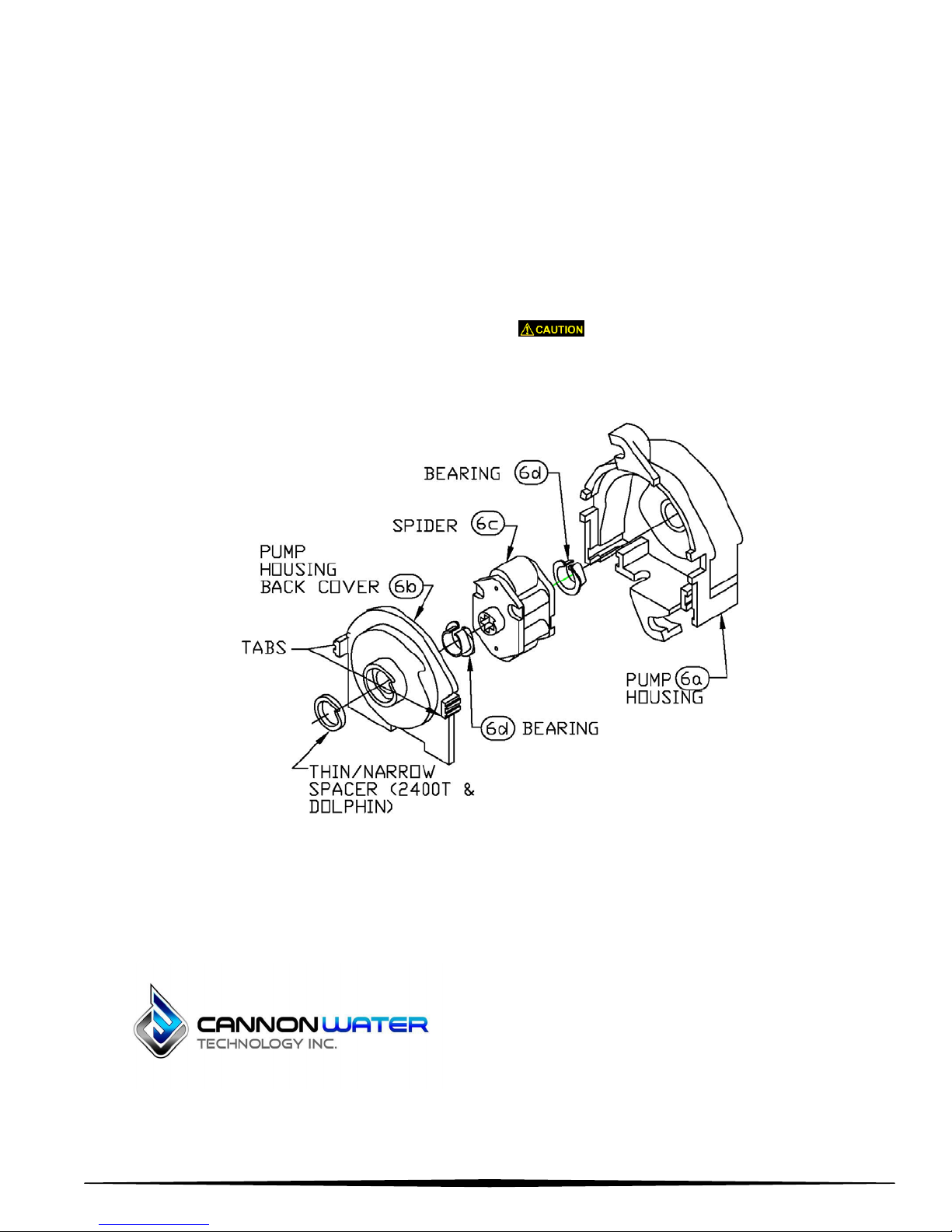
7. While rotating the spider counter-clockwise, push the tubing into the housing to center over the rollers
sales@novatech-usa.com
www.novatech-usa.com
Tel: (866) 433-6682 Fax: (866) 433-6684
Tel: (281) 359-8538 Fax: (281) 359-0084
as shown in Figure #6.
8. Replace the back cover on the pump head. Be sure it fits tightly against and flush w
ith the
housing (Figure #7).
9. Slide the pump head onto the motor drive shaft and turn it clockwise to lock onto the 2 (two) locking
collars.
10. Push the suction tubing and discharge tubing into the pump head tubing until they reach the bottom of
the pump head. Do not push the tubing past the tube collars. (See Figure #5). Install a hose clamp to
hold the tubing together. The hose clamp on the suction side should be as close as possible to the
pump head. Use pliers to squeeze the clamp tightly.
Hose clamps must be tightened
securely to prevent leakage, except when using .13in. I.D. Norprene tubing with barb fittings (no
clamps).
Figure 7
Cannon Water Technology Inc.
233 Technology Way Suite 9, Rocklin, CA 95765
Voice: 1 916-315-2691 FAX: 1 916-304-0210
https://cannonwater.com/
7
Page 8
 Loading...