

Page 1
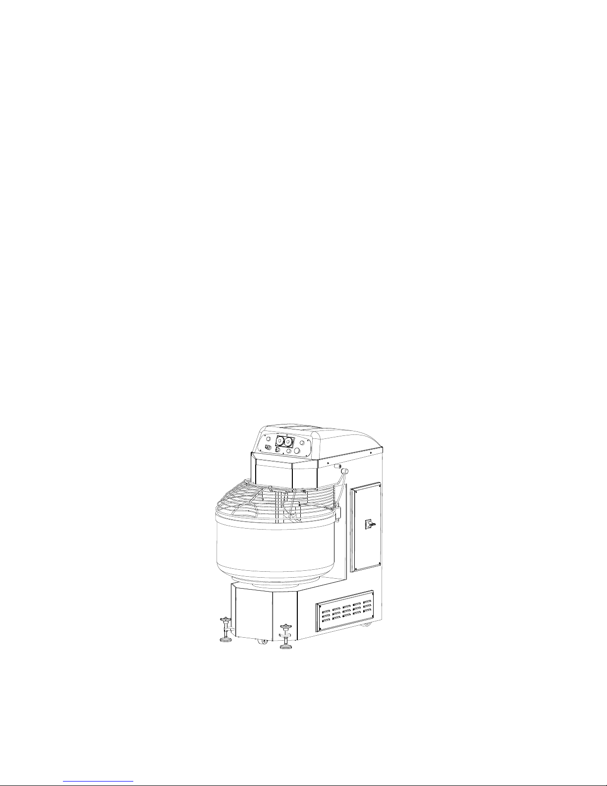
INSTRUCTION MANUAL
AUTOMATIC SPIRAL MIXER
SP60-80-100-130-160-200-250
SP80R-100R-130R-160R-200R-250R
Edition 10/2017
Page 2

2
INDEX
CHAPTER 1. GENERAL INFORMATIONS .................................................................. 4
1.1 PREFACE .................................................................................................................................................... 4
1.2 MACHINE IDENTIFICATION DETAILS ......................................................................................................... 4
1.3 WARRANTY ............................................................................................................................................... 4
1.4 MACHINE SPECIFICATIONS ....................................................................................................................... 4
1.4.1 TECHNICAL SPECIFICATIONS ............................................................................................................. 5
1.5 RELEVANT REGULATIONS ......................................................................................................................... 6
1.6 OPERATING AREA ..................................................................................................................................... 6
1.7 SAFETY AND HEALTH WARNINGS ............................................................................................................. 7
1.7.1 POWDERS RISK.................................................................................................................................. 8
1.7.2 SAFETY DEVICES ................................................................................................................................ 8
1.8 SERVICE AND SPARE PARTS ...................................................................................................................... 8
1.9 DEMOLITION OF THE MACHINE ............................................................................................................... 8
CHAPTER 2. INSTALLATION OF MACHINE ............................................................... 9
2.1 ENVIRONMENTAL CONDITIONS OF INSTALLATION SITE .......................................................................... 9
2.2 TRANSPORT AND HANDLING .................................................................................................................... 9
2.3 ADJUSTMENTS ....................................................................................................................................10
2.4 ELECTRICAL CONNECTIONS ....................................................................................................................10
CHAPTER 3. CONTROL DEVICES ............................................................................. 12
3.1 ELECTRO-MECHANICAL CONTROL PANEL ..............................................................................................12
CHAPTER 4. USE OF THE MACHINE ........................................................................ 13
4.1 TESTING ..................................................................................................................................................13
4.2 WORKING CYCLE DESCRIPTION ..............................................................................................................13
4.3 LOADING MACHINE ................................................................................................................................13
4.4 MACHINE START-UP ...............................................................................................................................14
4.5 MANUAL MODE ......................................................................................................................................14
4.5.1 MANUAL MODE AT 1
ST
SPEED .........................................................................................................14
4.5.2 MANUAL MODE AT 2 ND SPEED .......................................................................................................15
4.6 AUTOMATIC MODE.................................................................................................................................15
4.6.1 AUTOMATIC MODE – ONE SPEED ..................................................................................................15
4.6.2 AUTOMATIC MODO- TWO SPEEDS .................................................................................................16
4.7 STOPPING MACHINE ...............................................................................................................................17
4.8 DOUGH DISCHARGE ................................................................................................................................17
Page 3

3
CHAPTER 5. MAINTENANCE .................................................................................. 18
5.1 ORDINARY MAINTENANCE .....................................................................................................................18
5.1.1 CLEANING THE MACHINE ...............................................................................................................18
5.2 PROGRAMMED MAINTENANCE .............................................................................................................18
5.2.1 SPIRAL BELTS TENSION ADJUSTMENT ............................................................................................19
5.2.2 BOWL BELTS TENSION ADJUSTMENT .............................................................................................20
5.2.3 DOUBLE DRIVE TRANSMISSION BELTS TENSION ADJUSTMENT .....................................................20
5.2.4 SPIRAL BEARINGS REPLACE .............................................................................................................21
5.3 POSSIBLE FAILURE AND/OR ANOMALIES ...............................................................................................22
CHAPTER 6. LIST OF ENCLOSED DOCUMENTS ........................................................ 23
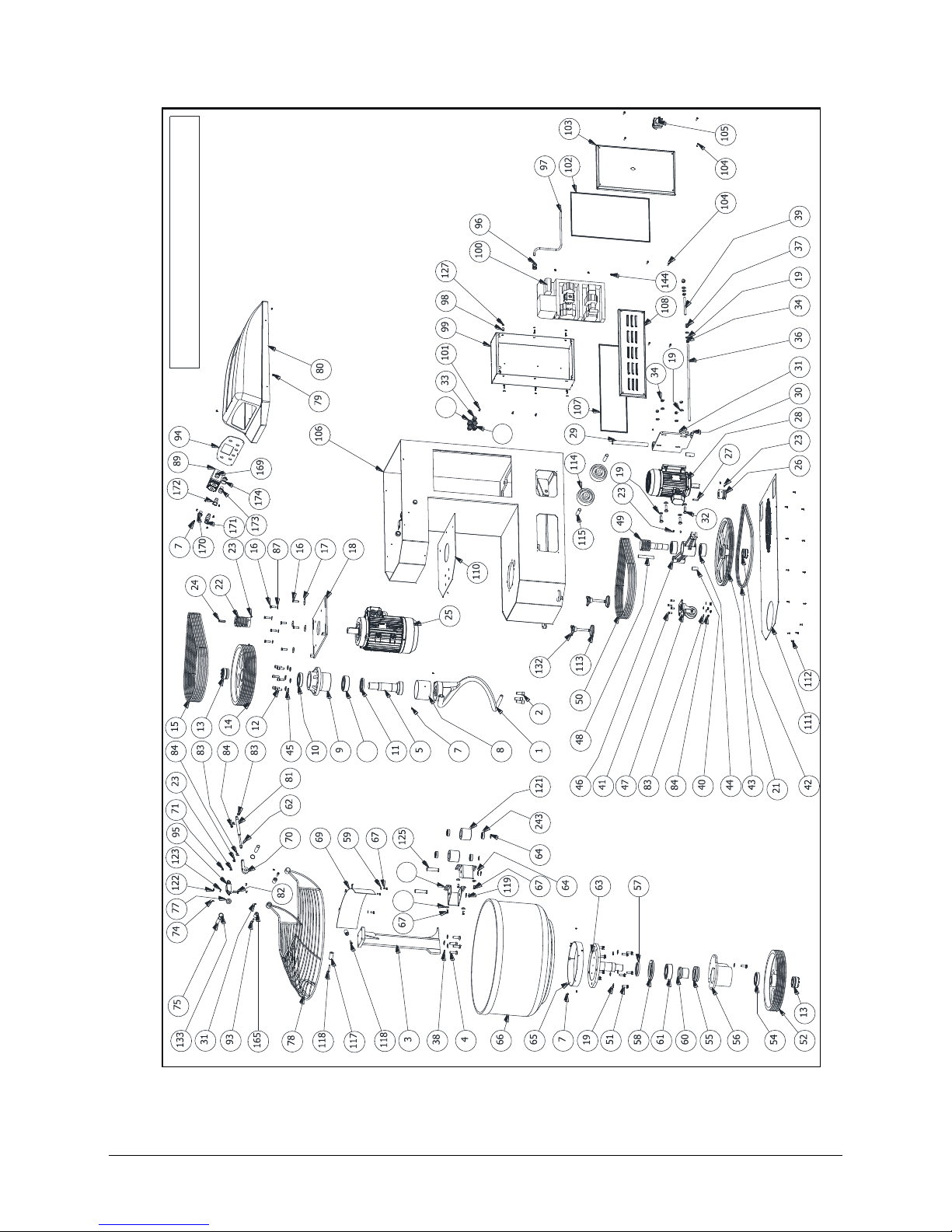
6.1 DRAWING SP 60-80-100-130-160-200-250 ...........................................................................................24
6.2 SPARE PARTS SP60- SP80- SP100- SP130- SP160- SP200- SP250 ..........................................................25
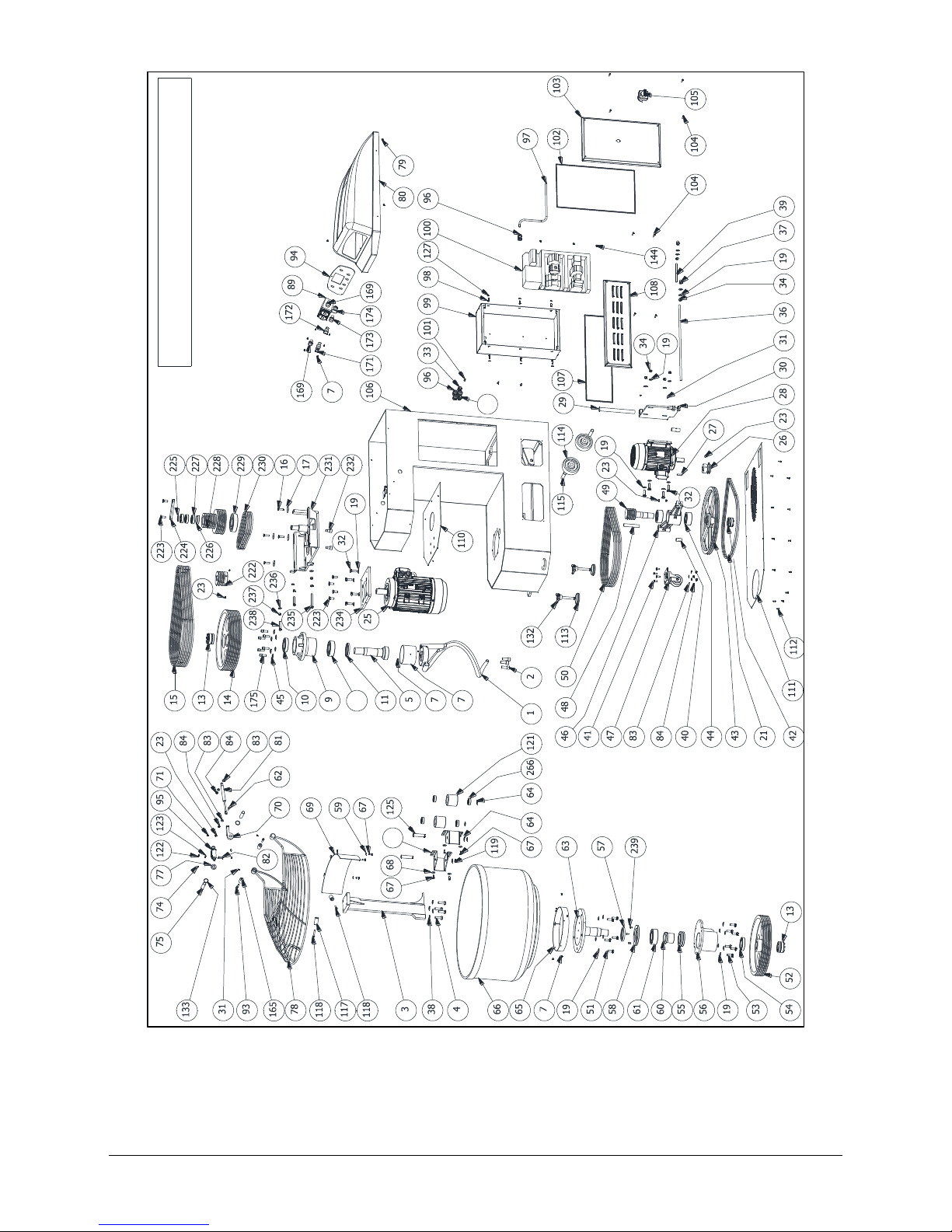
6.3 DRAWING SP 80R-100R-130R-160R-200R-250R....................................................................................28
6.4 SPARE PARTS SP80R- SP100R- SP130R-SP160R-SP200R-SP250R ..........................................................29
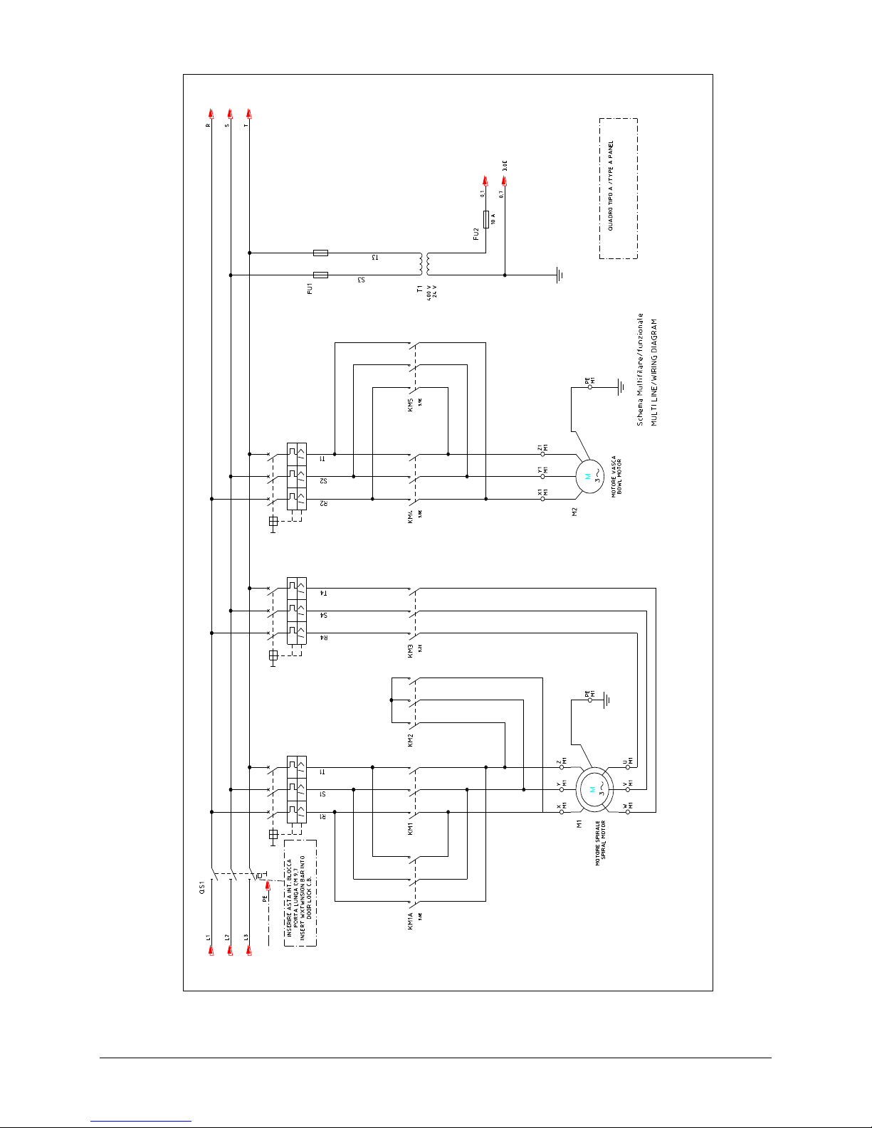
6.5 ELECTRICAL POWER SCHEME .................................................................................................................30
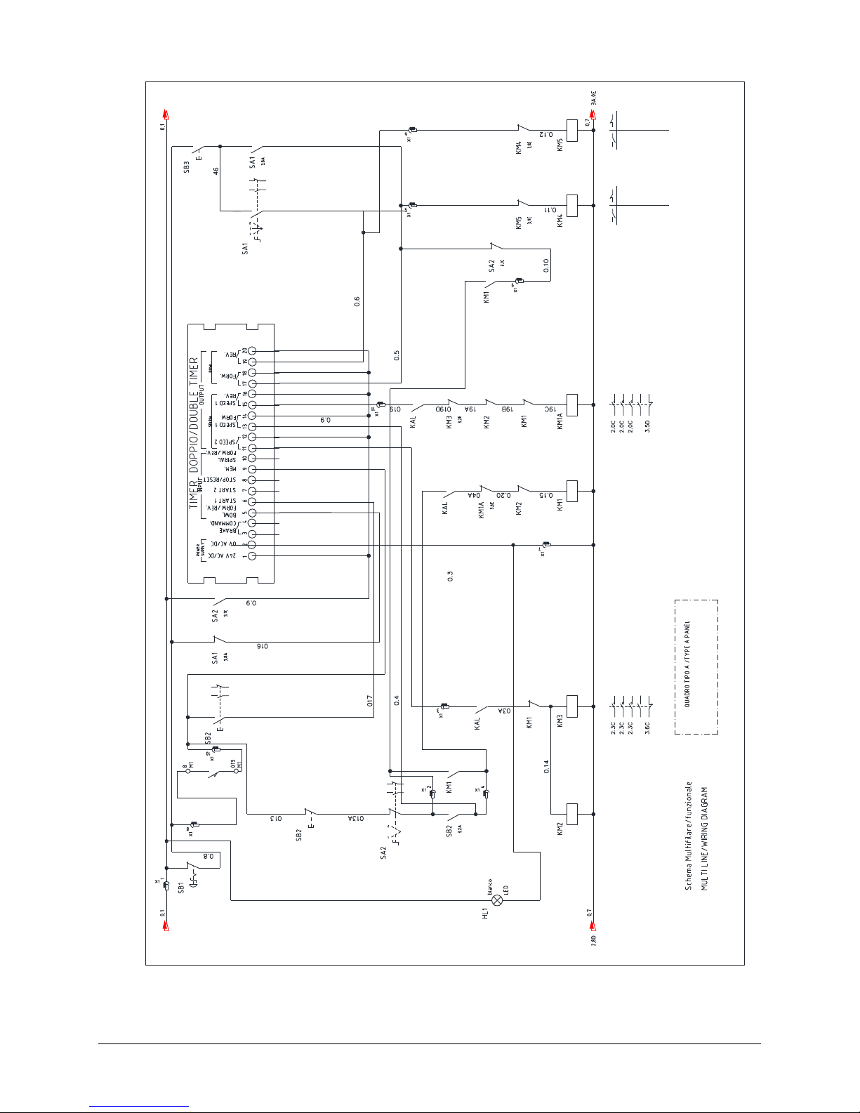
6.6 CONTROL CIRCUITS ................................................................................................................................30
6.7 CONTACTS ...............................................................................................................................................30
Page 4
4
CHAPTER 1. GENERAL INFORMATIONS
1.1 PREFACE
This manual is directed towards those who install, operate and maintain the machine so that they can take
advantage of the characteristics of the product in the best way. It is important that this manual is kept and
remains with the machine if it is moved or if ownership changes so that it can be consulted under all
circumstances and therefore the necessary information is available to operate it within safe conditions.
The manufacturer does not take upon themselves the obligation to give notice of possible successive
modifications of the product. Furthermore, under the terms of law, this document remains the property of the
manufacturer, and tampering, reproduction or transmission to a third party are prohibited without their
consent.
The following symbols are used to better stress some passages
ATTENTION: indicates hazards that might cause serious damages; attention is required
NOTE: indicates particularly important technicial information
1.2 MACHINE IDENTIFICATION DETAILS
The identification data of the machine are impressed on the plate placed on the rear of the machine.
MODEL
__________
SERIAL NUMBER
__________
DATE OF MANUF.
__________
VOLTAGE
__________
FREQUENCY
__________
PHASE
__________
AMPS
__________
1.3 WARRANTY
The duration of the guarantee is for two years and runs from the date on the invoice or tax receipt was issued
at the time of purchase. Within this period, components that have been unequivocally ascertained to be faulty
due to manufacturing defects will be substituted or repaired freely by the manufacturer from their premises,
except for electrical components and those subject to wear and tear.The guarantee excludes postage and
labour costs.
The guarantee is forfeited in the case of the damage being caused by: transportation, wrong or insufficient
maintenance, unskilled operators, tampering, repairs carried out by unauthorised personnel, or failure to
comply with the instructions of the manual. Compensation from the manufacturer will not be given for direct
or indirect damages arising during any time the machine is inoperative due to its breakdown, it being awaiting
repairs, or in any way referable to the non- physical presence of the machine.
1.4 MACHINE SPECIFICATIONS
The machine has been built and designed for professional use in the bakery and pastry industry.
The working cycle can be manual or automatic with two speeds.
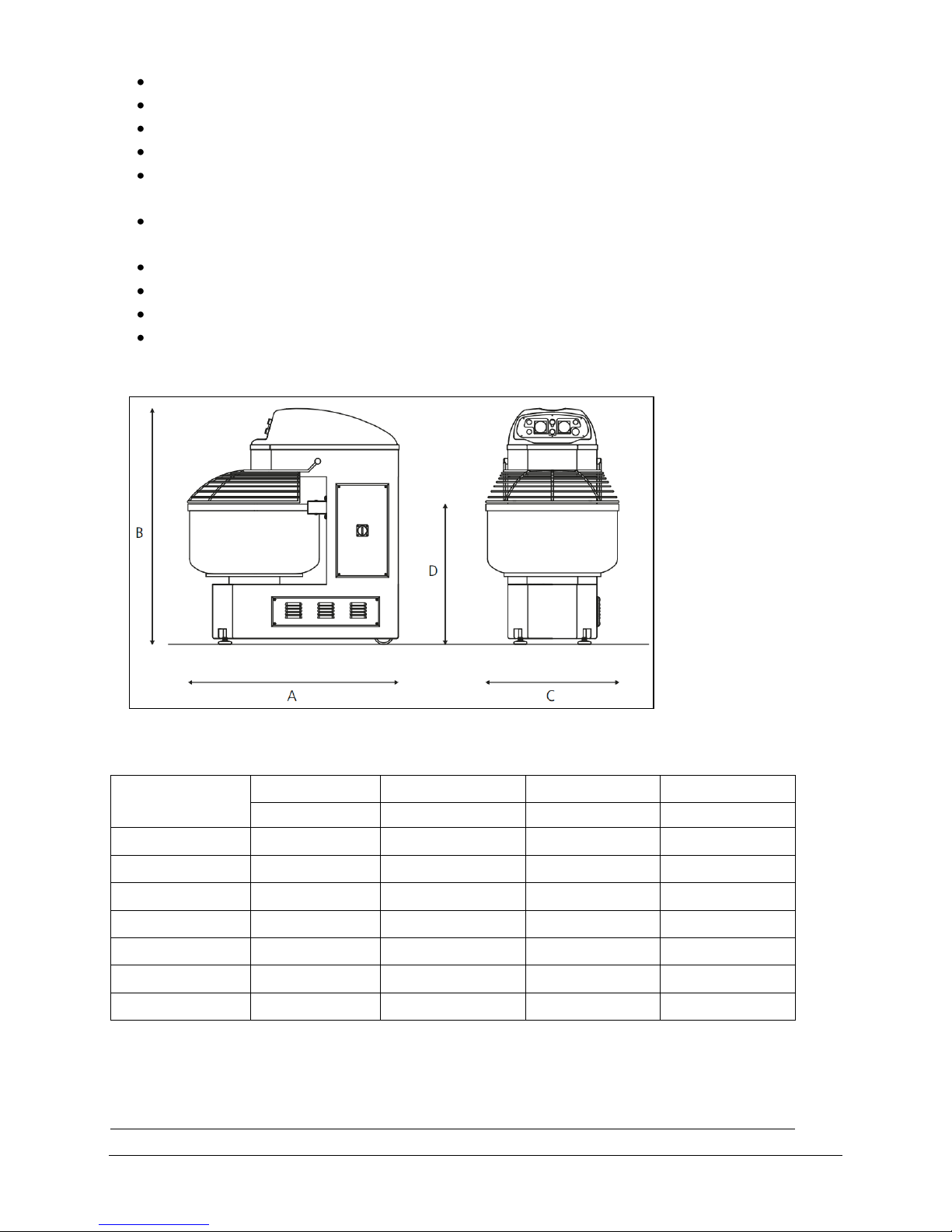
The machine (Pict.1.1) consists of:
Page 5
5
steel-bowl, spiral and shaft in strong high stainless steel
protection cover in stainless steel
head plate covered in stainless steel
machine can be equipped with two operating speeds automatically adjustable
two independent motors for spiral and bowl two electronic timers for an automatic management of
operating speeds
a bowl with rotation on impulse a predisposition for a flip-over mechanism on worktable or divider a
reversible bowl
a chain drive system made using trapezoidal belts to get the highest silence
front feet made in stainless steel and they are adjustable
rear wheels for an easy movement
electric system and the safety devices conform to the European regulations
Pict. 1.1 - Dimensions
Tab. 1.1 - Dimensions
Model
A B C
D
mm
mm
mm
mm
SP60-SP60R
1180
1312
630
800
SP80-SP80R
1305
1460
730
830
SP100-SP100R
1305
1460
730
850
SP130-SP130R
1355
1460
830
870
SP160-SP160R
1440
1560
930
870
SP200-SP200R
1490
1560
930
910
SP250-SP250R
1580
1560
1030
950
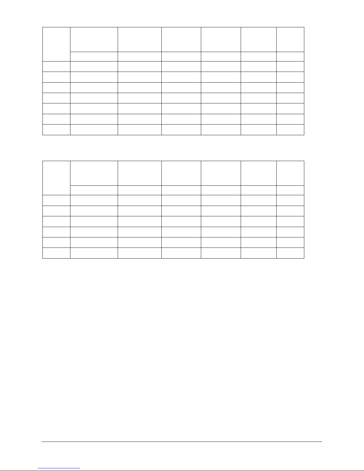
1.4.1 TECHNICAL SPECIFICATIONS
Tab. 1.2 – Tecnical specifications SP 60-80-100-130-160-200-250
Page 6
6
Model
Kneading capacity
Flour capacity
Bowl volume
Spiral motor
1th/2th speed
Bowl motor
Weight
kg
kg
Lt.
kW
kW
kg
SP60
60
40
100
1.5/3
0.55
370
SP80
80
53
130
3/5.2
0.75
510
SP100
100
66
160
3/5.2
0.75
520
SP130
130
86
200
3/5.2
0.75
580
SP160
160
106
250
4.5/7.8
1.1
790
SP200
200
133
290
6.5/11
1.1
830
SP250
250
166
390
6.5/11
1.1
860
Tab. 1.3 - Tecnical specifications SP 80R-100R-130R-160R-200R-250R
Model
Kneading capacity
Flour capacity
Bowl volume
Spiral motor
1th/2th speed
Bowl motor
Weight
kg
kg
Lt.
kW
kW
kg
SP80R
80
53
130
3.5/5.2
0.75
564
SP100R
100
66
160
3.5/5.2
0.75
565
SP130R
130
86
200
3.5/5.2
0.75
600
SP160R
160
106
250
4.5/7.5
1.1
795
SP200R
200
133
290
5.9/10.3
1.1
815
SP250R
250
166
390
5.9/10.3
1.1
870
1.5 RELEVANT REGULATIONS
The machine has been designed and manufactured in accordance with the Machinery Directive 2006/42/CE
and the following standards:
- UNI EN ISO14121-1: Safety of machinery
- UNI EN ISO12100: Safety of machinery - General principles for design
- UNI EN ISO13857: Safety distances
- UNI EN 349:2008: Minimum gaps to avoid crushing of parts of the human body
- IEC60204-1 Ed. 6.0: Electrical equipment of machines
- EN 453: Food Processing Machinery - Dough Mixers
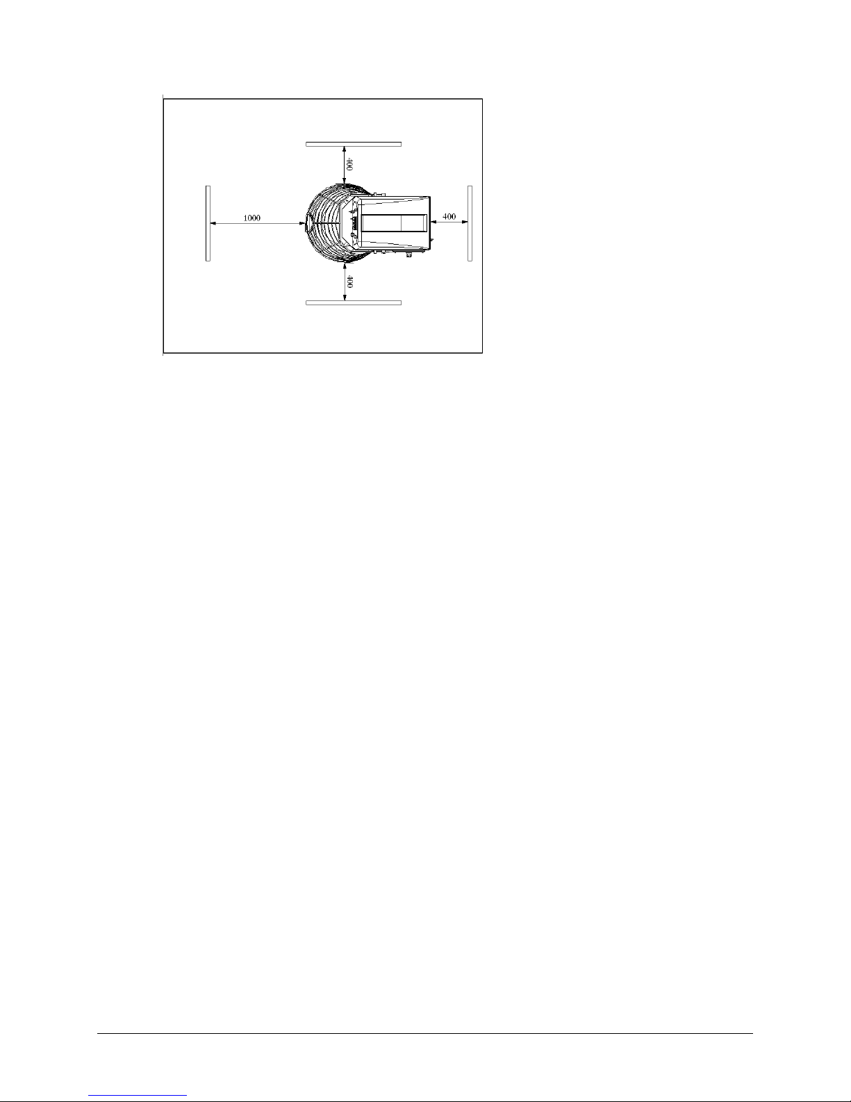
1.6 OPERATING AREA
In the normal working conditions and to have the best exploration of the potentiality of the machine, the
operator needs the area represented in Pict. 1.2
Page 7
7
Pict. 1.2: Operating area
1.7 SAFETY AND HEALTH WARNINGS
Although the machine is built in conformity to the required security rules regarding electrical, mechanical and
hygienic regulation it can be dangerous if:
·
Used in case and condition different to those described by the manufacturer.
·
Manomission of the protection and of the safety devices.
·
Innattention to the instruction of: Installation - Functioning - Usage - Maintenence.
In particular:
A) Do not use the machine in humid, wet or nadly lit environments, close to inflamable liquids or gas.
B) Keep away from children and non authorized personnel.
C) Only utilize the machine with the correct voltage. Normal usage gives better results.
D) Dress in adequate way. Do not wear hanging clothes or any items which can be caught in the machine.
Use non-slip shoes. For hygiene and safety keep your hair tied back and wear protective gloves.
E) Protect the cable. Do not pull the cable to extract the plug. Do not leave the cable near high
temperatures, sharp objects, water or solvents.
F) Take the plug out. When the machine is not in use, before cleaning, maintenance and moving it.
G) Check that the machine is not damaged. Before using the machine carefully check that all security devices
are working. Check that: the mobile parts are not blocked, there are not any parts damaged, all the parts
have been set up correctly and all the conditions that could influence the regular functioning of the
machine are in working order.
H) Repairing the machine by qualified personnel. The repairs can only be done by qualified people, using
original spare parts.
The manufacturer declines any responsibility for damages to people, animals or things caused by the non –
Page 8

8
observance or non-respect of instructions s for installation, use and maintenance contained in this manual.
1.7.1 POWDERS RISK
During the loading operations of the dry products in the bowl or during the normal working some hanged
dusts can be determined (for example flour dust).
The ingredients and the packaged products must be handled with care, reducing at minimum the height over
the bowl from which they are poured.
The packages must be opened with care in the bowl inferior part to promote the flour dust release in the less
possible time.
During the flour loading and during the machine functioning normal cycle, a suction centralized system
must be prepared and functioning, placed in the machine superior part.
In any case, against the residual risk due to the lacked functioning of the suction system, the operator and
the maintenance man besides to be adequately informed and trained, every time that approach in the working
zones, must use respiratory ways protection devices, as for example anti dust respiratory masks or other
suitable devices.
Besides, the working must be immediately interrupted and the internal maintenance service must be activated
to function the suction system.
The same individual protection devices must be used from the operator and from the maintenance man when
perform the machine cleaning operations.
1.7.2 SAFETY DEVICES
The machine is equipped with the following safety devices:
Safety guard which prevents access to the bowl during the work process
Emergency stop button
A microswitch which acts by stopping the machine during operation if the safety grill is lifted
Safety guard for the electrical system
1.8 SERVICE AND SPARE PARTS
For questions on service and spare parts please contact your local dealer and state the following information
(see data plate):
•
Type of machine
•
Year of production
•
Reference number of the required piece as indicated in the drawing enclosed).
Use only genuine spare parts.
1.9 DEMOLITION OF THE MACHINE
In case of dismantling and demolition of the machine, the pieces which the machine is made of, do not present
any kind of danger that necessitates any particular caution. To facilitate the recycling process, you must
separate the different parts according to material type and provide the scrapping in compliance with the
existing laws and regulations.
Page 9
9
CHAPTER 2. INSTALLATION OF MACHINE
The machine should be installed in a well-ventilated room protected from dust and direct contact with
atmospheric agents.
The machine must remain packed until the final installation at the place of employment.
2.1 ENVIRONMENTAL CONDITIONS OF INSTALLATION SITE
The environmental conditions in which the machine must be installed must follow these characteristics:
- Temperature: +5/+40° C, with the average temperature not exceeding 35°C over a period of 24 hours.
- Relative humidity: from 30% to 95% in the absence of condensation
- Water and heat sources at safe distance from the machine
- Well-dimensioned flat and stable surface
2.2 TRANSPORT AND HANDLING
The machine is delivered completely assembled and packaged with a fumigated wooden case and and fixed
onto a wooden-pallet.
Transport and handling of machine must be carried out under safety conditions using appropriate means of
transport.
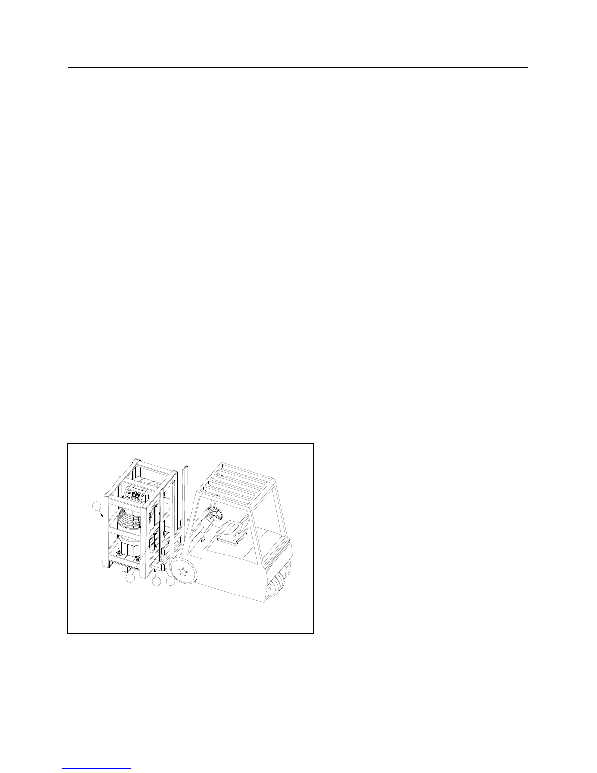
To lift and handle the pallet or the case use a suitable fork lift truck; the lifting forks are to be introduced in the
pallet as shown in Pict. 2.1 and 2.2.
Separate the different materials according to material type and recycle them in accordance with relevants
legislations.
Pict. 2.1
The machine is placed onto a wooden-pallet
(Pos.1) and it’s locked by a locking device (Pos.2)
and two threaded bars Pos. 3
The lifting forks are to be introduced in the
pallet as shown in Pict. 2.1 (Pos.4)
4
1
3
2
Page 10
10
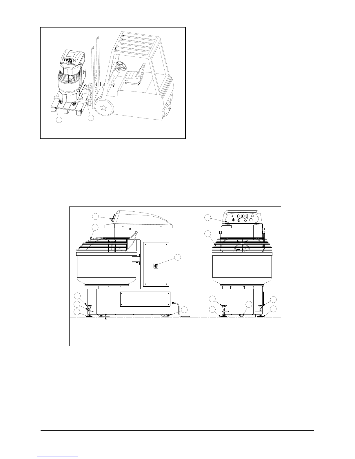
Pict. 2.2
Remove the docking device Pos. 2, introduce
the lifting forks Pos.4 as shown in Pict. 2.2 and
carefully lift the machine.
2.3 ADJUSTMENTS
After positioning in the selected area, adjust the front leveling feet Pos.51 Pict.2.3 with the3 lobe handwheel
Pos. 53 to get perfect leveling and then lock it by tightening the nut Pos. 52.
If the machine is unstable due to floor irregularity, adjust the support feet or wheels by inserting rubber pieces.
2.4 ELECTRICAL CONNECTIONS
The machine is equipped with connecting cable located on the back of the machine. It’s essential to mount a
normalised and polarised plug at the end of the cable.
1
51
53
52
4
2
3
2
4
51
54
53
51
53
7
4
1
Pict.2.3 : Installation
Page 11

11
ATTENTION: Before proceeding to the electrical connection, ensure that voltage and frequency are the same
declared by the Manufacturer and shown on the identification plate.
The electric net must be provided with an automatic differential switch and this has to be suitable to the
machine
The electrical plug must be easy to access, no moving should be necessary.
ATTENTION: Any electrical intervention involving the working site is to be carried out by qualified and
skilled technicians.. The manufacturer will not be liable for defects, breakdowns or
malfunctioning arising from the non-compliance with the power supply values stated.
Page 12
12
CHAPTER 3. CONTROL DEVICES
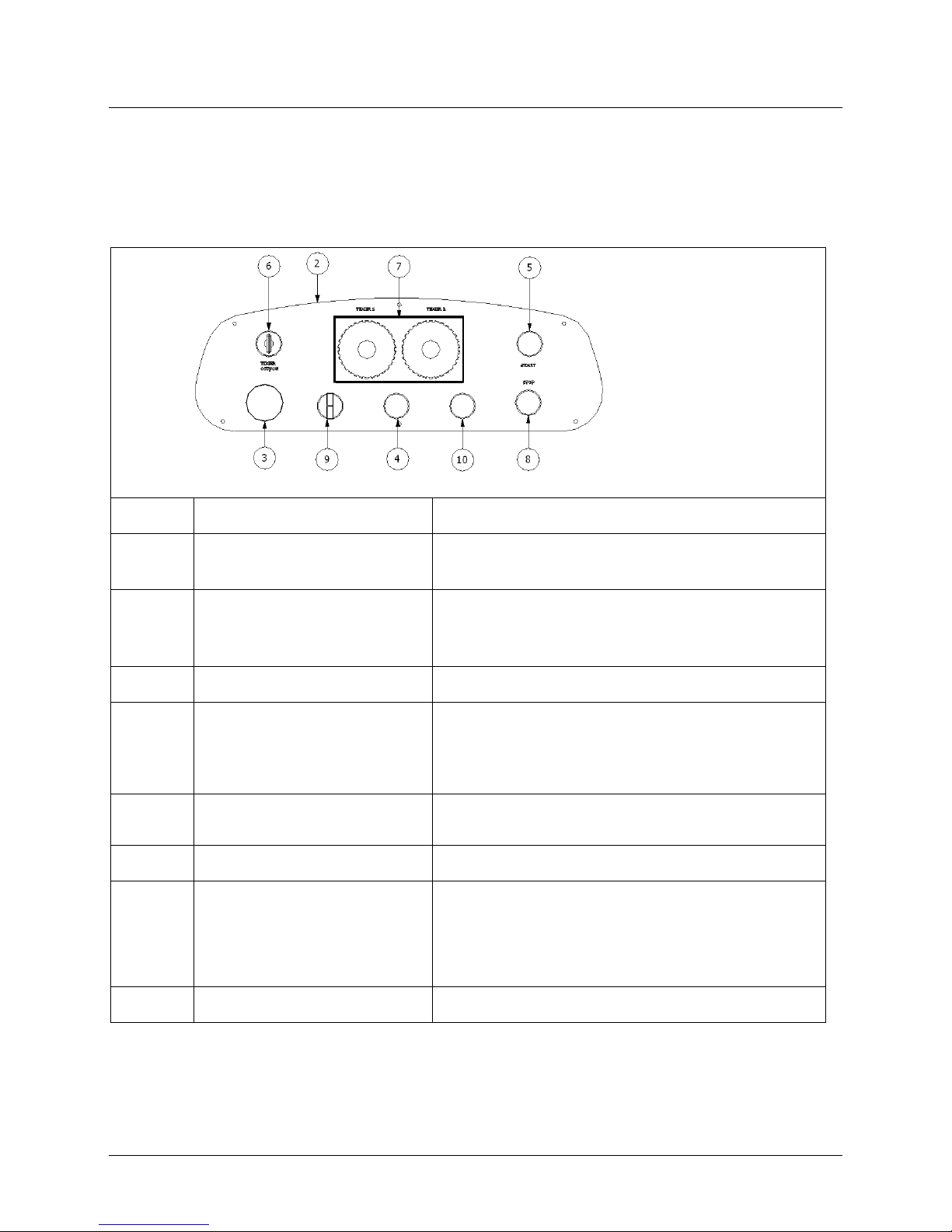
The control panel of the machine (Pict. 3.1) is placed in front of the machine and it includes all the necessary
push-buttons for its working /driving gears, planning of the dough times, reversal of the rotator movement of
the bowl)
3.1 ELECTRO-MECHANICAL CONTROL PANEL
Pict.3.1
POSITION
DESCRIPTION
FUNCTION
Pos.3
RED MUSHROOM EMERGENCY
BUTTON
When pressed, it stops the machine completely by cutting off the
voltage from the electric circuits.
Pos.4
INDICATOR LIGHT
After turning the main switch (look at Pict. 2.3, Pos. 3) to position “ I ” ,
if it lights, means that the machine is connected to the local electricity
network.
Pos.5
START BUTTON
To start the cycle
Pos.6
TIMER SWITCH OFF/ON
When turned to the left : manual operation cycle is enabled. (the timers
are excluded)
When turned to the right : automatic operation cycle is enabled.
Pos.7
TIMER 1 / TIMER 2
Timer 1: Controls time of 1st speed
Timer 2: Controls time of 2st speed
Pos.8
STOP BUTTON
Stop the machine
Pos.9
REVERSE BOWL ROTATION
SELECTOR
Left position: clockwise bowl rotation
Middle position: no bowl rotation
Right position: anticlockwise bowl rotation
Pos.10
JOGGING BUTTON
Jogs the bowl to help the dough extraction.
Page 13

13
CHAPTER 4. USE OF THE MACHINE
4.1 TESTING
Before starting the machine, the safety devices should be checked according to the following procedure:
1 while the machine is working, press the emergency button (Pos. 3 Pict.. 3.1). The machine should stop
immediately.
2 while the machine is working lift the protection grid(Pos. 4 Pict. 2.3). The machine should stop
immediately
Check that the control devices are functioning correctly, as described in the following paragraphs 4.4, 4.5, 4.6,
4.7.
Once the plug has been connected to the power supply socket, check the correctness of the bowl rotation
direction (look at the direction shown by the arrow on the bowl). If the rotation direction is not correct,
proceed as follows:
1. Stop the machine (Press STOP button Pos.8 Pict. 3.1 or the EMERGENCY BUTTON Pos.3 Pict. 3.1)
2. Take the plug out of the electric socket.
3. Reverse on the plug the position of two phases (example: L1 with L2 and vice versa).
4. Insert the plug into the electrical socket
5. Restart the machine and verify if the bowl is rotating the right way.
4.2 WORKING CYCLE DESCRIPTION
The dough phase consists of the following steps:
a) Loading machine
b) Execution of mixture cycle
c) Dough discharge
4.3 LOADING MACHINE
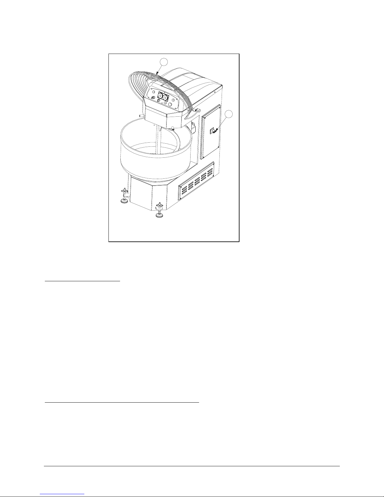
Lift up the protection grid Pos.4 Pict. 4.1
Put all initial ingredients into the bowl and then close the bowl cover. Always pour water in the bowl before
adding flour.
ATTENTION: Do not introduce into the bowl any quantity of ingredients exceeding the capacity given by the
Manufacturer in the present manual (look at Tab. 1.2 and 1.3). This might cause severe
damage to the machine and in particular to the motion transmission system.
ATTENTION: During loading of dry ingredients in the bowl, powder suspended can be determined. (e.g. flour
powder). Ingredients and packaged products must be handled with care by minimizing the
height above the bowl base from which they are poured.
Careful slitting of bags in the lower part of the bowl to allow dust free discharge of flour as far
as possible.
The manufacturer will be not responsible for any reasons and for any eventual damages caused from a nonobservance of the instructions given in the same.
Page 14
14
To add ingredients during the work cycle, lift up Mobile Protect Pos.4 Pict.4.1, add the ingredients, lower the
protection and press START.
Pict. 4.1
4.4 MACHINE START-UP
Before starting the machine:
1. Connect the feeling cable to the electric connection
2. Turn the main O- I switch (look at Pos. 3 Pict. 4.1) to position “ I ”.
3. Be sure the red mushroom emergency button (Pos. 3 Pict. 3.1) is not pressed; otherwise unlock it by
turning the mushroom button in the direction of rotation indicated by the arrow
4. Be sure that the protection grid is lowered onto the bowl.
NOTE: It's possible to reduce or increase the mixing time during machine operating
4.5 MANUAL MODE
4.5.1 MANUAL MODE AT 1
ST
SPEED
To work in manual mode at 1
st
speed, proceed as follows:
1. Position the selector Pos.6 (Pict. 3.1) in position OFF
2. Press the START button (Pos 5 - Pict. 3.1) to start with the 1
st
speed
3. Press the STOP button (Pos 8 - Pict. 3.1) to stop the working cycle
NOTE: The machine operates only in 1st speed; it is not possible to reverse the bowl rotation direction.
3
4
Page 15

15
ALTERNATIVELY, PROCEED AS FOLLOWS:
1. Position the selector Pos.6 (Pict. 3.1) in position ON
2. Rotate the Timer 1 knob to the M position (manual)
3. Decide the bowl rotation direction with the selector Pos.9 Pict. 3.1 (otherwise the bowl does not rotate)
4. Press the START button (Pos 5 - Pict. 3.1) to start with the 1
st
speed
5. Press the STOP button (Pos 8 - Pict. 3.1) to stop the working cycle.
NOTE: During the working cycle it is possible to reverse the rotation direction of the bowl through the
selector Pos. 9 (Pict. 3.1).
4.5.2 MANUAL MODE AT 2
ND
SPEED
To work in manual mode at 2
nd
speed, proceed as follows:
1. Position the selector Pos.6 (Pict.3.1) in position ON
2. Rotate the Timer 1 knob to the E position (Timer 1 excluded)
3. Rotate the Timer 2 knob to the M position (manual)
4. Turning the selector switch Pos. 9 (Pict.3.1) to the right (otherwise the bowl does not rotate)
5. Press the START button (Pos 5 - Pict.3.1) the machine start at 1
st
speed and switches automatically to
the 2nd speed after about 5 seconds
6. Press the STOP button (Pos 8 - Pict.3.1) to stop the working cycle
NOTE: It is not possible to reverse the rotation direction of the bowl when the machine is operating in 2
nd
speed
4.6 AUTOMATIC MODE
4.6.1 AUTOMATIC MODE – ONE SPEED
To work in automatic mode at 1
st
speed, proceed as follows:
1. Position the selector Pos.6 (Pict.3.1) in position ON
2. Rotate the Timer 1 knob clockwise (to the right) to desired time period
3. Rotate the Timer 2 knob clockwise (to the right) to the E position (Timer 2 excluded)
4. Decide the bowl rotation direction with the selector Pos.9 –Pict. 3.1 (otherwise the bowl does not rotate)
5. Press the START button (Pos 5 - Pict. 3.1) to start at 1
st
speed.
The machine will stop when the time has ended.
Page 16

16
NOTE: Through the selector Pos 9(Pict. 3.1), it is possible to reverse the rotation direction of the bowl.
To work in automatic mode at 2
nd
speed, proceed as follows:
1. Position the selector Pos.6 (Pict.3.1) in position ON
2. Rotate the Timer 1 knob clockwise (to the right) to the E position (Timer 1 excluded)
3. Rotate the Timer 2 knob clockwise (to the right) to desired time period
4. Turning the selector switch Pos. 9 (Pict.3.1) to the right (otherwise the bowl does not rotate)
5. Press the START button (Pos 5 - Pict.3.1) to start the machine; it starts with the 1
st
speed and switches
automatically to the 2nd speed after about 5 seconds
The machine will stop when the time has ended.
NOTE: It is not possible to reverse the rotation direction of the bowl when the machine is operating in 2
nd
speed
4.6.2 AUTOMATIC MODO- TWO SPEEDS
1. Position the selector Pos.6 (Pict.3.1) in position ON
2. Rotate the Timer 1 knob clockwise (to the right) to desired time period
3. Rotate the Timer 2 knob clockwise (to the right) to desired time period
4. Decide the bowl rotation direction with the selector Pos.9 – Pict.3.1 (otherwise the bowl does not rotate)
5. Press the START button (Pos 5 - Pict.3.1) to start the machine
When the time on the display of Timer 1 reaches the 0 , the machine switches automatically to the 2nd speed
and it will stop when the time has ended.
NOTE: It’s possible to reverse the rotation direction of the bowl when the machine is operating in 1st speed
NOTE: When the machine is operating in 2nd speed, the bowl rotates only if the selector switch Pos. 9
(Pict.3.1) is turned to the right.
NOTE: It is not possible to reverse the rotation direction of the bowl when the machine is operating in 2nd
speed
Page 17

17
4.7 STOPPING MACHINE
MANUAL MODE: Press STOP button Pos. 8 Pict. 3.1 or lift the protection grid
AUTOMATIC MODE: The machine will stop automatically at the end of the cycle (at the end of the time period
set)
EMERGENCY STOP: Press Emergency stop button ( red mushroom-headed button) Pos. 3 (Pict. 3.1).
If the AUTOMATIC MODE is selected, when pressing the red mushroom emergency button (Pos. 3 Pict. 3.1),
the timer will reset.
When pressing the STOP button (Pos.8-Pict.3.1), the timer will not reset, and you can resume
working by pressing the START button (Pos.5-Pict. 3.1)
4.8 DOUGH DISCHARGE
After stopping the machine, let the bowl and spiral come to a complete rest.
Turn the main 0-I switch Pos.3 Pict.4.1 to position “ I ” and empty the bowl.
Page 18

18
CHAPTER 5. MAINTENANCE
ATTENTION: Before you start clearing or servicing the machine, verify that power has been turned off.
In any case of malfunctioning or damage of the machine you must apply for authorized
assistance from the manufacturer.
Maintenance is divided into two categories: ordinary maintenance and programmed maintenance
5.1 ORDINARY MAINTENANCE
For ordinary maintenance we intend all the operations that can be done by the operator only after having read
carefully the instructions given in this section.
5.1.1 CLEANING THE MACHINE
Cleaning the machine at the end of each operating cycle is highly recommended.
For the good functioning of the machine and for hygienic purposes, it is necessary to remove the dough crusts
from the bowl, the guard, the central column and the spiral by means of a cleaning cloths soaked in water or
appropriate detergent. If needed, try to remove the hardest remains by means of a plastic paddle.
ATTENTION: During the cleaning operations some dusts can be determined (for example flour dust); it's
recommended to use an extractor.
ATTENTION: Never use steel wool, compressed air jets or abrasive products to clean the machine.
ATTENTION: Do not use water jets to clean both the control panel and the electric board.
5.2 PROGRAMMED MAINTENANCE
Ordinary maintenance operations must only be carried out by qualified personnel.
These are periodic inspections in order to prevent any future failure and to maintain the machines security
standards
Particular attention must be paid to the belts tensioning.
The tension and general condition of the belt should therefore be checked at least monthly
Page 19
19
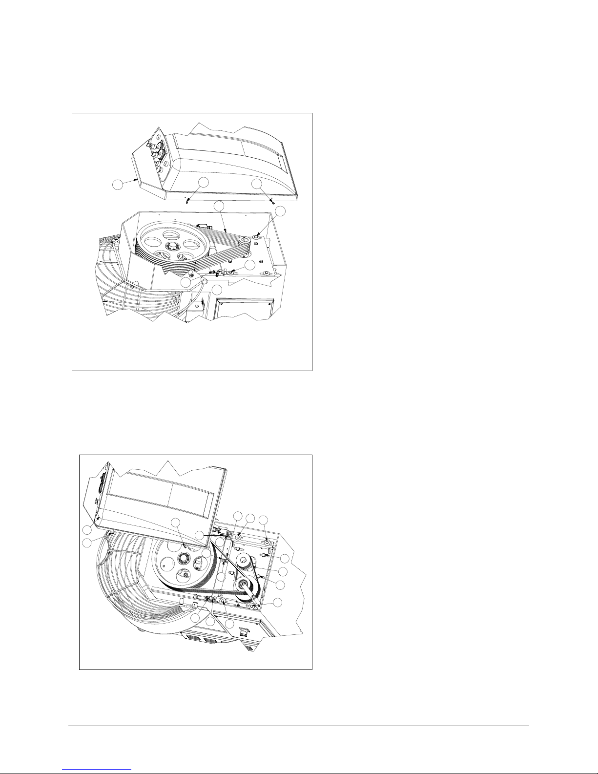
5.2.1 SPIRAL BELTS TENSION ADJUSTMENT
5.2.1.1 MOD. SP60,SP80,SP100,SP130,SP160, SP200,SP250
Proceed as follows:
1. Unscrew the screws Pos.6
2. Remove the head cover Pos.5
3. Loosen the four screws Pos.2 that sustain the
motor without unscrewing them completely
4. Loosen the nut Pos.3
5. Restore the correct belts tension with the
screw Pos.4
6. Retighten the screw Pos.3
7. Retighten the screws Pos.2 previously
loosened
8. Re-assemble the head cover Pos.1
5.2.1.2 MOD. SP80R,SP100R,SP130R,SP160R,SP200R,SP250R
Proceed as follows:
1. Unscrew the screws Pos.2
2. Remove the head cover Pos.1
3. Loosen the four screws Pos.3 without
unscrewing them completely
4. Loosen the nut Pos.5
5. Restore the correct belts tension with the
screw Pos.4
6. Retighten the screw Pos.5
7. Retighten the screws Pos.3 previously
loosened
8. Re-assemble the head cover Pos.1
1
2
2
3
4
5
6
6
Pict5.1: Spiral belts SP 60-80-100-130-160-200-250
1
2
2
3
3
5
4
6
6
9
7
8
4
5
3
3
10
Pict.5.2: Spiral belts SP 80R-100R-130R-160R-200R-250R
Page 20
20
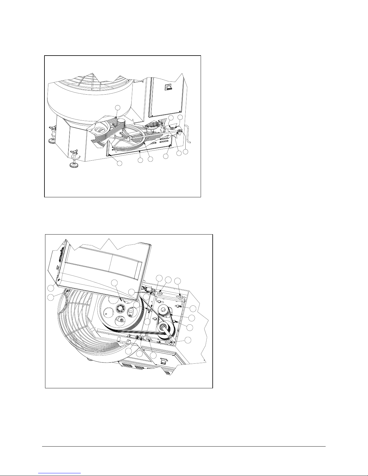
5.2.2 BOWL BELTS TENSION ADJUSTMENT
Proceed as follows:
1. Unscrew the four screws Pos. 3
2. Disassemble the side cover Pos.4
3. To adjust the tension of belts Pos.1,
loosen the nut Pos.6 and turn the nut
Pos.8
4. To adjust the tension of belts Pos.1,
loosen the nut Pos.6 and turn the nut
Pos.7
5. Re-assemble the head cover Pos.4
5.2.3 DOUBLE DRIVE TRANSMISSION BELTS TENSION ADJUSTMENT
Proceed as follows:
1. Unscrew the screws Pos.2)
2. Remove the head cover Pos.1
3. Loosen the four screws Pos.6 that
sustain the motor without unscrewing
them completely
4. Loosen the nut Pos.8
5. Restore the correct belts tension with
the screw Pos.7
6. Retighten the screw Pos.8
7. Retighten the screws Pos.6 previously
loosened
8. Re-assemble the head cover Pos.1
1
2
2
3
3
5
4
6
6
9
7
8
4
5
3
3
10
2
1
4
3
7
5
8
6
3
Pict.5.3: Bowl belts
Pict. 5.4: Double drive belts
Page 21
21
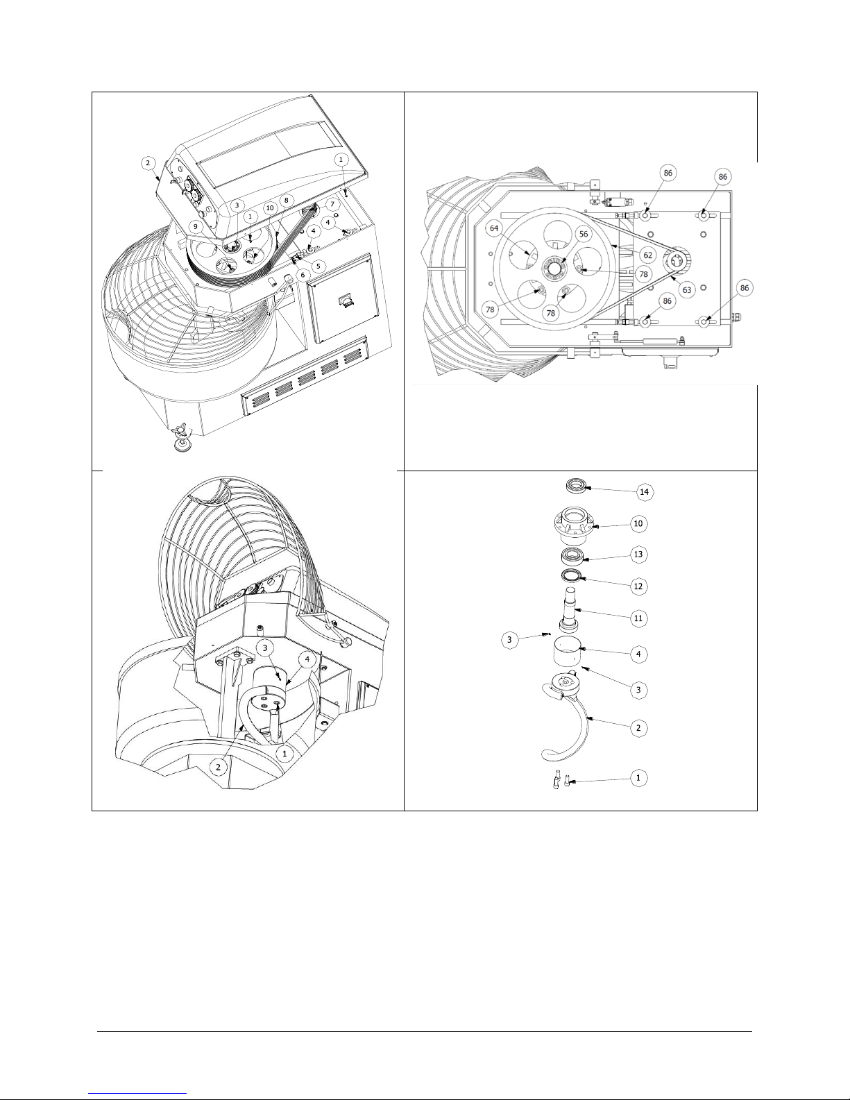
5.2.4 SPIRAL BEARINGS REPLACE
Proceed as follows:
1. Unscrew the screws Pos.2 and Remove the head cover Pos.1 (look at the Pict. 5.5)
2. Loosen the four nuts Pos.4(look at the Pict. 5.5)
3. Loosen the nuts Pos.5 (look at the Pict. 5.5) to loosen the belts tension
4. Unscrew the screws Pos.56 (look at Pict. 5.6) and remove the piece (Pos. 13 in the drawing enclosed)
5. Remove the pulley Pos. 62 (look at Pict. 5.6)
6. Unscrew the screws Pos.1 and remove the spiral Pos.2 (look at Pict. 5.7)
Pict.5.5
Pict.5.6
Pict. 5.7
Pict. 5.8
Page 22

22
7. Unscrew the screws Pos.3 and remove the piece Pos.4 (look at Pict. 5.7)
8. Unscrew the screws Pos.78 (look at Pict. 5.7) than remove the element (look at Pict. 5.8) composed of
pieces Pos. 10, Pos. 11, Pos. 12, Pos. 13
9. Remove the piece Pos. 11 (look at Pict. 5.8) and replace the bearings.
5.3 POSSIBLE FAILURE AND/OR ANOMALIES
ANOMALY
POSSIBLE CAUSE
POSSIBLE REMEDY
By pressing the key
start, the machine
does not start
Mancanza di energia
elettrica nella rete
Verificare il contatore generale, la presa, la spina
e il cavo di alimentazione
Emergency button
pressed
Re-set the emergency button in turning
it in clockwise direction.
Bowl cover lifted up
Close the cover bowl
Main power switch on
position “ O “
Turn the main O- I switch to position “ I ”.
Start button defective
Check and, if needed, replace the
defective parts.
During mixture cycle
phase spiral and/ or
bowl
slow down
The transmission belts
concerned are
loosen
Adjust the belt tension
The rotation direction
of the bowl is not
correct
The phases are inverted
Reverse on the plug the position of two phases
Page 23

23
CHAPTER 6. LIST OF ENCLOSED DOCUMENTS
6.1 –Drawing SP60-SP80-SP100-SP130-SP160-SP200-SP250
6.2 – Spare parts SP60-SP80-SP100-SP130-SP160-SP200-SP250
6.3 –Drawing SP80R-SP100R-SP130R-SP160R-SP200R-SP250R
6.4 - Spare parts SP80R-SP100R-SP130R-SP160R-SP200R-SP250R
6.5 - Power scheme
6.6 – Control circuit
6.7 - Contacts
Page 24
24
6.1 DRAWING SP 60-80-100-130-160-200-250
68
6
96
SP60/80/100/130/160/200/250
124
90
Page 25

25
6.2 SPARE PARTS SP60- SP80- SP100- SP130- SP160- SP200- SP250
POS
DESCRIZIONE
SP60
SP80
SP100
SP130
SP160
SP200
SP250
1
SPIRALE
SP060001
SPX80001
SPX80001
SP013001
SPX16001
SPX16001
SP025001
2
VITE
07112035
07116040
07116040
07116040
07116040
07116040
07116050
3
PIANTONE
SP060003
SPX80003
SPX80003
SP013003
SPX16003
SPX16003
SPX16003
4
VITE
07012050
07014045
07014045
07014045
07014045
07014045
07014045
5
ALBERO SPIRALE
SP060005
SPX80005
SPX80005
SPX80005
SPX16005
SPX16005
SP025005
6
CUSCINETTO
C32102RS
C32112RS
C32112RS
C32112RS
C33122RS
C33122RS
C33122RS
7
VITE
10406010
10406010
10406010
10406010
10406010
10406010
10406010
8
SCODELLINO SUPPORTO
SPIRALE
SP060008
SPX80008
SPX80008
SPX80008
SPX16008
SPX16008
SPX16008
9
SUPPORTO SPIRALE
SP060009
SPX80009
SPX80009
SPX80009
SPX16009
SPX16009
SPX16009
10
CUSCINETTO
C62102RS
C62112RS
C62112RS
C62112RS
C63122RS
C63122RS
C63122RS
11
ANELLO DI TENUTA
-
SPX80011
SPX80011
SPX80011
SPX16011
SPX16011
SPX16011
12
VITE
03212035
03212035
03212035
03212035
03212035
03212035
03212035
13
CALETTATORE
SPX60013
SPX80013
SPX80013
SPX80013
SPX16013
SPX16013
SPX16013
14
PULEGGIA SPIRALE
SP060014
SPX80014
SPX80014
SP013014
SPX16014
SPX16014
SP025014
15
CINGHIA SPIRALE
SP013050
SPX80015
SPX80015
SPX80015
SPX16015
SPX16015
SPX16015
16
VITE
02608030
02610040
02610040
02610040
02612040
02612040
02612040
17
RONDELLA
05410040
05410040
05410040
05410040
05410040
05410040
05410040
18
PIASTRA MOTORE
SPIRALE
SP060018
SPX80018
SPX80018
SPX80018
SPX16018
SPX16018
SPX16018
19
RONDELLA
05812000
05812000
05812000
05812000
05812000
05812000
05812000
21
CINGHIA VASCA
SP060041
SPX80015
SPX80015
SPX80015
SPX16041
SPX16041
SPX16041
22
PULEGGIA MOTORE
SPIRALE
SP060022
SPX80022
SPX80022
SP013022
SPX16022
SPX16022
SP025022
23
GRANO
03508014
03508014
03508014
03508014
03508014
03508014
03508014
24
LINGUETTA
CH080740
CH080740
CH080740
CH080740
CH128100
CH128100
CH128100
25
MOTORE SPIRALE
M2112003
M2132001
M2132001
M2132001
M2160003
M2160001
M2160003
26
PULEGGIA
SP060026
SPX80026
SPX80026
SPX80026
SPX16026
SPX16026
SP025026
27
LINGUETTA
CH070835
CH080740
CH080740
CH080740
CH080740
CH080740
CH080740
28
MOTORE VASCA
MT090004
MT100002
MT100002
MT100002
MT100003
MT100003
MT100003
29
ALBERO PIASTRA
MOTORE VASCA
SP060029
SPX80029
SPX80029
SPX80029
SPX80029
SPX80029
SPX80029
30
PIASTRA MOTORE VASCA
SP060030
SPX80030
SPX80030
SPX80030
SPX13030
SPX13030
SPX13030
31
GRANO
03508010
03508010
03508010
03508010
03508010
03508010
03508010
32
VITE
02610040
02612040
02612040
02612040
02612040
02612040
02612040
33
PRESSACAVO
PG135000
PG135000
PG135000
PG135000
PG135000
PG135000
PG135000
34
DADO
041M1200
041M1200
041M1200
041M1200
041M1200
041M1200
041M1200
36
BARRA TENSIONAMENTO
CINGHIE RINVIO
SP060036
SPX80036
SPX80036
SPX80036
SPX16036
SPX16036
SPX16036
37
DADO
079M1200
079M1200
079M1200
079M1200
079M1200
079M1200
079M1200
38
RONDELLA
05812000
05814000
05814000
05814000
05814000
05814000
05814000
39
BARRA TENSIONAMENTO
CINGHIE MOTORE
SP060039
SPX80039
SPX80039
SPX80039
SPX16039
SPX16039
SPX16039
40
CILINDRO FILETTATO
SPX60040
SPX60040
SPX60040
SPX60040
SPX60040
SPX60040
SPX60040
41
VITE
02608025
02608025
02608025
02608025
02608025
02608025
02608025
42
CALETTATORE
SP060042
SPX80042
SPX80042
SPX80042
SPX80042
SPX80042
SPX16051
43
PULEGGIA RINVIO
SP060043
SPX80043
SPX80043
SPX80043
SPX16043
SPX16043
SP025043
Page 26

26
POS
DESCRIZIONE
SP60
SP80
SP100
SP130
SP160
SP200
SP250
44
CUSCINETTO
C33082RS
C33082RS
C33082RS
C33082RS
C33082RS
C33082RS
C33082RS
45
MOLLA A TAZZA
064D1200
064D1200
064D1200
064D1200
064D1200
064D1200
064D1200
46
SUPPORTO RINVIO
SPX60046
SPX60046
SPX60046
SPX60046
SPX60046
SPX60046
SPX60046
47
RUOTA GIREVOLE
SPX60047
SPX60047
SPX60047
SPX60047
SPX60047
SPX60047
SPX60047
48
SPINOTTO SUPPORTO
RINVIO
SPX60048
SPX60048
SPX60048
SPX60048
SPX60048
SPX60048
SPX60048
49
ALBERO PULEGGIA
SP060049
SPX80049
SPX80049
SPX80049
SPX16049
SPX16049
SPX16049
50
CINGHIA
SP060050
SPX60015
SPX60015
SP013050
SPX80015
SPX80015
SPX80015
51
VITE
07112020
02612035
02612035
02612035
02612035
02612035
02612035
52
PULEGGIA VASCA
SP060014
SPX80014
SPX80014
SPX80014
SPX16014
SPX16014
SP025014
54
CUSCINETTO
C62092RS
C60122RS
C60122RS
C60122RS
C62142RS
C62142RS
C62142RS
55
CUSCINETTO
-
C5121400
C5121400
C5121400
C5121600
C5121600
C5121600
56
SUPPORTO VASCA
SP060056
SPX80056
SPX80056
SPX80056
SPX16056
SPX16056
SPX16056
57
ANELLO DI TENUTA
SP060057
SPX80057
SPX80057
SPX80057
SPX16057
SPX16057
SPX16057
58
FLANGIA
SP060058
SPX80058
SPX80058
SPX80058
SPX16058
SPX16058
SPX16058
59
RONDELLA
09008024
09008024
09008024
09008024
09008024
09008024
09008024
60
DISTANZIALE
-
SPX80060
SPX80060
SPX80060
SPX16060
SPX16060
SPX16060
61
CUSCINETTO
C62112RS
C32122RS
C32122RS
C32122RS
C32142RS
C32142RS
C32142RS
62
VITE
02608030
02608030
02608030
02608030
02608030
02608030
02608030
63
ALBERO SUPPORTO
VASCA
SP060090
SPX80063
SPX80063
SPX80063
SPX16063
SPX16063
SPX16063
64
SPESSORE
SPX40064
SPX40064
SPX40064
SPX40064
SPX40064
SPX40064
SPX40064
65
PROTEZIONE SUPPORTO
VASCA
SP060065
SPX80065
SPX80065
SPX80065
SPX16065
SPX16065
SPX16065
66
VASCA
SP060066
SP080066
SP010066
SP013066
SP016066
SP020066
SP025066
67
VITE
07008020
07008020
07008020
07008020
07008020
07008020
07008020
68
RONDELLA
09008024
09008024
09008024
09008024
09008024
09008024
09008024
69
PROTEZIONE VASCA
SP060069
SP080069
SP010069
SP013069
SP016069
SP020069
SP025069
70
LEVA AZIONAMENTO
MOLLA A GAS
SP060070
SPX80070
SPX80070
SPX80070
SPX80070
SPX80070
SPX80070
71
GRANO
03508010
03508010
03508010
03508010
03508010
03508010
03508010
74
GRANO
03506010
03506010
03506010
03506010
03506010
03506010
03506010
75
ALBERO GRIGLIA
SPX60075
SPX60075
SPX60075
SPX60075
SPX60075
SPX60075
SPX60075
77
AZIONATORE FINECORSA
SPX60077
SPX60077
SPX60077
SPX60077
SPX60077
SPX60077
SPX60077
78
GRIGLIA INOX
SP060078
SP080078
SP010078
SP013078
SP016078
SP020078
SP025078
79
VITE
10506010
10506010
10506010
10506010
10506010
10506010
10506010
80
CARTER TESTATA
SP060080
SPX80080
SPX80080
SPX80080
SPX16080
SPX16080
SPX16080
81
MOLLA A GAS
SP060081
SP060081
SP060081
SP060081
SP060081
SP060081
IMX12043
82
VITE
02604035
02604035
02604035
02604035
02604035
02604035
02604035
83
RONDELLA
05808000
05808000
05808000
05808000
05808000
05808000
05808000
84
DADO
050M0800
050M0800
050M0800
050M0800
050M0800
050M0800
050M0800
87
RONDELLA
05408024
05810000
05810000
05810000
05812000
05812000
05812000
89
TIMER DOPPIO
SPX60089
SPX60089
SPX60089
SPX60089
SPX60089
SPX60089
SPX60089
90
PRESSACAVO
PG110000
PG110000
PG110000
PG110000
PG110000
PG110000
PG110000
93
VITE
07108040
07108040
07108040
07108045
07108045
07108045
07108045
94
PANNELLO SERIGRAFATO
SP060094
SPX80094
SPX80094
SPX80094
SPX80094
SPX80094
SPX80094
95
MICROINTERRUTTORE
MIC00102
MIC00102
MIC00102
MIC00102
MIC00102
MIC00102
MIC00102
96
PRESSACAVO
PG160000
PG160000
PG160000
PG160000
PG160000
PG160000
PG160000
97
CAVO ELETTRICO
SPX60097
SPX60097
SPX60097
SPX60097
SPX16097
SPX16097
SPX16097
98
VITE
02606020
02606020
02606020
02606020
02606020
02606020
02606020
Page 27

27
POS
DESCRIZIONE
SP60
SP80
SP100
SP130
SP160
SP200
SP250
99
SCATOLA QUADRO
ELETTRICO
SP060099
SPX80099
SPX80099
SPX80099
SPX80099
SPX80099
SPX80099
100
IMPIANTO ELETTRICO
SP060167
SPX80167
SPX80167
SPX80167
SPX16167
SPX16167
SPX16167
101
VITE
02606020
02606020
02606020
02606020
02606020
02606020
02606020
102
GUARNIZIONE
SPX60102
SPX80102
SPX80102
SPX80102
SPX60102
SPX60102
SPX60102
103
CARTER QUADRO
ELETTRICO
SP060103
SPX80103
SPX80103
SPX80103
SPX80103
SPX80103
SPX80103
104
VITE
10406040
10406040
10406040
10406040
10406040
10406040
10406040
105
INTERRUTTORE
GENERALE
SP000105
SP000105
SP000105
SP000105
SP000105
SP000105
SP000105
106
TELAIO
SP060106
SPX80106
SPX80106
SPX80106
SPX16106
SPX16106
SP025106
107
GUARNIZIONE
SP060107
SPX80107
SPX80107
SPX80107
SPX80107
SPX80107
SPX80107
108
CARTER BASE
SP060108
SPX80108
SPX80108
SPX80108
SPX80108
SPX80108
SPX80108
110
PIASTRA TESTATA
SP060110
SPX80110
SPX80110
SPX80110
SPX16110
SPX16110
SP025110
111
CARTER INFERIORE
SP060111
SPX80111
SPX80111
SPX80111
SPX16111
SPX16111
SP025111
112
VITE
02005538
02005538
02005538
02005538
02005538
02005538
02005538
113
PIEDE LIVELLAMENTO
IMX60104
IMX60104
IMX60104
IMX60104
IMX60104
IMX60104
IMX60104
114
RUOTA POSTERIORE
IMX60013
SPX80114
SPX80114
SPX80114
SPX80114
SPX80114
SPX80114
115
MOZZO RUOTA
POSTERIORE
IM060141
SPX80115
SPX80115
SPX80115
SPX80115
SPX80115
SPX80115
117
FERMO GRIGLIA
SPX60117
SPX60117
SPX60117
SPX60117
SPX60117
SPX60117
SPX60117
118
VITE
07108050
07108050
07108050
07108050
07108050
07108050
07108050
119
SEEGER
051D1600
051D1600
051D1600
051D2000
051D2000
051D2000
051D2000
121
RULLO VASCA
IMX60134
SPX80121
SPX80121
SPX80121
SPX80121
SPX80121
SPX80121
122
DADO
050M0400
050M0400
050M0400
050M0400
050M0400
050M0400
050M0400
123
RONDELLA
05804000
05804000
05804000
05804000
05804000
05804000
05804000
124
SUPPORTO RULLO VASCA
SP060124
SPX80124
SPX80124
SPX13124
SPX13124
SPX13124
SP025124
125
ALBERO SUPPORTO
RULLO VASCA
IM060133
SPX80125
SPX80125
SPX80125
SPX80125
SPX80125
SPX80125
127
RONDELLA
05406024
05406024
05406024
05406024
05406024
05406024
05406024
132
VOLANTINO
IMX60103
IMX60103
IMX60103
IMX60103
IMX60103
IMX60103
IMX60103
133
RONDELLA IN NYLON
SPX60133
SPX60133
SPX60133
SPX60133
SPX60133
SPX60133
SPX60133
144
DADO
050M0600
050M0600
050M0600
050M0600
050M0600
050M0600
050M0600
165
FERMO GRIGLIA
SPX80165
SPX80165
SPX80165
SPX80165
SPX80165
SPX80165
SPX80165
169
PULSANTE START
SP000169
SP000169
SP000169
SP000169
SP000169
SP000169
SP000169
170
SPIA LUMINOSA BIANCA
SP000170
SP000170
SP000170
SP000170
SP000170
SP000170
SP000170
171
SELETTORE TIMER ONOFF
SP000171
SP000171
SP000171
SP000171
SP000171
SP000171
SP000171
172
SELETTORE INVERSIONE
MOTO VASCA
SP000172
SP000172
SP000172
SP000172
SP000172
SP000172
SP000172
173
PULSANTE MOVIMENTO
VASCA AD IMPULSO
SP000173
SP000173
SP000173
SP000173
SP000173
SP000173
SP000173
174
FUNGO DI EMERGENZA
SP000174
SP000174
SP000174
SP000174
SP000174
SP000174
SP000174
243
CUSCINETTO
C62042RS
C62042RS
C62042RS
C62042RS
C62042RS
C62042RS
C62042RS
Page 28
28
6
SP80R/100R/130R/160R/200R/250R
124
90
6.3 DRAWING SP 80R-100R-130R-160R-200R-250R
Page 29

29
6.4 SPARE PARTS SP80R- SP100R- SP130R-SP160R-SP200R-SP250R
POS
DESCRIZIONE
SP80R
SP100R
SP130R
SP160R
SP200R
SP250R
1
SPIRALE
SPX80001
SPX80001
SP013001
SPX16001
SPX16001
SP025001
2
VITE
07116040
07116040
07116040
07116040
07116040
07116050
3
PIANTONE
SPX80003
SPX80003
SP013003
SPX16003
SPX16003
SPX16003
4
VITE TE
07014045
07014045
07014045
07014045
07014045
07014045
5
ALBERO SPIRALE
SPX80005
SPX80005
SPX80005
SPX16005
SPX16005
SP025005
6
CUSCINETTO
C32112RS
C32112RS
C32112RS
C33122RS
C33122RS
C33122RS
7
VITE
10406010
10406010
10406010
10406010
10406010
10406010
8
SCODELLINO SUPPORTO
SPIRALE
SPX80008
SPX80008
SPX80008
SPX16008
SPX16008
SPX16008
9
SUPPORTO SPIRALE
SPX80009
SPX80009
SPX80009
SPX16009
SPX16009
SPX16009
10
CUSCINETTO
C62112RS
C62112RS
C62112RS
C63122RS
C63122RS
C63122RS
11
ANELLO DI TENUTA
SPX80011
SPX80011
SPX80011
SPX16011
SPX16011
SPX16011
12
VITE
03212035
03212035
03212035
03212035
03212035
03212035
13
CALETTATORE
SPX80013
SPX80013
SPX80013
SPX16013
SPX16013
SPX16013
14
PULEGGIA SPIRALE
SPX80014
SPX80014
SP013014
SPX16014
SPX16014
SP025014
15
CINGHIA SPIRALE
SPX80015
SPX80015
SPX80015
SPX16015
SPX16015
SPX16015
16
VITE
02610040
02610040
02610040
02612040
02612040
02612040
17
RONDELLA
05410040
05410040
05410040
05410040
05410040
05410040
18
PIASTRA MOTORE SPIRALE
SPX80018
SPX80018
SPX80018
SPX16018
SPX16018
SPX16018
19
RONDELLA
05812000
05812000
05812000
05812000
05812000
05812000
21
CINGHIA VASCA
SPX060041
SPX80015
SPX80015
SPX16041
SPX16041
SPX16041
22
PULEGGIA MOTORE SPIRALE
SPX80022
SPX80022
SP013022
SPX16022
SPX16022
SP025022
23
GRANO
03508014
03508014
03508014
03508014
03508014
03508014
24
LINGUETTA
CH080740
CH080740
CH080740
CH128100
CH128100
CH128100
25
MOTORE SPIRALE
M2112003
M2132001
M2132001
M2132001
M2160003
M2160001
26
PULEGGIA MOTORE VASCA
SPX80026
SPX80026
SPX80026
SPX16026
SPX16026
SP025026
27
LINGUETTA
CH070835
CH080740
CH080740
CH080740
CH080740
CH080740
28
MOTORE VASCA
MT090004
MT100002
MT100002
MT100002
MT100003
MT100003
29
ALBERO PIASTRA MOTORE
VASCA
SPX80029
SPX80029
SPX80029
SPX80029
SPX80029
SPX80029
30
PIASTRA MOTORE VASCA
SPX80030
SPX80030
SPX80030
SPX13030
SPX13030
SPX13030
31
GRANO
03508010
03508010
03508010
03508010
03508010
03508010
32
VITE
02612040
02612040
02612040
02612040
02612040
02612040
33
PRESSACAVO
PG135000
PG135000
PG135000
PG135000
PG135000
PG135000
34
DADO
041M1200
041M1200
041M1200
041M1200
041M1200
041M1200
36
BARRA TENSIONAMENTO
CINGHIE RINVIO
SPX80036
SPX80036
SPX80036
SPX16036
SPX16036
SPX16036
37
DADO
079M1200
079M1200
079M1200
079M1200
079M1200
079M1200
38
RONDELLA
05814000
05814000
05814000
05814000
05814000
05814000
39
BARRA TENSIONAMENTO
CINGHIE MOTORE
SPX80039
SPX80039
SPX80039
SPX16039
SPX16039
SPX16039
40
CILINDRO FILETTATO
SPX60040
SPX60040
SPX60040
SPX60040
SPX60040
SPX60040
41
VITE
02608025
02608025
02608025
02608025
02608025
02608025
42
CALETTATORE
SPX80042
SPX80042
SPX80042
SPX80042
SPX80042
SPX16051
43
PULEGGIA RINVIO
SPX80043
SPX80043
SPX80043
SPX16043
SPX16043
SP025043
44
CUSCINETTO
C33082RS
C33082RS
C33082RS
C33082RS
C33082RS
C33082RS
45
MOLLA A TAZZA
064D1200
064D1200
064D1200
064D1200
064D1200
064D1200
46
SUPPORTO RINVIO
SPX60046
SPX60046
SPX60046
SPX60046
SPX60046
SPX60046
Page 30

30
POS
DESCRIZIONE
SP80R
SP100R
SP130R
SP160R
SP200R
SP250R
47
RUOTA GIREVOLE
SPX60047
SPX60047
SPX60047
SPX60047
SPX60047
SPX60047
48
SPINOTTO SUPPORTO RINVIO
SPX60048
SPX60048
SPX60048
SPX60048
SPX60048
SPX60048
49
ALBERO PULEGGIA
SPX80049
SPX80049
SPX80049
SPX16049
SPX16049
SPX16049
50
CINGHIA
SPX60015
SPX60015
SP013050
SPX80015
SPX80015
SPX80015
51
VITE
02612035
02612035
02612035
02612035
02612035
02612035
52
PULEGGIA
SPX80014
SPX80014
SPX80014
SPX16014
SPX16014
SP025014
54
CUSCINETTO
C60122RS
C60122RS
C60122RS
C62142RS
C62142RS
C62142RS
55
CUSCINETTO
C5121400
C5121400
C5121400
C5121600
C5121600
C5121600
56
SUPPORTO VASCA
SPX80056
SPX80056
SPX80056
SPX16056
SPX16056
SPX16056
57
ANELLO DI TENUTA
SPX80057
SPX80057
SPX80057
SPX16057
SPX16057
SPX16057
58
FLANGIA
SPX80058
SPX80058
SPX80058
SPX16058
SPX16058
SPX16058
59
RONDELLA
09008024
09008024
09008024
09008024
09008024
09008024
60
DISTANZIALE
SPX80060
SPX80060
SPX80060
SPX16060
SPX16060
SPX16060
61
CUSCINETTO
C32122RS
C32122RS
C32122RS
C32142RS
C32142RS
C32142RS
62
VITE
02608030
02608030
02608030
02608030
02608030
02608030
63
ALBERO SUPPORTO VASCA
SPX80063
SPX80063
SPX80063
SPX16063
SPX16063
SPX16063
SPX16063
SPX16063
SPX16063
64
SPESSORE
SPX40064
SPX40064
SPX40064
SPX40064
SPX40064
SPX40064
65
PROTEZIONE SUPPORTO VASCA
SPX80065
SPX80065
SPX80065
SPX16065
SPX16065
SPX16065
66
VASCA
SP080066
SP010066
SP013066
SP016066
SP020066
SP025066
67
VITE
07008020
07008020
07008020
07008020
07008020
07008020
68
RONDELLA
09008024
09008024
09008024
09008024
09008024
09008024
69
PROTEZIONE VASCA
SP080069
SP010069
SP013069
SP016069
SP020069
SP025069
70
LEVA AZIONAMENTO MOLLA A
GAS
SPX80070
SPX80070
SPX80070
SPX80070
SPX80070
SPX80070
71
GRANO
03508010
03508010
03508010
03508010
03508010
03508010
74
GRANO
03506010
03506010
03506010
03506010
03506010
03506010
75
ALBERO GRIGLIA
SPX60075
SPX60075
SPX60075
SPX60075
SPX60075
SPX60075
77
AZIONATORE FINECORSA
SPX60077
SPX60077
SPX60077
SPX60077
SPX60077
SPX60077
78
GRIGLIA INOX
SP080078
SP010078
SP013078
SP016078
SP020078
SP025078
79
VITE
10506010
10506010
10506010
10506010
10506010
10506010
80
CARTER TESTATA
SPX80080
SPX80080
SPX80080
SPX16080
SPX16080
SPX16080
81
MOLLA A GAS
SP060081
SP060081
SP060081
SP060081
SP060081
IMX12043
82
VITE
02604035
02604035
02604035
02604035
02604035
02604035
83
RONDELLA
05808000
05808000
05808000
05808000
05808000
05808000
84
DADO AUTOBLOCCANTE
050M0800
050M0800
050M0800
050M0800
050M0800
050M0800
87
RONDELLA
05810000
05810000
05810000
05812000
05812000
05812000
89
TIMER DOPPIO
SPX60089
SPX60089
SPX60089
SPX60089
SPX60089
SPX60089
90
PRESSACAVO
PG110000
PG110000
PG110000
PG110000
PG110000
PG110000
93
VITE
07108040
07108040
07108045
07108045
07108045
07108045
94
PANNELLO SERIGRAFATO
SPX80094
SPX80094
SPX80094
SPX80094
SPX80094
SPX80094
95
MICROINTERRUTTORE
MIC00102
MIC00102
MIC00102
MIC00102
MIC00102
MIC00102
96
PRESSACAVO
PG160000
PG160000
PG160000
PG160000
PG160000
PG160000
97
CAVO ELETTRICO
SPX60097
SPX60097
SPX60097
SPX16097
SPX16097
SPX16097
98
VITE
02606020
02606020
02606020
02606020
02606020
02606020
99
SCATOLA QUADRO ELETTRICO
SPX80099
SPX80099
SPX80099
SPX80099
SPX80099
SPX80099
100
IMPIANTO ELETTRICO
SPX80167
SPX80167
SPX80167
SPX16167
SPX16167
SPX16167
101
VITE
02606020
02606020
02606020
02606020
02606020
02606020
102
GUARNIZ.PANNELO QUADRO
ELETTRICO
SPX80102
SPX80102
SPX80102
SPX60102
SPX60102
SPX60102
Page 31

31
POS
DESCRIZIONE
SP80R
SP100R
SP130R
SP160R
SP200R
SP250R
103
CARTER QUADRO ELETTRICO
SPX80103
SPX80103
SPX80103
SPX80103
SPX80103
SPX80103
104
VITE
10406040
10406040
10406040
10406040
10406040
10406040
105
INTERRUTTORE GENERALE
106
TELAIO
SPX80106
SPX80106
SPX80106
SPX16106
SPX16106
SP025106
107
GUARNIZIONE CARTER
SPX80107
SPX80107
SPX80107
SPX80107
SPX80107
SPX80107
108
CARTER BASE
SPX80108
SPX80108
SPX80108
SPX80108
SPX80108
SPX80108
110
PIASTRA TESTATA
SPX80110
SPX80110
SPX80110
SPX16110
SPX16110
SP025110
111
CARTER INFERIORE
SPX80111
SPX80111
SPX80111
SPX16111
SPX16111
SP025111
112
VITE
02005538
02005538
02005538
02005538
02005538
02005538
113
PIEDE LIVELLAMENTO
IMX60104
IMX60104
IMX60104
IMX60104
IMX60104
IMX60104
114
RUOTA POSTERIORE
SPX80114
SPX80114
SPX80114
SPX80114
SPX80114
SPX80114
115
MOZZO RUOTA POSTERIORE
SPX80115
SPX80115
SPX80115
SPX80115
SPX80115
SPX80115
117
FERMO GRIGLIA
SPX60117
SPX60117
SPX60117
SPX60117
SPX60117
SPX60117
118
VITE
07108050
07108050
07108050
07108050
07108050
07108050
119
ANELLO SEEGER
051D1600
051D1600
051D2000
051D2000
051D2000
051D2000
121
RULLO VASCA
SPX80121
SPX80121
SPX80121
SPX80121
SPX80121
SPX80121
122
DADO
050M0400
050M0400
050M0400
050M0400
050M0400
050M0400
123
RONDELLA
05804000
05804000
05804000
05804000
05804000
05804000
124
SUPPORTO RULLO VASCA
SP060124
SPX80124
SPX13124
SPX13124
SPX13124
SP025124
125
ALBERO SUPPORTO RULLO
VASCA
SPX80125
SPX80125
SPX80125
SPX80125
SPX80125
SPX80125
127
RONDELLA
05406024
05406024
05406024
05406024
05406024
05406024
132
VOLANTINO
IMX60103
IMX60103
IMX60103
IMX60103
IMX60103
IMX60103
133
RONDELLA IN NYLON
SPX60133
SPX60133
SPX60133
SPX60133
SPX60133
SPX60133
144
DADO
050M0600
050M0600
050M0600
050M0600
050M0600
050M0600
165
FERMO GRIGLIA
SPX80165
SPX80165
SPX80165
SPX80165
SPX80165
SPX80165
169
PULSANTE START
SP000169
SP000169
SP000169
SP000169
SP000169
SP000169
170
SPIA LUMINOSA BIANCA
SP000170
SP000170
SP000170
SP000170
SP000170
SP000170
171
SELETTORE TIMER ON-OFF
SP000171
SP000171
SP000171
SP000171
SP000171
SP000171
172
SELETTORE INVERSIONE MOTO
VASCA
SP000172
SP000172
SP000172
SP000172
SP000172
SP000172
173
PULSANTE MOVIMENTO VASCA
AD IMPULSO
SP000173
SP000173
SP000173
SP000173
SP000173
SP000173
174
FUNGO DI EMERGENZA
SP000174
SP000174
SP000174
SP000174
SP000174
SP000174
222
PULEGGIA MOTORE SPIRALE
SPX80222
SPX80222
SPX80222
ESX16022
ESX16022
ESX16022
223
VITE
07212025
07212025
07212025
07212025
07212025
07212025
224
STAFFA RINFORZO
SPX80224
SPX80224
SPX80224
SPX80224
SPX80224
SPX80224
225
ANELLO SEEGER
051D3000
051D3000
051D3000
051D3000
051D3000
051D3000
226
DISTANZIALE
SPX80226
SPX80226
SPX80226
SPX80226
SPX80226
SPX80226
227
CUSCINETTO
C62062RS
C62062RS
C62062RS
C62062RS
C62062RS
C62062RS
228
PULEGGIA RINVIO
ESX16094
ESX16094
ESX16094
ESX16094
ESX16094
ESX16094
229
CUSCINETTO
C63122RS
C63122RS
C63122RS
C63122RS
C63122RS
C63122RS
230
CINGHIA RINVIO SPIRALE
XPZ00812
XPZ00812
XPZ00812
XPZ00812
XPZ00812
XPZ00812
231
SUPPORTO RINVIO SPIRALE
SPX80231
SPX80231
SPX80231
SPX16231
SPX16231
SPX16231
232
VITE
03216040
03216040
03216040
03216040
03216040
03216040
234
PIASTRA SUPP. MOT.RINVIO
SPX80234
SPX80234
SPX80234
SPX16234
SPX16234
SPX16234
235
VITE
02610120
02610120
02610120
02610120
02610120
02610120
236
RONDELLA
05810000
05810000
05810000
05810000
05810000
05810000
237
DADO
041M1000
041M1000
041M1000
041M1000
041M1000
041M1000
Page 32

32
POS
DESCRIZIONE
SP80R
SP100R
SP130R
SP160R
SP200R
SP250R
238
VITE
02610060
02610060
02610060
02610060
02610060
02610060
266
CUSCINETTO
C62042RS
C62042RS
C62042RS
C62042RS
C62042RS
C62042RS
Page 33
33
6.5 ELECTRICAL POWER SCHEME
QF1 QF2QF3
Page 34
34
6.6 CONTROL CIRCUITS
S1
Page 35
35
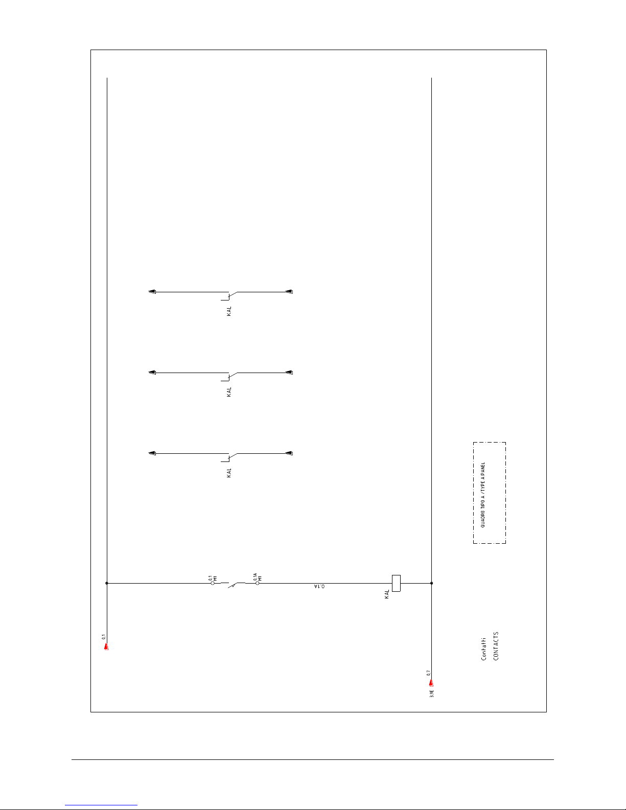
6.7 CONTACTS
0. 3
0. 4
0. 19
0. 3A
0. 4A
0. 19D
FC
 Loading...