

Page 1
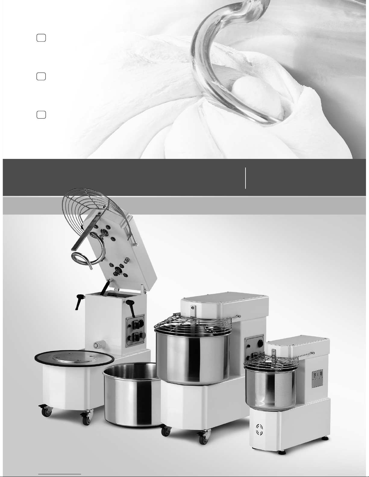
IMPASTATRICE A SPIRALE SERIE IM
MANUALE DUSO E MANUTENZIONE
SPIRAL MIXER
MODEL IM
Operating manual
GB
SPIRALTEIGKNETMASCHINE
MODELL IM
Bedienungsanleitung
D
PÉTRIN À SPIRALE
MODÈLE IM
Manuel dutilisation
F
Page 2

SUMMARY
CHAPTER 1 GENERAL INFORMATION................................................................................ 24
CHAPTER 2 INSTALLATION................................................................................................. 31
CHAPTER 3 FUNCTIONING.................................................................................................. 33
CHAPTER 4 USAGE ............................................................................................................. 36
CHAPTER 5 MAINTENANCE ............................................................................................... 39
CHAPTER 6 DEMOLITION OF THE MACHINE...................................................................... 41
CHAPTER 7 AFTER SALE SERVICE ...................................................................................... 42
23
ENGLISH
Prefix
This manual is specifically for the installation, use and maintenance of spiral mixers. So you are able to use the product
in the best way. It is important that the manual is kept in good condition and should stay with the machine at alltimes,
including sale to another person, for security in the use of the machine.
The manufacturer is not under any obligation to notify of any further modification of the product.
All rights of this document are reserved and no alternation or reproductions can be made without permission of the
manufacturer.
The following symbols are incluted to better stress some passages:
WARNING:
indicates hazards that may cause serious damages; attention is required.
INFORMATION:
indicates particularly important technical information.
Page 3

24
SPIRAL MIXER - IM SERIES Operating manual
CHAPTER 1 GENERAL INFORMATION
1.1 Warranty
Guaranteed for 2 years from date of purchase. The date must be stamped on the guarantee on
the date of purchase. Parts of the machine found to be a production defect exept electrical
components or parts worn out, will be changed and serviced free by us in our firm but only ex our
factory within this period. Delivery expences and costs of labour are excluded from the warranty.
The warranty will not be valid when the damage is due to: transportation, mistaken or insufficient
maintenance, unskilled operators, damaging, repairs made by unauthorized personnel, nonobservance of the instructions of the manual.
All reimbursements from the manufacturer are excluded for direct or indirect damages caused in
the time the machine is inactive for the following reasons: breakdown, waiting to be repaired, or
anyway the nonpresence of the machine.
1.2 Characteristics of the machine
The mixers in the models with fixed top and bowl or with raising top and removable bowl were
made with the intention for food usage only, to mix doughs made by cereal flours, for the prevalent
use in: pizza-restaurant, bread and bakery shops.
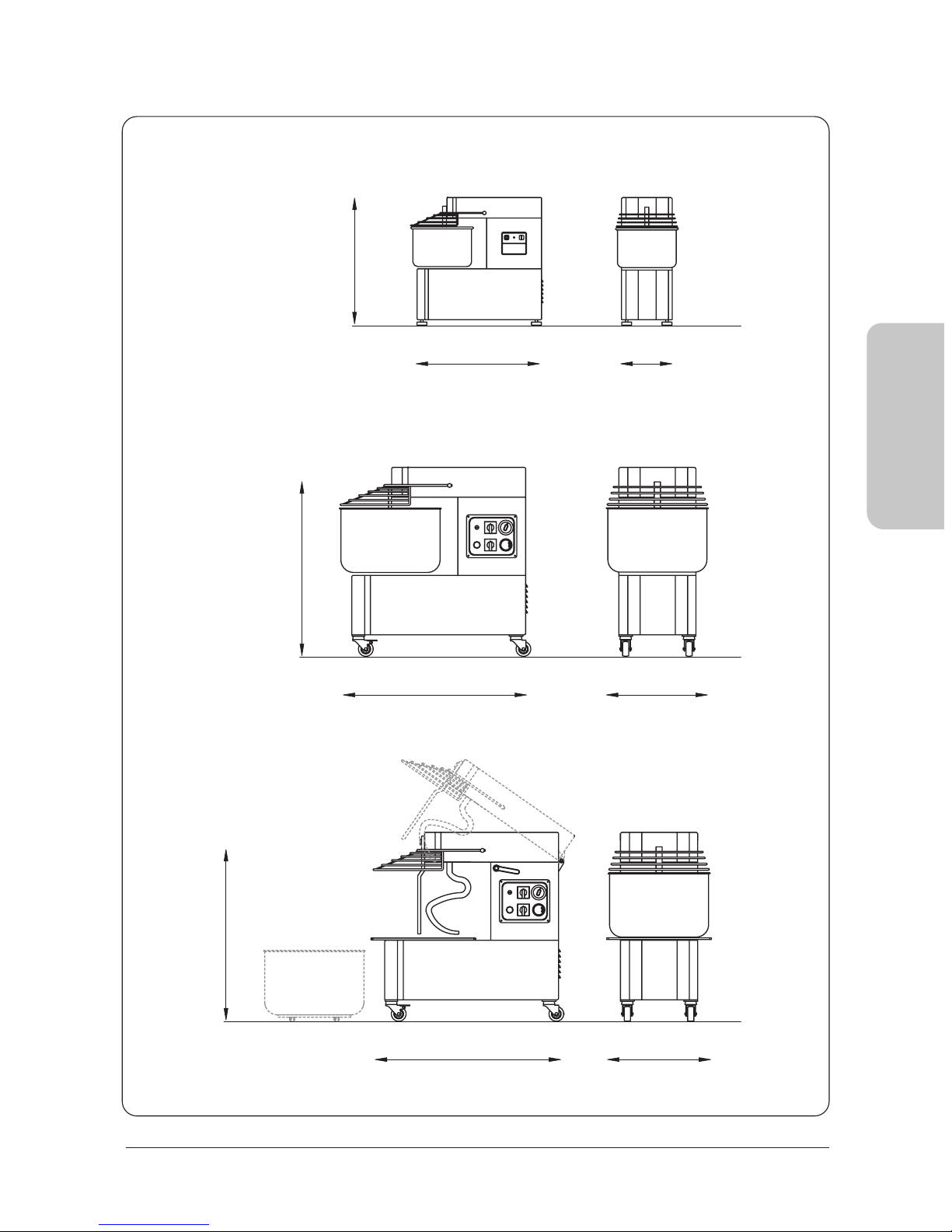
Every mixer (PICT. 1) is composed of:
· A steel structure protected by a heat resistant varnish.
· The bowl, the spiral, the central doughbreaker and the protection grate are all in stainless steel.
· Chain drive with oilbath gearmotor.
· The moving parts are on ball bearing.
· Type feet (from models IM 5 and IM 8), set of wheels (for models from IM 12 to IM 44), type feet
in stainless steel and wheels in nylon (for IM 60)
· Operation with single-phase or threephase motor, one speed; on request: threephase motor with
two speeds and timer (apart from models IM 5 and IM 8).
· Electric circuit fed by a cable to the network to which are connected at low tension (24V) the
control devices to start, to stop, and of the safety devices. Among these l'internal blocking of the
moving parts activated by the movement of the mobile protection of the pan.
ENGLISH
Page 4
25
ENGLISH
PICT. 1
IM 5; IM 8
B
AC
IM 12; IM 18; IM 25; IM 38; IM 44
B
AC
IM 12A; IM 18A; IM 25A;
IM 38A; IM 44A
AC
B
Page 5

26
SPIRAL MIXER - IM SERIES Operating manual
1.3 Technical characteristics
ENGLISH
LIFTABLE HEAD AND EXTRACTIBLE STEEL BOWL
Kg Kg Lt Kw A C B Kg
FIXED HEAD AND FIXED STEEL BOWL
mm
IM 5M
IM 5T
IM 8M
IM 8T
IM 12M
IM 12T
IM 12D
IM 18M
IM 18T
IM 18D
IM 25M
IM 25T
IM 25D
IM 38M
IM 38T
IM 38D
IM 44M
IM 44T
IM 44D
IM 60M
IM 60T
IM 60D
IM 12AM
IM 12AT
IM 12AD
IM 18AM
IM 18AT
IM 18AD
IM 25AM
IM 25AT
IM 25AD
IM 38AM
IM 38AT
IM 38AD
IM 44AM
IM 44AT
IM 44AD
5
5
8
8
12
12
12
18
18
18
25
25
25
38
38
38
44
44
44
60
60
60
12
12
12
18
18
18
25
25
25
38
38
38
44
44
44
3
3
5
5
8
8
8
12
12
12
17
17
17
25
25
25
30
30
30
40
40
40
8
8
8
12
12
12
17
17
17
25
25
25
30
30
30
7
7
10
10
15
15
15
20
20
20
33
33
33
40
40
40
50
50
50
75
75
75
15
15
15
20
20
20
33
33
33
40
40
40
50
50
50
0,37
0,37
0,37
0,37
0,9
0,75
0,6/0,8
0,9
0,75
0,6/0,8
1,1
1,1
1/1,4
1,5
1,5
1,5/2,2
1,5
1,5
1,5/2,2
2,6
2,6
2,6/3,4
0,9
0,75
0,6/0,8
0,9
0,75
0,6/0,8
1,1
1,1
1/1,4
1,5
1,5
1,5/2,2
1,5
1,5
1,5/2,2
230/50
400/50/3
230/50
400/50/3
230/50
400/50/3
400/50/3
230/50
400/50/3
400/50/3
230/50
400/50/3
400/50/3
230/50
400/50/3
400/50/3
230/50
400/50/3
400/50/3
230/50
400/50/3
400/50/3
230/50
400/50/3
400/50/3
230/50
400/50/3
400/50/3
230/50
400/50/3
400/50/3
230/50
400/50/3
400/50/3
230/50
400/50/3
400/50/3
540 x 260 x 527
540 x 260 x 527
550 x 280 x 555
550 x 280 x 555
675 x 350 x 690
675 x 350 x 690
675 x 350 x 690
697 x 390 x 690
697 x 390 x 690
697 x 390 x 690
762 x 430 x 770
762 x 430 x 770
762 x 430 x 770
818 x 480 x 770
818 x 480 x 770
818 x 480 x 770
842 x 530 x 770
842 x 530 x 770
842 x 530 x 770
1020 x 575 x 1010
1020 x 575 x 1010
1020 x 575 x 1010
690 x 350 x 690
690 x 350 x 690
690 x 350 x 690
715 x 390 x 690
715 x 390 x 690
715 x 390 x 690
780 x 430 x 770
780 x 430 x 770
780 x 430 x 770
838 x 480 x 770
838 x 480 x 770
838 x 480 x 770
878 x 530 x 770
878 x 530 x 770
878 x 530 x 770
33
33
36
36
60
60
60
65
65
65
95
95
95
105
105
105
110
110
110
250
250
250
80
80
80
85
85
85
115
115
115
130
130
130
140
140
140
237 x 160
237 x 160
260 x 200
260 x 200
317 x 210
317 x 210
317 x 210
360 x 210
360 x 210
360 x 210
400 x 260
400 x 260
400 x 260
452 x 260
452 x 260
452 x 260
500 x 270
500 x 270
500 x 270
550 x 370
550 x 370
550 x 370
317 x 210
317 x 210
317 x 210
360 x 210
360 x 210
360 x 210
400 x 260
400 x 260
400 x 260
452 x 260
452 x 260
452 x 260
500 x 270
500 x 270
500 x 270
M= Monophase Motor T= Threephase Motor D= Threephase Motor 2 speeds
Model Kneading capacity Flour capacity Bowl volume Motor power Volt Dimensions mm WeightBowl dimension
Page 6
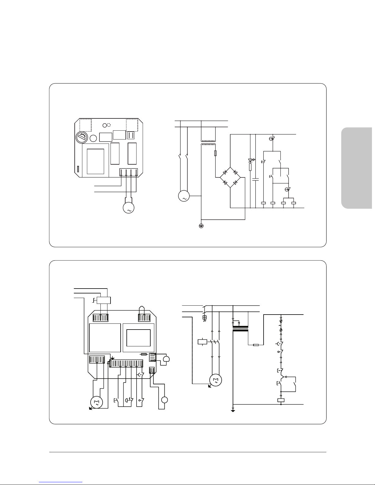
1.4 Electrical schemes
27
ENGLISH
SINGLE-PHASE CONNECTION IM 5-8 M
TM
N
L
F500mA
F
TM
2,5VA
START
RL1
1
M
RP1 RP2
+
-
B
Led
C
MC1
START
RL1 RP1 RP2
+
-
1
M
UV
L
1
L
2
LINE
GND
B
RL2
STOP
C
LED
RP1
RP2
F500mA
RL2
STOP
R2
MC2
SINGLE-PHASE CONNECTION IM 12-18-25-38-44 M
L
N
Q15
L2 L3
LINE
123
T16K18M
11-
PE
F500mA
M15
1
MC
T
14 9PT8 7 10 11
F17
START-
12
13
PE
N
L
Q15
1
M15
K18M
L
N
1
3 2
230V
F500mA
F17
T16
8VA
24V
(14)
(13)
PT
(12)
(11)
T
MC
(10)
(7)
STOP
START
(8)
13
14
K18M
(9)
A1
A2
K18M
Page 7
28
SPIRAL MIXER - IM SERIES Operating manual
ENGLISH
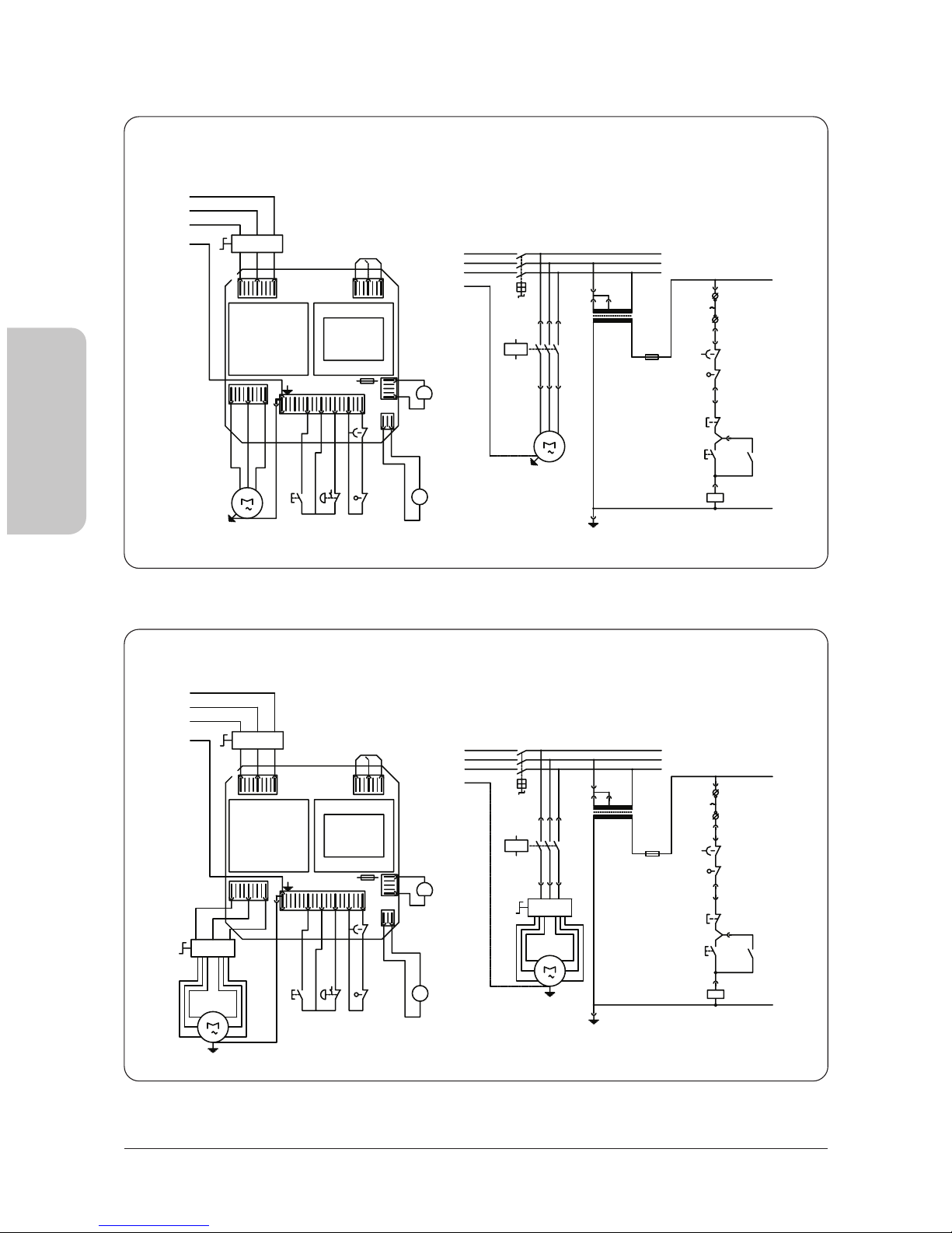
THREE-PHASE CONNECTION IM 12-18-25-38-44-60 T
PE
L1
A2
K18M
A1
(9)
K18M
14
13
(13)
(11)
(12)
(10)
(7)
(8)
START
STOP
MC
T
PT
(14)
F500mA
F17
MC
24V
8VA
T16
230V/400V
23
1
K18M
L1
PE
Q15
M15
3
K18M T16
13
12
START-
F17
111078PT914
T
3
M15
F500mA
1-
1-
321
LINE
L3L2
Q15
L2
L3
L1
L2
L3 L3
L2
L1
THREE-PHASE CONNECTION 2 VEL. IM 12-18-25-38-44-60 D
230V/40
L1
L2
L3L3
L2
L1
3
L1
L1
L2
L3
PE
LINE
Q15
L2 L3
123
11-
F500mA
M15
T
14 9PT8 7 10 11
F17
START-
12
13
T16K18M
Q15
PE
K18M
1
32
T16
8VA
24V
MC
F17
F500mA
(14)
PT
T
MC
STOP
START
(8)
(7)
(10)
(12)
(11)
(13)
13
14
K18M
(9)
A1
K18M
A2
COMM
M15
3
COMM
Page 8
29
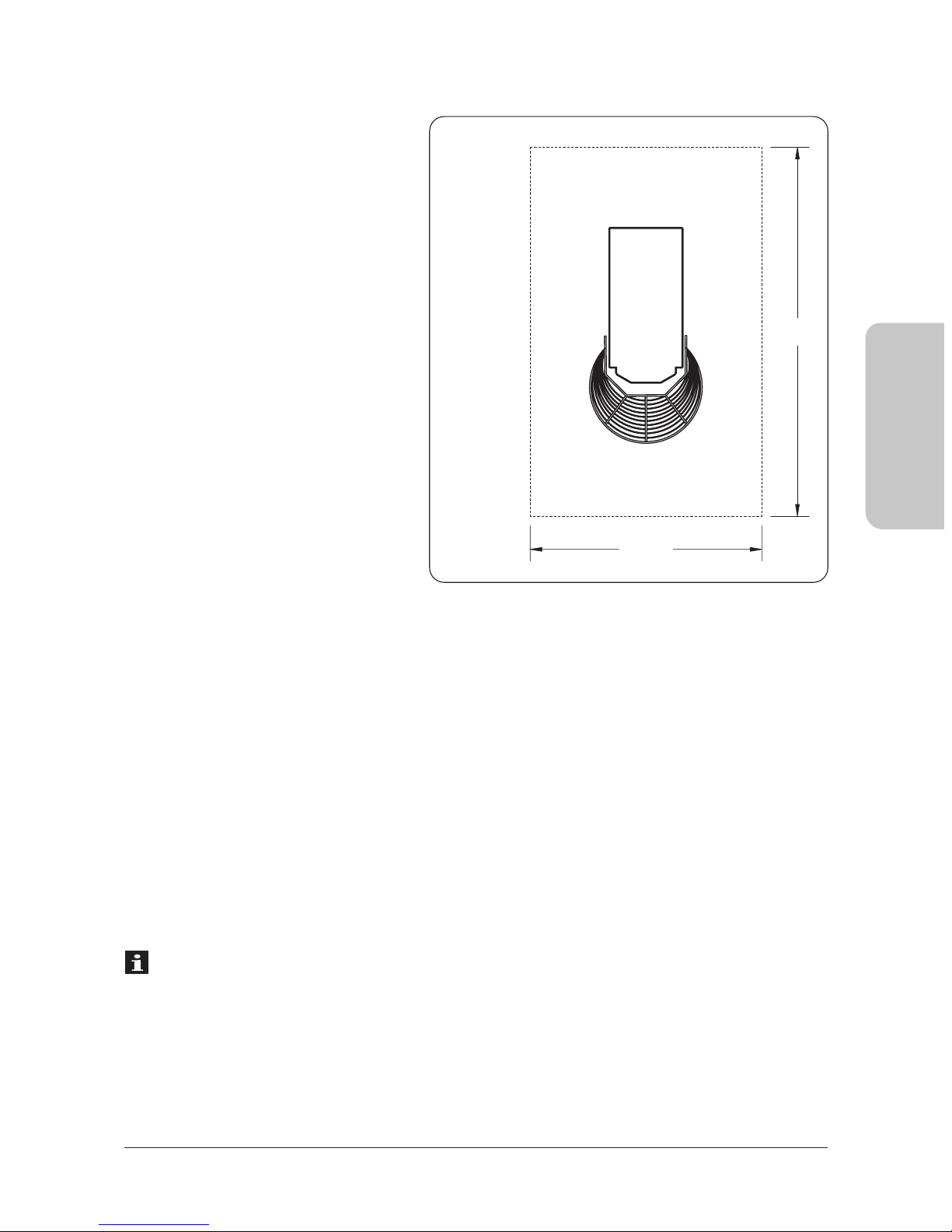
1.5 Operating area
In normal working conditions and to have the best exploration of the potentiality of the machine,
the operator needs the area represented in PICT. 2.
1.6 Security indications
Although the machine is built in conformity to the required security rules regarding electrical,
mechanical and hygienic regulation it can be dangerous if:
· Used in case and condition different to those described by the manufacturer.
· Manomission of the protection and of the safety devices.
· Innattention to the instruction of: Installation - Functioning - Usage - Maintenence.
INFORMATIONS
Installation and maintenence have to be done by qualified personnel authorized by the
manufacturer who is not responsable for any mistaken installation or manomission.
ENGLISH
Electrical schemes
SINGLE-PHASE
AND THREE-PHASE CONNECTION
IG = General switch
T16 = Transformer
F17 = Fuse
PT = Thermoproction of the engine
FC = Safety photocell
MC = Safety limit switch
STOP = Stop button
START = Operating button
K18M = Contactor
LI = Operating light
M = Engine
PICT. 2
mt 1,5
mt 2
Page 9

30
SPIRAL MIXER - IM SERIES Operating manual
ENGLISH
1.7 Security indications
INFORMATION
Carefully read the instruction before using the machine.
WARNING
The avoid dangerous condition and/or possible injuries caused from: electric current, mechanical
parts, fire or hygienical problems, you must follow the security indications step by step.
A) Keep in order your working area. Disorder can cause dangerous accidents.
B) Consider environmental conditions. Do not use the machine in humid, wet or nadly
lit environments, close to inflamable liquids or gas.
C) Keep away from children and non authorized personnel. Do not permit them to go
near the machine or the working area.
D) Only utilize the machine with the correct voltage. Normal usage gives better results.
E) Dress in adequate way. Do not wear hanging clothes or any items which can be caught
in the machine. Use non-slip shoes. For hygiene and safety keep your hair tied back and
wear protective gloves.
F) Protect the cable. Do not pull the cable to extract the plug. Do not leave the cable
near high temperatures, sharp objects, water or solvents.
G) Avoid insecure positions. Find the best surface to ensure the machine is balanced.
F) Always pay maximum attention. Do not be distracted when using the machine.
I) Take the plug out. When the machine is not in use, before cleaning, maintenance
and moving it.
L) Do not use further extensions.
M) Check that the machine is not damaged. Before using the machine carefully check
that all security devices are working. Check that: the mobile parts are not blocked,
there are not any parts damaged, all the parts have been set up correctly and all the
conditions that could influence the regular functioning of the machine
are in working order.
N) Repairing the machine by qualified personnel. The repairs can only be done by qualified
people, using original spare parts. The non- compliance with these rules can represent
danger for the user.
Page 10

31
2.1 Instructions for the user
The environmental conditions in which the machine must be installed must follow these characteristics:
· Be dry
· The machine is constructed to have IPXI protection level.
· Water and heat sources at safe distance
· Adequate ventilation and lighting corresponding to hygiene and security regulations following
the existing laws.The surface should be flat and compact for easier cleaning. For normal ventilation
of the machine no objects should obstruct.
INFORMATION
The electric network must be provided with an automatic differential switch having characte
ristics suitable to those of the machine, in which the opening distance between the contacts
must be of at least 3 mm. Most of all it is necessary a good grould system.
WARNING
Verify that the electrical set-up corresponds with the numbers of the technical characteristics
(1.3) found and on the small plate at the back of the machine.
2.2 Installation methods
The machine is supplied in a closed package and fixed with metal straps on wood. Inside the
packaging with the machine you will find the instructions and the declaration of conformity
according to the machines regulation. The machine must be unloaded and lifted out at the part
indicated on the packaging by proper equipment. For the transportation of the machine to the
place of installation, use a fork lift.
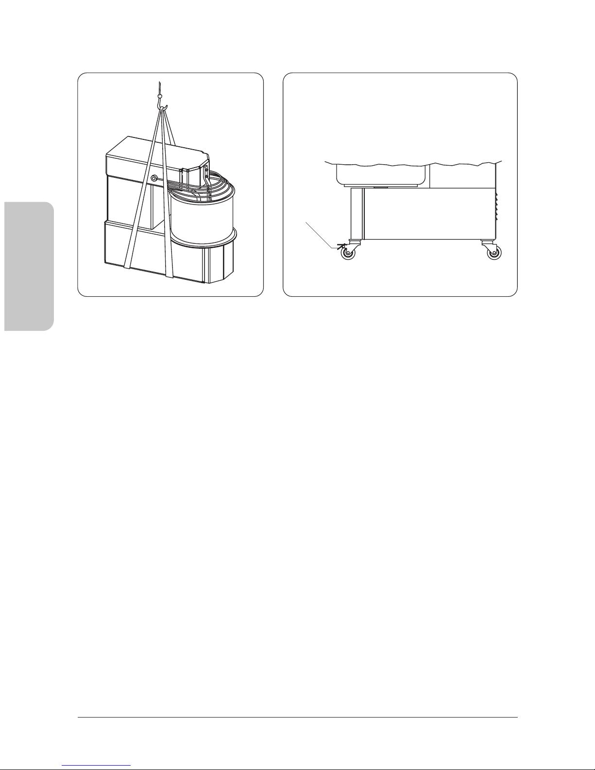
After cutting the metal straps take out of the packaging and the plastic cover, then with the help
of a proper belt put under the machine (PICT. 3) and a fork lift (manual or motor) lift the machine
and take away the bottom pallet, position the machine making sure you leave a space around it
of 50 cm to make usage, cleaning and maintenance easier. If the machine is unstable put under
the feet or wheels pieces of hard rubber. If the machine has wheels make sure they have been
blocked by pushing the lever A downwards till it blocks (PICT. 4).
Note: All packaging must be disposed of in a lawful way.
CHAPTER 2 INSTALLATION
ENGLISH
Page 11
32
SPIRAL MIXER - IM SERIES Operating manual
2.3 Electrical connections
The connections type Y of the machine with the electric network is made by means of an operation
cable, which is provided with a plug only in the singlephase model. As far as the three-phase
machines are concerned it is necessary to put together the cable and a normalized and polarized
plug (the distinction between phase and neutral must be unequivocal), and verify that the rotation
way of the bowl is the same indicated by the arrow on the bowl.
2.4 Positioning of the machine
The plug must be easily accessible, must not require any kind of movement. The cable from the
machine to the wall plug must not be pulled tightly, also do not rest the machine on the cable.
ENGLISH
A
PICT. 3 PICT. 4
Page 12
33
ENGLISH
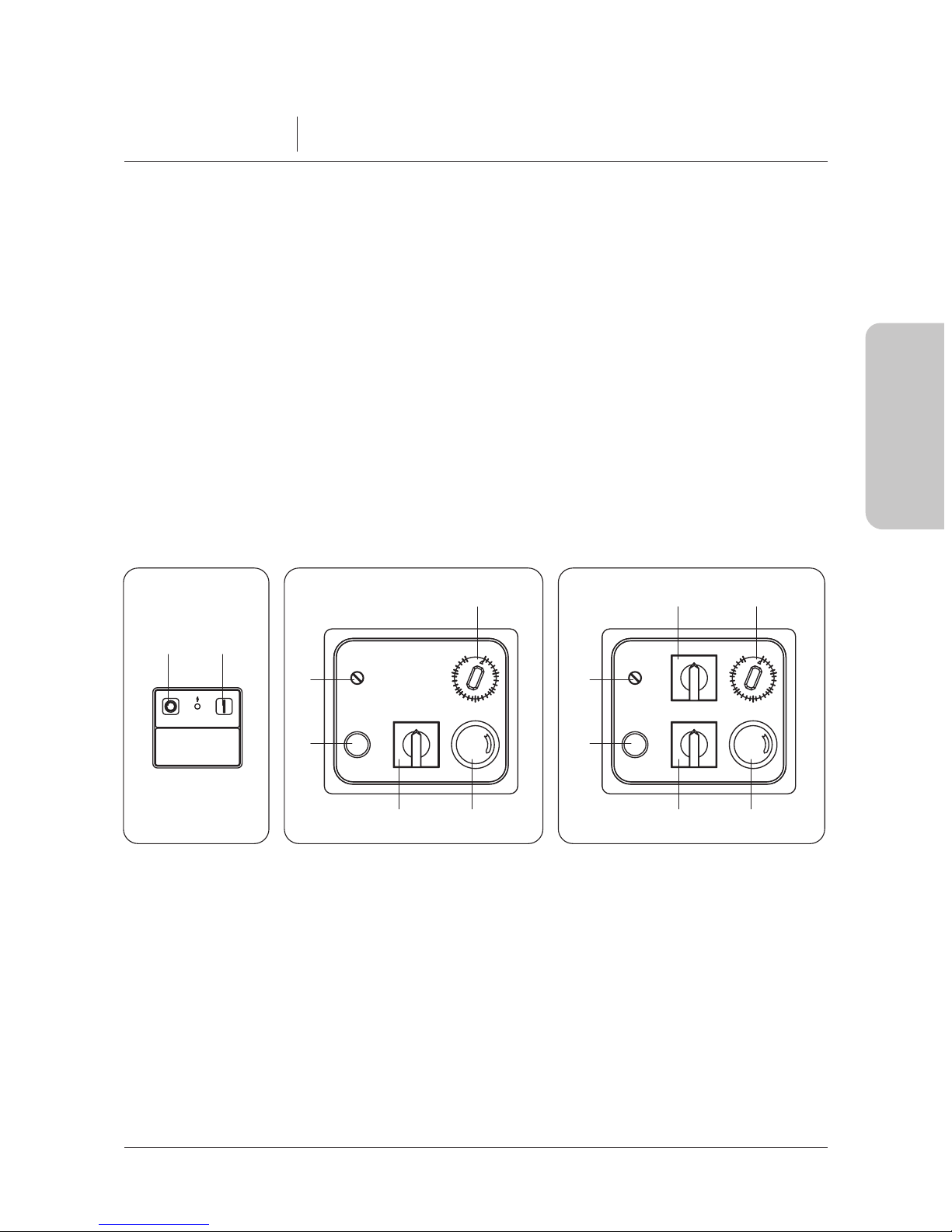
The machines are provided with the following operating and safety devices:
3.1 Operating devices
Single-phase or Threephase machines (IM 5 - IM 8) (PICT. 5):
A - Green button 1 operating
B - Red button 2 Stop
Single-phase or Three-phase machines (the rest of the models) (PICT. 6-7):
C - General switch
D - Green button: Operating
E - Red button: Emergency stop
F - Timer
G - Fuse
H - Speed commutator
CHAPTER 3 FUNCTIONING
3.2 Safety devices
I - Moving protection grate (PICT. 8)
L - Device proving that the top and the protection cover are up or down
M,M1- Check pin of the top (down position)
N - Device proving that the bowl is in or out
O -Blocking disk of the bowl
Note:
The safety devices M,M1-N-O can be found only in the machines wih raising top and
removable bowl (A models). The device proving that the protection cover is up or down is located
inside the head of the machine on the models with fixed top.
1
0
2
0
1
RETESTOP START
BA
PICT. 5 PICT. 6 PICT. 7
0
5
10
15
20
25
30
1
0
0
5
10
15
20
25
30
F
G
D
CE
F
G
D
H E
C
Page 13
34
SPIRAL MIXER - IM SERIES Operating manual
ENGLISH
WARNING
The single safety device are efficient when:
· On raising the protetion I (PICT. 8) the machine stops.
· On raising the top (by means of the check pin M and/or taking off bowl the machine does not start.
· On softly pulling either the bowl or the top they do not move.
Before operating the machine, the protection I (PICT. 9) must be completely lowered. In the A models
it must be checked that the bowl is correctly inserted and blocked by the disk O and that the top is
down and blocked by the check pin M (this must be completely inserted). After inserting the plug the
machine is ready for use.
PICT. 8
M
M1
I
O
PICT. 9
P
Page 14

35
ENGLISH
3.3 Working test machine
Single-phase or three-phase machine (mod. IM 5 - IM 8):
OPERATING: push the green button A to start the bowl and the spiral.
STOP: push the red button to stop the bowl and the spiral.
Single-phase or three-phase machine (1-2 vel.) (from mod. IM 12 to mod. IM 60)
OPERATING: rotate the knob of the switch C in position 1, set the time of mixing by the timer F,
push the green button D to start the bowl and the spiral.
STOP: rotate the knob of the switch C in position 0, or push the red button E to stop the bowl and
the spiral. In order to operate the machine again after the stop due to the raising of the protection
I or to the activating of the emergency button E it is necessary to proceed as follows: lower again
and completely the protection I; release the button E by rotating in clockwise, as shown by the
arrow, and push the operating button D.
Note:
In a machine fed electrically by three-phase, if the rotation of the bowl is opposite the way
shown by the arrow it is necessary to follow these indications for the functioning and every time you
change the electric plug:
· Stop the machine.
· Take the plug out.
· Reverse on the plug the position of two phases (example: L1 with L2 and vice versa).
· Restart the machine and verify if the bowl is rotating the right way.
Start the machine without using it, let it on for about one minute and verify that it is functioning perfectly.
Page 15

Before starting work make sure that the machine is perfectly clean in particular, the surfaces of
bowl, the spiral and of the central column that have contact with the food products. If necessary
clean them following indications at 5.1.
4.1 Usage of the machine with fixed top and bowl
After lifted up the protection I, pour in the bowl all the required ingredients, push down the
protection, press the button to start A or D. The movement made by the spiral, which is sincronized
with the rotation of the bowl, gives an amalgamation of, flour, water, salt, yeast and other eventual
ingredients till you obtain a mixture of the consistance required. If necessary, in order to modify
the characteristics and/or the consistence of the initial dough, pour the ingredients through the
protection grate I. When work cycle is completed, leave machine on hold, lift up the mobile
protection to maximum opening, take mixture out of the bowl, proceed with cleaning of the machine
following the indications at 5.1.
4.2 Usage of the machine with raising top and removable bowl
The machine with raising top and removable bowl, is functionally identical to the machine with
fixed top and bowl.
It differentiates from the other only for the following advatages, that it can offer at the end of
each work cycle:
· The facility in the collection of the dough.
· The facility in the cleaning phase.
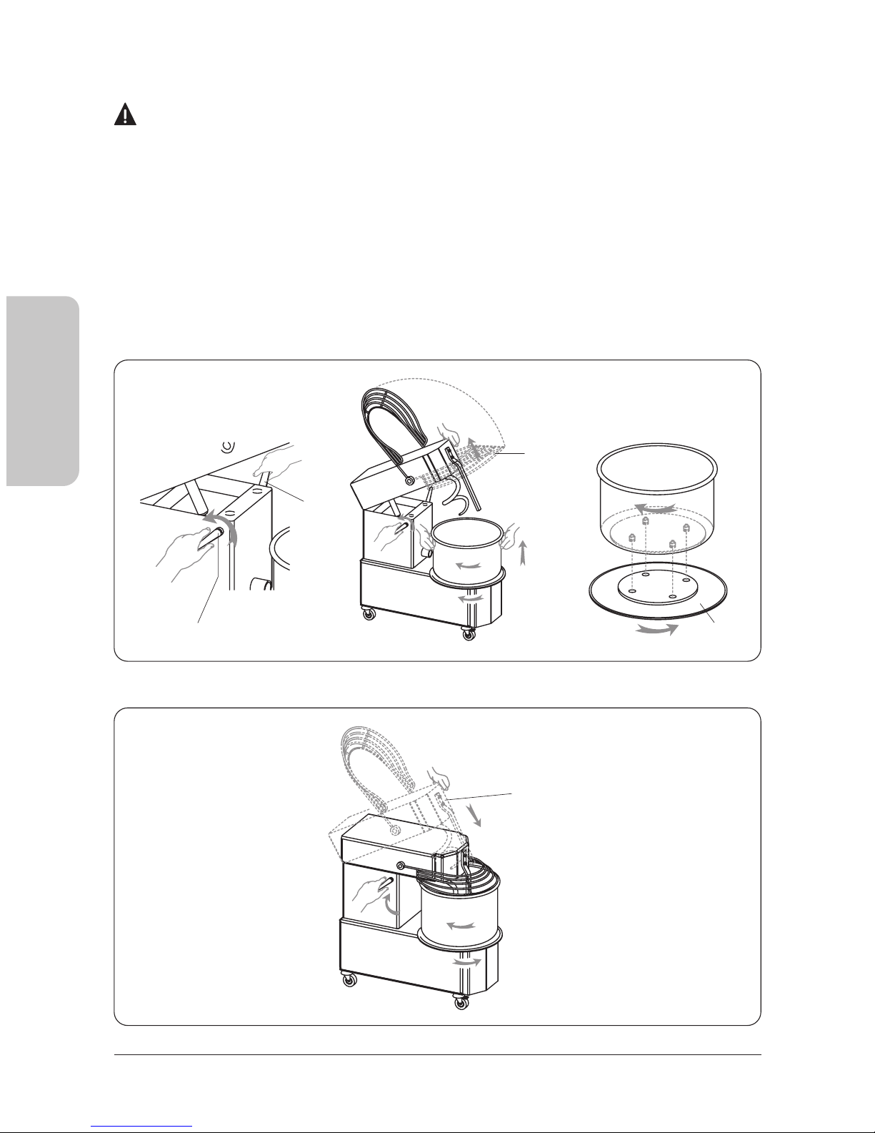
4.2.1 Raising of the top and taking off of the bowl
In order to raise the top and to take off the bowl proceed ad follows: stop the machine, unplug
the machine, raise the protection I completely (PICT. 10), pull the pin M as far as the top is blocked,
raise the top by means of the little piston underneath, rotate clockwise the disk O as far as the
bowl is unlocked, raise the bowl and take it off, take off the dough.
CHAPTER 4 USAGE
36
SPIRAL MIXER - IM SERIES Operating manual
ENGLISH
Page 16
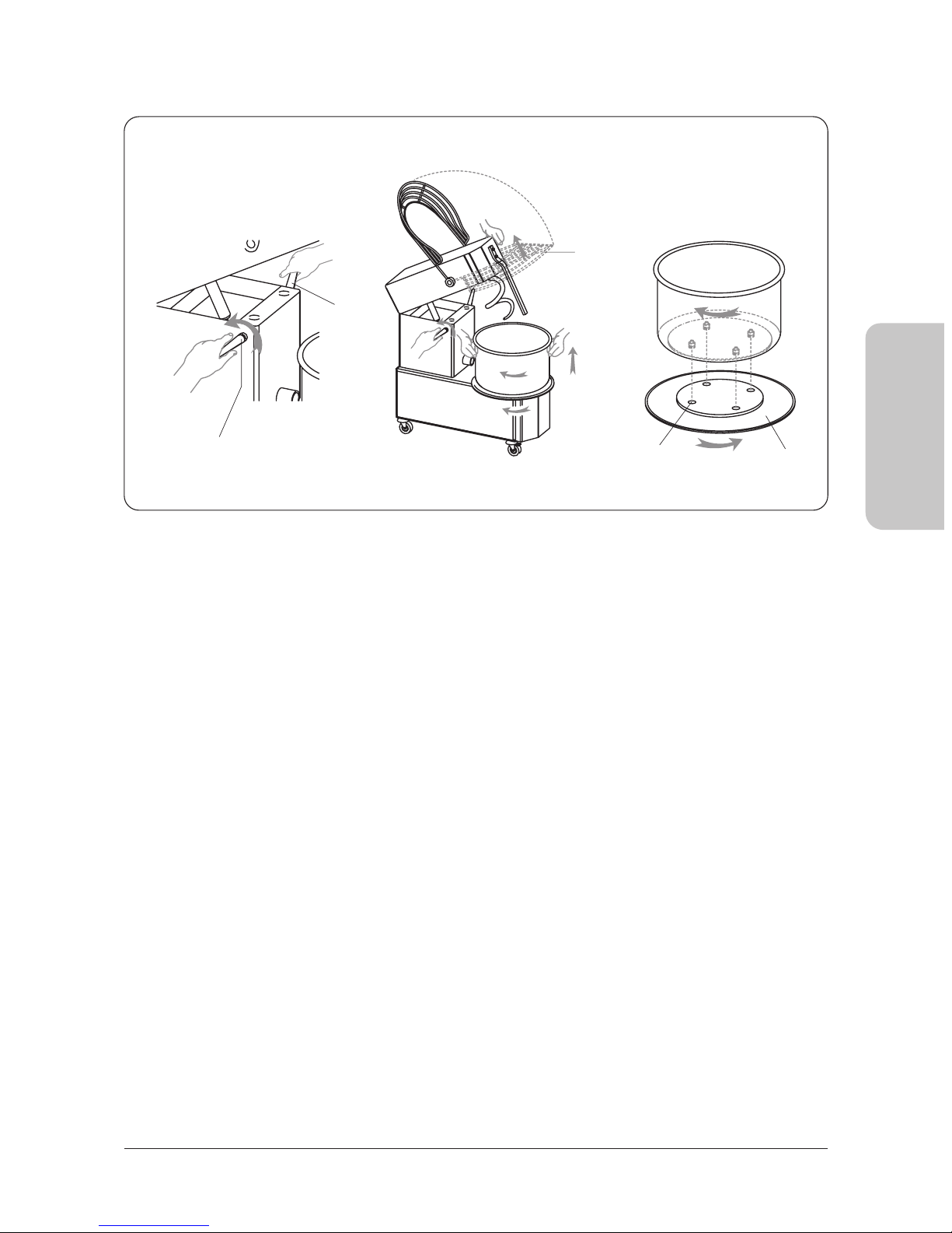
4.2.2 Repositioning of the bowl and top
Once the cleaning is done, put the bowl back on, and make sure that the four pins underneath
(PICT. 11) are correctly fixed in the four holes K of the machine; then block the bowl rotating
clockwise the disk O. Put the top down pushing it downwards (PICT. 9) as far as it is blocked by
the pin M.
4.3 Usage of the machine with two speeds
OPERATING: Rotate the knob of the switch C in position 1 (PICT. 7), select speed 1 or 2 by rotating
the knob of the selector H, push the green button D to operate both the bowl and the spiral. In
order to change the speed of rotation of the machine, rotate te knob H from position 1 to 2 or vice
versa. After each change of speed push the button D.
STOP: Rotate the knob of the switch C in position 0, or push the red button E to stop both the bowl
and the spiral.
PICT. 10-11
37
ENGLISH
M1
I
O
K
Page 17

4.4 Usage of the machine provided with timer
The timer is an electromechanical device that allows to program from 1 to 30 minutes.
· The work-time of the machine by rotating the knob 0 in the desired position (PICT. 13).
· Operate the machine following the instructions of par. 3.1 or 3.2 or 4.3.
· Once the set time is over, the timer stops the machine.
INFORMATION
Before taking off the dough beware of following the stop procedure of par 3.1 or 3.2.
38
SPIRAL MIXER - IM SERIES Operating manual
ENGLISH
Page 18

39
ENGLISH
WARNING
Before effecting any kind of maintenance or cleaning you must take out the plug. In any case
of malfunctioning or damage of the machine you must apply for authorized assistance from the
manufacturer (see Chapter 7).
5.1 Cleaning
The cleaning must be done every time the machine has been used following all the rules to prevent
malfunctioning of the machine and for hygienic purposes. Using a wooden or plastic palate first
clean the residue of dough, then with a soft sponge and warm water accurately clean the pan, the
spiral the dough breaker and the mobile protection, dry with kitchen paper, then pass over the
parts just mentioned then all the machine with a smooth and cleaned cloth with a specific cleaning
product for food machines.
WARNING
We recommend not to use any kind of chemical product abrasive or corrosive. Absolutely avoid
using running water, different tools, rough or abrasive objects, metal wool, sponges etc. which
can damage the surfaces and be dangerous from an hygienic point of view. To maintain the
efficiency and security of the machine it is necessary to proceed with periodical maintenance
(every 6 months) of the following indications:
5.2 Tensioning of the upper chain
The chain must be tensioned if, by checking it, it becomes loose or if the rotation of the spiral is
not constant. Unscrew the panel P, (PICT. 14) loosen the screws Q, pull the support of the spiral
R as far as the tension of the chain is optimzed, lock the support R with the screws Q, put the
panel P on once more and fix it.
CHAPTER 5 MAINTENANCE
Page 19
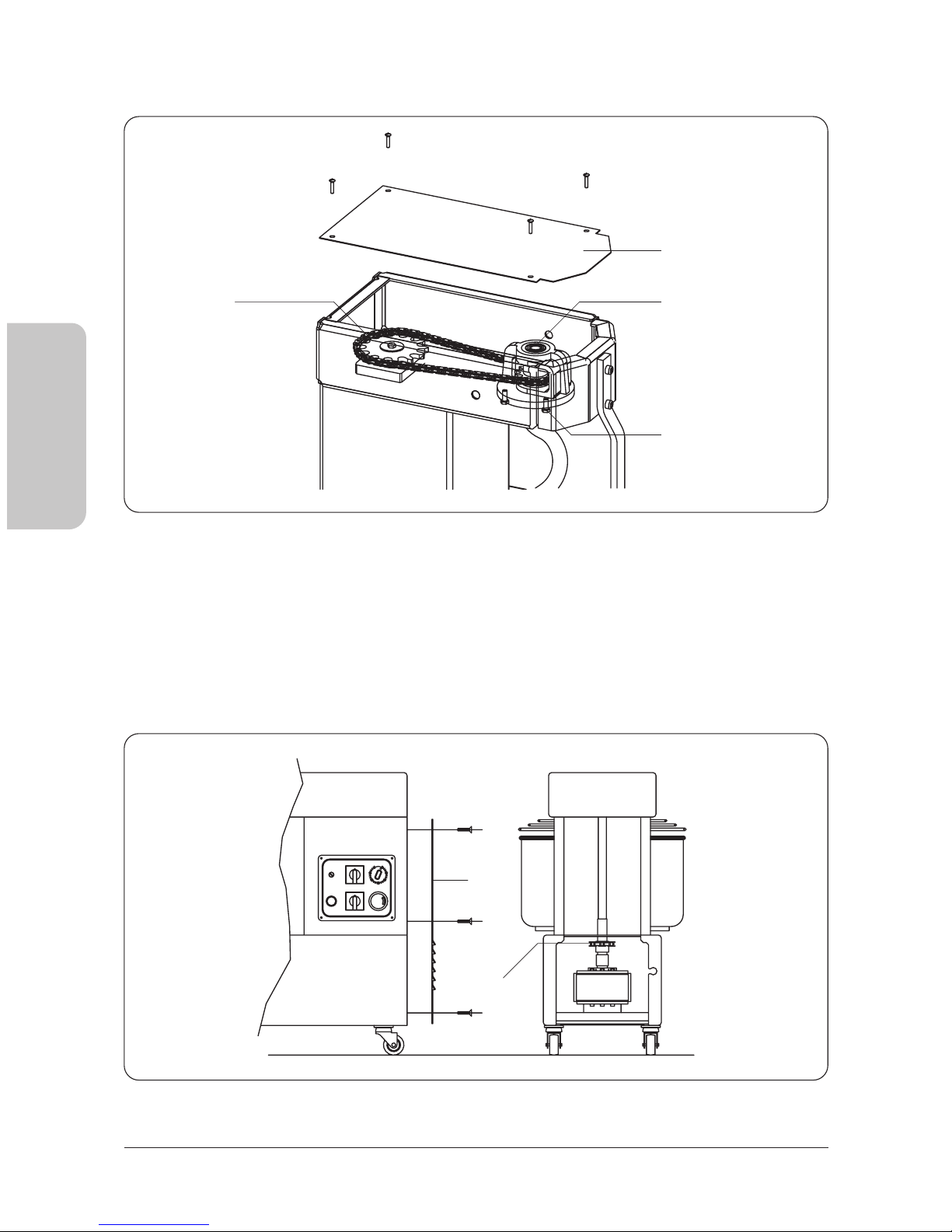
5.3 Lubrificating the chains
After unscrewing the fixing screws, take away the upper P and the back V panels, put on the
ichains S-T (PICT. 15-16) a reasonable amount of proper grease, sufficient to lubricate all the links
of the chain. Once this is done, mount the two panels and secure again with screws.
40
SPIRAL MIXER - IM SERIES Operating manual
ENGLISH
PICT. 16
V
T
PICT. 14-15
P
R
Q
S
Page 20

5.4 Possible anomalies
In case of dismantelling and demolition of the machine, the pieces which the machine is made
of, do not present any kind of danger that necessitates any particular caution.
To facilitate the recycling process of the materials, you must separate all electrical components.
CHAPTER 6 DEMOLITION OF THE MACHINE
41
ENGLISH
ANOMALY CAUSE SOLUTION
La macchina non si avvia
· Lack of energy in the
power grid
· The Emergency stop button
in blocked
· The protection grid
and/or the top are up
· The knob of the general switch
is in position 0
· The knob of the speed selector
is in position 0
· The timer is in position 0
· Check the general switch,
the plug, the tap and the
feeding cable
· Rotate the button following
the direction of the arrow
· Put down correctly both
the grid and the top
· Rotate the knob in position 1
· Rotate the knob in position
1 or 2
· Rotate the knob of the timer
from 1 to 30 minutes
The spiral turns incostantly
The machine stops while
working
· The chain is loose
· Stop of the fuse
· Stretch the chain following
the instructions at par. 5.2
· Change the fuse with another
on which has the same
characteristics
Page 21

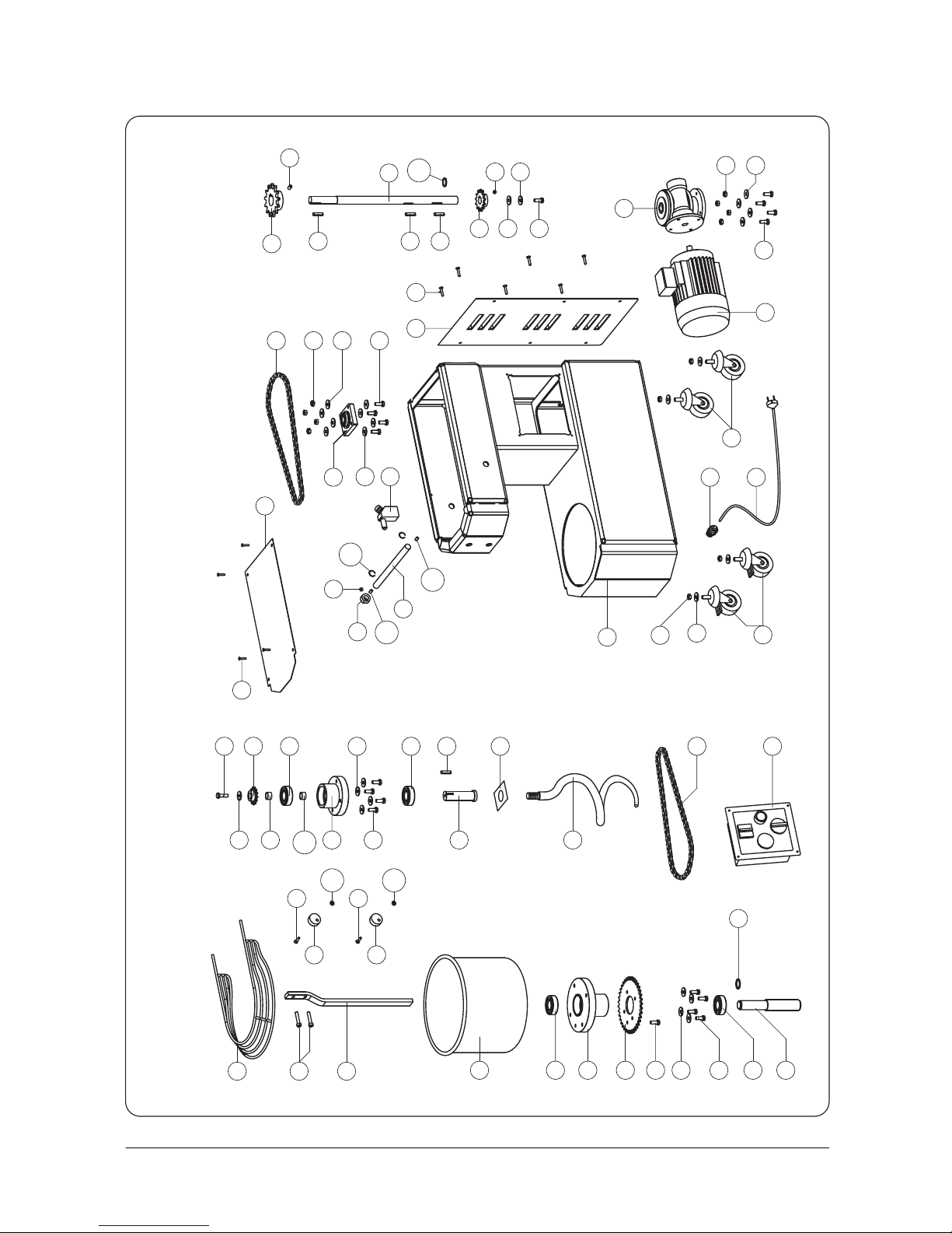
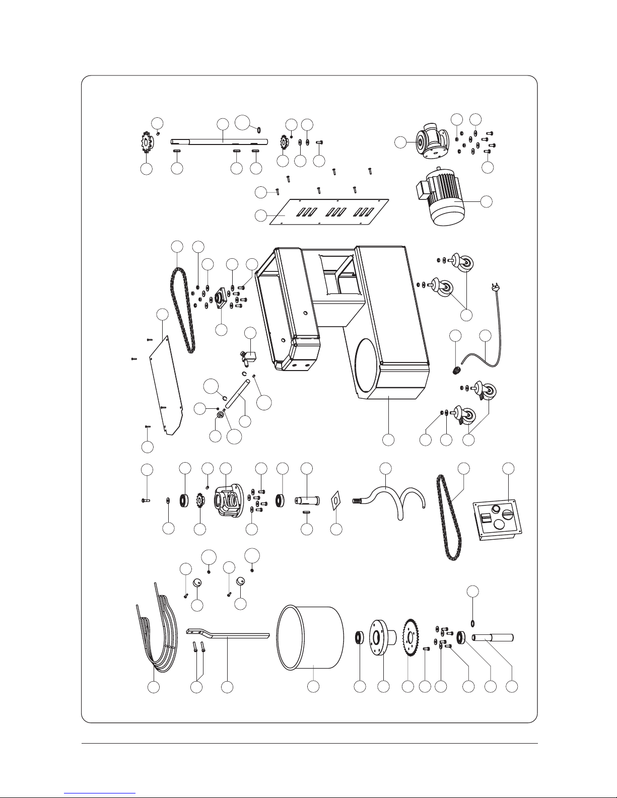
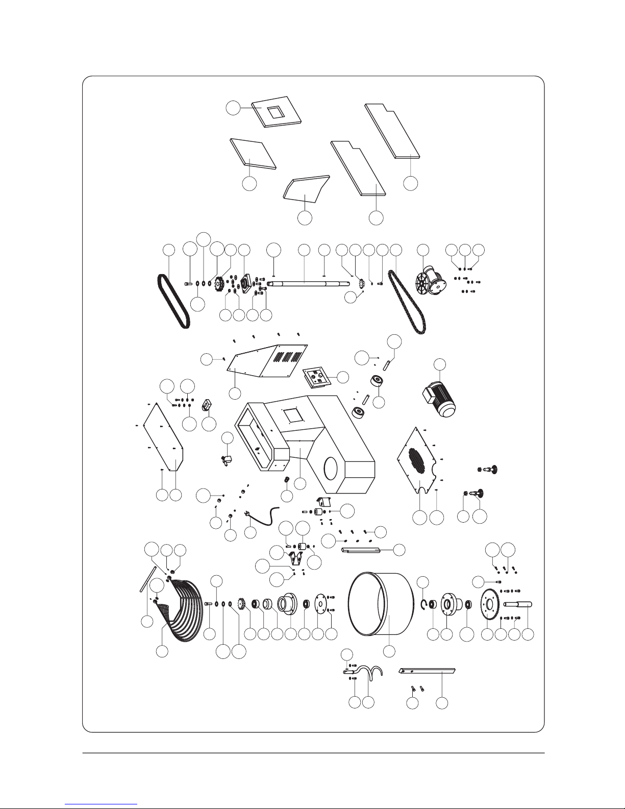
7.1 Spare parts
For a demand of spare parts, see the PICT. 17-22.
WARNING
We advise you to fit original spare parts only.
EEC countries:
Contact exclusively place of purchase.
CHAPTER 7 AFTER SALE SERVICE
42
SPIRAL MIXER - IM SERIES Operating manual
ENGLISH
Page 22
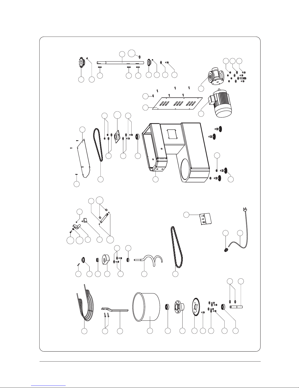
FIG. 17 Parti di ricambio impastatrice con testa e vasca fissa mod. IM 5-8
PICT. 17 Spare parts for mixer with fixed top and bowl mod. IM 5-8
83
FIG. 17 Pièces de rechange pour petrisseuse avec tete et cuve fixe mod. IM 5-8
BILD 17 Ersatzteile für die Teigknet-maschine mit gestem Kopl und Becken mod. IM 5-8
86
85
84
82
15
80
96
97
95
32
31
94
93
92
22
17
98
38
26
64
5
9
6
7
62
8
61
5
4
3
2
1
10
21
18
16
15
14
37
113
33
112
35
75
115
114
74
11
27
28
118
25
89
23
29
30
29
29
125
88
87
71
70
Page 23
9
5
7
64
62
61
8
6
5
4
72
2
73
123
3
73
123
72
1
69
11
21
20
10
19
18
16
67
124
66
15
17
15
14
36
28
13
12
86
32
97
83
82
80
85
93
94
25
27
35
98
24
26
22
23
95
96
31
99
92
89
75
74
34
117
88
87
91
30
29
29
116
117
125
71
70
FIG. 18 Parti di ricambio impastatrice con testa e vasca fissa mod. IM 12-18
PICT. 18 Spare parts for mixer with fixed top and bowl mod. IM 12-18
84
FIG. 18 Pièces de rechange pour petrisseuse avec tete et cuve fixe mod. IM 12-18
BILD 18 Ersatzteile für die Teigknet-maschine mit gestem Kopl und Becken mod. IM 12-18
Page 24
85
FIG. 19 Parti di ricambio impastatrice con testa e vasca fissa mod. IM 25-38-44
PICT. 19 Spare parts for mixer with fixed top and bowl mod. IM 25-38-44
FIG. 19 Pièces de rechange pour petrisseuse avec tete et cuve fixe mod. IM 25-38-44
BILD 19 Ersatzteile für die Teigknet-maschine mit gestem Kopl und Becken mod. IM 25-38-44
9
5
7
62
61
8
11
64
10
32
97
96
95
31
73
6
5
4
3
19
21
69
20
123
72
68
17
18
73
2
1
14
123
72
16
65
15
67
36
929499
93
88
87
28
89
25
22
23
86
12
83
85
13
82
80
35
24
27
98
26
75
74
34
117
116
117
71
70
91
30
29
29
125
Page 25
8
9
7
62
61
129
128
140
30
27
26
25
24
32
35
23
22
13
11
10
31
29
28
2
3
4
5
6
18
21
69
64
127
77
76
137
70
71
72
73
88
87
97
96
95
94
99
91
98
92
148
147
149
150
151
146
145
144
143
130
131
132
133
134
135
136
86
123
138
139
82
85
80
126
34
36
75
125
1
67
74
116
117
19
16
17
151466
68
142
141
154
155
153
152
156
86
FIG. 20 Parti di ricambio impastatrice con testa e vasca fissa mod. IM 60
PICT. 20 Spare parts for mixer with fixed top and bowl mod. IM 60
FIG. 20 Pièces de rechange pour petrisseuse avec tete et cuve fixe mod. IM 60
BILD 20 Ersatzteile für die Teigknet-maschine mit gestem Kopl und Becken mod. IM 60
Page 26

RIF.
1
2
3
4
5
6
7
8
9
10
11
12
13
14
15
16
17
18
19
20
21
22
23
24
25
26
27
28
29
30
31
DESCRIZIONE
PROT. VASCA
BULLONE ASTA ROMPIPASTA
ASTA ROMPIPASTA
VASCA
CUSCINETTO SUPPORTO VASCA
SUPPORTO VASCA
BULLONE CORONA VASCA
CORONA
ALBERO VASCA
CATENA VASCA
IMPIANTO ELETTRICO
RUOTA CON FRENO
RUOTA SENZA FRENO
PIGNONE SUPPORTO SPIRALE
CUSCINETTO SUPPORTO SPIRALE
SUPPORTO SPIRALE
RONDELLA
BULLONE
DISCO PROTEZIONE
ALBERO SUPPORTO SPIRALE
SPIRALE
CATENA SPIRALE
PIGNONE
SUPPORTO UCF ALBERO RIDUTTORE
DADO
RONDELLA
BULLONE
PIGNONE CATENA VASCA
CHIAVETTA
ALBERO RIDUTTORE
RIDUTTORE
RIF.
32
33
34
35
36
37
38
39
40
41
42
43
44
45
46
47
48
49
50
51
52
53
54
55
56
57
58
59
60
61
62
DESCRIZIONE
MOTORE
TRIANGOLO
AZIONATORE FINE CORSA
MICRO
BULLONE
CUSCINETTO
SUPPORTO TESTATA
RONDELLA SUPPORTO TESTATA
BULLONE SUPPORTO TESTATA
GIUNTO DI TRASMISSIONE
MOLLA A GAS
-
-
-
SENSORE DI PROSSIMITÀ VASCA
ALBERO TESTATA
PIEDE FISSAGGIO VASCA
DISCO FISSO
DISCO MOBILE
-
-
-
PROTEZIONE MICRO
SUPPORTO SENSORE VASCA
BULLONE FERMA CORONA
RONDELLA CORONA VASCA
89
Page 27

RIF.
63
64
65
66
67
68
69
70
71
72
73
74
75
76
77
78
79
80
81
82
83
84
85
86
87
88
89
90
91
92
93
DESCRIZIONE
FERMO BATTUTA DISCO MOBILE
SEGER ALBERO VASCA
GRANO PIGNONE SPIRALE
DISTANZIALE SUPPORTO SPIRALE
RONDELLA
CUSCINETTO SUPPORTO SPIRALE
CHIAVETTA ALBERO SPIRALE
VITE AUTOFORANTE CARTER TESTATA
CARTER TESTATA
VITE PER FERMO GRIGLIA
FERMO GRIGLIA
GRANO AZIONATORE FINE CORSA/TRIAN.
ALBERO GRIGLIA
PROTEZIONE VASCA
GRANO SUPP. SENS. VASCA
TELAIO
VITE REGOLAZIONE SENSORE VASCA
DADO RUOTA/PIEDE
RONDELLA NYLON RUOTA
PIEDE REGOLABILE
PRESSACAVO PER CAVO ALIMENTAZIONE
CAVO ALIMENTAZIONE
CARTER POSTERIORE
VITE AUTOFORANTE CARTER POST.
GRANO
SPINA ACCIAIO ALBERO TESTATA
CHIAVETTA
GRANO PIGNONE CATENA VASCA
RONDELLA FISS. ALBERO RIDUTT.
RIF.
94
95
96
97
98
99
100
101
102
103
104
105
106
107
108
109
110
111
112
113
114
115
116
117
118
119
120
121
122
123
124
DESCRIZIONE
BULLONE FISSAGGIO ALBERO RIDUTT.
DADO FISSAGGIO RIDUTTORE
RONDELLA FISSAGGIO RIDUTTORE
BULLONE FISSAGGIO RIDUTTORE
RONDELLA
RONDELLA FISS. ALBERO RIDUTT. 10 X 40
RUOTA
VOLANTINO
RONDELLA
BULLONE MOLLA A GAS
DADO AUTOBLOCCANTE MOLLA A GAS
COPPIGLIA ASTA AZIONAMENTO MICRO
GRANO GIUNTO DI TRASMISSIONE
CHIAVETTA
SEGER ALBERO TESTATA
PIEDE SERR. VASCA
PERNO CERR. TESTATA
MANIGLIA SERR. TESTATA
DADO
SEEGER
GRANO
SEEGER
GOMMA DISCO MOBILE
DADO PER FERMO GRIGLIA
DISTANZIALE CUSCINETTO SUPP. SPIRALE
90
Page 28

RIF. DESCRIZIONE
RONDELLA
RONDELLA
CUSCINETTO SUPPORTO VASCA
DADO
BULLONE
BULLONE
RONDELLA
SUPPORTO RULLO
MOZZO RULLO
RULLO
CUSCINETTO
SEGER
RONDELLA
PROTEZIONE INFERIORE
VITE AUTOFORANTE PROTEZIONE INFERIORE
PIEDE ANTERIORE
RIF.
141
142
143
144
145
146
147
148
149
150
151
152
153
154
155
156
DESCRIZIONE
MOZZO RUOTA
GRANO
TENDICATENA
DADO
RONDELLA
BULLONE
BULLONE
RONDELLA
RONDELLA
RONDELLA
CHIAVETTA
FONOASSORBENTE TRONCO SX
FONOASSORBENTE TRONCO CENTRALE
FONOASSORBENTE CASSONE SX
FONOASSORBENTE CASSONE DX
FONOASSORBENTE TRONCO DX
91
125
126
127
128
129
130
131
132
133
134
135
136
137
138
139
140
Page 29

IMPASTATRICE A SPIRALE
SERIE IM
Manuale duso e manutenzione
04/2007
I
SPIRAL MIXER
MODEL IM
Operating manual
04/2007
PÉTRIN À SPIRALE
MODÈLE IM
Manuel dutilisation
04/2007
SPIRALTEIGKNETMASCHINE
MODELL IM
Bedienungsanleitung
04/2007
GB
F
D
 Loading...