

Page 1
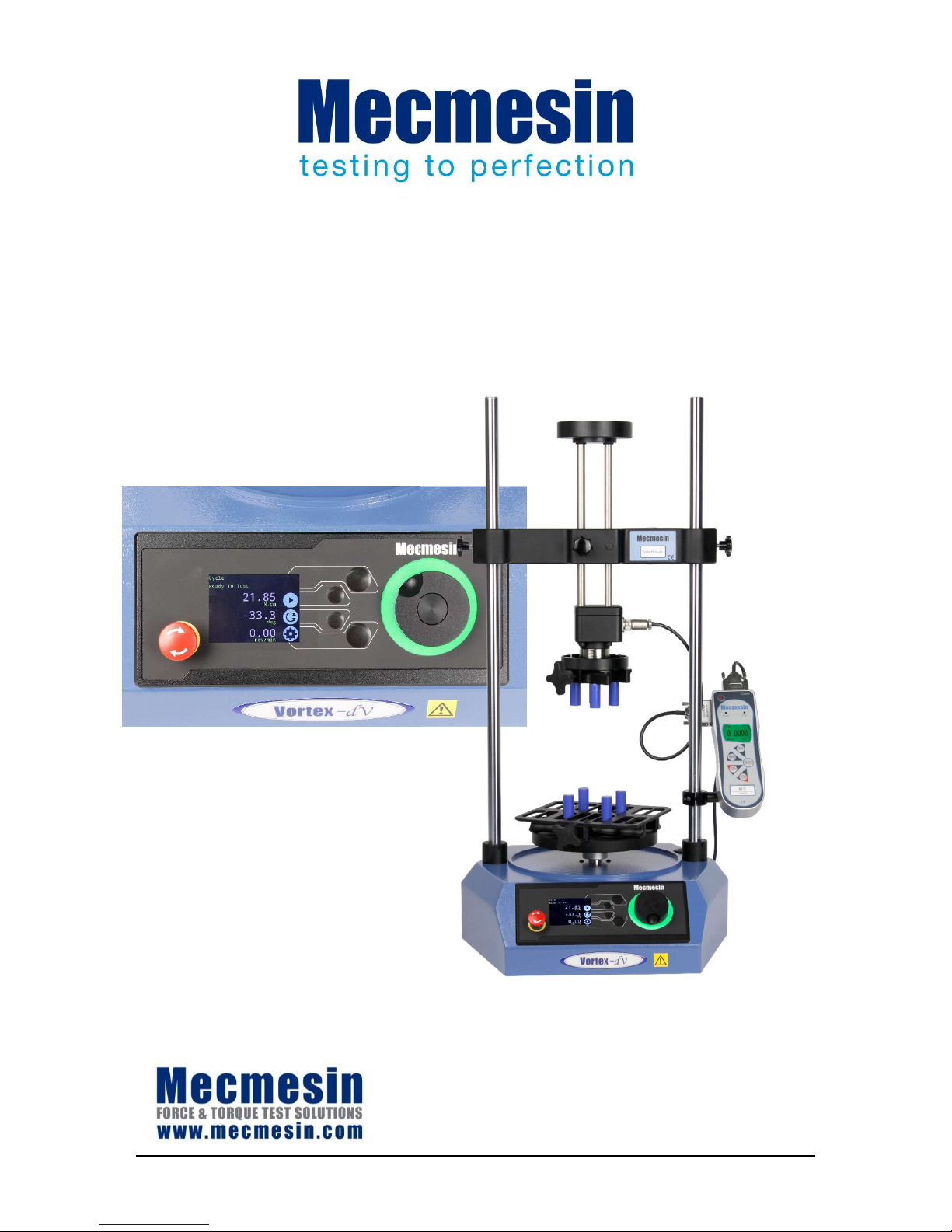
Vortex-dV Motorised Torque Testing
System Operating Manual
431
-
468
-04
February 2019
Page 2

Vortex-dV Operating Manual Mecmesin 2
The Scope of This Document
This document refers to Mecmesin Vortex-dV test stands with firmware version 3.0.10
It is essential that you familiarise yourself with the contents of this Manual and the
separate Guide to Safe Use of Mains Powered Test Systems before attempting to operate
your Vortex-dV Test System.
You may also need to refer to these documents:
431-955 VectorPro™ for Mecmesin Test Stands and Instruments
431-213 Advanced Force Gauge (AFG Mk4) Operating Manual
431-398 Guide to Safe Use of Mains Powered Test Systems
Important
This reference manual covers the operation of Vortex-dV test stands in conjunction with
the use of Mecmesin digital Advanced Force Torque Indicator (AFTI). Operation of the
AFTI is covered in a separate manual.
For operating in conjunction with Vector Pro™, see the manual 431-955, VectorPro™ for
Mecmesin Test Stands and Instruments.
2018 © Mecmesin Ltd, supplied with Mecmesin test systems and not for redistribution
Part no. 431-468-04
Page 3
3 Mecmesin Vortex-dV Operating Manual
Contents
1. Items Supplied With Your Test Stand 5
Available Accessories 5
2. Vortex-dV System Diagram 6
3. Initial Setup 7
Unpacking the Test Stand 7
Lifting the Test Stand 7
Environment Conditions 7
Locating the Stand 7
Mains Power Supply 8
Fuse Specification 8
Attaching the Torque Sensor 9
Fitting the AFTI Torque Indicator 10
Connecting the AFTI and the Vortex-dV 11
AFTI Communication Settings 11
Connect the Test Stand to a PC (VectorPro™ Users Only) 13
Cable Management 13
Attaching Grips and Fixtures 13
Test Stand States 14
4. Front Panel Controls 15
Emergency Stop Button 15
Dial control 15
Vortex-dV Display Panel 17
On-Screen Icons 17
5. Vortex-dV Settings 20
Settings: Jog settings 20
Settings: Units 20
Settings: Edit Test 21
Example Test Setup 22
Examples 24
Settings: PIN Code 27
Settings: Languages 27
Settings: Information 27
6. Rear Connectors Panel 28
Page 4

Vortex-dV Operating Manual Mecmesin 4
7. Vortex-dV Specification 29
8. Vortex-dV Dimensions 30
9. Declaration of Conformity 31
10. Change Log 32
2.0.12 - New Features 32
2.0.12 - Bug Fixes 32
3.0.2 - New Features 32
3.0.2 - Bug Fixes 33
3.0.5 - New Features 33
3.0.5 - Bug Fixes 33
3.0.6 - New Features 33
3.0.6 - Bug Fixes 33
3.0.7 - New Features 33
3.0.7 - Bug Fixes 33
3.0.8 - New Features 34
3.0.8 - Bug Fixes 34
3.0.10 - New Features 34
3.0.10 - Bug Fixes 34
11. Test Stand Firmware/ Software Compatibility Table 35
12. Operator Notes 36
Page 5

5 Mecmesin Vortex-dV Operating Manual
1. Items Supplied With Your Test Stand
When ordering a Vortex-dV you are supplied with the following parts:
Vortex-dV test stand complete with a pre-selected torque transducer (1.5, 3, 6, or
10 N.m),
AFTI gauge bracket (for fitting an AFTI torque indicator to the column),
Allen key for tightening crosshead to gauge bracket,
Mains cable,
Document: A Guide to Safe Use of Mecmesin Mains Powered Test Systems,
Document: Vortex-dV Motorised Torque Testing System, Operating Manual,
Available Accessories
For a full range of digital force gauges and accessories, please go to the Mecmesin
website www.mecmesin.com, or your local distributor, as listed on the back cover.
When using Mecmesin VectorPro™ Lite software, use communications cable part no.
351-093 to connect the stand to MS-Windows computer,
Use communications cable part no. 351-092 to connect the Mecmesin Advanced Force
and Torque Indicator (AFTI) to the Vortex-dV.
Page 6
Vortex-dV Operating Manual Mecmesin 6
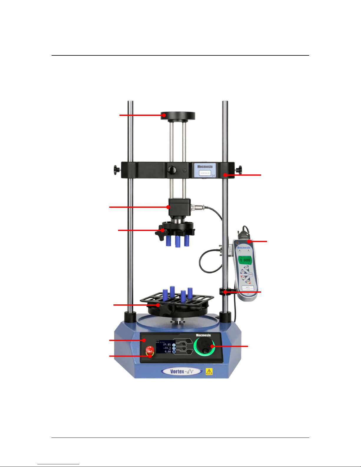
2. Vortex-dV System Diagram
Multi-
function scroll
wheel
Front control panel
Emergency stop
Lower fixing plate
(optional) shown
with saddle plate
Crosshead
Static torque
transducer
Upper
fixing
plate (optional)
AFTI mounting
bracket
AFTI
Top load tray
Page 7

7 Mecmesin Vortex-dV Operating Manual
3. Initial Setup
Unpacking the Test Stand
When you first receive the stand, please check that there is no visible damage to the
packaging. If there is any sign that the packaging or the test stand itself has been
damaged, please contact Mecmesin or your authorised distributor immediately. Do not
use the stand until you have done so.
We strongly recommend that the packaging is retained, as this can be useful if the
machine needs to be returned for calibration.
Section 1 lists items that should be included with your test stand. Please contact
Mecmesin or your authorised distributor if any items are missing or damaged.
Lifting the Test Stand
The unpackaged weight of the test stand is given in the Specification table at the back of
this manual. Do not try to lift heavy loads unaided. Use suitable lifting equipment if
necessary.
Environment Conditions
In line with BS EN 61010-1 it is recommended that your Mecmesin Vortex-dV test stand
is operated in an environment that matches the following conditions:
Indoor use only, recommended to be operated in a lab environment.
Altitude up to 2 000 m,
Temperature range between 10 °C to 35 °C. Please note that the instrument should
not be used for long durations at higher temperatures.
The maximum relative humidity is 80 % for temperatures up to 31 °C decreasing
linearly to 50 % at 40 °C. It is crucial that the surrounding environment does not cause
water to form on the device.
Mains supply voltage fluctuations up to a maximum of ±10 % of the nominal voltage.
The environments should also take considerations of excessive dust or metal
particulates as ingress of these into the device can cause damage to the system.
Locating the Stand
The test stand should be positioned on a suitable, level, stable work surface.
Page 8
Vortex-dV Operating Manual Mecmesin 8
Mains Power Supply
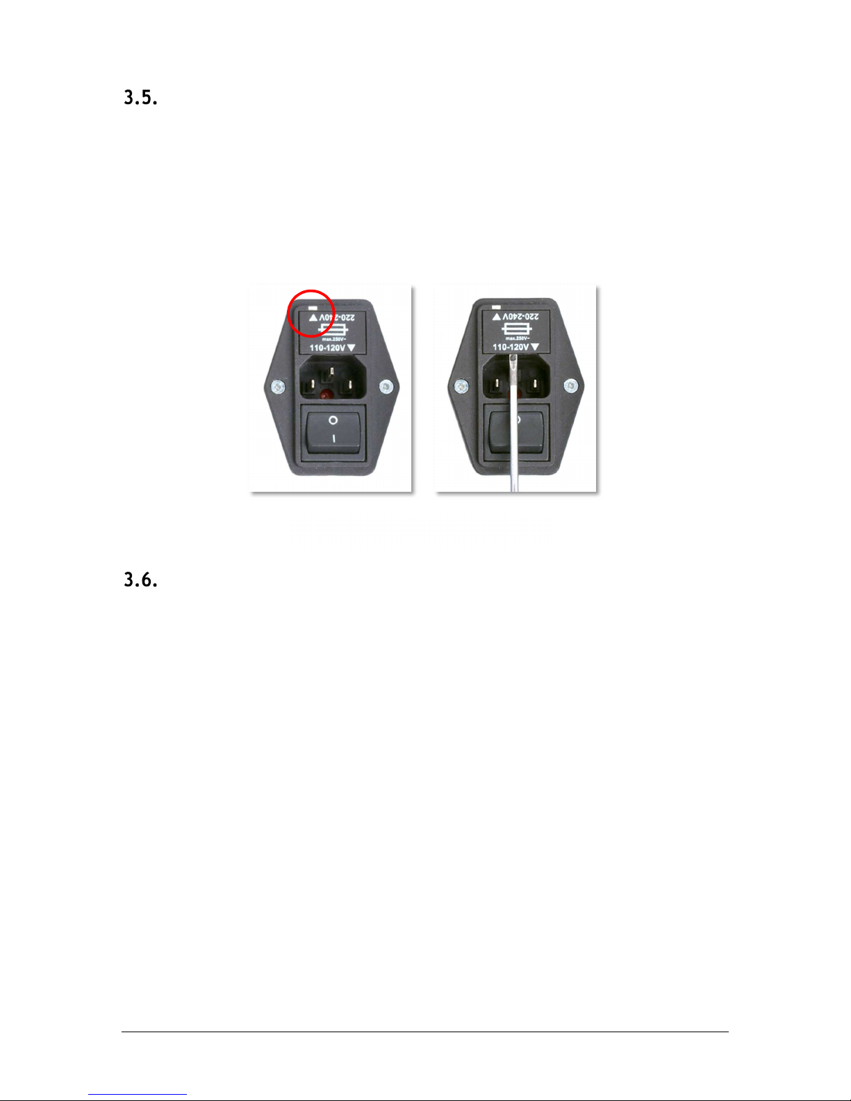
Vortex-dV test stands can be used on 110–120 or 220–240 Vac 50-60 Hz supplies. The rear
fuse carrier is set for your local requirement but is reversible, so should you replace a
fuse, the correct local voltage must be selected.
The voltage that is selected is indicated by which the arrow is pointing to the white line
located at the bottom of the device. This is illustrated in the image below, shown within
the red circle:
Fuse Specification
A Vortex-dV test stand uses two 2A - Speed T, 5 x 20mm fuses. If replacing a blown fuse
only replace the fuse on the active side of the inlet filter with the fuse specified above,
or equivalent.
If you are in doubt, please contact your local Mecmesin support agent for more
information.
Removing the fuse holder
Page 9
9 Mecmesin Vortex-dV Operating Manual
Attaching the Torque Sensor
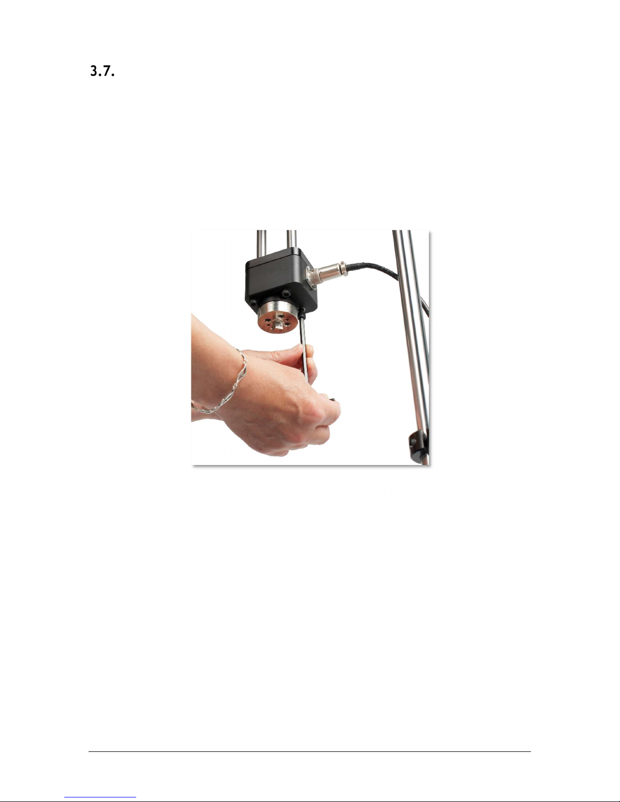
The torque cell attaches to the crosshead using the four supplied M6 caphead screws.
To fit the torque cell, first, ensure that the cable exit is towards the side that you plan to
fit the AFTI.
Then, align the transducer with the mounting plate and secure using one the M6 bolts,
if needed have one person hold the transducer while the other fits the screws. Make sure
the transducer is seated centrally before fulling tightening all of the screws.
Note: Take care when handling lower capacity torque transducers, as damage can occur
from mishandling.
It is also essential to ensure that the attached grips and fixtures cannot cause excess
leverage on the torque transducer or exhibit excessive axial load on the transducer.
Tightening the four M6 screws to secure the transducer
Page 10
Vortex-dV Operating Manual Mecmesin 10
Fitting the AFTI Torque Indicator
The AFTI can be fitted to either the left or right-hand of the test stand, but it is important
to ensure that the cable coming from the transducer points to the side that the gauge is
mounted, as this prevents any unnecessary kinking.
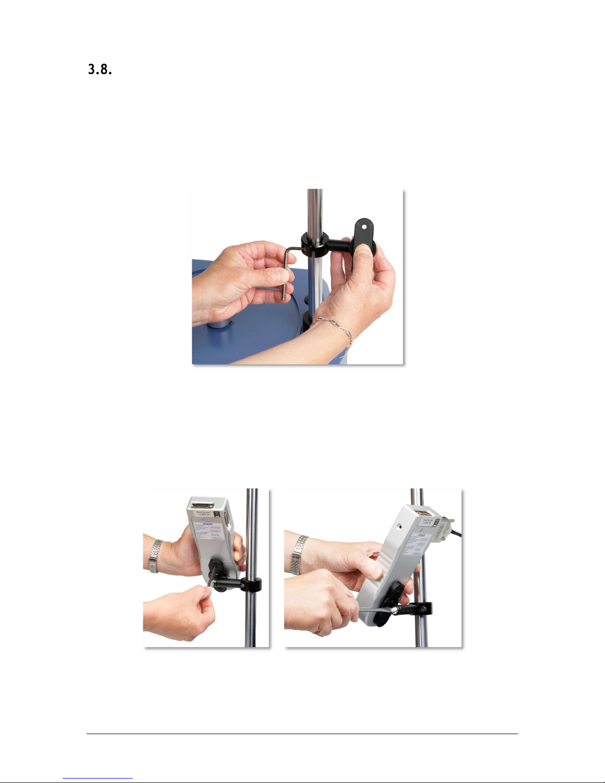
The fixing bracket can be easily fitted, adjusted or removed and transferred to the
opposite column using a 4 mm Allen key to loosen the retention screws.
To fit the AFTI to the bracket use the two supplied screws. These pass through the
bracket into the back of the gauge and are secured using a 4mm Allen key. The angle
the AFTI sits at can be adjusted by loosening the screw located on the side of the bracket.
Fitting the AFTI bracket using a 4mm Allen key
The left
-
hand image shows the AFTI being secured to the bracket, while
the image on the right shows how to adjust the angle of the AFTI.
Page 11
11 Mecmesin Vortex-dV Operating Manual
Connecting the AFTI and the Vortex-dV
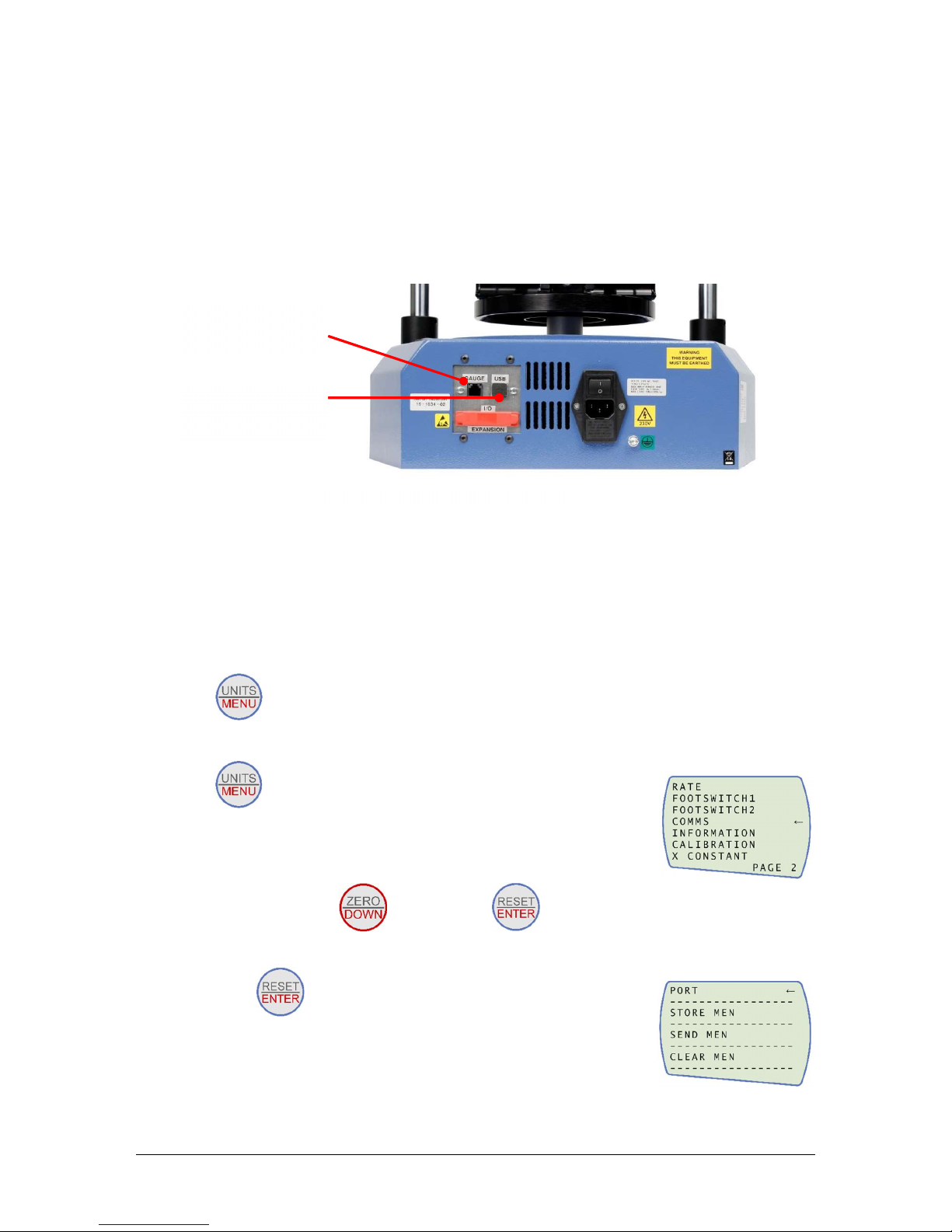
First, connect the transducer to the side port of the AFTI, using the cable from the
transducer.
Connect the top port of the AFTI to the RJ11 port marked ‘Gauge’ on the back of the
Vortex-dV, using the supplied cable, part no. 351-092. This cable enables AFTI torque
control testing and passes the torque readings to the Vortex-dV.
Note: The gauge can also be run from its power supply rather than internal batteries.
AFTI Communication Settings
To achieve communication between your Vortex–dV test system and your AFTI gauge
you need to apply the correct settings within the AFTI’s communication menu (BAUD
rate must be 115200). Use the following steps to configure the AFTI:
1. Hold on the AFTI until the main menu is displayed →
2. Press once until you are on page 2 →
3. Scroll down using the button, then press to select the “COMMS”
menu →
4. Now press on port →
USB-B Comms port
RJ11 connector
for AFTI gauge
Rear view of
Vortex
-dV
Page 12
Vortex-dV Operating Manual Mecmesin 12
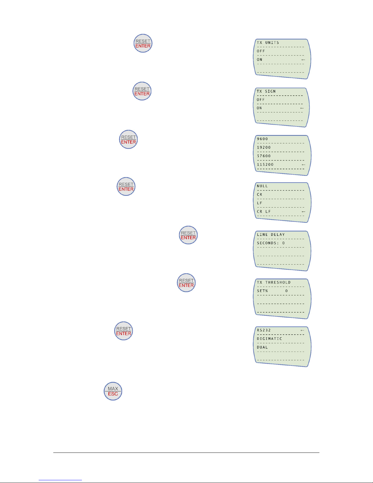
5. Set TX Units On press →
6. Set TX Sign On press →
7. Set 115200, press →
8. Set CR LF press →
9. Ensure the line delay is set to 0 press →
10. Ensure TX threshold is set to 0 press →
11. Set RS232 press →
12. Then press twice to return to the primary measurement screen.
Note: If using the stand in conjunction with VectorPro please ensure that the units
selected on the gauge match the unit selected within the software.
Page 13
13 Mecmesin Vortex-dV Operating Manual
Connect the Test Stand to a PC (VectorPro™ Users Only)
If you are using VectorPro software, connect the USB B port, located on the test stand,
to a PC using cable part no. 351-093.
Important! Please install VectorPro software on your desired PC before
connecting the test stand to your computer. Once the software is installed
and the stand is connected, the stand will show as connected. This is shown
in the image to the left.
Cable Management
It is essential that no cables interfere with the controls or any moving parts. Failure to
do so could lead to injury or damage to the equipment.
Attaching Grips and Fixtures
The most commonly-used upper fixture used is the 100 mm upper fixing plate with a
diameter capacity of 10 mm to 78 mm. This is fixed to the adaptor on the torque
transducer using a 2.5 mm Allen key to secure the four countersunk screws supplied.
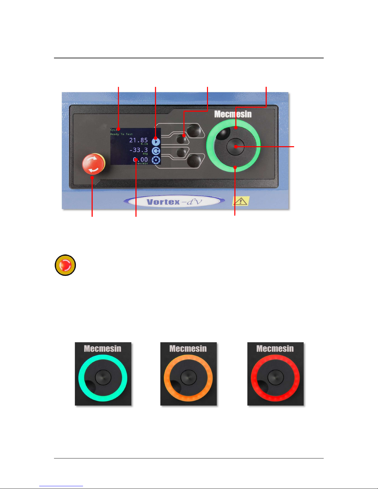
The fixture can also be quickly removed using the two grub screws in the adapter,
accessed through slots in the sides of the fixing plate, as shown below.
The most commonly-used lower fixture is the 188 mm diameter lower fixing plate with
a diameter capacity of 10 mm to 190 mm. This is fixed to the Vortex-dV spindle using a
2.5 mm Allen key to secure the four countersunk screws supplied.
A range of other torque testing fixtures is available, including saddle plates that help
support samples in the fixing plates, longer grip fingers, mandrels, and chucks.
Important! Take care not to apply excess torque on the transducer when securing the
fixtures.
Page 14

Vortex-dV Operating Manual Mecmesin 14
Test Stand States
The test stand can be in one of five states:
1. Test readiness - ready to start, or complete,
2. Testing – test operation sequence is running,
3. Stopped - test interrupted or emergency stop pressed,
4. Jog mode - for jogging or positioning the crosshead manually,
5. Settings menu – for adjusting your test stands settings,
In each state, the selector buttons have functions described by the on-screen icons.
Page 15
15 Mecmesin Vortex-dV Operating Manual
4. Front Panel Controls
Emergency Stop Button
Push to stop the spindle movement. Rotate the button to release it and resume
spindle control. If pressed during a test, do not simply restart a test, ensure you
remove any residual torque using the test stand’s jog controls.
Dial control
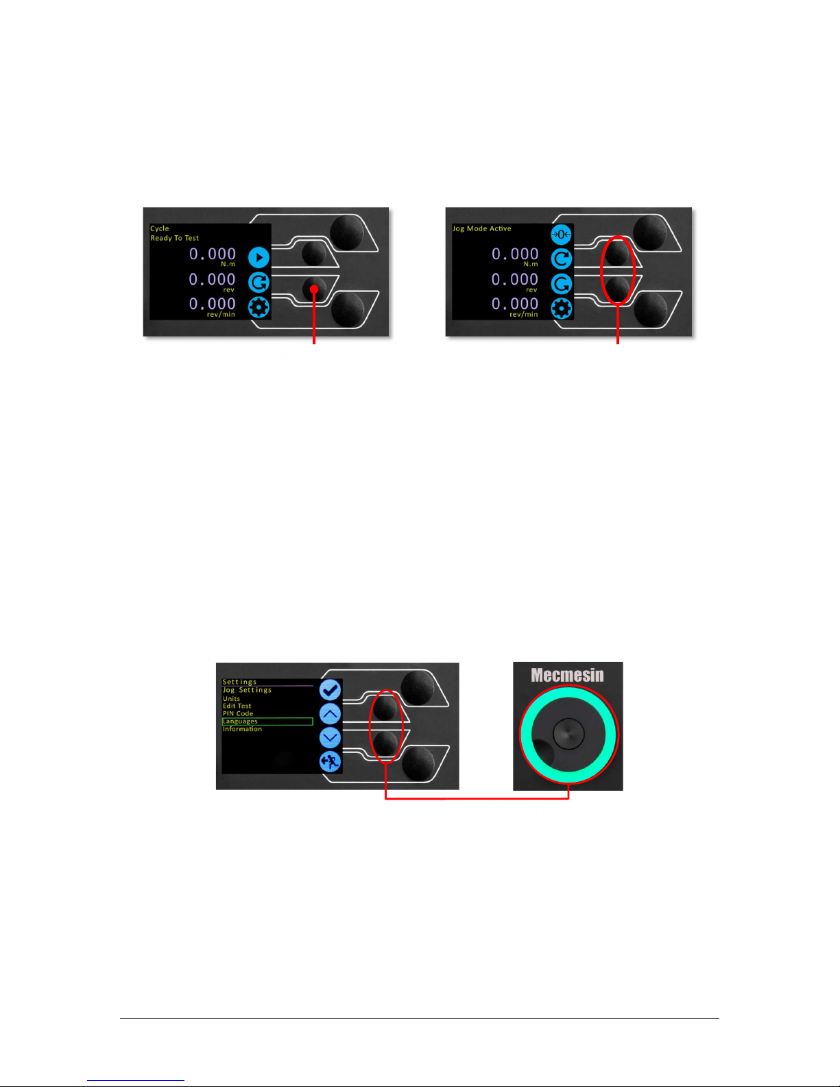
The lights
The lights surrounding the wheel illuminate in three colours, indicating the status of the
test stand:
Multi
-
function
scroll wheel
LED dial ring
Scroll
wheel
button
Emergency stop
Button
functions
Status
messages
Multi
-
function
selector buttons
Display
Green Light
Pulsating: Ready to start test
Rotating: Scrolling through a menu
Amber Light
Static: Test completed
Rotating: Spindle moving
Red Light
Static: Test stopped/limit
triggered
Page 16
Vortex-dV Operating Manual Mecmesin 16
The wheel
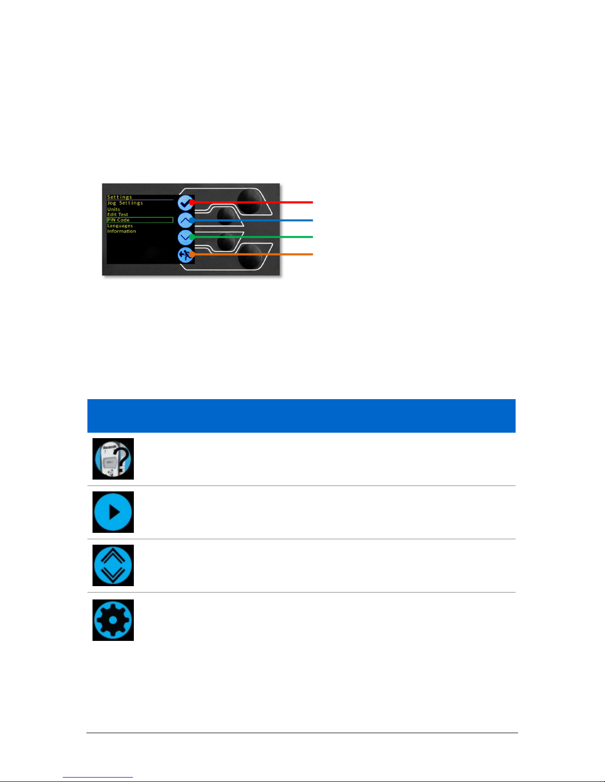
When in jog mode the wheel drives the Vortex-dV clockwise or anticlockwise, matching
the direction the wheel is turned. This method offers more variable control when
compared to the two fixed-speed jog control buttons (circled in red below).
The scroll wheel can also be used as a speed controller. The jog buttons move the spindle
at the set speeds (configured in the ‘Jog Settings’ menu picture below). Rotating the
wheel clockwise while holding a jog button increases the speed and rotating the wheel
anticlockwise while holding a jog button decreases the speed
Vortex-dV test stands also feature a precision jog mode, rotating the scroll wheel while
holding the central scroll wheel button moves the test stand at its minimum speed; this
is useful when fitting specimens into grips for example.
Navigational Control
The scroll wheel can also be used to navigate the menus. When in a selection menu, the
scroll wheel cycles through the selections and their values. This is an alternate
navigational option to using the up and down arrow buttons.
The button
The central button is used to confirm a menu selection. It is equivalent to the tick button.
It can also be used to activate fine jog control, by rotating the scroll wheel while holding
the central scroll wheel button moves the test stand at its minimum speed.
Enter jog mode
Jog control buttons
Menu: operates with buttons or wheel
Page 17
17 Mecmesin Vortex-dV Operating Manual
Vortex-dV Display Panel
The display indicates the stand’s status, displays live values and is used to configure the
test stands settings.
The purpose of the four multi-function button is indicated on screen by an adjacent icon.
Below is an image showing a typical example of the on-screen icons in relation to the
physical buttons.
On-Screen Icons
On-screen icons vary depending on the current state of the test stand and what functions
the physical buttons perform at that point. Below are reference tables to help explain the
icon definitions, in relation to the test stand state.
1. Test Readiness
Icon Action
No AFTI connected.
Start test sequence.
Go to jog mode.
Go to settings.
Top
button is ‘confirm’
Upper middle button is ‘up’
Lower middle button is ‘down’
Lower button is ‘back’
Page 18
Vortex-dV Operating Manual Mecmesin 18
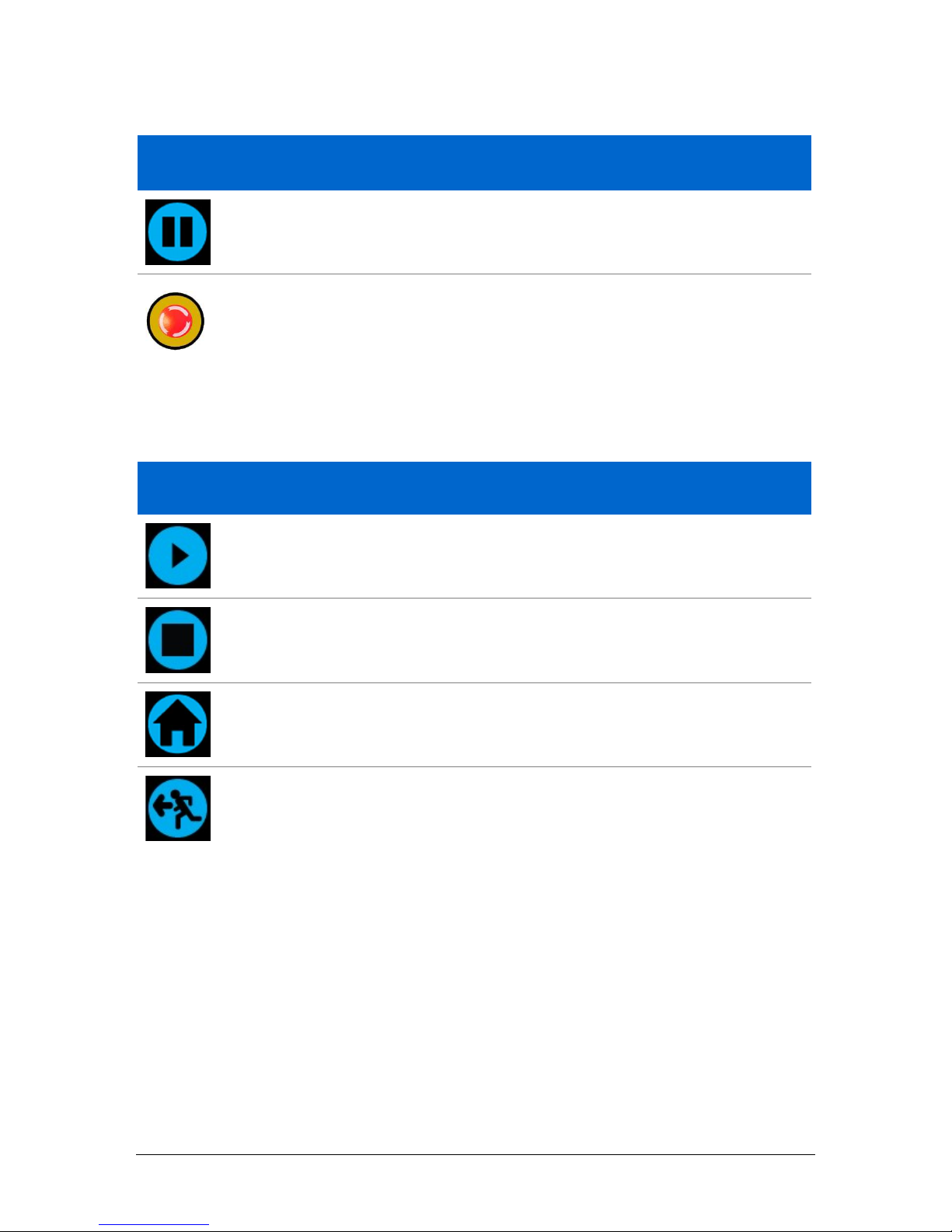
2. Testing
Icon Action
Pause test: This stops spindle movement, leaving the stand in a state of
test readiness. The message is ‘Interrupted: User’ and the play button is
displayed as well as the stop button.
Emergency stop button pushed: Message: ‘Emergency Stop!!!’. Release
the emergency stop to regain control and remedy the situation before
resuming testing. Note there is no on-screen icon for the emergency
stop.
3. Stopped
Icon Action
Continue test sequence.
Stop test: This ends the test at this point
Move to the home position (start position from the beginning of the
previous test). This icon is only visible after pressing the stop
Exit to the test ready screen, leaving the spindle in its current position.
Page 19
19 Mecmesin Vortex-dV Operating Manual
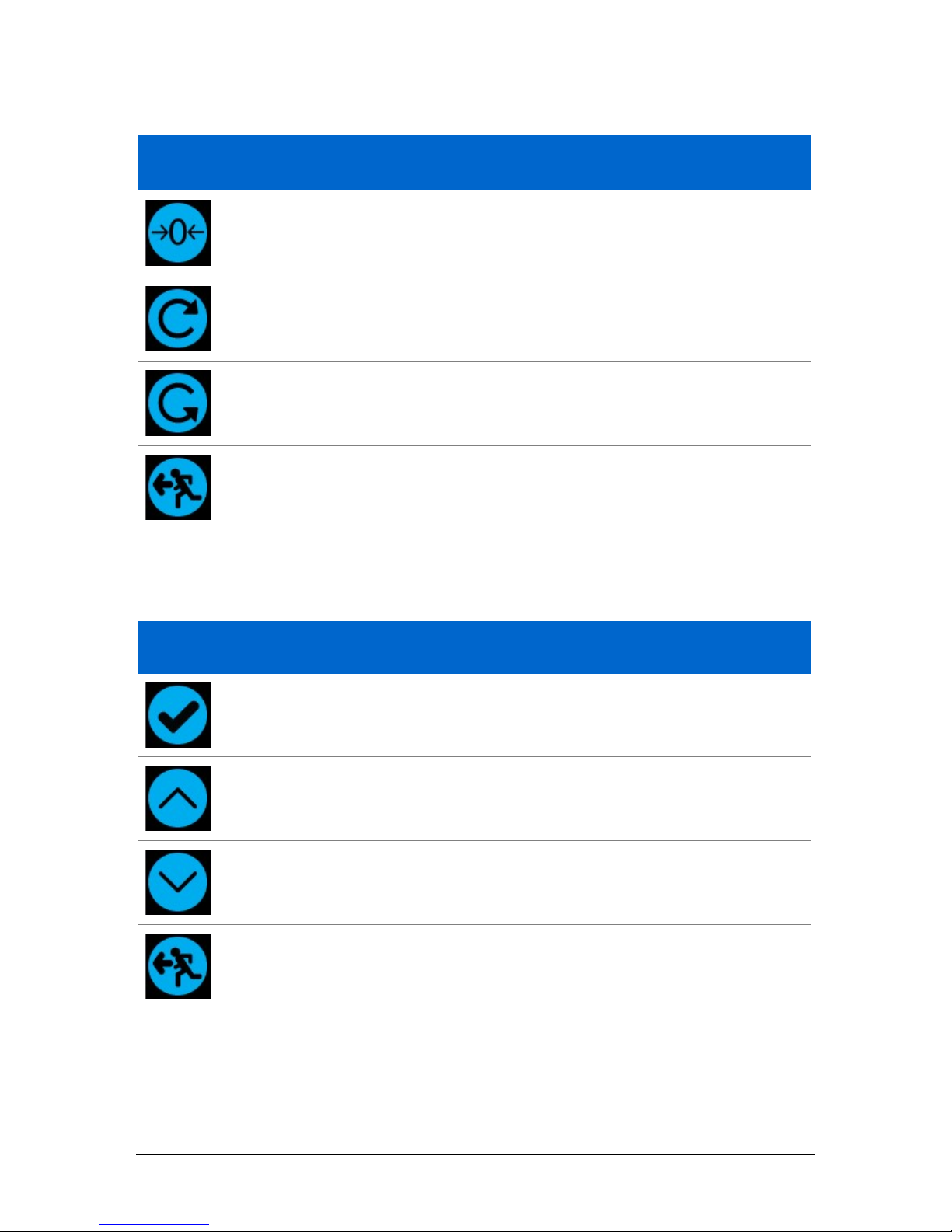
4. Jog Mode
Icon Action
Zero (tare) all system values.
Rotate the Vortex-dV clockwise at the set jog speed.
Rotate the Vortex-dV anticlockwise at the set jog speed.
Go back to the previous screen.
5. Settings Menu
Icon Action
Confirm selection (or press the scroll wheel button).
Navigate up a menu selection or value (or turn the wheel clockwise).
Navigate down a menu selection or value (or turn the wheel
anticlockwise).
Go back to the previous screen.
Page 20
Vortex-dV Operating Manual Mecmesin 20
5. Vortex-dV Settings
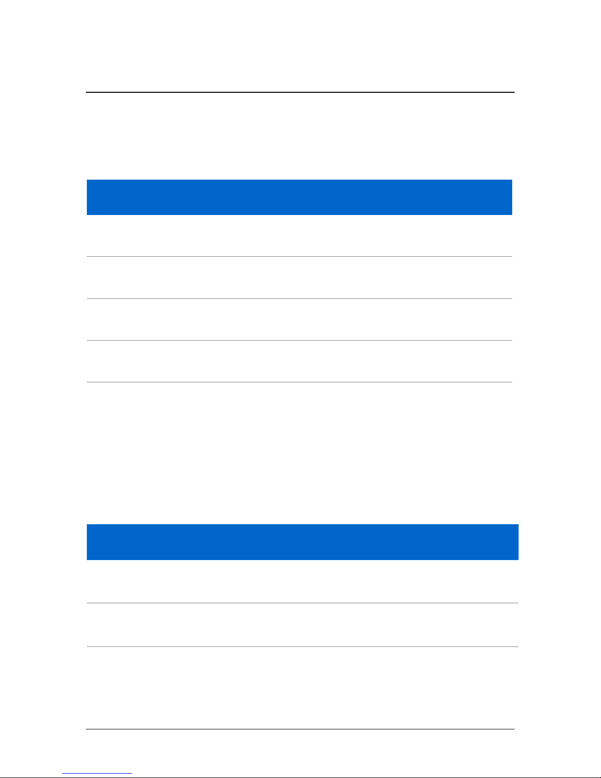
Settings: Jog settings
Within the jog settings menu, you can configure the jog speed limits while in jog mode.
Below is a detailed breakdown of each setting and the options available for each setting.
Setting Action Range
Clockwise Speed
Configure the jog speed in a clockwise direction
0.1 to 30
rev/min
Anticlockwise
Speed
Configure the jog speed in an anticlockwise direction
0.1 to 30
rev/min
Clockwise Limit
Configure the clockwise torque limit while in jog mode 0 to 10 N.m
Anticlockwise
Limit
Configure the anticlockwise torque limit while in jog
mode
0 to 10 N.m
Tare AFTI
Configure whether or not the AFTI is tared when pressing
the tare button in jog mode.
Yes or No
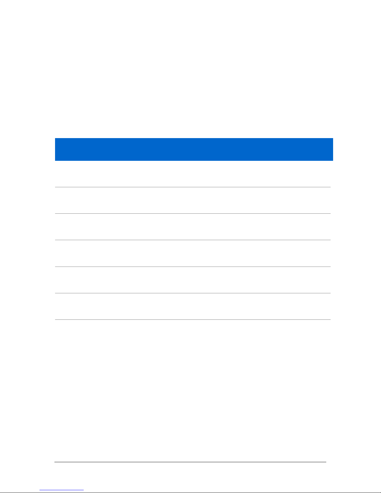
Settings: Units
Within the units menu, you can configure the test stands units for displacement and
speed. Torque settings are configured using the AFTI.
Setting Units Available
Angle rev, deg
Speed rev/min, rev/sec, deg/min, deg/sec
Torque N.m, N.cm, mN.m, gf.cm, kgf.cm, kgf.m, lbf.ft, lbf.in, ozf.in
Page 21
21 Mecmesin Vortex-dV Operating Manual
Settings: Edit Test
Important
For more information relating to ‘Start Direction’ and ‘Move to Start’, please see Vortex-
dV Operation Sequence and Move to Start.
Cycle (by Angular Displacement)
In a cyclic test, the spindle moves between two reference angles that are relative to tared
zero.
Setting Options
Cycle Count 0-9999
Clockwise Speed 0-30rev/min
Anticlockwise Speed 0-30rev/min
Clockwise Angle
A positive value is clockwise from tared zero and a negative value is
below
Anticlockwise Angle
A positive value is clockwise from tared zero and a negative value is
below
Start Direction Choose whether the test direction is clockwise or anticlockwise
Move to Start Select if the test moves to the start position first
Example
Clockwise Angle: +1000°
Anticlockwise Angle -30°
Initial stroke: Clockwise
Move to Start: Yes
Unless already at -30° the spindle will first travel to that point. The stand will then move
to +1000° from tared zero, followed by a final movement back to -30°.
Page 22
Vortex-dV Operating Manual Mecmesin 22
AFTI Control/Torque Control
The AFTI control test operation consists of two main functions:
AFTI Control - Control of the test stand using the AFTI’s limit or break settings,
Torque Control - Control of the test stand using the front panel to program limit,
break or cycle settings,
Within AFTI Control/Torque Control there are four subtests:
Sub-Test Description
AFTI Control
Move in a set direction until a torque limit or break condition is hit
and then stop. Configured using the AFTI.
Torque Limit
Move in the configured direction until a torque limit is hit and then
stop. Configured using the front panel.
Torque Cycle
Cycle between a limit torque and a return torque. Configured using
the front panel.
Break
Move in the configured direction until a break condition is detected.
Configured using the front panel.
AFTI Control Test
With an additional cable (351-092), a Mecmesin AFTI gauge can be used to set torque
limits to control stand movement.
Torque setpoint, action (reverse/stop) are all set on the gauge under the ‘STAND’ menu.
Here you can select the action when the limit is reached; ‘REVERSE’ or ‘STOP’ and the
type of control limit ‘BREAK’ or ‘LIMIT’.
Please note for cyclic tests the front panel torque control must be used. AFTI cycling is
not compatible with Vortex-dV test stands
Example Test Setup
1. On the test stand’s front panel under ‘Edit Test’ select the test type ‘AFTI Control’
and sub-type ‘AFTI Control’,
2. Configure the speed and direction settings located within the ‘Edit Test’ menu,
3. On the AFTI gauge hold
Page 23
23 Mecmesin Vortex-dV Operating Manual
4. On page one of the AFTI menus select ‘STAND’ using the button,
5. Next select the action when the limit is hit, either ‘REVERSE’ or ‘STOP’. For
reverse you need to select the reverse direction either ‘UP’ or ‘DOWN’,
6. Once the action has been selected configure the limit control. This limit can be
either a ‘BREAK’ condition or torque ‘LIMIT’. For ‘BREAK’ set the break
threshold, for ‘LIMIT’ select the limit torque,
Torque Control Test – Torque Limit, Torque Cycle and Move to Break
Torque control tests can be used to set torque limits or a break condition to control stand
movement. Within the three sub-tests (Torque Limit, Torque Cycle and Move to Break)
the following settings are available, please note some of the settings are specific to the
test type:
Setting Options
Up Speed 0-30 rev/min
Down Speed 0-30 rev/min
Start Direction Choose whether the test direction is clockwise or anticlockwise.
Test Sub-Type Select the test sub-type (Options are listed above).
Limit Torque Limit and Cyclic Tests Only - Enter the target torque for the test.
Return Torque Cyclic Tests Only - Enter the start torque for the test
Cycle Count Cyclic Tests Only - Enter the number of cycles to be completed
Break Threshold
Enter the break threshold (percentage of the torque cells capacity
that the test value needs to be above for a break condition to be
detected).
Page 24

Vortex-dV Operating Manual Mecmesin 24
Examples
Torque Limit
Speed: 5 rev/min
Start Direction: Anticlockwise
Test Sub-Type: Torque Limit
Limit Torque: 5 N.m
The stand moves anticlockwise at 5 rev/min until the applied torque is 5 N.m from tared
zero, once the limit torque is reached the test stops.
Torque Cycle
Clockwise Speed: 10 rev/min
Anticlockwise Speed: 20 rev/min
Start Direction: Clockwise
Test Sub-Type: Torque Cycle
Limit Torque: 2 N.m
Return Torque: 0.5 N.m
Cycle Count: 10
The stand moves clockwise at 10 rev/min until the applied torque is 2 N.m from tared
zero. Once the limit torque is reached the stand moves anticlockwise at 20 rev/min until
a torque of 0.5 N.m is reached, this cycle repeats 10 times at which point the test stops.
Break
Clockwise Speed: 2 rev/min
Anticlockwise Speed: 30 rev/min
Start Direction: Clockwise
Test Sub-Type: Break
Break Threshold: 5 %
The stand moves clockwise at 2 rev/min until a break condition is detected. The break
event must also occur above 5% of the connected torque cell’s capacity.
Page 25
25 Mecmesin Vortex-dV Operating Manual
Data Capture within VectorPro™
To use AFTI Control/Torque Control tests in conjunction with VectorPro first program
the test settings using the stand’s front panel and/or AFTI and then create a VectorPro
test using the AFTI/Torque control operation, ensuring the speed and test orientation
match your configuration.
Please note the speed and test direction use the settings configured within VectorPro,
while other test settings are loaded from the front panel. For more information please
refer to the VectorPro user manual, part no. 431-955.
At the end of a test, or in a stopped condition, you may need to move the
crosshead to clear a sample, or the drive spindle to remove a torque.
Never restart a test from a stopped condition with a residual torque, and
always Reset the gauge before a subsequent test.
If the AFTI is switched off or loses power during an active test in AFTI Control mode,
the drive spindle will stop.
Page 26

Vortex-dV Operating Manual Mecmesin 26
Half Cycle
A half-cycle test is to an angular displacement relative to tared zero. A cycle starts when
the crosshead is at the first displacement position and ends back at the second position.
Setting Options
Cycle Count
0-8000
Clockwise Speed 0-30rev/min
Anticlockwise Speed 0-30rev/min
Clockwise Angle
A positive value is clockwise from tared zero and a negative value is
below
Anticlockwise Angle
A positive value is clockwise from tared zero and a negative value is
below
Start Direction Choose whether the test direction is clockwise or anticlockwise
Move to Start Select if the test moves to the start position first
Example
Clockwise Angle: +180°
Anticlockwise Angle -90°
Initial stroke: Clockwise
Move to Start: Yes
Unless already at -90° from tared zero, the spindle will travel to that point and then move
to +180° from tared zero, and stop.
Page 27

27 Mecmesin Vortex-dV Operating Manual
Vortex-dV Operation Sequence and Move to Start
Vortex-dV operations, such as the half cycle consist of two datum points, a clockwise
angle and anticlockwise angle.
For operations with the primary movement being clockwise, the following is true:
The ‘Anticlockwise Angle’ is the start position for the test and the ‘Clockwise
Angle’ is the finishing position.
For operations with the primary movement being anticlockwise, the following is true:
The ‘Clockwise Angle’ is the start position for the test and the ‘Anticlockwise
Angle’ is the finishing position.
Within the ‘Edit Test’ display on your test stands front panel there is an option called
‘Move to Start’, setting this feature to ‘Yes’ means that the stand always moves to the
start position.
In some instances, this means the first direction of movement is opposite to the primary
test movement. Jog settings
Settings: PIN Code
Within the PIN code menu, it is possible to set a four-digit number that can be used to
lock the menu feature of your Vortex-dV. Please note once this has been set you cannot
access the menu without the PIN, so it is crucial that you keep a record of this safe. If the
PIN code has been set and then lost or is unknown, please contact your local agent or
Mecmesin Technical Support
Settings: Languages
Select your desired language. Upon confirmation, you are returned to the settings menu
in the language chosen.
Settings: Information
This screen is used to display vital information relating to your Vortex-dV and connected
devices. Here you can see hardware and firmware properties.
Page 28
Vortex-dV Operating Manual Mecmesin 28
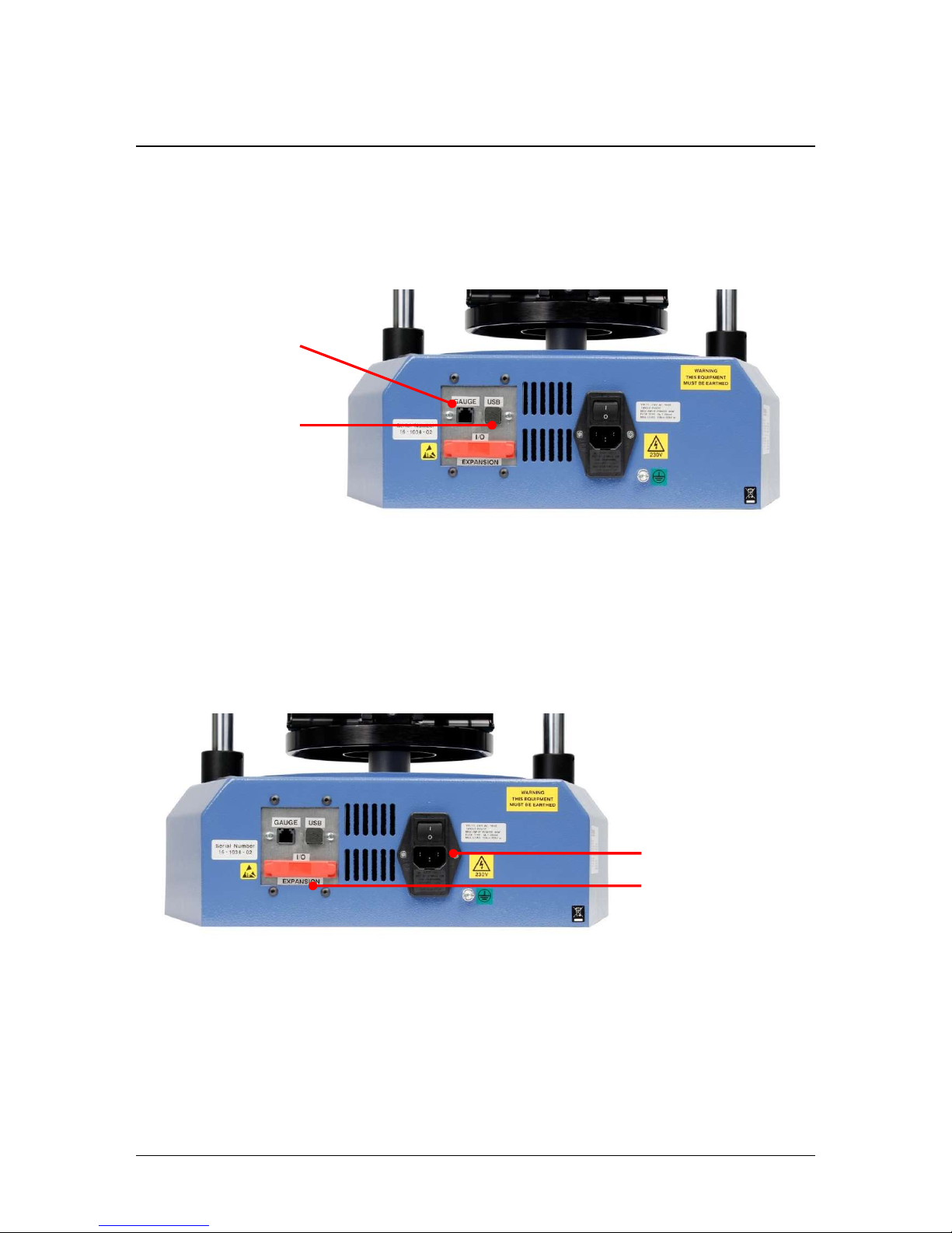
6. Rear Connectors Panel
USB-B Comms port
RJ11 connector for
AFTI gauge
Inlet mains filter
and on/off switch
Digital IO port
(Not currently
implemented)
Page 29
29 Mecmesin Vortex-dV Operating Manual
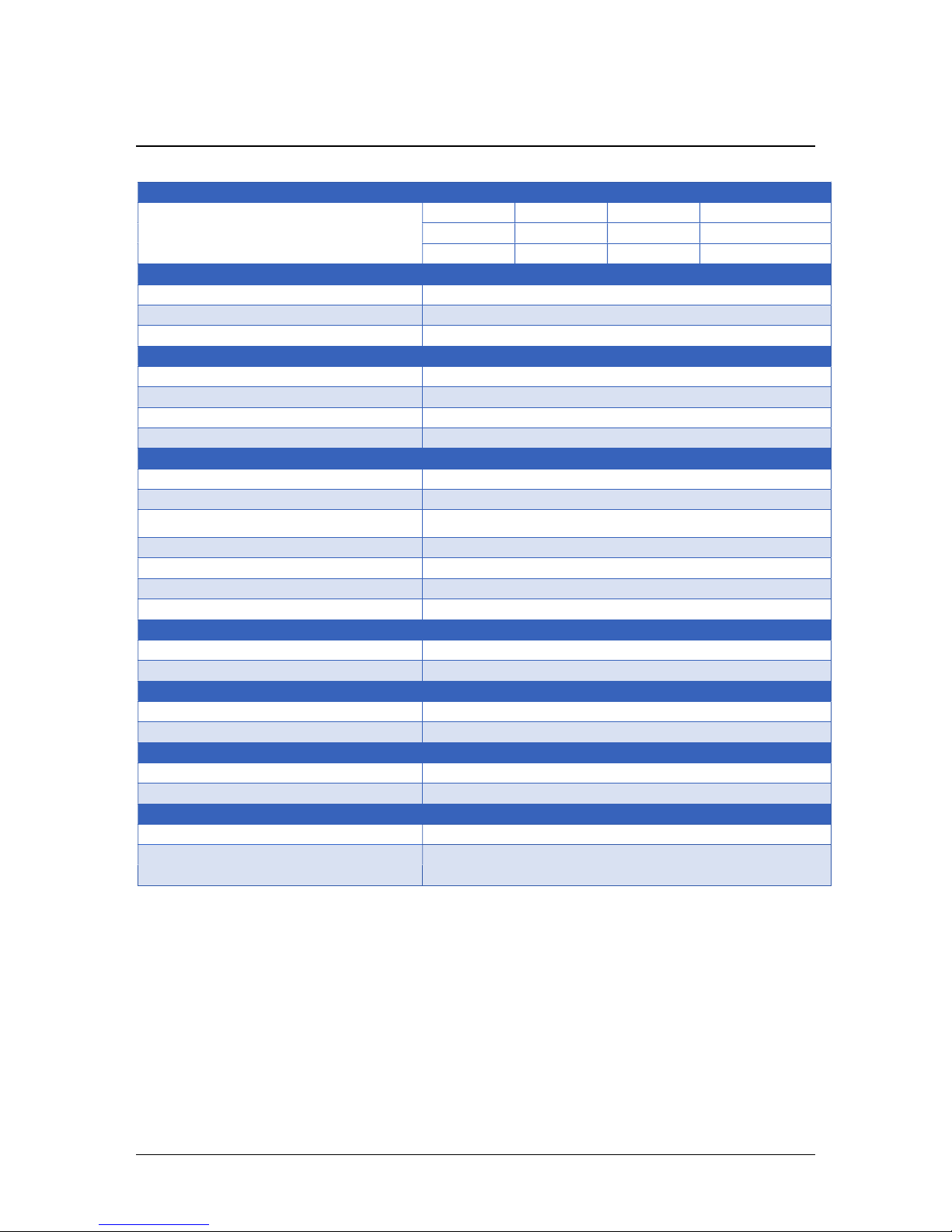
7. Vortex-dV Specification
Vortex-dV
Rated capacity kN
N.m 0–1.5 0–3.0 0–6.0 0–10.0
kgf.cm 0–15 0–30 0–60 0–100
lbf.in 0–13 0–26 0–52 0–90
Position
Maximum rotation 8000 revs
Positional accuracy 0.2° per 36,000°
Positional resolution 0.1º (0.001 rev)
Speed
Speed range rev/min 0.1 to 30
Speed accuracy ±0.1% of indicated speed
Resolution 0.1º (0.001 rev)
Maximum number of cycles per test 9999
Dimensions
Height 781 mm (30.7 ")
Width 390 mm (13.4")
Maximum travel of adjustable transducer
carriage
182 mm (7.2")
Maximum headroom 505mm (19.9") [448 mm (17.6")]*
Weight 19.5 kg (48 lb)
Capacity of lower mounting table 10 - 190 mm (0.39 - 7.5”)
Capacity of upper mounting table 10 - 78 mm (0.39 - 3.07”)
Electrical supply
Voltage 230 V AC 50 Hz or 110 V AC 60 Hz
Maximum power requirement 100W
Torque Measurement
Torque accuracy 0.5% of full scale
Torque units mN.m, N.m, kgf.cm, lbf.in, ozf.in (as per AFTI)
Environment specification
Operating temperature 10°C – 40°C (50°F – 100°F)
Operating relative humidity Normal Industry and laboratory conditions
Display & Data Output
Front Panel Display Indication Load / Displacement / Speed
Output of Test Results
Stand
Via USB (VectorPro™ Software - PDF, XLXS, CSV, TXT, Email and Images)
* With upper and lower mounting tables fitted
Page 30
Vortex-dV Operating Manual Mecmesin 30
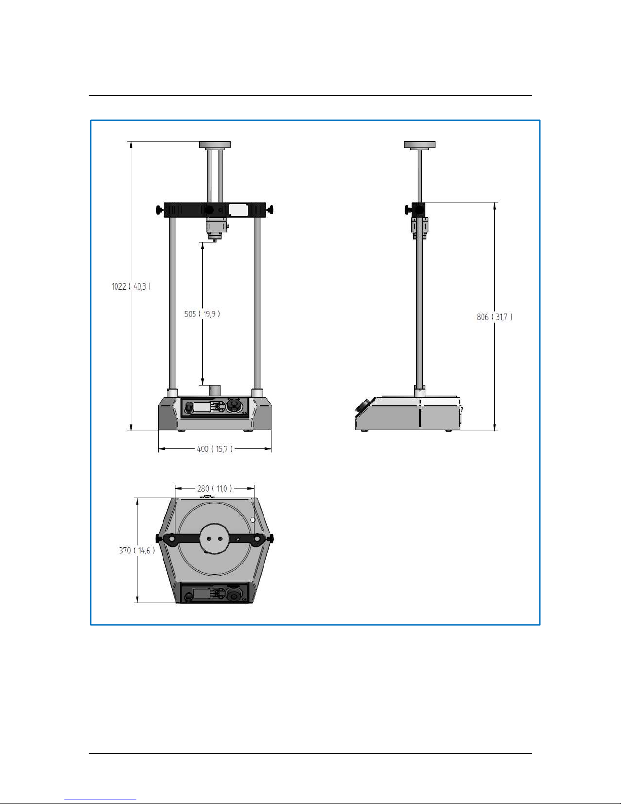
8. Vortex-dV Dimensions
Vortex-dV Dimensions
mm (inch)
Page 31
31 Mecmesin Vortex-dV Operating Manual
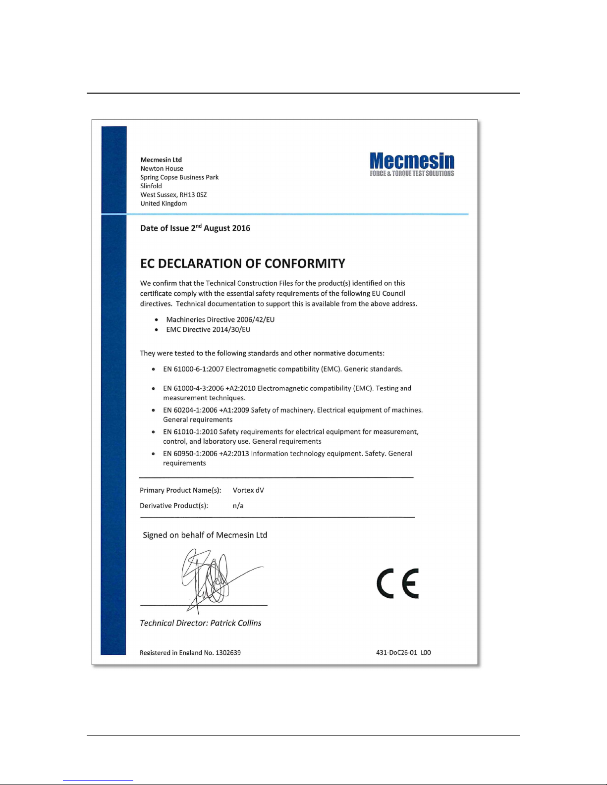
9. Declaration of Conformity
Page 32

Vortex-dV Operating Manual Mecmesin 32
10. Change Log
The latest production firmware release for Vortex-dV devices is 3.0.10, this section
documents the changes at each production firmware release from version 2.0.11 to
3.0.10.
Please note for version numbers not listed below the changes are included with the next
version, for example, bug fixes in versions 3.0.4 to 3.0.5 are listed under in 3.0.6.
All releases include performance enhancements and bug fixes to improve the use
experience. Not all bug fixes are detailed here.
2.0.12 - New Features
N/A
2.0.12 - Bug Fixes
Correction to AFTI Min/Max reset command.
3.0.2 - New Features
Additional menu item ‘Information’ screen has been added,
Major Feature! User selectable PIN protection for the test stands menus added,
Major Feature! ‘Home’ button added to return the stand to the last tared position at
the end of the test,
Major Feature! Within the jog settings, you can now to choose whether or not to tare
the AFG/AFTI when pressing the stand’s tare button,
Major Feature! In the ‘Edit Test Settings’ menu, the user can select the test start
direction and whether or not the stand moves to the start position at the beginning
of the test,
Major Feature! On ‘AFG/AFTI’ controlled tests, the return position will now be the
test start position rather than the limit switch position,
Major Feature! AFG/AFTI stand control torque limits now also work in jog mode,
this can be used to protect damage to the system while jogging,
Major Feature! You can now use the front panel control to pause, stop or continue
the test,
Swedish language option added,
Polish language option added.
Page 33

33 Mecmesin Vortex-dV Operating Manual
3.0.2 - Bug Fixes
N/A.
3.0.5 - New Features
Major Feature! Add new command for setting the home position. This is exposed in
VectorPro 5.1.2.0,
The text for the jog settings menu has changed to CW/ACW torque limit,
Additional AFTI control.
3.0.5 - Bug Fixes
Jog mode on Vortex-dV is too fast (oversensitive),
Vortex-dV reverse cycle count issue fixed,
Corrected inversion of AFTI control signals in AFTI control test.
3.0.6 - New Features
N/A.
3.0.6 - Bug Fixes
Fixed issue where overload counts are missing from the device firmware,
Resolved issue where Vortex dV with firmware 3.0.5.0 only displays increments of
10deg/min.
3.0.7 - New Features
N/A.
3.0.7 - Bug Fixes
Fixed issue where the AFTI wasn’t tared correctly,
Test not being terminated by over temperature reading has now been fixed,
Stand not settling to 0 speed during jog mode,
Extra zero issue in torque display removed,
Page 34

Vortex-dV Operating Manual Mecmesin 34
3.0.8 - New Features
Major Feature! Torque control tests are now programmed via the front panel
(Previously via AFTI).
3.0.8 - Bug Fixes
Fixed Vortex-dV front panel decimal rounding/missing decimal issue,
Jog oscillation bug has been rectified,
dV firmware 3.0.7.0 rounding/missing decimal in force display.
3.0.10 - New Features
Force limits for AFTI added to Jog Settings,
3.0.10 - Bug Fixes
Fixes Stop/Reverse function being ignored if AFTI is not seen as connected
Fix speed settings not updating in edit test menus
Fix Load readings frozen in Move to Break test
Page 35
35 Mecmesin Vortex-dV Operating Manual
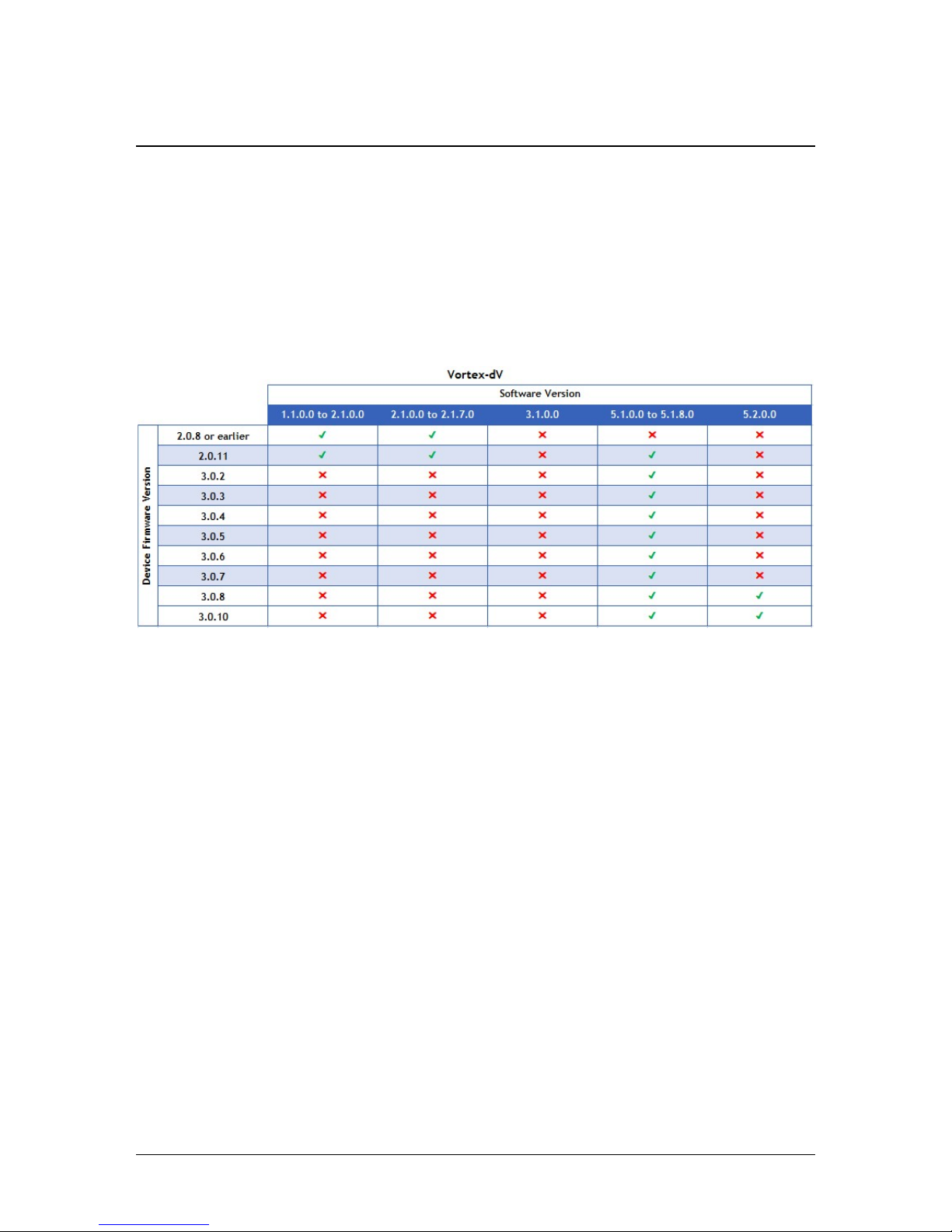
11. Test Stand Firmware/ Software Compatibility Table
The table below can be used to identify what versions of VectorPro can be used with
your test stands firmware.
To identify the firmware navigate to the information panel within the test stand’s
settings menu.
The software version can be identified by clicking the VectorPro icon located in
the centre of the top header bar or visually on the main login window.
Page 36

Vortex-dV Operating Manual Mecmesin 36
12. Operator Notes
Page 37

37 Mecmesin Vortex-dV Operating Manual
Page 38

Since 1977, Mecmesin has assisted thousands of companies
achieve
enhanced quality control in design and
production. The Mecmesin brand represents excellence in accuracy, build, service, and value. In production
centres and research labs worldwide, designers, engineers, operators, and quality managers endorse Mecmesin
force and torque testing systems for their high performance across countless applications.
www.me
cmesin.com
Mecmesin : a world leader in affordable force and torque testing solutions
The Mecmesin global distribution network guarantees your testing solution is rapidly
delivered and efficiently serviced, wherever you are.
Head Office
– UK
France
Germany
North America
Asia
China
Algeria
Argentina
Australia
Austria
Bangladesh
Belgium
Brazil
Bulgaria
Cambodia
Canada
Chile
China
Colombia
Costa Rica
Croatia
Czech Republic
Denmark
Ecuador
Egypt
Estonia
Finland
France
Germany
Greece
Hungary
India
Indonesia
Iran
Ireland
Israel
Italy
Japan
Korea South
Kosovo
Kuwait
Laos
Latvia
Lebanon
Lithuania
Macedonia
Malaysia
Mexico
Morocco
Myanmar (Burma)
Netherlands
New Zealand
Norway
Paraguay
Peru
Philippines
Poland
Portugal
Romania
Russia
Saudi Arabia
Serbia
Singapore
Slovakia
Slovenia
South Africa
Spain
Sri Lanka
Sweden
Switzerland
Syria
Taiwan
Thailand
Tunisia
Turkey
UK
United Arab Emirates
Uruguay
USA
Vietnam
 Loading...