

Page 1
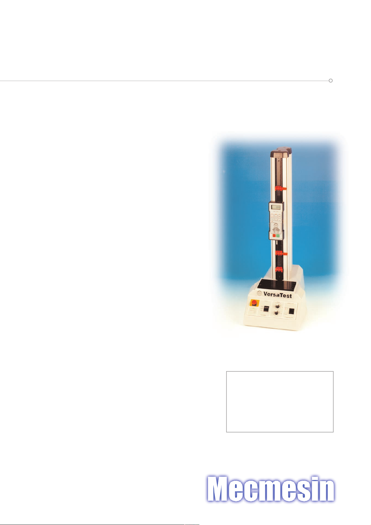
VersaTest
Motorised Test Stand
Operating Instructions
It is essential that you
familiarise yourself with the
contents of these instructions
before attempting to operate
the VersaTest.
English
S.I. Instruments
256 South Rd. Hilton
South Australia 5033
Ph (08) 8352 5511
[email protected]
www.si-instruments.com
Page 2
Thank you for choosing this Mecmesin instrument, with correct use it will give many years of reliable service. Upon receiving the unit please check
that no obvious physical damage has been sustained by the packaging material or the instrument itself. If any damage is evident, or if any of the
items in Appendix 1 are missing, please notify Mecmesin or their Authorised Agent immediately. We strongly recommend that all the packaging
and fixings are retained for any future transit requirements. When using the VersaTest, please ensure that the ventilation holes situated on the back
and the bottom of the unit are not obstructed. Attach (hand tight only) the four rubber feet to the VersaTest with the screws provided.
Appendix 2 gives guidance notes on the safe use of mains powered test frames. You should read this before proceeding any further. Within the
European Union (EU), a copy of this Appendix is supplied in a language appropriate for your country.
Failure to adhere to the guidelines for safe use given in these operating instructions may result in irrepairable damage to the unit and personal
injury to the operator.
The VersaTest is a single column ballscrew-driven test frame with a load rating of up to 2500N. It must not be used with load ratings above
2500N. Complemented by a Mecmesin loadcell or force gauge (as illustrated in the photograph), together with special fixtures and accessories, it
constitutes a key component in force measurement systems suitable for accurately and reproduceably testing a wide range of products.
There is only one standard model of the VersaTest. The dimensions, speed range and capacity have been carefully optimised to cover the test
procedures and specimen sizes most often needed by quality departments within many sectors of manufacturing industry.
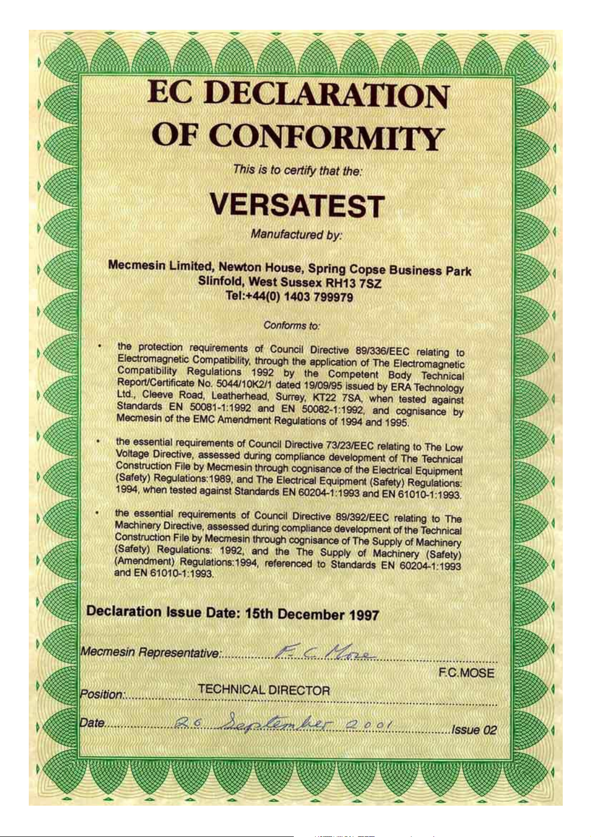
The VersaTest has been designed and manufactured in a controlled system to ensure compliance with all relevant European Community Directives.
See Appendix 3. Additional information on the VersaTest can be found in Mecmesin publication M/511291.
Speed Setting
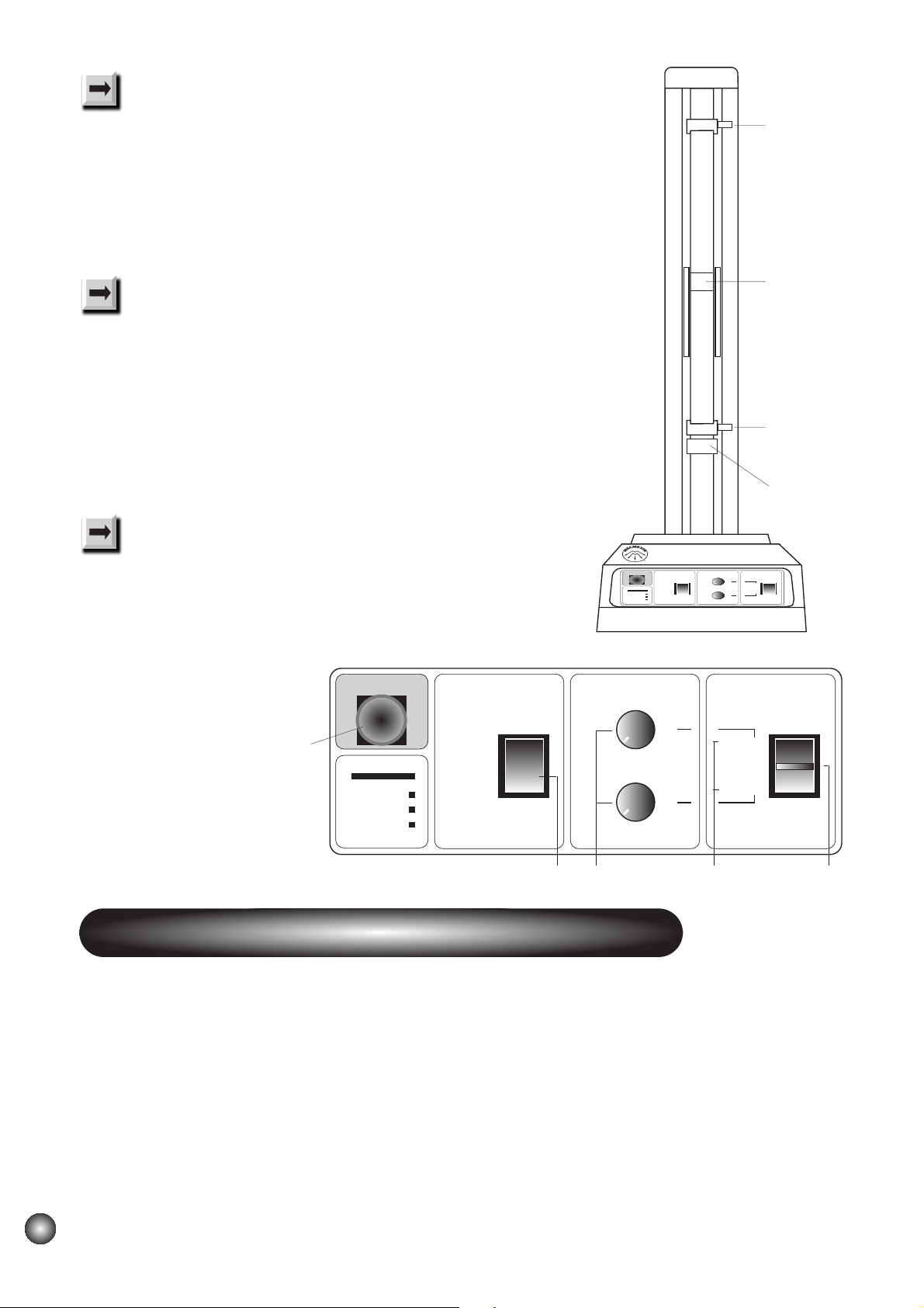
The VersaTest has variable speed control in both upward and downward directions. Speeds can be independently set and controlled by the knobs
(A, in Fig.1) on the front panel. The white pointer on the speed control knobs gives an indication of the speed setting. Some test Standards place
particular requirements upon speed accuracy/reproduceability, which may exceed the normal performance of the VersaTest. Under such
circumstances calibration of each individual test stand may be appropriate.
Start-up Procedure
Set the limit switches (B, in Fig.1); turn each red plastic thumbscrew anticlockwise, move to appropriately 50mm either side of the moving
crosshead (C, in Fig.1) and re-tighten. Do not confuse these limit switches with the (preset) safety stop (D, in Fig.1).
Connect your VersaTest to an appropriate mains supply, turn on power switch (a, in Fig.2). If the green power bar does not illuminate, turn the red
emergency stop button (E, in Fig.1) in a clockwise direction (as indicated by the arrows).
Pressing the red ‘Emergency Stop’ button will, at any time, stop the crosshead moving*
* Note that the green power bar fades over a period of about one second.
Safe Operation Of The VersaTest
Safe Operation Of The VersaTest
Introduction To The VersaTest
Introduction To The VersaTest
Operating Instructions
Operating Instructions
2
2
Page 3
POWER
EMERGENCY STOP MODE SPEED START / STOP
MECMESIN
EXTERNAL SPEED
TXD
RXD
CONSTANT
CYCLE
MANUAL
CONTROL
SINGLE
CYCLE
UP
DOWN
▲
▼
Manual Operation
Set the ‘Mode’ rocker switch (F, in Fig.1) to ‘Manual Control’ (centre position) and set each speed control
knob to a mid-range position (with pointer close to 12 o’clock). Hold the ‘Start/Stop’ centre-biased toggle
switch (G, in Fig.1) in either the ‘Up’ or ‘Down’ position. A red LED (H, in Fig.1) will illuminate showing
that the crosshead is moving and indicating the direction of travel.
Releasing the Start/Stop switch will stop the crosshead moving.
Single Cycle Operation
Set the Mode switch (F) to ‘Single Cycle’, move the ‘Start/Stop’ switch (G) to the ‘up’ or ‘Down’ position
and then release. The crosshead will move and the LED indicating direction of travel will illuminate.
When a limit switch position is reached, the crosshead will begin to travel in the opposite direction. When
the position of the other limit switch is reached, the motor will stop and the crosshead will come to rest.
During the cycle, setting the Mode switch to ‘Manual Control’, or selecting either the ‘Up’ or ‘Down’
position will stop the crosshead moving.
Constant Cycle Operation
Set the Mode switch (F) to ‘Constant Cycle’, move the ‘Start/Stop’ switch (G) to the ‘Up’ or ‘Down’
position, and then release. The crosshead will move and the LED indicating direction of travel
will illuminate. The crosshead will cycle continuously between the limit switch positions.
During the cycle, setting the Mode switch to
‘Manual Control’, or selecting either the ‘Up’
or ‘Down’ position will stop the
crosshead moving.
You will nee d t o atta ch a forc e mea su ri ng de vice to your Ver sa Tes t; th is wi ll us ua lly be an Adv anced For ce Ga ug e o r an S-be am loadcell. Attach
an AFG by screwing a dovetail extension bracket to the back of the AFG, slide it (with the loadcell stud pointing downwards) onto the moving
crosshead dovetail ( C ), and tighten with the Allen key provided. Attach an S-beam loadcell by screwing it into a tension block module, then
proceed as for an AFG. If you have purchased special fixturing, attach this to the gauge/loadcell and/or your VersaTest.
Loadcells and force gauges are delicate pieces of equipment and can easily be damaged irreparably. One way of doing this would be to drive
the test stand downwards until the loadcell (or loadcell stud on an AFG) hits something ‘solid’. This is a risk when a user is not yet familiar with
operating a new test stand. Consequently the safety stop (D) has been preset to significantly limit downward travel of the crosshead. Now that the
test system is assembled, use the Allen key provided to re-set the safety stop to the bottom of its intended travel range, allowing a gap of at least
10mm between the fixtures fitted. Adjust the limit switches (B) according to your sample dimensions and testing requirements.
Force Gauges, Loadcells and your Fixturing
Force Gauges, Loadcells and your Fixturing
Fig 1
E
FA H G
D
Safety Stop
B
Limit Switch
C
Crosshead
B
Limit Switch
3
3
Vers aTes t
EMERGEN CY STOP MODE SPEED START / STOP
POW E R
EXTERNAL SPEED
TXD
RXD
CON STAN T
CYCLE
MANUAL
CON TRO L
SIN G L E
CYCLE
MECMESIN
▲
UP
DOWN
▼
Page 4

There are two external control ports at the rear of the VersaTest. The
Display Unit interface (b, in Fig.2) enables the VersaTest to respond, via
the appropriate Mecmesin cable, to signals from an AFG. Please refer to
your AFG Operating Manual for further details. Communication between
the VersaTest and other external devices (e.g. a PC) is possible via the
RS232 interface (c, in Fig.2) and an appropriate cable.
The VersaTest must be powered off when attaching either cable.
When the interfaces are not in use please ensure that they are
covered with the supplied sheilds at all times.
For further information (on programming/protocol) contact Mecmesin
or their Approved Agent and ask for Technical Datasheet M/512051.
MODEL VERSATEST
Load capacity: 2500N (250kg, 550lb) Limit switch repeatability: <0.1mm* (0.004in)
Power consumption: 150 watts (maximum) Over-run at top speed: <2mm (0.008in)
Weight (stand only): 27kg (59.6lb) Operating modes: Manual, cyclic and single cycle
CROSSHEAD MOTION Reverse on alarm point: Yes, wit h AF G or AFT I, an d ca ble
Trav el r ange: 500mm (19.7in) Reverse on sample break: Yes , wi th AF G or AFT I, an d ca ble
Maximum daylight: 620mm (24.4in) ENVIRONMENTAL OPERATING CONDITIONS:
Max headroom (as in photograph) 510mm (20.08in) Tempe ra ture r an ge: 5
O
C - 40OC
Anvil plate: 160mm (6.3in) Humidity: <92.5%
x 100mm (3.94in) STANDARD LOAD MEASUREMENT OPTIONS:
Female threads 10/32” UNF Force gauge & dovetail bracket
5/16” UNC S-beam loadcell, tension block module & AFTI
Speed range: 12.5 - 500mm/min SPECIAL OPTIONS (details available on request)
(0.5 - 19.7in/min) Increased crosshead travel: Ye s
Speed accuracy: ±5% of indicated speed Increased crosshead depth: Yes , (lo ad ca pac ity is r educ ed)
Up and down settings: Yes Machine guard: Yes
Speed indicated on stand: Yes Horizontal operation: Yes
Direction of travel indicated on stand: Yes Simple logging/plotting PC software: DataPlot (see M/501201)
Full computer control: PCM (see M/512071)
* At given speed (i.e and not necessarily over whole speed range)
Communicating with External Devices
Communicating with External Devices
+
+
Fig 2
a
ON/OFF
Switch
b
Display Unit
Interface
c
RS232
Interface
VersaTest Technical Specification
VersaTest Technical Specification
4
4
Page 5
Your Ver sa Test shou ld be sup pl ie d w it h the fol lo wing acc es so ries:
* These Operating Instructions
* Translation of Appendix 2 [does not apply to English-speaking countries, or countries outside the European Union (EU)]
* Dovetail bracket (fitted to the crosshead)
* Appropriate mains cable
* Allen keys for crosshead dovetail and safety stop
* Four rubber feet, four attachment screws and Allen key if necessary
MECMESIN TEST STANDS HAVE BEEN DESIGNED AND MANUFACTURED IN A CONTROLLED SYSTEM TO ENSURE COMPLIANCE WITH ALL
RELEVANT EUROPEAN COMMUNITY DIRECTIVES.
Receiving and Unpacking
1. Upon receiving the Mecmesin test frame ensure adequate equipment is available to safely lift the test frame from the packaging. Trying
to lift heavy items without adequate assistance or the correct equipment may lead to accidental personal injury.
2. Once safely removed from the packaging place the test frame on a stable work surface. Inspect the machine for any signs of obvious transit
damage.
IF ANY DAMAGE IS DISCOVERED DO NOT GO ANY FURTHER WITH INSTALLATION AND DO NOT CONNECT TO MAINS SUPPLY UNDER ANY
CIRCUMSTANCES.
Contact your local Mecmesin supplier immediately who will decide the most appropriate action to rectify the situation as quickly as possible.
Installing the Machine
3. After placing the machine on a stable and level work surface, check that the mains inlet voltage corresponds to your electrical installation -
either 230 Vac or 110 Vac. The machine has a label close to the mains inlet connector which advises which voltage it is set for.
If the machine does not correspond to your supply, inform your local Mecmesin supplier who will rectify the situation.
Connecting a mains powered test frame to the wrong supply will almost certainly cause extensive damage to the equipment.
The Mecmesin test frames must only ever be connected to a mains power installation that has a fully installed earthing system.
CONNECTING A MAINS POWERED TEST FRAME TO AN ELECTRICAL POWER OUTLET WITHOUT AN EARTH CONNECTION IS EXTREMELY
DANGEROUS AND COULD LEAD TO A RISK OF ELECTROCUTION.
4. After all the above points have been checked and confirmed to be correct you may connect the machine to the mains outlet only with the
supplied mains lead.
Ensuring the emergency stop button is not depressed, when power is applied the mains indicator light will illuminate. This shows power is
reaching the machine and is therefore ready for use.
Check its basic operation with reference to the operating manual.
Appendix 1
Appendix 1
Appendix 2:
A GUIDE TO THE SAFE USE OF MAINS POWERED TEST FRAMES
Appendix 2:
A GUIDE TO THE SAFE USE OF MAINS POWERED TEST FRAMES
5
5
Page 6
Operator Training
5. Each person who is to use the machine should be fully trained in the safe use of motorised testing machines. The machine has the ability to
generate forces large enough to cause permanent damage to human limbs if placed between the crosshead and the base.
Always disconnect the machine from the mains power supply when not in use to avoid inadvertent actuation of the machine by untrained
personnel.
Protective Clothing
6. Eye protection should always be used in the form of an approved pair of safety spectacles. They should be replaced if they are scratched or
damaged in any way. They should be kept clean and clear to give maximum visibility to the user.
Extra bodily protection may be necessary if destructive testing of volatile failure of a test piece is likely. A risk assessment should be carried out
prior to using the test frame to ensure that all necessary safety measures have been considered and carried out.
Machine Guarding
7. If, after the assessment, it is considered that machine guarding is needed, then contact your local Mecmesin supplier who, though the
Mecmesin Application Engineering Department, can arrange the supply of a suitable guard to offer the required level of protection.
Continued Safe Use
8. Once the machine is installed it should provide a reliable long term resource for universal testing.
If however the machine fails, or appears to behave in an unusual manner, contact your local Mecmesin supplier for support. Do not continue
to use the machine until it has been checked, and if necessary repaired and returned to a safe working condition.
9. If the machine is damaged in use, advise your local Mecmesin supplier and have the machine repaired to a safe working condition. Do not
use the machine until it is repaired.
Lifting Instructions
10. Before attempting to lift the VersaTest turn off the power switch and unplug from the mains. When lifting the VersaTest support must be
provided at the base, as well as at the back of the column.
IF IN DOUBT CONSULT YOUR LOCAL MECMESIN
SUPPLIER TO ENSURE CONTINUED SAFE USE
6
6
Page 7
 Loading...