


Orbis & Orbis TE
Orbis & Orbis TE
C
losure
T
orque
T
ester
Operating Manual


page 1
Contents
The Orbis
Assembly of the Orbis 3
Powering-up the Orbis 4
Using the Orbis 5
Optional Settings 10
Dimensions 12
Orbis Specification Table 13
The Orbis TE Tamper-Evident Torque Tester
Orbis TE Description 14
Optional Settings 15

page 2
Introduction
Thank you for choosing Mecmesin Corporation’s Orbis Closure Torque Tester. With correct use
and regular re-calibration it will give many years of accurate and reliable service.
The Orbis has been specifically designed as a high-accuracy, portable instrument for measuring
clockwise and counter-clockwise torques. Using the latest integrated circuit technology and
intuitive programming, the Orbis is easy to use by all operators.
Before Use
Upon receiving the unit please check that no physical damage has occurred to the packaging
material, plastic case or the instrument itself. If any damage is evident please notify Mecmesin
Corporation immediately.
Operation
The most commonly used features such as displaying torque, peak hold, zero and changing of
displayed units can all be done by pressing a single dedicated key on the front panel.
For less frequently used features a number of "hot keys" are provided, whereby the operator
simply presses and holds 2 keys to enable a gage option.
The Orbis

page 3
Unscrew the top plate handle so that the peg holders move
towards the outside edge of the plate. Align the top plate
with the torque drive so that the handle is on the left-hand
side of the top plate. Using the 2.5mm Allen key (provided),
tighten the two socket countersunk screws hand-tight.
Torque drive
Assembly of the
Orbis
When Orbis is in transit, the top
plate is removed to avoid
damage to the torque cell.
Fitting Instructions for the
Orbis Top Plate
Step 1. Orbis with torque
drive shown
Step 2. Align top plate with
torque drive. The
handle is positioned
to the left.
Step 3. Tighten screws
hand-tight only.
Step 4. For use of Orbis
with handle at the
front, repeat steps 1
to 3 but position
top plate differently
during step 2.

page 4
Powering-up the
Orbis
Fitting and charging of
rechargeable batteries
AC operation
Fitting of alkaline batteries
The Orbis is supplied with a set of 5 Nickel Metal Hydride
AAA rechargeable batteries. For safety reasons during
transportation the batteries are shipped discharged. To obtain
maximum battery life we recommend that you charge them
with the charger/adaptor supplied for at least 14 - 16 hours
when you first receive the Orbis.
To insert the batteries you must first remove the battery cover
on the underside of the unit by undoing the 4 retaining
screws. Fit the 5 batteries in the battery holder ensuring that
you observe polarity and the batteries are placed on top of
the ‘release tag’.
To remove the batteries simply pull the ‘release tag’ and they
will be freed from the spring-loaded contacts.
Refit the battery cover and tighten the 4 retaining screws.
Connect the AC adaptor/charger to the Orbis charger socket
on the rear of the case and charge the batteries for 14 - 16
hours. Only use the adaptor/charger supplied.
The Orbis can also be powered directly from an AC power
supply. This can be achieved with or without the
rechargeable batteries being fitted. Connect the AC
adaptor/charger to your AC supply. Only use the
adaptor/charger supplied.
If rechargeable batteries are fitted, a trickle charge will be
applied to the batteries.
The Orbis can also be powered by AAA 1.5V alkaline
batteries (not supplied). For the fitting of alkaline batteries,
follow fitting instructions as per rechargeable batteries above.
Warning:
When alkaline batteries are fitted, the AC
adaptor/charger must NEVER be connected to the Orbis
due to risk of leakage which could damage the instrument.

page 5
The Orbis is supplied with 4 pegs which grip the sample
during testing.
Screw the pegs into the runners on the top fixture equally
spaced to ensure the sample is securely gripped when the
runners are brought together using the star handle on the end
of the lead screws.
Ensure that the pillars are finger tight and the sample securely
clamped otherwise rotation in the fixture will occur during
testing.
As shown in Figure 1 the control panel has 6 keys:-
To power up the Orbis press the
red key. A short self-test runs
during which the display will
show the capacity in ‘N.m’
(newton meters).
After the self-test, providing no torque has been applied to the
instrument, the display will show all zeros. This is because
the Orbis re-zeros itself during the self-test routine.
If a torque is applied rotationally via the fixture, the reading
on the display will register the applied torque.
Using the Orbis
Fitting accessories
Powering-up
Fig.1
b

page 6
* Do not overload the transducer, as this could cause
irreparable damage.
Loads greater than 120% of full-scale will produce an
audible beep until load is released and an OL symbol will
appear on the display
for 30 seconds
.
Loads greater than 150% of full-scale will produce an audible
beep until load is released and an OL symbol will appear
permanently
on the display. Consult your supplier to arrange
repair.
To power down the Orbis press the red key.
Clockwise torque is displayed on the Orbis and recognized
by the symbol shown in Fig. 2.
Counter-clockwise torque is displayed on the Orbis and
recognized by the symbol shown in Fig. 3c.
A torque indicator bar alerts the operator to how much load
has been applied to the transducer. As the load approaches
the maximum rating of the transducer, the indicator bar
changes appearance when above approximately 80% of the
rated capacity. This warns the operator that steps should be
taken to prevent excessive torque being applied.
Fig. 2
Symbol for
clockwise
torque
Unit of
measurement
Load indicator bar
Clockwise and Counterclockwise Values
If the Orbis has suffered a
serious overload, the torque
indicator bar will be partially
displayed even when no torque
is present. This is a warning that
the transducer is damaged and
you should immediately contact
your supplier to arrange repair.
b

page 7
Zeroing the Orbis
Changing the unit of
measurement
Max (peak) readings
"Max" mode
For counter-clockwise torque the indicator bar is solid then
dotted. For clockwise torque the indicator bar is dotted then
solid – see fig. 3b & 3c
During the operation of the Orbis it is sometimes necessary to
zero the display – e.g. when you wish to tare out a
displayed torque applied by the sample, so it does not
become part of the measured reading. Press and release the
ZERO key. The display will blink momentarily as the zero
operation is carried out.
You can choose from the following units of measurement
depending on the capacity of your Orbis: N.m, N.cm,
mN.m, gf.cm, kgf.cm, kgf.m, lbf.ft, lbf.in, ozf.in.
To change the display units press and release the UNITS key.
Each successive key press will select the next available units
until the Orbis returns to its original setting. The Orbis
automatically converts readings as new units of measurement
are selected.
The Orbis detects and stores maximum (peak) torque in both
clockwise and counter-clockwise directions.
Press the MAX key. The display will show the word MAX
together with the highest counter-clockwise torque and the
highest clockwise torque detected during the test. The current
load being applied to the transducer is also displayed.-
see fig 3a overleaf

page 8
Press the MAX key again and the display will show the
maximum clockwise torque identified by its symbol.
Press the MAX key again and the display will show the
maximum counter-clockwise torque identified by its symbol.
Fig. 3b
Max counterclockwise
reading
Fig. 3a
Max counterclockwise
reading
Max clockwise
reading
Torque currently
applied
Dual Max
Max Clockwise Torque
Max Counter-clockwise
Torque
Direction of
torque currently
applied
Max clockwise
reading
Fig. 3c

page 9
Press the MAX key again and the word MAX has now
disappeared from the display. The display will now indicate
torques applied in both directions as they are applied to the
transducer and maintain a "running" display.
Press the RESET key to clear both maximum registers and
prepare for detecting the next maximum readings.
The Orbis has RS232, Mitutoyo and analogue output signals.
It is possible to transmit the displayed reading to peripheral
devices (e.g. PC, printer) by pressing and releasing the TXD
key.
Displayed readings can also be requested individually from a
PC via the RS232 interface by sending a"?" (ascii D63 [3fh] )
character. When using the Orbis for creating a graphical
presentation of data, ensure that the normal mode is selected,
not max modes.
For sending a continuous data stream to a PC, press and
hold the TXD key for 2 seconds then release. TX will now
appear in the display to indicate that information is being
sent. To stop sending data, simply press and release the TXD
key, at which point TX will disappear from the display.
Please note that the continuous data stream only starts when
approximately 2% of the rated capacity of the Orbis is
reached.
To differentiate between clockwise and counter-clockwise
measurements when transmitted to peripheral devices counterclockwise results are prefixed with a minus sign. If required
the minus sign can be removed in the sign suppression menu
accessed by pressing both RESET and UNITS while turning
the instrument on. Press TXD to select option required and
RESET to confirm selection. Press MAX to return to the testing
screen.
"Normal" mode
Data Output
Orbis uses 9600 Baud, 8 data
bits, 1 start bit, 1 stop bit, and
no parity
A full range of data cables are
available to connect the Orbis to
peripheral devices – contact your
supplier.
Removal of minus sign for
counter-clockwise (release torque)
measurements

page 10
It is possible to activate a back-light on the Orbis display.
Press and hold RESET whilst powering-up the Orbis with the
key. The back-light is now operating.
Please note that battery consumption is doubled when using
the back-light.
To conserve battery power, it is possible to activate an Autooff function so that the Orbis powers down after 2 minutes
since the last key press.
Press and hold ZERO whilst powering-up the Orbis with the
key. The symbol ‘Ao’ will appear in the display to
indicate Auto-off is active.
It may be desirable to reverse the display, so that it can be
easily read with the handle positioned on the right-hand side.
By pressing and holding MAX whilst powering-up the Orbis
with the key, the display is inverted.
If you suspect that your transducer has sustained an overload
it is possible to check the status of the torque sensor
immediately.
Symptoms of overload may be (a) OL in display (b) buzzer
sound (c) torque indicator bar present even under zero load.
Place the Orbis horizontally on a flat level surface. Press and
hold UNITS until the password menu appears with 0000 in
the display. Press RESET four times and you will now see a
value shown as %.
Optional Settings
Backlit
Display
Auto-off
Invert Display
Transducer
Diagnostic test
An instrument showing an
overload condition cannot be
relied upon to provide accurate,
repeatable measurement –
consult your supplier.
b
b
b

page 11
If the difference in offset is between 5 - 10 please contact
your supplier to arrange a re-calibration of your Orbis.
If the difference in offset is greater than 10 please contact
your supplier to arrange for a transducer replacement. These
values are given as an indicator only – the need for
calibration/repair may vary according to the individual
characteristics of the transducer.
Fig. 4
Difference in sensor
offset between last
calibration and current
state

page 12
Dimensions
Pin Out:
1 Analog Output
2 RS232 Transmit
3 RS232 Receive
4 Mitutoyo Clock Output
5 Mitutoyo Ready Output
6 not used
7 not used
8 not used
9 not available
10 Ground
11 Mitutoyo Request Input
12 Mitutoyo Data Output
13 not used
14 not used
15 not used
Allocation for the pins on the
female 15 way ‘D Type’
Communication Connector
Side view
Top view
5.17in
8.19in
10.16in

page 13
Orbis Specification Table
Range & Units of Measurement
Range:- 0 - 1.5N.m, 0 - 15kgf.cm, 0 - 13lbf.in
0 - 6N.m, 0 - 60kgf.cm, 0 - 53lbf.in
0 - 10N.m, 0 - 100kgf.cm, 0 - 90lbf.in
Units:- N.m, N.cm, mN.m, gf.cm, kgf.cm, kgf.m, lbf.ft, lbf.in, ozf.in
NNoottee ::
the units given above will differ depending on the capacity of Orbis chosen
Accuracy
± 0.5% of full scale
Output
• RS232-C ….9600 band rate, 8 data bits, 1 Start bit, 1 Stop bit, no parity
• Digimatic (Mitutoyo) Format
• Analogue…. 2.5V at zero load, ± 1.5V (approximately)
for full-scale clockwise/counter-clockwise

page 14
The Orbis TE Tamper-Evident Torque Tester
The Orbis TE provides all the features and benefits of the basic Orbis for measuring the
application and removal torque of standard screw closures together with a unique selectable
facility (see Optional settings, Turning on and using the TE Option) for measuring tamperevident seals.
When testing tamper-evident caps and seals with the Orbis TE the software within the unit
enables the value at both the ‘slip torque’ (1
st
peak) and ‘bridge torque’ (2ndpeak) to be
measured and displayed. Once calculated either result or both can be transmitted to a
peripheral device (see Optional settings, Data selection menu).
Different designs for tamper-evident seals can produce slightly different profiles when tested. To
accommodate this the Orbis TE has an adjustable feature (% drop) to ensure the correct values
are calculated on different types of seal.
The % drop feature is based on the capacity of the Orbis unit which
is 1.5, 6, 10N.m and refers to the amount that the 1
st
peak
to be calculated must drop before the software starts to look
for the 2
nd
peak. The default setting is based on a % drop
of 5. This can be adjusted depending on the profile of the
cap to be tested (see Optional Settings, Setting the % drop).
Direction of torque
Unit of measurement
2
nd
peak
1
st
peak
Direction of torque
Introduction
If possible complete the test by applying torque smoothly in a single turn. This will ensure that
accurate peaks for both slip torque (1
st
peak) and bridge torque (2
nd
peak) are calculated.
When setting up the Orbis TE a graphical representation of the test provides a clear insight into
the % drop factor required. Please contact Mecmesin Corporation or your approved supplier
for details on DataPlot graphical charting software.
Helpful Testing Hints
5%
For Illustration only

Optional Settings
Turning on and using the
TE option
Setting the % drop
Data Selection Menu
The option menu is accessed via pressing both the RESET &
ZERO keys when turning the instrument on. The % drop
feature is turned On and Off by pressing the RESET Key.
Ensure that the % drop feature is On. Press the ZERO key to
select the SET function and then press RESET.
The SET % is adjusted upwards by pressing TXD key and
downwards by pressing the ZERO key. When the correct %
has been selected press RESET, this will return the user to the
previous menu. Press MAX to return to the testing screen.
The option menu is accessed via pressing both the RESET &
TXD keys when turning the instrument on. The selection on the
data to be transmitted is made by pressing either the TXD or
ZERO keys. Press RESET to confirm selection. Press MAX to
return to the testing screen.
page 15
page 16
Additional products available from Mecmesin
The MultiTest 1 is a budget-priced, potentiometercontrolled test stand with 1000 newton capacity.
When used with a Mecmesin Corporation force
gage and appropriate fixtures this system is ideal
for relatively straightforward testing applications;
the force gage captures maximum tensile and
compressive loads. (Also available in a 2500
newton capacity)
The MultiTest 2.5-xis a console-controlled 2500
newton stand, which can carry out simple test
procedures and data analyses. Features include:
cycling, load-holding, remote and running to a
precise load, displacement, time or break. (Also
available in a 1000, 5000, 10,000 and 25,000
newton capacity)
MultiTest
MultiTest-
x
The MultiTest 5-iis a fully computer-controlled
5000 newton testing machine. Mecmesin
Corporation’s Emperor software enables users to
develop sophisticated program routines and
analyses to meet precise requirements for testing
particular products. (Also available in a 1000,
2500, 10,000 and 25,000 newton capacity)
MultiTest-
i
page 17
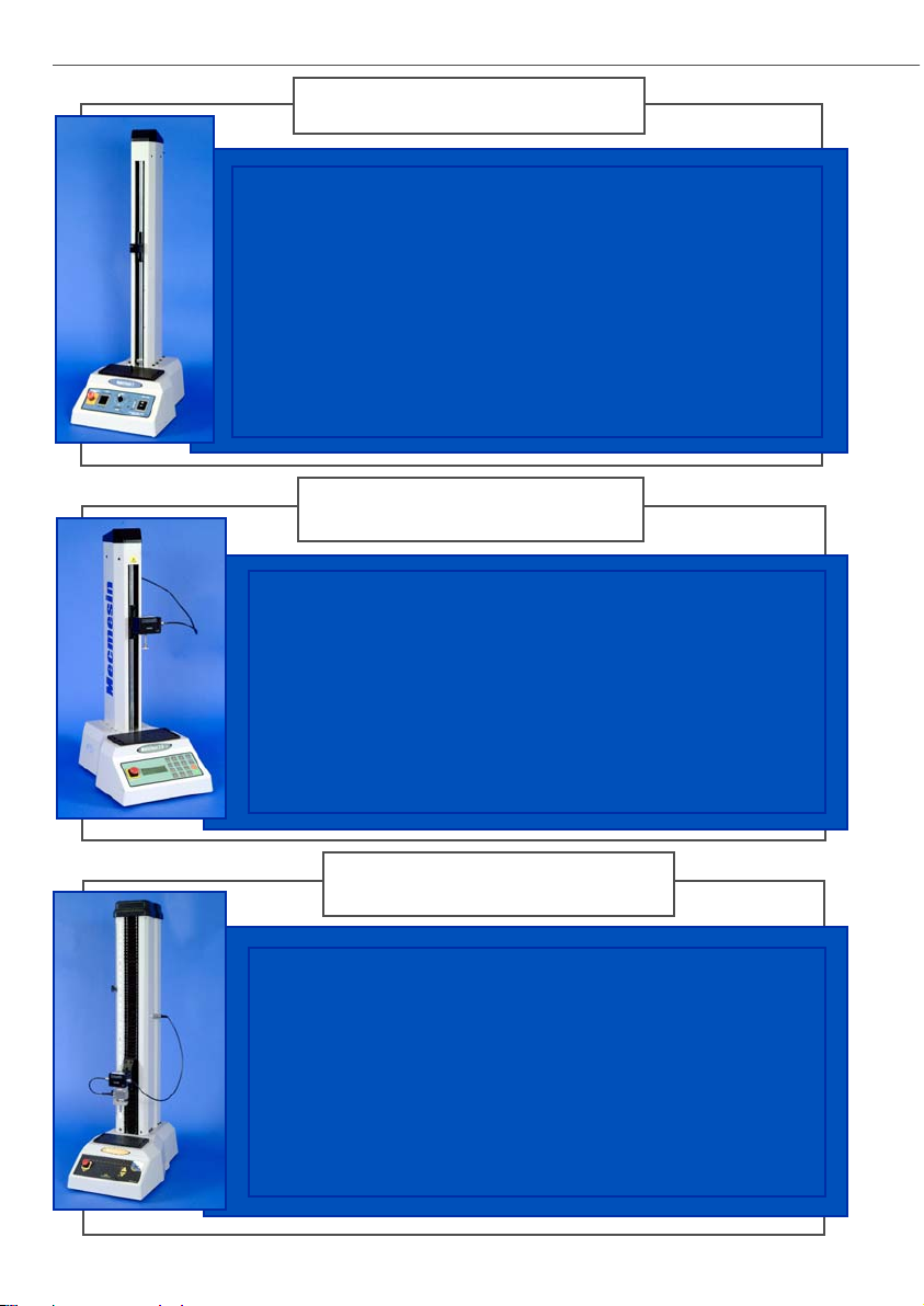
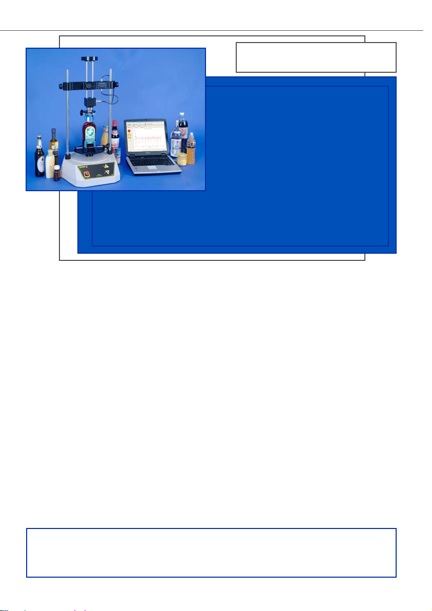
The Vortex-iis a fully computercontrolled motorized torque
testing system. A Vortex
improves reproducibility by
allowing constant speed testing.
However, a Vortex-
i
will enable
complete control of the test
procedure, analysis and reporting by using a new
torque version of Mecmesin Corporation’s powerful,
flexible and user-friendly Emperor software.
Vortex-
i
To view our range of accessories please request our brochure by
calling 703 433 9247 or visit our website and download the brochure
under ‘Literature & FAQ’s’.

45921 Maries Road
Suite 120
Sterling
Virginia 20166
U.S.A.
t: 703-433-9247
f: 703-444-9860
i: www.mecmesin.com
e: usa-sales@mecmesin.com
DISTRIBUTOR STAMP
431-156-V10
 Loading...