

Page 1
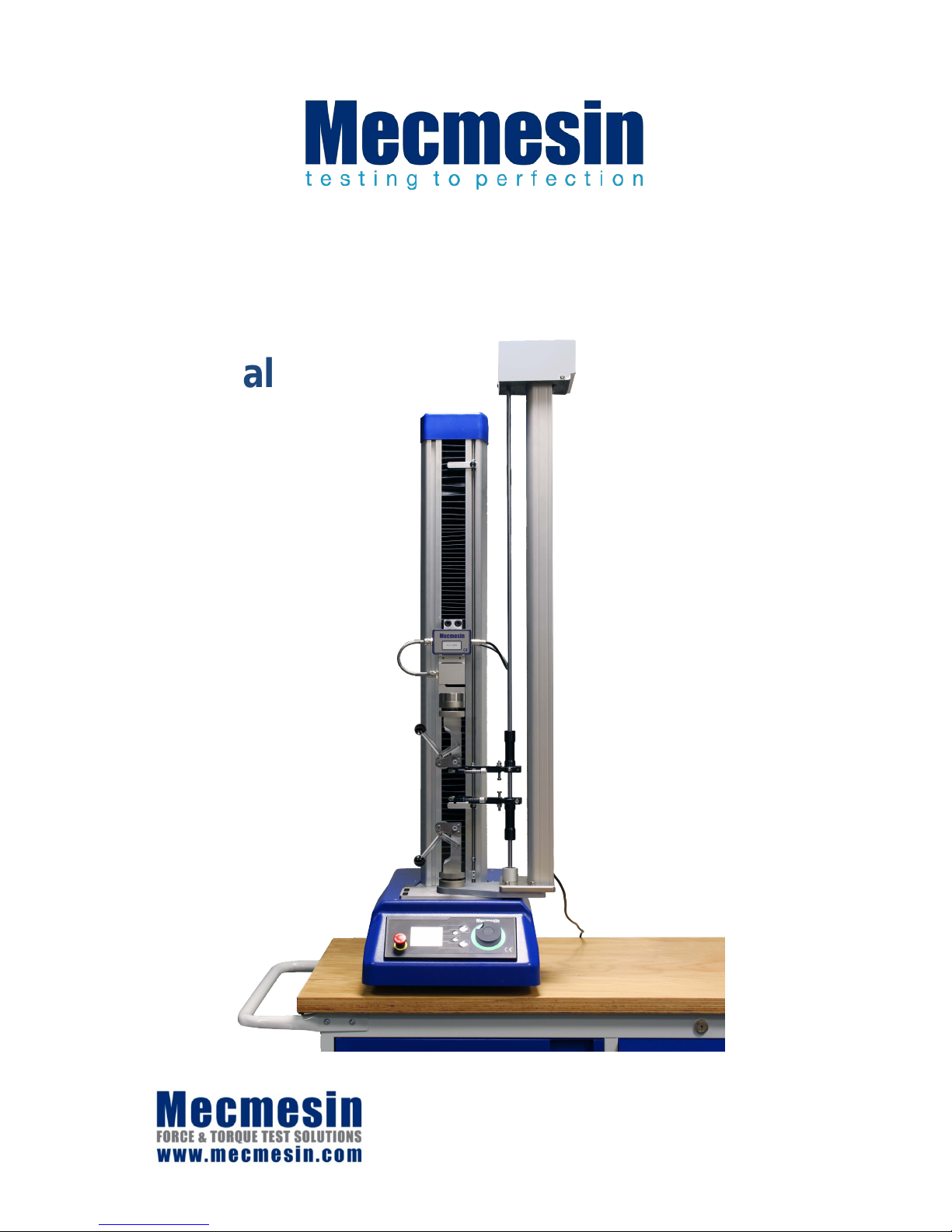
OmniTest™-5.0 Operation
and Installation
Manual
431-959-02
July 2018
Page 2

2 Mecmesin OmniTest-5.0 Operating Manual
The Scope of this Document
This reference manual covers the operation of an OmniTest-5.0 force test stand, intended for
use with Mecmesin enhanced load sensors, extensometer devices and other Mecmesin
accessories. Operation of additional accessories is covered in separate documentation.
The following manuals may aid you in the use of your test stand:
• Guide to Safe Use of Mains Powered Test stands (part no. 431-398),
• VectorPro™ MT for OmniTest and dV Test Stands (part no. 431-955),
• Long Travel Extensometer Installation Guide (part no. 431-957),
Important
It is essential that you familiarise yourself with the contents of this Manual and the separate
Guide to Safe Use of Mains Powered Test stands (part no. 431-398) before attempting to operate
your OmniTest-5.0 Test stand.
20
18 © Mecmesin Ltd, supplied with Mecmesin test stands and not for redistribution
Part no. 431-959-02
Page 3

OmniTest-5.0 Operating Manual Mecmesin 3
Contents
1. Items Supplied with your Test Stand 4
Accessories 4
2. OmniTest-5.0 System Diagram 5
3. Initial Setup 6
3.1 Unpacking the Stand 6
3.2 Lifting the Test Stand 6
3.3 Environment Conditions 6
3.4 Mains Power Supply 7
3.5 Fitting OmniTest-5.0 Foot Clamp 7
3.6 ELS: Enhanced Load Sensor 8
3.7 Fitting an ELS to your Test stand 9
Connecting an ELS to the OmniTest-5.0 10
3.8 Connecting the OmniTest-5.0 to a PC 10
Cable Management 10
3.9 Attaching Grips and Fixtures 11
3.10 Setting the Limit Stops 12
3.11 Test Stand States 12
4. Front Panel Controls 13
Emergency Stop Button 13
Multi-function Scroll Wheel Control 13
OmniTest Display Panel 15
On-Screen Icons 15
5. Automatic ELS Firmware Update 18
Step 1 - Connect Yo ur ELS D evi ce 18
Step 2 – Starting the Upgrade 18
Step 3 – Flashing the Device 19
6. OmniTest™-5.0 Settings 20
Settings: Jog settings 20
Settings: PIN Code 20
Settings: Pre-load Threshold 20
Settings: Information 20
7. Rear Connectors Panel 21
8. OmniTest™-5.0 Specification 22
9. OmniTest™-5.0 Dimensions 23
10. Declaration of Conformity 24
11. Oper ator Notes 25
Page 4
4 Mecmesin OmniTest-5.0 Operating Manual
1. Items Supplied with your Test Stand
When ordering your OmniTest-5.0 test stand you will be supplied with the following parts:
• OmniTest-5.0 test stand,
• Mains cable,
• Document: A Guide to Safe Use of Mecmesin Mains Powered Test stands,
• Document: OmniTest-5.0 Operation and Install Manual,
• OmniTest-5.0 Foot Clamp,
Note: Accompanying VectorPro™ MT software may be supplied either via a physical flash
drive or software download link
Accessories
For a full range of enhanced load sensors (ELS), extensometers and accessories, please go to
the Mecmesin website www.mecmesin.com, or your local distributor, as listed on the back
cover of this document.
• For connection of the stand to your computer system a Mecmesin supplied 2m USB B to
USB A cable communications cable is required (part no. 351-093).
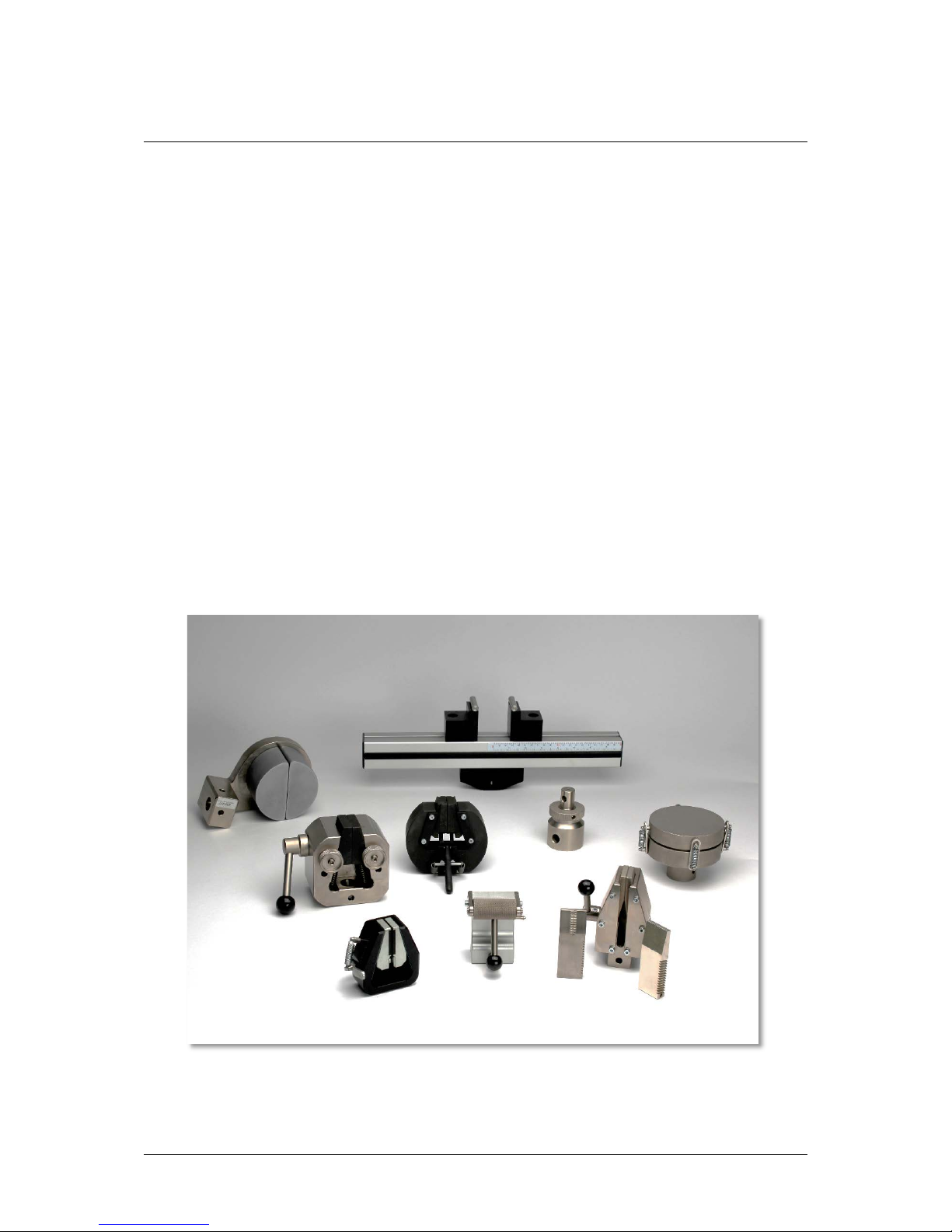
Here you can see some of the grips and fixtures that are available.
Page 5
OmniTest-5.0 Operating Manual Mecmesin 5
2. OmniTest-5.0 System Diagram
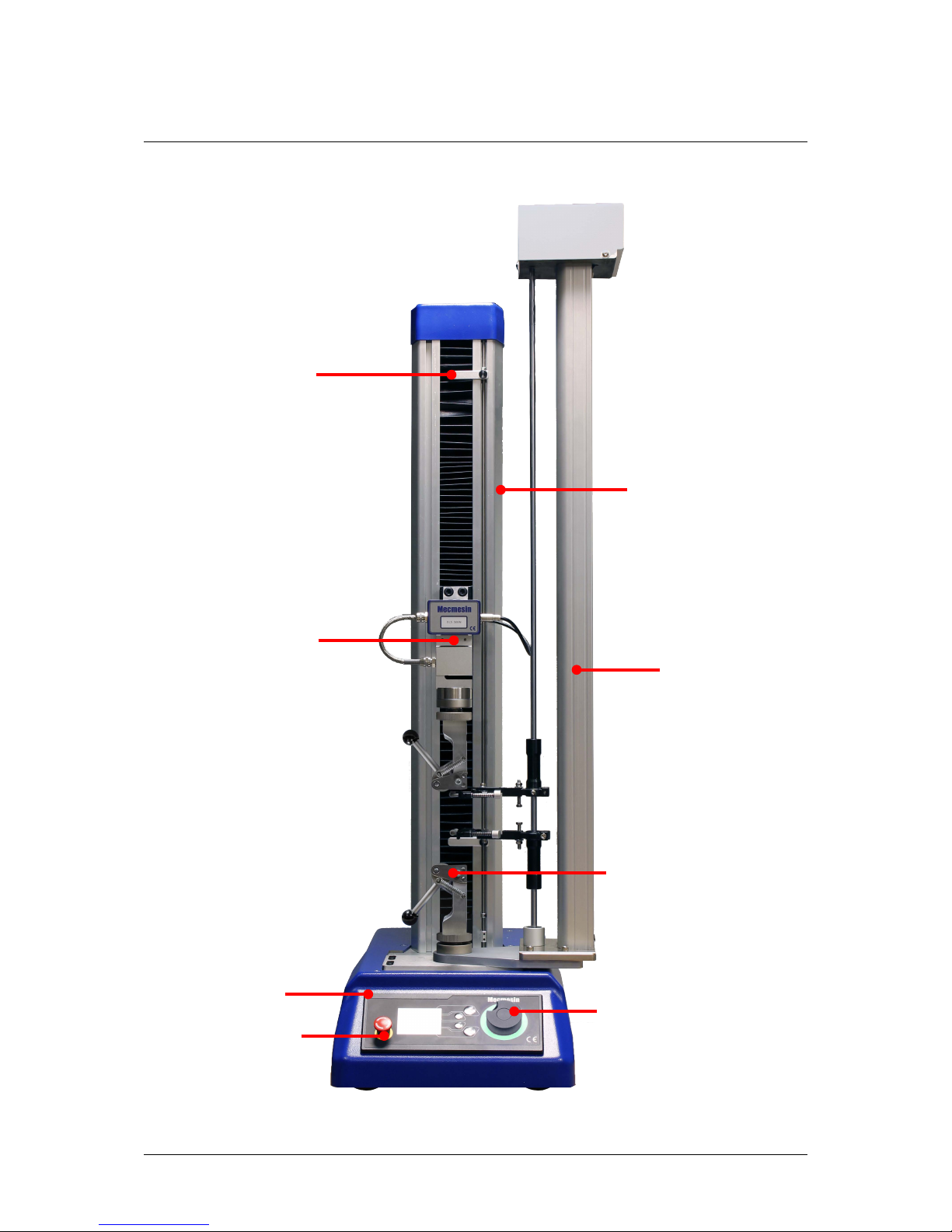
Easily accessible upper and
lower safety limit switches
ELS S
-beam variant
Front control panel
Multi-function scroll
wheel
Emergency stop
Mecmesin LTE-700, long
travel extensometer
(Optional accessory, part
no. 432
-700)
Mecmesin 5kN eccentric
roller grips
(Optional
accessory, part no. Mec7
-5)
T
-slot profile runs down
either side of the main
column, allowing for
mounting of accessories
su
ch as tablet PC’s
Page 6

6 Mecmesin OmniTest-5.0 Operating Manual
3. Initial Setup
3.1 Unpacking the Stand
When you first receive the stand please check that there is no obvious damage to the
packaging. If there is any sign that the packaging or the test stand itself has been damaged,
please contact Mecmesin or your authorised distributor immediately. Do not use the stand
until you have done so.
We strongly recommend that the packaging is retained, as this can be useful if the machine
needs to be returned for calibration or shipped between sites.
Section 1 lists items that should be included with your test stand. Please contact Mecmesin or
your authorised distributor if any items are missing or damaged.
3.2 Lifting the Test Stand
The unpackaged weight of the test stand is given in the specification table at the back of this
manual. Do not try to lift heavy loads unaided. It is advised to use suitable lifting equipment
when moving your OmniTest-5.0 system.
3.3 Environment Conditions
In line with BS EN 61010-1 it is recommended that your Mecmesin OmniTest-5.0 test stand is
operated in an environment that matches the following conditions:
• Indoor use only, recommended to be operated in a lab environment.
• Altitude up to 2 000 m;
• Temperature range between 10 °C to 40 °C. Please note that the instrument should not be
used for long durations at higher temperatures.
• T
he maximum relative humidity is 80 % for temperatures up to 31 °C decreasing linearly
to 50 % at 40 °C. It is crucial that the surrounding environment does not cause water to
form on the device.
• Mains supply voltage fluctuations up to a maximum of ±10 % of the nominal voltage.
• The environments should also take considerations of excessive dust or metal particulates
as ingress of these into the device can cause damage to the system.
Page 7
OmniTest-5.0 Operating Manual Mecmesin 7
3.4 Mains Power Supply
OmniTest-5.0 test stands can be used on 110–120 or 220–240 V ac 50-60 Hz supplies. The rear
fuse carrier will be set for your local requirement but is reversible, so should you replace a
fuse, the correct local voltage must be selected.
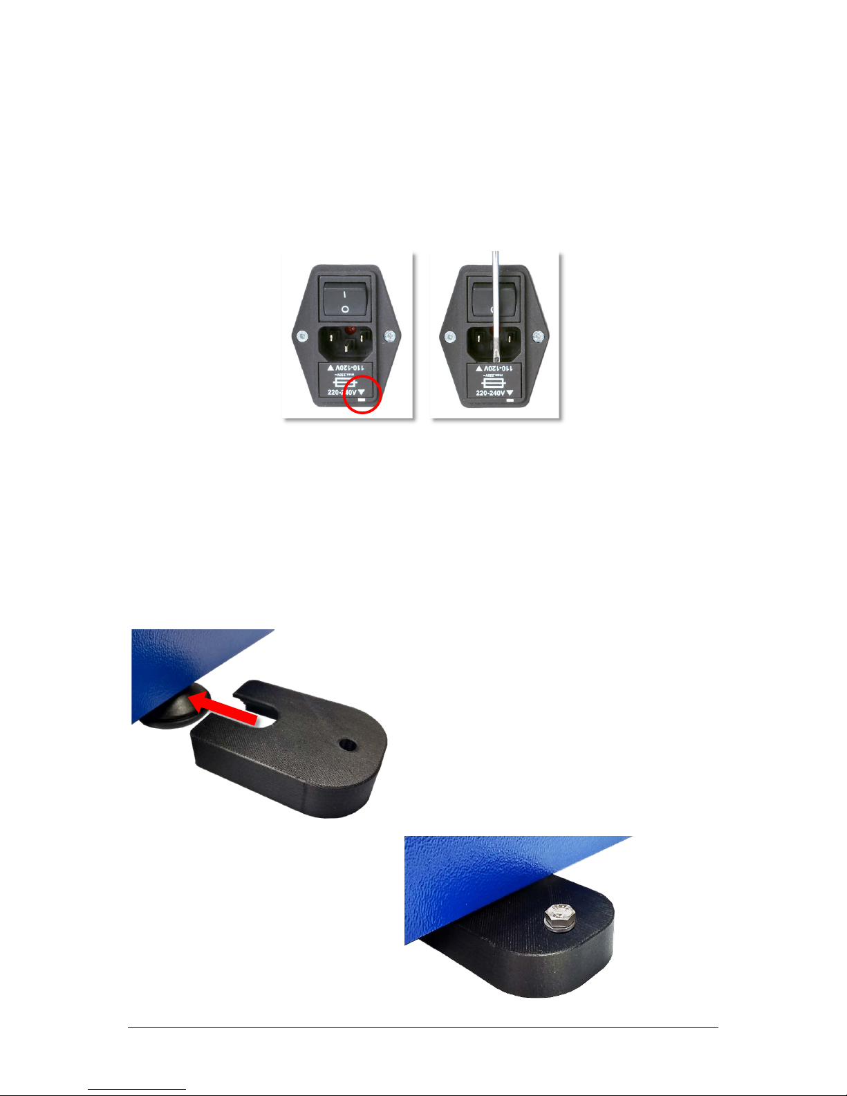
The voltage that is selected is indicated by which arrow is pointing to the white line located
at the bottom of the device. This is illustrated in the image below, shown within the red circle
Removing the fuse holder
3.5 Fitting OmniTest-5.0 Foot Clamp
OmniTest-5.0 test systems are supplied with four foot clamps (Part no. 409-027), these can be
used to secure your test system to a suitable work surface. This prevents the stand from
toppling or sliding. It is recommended that you use the foot clamps, especially for systems
with LTE devices fitted.
To
secure your OmniTest-5.0 first slide the foot
clamp over the feet located on the base of the stand
(pictured right).
T
hen, thread the supplied M6 screw
through the foot clamp and your work
surface. Using the supplied M6 nut and
washer secure the foot clamp below the
work surface.
Note: To secure the foot clamp, 4 x M6
clearance holes will need to be drilled
through the work surface.
Page 8
8 Mecmesin OmniTest-5.0 Operating Manual
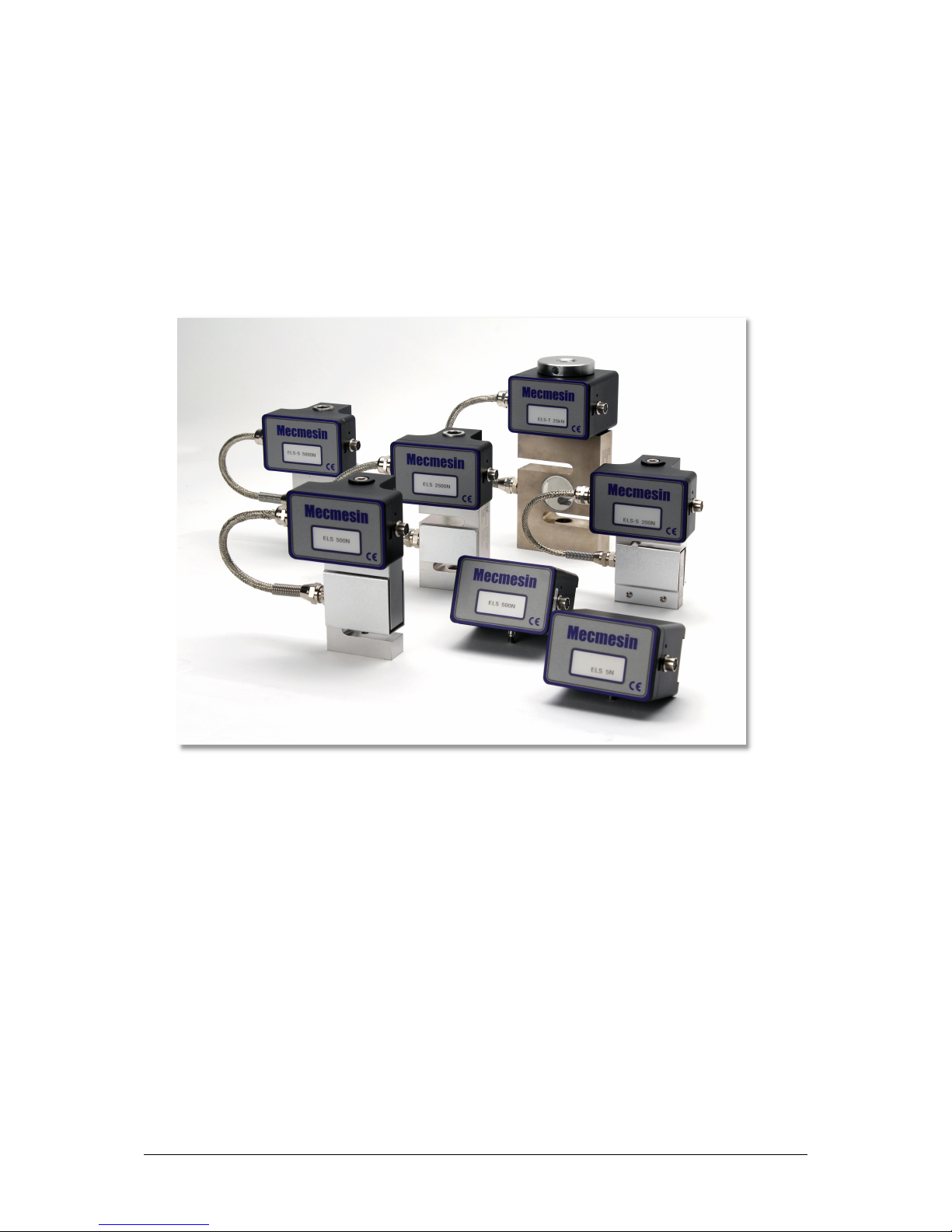
3.6 ELS: Enhanced Load Sensor
Enhanced load sensors or ELS for short, are smart devices used to capture load readings for
OmniTest-5.0 test stands, all calibration information is held on the individual load cell
meaning they can be swapped from system to system and the calibration will follow with no
input required.
These load cells are available in a range of sizes and designs to best suit your requirements.
See the specifications section of this document for details relating to capture rate and accuracy.
A selection of enhanced load sensors (Not all ELS devices shown are compatible with
OmniTest-5.0 test stands)
Page 9
OmniTest-5.0 Operating Manual Mecmesin 9
3.7 Fitting an ELS to your Test stand
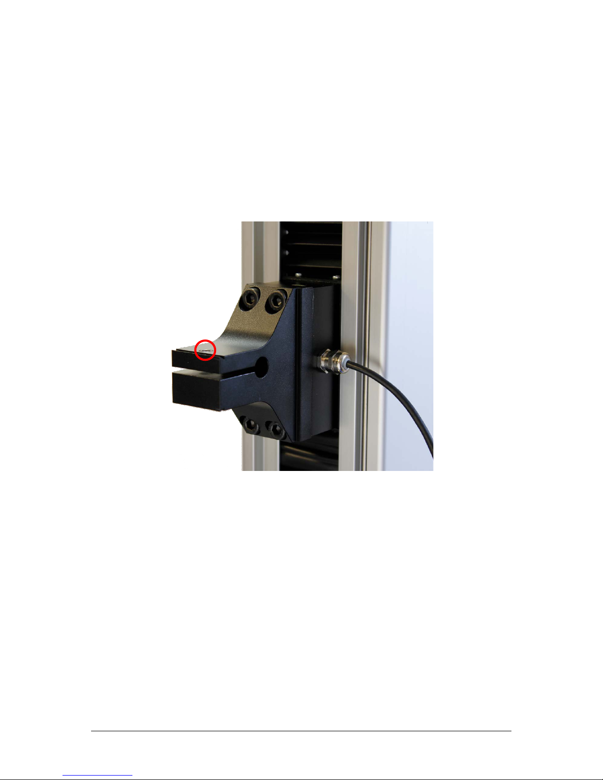
The OmniTest-5.0 has a dovetail bracket attached to the moving crosshead, which tightens by
using an Allen key on the embedded screw.
To fit your ELS to your test stand slide the load cell sideways onto the dovetail and tighten
the grub screw (circled below in red) located in the dovetail using a suitable Allen key.
To prevent damage, do not over-tighten the grub screw in the dovetail when a gauge bracket
is not present.
OmniTest-5.0 Dovetail, note the grub screw circled in red
No
te: Take care when handling low capacity ELSs such as a 5N cell, as damage can easily
occur from mishandling.
It is also important to ensure that attached grips and fixtures do not overload the ELS. If in
doubt please check the weight of any addition grips and fixtures prior to fitting these.
Page 10
10 Mecmesin OmniTest-5.0 Operating Manual
Connecting an ELS to the OmniTest-5.0
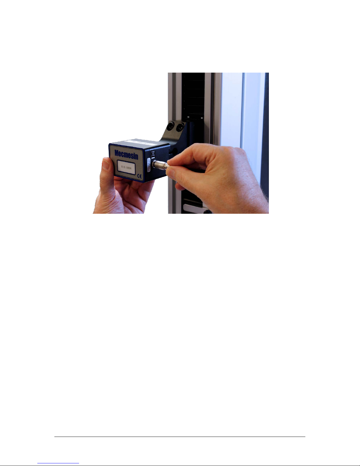
To connect your ELS to your OmniTest stand simply plug the 6-pin connector located on the
machines crosshead into the ELS fitted.
Connecting the 6-pin plug to the ELS
As enhanced load sensors are ‘smart’ devices all calibration and capacity information is
passed to the stand automatically as the sensor is connected.
3.8 Connecting the OmniTest-5.0 to a PC
To connect your OmniTest-5.0 test stand to VectorPro™ MT software, connect the USB B port
to a PC using cable part no. 351-093.
Important! Please install VectorPro™ MT software on your desired PC before connecting the
test stand to your PC.
Cable Management
It is essential that no cables are permitted to interfere with the controls or any moving parts.
Page 11
OmniTest-5.0 Operating Manual Mecmesin 11
3.9 Attaching Grips and Fixtures
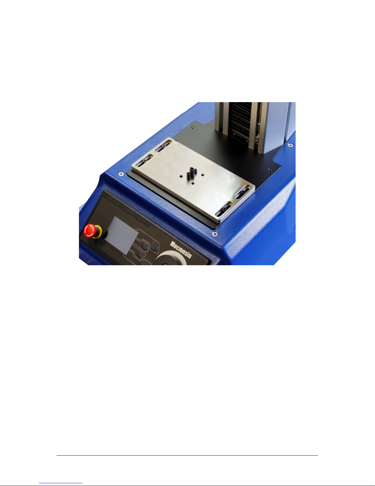
For flexible attachment of a variety of accessories and improved alignment, the OmniTest-5.0
is fitted with an anvil plate to accept fixtures with different screw threads.
This is attached with four bolts using an Allen key. For alignment, the anvil plate can be
loosened, moved forwards or back, and the bolts retightened.
Anvil plate complete located at the base of the OmniTest-5.0
Upper grips and accessories are attached directly to the ELS device being used.
QC adapters are available and can be fitted directly to the anvil plate or through a Mecmesin
LTE-700 extensometer.
Page 12
12 Mecmesin OmniTest-5.0 Operating Manual
3.10 Setting the Limit Stops
Limit stops help prevent damage to load cells and fixtures by stopping the crosshead
movement before the moving fixtures come into contact with static parts of the stand. Their
positions are adjusted after the fitting of fixtures and test samples.
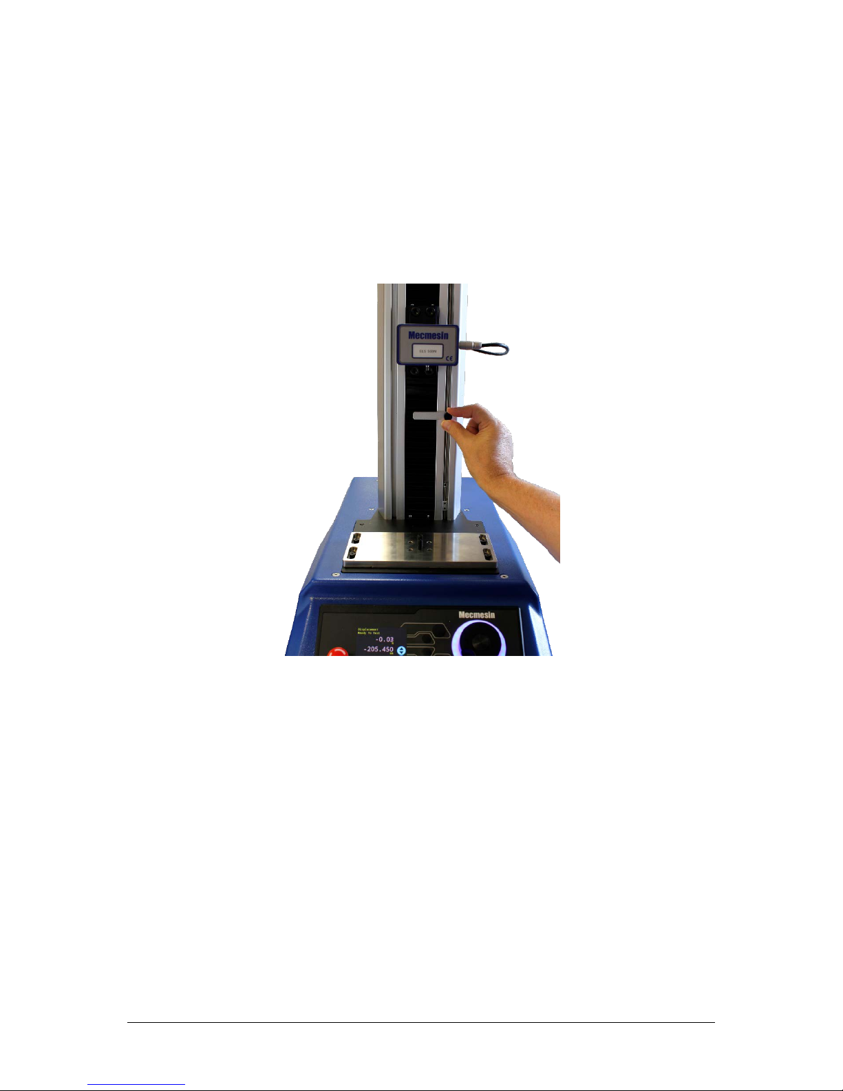
There are two manually-set limit stops, located for your convenience, on the front of the
OmniTest-5.0. These are set by loosening the thumb-screw, moving the stop to a new position
and retightening. When the crosshead meets a stop, it activates a switch. This will stop
crosshead movement at an upper or lower limit.
Limit stops on an OmniTest-5.0
3.11 Test Stand States
The test stand can be in one of five states:
1. Test readiness - ready to start, or complete
,
2. Te
sting – test operation sequence is running,
3. Stopped - test interrupted or emergency stop pressed,
4. Jog mode - for jogging or positioning the crosshead manually,
5. Settings menu – for adjusting your test stands settings,
In each state, the selector buttons have functions described by the on-screen icons.
Page 13
OmniTest-5.0 Operating Manual Mecmesin 13
4. Front Panel Controls
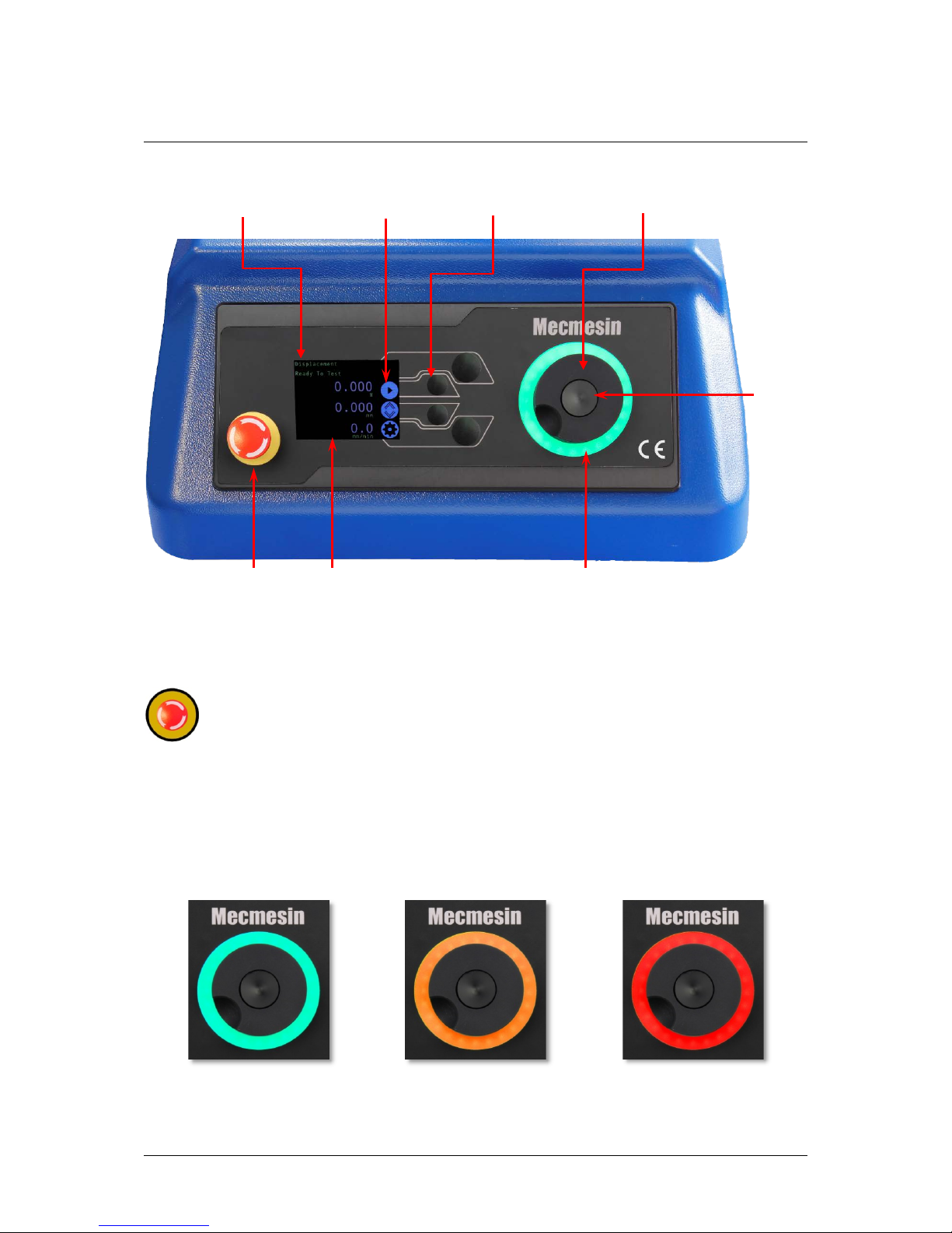
Emergency Stop Button
Push to immediately stop crosshead movement. Rotate the button to release it and
resume crosshead control. If pressed during a test, do not simply restart a test,
ensure you remove any residual force using the test stand’s jog controls.
Multi-function Scroll Wheel Control
Scroll Wheel Colours
The LED light ring surrounding the scroll wheel shows three colours, indicating three states,
these states are:
LED dial
ring
Scroll
wheel
button
Multi-function scroll
wheel
Emergency
stop
Display
Button
functions
Status
messages
Multi-function
selector buttons
Green Light
Pulsating: Ready t o st ar t test
Rotating: Scrolling through a menu
Amber Light
Static: Test completed
Rotating: Crosshead
moving
Red Light
Static: Test stopped/limit
triggered
Page 14
14 Mecmesin OmniTest-5.0 Operating Manual
Jog Mode
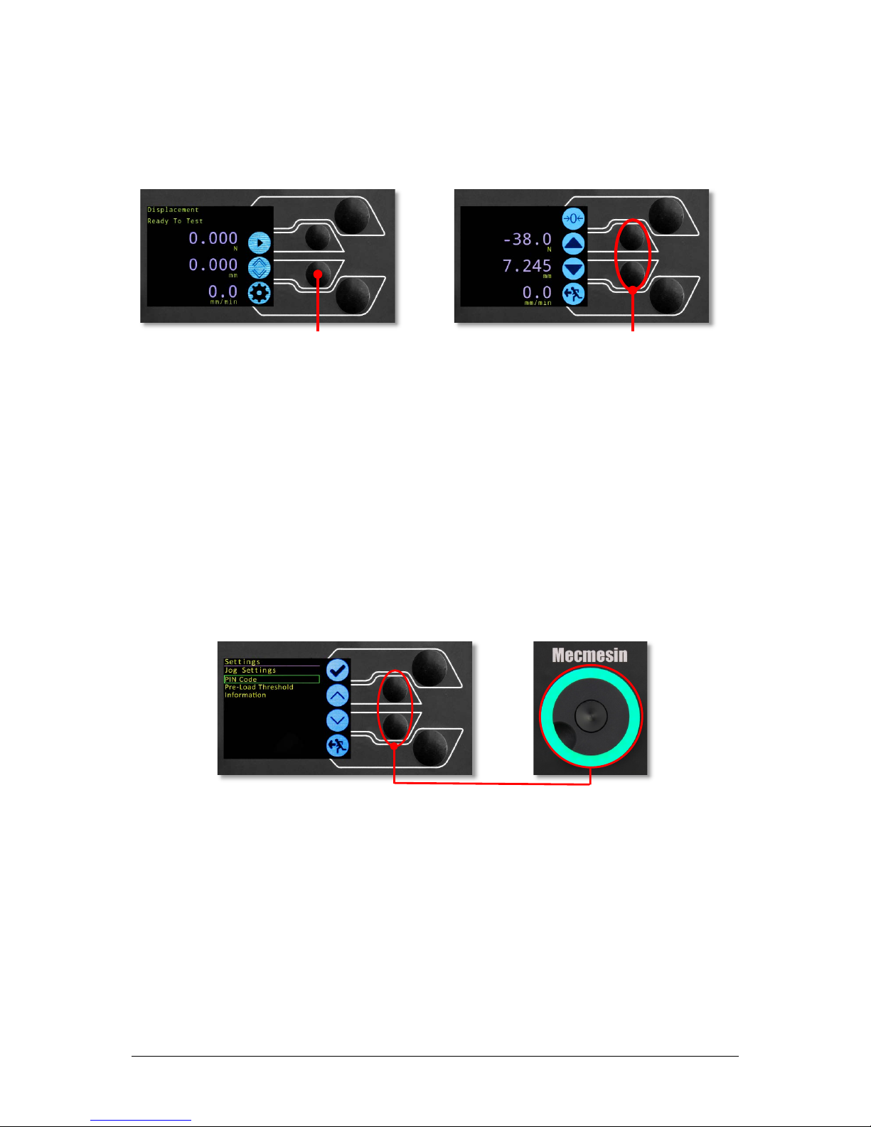
When in jog mode the wheel drives the crosshead directly up (clockwise) or down
(anticlockwise). This offers more variable control when compared to the two fixed speed jog
control buttons (circled in red below).
Th
e scroll wheel can also be used as a speed controller. The jog buttons move the crosshead
at the set speeds (configured in the ‘Jog Settings’ menu picture below), but rotating the wheel
clockwise whilst holding a jog button will increase the speed and rotating the wheel
anticlockwise whilst holding a jog button will decrease the speed.
OmniTest-5.0 test stands also feature a precision jog mode, rotating the scroll wheel while
holding the central scroll wheel button moves the test stand at its minimum speed, this is
useful when fitting specimens into grips for example.
Navigational Control
The scroll wheel can also be used to navigate the menus. When in a selection menu, the scroll
wheel cycles through the selections and their values. This is an alternate navigational option
to using the up and down arrow buttons.
Th
e Button
The central button is used to confirm a menu selection. It is equivalent to the tick button.
It can also be used to activate fine jog control, by rotating the scroll wheel while holding the
central scroll wheel button moves the test stand at its minimum speed.
Enter jog mode
Jog control buttons
Menu: operates with buttons or wheel
Page 15
OmniTest-5.0 Operating Manual Mecmesin 15
OmniTest Display Panel
The display indicates the stand status, displays live values and is used to configure the test
stands settings.
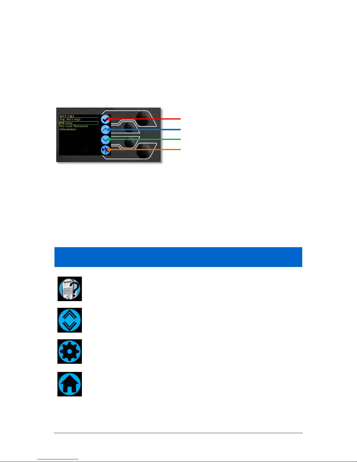
The purpose of the four multi-function button is indicated on screen by an adjacent icon.
Below is an image showing a typical example of the on-screen icons in relation the physical
buttons.
On-Screen Icons
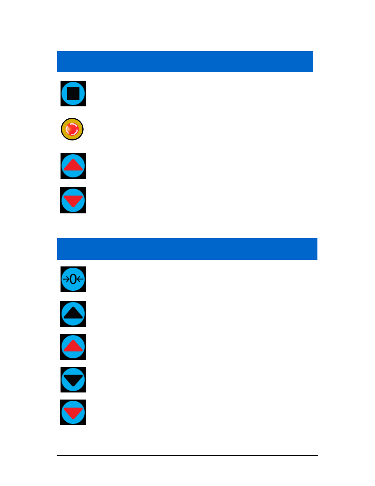
On-screen icons vary depending on the current state of the test stand and what functions the
physical buttons perform at that point. Below is are reference tables to help explain the icon
definitions.
A: Pre-Test
Icon Action
No ELS connected.
Go to jog mode.
Go to settings.
Move to the home position (zero position from the be g in nin g o f the
previous test).
Top button is ‘confirm’
Upper middle button is ‘up’
Lower middle button is ‘down’
Lower button is ‘back’
Page 16
16 Mecmesin OmniTest-5.0 Operating Manual
B: Test Stop
Icon Action
S
top test: This stops crosshe ad movement, leaving the stand in a state
of test readiness. The message is ‘Interrupted: User’ and the test
readiness buttons (A) are displayed as well as the home button.
Emergency stop button pushed: Message: ‘Emergency Stop!!!’. Release
the emergency stop to regain control and remedy the situation before
resuming testing. No te there is no on-screen icon for the emergency
stop.
Upper limit switch trigger ed: The crosshead has reached the upper
travel limit, as set by the OmniTest-5.0’s limit switches, and stopped.
Further travel in this direction is prevented.
L
ower limit switch triggered: The crosshead has reached the lower
travel limit, as set by the OmniTest-5.0’s limit switches, and stopped.
Further travel in this direction is prevented.
C: Jog Mode
Icon Action
Zero (tare) all system values.
Move the crosshead upward at the set jog speed.
Crosshead has reached an upper limit (load signal from a connected
gauge, set to Stop, or a limit switch) and stopped.
Move the crosshead downward at the set jog speed.
Crosshead has reached a lower limit (load signal from a connected
gauge, set to Stop, or a limit switch) and stopped.
Page 17

OmniTest-5.0 Operating Manual Mecmesin 17
D: Settings Menu
Icon Action
Confirm selection (or press the scroll wheel button).
Navigate up a menu selection or value (or turn the wheel clockwise).
Navigate down a menu selection or value (or turn the wheel
anticlockwise).
Go back to the previous screen.
Page 18
18 Mecmesin OmniTest-5.0 Operating Manual
5. Automatic ELS Firmware Update
All OmniTest-5.0 test stands with firmware 3.1.0.0 and above have the ability to update the
firmware of any ELS device. This feature is seamlessly managed through the front panel and
ensures that the latest firmware is on your ELS devices.
Step 1 - Connect Your ELS Device
To start the update connect your ELS to your test system, then switch the test stand on.
N
ote: Analogue short travel extensometers can also be updated in a similar method, simply
plug the extensometer device in to the corresponding connector on the rear of your OmniTest.
Step 2 – Starting the Upgrade
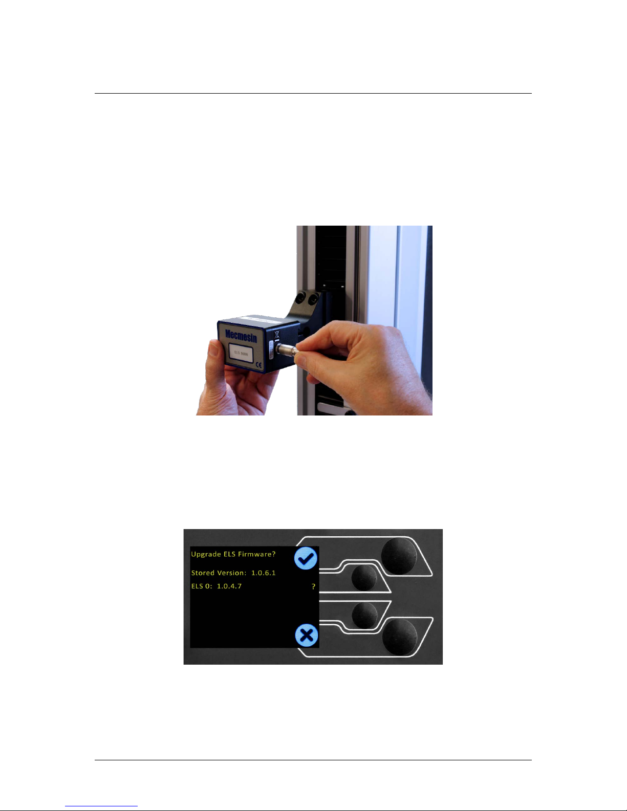
On the display located on the front panel of the test stand you will be presented with the
following screen.
The new ‘Stored’ firmware is listed at the top of the display and the current ELS firmware is
display below. In this instance the ELS current firmware is 1.0.4.7, starting the update will
flash the device to version 1.0.6.1. If more than one ELS is connected (load cell and a short
analogue extensometer) the additional device will be listed below ELS 0. To start the update
of the first ELS device press the ‘tick’ icon.
Page 19
OmniTest-5.0 Operating Manual Mecmesin 19
Step 3 – Flashing the Device
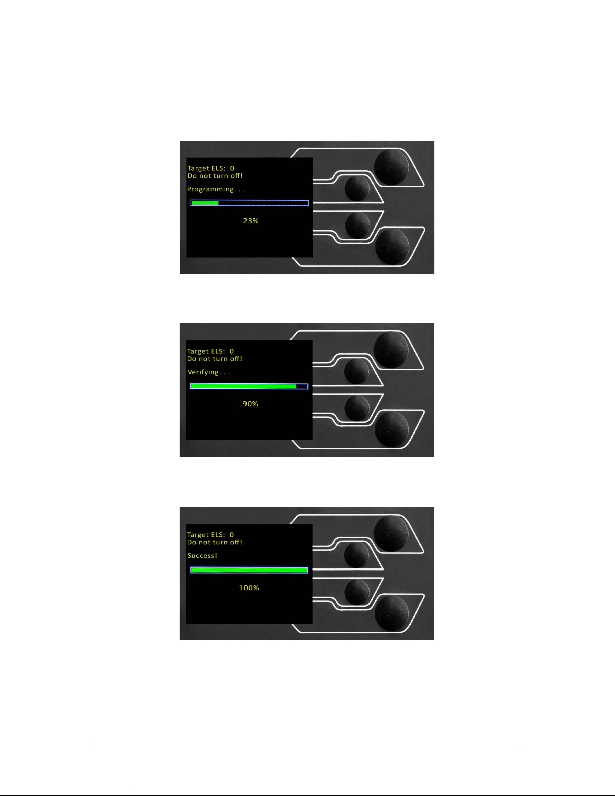
The flashing of the device is carried out automatically and progresses through several stages.
It is important that the test stand is not turned off or disconnected. Disconnection of the ELS
could lead to irreversible damage.
In the image above initial programming is taking place. You can monitor the progress using
the bar and percentage readout below.
Within the final stage of the process the firmware upgrade is verified to check that is has
completed successfully.
Once the process is at 100% the display will indicate that the firmware upgrade has been
successful. You will then either be prompted to update the next ELS device currently connect
or the display will return to the start screen, if no additional ELS devices are connected.
You can check the version of the ELS firmware manually by accessing the ‘Information’ screen
located in the ‘Settings’ menu, See Section 6 for more information.
Page 20

20 Mecmesin OmniTest-5.0 Operating Manual
6. OmniTest™-5.0 Settings
All settings are made by moving the selection marker to the required item or digit and
confirming with the tick button or using the central scroll wheel button.
Settings: Jog settings
Within the jog settings menu, you can configure the jog speed and force limits while in jog
mode. Below is a detailed breakdown of each setting and the options available for each setting.
Setting Action Range
Up Speed
Configure the jog speed in an upward motion
0.050 to 1200
mm/min
0.002 to 47.24
Inch/min
Down Speed
Configure the jog speed in a downward motion
0.050 to 1200
mm/min
0.002 to 47.24
Inch/min
Tension Limit
Configure the tensile force limit for jog operations
Up to 2500N
Up to 562 lbf
Compression Limit
Configure the compressive force l imit for jog operations
Up to 2500N
Up to 562 lbf
Settings: PIN Code
Within the PIN code menu, it is possible to set a four-digit number that can be used to lock
the menu feature of your OmniTest-5.0. Please note once this has been set you cannot access
the menu without the PIN, so it is crucial that you keep a record of this safe. To remove the
PIN code set the four digit number to ‘0000’.
Settings: Pre-load Threshold
This menu displays the pre-load threshold as configured by VectorPro™ MT, changes here
will be overwritten by VectorPro next time you start a test.
Settings: Information
This screen is used to display key information relating to your OmniTest-5.0 and connected
ELS. Here you can see software, hardware and firmware properties as well as the calibration
date for the test stand and the number of overloads that have occurred for the current ELS.
Page 21
OmniTest-5.0 Operating Manual Mecmesin 21
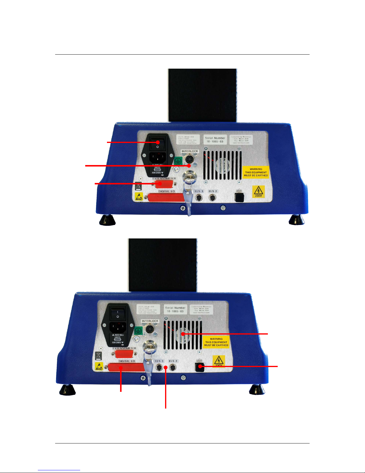
7. Rear Connectors Panel
Extensometer
port
Interlock
port and
override key
Inlet mains filter
and on/off switch
Digital IO port
(Not currently implemented)
Additional ELS ports
USB-B Comms
port
System fan. Do
not obstruct!
Page 22

22 Mecmesin OmniTest-5.0 Operating Manual
8. OmniTest™-5.0 Specification
* Measured without fixtures ** Measured on centreline of load sensor
Connectivity
USB port, extensometer input, 3 x low voltage additional sensor inputs with future
ex pan sio n capab ility
PC requirements
(recommended)
Int el Core i5 p ro cess or , 8GB R A M , one US B 2.0 or 3.0 por t , S SD hard drive w it h 10GB fr ee
space, scree n resolu t ion 1920x1080 full HD
P C requirements (minimum)
Intel/AMD dual core processor with 2 GHz or faster clock speed, 4 GB RAM, one USB 2.0 or
3.0 po rt, hard drive wit h 10 GB fr ee s pace , s cre en r esolutio n 1080x720
Compatible O S: Windows 7 or Win dows 10 (32 or 64 bit)
Recommended OS: Windows 10 Pro 64 bit
Data o utpu t Yo u can exp or t as P DF, X L S X, CSV , T X T , Email and image file s
Software and communicati o ns
Ope rating system (OS)
kN 5
kgf 500
lbf 1100
1
Class 0.5, according to the requirements of BS EN ISO7500 (requires
optional on-site UKAS accredited system calibration)
Maximum s ampling r ate 500Hz
650mm (25. 6”)
1 µm
±0.1% of indicated position or ±10 microns, whichever is greatest
mm/min 0.05 to 1200
in/min 0.002 to 47.2
0.001 mm/min (0. 00004 In/min)
±0.1% or ±20 microns/min of indicated speed (at steady state)
whichever is greatest
1089mm (42. 9”)
330mm (13”)
570mm (22. 4”)
700mm (27. 6”)
Std. 100mm (3. 9”)
Min/Max 75 mm (2. 95")/200 mm (7.8")
61.2kg (135 lbs)
230V AC 50Hz or 110V AC 60Hz
150 watts
±0.5% of reading down to 5% of range
>1:25000 filtered from 24 bit
20 kHz
10oC to 40
o
C
30%-80% (non-condensing)
Syste m accuracy
Resolution
OmniTest-5kN
Rated capacity kN
Nu mb e r o f ballscrews
Displacement
Crosshead travel*
Operating relative humidity
Environment spec ification
Operating temperature
Accuracy
Accuracy
Maximum power requirement
Enha nced Load Sensors ( ELS)
Sensor measu re ment accuracy
Sensor m easurement resolution
Internal sam pling rate
Voltag e
Speed
Speed range
Speed resol ution
Dimensions
Height
Elec trical supply
Width
Depth
Vertical daylight*
Throat depth**
Weight
Page 23
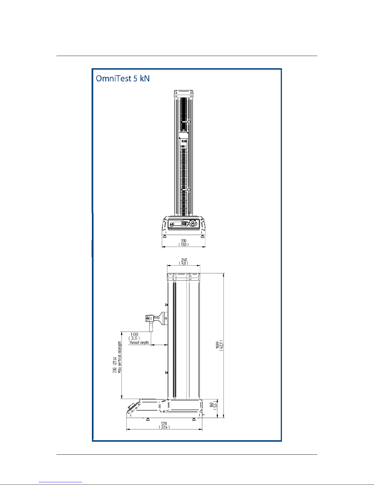
OmniTest-5.0 Operating Manual Mecmesin 23
9. OmniTest™-5.0 Dimensions
Page 24

24 Mecmesin OmniTest-5.0 Operating Manual
10. Declaration of Conformity
Page 25

OmniTest-5.0 Operating Manual Mecmesin 25
11. Operator Notes
Page 26

26 Mecmesin OmniTest-5.0 Operating Manual
Page 27

OmniTest-5.0 Operating Manual Mecmesin 27
Page 28

Mecmesin : a world leader in affordable force and torque testing solutions
Since 1977, Mecmesin has assisted thousands of companies achieve enhanced quality control in design and
production. The Mecmesin brand represents excellence in accuracy, build, service, and value. In production centres
and research labs worldwide, designers, engineers, operators, and quality managers endorse Mecmesin force and
torque testing systems for their high performance across countless applications.
www.mecmesin.com
Algeria
Argentina
Australia
Austria
Bangladesh
Belgium
Brazil
Bulgaria
Cambodia
Canada
Chile
China
Colombia
Costa Rica
Croatia
Czech Republic
Denmark
Ecuador
Egypt
Estonia
Finland
France
Germany
Greece
Hungary
India
Indonesia
Iran
Ireland
Israel
Italy
Japan
Korea South
Kosovo
Kuwait
Laos
Latvia
Lebanon
Lithuania
Macedonia
Malaysia
Mexico
Morocco
Myanmar (Burma)
Netherlands
New Zealand
Norway
Paraguay
Peru
Philippines
Poland
Portugal
Romania
Russia
Saudi Arabia
Serbia
Singapore
Slovakia
Slovenia
South Africa
Spain
Sri Lanka
Sweden
Switzerland
Syria
Taiwan
Thailand
Tunisia
Turkey
UK
UnitedArab Emirates
Uruguay
USA
Vietnam
The Mecmesin global distribution network guarantees your testing solution is rapidly deliver ed and
efficiently serviced, wherever you are.
Head Office – UK
Mecmesin Limited
w: www.mecmesin.com
e: [email protected]
France
Mecmesin France
w
: www.mecmesin.fr
e: contact@mecmesin .fr
Germany
Mecmesin GmbH
w: www.mecmesin.de
e: [email protected]
North America
Mecmesin
Corporation
w: www.mecmesincorp.com
e: [email protected]
Asia
Mecmesin Asia Co. Ltd
w: www.mecmesinasi a.com
e: [email protected]
China
Mecmesin (Shanghai) Pte Ltd
w: www.mecmesin.cn
e: [email protected]
 Loading...