

Page 1
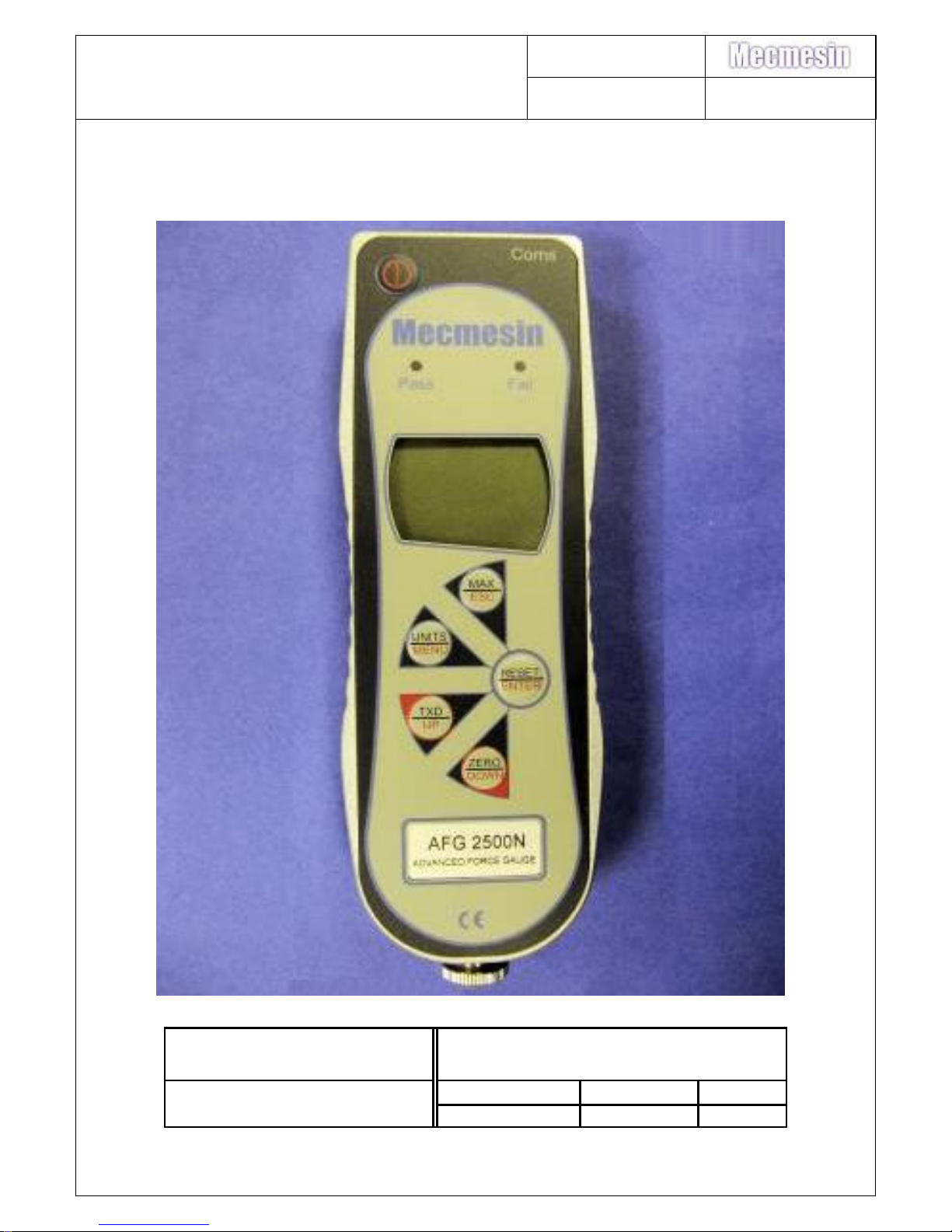
AFG/AFTI Mk 4
Service and Repair Manual
Number 022-614
Issue Number: 09
Page 1 of 47
PDF copy stored in approved
location by: (click on signature for
validation)
Paper copy printed from approved PDF source
by:
Name
Signature
Date
Page 2
AFG/AFTI Mk 4
Service and Repair Manual
Number 022-614
Issue Number: 09
Page 2 of 47
PDF copy stored in approved
location by: (click on signature for
validation)
Paper copy printed from approved PDF source
by:
Name
Signature
Date
1. Contents
1. Contents .............................................................................................................. 2
2. Change History .................................................................................................... 3
3. Product variants .................................................................................................. 4
4. Warnings and cautions: - ..................................................................................... 5
5. Latest software version: - V1.12 .......................................................................... 5
6. Inspection procedure ........................................................................................... 6
7. Notes about 300-157-V03 ................................................................................... 8
8. PCB replacement (300-157-V02/3) ..................................................................... 9
9. Sounder replacement (328-005) ........................................................................ 12
10. Display replacement (301-028-V01) ............................................................... 13
11. Configuration of display 301-028 V1.06 – V1.10 ............................................. 14
12. Configuration of Display 301-028-V01 (V1.12) ............................................... 19
13. Charging socket replacement (329-355) ......................................................... 22
14. Keypad Membrane/Front Cover Plate replacement ........................................ 23
15. Load cell removal ............................................................................................ 24
16. Load cell stud fitting. ....................................................................................... 25
17. Load cell refitting ............................................................................................. 27
18. Battery lid/insulator replacement ..................................................................... 27
19. Firmware version – Identification. ................................................................... 28
20. Firmware release notes .................................................................................. 28
21. PCB Conversion - AFTI to or AFG or Tornado or Orbis .................................. 34
22. Latency ........................................................................................................... 35
23. Display contrast setting. .................................................................................. 36
24. AFG & AFTI Analogue Output. ....................................................................... 37
25. Fault finding. ................................................................................................... 39
26. Spare parts list ................................................................................................ 41
27. Assemblies and parts from China ................................................................... 42
28. Exploded parts diagram .................................................................................. 44
29. Changes to 300-157-V03 ................................................................................ 46
Page 3
AFG/AFTI Mk 4
Service and Repair Manual
Number 022-614
Issue Number: 09
Page 3 of 47
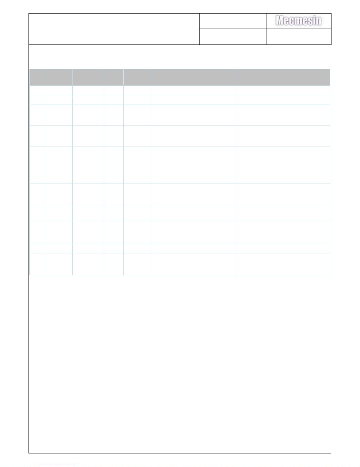
2. Change History
Iss.
Date
Effective
S.No.
DCR
No.
Author
Document / clarification
Change
Mechanical Change
01
04-09-07
Service
Initial issue (020)
02
17-04-09
TF
Prefix 022 & V1.07
03
05-11-09
TF
V1.09, software release, Contrast
setting, Latency & Analogue
sections added.
04
08-02-10
1661
TF
V1.10, 1000N / 2500N Pinned load
cells, Bad 8515 version error
message.
05
25-08-11
1847
1876
TF
mV offset pins to use, 1000N
Pinned load cell removal
V1.12
Config 301-028-V01 LCD
Load cell stud removal
06
26-10-12
2038
TF
LCD behaves unusually.
LCD Config 3179, 3178. EEPROM
Code 9876
06A
-S01 removed from 400-175 & 400-
034
07
23/03/15
2318
TC
Product variants added. Subassemblies added.
Add digital/analogue output info
08
24/06/15
2416
SL
09
04/04/17
2748
GG
PED Open Issue 10068 - Update
service manual change history table to
include Sno. & Mechanical change
columns – Page 20 PNo. updated
Page 4
AFG/AFTI Mk 4
Service and Repair Manual
Number 022-614
Issue Number: 09
Page 4 of 47
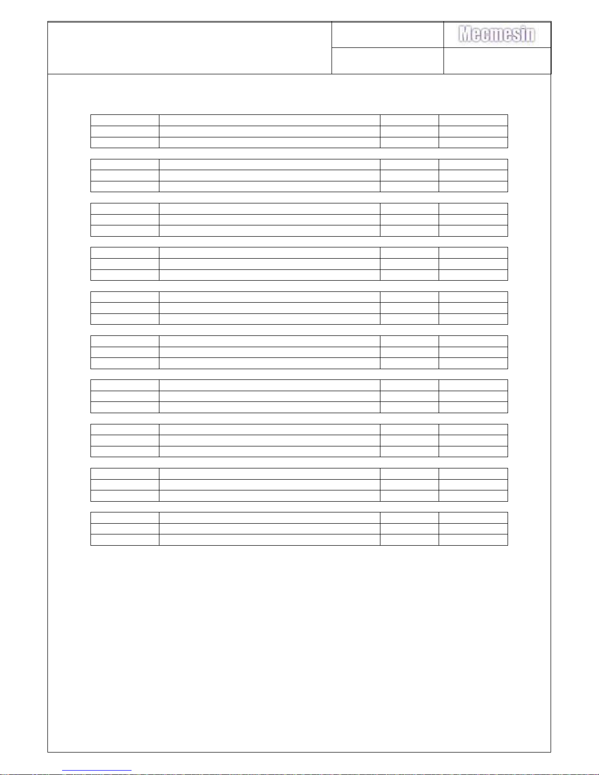
3. Product variants
850-412
Description
Capacity
Output
850-412
AFG 2.5N
2.5N
Digital
850-412-BA
AFG MK4 2.5N + CAL ANALOGUE
2.5N
Analogue
850-413
Description
Capacity
Output
850-413
AFG 5N
5N
Digital
850-413-BA
AFG MK4 5N + CAL ANALOGUE
5N
Analogue
850-414
Description
Capacity
Output
850-414
AFG 10N
10N
Digital
850-414-BA
AFG MK4 10N + CAL ANALOGUE
10N
Analogue
850-415
Description
Capacity
Output
850-415
AFG 25N
25N
Digital
850-415-BA
AFG MK4 25N + CAL ANALOGUE
25N
Analogue
850-416
Description
Capacity
Output
850-416
AFG 50N
50N
Digital
850-416-BA
AFG MK4 50N + CAL ANALOGUE
50N
Analogue
850-417
Description
Capacity
Output
850-417
AFG 100N
100N
Digital
850-417-BA
AFG MK4 100N + CAL ANALOGUE
100N
Analogue
850-418
Description
Capacity
Output
850-418
AFG 250N
250N
Digital
850-418-BA
AFG MK4 250N + CAL ANALOGUE
250N
Analogue
850-419
Description
Capacity
Output
850-419
AFG 500N
500N
Digital
850-419-BA
AFG MK4 500N + CAL ANALOGUE
500N
Analogue
850-420
Description
Capacity
Output
850-420
AFG 1000N
1000N
Digital
850-420-BA
AFG MK4 1000N + CAL ANALOGUE
1000N
Analogue
850-421
Description
Capacity
Output
850-421
AFG 2500N
2500N
Digital
850-421-BA
AFG MK4 2500N + CAL ANALOGUE
2500N
Analogue
Page 5
AFG/AFTI Mk 4
Service and Repair Manual
Number 022-614
Issue Number: 09
Page 5 of 47
4. Warnings and cautions: -
NEVER DISCONNECT THE LOAD CELL FROM THE PCB WITH THE POWER
"ON"
NEVER REMOVE THE BATTERIES FROM THE PCB WITH THE POWER "ON"
IF APPLICABLE, CORRESPONDENCE FROM THE CUSTOMER SHOULD BE
READ BEFORE EXECUTING ANY FORM OF TEST
Antistatic procedures are to be used throughout this work instruction and at all times
when handling populated printed circuit boards (PCBs). Refer to Mecmesin
Procedure 010-016 (Mecmesin internal document).
This manual describes the inspection procedure, where specific keys will need to be
pressed to enter certain modes of the software. Words typed in bold and italic
represent the keys on the keypad, i.e. ENTER or UNITS.
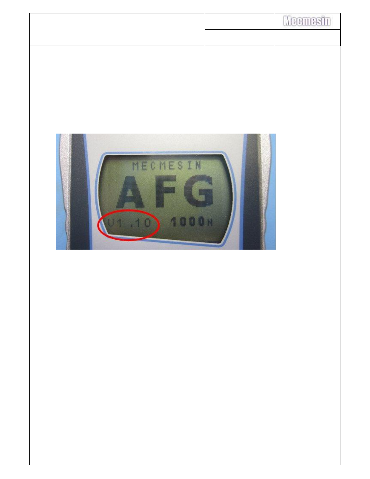
5. Latest software version: - V1.12
The version of software is displayed on the gauge start-up screen (bottom left-hand
corner).
Mecmesin Limited recommends that instruments have the latest version of
software installed.
AFG/AFTI software can be upgraded to the latest version (see section 18 for
software history) using the following:
020-332: AFG4/ORBIS2/TORNADO2 Gauge Serial Programming Work
Instruction.
840-210: Programming kit for gauges.
PLEASE NOTE: - When you have completed the reprogramming of the AFG,
Mecmesin Limited recommends verification of the product to confirm correct
instrument operation.
Note: Correct reprogramming of the unit will NOT affect the Calibration data.
Page 6
AFG/AFTI Mk 4
Service and Repair Manual
Number 022-614
Issue Number: 09
Page 6 of 47
6. Inspection procedure
1) Visually inspect the instrument case, display and communication port for damage.
2) The front label and serial number label should be legible and free from damage.
3) Attach a long extension rod, checking the load cell stud thread is not damaged.
The long extension rod should protrude perpendicularly from the load cell (check
with jig ref. no: 115-001 Mecmesin internal fixture).
4) Turn the instrument on. The audible alarm should sound and the visual alarm
LED’s should light whilst the on key is depressed
5) Check the operation of each key
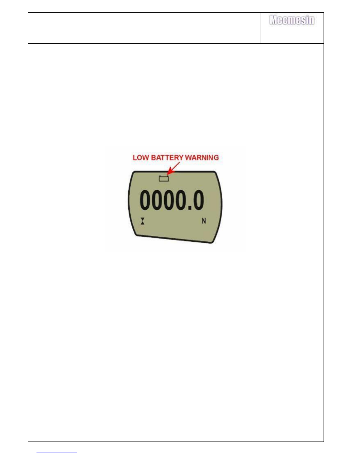
6) Do not inspect the gauge with the “low battery” symbol showing (see below)
If the low battery symbol is showing, either:
Replace the batteries.
Check the existing batteries are not alkaline type and use the mains
adaptor/battery charger.
If alkaline batteries are fitted, fit a serviceable set or remove them and use the
mains adaptor/battery charger.
7) Check the loadcell offset: Software pre V1.01
The Calibration menu displays a password menu and allows the user to check for
load cell offset if overload is suspected.
Lay the gauge on its back without any accessories attached on a flat level
surface.
With the gauge switched on, hold down the MENU key until the menu appears.
Press then MENU key again to go to page two. By using the UP or DOWN keys
select the CALIBRATION option. Press ENTER to select and the display will
show 0000. Press the ENTER key four times (to enter 0000 as the password). A
screen showing the % difference between the critical zero and current reading will
Page 7
AFG/AFTI Mk 4
Service and Repair Manual
Number 022-614
Issue Number: 09
Page 7 of 47
appear. This can be used as an indication of overload and the current condition of
the loadcell.
Press the ESC key twice to revert to normal display.
8) Check the loadcell offset: Software post V1.01
Place the gauge horizontally on a flat level surface. With the gauge switched on, hold
down the MENU key until the menu appears. Press the MENU key again to show
menu page 2. Using up/down buttons select “CALIBRATION” and press ENTER
key. The display will show 0000. Press ENTER four times (to enter 0000 as the
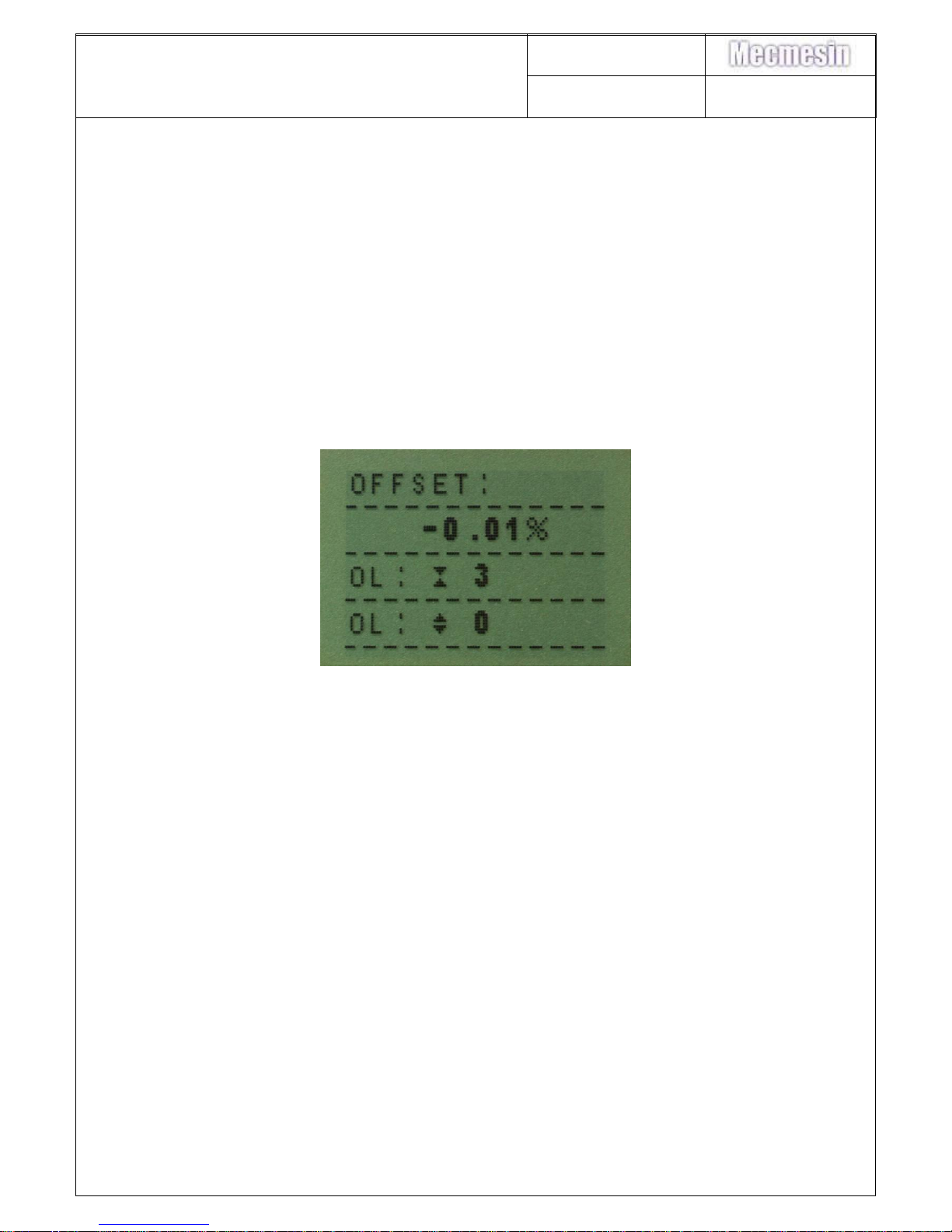
password), a screen displaying the current offset of the load cell as a percentage,
and any overloads in tension and compression.
Press ESC twice to revert to normal display
If the displayed offset is between 5 and 10%, recalibration is recommended.
If the displayed offset is greater than 10%, a replacement loadcell may be required.
These values are given as an indication only – the need for calibration/repair may
vary according to the individual characteristics of the sensor.
To check the load cell mV offset:
Access the load cell connection with the PCB by removing the front case. Section 6
instructions 1 – 7, do not unplug the front panel from the PCB.
With both halves of the gauge connected and the gauge switched on, measure the
load cell excitation voltage between pins 1 and 4, this should be 5V. Then measure
the load cells return signal between pins 2 & 3 (ideally this should read 0.0 mV.)
Once a reading on the voltmeter has been obtained, apply a small force to the load
cell in both directions and ensure the voltmeter display alters in both directions.
Care must be taken whilst applying any force to the load cell,
Page 8
AFG/AFTI Mk 4
Service and Repair Manual
Number 022-614
Issue Number: 09
Page 8 of 47
the gauge display is to be disregarded as the reading may not be accurate.
At zero load there should be a zero mV output from the load cell.
Most load cells can be adjusted to the manufacturer's original specification with upto
a +/-0.8 mV.d.c. offset in either direction. If the offset is greater than +/-0.8 mV. d.c.
hysteresis or failure to display full scale deflection will transpire and the load cell will
have to be replaced.
The direction of the offset can be determined.
i.e. If the volt meter whilst testing without any load being applied to the cell displays
- 0.4 mV d.c. and a compressive force is applied to the cell and the reading
increase's, it can be said that the load cell has suffered a 0.4 mV d.c. overload in
compression.
If the volt meter reading decrease's when the compressive force is applied, the
gauge has an overload in tension.
7. Notes about 300-157-V03
Sensitivity of analogue gauges deemed too difficult to achieve calibration accuracy. A
note from Engineering as below:
“The designed values of the pots used in the AFG with analogue output are such that
adjustment is extremely coarse in relation to the desired tolerance. Engineering do
not consider the design to be fit for purpose and hence it is pot luck (no pun
intended) if the adjustment lands in the correct area. Coupled with variations in the
load cell sensitivity between tension and compression, this makes adjusting the
analogue output of an AFG very time consuming and sometimes impossible.
… Our best short term benefit will be gained from changing the value of the gain pot
and one resistor across the zero pot. This will allow finer adjustment but not
compensate for poor load cell performance.
Due to the coarse-ness of the gain pot, vibration may well have an adverse affect on
calibration.”
300-157-V03 –
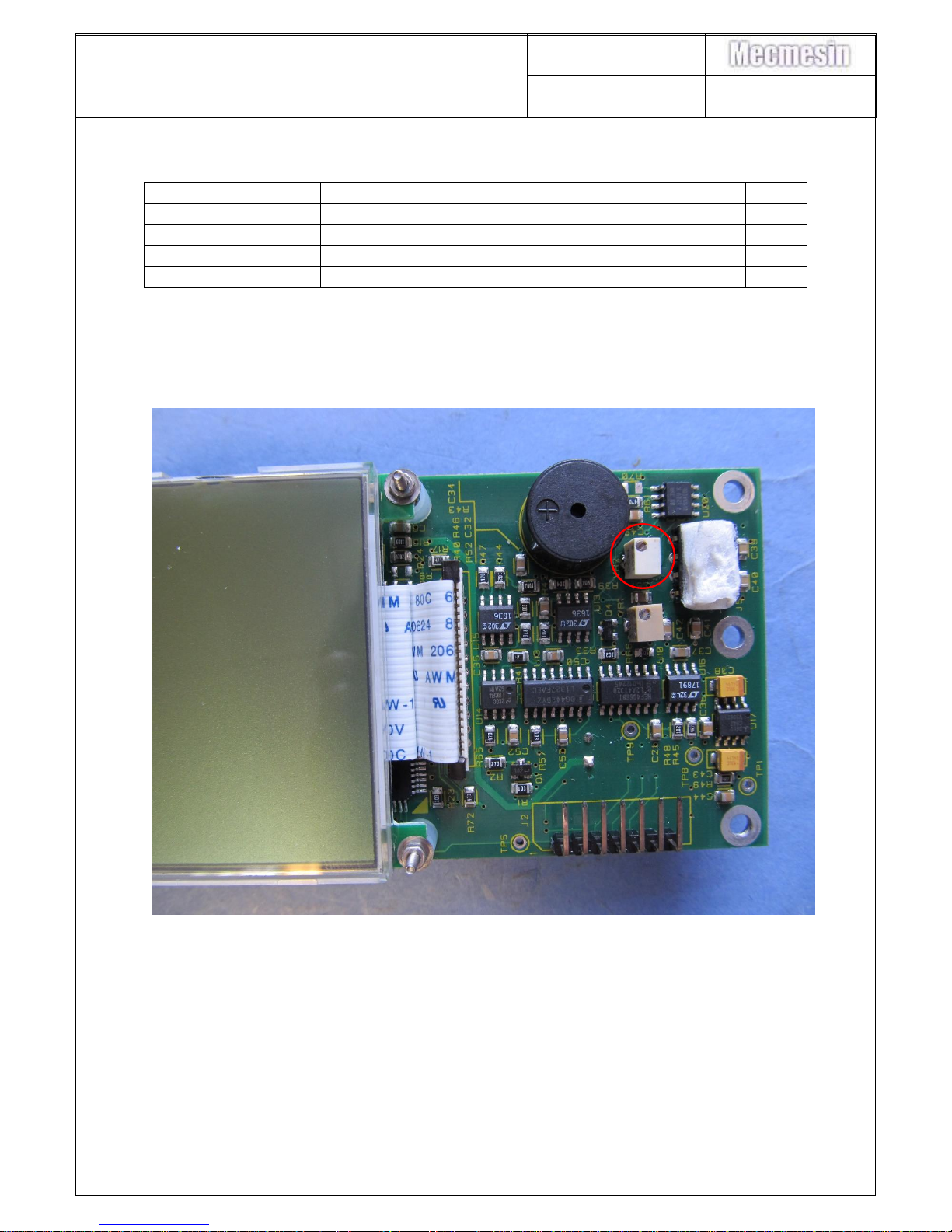
VR2 – replace 315-503 with 315-505
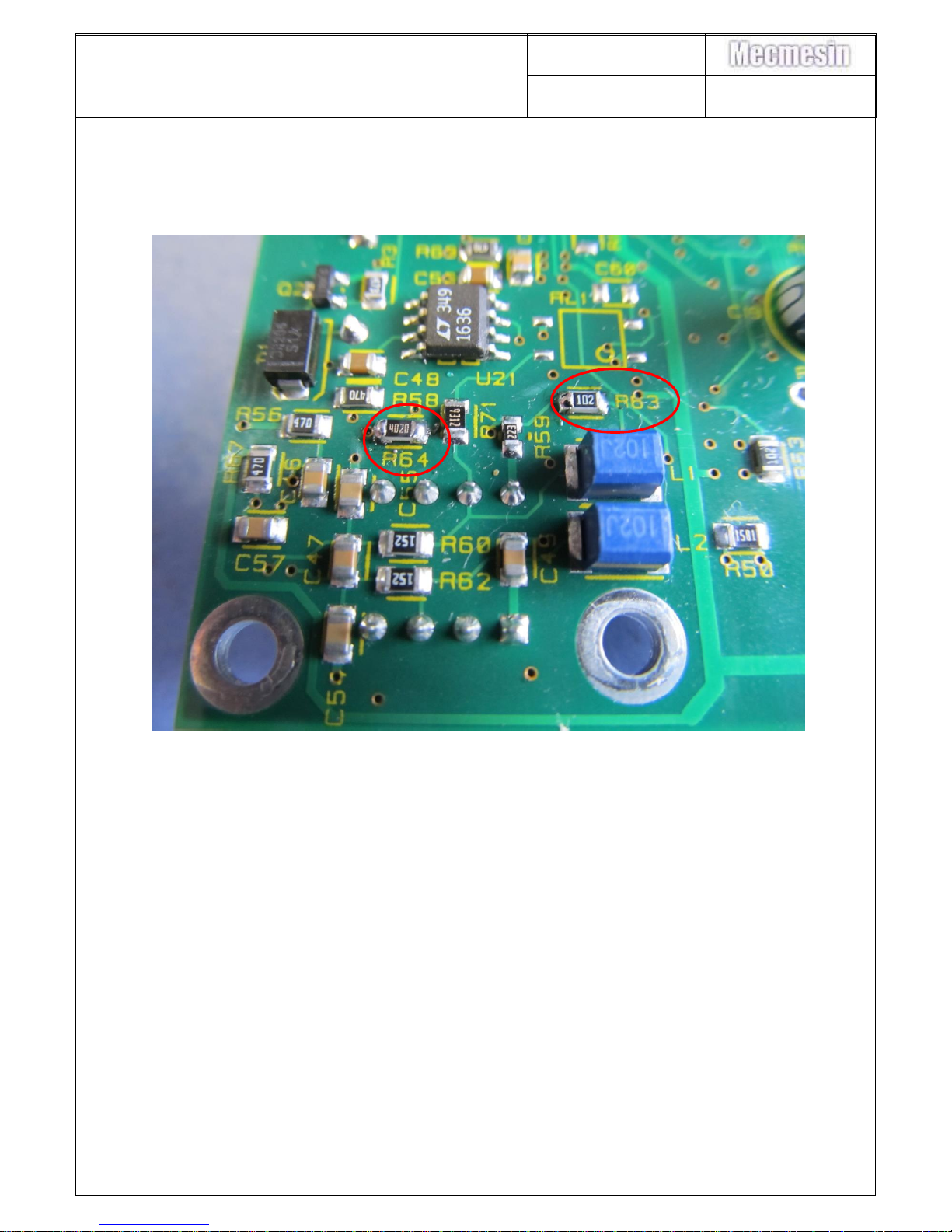
R63 – replace 311-207 with 311-104
R64 – replace 311-180 with 311-012
See section 29 for details of the component changes.
Page 9
AFG/AFTI Mk 4
Service and Repair Manual
Number 022-614
Issue Number: 09
Page 9 of 47
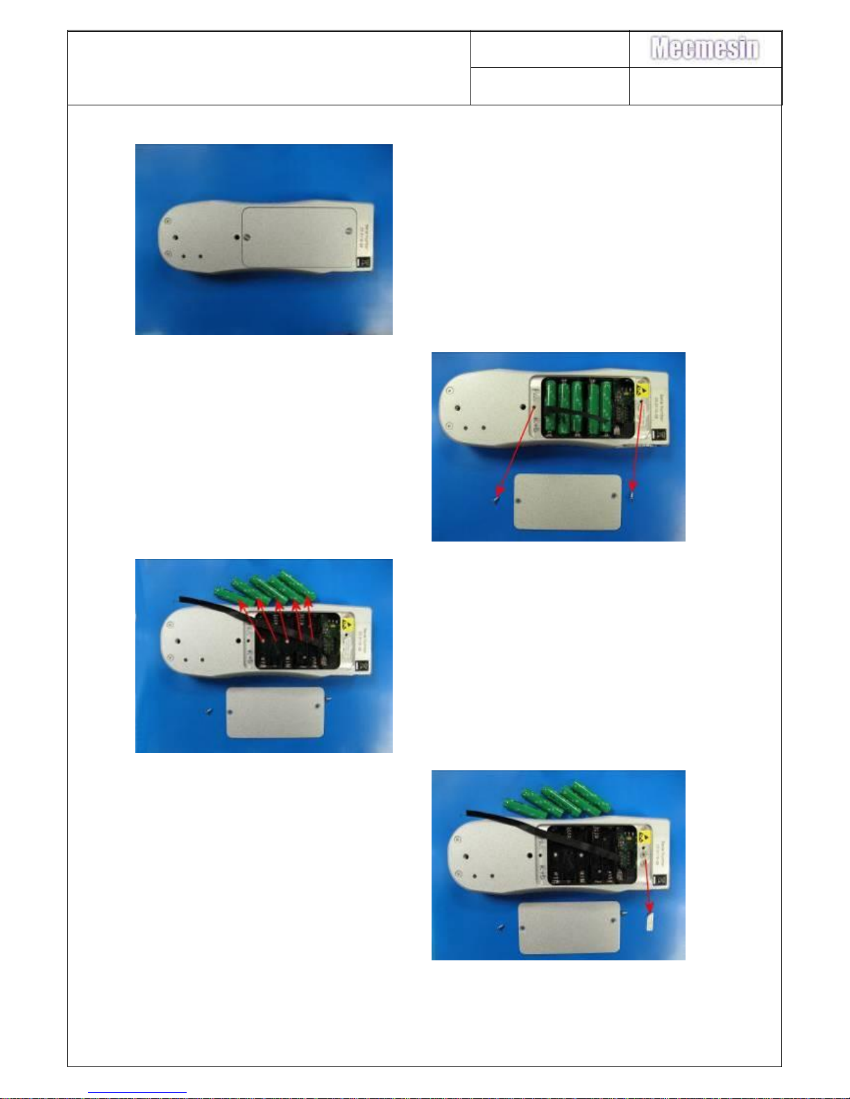
8. PCB replacement (300-157-V02/3)
1. Rear view of AFG/AFTI
2. Remove 2-off M3x6 csk slot
machine screws (420-296)
retaining the battery cover.
3. Remove 5-off batteries.
4. Remove “Guarantee void” label.
Page 10
AFG/AFTI Mk 4
Service and Repair Manual
Number 022-614
Issue Number: 09
Page 10 of 47
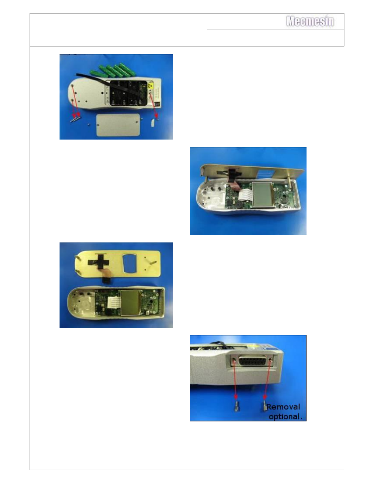
5. Remove 1-off M3x6 pozi csk
stainless steel screw (420-357)
and 2-off M3x20 pozi csk zinc
screws (420-378) retaining the
front panel.
6. Lift off front panel
7. Unplug front panel from PCB
8. Remove 2-off stand-offs from Dtype female connector. (Removal
of the stand-off on the right-hand
side of the photograph is optional).
Page 11
AFG/AFTI Mk 4
Service and Repair Manual
Number 022-614
Issue Number: 09
Page 11 of 47
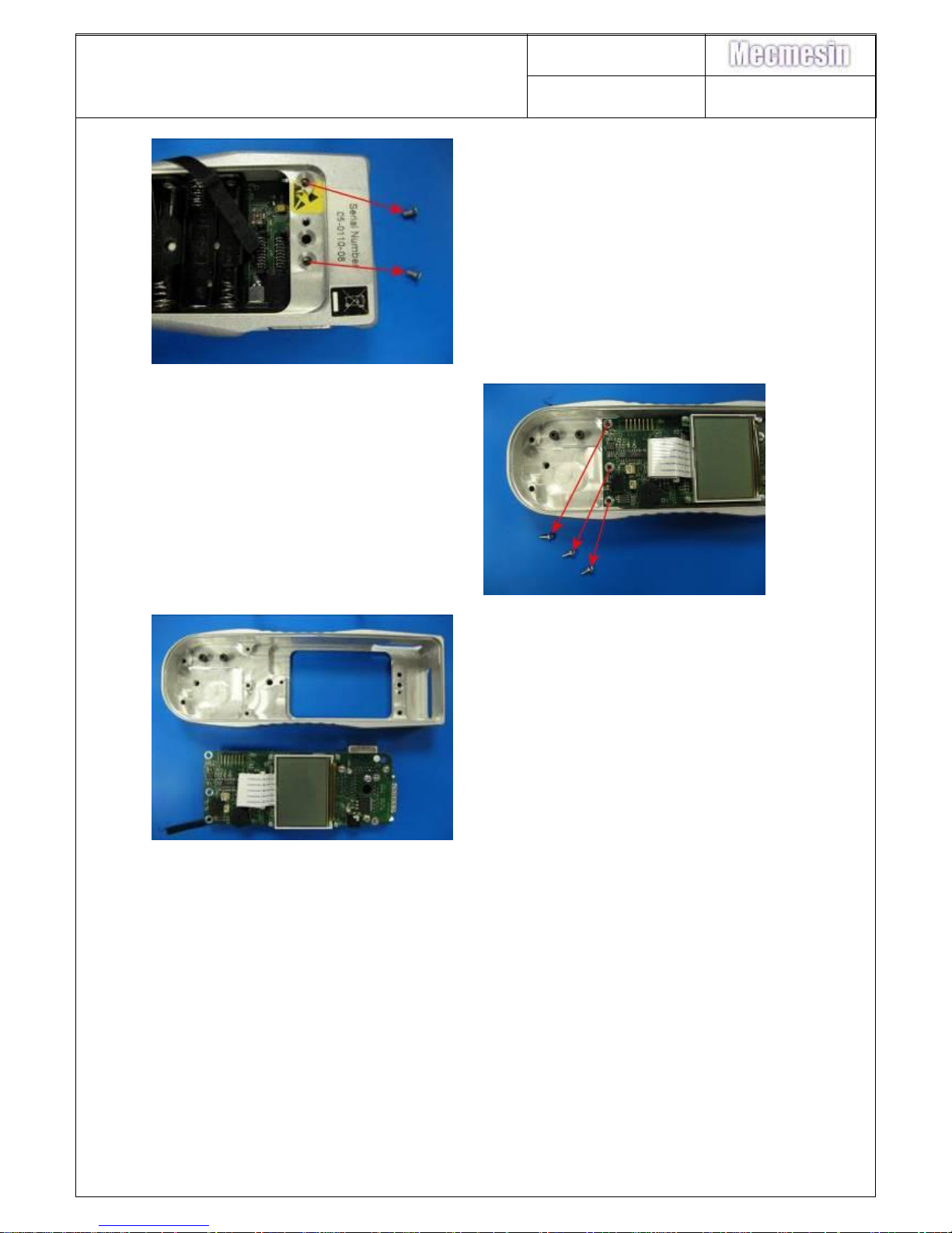
9. Peel back the ESD warning label
and remove 2-off M3x6 csk
stainless steel screws (420-357)
fixing hex spacers to case
10. Remove 3-off M3x6 pan head
taptite screws fixing PCB to casing
11. Lift out PCB (300-157-V01)
Reassembly is the reverse of the above procedure
Page 12
AFG/AFTI Mk 4
Service and Repair Manual
Number 022-614
Issue Number: 09
Page 12 of 47
9. Sounder replacement (328-005)
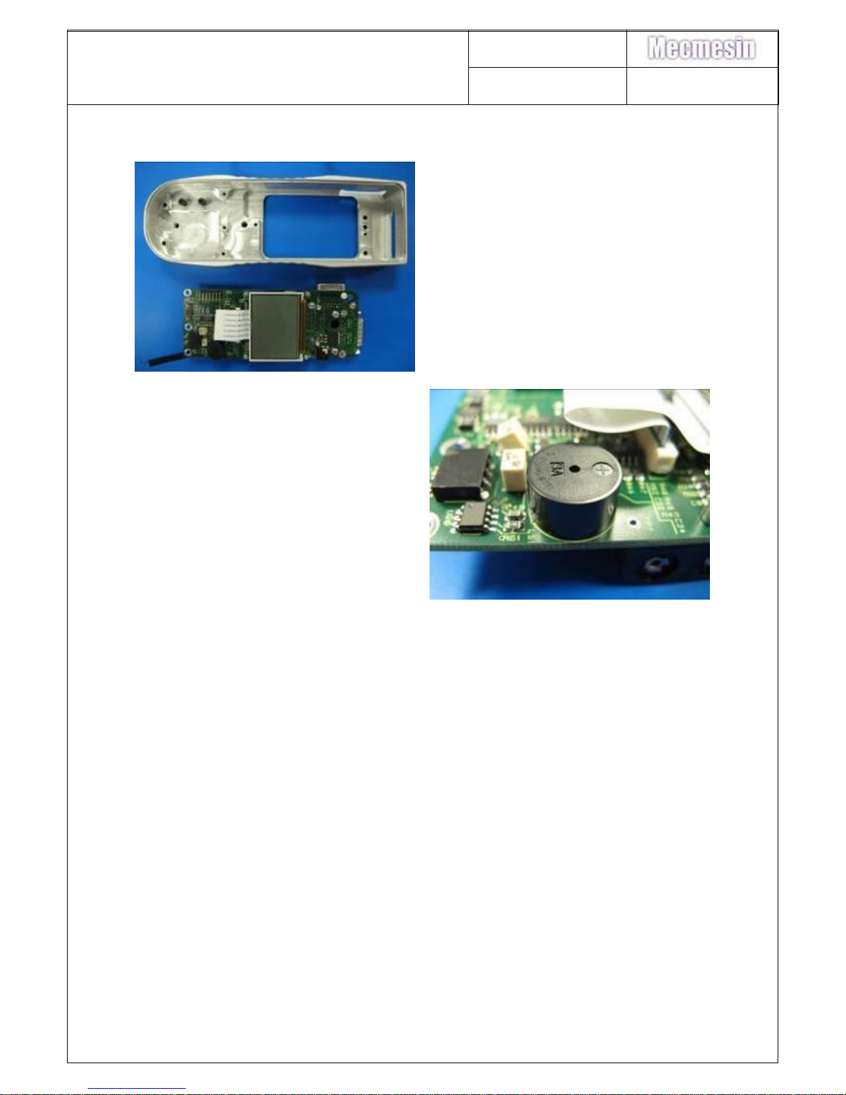
12. Remove PCB as per instructions 1
to 11 in section 6.
13. De-solder the sounder from the
PCB and replace, observing the
correct polarity. The positive
(longer) pin should be inserted
through the hole with a square
solder pad. After soldering, trim off
the excess sounder pins
14. Remove the sticker from the
sounder
15. Test the Sounder. Turn the instrument on. The audible alarm should sound.
Reassembly is the reverse of the above procedure
Page 13
AFG/AFTI Mk 4
Service and Repair Manual
Number 022-614
Issue Number: 09
Page 13 of 47
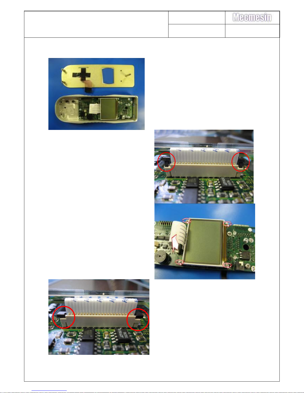
10. Display replacement (301-028-V01)
16. Remove Front Panel as per
instructions 1 to 7 in section 6.
17. Open the LCD ribbon cable
retaining clips located at end of the
header by lifting them up, and
remove the ribbon cable from the
header.
18. Remove the 4-off nuts retaining the
display to the PCB. Remove and
replace the display.
19. Insert the ribbon cable into the
header and secure by pushing the
clips back down.
Page 14
AFG/AFTI Mk 4
Service and Repair Manual
Number 022-614
Issue Number: 09
Page 14 of 47
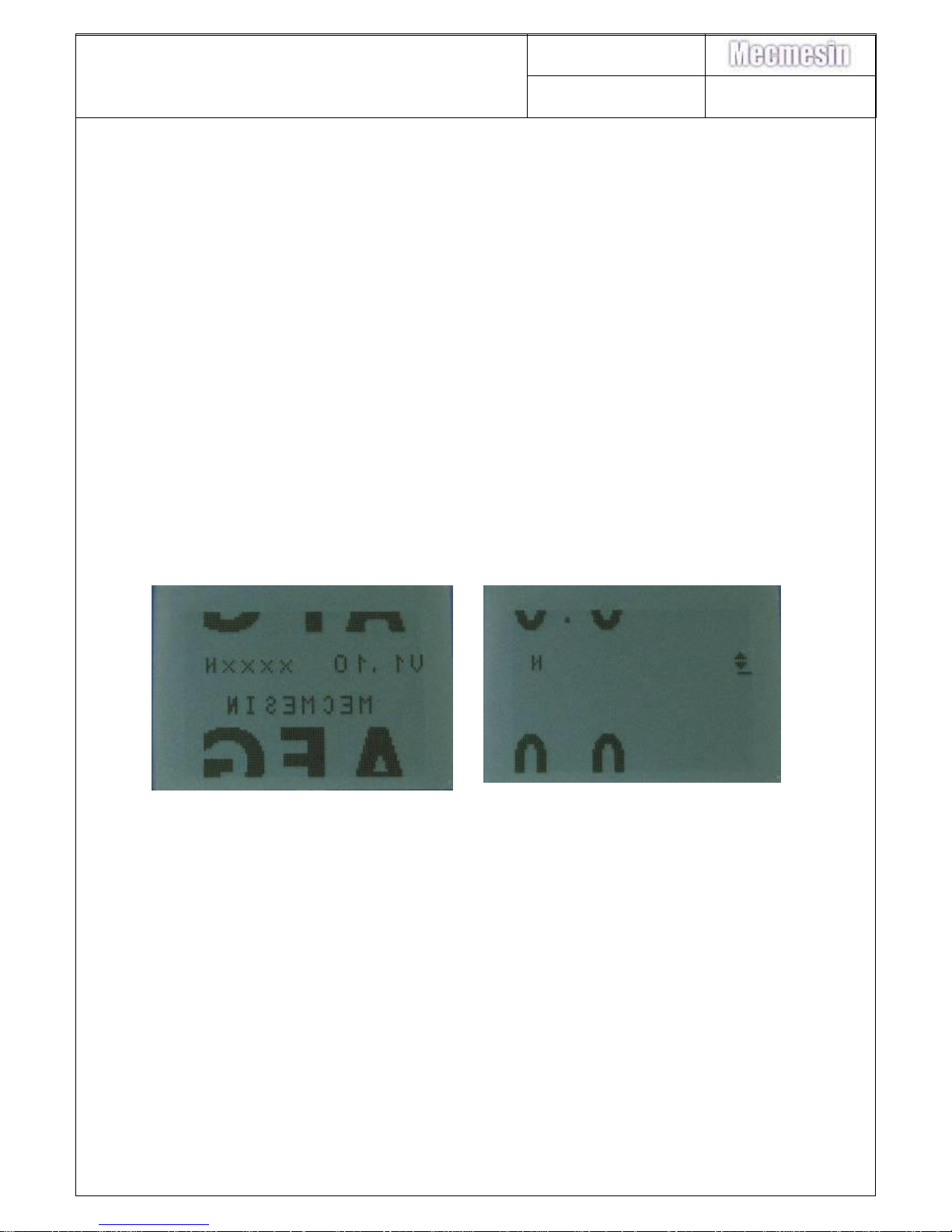
20. Test Display. If the LCD gives an unusual display the ribbon cable may not
have seated correctly in the header. Unclip the ribbon cable, remove and
reinsert into the header. Re-secure and retest.
Reassembly is the reverse of the above procedure.
Note: If the display has not originally been procured from Trident, then the software
will require upgrading to V1.12 or later. See section 4, 9 & 10.
11. Configuration of display 301-028 V1.06 – V1.10
This instruction provides the procedure for reconfiguring the LCD (301-028) of AFG
Mk4 PCB (300-157-V02) V1.06 – V1.10 (pre V1.12)
A change of LCD manufacturer has resulted for the need, in some instances for the
codes 3179 or 3178 to be entered into the Calibration menu to reconfigure the
display.
Introduction Screen
Home Display
If the configuration code 3179 has already been entered by the manufacturer, the
code 3178 will then have to be entered to display the text correctly.
If the LCD displays correctly the first time the gauge is switched on after a
replacement has been fitted, no configuration is required.
Configuring Display Format
21. Turn the Test PCB on using the On/Off button on the keypad ( - top left of
Test Gauge). The “Turn On” sequence should be
o The buzzer should sound
o The left hand LED should illuminate green
o The right hand LED should briefly illuminate orange, and then change to red.
o A MECMESIN AFG introduction screen should display briefly before
changing to the “home” display
Page 15
AFG/AFTI Mk 4
Service and Repair Manual
Number 022-614
Issue Number: 09
Page 15 of 47
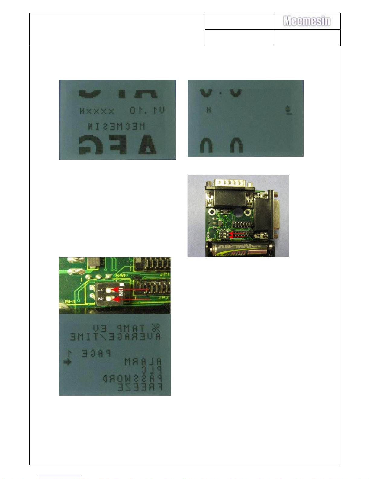
How to configure PCB to correct a display
which starts up inverted
Introduction Screen
Home Display
22. Ensure both DIP switches on SW1
are set to the off position
DIP switches set to off
23. Press and hold Units/Menu key
until menu is displayed.
Page 16
AFG/AFTI Mk 4
Service and Repair Manual
Number 022-614
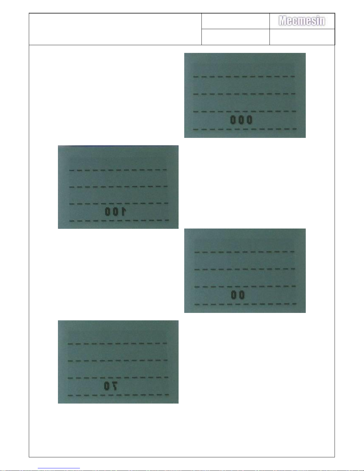
Issue Number: 09
Page 16 of 47
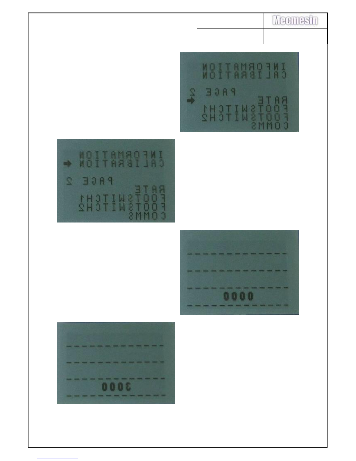
24. Press Units/Menu key again to
display page 2 of menu
25. Press TXD/UP key once until arrow
points to “CALIBRATION”
26. Press Reset/Enter key to enter
Calibration mode
27. Press TXD/UP key three (3) times
until 3000 is displayed
Page 17
AFG/AFTI Mk 4
Service and Repair Manual
Number 022-614
Issue Number: 09
Page 17 of 47
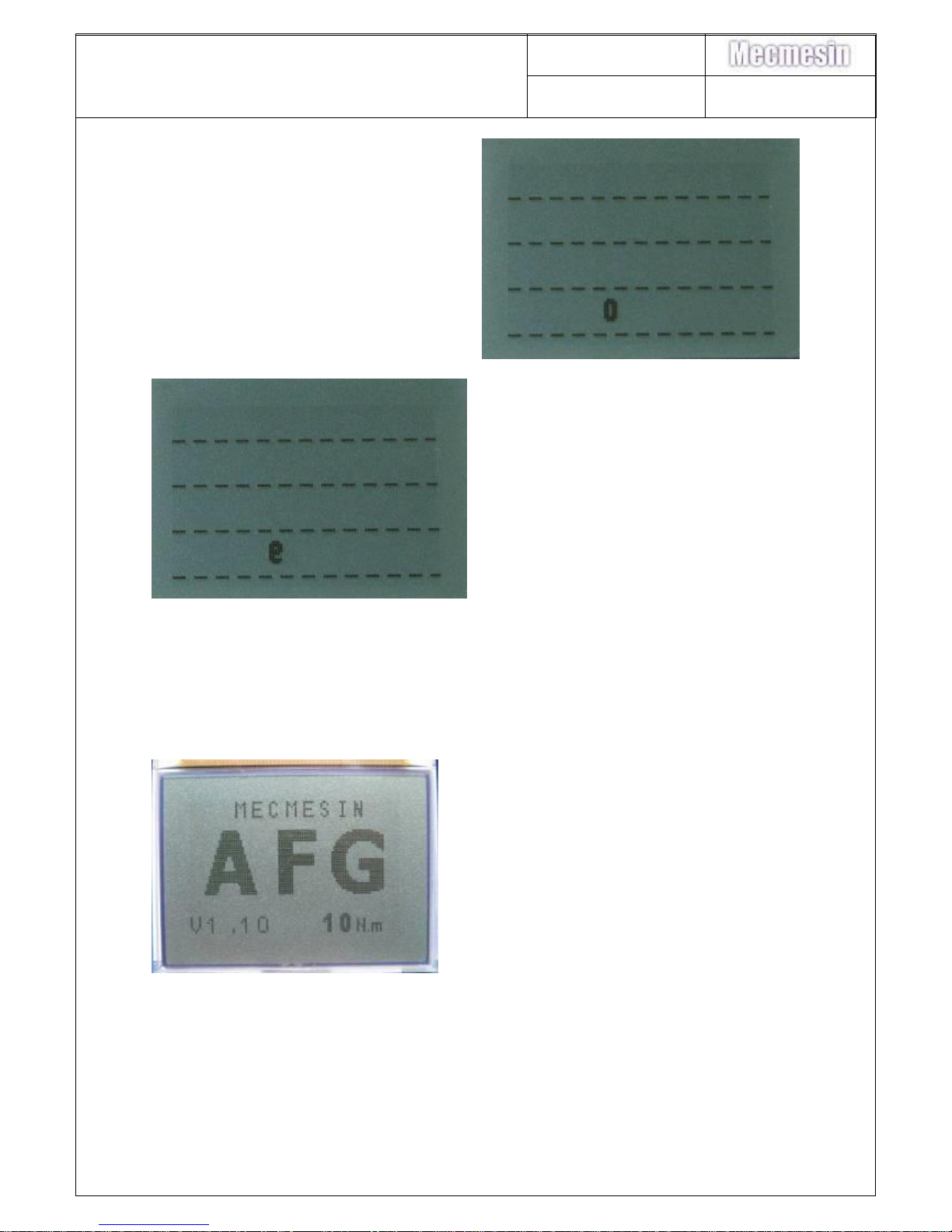
28. Press Reset/Enter key to enter first
number.
29. Press TXD/UP key one (1) times
until 100 is displayed.
30. Press Reset/Enter key to enter the
second number
31. Press TXD/UP key seven (7) times
until 70 is displayed.
Page 18
AFG/AFTI Mk 4
Service and Repair Manual
Number 022-614
Issue Number: 09
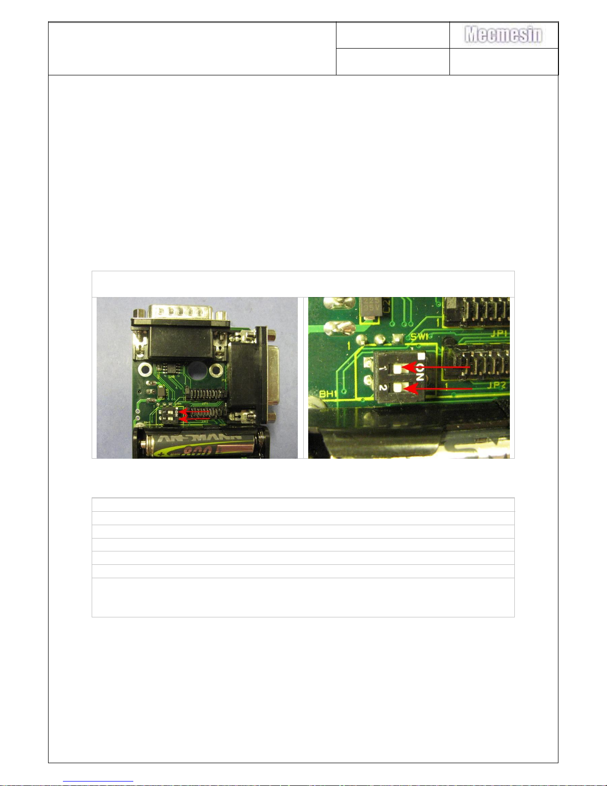
Page 18 of 47
32. Press Reset/Enter key to enter the
third number
33. Press TXD/UP key nine (9) times
until 9 is displayed.
34. Press Reset/Enter key to enter the
forth number
The LCD should then display page 2 of the Calibration menu correctly.
If the text is still inverted 3178 should be entered as above. Restart from instruction
6
35. Press Max/Esc key to return to
‘Home’ page
36. Turn PCB OFF and then back ON.
Text now should still be displayed
correctly
37. DIP Switch SW1 should then be
returned to the ON position.
Procedure ends.
Page 19
AFG/AFTI Mk 4
Service and Repair Manual
Number 022-614
Issue Number: 09
Page 19 of 47
12. Configuration of Display 301-028-V01 (V1.12)
If the AFG PCB (300-157-V02/3) is fitted with the latest display type and has been
programmed with the latest software (V1.12), then the gauge should operate as
required.
If an earlier generation display is used (i.e. alternative availability for Production or
Service) in combination with the V1.12 software, then the display will be blank and
will need to be set-up as described in this document.
301-028-V01 Display requires V1.12 or later to function correctly. See section 4
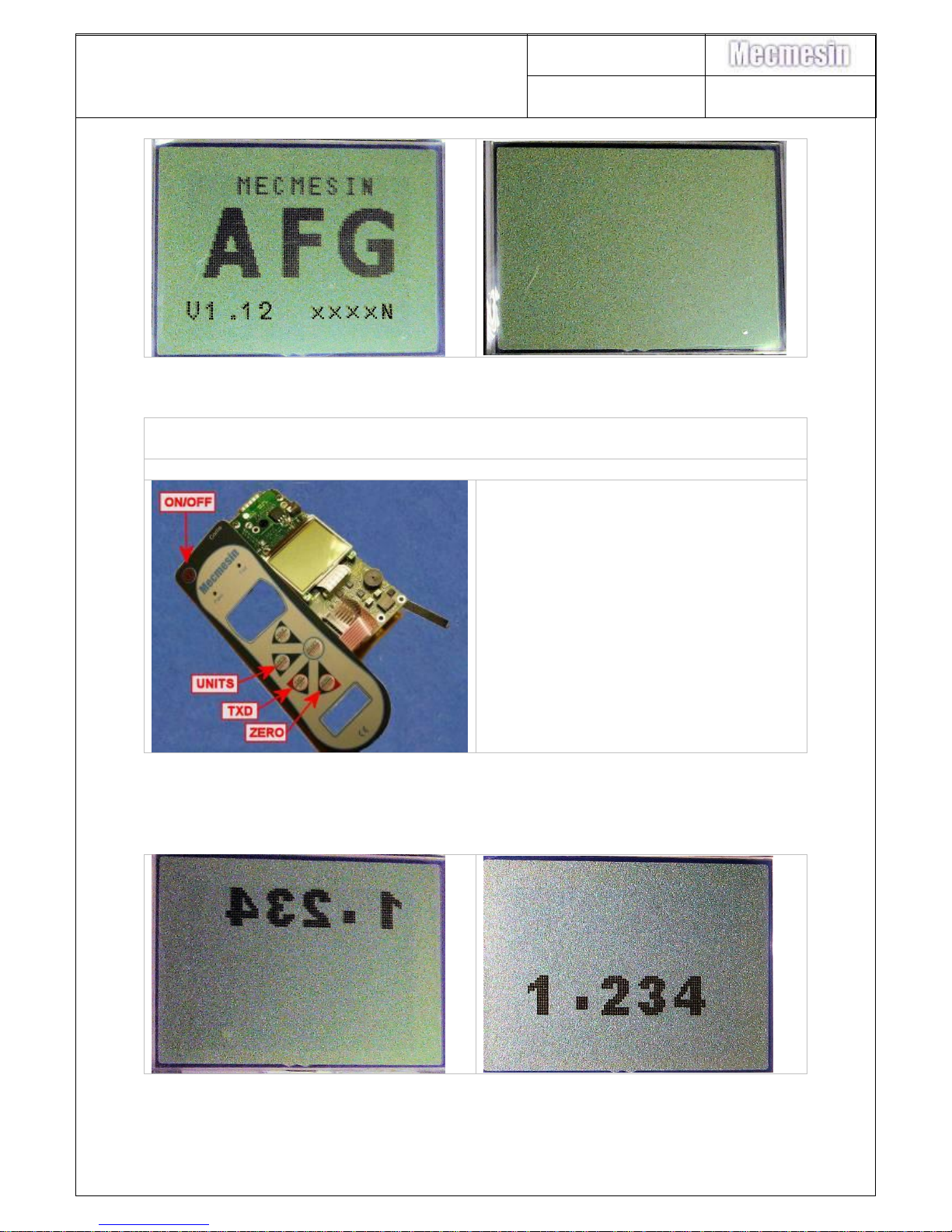
Protection switches
38. Ensure that the two PCB memory protection switches SW1 shown are in the
“OFF” position
Display Type Confirmation
39. Connect AFG Keypad to PCB, if not already connected.
40. Switch the PCB on and wait for a few seconds.
41. Switch the PCB off.
42. Switch the PCB on again. If the default display is fitted the “AFG” screen will
be visible. If one of the earlier/alternative displays is fitted the screen will be
blank
Page 20
AFG/AFTI Mk 4
Service and Repair Manual
Number 022-614
Issue Number: 09
Page 20 of 47
Display Configuration Procedure
43. If the screen is blank, follow the procedure below to identify and configure for
the display fitted
44. Ensure that the gauge is switched
OFF
45. Press and hold ZERO/TXD/UNITS
keys simultaneously
46. Press and release the ON key (still
holding ZERO/TXD/UNITS) – a
buzzer should sound continuously
while the keys are depressed.
47. Release the ZERO/TXD/UNITS
keys
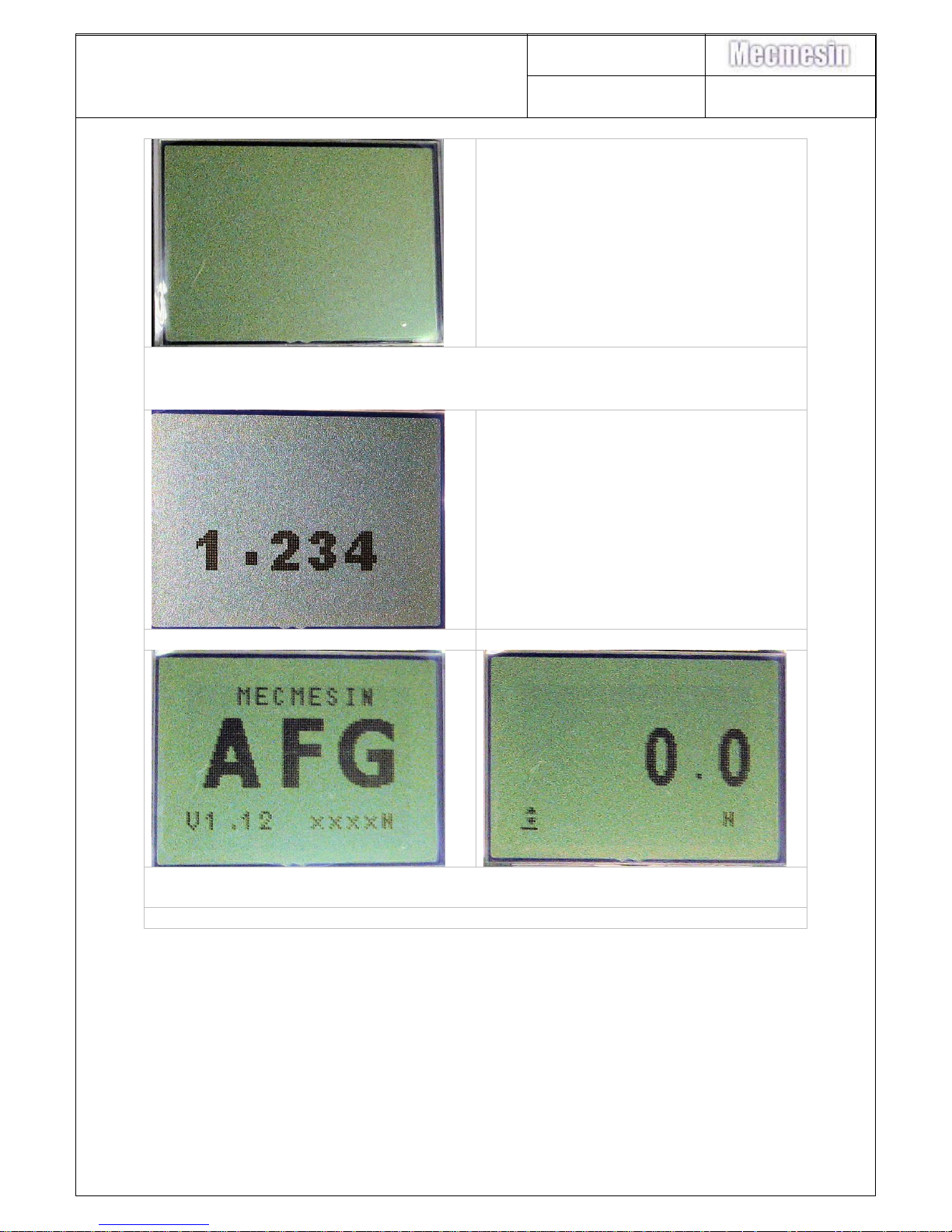
The screen may shown any of the options shown below (continues on next page).
Page 21
AFG/AFTI Mk 4
Service and Repair Manual
Number 022-614
Issue Number: 09
Page 21 of 47
48. If the ZERO key is pressed, the
buzzer should sound (indicating
that the next screen type has been
selected), and the screen should
change to the next option each
time ZERO is pressed.
49. Once the “1.234” option is
showing, press the RESET key to
store the display type to the
eeprom and exit the display setup.
NOTE: if required the MAX key can be
pressed to exit the display setup mode
without saving the new display settings.
50. CHECK:- Turn the gauge OFF and then back ON again …..the AFG screen
should show briefly, before changing to 0.0 on the working screen
51. Return PCB memory protection switches SW1 to ON
Page 22
AFG/AFTI Mk 4
Service and Repair Manual
Number 022-614
Issue Number: 09
Page 22 of 47
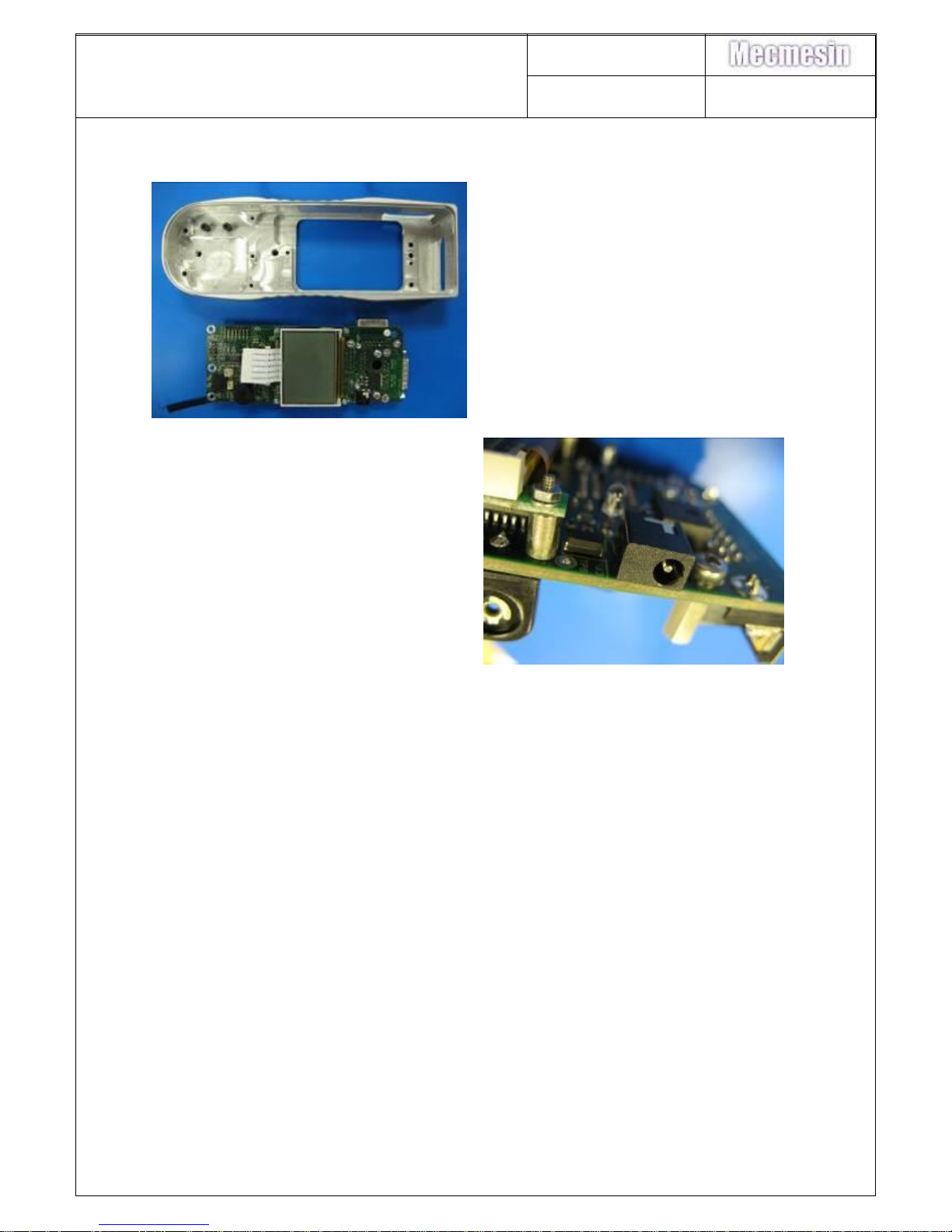
13. Charging socket replacement (329-355)
52. Remove PCB as per instructions 1
to 11 in section 6.
53. De-solder the damaged charging
socket and replace with new. Take
care over correct alignment and
quality of soldered joints.
Reassembly is the reverse of the above procedure
54. Once reassembled check the charging socket is aligned correctly by inserting
a charger
Page 23
AFG/AFTI Mk 4
Service and Repair Manual
Number 022-614
Issue Number: 09
Page 23 of 47
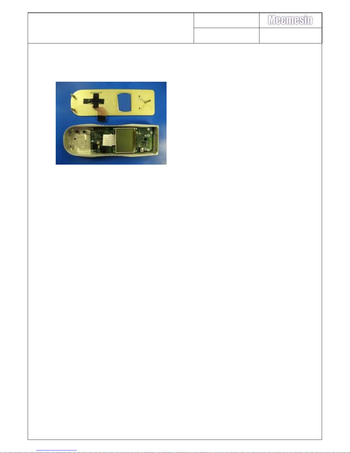
14. Keypad Membrane/Front Cover Plate replacement
For “Service” purposes the keypad is replaced as a complete assembly.
Procedures for preparing this assembly are detailed in AFG Mk 4 Assembly Work
Instruction (020-555).
55. Remove front panel assembly as
per instructions 1 to 7 in section 6.
56. Replace front panel assembly.
57. Test keypad functions.
Reassembly is the reverse of the above procedure
Page 24
AFG/AFTI Mk 4
Service and Repair Manual
Number 022-614
Issue Number: 09
Page 24 of 47
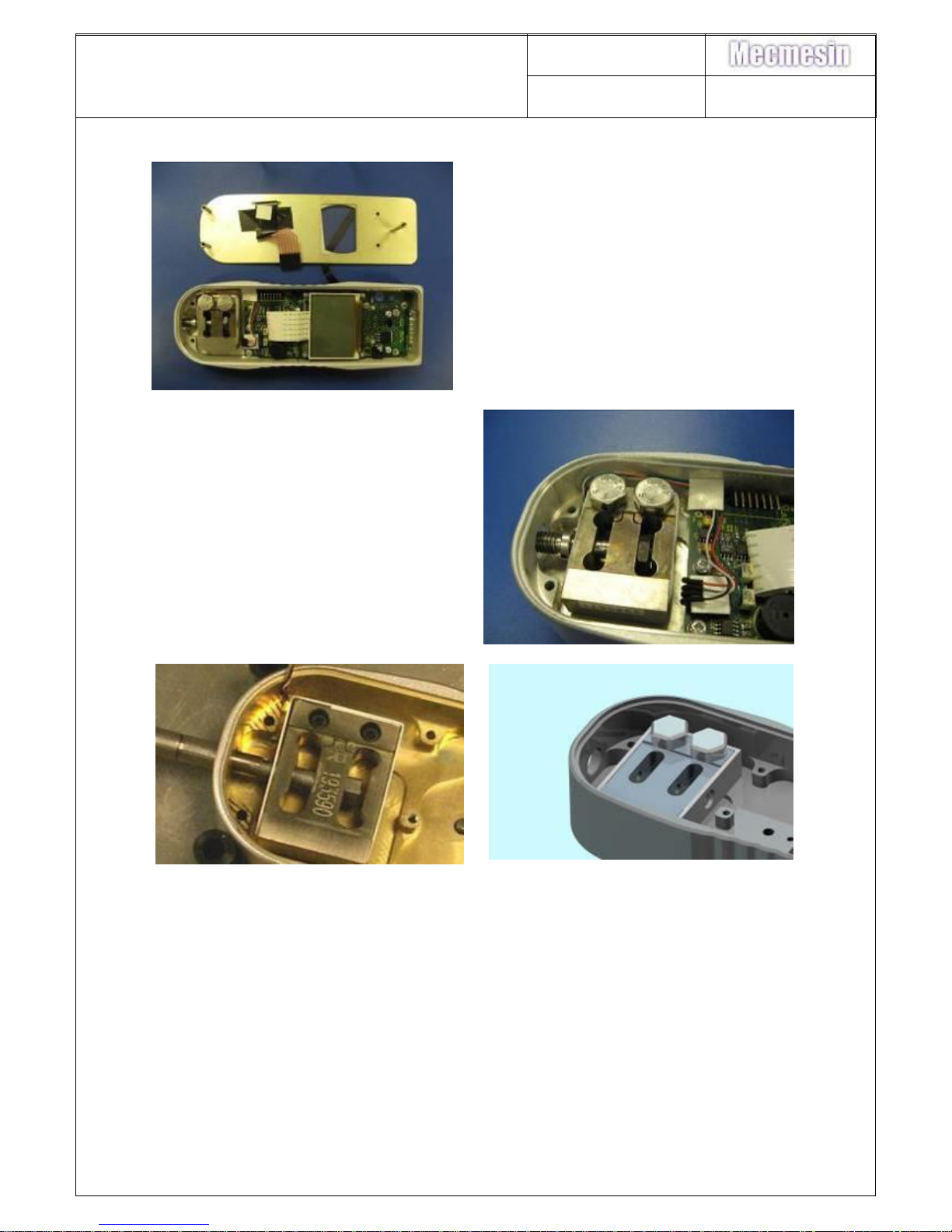
15. Load cell removal
58. Remove front panel assembly as
per instructions 1 to 7 in section 6.
59. BEFORE REMOVING LOADCELL
make careful note of the way it is
fitted – the routing of its wires,
positioning and use of sticky pads
etc – The replacement load cell
MUST be refitted in an identical
manner.
60. Load cells for 2.5N – 500N gauges
are retained with 2 off 6/32 UNC x
5/8” socket cap screws (420-265).
Remove with appropriate Allen
key. 2.5 & 5N load cells have
spacers (408-392) fitted.
61. Load cells for 1000N and 2500N
gauges are retained with 2 off M8 x
23 hex head screws (421-401).
Remove using appropriate socket.
62. The 2500N load cell maybe found
to have been pinned into position.
If so, a replacement 900-164-V02
AFG MK4 2500 PINNED L/C
ASSY is required.
Page 25
AFG/AFTI Mk 4
Service and Repair Manual
Number 022-614
Issue Number: 09
Page 25 of 47
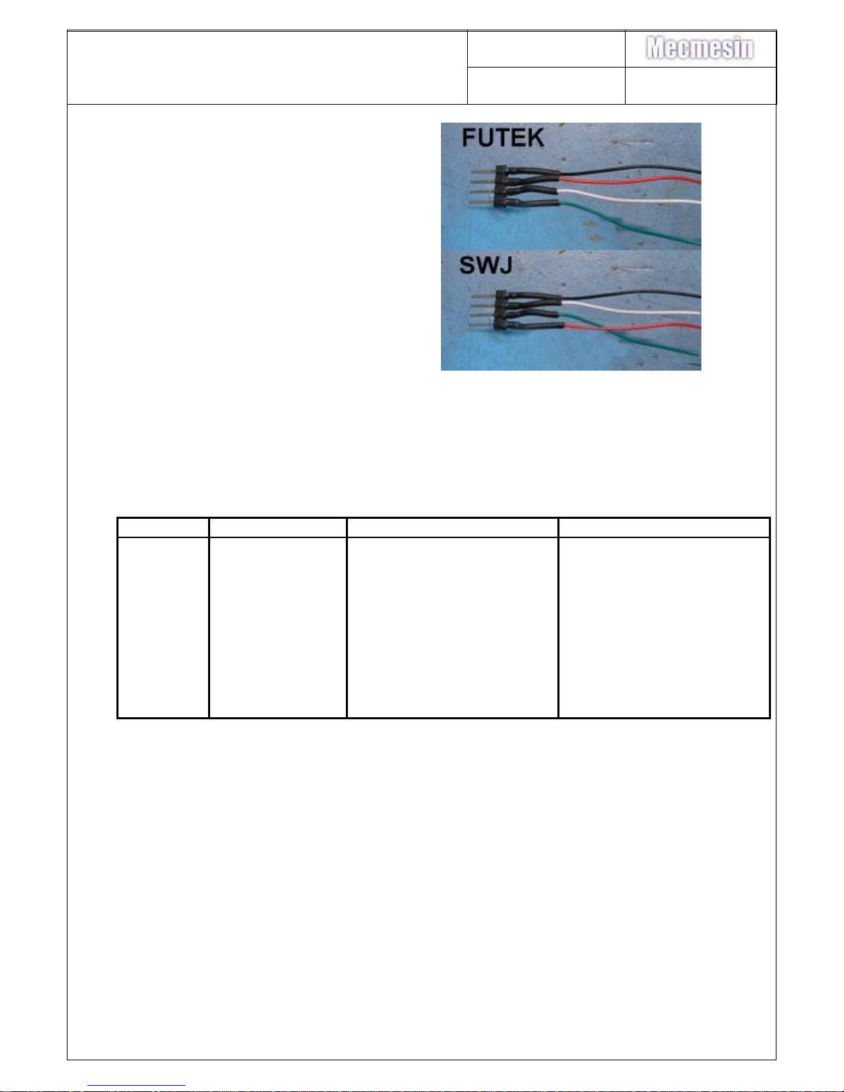
Futek load cell wiring:
Pin1: +ve Excitation - Green
Pin2: +ve Signal - White
Pin3: -ve Signal - Red
Pin 4: - ve Excitation – Black
SWJ load cell wiring
Pin1: +ve Excitation - Red
Pin2: +ve Signal - Green
Pin3: -ve Signal - White
Pin 4: - ve Excitation – Black
16. Load cell stud fitting.
NOTE: The replacement load cell stud and retaining nut type will depend on the
capacity of the load cell fitted:
Gauge
Load cell
Stud
Nut
2.5N
400-175
406-410
N/a
5N
406-410
406-410
N/a
10N
400-006-S01
406-408
420-138
25N
400-007-S01
406-408
420-138
50N
400-008-S01
406-408
420-138
100N
400-024-S01
406-408
420-138
250N
400-107-S01
406-408
420-138
500N
400-016-S01
406-408
420-138
1000N
900-302
406-409
420-316
2500N
900-164-V02
Pinned complete assembly
Pinned complete assembly
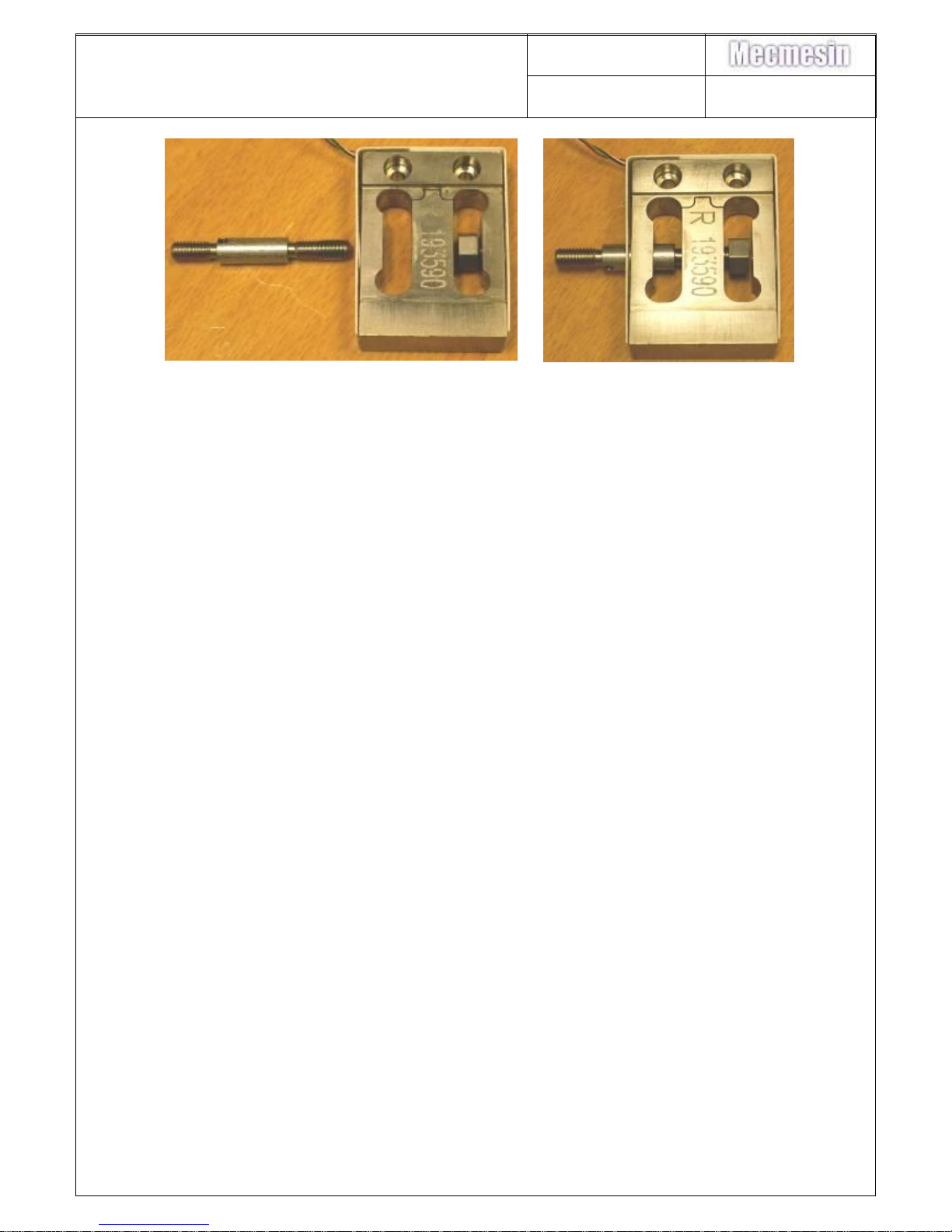
63. Degrease the load cell stud and nut and allow to dry.
64. Put a small amount of Loctite 243 on to the stud (opposite end to small hole).
During the load cell assembly routine, handle the load cell by central beam
only. Do not handle by any other means.
Page 26
AFG/AFTI Mk 4
Service and Repair Manual
Number 022-614
Issue Number: 09
Page 26 of 47
65. Holding the load cell by the central beam, screw the stud into the load cell
(from same side as connecting wire). As thread becomes available, screw on
the nut.
66. Tighten the load cell stud into position using a 2mm Allen key.
67. Tighten nut with spanner (possibly modified to fit into load cell).
68. Note: 1000 & 2500N load cells have no hole (use pliers) and the 5N and 2.5N
have no nut (just screw stud in with Loctite applied).
IMPORTANT: Clean any Loctite residue from the stud, load cell and nut.
Page 27
AFG/AFTI Mk 4
Service and Repair Manual
Number 022-614
Issue Number: 09
Page 27 of 47
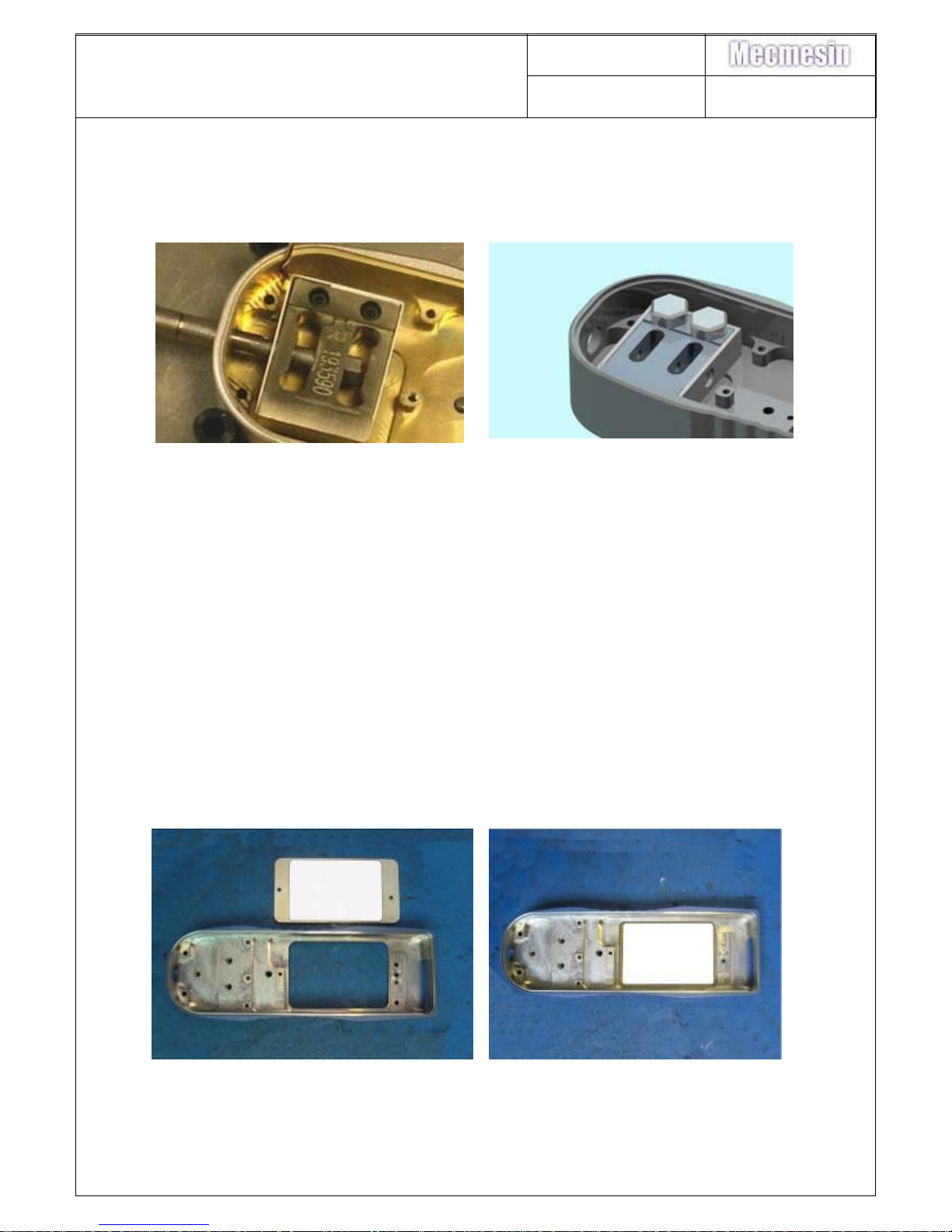
17. Load cell refitting
69. Put the load cell into the case and lightly screw down. Attach a long
extension rod and, ensuring the rod passes though the middle of the hole in
the casing, fully tighten the load cell screws to the appropriate torque – see
below:
70. Load cells for 2.5N – 500N gauges
are retained with 2 off 6/32 UNC x
5/8” socket cap screws (420-265).
2.5 & 5N load cells have spacers
(408-392) fitted. Tighten with
appropriate allen key, and torque
to 4Nm
71. Load cells for 1000N gauges are
retained with 2 off M8 x 23 hex
head screws ( 421-401) tightened
to 30Nm, 2500N load cells are now
pinned into position and come as a
complete assembly.
72. Remove the extension rod.
73. Reconnect the load cell to the PCB.
Reassembly is the reverse of procedure
18. Battery lid/insulator replacement
Remove battery cover as per instructions 1 to 2.
Remove insulator from lid – remove any adhesive residue with a suitable cleaner
Page 28
AFG/AFTI Mk 4
Service and Repair Manual
Number 022-614
Issue Number: 09
Page 28 of 47
74. Stick battery cover insulator (410-586) to inside of battery cover (404-161F11) as in photographs such that it is centred from all four sides of battery
compartment with the cover the correct way round
19. Firmware version – Identification.
The software (firmware) version is found on the bottom left hand corner of the
display, the version number is only displayed on the screen when the gauge is first
switched on during the start-up routine.
20. Firmware release notes
Implemented in version 1.12 (DCR1847) from serial number: 11-0176-06 to 11-0283-
09 then returned to V1.10 as previous LCD procured.
-------------------------
1) Different contrast setting added for new displays
Implemented in version 1.11 (DCR1847) (Not released)
-------------------------
1) Changes made to allow 3 different displays to be used
Implemented in version 1.10 (DCR1661) from serial number: 10-0133-02
-------------------------
1) Incorrect Slopes for Smarts (Flyspray ID188)
- Bug fixed where tension slope was being used for compression and
compression slope was being used for tension in Smarts
- Load cell polarity for Smarts now displayed correctly in
Information Page
(Smart overloads are not recorded).
Implemented in version 1.09 (DCR1608) from serial number 09-0131-07
Page 29
AFG/AFTI Mk 4
Service and Repair Manual
Number 022-614
Issue Number: 09
Page 29 of 47
-------------------------
AFTI 09-0130-02, 09-0029-07, 09-0030-07, 09-0031-07, 09-0032-07, 09-0033-07.
AFG 1000N 09-0104-07, 09-0105-07, 09-0106-07, 09-0107-07, 09-0108-07
AFG 500N 09-0177-06
AFG 250N 09-0111-07, 09-0113-07, 09-0114-07
AFG 50N 09-0080-07
AFG 10N 09-0085-07
AFG 5N 09-0120-05, 09-0088-07
AFG 2.5N 09-0193-03, 09-0006-06, 09-0093-06
1) Smart Overload Counter (Flyspray ID153 continued)
- Bug fixed where eeprom data in certain Smarts was not being
read correctly on boot-up or when 'defaults' function used
Implemented in version 1.08 (DCR1608) (Not released)
-------------------------
1) Smart Overload Counter (Flyspray ID153)
- Smart overload counter removed as smart calibration data was
being corrupted which produced an 'E Err' message when the Smart
is connected to an AFG Mk2
- Corrupted Smart data is restored upon boot-up by copying
uncorrupted data to corrupted data image
Implemented in version 1.07 (DCR 1567) from serial number 09-0104-04
-------------------------
09-0125-02, 09-0027-02, 09-0130-02, 09-0211-02, 09-0130-03, 09-0131-03, 09-0132-03, 09-0045-04,
09-0046-04, 09-0047-04, 09-0048-04, 09-0049-04, 09-0050-04, 09-0051-04, 09-0052-04, 09-0053-04,
09-0054-04
FS#49 - Menu Pages in Uncalibrated PCBs
Before a PCB has been calibrated, the menu pages are not configured correctly i.e.
entering the PLC menu takes the user to the alarm settings.
Note that once the PCB has been calibrated everything works ok.
FS#114 - Setting the defaults causes an eeprom error when a Smart is connected
Invoking the ‘Set Defaults’ option within the menu pages produces an ‘Eeprom Read
Error Code 2’ message when a Smart is connected. When a Chinese display is used
on the gauge this causes corruption of the display configuration byte and hence the
display is not configured correctly. Note that the data is only read incorrectly at this
stage - turning the gauge off then back on again will read the eeprom correctly.
FS#115 - Overload Counter Not Updated for Smarts
Page 30
AFG/AFTI Mk 4
Service and Repair Manual
Number 022-614
Issue Number: 09
Page 30 of 47
When a Smart is connected and overloaded the overload counter does not get
incremented.
FS#116 - 'Footswitch 2 Not Available' Message Flickering
When a Smart is connected and the Footswitch 2 menu page is entered, the
‘Footswitch 2 Not available’ message flickers
FS#120 - Cannot calibrate in kgf.cm or lbf.in
Performing the adjustment in kgf.cm or lbf.in causes the gauge to go into overload
upon leaving the calibration routine.
FS#121 - Line separating load limits in alarm menu in incorrect position
The line separating the load limits within the alarm menu is not in the correct position
when the new displays are used. Additionally, when changing the ‘g constant’, the ‘g
constant’ value is re-written on the screen when using the new displays.
FS#122 - g constant has no upper and lower limits
The ‘g constant’ in the menu pages (accessed via the password page) has no upper
and lower limits. This means it can not only be increased indefinitely, but also
decreased to a negative value. It is suggested to limit the ‘g constant’ to between
9.00000 and 9.99999.
The ‘g constant’ is not rounded correctly when being altered due to the
addition/subtraction of a floating point number to change it.
Implemented in version 1.06 (DCR 1557) from serial number 09-0176-01
-------------------------
1) New displays not working when a Smart is connected. (Flyspray ID110).
- When a Smart is connected the ‘display type’ stored in memory is not read
correctly and the software cannot be configured for use with the new Chinese
displays.
Implemented in version 1.05 (DCR 1519) serial numbers 09-0246-01 to 09-0255-01,
09-0265-01, 09-0295-01, 09-0296-01, 09-0297-01 & 09-0301-01
-------------------------
1) Replacement; 301-028-V01 GRAPHIC LCD 64x 100 Resolutions. (Flyspray
ID104)
- New displays are configured differently and require the software to be altered
so that they operate correctly. This software allows the gauge to be configured
to use either the old or new display.
Page 31
AFG/AFTI Mk 4
Service and Repair Manual
Number 022-614
Issue Number: 09
Page 31 of 47
2) Remove load sign change feature in calibration routine. (Flyspray ID76)
- The calibration routine contains a feature that allows the load sign to be
changed if the load cell has been wired incorrectly. However, although it alters
it for the digital side of the gauge, the polarity of the analogue output remains
incorrect. Therefore the feature needs to be removed so that if a load cell is
wired incorrectly, the load cell should be removed and wired the correct way.
Implemented in version 1.04 (DCR1464) from serial number 08-0168-08
-------------------------
1) Auto-off Eeprom address (Flyspray ID27)
- Auto-off eeprom address moved as overwrote Rate in eeprom
causing gauge to enter 'High Rate' mode which was perceived
as noise in the Orbis
2) Zero Blanking (Flyspray ID28)
- Zero blanking added for high rate so that any load to be
displayed that is less than the accuracy of the gauge is
displayed as zero
3) Loadbar sign (Flyspray ID29)
- Loadbar now always correct appearance
4) Calibration in non-SI units (Flyspray ID40)
- Calibration routine allows calibration in units other than
N and Nm
Implemented in version 1.03 (DCR1444)
-------------------------
1) Calibration Routine
- Calibration routine not entered if Smart connected
2) Turning on with Smart connected
- Delay added to allow hardware to switch to Smart load
3) Torque Smarts
- Smart Torques displayed as correct type and not as force
Implemented in version 1.02 (DCR 1434) (Not Released)
-------------------------
1) Calibration Routine
- Low battery symbol check added to calibration routine
Page 32
AFG/AFTI Mk 4
Service and Repair Manual
Number 022-614
Issue Number: 09
Page 32 of 47
- Check added to ensure all calibration data stored correctly
- Message displayed when calibration data stored correctly
- Disable skipping of calibration steps if gauge type changed
2) Memory Counter
- Memory counter stored in eeprom after memory cleared
3) Digmatic
- Timeout reduced
4) AFTI Selection
- AFTI can be selected without gauge having to be set up as AFG
first
Implemented in version 1.01 from serial number 08-0118-03 (Three page menu version)
-------------------------
1) Calibration Routine
- PC Commands working in Calibration Routine. CTRL+A, CTRL+B,
CTRL+C, CTRL+D, CTRL+E received via RS232 enabled in cal routine
to simulate keys. Enabled from load cell size select page up to
(but not including) new 'Store Data' page
- All interrupts disabled in correct place as gauge could 'lock up'
if auto-off/backlight enabled
- Calibration steps can be skipped using the TXD key
- Extra stage at end of calibration routine added to prompt user to
store data
2) X-Constant
- Floating point rounding error fixed when determining decimal
places for new X-constant value
- Maximum number of allowed decimal places reduced
- Loads stored and read with correct units and decimal places when
X-constant enabled/disabled
- Correct data formatting used after X-Constant enabled/changed
- Units key now working correctly within X-Constant page
3) Configuration Status request
- Unrequired blank spaces before Stand Cycles removed
4) Cycle Counter
- Cycle Counter displayed as default if memory counter also used
5) Stand Cycle Limits Menu
- Menu page now exited properly with MAX key
Page 33
AFG/AFTI Mk 4
Service and Repair Manual
Number 022-614
Issue Number: 09
Page 33 of 47
6) Overload Symbol
- Displaying (and clearing) the overload symbol in the timer
interrupt routine removed as corruption to display could occur
when 30 second timeout ended. 'OL' symbol now displayed/cleared
as appropriate in main loop
Page 34
AFG/AFTI Mk 4
Service and Repair Manual
Number 022-614
Issue Number: 09
Page 34 of 47
21. PCB Conversion - AFTI to or AFG or Tornado or Orbis
If a gauge PCB has already been set-up and calibrated as one of the above and you
wish to install the PCB into a different type of gauge:
At the calibration screen enter 9999 select which gauge type you require and
complete the calibration/adjustment sequence.
NB: If the PCB has been set as an ATFI press UNITS & ENTER to access the
calibration pages
AFTI Mk4 PCB conversion to AFG, Orbis, Tornado.
Turn the gauge on without a Smart connected:
The display reads:
ERROR
NO SMART
Press UNITS & ENTER at the same time, once released the calibration menu is
accessed:
The display reads
- - - - - - - - - - - - - - - -
0000
- - - - - - - - - - - - - - - -
- - - - - - - - - - - - - - - -
- - - - - - - - - - - - - - - -
Enter the code “9999” to enter the Calibration routine. Enter the code one number at
a time using the following keys:
TXD - increases the number
ZERO - reduces the number.
ENTER- accepts the number.
The display reads
SELECT GAUGE
- - - - - - - - - - - - - - - -
AFG ◄
- - - - - - - - - - - - - - - -
ORBIS
- - - - - - - - - - - - - - - -
TORNADO
- - - - - - - - - - - - - - - -
Select required gauge type, adjust and calibrate using the appropriate work
instruction.
Page 35
AFG/AFTI Mk 4
Service and Repair Manual
Number 022-614
Issue Number: 09
Page 35 of 47
22. Latency
What is the maximum transfer rate from an AFG Mk4?
What is the latency between the data being recorded and transmitted?
The rate settings make no difference to the data transmission rates in the new
software.
1. The maximum latency from request (e.g. receiving a ‘?’) to the start of data being
transmitted is approximately 12ms, for both RS232 (all baud rates) and Digimatic.
The data could be up to 20ms old before it is transmitted.
2. For RS232 transmission the maximum data rate depends on the format
transmitted. If units and the sign are transmitted the data rate will be reduced as
there is more to transmit.
At 9600, the guaranteed maximum rate is approximately 29Hz (continuous
transmission function operates at 25Hz at this baud rate).
At 115200 this is increased to approximately 70Hz (continuous transmission function
operates at 50Hz at this baud rate).
Note, however, that new data is only ‘available’ for transmission every 20ms, so
sampling faster than 50Hz would result in the same data being repeated
occasionally.
3. Determining the maximum data transmission rate for Digimatic is difficult as it
depends greatly on the speed the connected Digimatic device can operate at (e.g.
the Mahr printer can operate faster than some of the older Mitutoyo devices). From a
Digimatic request to complete load transmission (regardless of connected device)
takes a maximum of approximately 150ms. Therefore, theoretically, data could be
transmitted approximately every 150ms (6.6Hz) if requested. If not requested, i.e. in
continuous transmission mode, the transmission rate could be increased to a
maximum of approximately 30Hz
Page 36
AFG/AFTI Mk 4
Service and Repair Manual
Number 022-614
Issue Number: 09
Page 36 of 47
23. Display contrast setting.
The user configurable contrast setting option was removed from the menu in version
1.00.
In version 1.07 onwards, altering the contrast can be accessed by entering '7777' in
the password (calibration) page.
To alter the contrast setting –
Turn the gauge on
Enter the menu screen by holding the MENU key down.
Select page 2 of the Menu by pressing the MENU key, select CALIBRATION (by
using UP/DOWN keys) and press ENTER. The display will now show:
- - - - - - - - - - - - - - - -
0000
- - - - - - - - - - - - - - - -
- - - - - - - - - - - - - - - -
- - - - - - - - - - - - - - - -
Enter the code “7777” to go into the Contrast adjustment routine.
Enter the code one number at a time using the following keys:
UP - increases the number.
DOWN - reduces the number.
ENTER - accepts the number.
Although it may not be visible the display will show ‘1.234’.
Press the UP button and the matrix will become darker. Pressing the DOWN button
will make the matrix lighter.
Press the ENTER button to save the desired setting.
Page 37

AFG/AFTI Mk 4
Service and Repair Manual
Number 022-614
Issue Number: 09
Page 37 of 47
24. AFG & AFTI Analogue Output.
300-157-V01 AFG PCB: February 2008, a change has been made to the PCB to help
reduce costs. The PCB can now be purchased without the analogue calibration
circuitry
300-157-v02 AFG PCB without analogue calibration circuitry.
300-157-v03 AFG PCB with analogue calibration circuitry.
Internal Load cell (No load applied)
Pin 10 to Pin 1: ~0.0V (Non calibrated Analogue output can range between -4.0V to
+4.0V with offset ~0.0V)
Pin 10 to Pin 1: ~0.0V (Calibrated Analogue output will range between -4.0V to +4.0V
with offset 0.0V)
Pin 9 to Pin 1: ~5.0V (Footswitch input)
Non calibrated analogue output range and offset for internal load cell will be
dependant the on mV/V and offset of load cell and analogue circuit of the AFG.
External Load cell (No load applied)
Pin 10 to Pin 1: ~1.25V (Non calibrated Analogue output can range between 0.0V to
+2.5V with offset ~1.25V)
Pin 9 to Pin 1: ~0.0V (Non calibrated Analogue output can range between -1.25V to
+1.25V with offset ~0.0V)
Non calibrated analogue output range and offset of the external load cell will be
dependant on mV/V and offset of load cell sensor will not be affected by the
AFG/AFTI it is attached to.
The AFG/AFTI Analogue output functions as follows:
When no 'smart' sensor is connected:
· Analogue output is taken from Pin 1 (+ve) and Pin 10 (-ve)
· The foot-switch can be connected across Pin 9 and Pin 10
When a 'smart' sensor is connected:
· Analogue output is taken from Pin 1 (+ve) and Pin 9 (-ve)
· Under absolutely no circumstances should a foot-switch be connected
Page 38
AFG/AFTI Mk 4
Service and Repair Manual
Number 022-614
Issue Number: 09
Page 38 of 47
The switching of Pin 9 functionality is automatically triggered by the
presence/absence of a 'smart' connector.
Page 39
AFG/AFTI Mk 4
Service and Repair Manual
Number 022-614
Issue Number: 09
Page 39 of 47
25. Fault finding.
Gauge Fault
Remedy
1. Gauge will not switch on.
Check batteries for corrosion, clean terminals,
replace batteries.
Check without batteries, with charger plugged
in. If this rectifies the problem, then remove
charger and fit new batteries.
Check battery charger output; should read
approximately 100mA constant current.
Check keypad functions, check with known
working keypad.
Check PCB for liquid ingress.
Replace PCB.
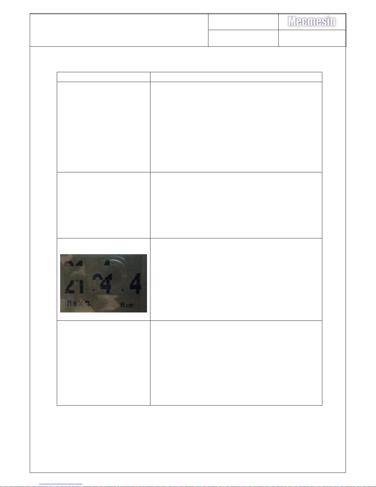
2. No display
Possible causes as above in ‘Gauge will not switch
on’.
Operator has changed contrast. Restore
contrast setting. (Software version dependent).
Display not configured/V1.12 or later firmware.
Check display ribbon cable connection.
Check with a known working LCD
Replace PCB.
3. Display behaves
unusually
If the LCD gives an unusual display the ribbon cable
may not have seated correctly in the header. Unclip
the ribbon cable, remove and reinsert into the header.
Re-secure and retest.
Check LCD ribbon cable connection.
See Section 10 Display Replacement.
Check with a known working LCD
Replace LCD.
4. OL shown on display
If OL is shown on the top left of the display, record
load cell offset. See section 5
If the recorded offset is below 5% should be okay.
Between 5 and 10%, take millivolt offset.
Above 10% possible replacement load cell.
If gauge beeps continuously and full load bar is
illuminated at the bottom of LCD. Record millivolt
offset. Load cell pins 2 + 3 should read ideally 0.0
mV.d.c. Highest acceptable limit is +/- 0.8 mV.d.c. If
above, replace load cell.
Page 40
AFG/AFTI Mk 4
Service and Repair Manual
Number 022-614
Issue Number: 09
Page 40 of 47
5. Display does not alter
with applied load.
Check gauge user configurable settings, max
reading set, average over time, etc. Factory
default gauge settings.
Check load cell connection.
Check load cells mV offset alters with applied
load.
Test with known working load cell.
Test with known working PCB
Also see 11 below.
Replace load cell / PCB.
6. Keypad doesn’t work.
Check keypad connection with PCB
Check PCB for liquid ingress.
Test with known working keypad
Replace PCB / Keypad
7. LCD shows
- - - - - - - - - - - - - - - -
0000
- - - - - - - - - - - - - - - -
When the MENU key is
pressed.
PASSWORD Function enabled. Refer to latest
Operating Manual. (Enter 6284 to unlock).
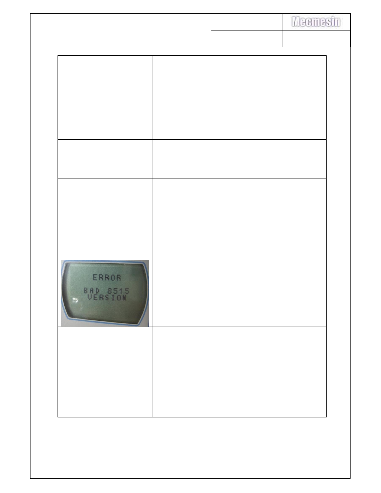
8. LCD displays.
Reprogram the PCB with the latest version of
firmware (see section 4), whilst programming,
ensure that the lockbits and fuses are set
correctly.
9. LCD flashing and/or
buzzer sounding with a
Smart connected.
When the AFG Mk4 was introduced the
charger was upgraded from 60mA CC to
100mA CC as the charger could not sustain
the PCB's power requirement with a Smart
connected. (Worse case scenario for AFG
current draw; Smart connected and back-light
on).
Ensure that the charger is 100mA CC and
supplied by Mecmesin.
Check charger output with a DVM – 100mA
CC
Page 41
AFG/AFTI Mk 4
Service and Repair Manual
Number 022-614
Issue Number: 09
Page 41 of 47
10. Overload register does
not record overloads /
Contrast settings not held
A batch of PCB’s had an incorrect 306-508
EEPROM fitted. The IC could not be written to
with the protection switches enabled. To
check that the correct IC has been fitted enter
9876 into the Calibration menu, the display will
return "EPROM TEST OK" message. (If an
incorrect EEPROM is fitted then the gauge will
return "EEPROM protection ERROR Code1"
message).
11. Load reading appears
low
See section 4.
Incorrect dovetail mounting screw coul
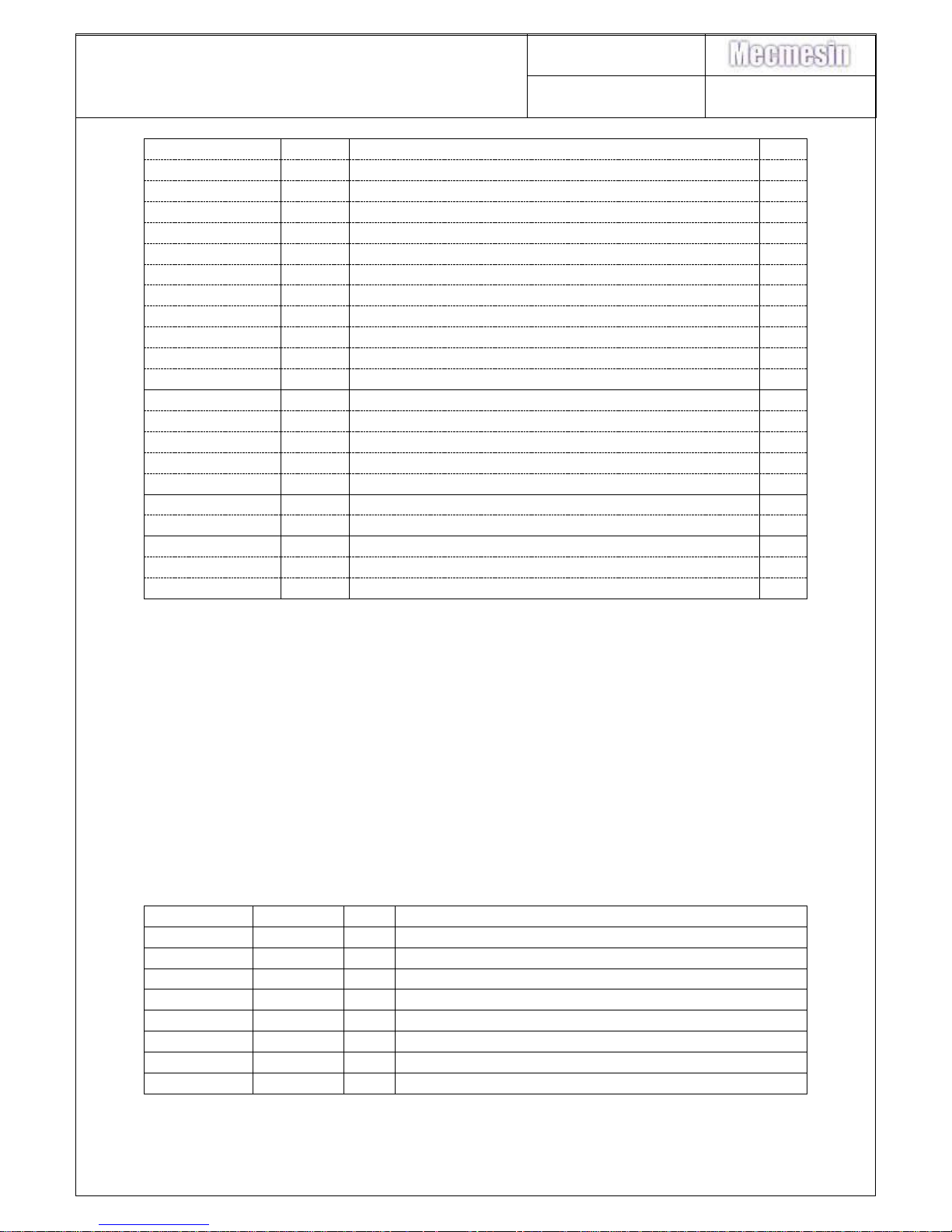
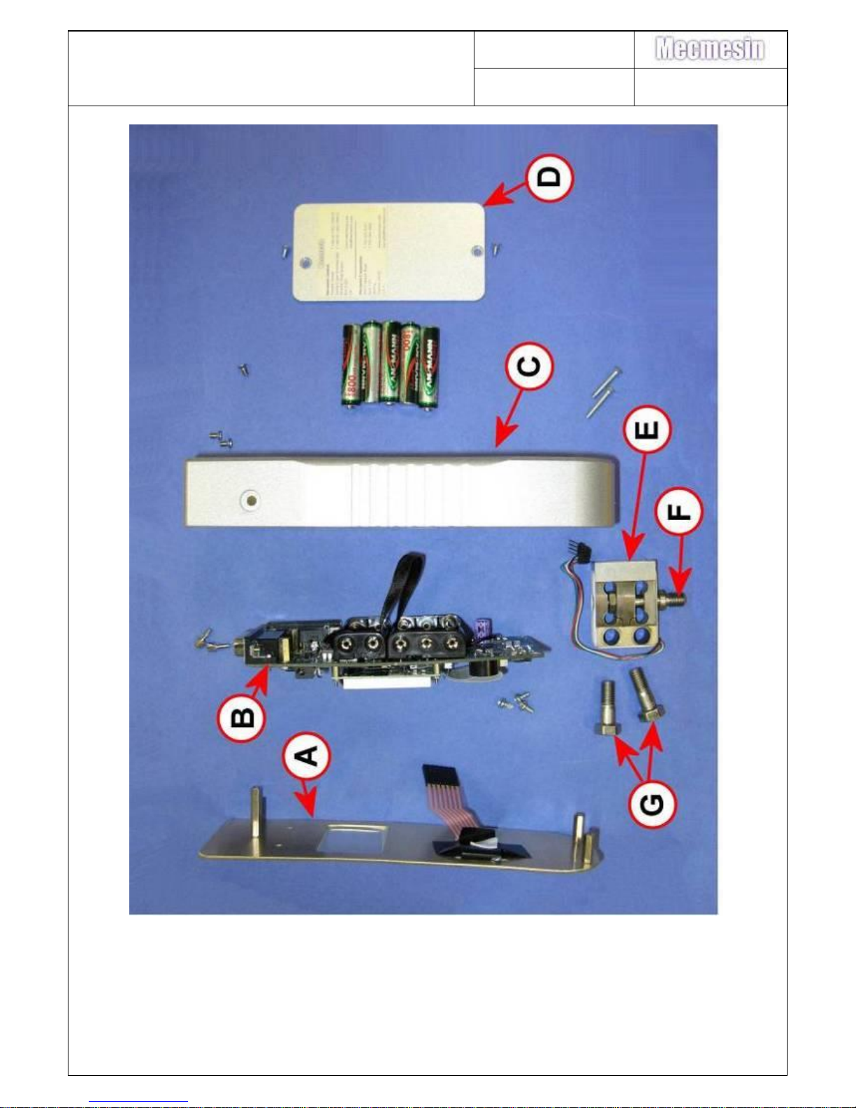
26. Spare parts list
410-540
1
AFG MK4 2500N LABEL
A
410-539
1
AFG MK4 1000N LABEL
410-538
1
AFG MK4 500N LABEL
410-537
1
AFG MK4 250N LABEL
410-536
1
AFG MK4 100N LABEL
410-535
1
AFG MK4 50N LABEL
410-534
1
AFG MK4 25N LABEL
410-533
1
AFG MK4 10N LABEL
410-532
1
AFG MK4 5N LABEL
410-531
1
AFG MK4 2.5N LABEL
410-515
1
AFG MK4 KEYPAD must be affixed to 404-159
420-378
2
M3 x 20 SCREW POZI CSK ZINC
420-357
3
SCREW M3 x 6 CSK POZI (SS)
404-159
1
AFG FRONT COVER PLATE
300-157-V02
300-157-V03
1
1
AFG Mk4 PCB - No analogue output adjustment
AFG Mk4 PCB - With analogue output adjustment
B
301-028-V01
1
DISPLAY
329-355
1
CHARGING SOCKET
328-005
1
SOUNDER
420-357
2
SCREW M3 x 6 CSK POZI (SS)
420-285
2
M3x6 SCREW POZI PAN HEAD
420-035
3
SCREW TAPTITE PAN POSI M3x6
412-021
1
15 WAY D FEMALE CON COVER
412-020
1
15 WAY D MALE CON COVER
404-161-F11
1
AFG MK4 BATTERY COVER
D
410-586
1
LABEL AFG BAT COVER INSULATOR
420-296
2
M3x6 SCREW MACHINE CSK SLOT
Page 42
AFG/AFTI Mk 4
Service and Repair Manual
Number 022-614
Issue Number: 09
Page 42 of 47
400-175-
1
LOAD CELL 2½N (½LB)
E
400-034-
1
LOAD CELL 5N (1LB)
400-006-S01
1
LOAD CELL 10N (2.2LB)
400-007-S01
1
LOAD CELL 25N (5LB)
400-008-S01
1
LOAD CELL 50N (10LB)
400-024-S01
1
LOAD CELL 100N (25LB)
400-107-S01
1
LOAD CELL 250N (50LB)
400-016-S01
1
LOAD CELL 500N (100LB)
900-302
1
AFG/BFG LOADCELL KIT 1000N
900-164-V02
1
2500N PINNED LOAD CELL ASSEMBLY
408-392
1
LOADCELL SPACER FOR 2.5-5N
329-187
1
4WAY HEADER 0.1 PI G'PLAT
406-410
1
AFG MK4 L/CELL STUD 10/32 2.5 / 5N
F
406-409
1
AFG MK4 L'CELL STUD 1/4-5/16un 1000/2500N
406-408
1
AFG MK4 LOADCELL STUD 10 / 500N
420-138
1
AFG MK4 LOADCELL STUD NUT 10 / 500N
420-316
1
AFG MK4 LOADCELL STUD NUT 1000 / 2500N
420-265
2
SCREW CAP SKT 6-32UNCx5/8" – 2.5 / 500N
G
420-401
2
M8x23 Hex Bolt s/s – 1000 / 2500N
408-428-F11
1
AFG MK4 2.5 / 500N CASE (FUTEK)
C
408-427-F11
1
AFG MK4 1000 / 2500N CASE (PARRA M8)
408-432-F11
1
AFTI MK4 CASE
AFG XXX N Front panel complete, comprising of;
404-159 1.000 AFG MK4 FRONT COVER PLATE
420-230 3.000 PRESS STUD M3 x 8
424-027 2.000 HEXSPACER M3 x 14 F/F MODIFIED
424-046 1.000 HEXSPACER M3 x 25 F/F MODIFIED
410-515 1.000 AFG MK4 KEYPAD
410-nnn 1.000 AFG MK4 LABEL
27. Assemblies and parts from China
2.5N and 5N load cells are from Futek, and therefore the kits for these are made up
at Mecmesin HQ UK.
Load Cell kits
CAPACITY
P/N
QTY
DESCRIPTION
10N
900-296
1
AFG/BFG LOADCELL KIT 10N
25N
900-297
1
AFG/BFG LOADCELL KIT 25N
50N
900-298
1
AFG/BFG LOADCELL KIT 50N
100N
900-299
1
AFG/BFG LOADCELL KIT 100N
250N
900-300
1
AFG/BFG LOADCELL KIT 250N
500N
900-301
1
AFG/BFG LOADCELL KIT 500N
1000N
900-302
1
AFG/BFG LOADCELL KIT 1000N
2500N
900-303
1
AFG/BFG LOADCELL KIT 2500N
Page 43
AFG/AFTI Mk 4
Service and Repair Manual
Number 022-614
Issue Number: 09
Page 43 of 47
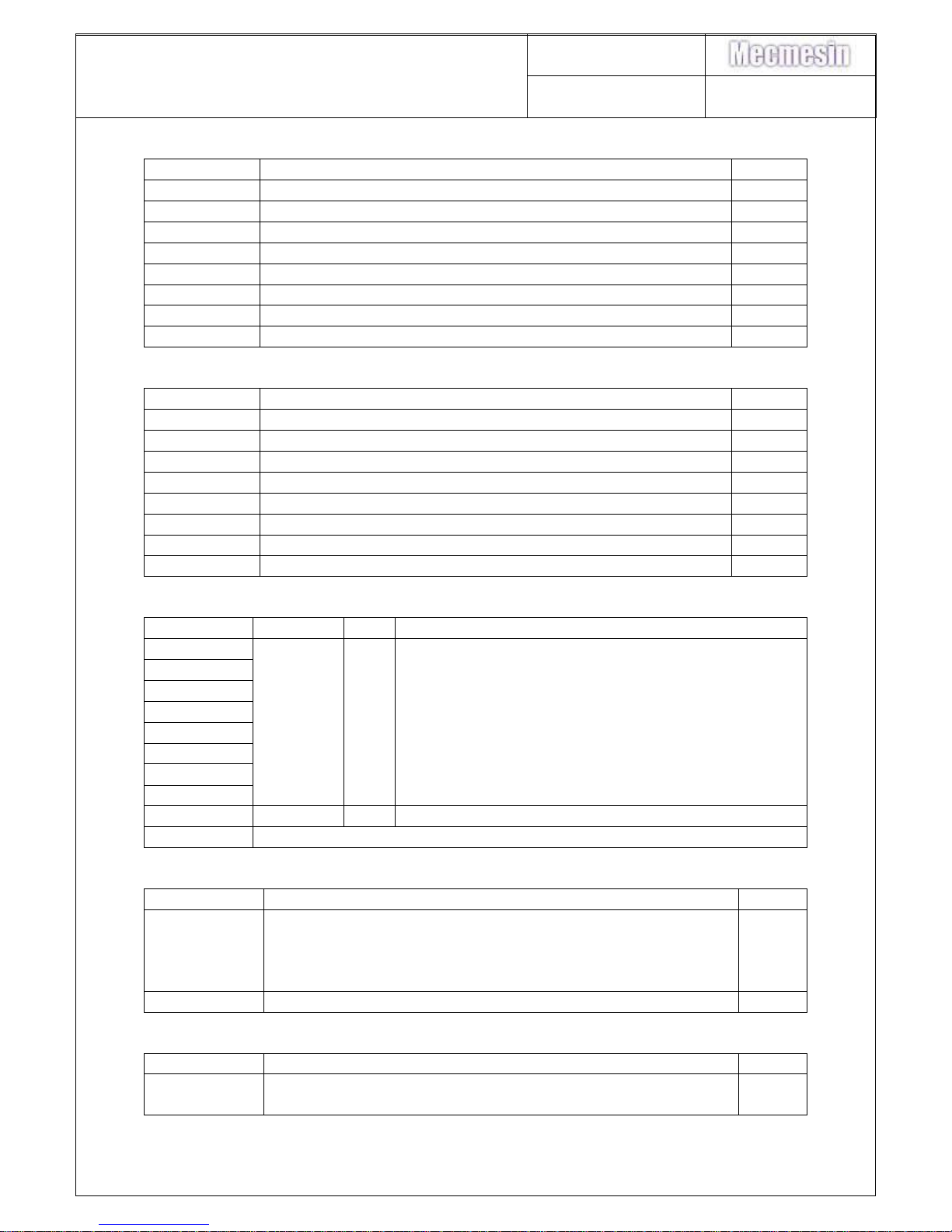
900-296 – 900-301 kits consist of:
P/N
DESCRIPTION
QTY
329-187
4way header 0.1 PI G’plat
1
400-xxx-S01
Load cell – to capacity required
1
406-408
Load cell stud 10/32 UNF
1
410-xxx
AFG Mk4 label to capacity
1
410-xxx
BFG Mk4 label to capacity
1
414-023
Heat shrink black 1.5mm
0.04mtr
420-138
10/32 half nut
1
420-265
Skt cap screw 6-32 UNC x 5/8”
2
900-302 – 900-303 kits consist of:
P/N
DESCRIPTION
QTY
329-187
4way header 0.1 PI G’plat
1
400-xxx-S01
Load cell – to capacity required
1
406-409
Load cell stud 5/16 UNC
1
410-xxx
AFG Mk4 label to capacity
1
410-xxx
BFG Mk4 label to capacity
1
414-023
Heat shrink black 1.5mm
0.04mtr
420-316
¼” half nut
1
420-401
M8 x 23 hex bolt (stainless)
2
China AFG kit
CAPACITY
P/N
QTY
DESCRIPTION
2.5N
900-305
1
CHINA AFG KIT FOR 2.5N - 500N
5N
10N
25N
50N
100N
250N
500N
1000N
900-306
1
CHINA AFG KIT FOR 1000
2500N
No sub-assembly
900-305 kits consist of:
P/N
DESCRIPTION
QTY
900-163
AFG Mk4 case assembly 2.5-500N
(contains
404-161-F11 – AFG Mk4 Battery cover and paint
408-428-F11 – AFG Mk4 2.5-500N Case and paint)
1
(1)
(1)
900-293
China AFG common parts
1
900-306 kits consist of:
P/N
DESCRIPTION
QTY
900-164
AFG Mk4 case assembly 1000 par M8
(contains
1
Page 44
AFG/AFTI Mk 4
Service and Repair Manual
Number 022-614
Issue Number: 09
Page 44 of 47
404-161-F11 – AFG Mk4 Battery cover and paint
408-427-F11 – AFG Mk4 1000N 2500N Case and paint)
(1)
(1)
900-293
China AFG common parts
1
900-293 kit consists of all the ‘common’ parts to make up the AFGs.
28. Exploded parts diagram
Page 45
AFG/AFTI Mk 4
Service and Repair Manual
Number 022-614
Issue Number: 09
Page 45 of 47
Page 46
AFG/AFTI Mk 4
Service and Repair Manual
Number 022-614
Issue Number: 09
Page 46 of 47
29. Changes to 300-157-V03
Part No.
Description
Qty
300-157-V03
AFG PCB Analogue cal.
1
311-012
402 Ohm resistor 10ppm
1
315-505
200 Ohm pot trimmer 13 turn 100ppm
1
311-104
1k Ohm resistor 10ppm
1
1. Replace VR2 with 200 Ohm pot trimmer 13 turn 100ppm (315-505).
Page 47
AFG/AFTI Mk 4
Service and Repair Manual
Number 022-614
Issue Number: 09
Page 47 of 47
2. Replace R63 with 1k Ohm resistor 10ppm (311-104) and R64 with 402 Ohm
resistor 10ppm (311-012).
 Loading...