

Page 1
Operating Manual
F
orce
G
auge
F
orce
G
auge
Advanced
Advanced
Page 2

Page 3

page 1
Contents
Powering the Gauge 2
Using the Gauge 3
Basic Functions 5
Optional Settings 9
Additional Force & Torque Sensors 10
Advanced Menu Options 11
AFG Specifications 26
Introduction
Thank you for choosing the Mecmesin Advanced Force Gauge (AFG) instrument. With correct
use and regular re-calibration it will give many years of accurate and reliable service.
The Mecmesin AFG is the flagship member of a series of highly versatile display units. By using
the latest integrated circuit technology it has been possible to produce an instrument which can
be used to measure tensile and compressive forces accurately, whilst being simple to use by the
operator. Information contained in this operating manual also applies to the AFTI display when
used with external ‘Smart’ sensors.
Before Use
Upon receiving the unit please check that no physical damage has occurred to the packaging
material, plastic case or the instrument itself. If any damage is evident please notify Mecmesin
immediately.
Operation
The most commonly used features (such as displaying force, peak hold, zero and changing of
displayed units) can all be done by pressing a single dedicated key identified on the front
panel with grey text – see page 5, Basic Functions.
For less frequently used features, a number of menu “hot keys” are provided, whereby the
operator simply presses and holds a menu key to access the gauge configuration – see page
9, Optional Settings.
To configure the advanced features of the gauge a full menu-driven system is available by using
the keys identified on the front panel with red text – see page 11, Advanced Menu Options.
Page 4
page 2
POWERING THE
GAUGE
Fitting and charging of
rechargeable batteries
Low Battery Warning
Mains operation
The AFG is supplied with a set of 5 Nickel Metal Hydride
AAA rechargeable batteries. For safety reasons during
transportation the batteries are shipped discharged. To obtain
maximum battery life we recommend that you charge them
with the charger/adaptor supplied for at least 14 - 16 hours
when you first receive the AFG.
To insert the batteries you must first remove the battery cover
on the upper part of the rear of the gauge by undoing the 3
retaining screws. Fit the 5 batteries in the battery holder
ensuring that you observe polarity and the batteries are
placed on top of the ‘release tag’.
To remove the batteries simply pull the ‘release tag’ and they
will be freed from the spring-loaded contacts.
Refit the battery cover and tighten the 3 retaining screws.
Connect the mains adaptor/charger to the AFG charger
socket located at the right hand side of the gauge next to the
display and charge the batteries for 14 - 16 hours. Only use
the adaptor/charger supplied. A fully charged battery pack
will provide approximately 20 hours use between charges.
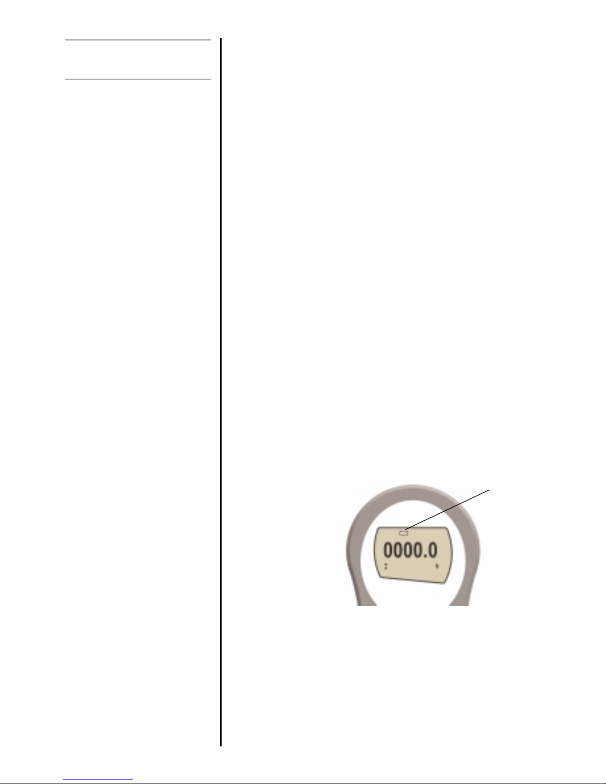
A low battery symbol will appear in the display
approximately 2 minutes before the gauge powers down
automatically. See fig. 1a
The AFG can also be powered directly from the mains. This
can be achieved with or without the rechargeable batteries
being fitted. Connect the mains adaptor/charger to your
mains supply. Only use the adaptor/charger supplied.
Fig.1a
Low battery
warning
Page 5

Fitting of alkaline batteries
USING THE GAUGE
Fitting accessories
Note: When fitting a grip ensure
that it is screwed finger-tight only.
Excessive torque can damage
the load cell.
Mounting to a test stand
If rechargeable batteries are fitted, a trickle charge will be
applied to the batteries.
The AFG can also be powered by AAA 1.5V alkaline
batteries (not supplied). For the fitting of alkaline batteries,
follow fitting instructions as per rechargeable batteries above.
Warning: When alkaline batteries are fitted, the mains
adaptor/charger must NEVER be connected to the AFG due
to the risk of acid leakage which could damage the
instrument.
The Rotary Coupling is supplied with AFG instruments
between capacities of 10N to 1000N. It allows operators to
orientate the gripping accessory without the need for a
locking wheel (as on the extension rod).
We do not recommend it to be used for AFG 2.5N and 5N
due to its weight, which would need to be tared from the
measuring range.
Affix the Rotar y Coupling to the male thread of either the short
extension rod (30mm long) or the long extension rod (130mm
long). Affix the extension rod to the load cell probe in the
hole at the bottom of the gauge by tightening it gently with
the fingers.
Your chosen grip or accessory may now be connected to the
rotary coupling.
On the rear of the gauge there are two M5 threaded holes,
which can be used for mounting the gauge to a Mecmesin
test stand.
Each Mecmesin test stand is supplied with a dedicated
‘dovetailed mounting bracket’ and screws for this purpose.
If you wish to mount to another type of stand, ensure that the
screws used are threaded into the gauge to a maximum
depth of 5.5mm. The final thread is peaned but if screws are
fitted beyond this depth, damage to the internal PCB may
occur.
page 3
Page 6
page 4
Powering up
Please note that an AFG
measuring very low forces may
not show zero if it is moved
during the self test routine. Once
it is properly mounted and
zeroed the reading will be stable
NB: All the current settings are
saved when the gauge is turned
off and the gauge will function in
the same mode when powered
up again.
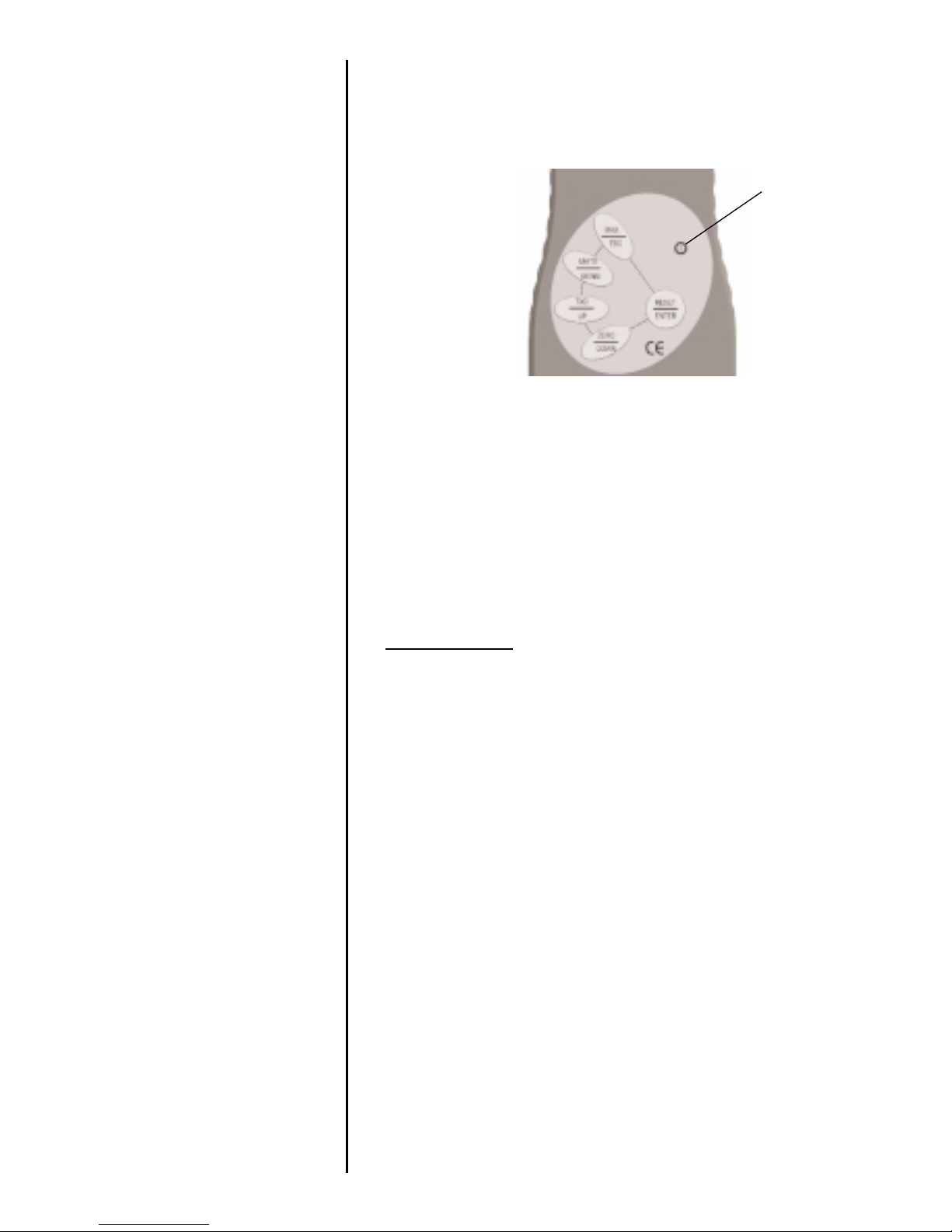
As shown in Figure 1b the control panel has 6 keys:-
To power up the
gauge press the
red key. A
short self test runs
during which the
display will show
the model and
capacity in
Newton’s.
After the self test, providing no load has been applied to the
instrument, the display will show all zeroes. This is because
the gauge re-zeroes itself during the self test routine.
If a force is applied perpendicularly via the sensor probe
(hole at bottom of AFG), the reading on the display will
register the applied force.
* Do not overload
the transducer, as this will cause
irreparable damage.
Forces greater than 120% of full-scale will produce an
audible beep until load is released and an OL symbol will
appear on the display for 30 seconds.
Forces greater than 150% of full-scale will produce an
audible beep until load is released and an OL symbol will
appear permanently on the display. Consult your supplier to
arrange repair.
To power down the gauge press the red key.
b
Fig.1b
b
Power On/Off
key
Page 7
page 5
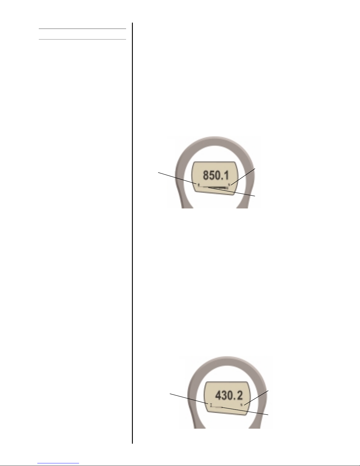
Tensile forces are displayed on the AFG and recognised by
the symbol
Compressive forces are displayed on the AFG and
recognised by the symbol
A load indicator bar alerts the operator to how much load
has been applied to the transducer. As the load approaches
the maximum rating of the transducer, the indicator bar
changes appearance when above approx. 80% of the rated
capacity. This warns the operator that steps should be taken
to prevent excessive load being applied.
For tensile forces the indicator bar is solid then dotted. For
compressive forces the indicator bar is dotted then solid – see
Figure 2b.
Fig. 2a
Symbol for
tension
Unit of
measurement
Load indicator bar
Basic Functions
Display of Tension/
Compression
If the AFG has suffered a serious
overload condition, the load
indicator bar will be partially
displayed even when no load is
present. This is a warning that
the load cell is damaged and
you should immediately contact
your supplier to arrange repair.
Fig. 2b
Symbol for
compression
Unit of
measurement
Load indicator bar
Page 8

page 6
Zeroing the Gauge
Changing the unit of
measurement
Max (peak) readings
"Max" mode
During the operation of the gauge it is often necessary to
zero the display – e.g. when you wish to tare out the weight
of a grip, so it does not become part of the measured
reading. Press and release the ZERO key. The display will
blink momentarily as the zero operation is carried out.
You can choose from the following units of measurement
depending on the capacity of your gauge: milliNewtons,
kiloNewtons, Newtons, gram-force, kilogram-force, ounceforce or pound-force.
To change the display units press and release the UNITS key.
Each successive key press will select the next available units
until the gauge returns to its original setting. The AFG
automatically converts readings as new units of measure are
selected.
The gauge detects and stores maximum (peak) force in both
compressive and tensile directions.
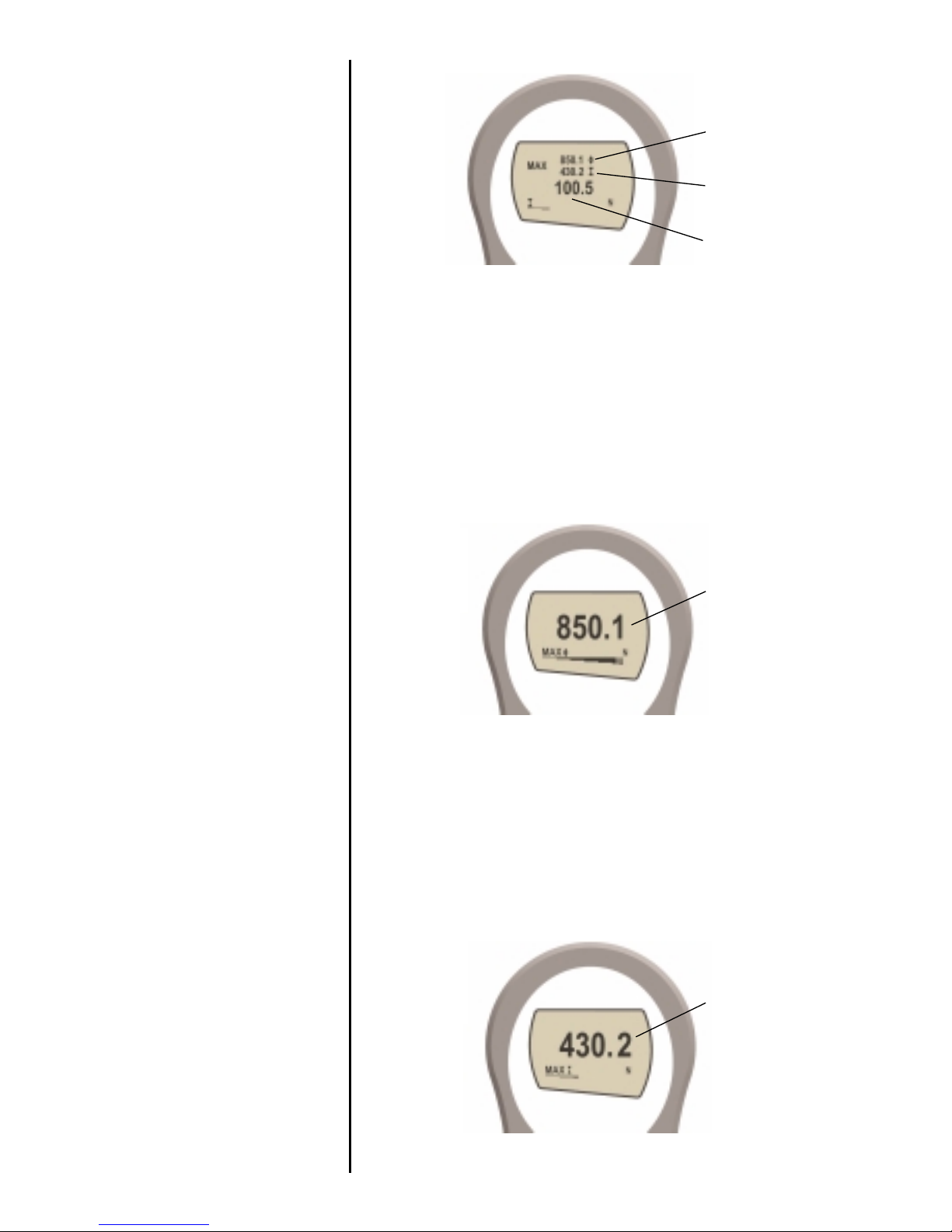
Press the MAX key. The display will show the word MAX
together with the highest tensile force and the highest
compressive force detected during the test. The current
load being applied to the transducer is also displayed -
see Figure 3a overleaf.
Page 9
page 7
Press the MAX key again and the display will show the
maximum tensile force identified by the symbol.
Press the MAX key again and the display will show the
maximum compressive force identified by the symbol.
Fig. 3c
max compression
reading
Fig. 3b
max tension
reading
Fig. 3a
max tension
reading
max compression
reading
Load currently
applied to load
cell
Dual Max
Max Tension
Max Compression
Page 10
page 8
Press the MAX key again and the word MAX has now
disappeared from the display. The display will now indicate
forces applied in both directions as they are applied to the
transducer and maintain a "running" display.
Press the RESET key to clear both maximum registers and
prepare for detecting the next maximum readings.
(See also COMMS section of Advanced Menu Options on page 23)
A calibrated analogue output is available from the top ‘D
type’ connector for use with chart recorders, oscilloscopes or
any other devices requiring analogue inputs. See technical
specifications on page 26 and 30 for details.
It is possible to transmit the displayed reading to peripheral
devices (e.g. PC, printer) by pressing and releasing the TXD
key.
Displayed readings can also be requested individually from a
PC via the RS232 interface by sending a"?" (ascii D63 [3fh]
character.
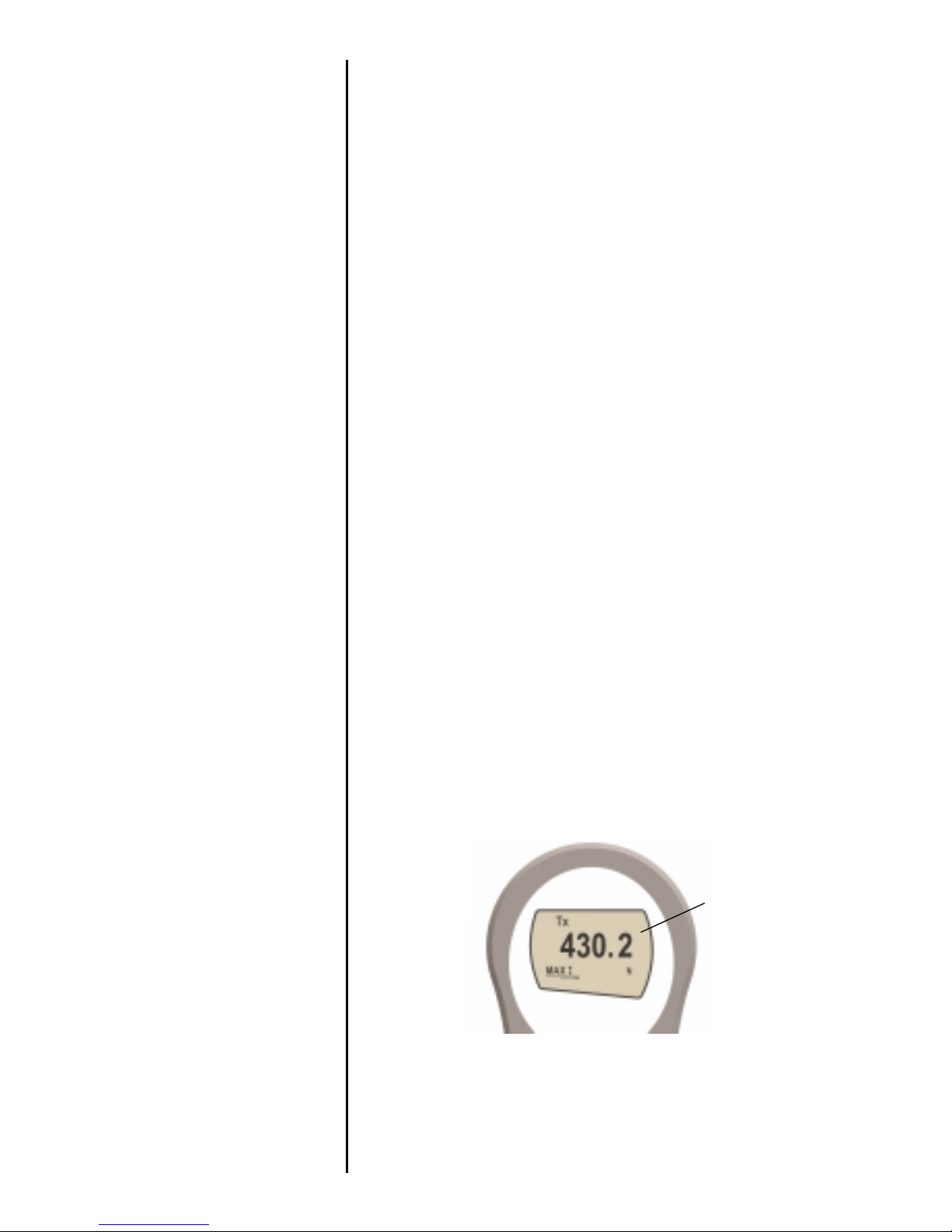
For sending a continuous data stream to a PC, press and
hold the TXD key for 2 seconds then release. TX will now
appear in the display to indicate that data is being sent. To
stop sending data, simply press and release the TXD key, at
which point TX will disappear from the display.
Please note that the continuous data stream only starts when
approx. 2% of the rated capacity of the gauge is reached.
"Normal" mode
Data Output
Analogue output
RS232 and Mitutoyo
output signals
PC Communication
AFG uses 9600, 19200,
57600 or 115200 Baud, 8
data bits, 1 start bit, 1 stop bit
and no parity.
(See Advanced
Menu Options for setup details)
A full range of data cables are
available to connect your gauge
to peripheral devices – contact
your supplier.
Fig. 4
max compression
reading
Page 11

page 9
It is possible to activate a backlight on the AFG display.
Press and hold UNITS whilst powering up the AFG with the
key. The backlight is now operating.
Please note that battery consumption is doubled when using
the backlight. For this reason the backlight setting is not
remembered after power down.
To conser ve batter y power, it is possible to activate an Autooff function so that the gauge powers down after 2 minutes
since the last key press.
Press and hold ZERO whilst powering up the AFG with the
key. The symbol ‘Ao’ will appear in the display to
indicate Auto-off is active. This feature is remembered after
power down.
For tension applications it is often desirable to reverse the
display, so that the operator can read it more comfor tably.
Press and hold the MAX key whilst powering up the AFG with
the key to invert the display. This feature is remembered
after power down.
The AFG may be returned to its original factory default
settings, indicated on pages 28 and 29 of the Advanced
Menu Options section of this manual.
Press and hold the RESET key whilst powering up the AFG
with the key
Optional Settings
Backlit
Display
Auto-off
Invert Display
Factory Default
b
b
b
b
Page 12
The AFG has an interchangeable loadcell cartridge, which
allows selection of different capacity load cells to be fitted to
the AFG console.
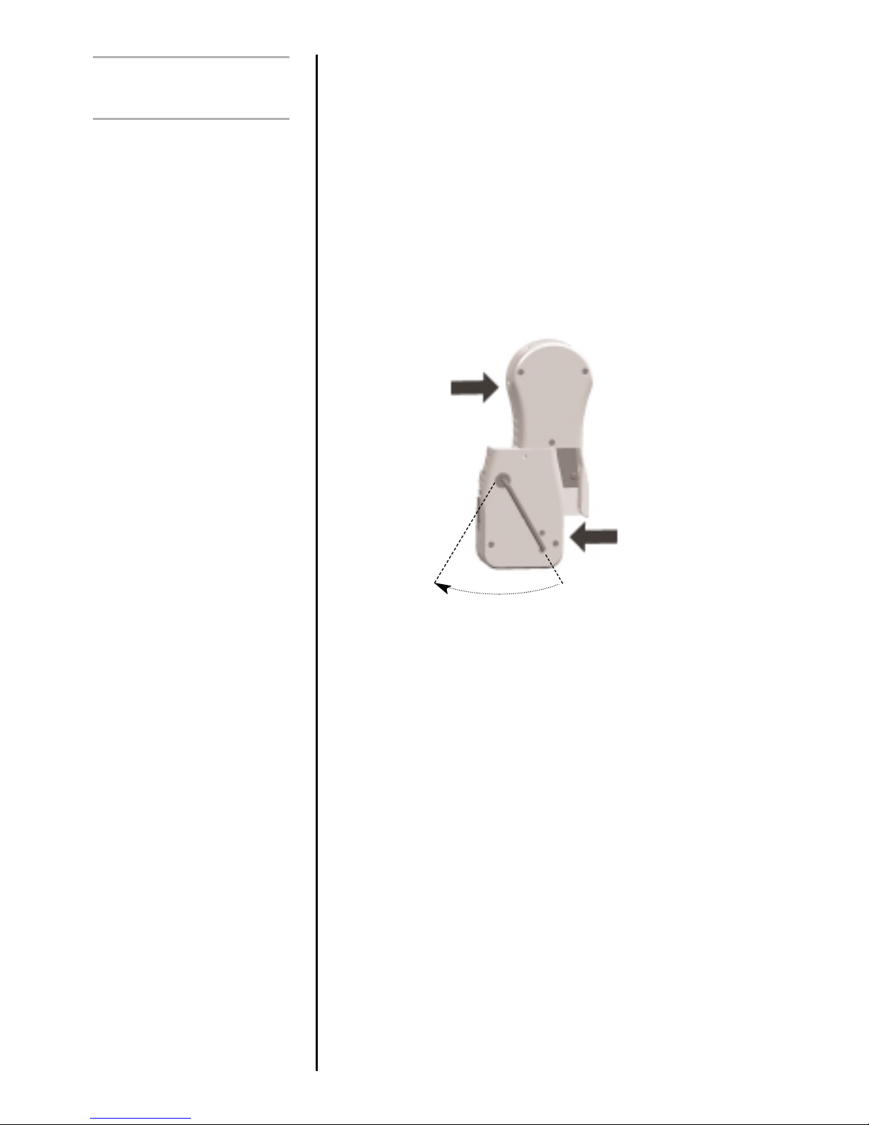
To exchange the cartridge, power down the gauge and
remove it from the test stand if it is fitted to one.
Turn the gauge face down and inser t a 4mm Allen key
(supplied) into the boss on the back of the ALC.
To unlock the ALC rotate the boss anti-clockwise with the Allen
key through approximately 30º to release the spring loaded
locking cam. Whilst still holding the Allen key in position slide
the ALC away from the AFG console to the left. See Figure 5.
To fit the new ALC, first insert the Allen key into its boss and
rotate the locking cam as above. Slide the ALC into the AFG
console, ensuring that the mating surfaces are correctly
aligned.
Push the ALC firmly home into the AFG console and, to lock
it, tighten the locking cam by rotating the Allen key clockwise
until slight pressure is felt. Take care not to over tighten the
locking cam.
All Advanced Loadcell Cartridges have a 15-pin ‘Smart’
connector port on the right hand side for interface with
Mecmesin external ‘Smart’ force and torque sensors. This
allows you to use your existing AFG console to perform
additional tests without the need for a dedicated instrument.
To connect a ‘Smart’ sensor, power down the gauge and
plug in the ‘Smart’ force or torque sensor to the 15-pin ‘Smart’
port. Power on the AFG. The ‘Smart’ transducer will be
automatically recognised and the capacity displayed.
page 10
Additional Force &
Torque Sensors
Interchangeable Advanced
Loadcell Cartridges (ALC)’s
Warning! Incorrect alignment
of the ALC may lead to
damage to the ALC interface
pins.
‘Smart’ sensors
Warning! The AFG must be
powered down when
connecting or disconnecting
smart transducers.
Note: Connecting a new
‘Smart’ transducer causes the
default settings within
Advanced Menu Options to
be installed
30˚
Fig. 5
Page 13
page 11
If you suspect that your ALC loadcell or ‘Smart’ sensor has
sustained an overload it is possible to check the status of the
sensor immediately.
Symptoms of overload may be (a) OL in display (b) buzzer
sound (c) probe not aligned perpendicularly to gauge (d)
load indicator bar present even under zero load.
See CALIBRATION section of Advanced Menu Options on
page 24 to check load cell status.
All the features and advanced menu options of the AFG are
also applicable whilst using the ‘Smart’ range of peripheral
devices.
The AFG Advanced Menus are accessed using the red text
on the keys.
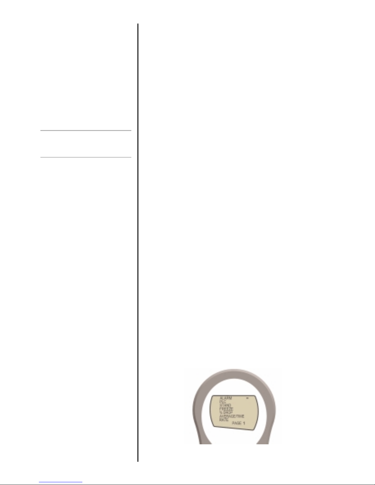
Press and hold the MENU key for approximately 2 seconds to
access page 1 of the main-menu. To move between the
options listed on the 2 main-menu pages, press UP and
DOWN to move the cursor. Press ENTER to select sub-menus,
activate features and enter values. Within sub-menus UP and
DOWN will also change numerical values. Press ESC to
return to page 1 of the main-menu page.
If ALARM is selected in page 1, by pressing ENTER the status
of all the other functions can be seen by consecutively
pressing the MENU key to scroll through the functions one at
a time. Press ESC once to return to the main menu page and
twice to return to the main display.
Loadcell Diagnostic test
An instrument showing an
overload condition cannot be
relied upon to provide accurate,
repeatable measurement –
consult your supplier.
Advanced Menu
Options
Navigating the menus
Fig. 6
MAIN MENU
PAGE 1
Page 14
page 12
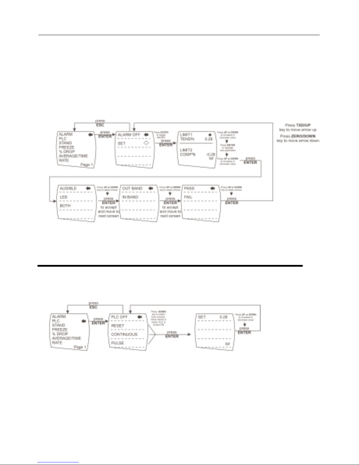
The AFG has an audible and visual alarm feature which can
be set to trigger on pass, fail or sample break criteria.
To set an alarm, press and hold the MENU key until page 1
of the main-menu appears.
The cursor arrow will point to ALARM. Press the ENTER key.
The display will show ALARM OFF and SET.
Press ENTER to change ALARM OFF to ALARM ON.
Press DOWN to move the arrow cursor to SET and press
ENTER.
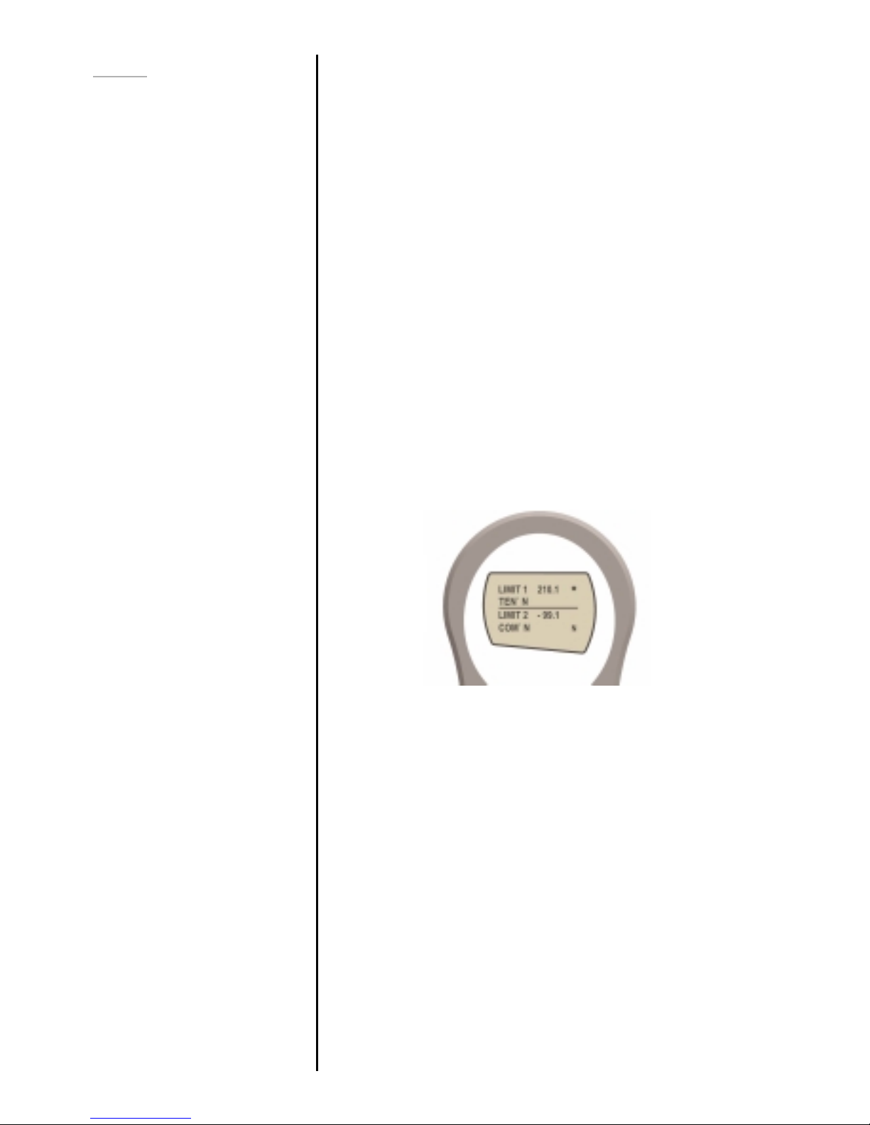
The display will now show the two limits LIMIT 1 (lower limit)
and LIMIT 2 (upper limit) plus the value they are set to and
whether they are in tension (TENS’N) or compression
(COMP’N). A diamond cursor will indicate which value is
selected. Use UP and DOWN keys to change the value,
press and hold to scroll values. When the correct value is
reached press ENTER to set LIMIT 1. Repeat procedure for
LIMIT 2.
Note: The alarm limits are not active below 1% of the
capacity of the gauge.
The display shows AUDIBLE, LED and BOTH with the arrow
cursor indicating which feature is selected. This menu selects
how the PASS/FAIL status of a value will be indicated.
AUDIBLE - Only the audible alar m will be activated when
the value is a PASS/FAIL.
LED - The green and red LED’s will indicate the PASS
/FAIL status.
BOTH - Both the LED and the audible alarm will be
activated above.
Use UP and DOWN to move the cursor and press ENTER to
select the desired feature.
ALARM
ALARM sub-menu 1
ALARM sub-menu 2
Torque sensors will show
CW for clockwise and
CCW for counter-
clockwise
ALARM sub-menu 3
Fig. 7
Page 15
page 13
The display shows OUT BAND and IN BAND. This menu
selects which values are to be considered.
OUT BAND - Any value falling outside the set limits
LIMIT 1 and LIMIT 2
IN BAND - Any value falling between the set limits LIMIT 1
and LIMIT 2
Use UP and DOWN to move the cursor and press ENTER to
select the desired feature.
The display shows PASS, FAIL and PULSE. This menu sets the
OUT BAND and IN BAND mode.
PASS - Values, which fall either OUT BAND (or IN BAND,
if selected), are a PASS and will cause an audible
beep
FAIL - Values, which fall either OUT BAND (or IN BAND,
if selected), are a FAIL and will cause an audible
beep
Use UP and DOWN to move the cursor and press ENTER to
select the desired feature.
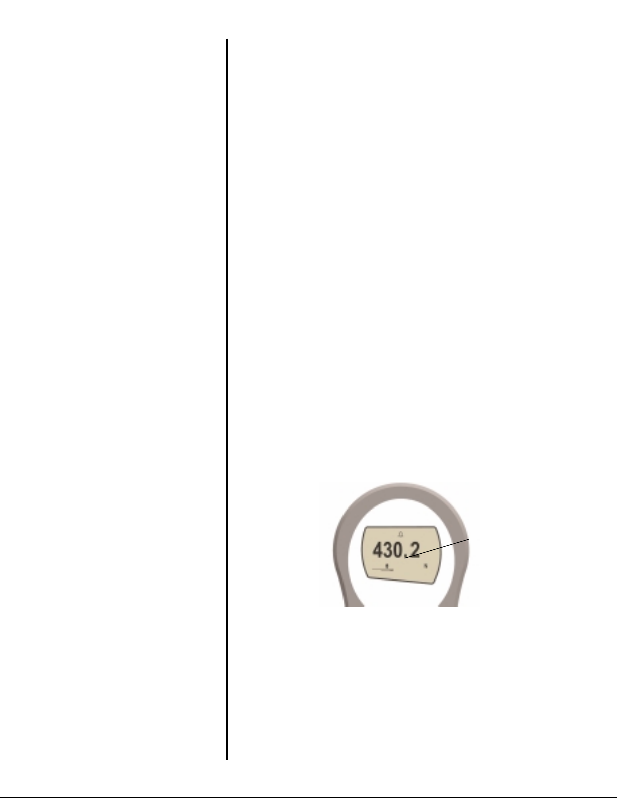
Display is showing sub-menu 1 again (= ALARM ON and
SET). Press ESC to return to main-menu and again to return to
main display. The main display will now show an alar m
‘bell’ symbol indicating the alarm is turned on. See Figure 8.
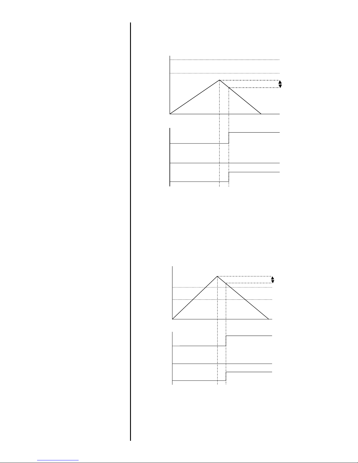
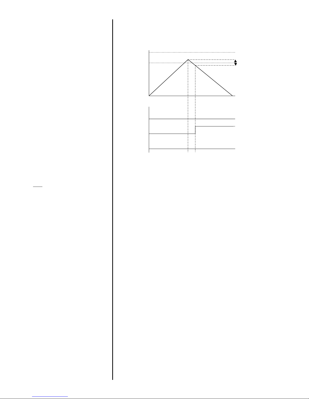
This feature is only activated when the % DROP feature is
used in conjunction with the ALARM function. The AFG looks
for a percentage (of full-scale) drop from peak load value, set
in the % DROP menu (see page 19). The alarm can be used
to indicate if the break point falls inside or outside the limits
LIMIT 1 and LIMIT 2 set in the alarm menu (see Examples 1 to
5 overleaf).
ALARM sub-menu 4
ALARM sub-menu 5
ALARM on break
Fig. 8
alarm symbol
Page 16
page 14
Example 1
Settings: -
- BOTH LED and audio
alarms are active
- Alarm triggers on OUT
BAND
- Alarm is set to FAIL
- % DROP is 10% of fullscale (e.g. AFG 100N
must register drop of 10N)
Main display is set to 1st
peak tension screen
Example 2
Settings: -
- BOTH LED and audio
alarms are active
- Alarm triggers on OUT
BAND
- Alarm is set to FAIL
- % DROP is 10% of fullscale (e.g. AFG 100N
must register drop of 10N)
Main display is set to 1st
peak tension screen
Example 1
UPPER LIMIT
LOWER LIMIT
LOAD
TIME
10% DROP
RED LED
GREEN LED
BEEP
ON
OFF
ON
ON
OFF
OFF
Example 2
UPPER LIMIT
LOWER LIMIT
LOAD
TIME
10% DROP
RED LED
GREEN LED
BEEP
ON
OFF
ON
ON
OFF
OFF
Page 17
page 15
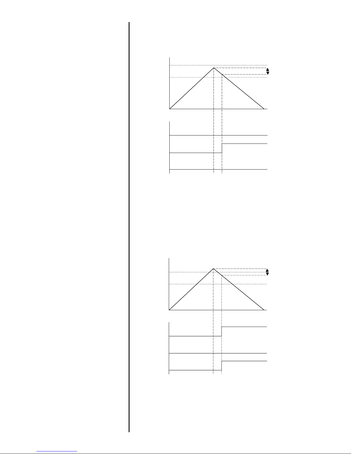
Example 3
Settings: -
- BOTH LED and audio alarms
are active
- Alarm triggers on OUT
BAND
- Alarm is set to FAIL
- % DROP is 10% of full-scale
(e.g. AFG 100N must
register drop of 10N)
Main display is set to 1st
peak tension screen
Example 4
Settings: -
- BOTH LED and audio alarms
are active
- Alarm triggers on OUT
BAND
- Alarm is set to FAIL
- % DROP is 10% of full-scale
(e.g. AFG 100N must
register drop of 10N)
Main display is set to 1st
peak tension screen
Example 3
UPPER LIMIT
LOWER LIMIT
LOAD
TIME
10% DROP
RED LED
GREEN LED
BEEP
ON
OFF
ON
ON
OFF
OFF
Example 4
UPPER LIMIT
LOWER LIMIT
LOAD
TIME
10% DROP
RED LED
GREEN LED
BEEP
ON
OFF
ON
ON
OFF
OFF
Page 18
page 16
The AFG has a load output signal which may be used for
PLC applications. This function requires an external cable
with a built-in solid-state relay – see Specifications on pages
26 and 27 for details of the signal.
To configure the signal output from the AFG, press and hold
the MENU key until page 1 of the main-menu appears. Press
DOWN to move the arrow cursor to PLC and press the
ENTER key. The cursor arrow now points to PLC OFF.
The display will show:-
PLC OFF - Indicates PLC function status.
RESET - When the load limit is reached, the output
signal triggers the relay and the RESET key
must be pressed to clear the line before
starting the next test.
CONTINUOUS - The relay will be activated every time the
load limit is reached and the output signal
will remain on.
Example 5
Settings: -
- BOTH LED and audio
alarms are active
- Alarm triggers on OUT
BAND
- Alarm is set to FAIL
- % DROP is 10% of fullscale (e.g. AFG 100N
must register drop of 10N)
Main display is set to 1st
peak tension screen
PLC
(Programmable Limit
Controller)
PLC sub-menu 1
Example 5
UPPER LIMIT
LOWER LIMIT
LOAD
TIME
10% DROP
RED LED
GREEN LED
BEEP
ON
OFF
ON
ON
OFF
OFF
Page 19

page 17
PULSE - The relay will be activated momentarily
when the load limit is reached.
Select the desired function and press the ENTER key.
The display will show SET and a default load limit at which
the output signal will trigger the relay.
To set the required load limit use UP and DOWN keys to
adjust the value and ENTER to confirm the selection.
Negative load limits indicate compression.
The display will revert back to PLC sub-menu 1 and PLC ON
will now be displayed.
Press ESC to return to main-menu page 1.
The AFG may be used to send a signal to control the
Mecmesin range of motorised test stands via a dedicated
cable.
To configure the signal output from the AFG, press and hold
the MENU key until page 1 of the main-menu appears. Press
DOWN to move the arrow cursor to STAND and press the
ENTER key.
The display will show:-
STAND OFF - Indicates status of stand control function.
REVERSE - Reverses the stand direction of travel at
sample break (BREAK) or load-limit value
(LIMIT). The test stand will reverse back to
the start position as defined by the
physical Microswitch.
STOP - Stops the stand at sample break (BREAK)
or load-limit value (LIMIT). The test stand
does not return to the start position.
CYCLE - Cycles a suitable test stand between load
limits (UPPER, LOWER) for a set number of
times (CYCLE).
Select the desired function using UP and DOWN keys and
press ENTER to select.
PLC sub-menu 2
STAND
Contact your supplier for stand
interface cable
STAND sub-menu 1
Page 20

page 18
Select UP or DOWN to tell the gauge which direction the
stand will begin to move before the load-limit is reached.
BREAK - Sets the gauge to reverse at sample break. Press
ENTER to select.
SET % of load cell capacity to indicate the value by which the
load must fall to determine a break. Use a higher percentage
for ‘noisy’ samples where the load may fluctuate before the
sample finally breaks.
Press ENTER to confirm selection and return to stand submenu 1.
LIMIT - Sets the load-limit value to trigger the stand reverse
function. Press ENTER to select.
SET load-limit using UP and DOWN keys. (UNITS key
changes the units of measurement for load-limit value). Press
ENTER to confirm selection and return to stand sub-menu.
Negative load limits indicate compression.
Select BREAK or LIMIT as per Reverse sub-menu 2 (above)
and SET the appropriate value at which you require the test
stand to stop.
Select and SET UPPER load-limit, LOWER load-limit and the
number of CYCLES you wish to perform (range = 2 - 9999).
Start the test by pushing the UP or DOWN switch on your test
stand. The test stand will move to the UPPER load-limit and
then travel back to the LOWER load-limit to perform the first
cycle. Subsequent cycles will be performed and a cyclecounter is shown on the main display.
Note:
a) It is assumed that starting a test in the UP direction
applies a tension force, and in the DOWN direction a
compression force is applied.
b) The total number of cycles must be completed .. e.g. if a
sample breaks during the test, the AFG will try to continue
applying load for the set number of cycles.
c) At the end of your cycle test, the test sample will still be
under load.
When one of the stand control options (REVERSE, STOP or
CYCLE) have been set press ENTER. The display will revert
REVERSE sub-menu 1
REVERSE sub-menu 2
Break sub-menu 1
Limit sub-menu 1
STOP sub-menu 1
CYCLE sub-menu 1
Page 21
page 19
back to STAND sub-menu 1 and STAND ON will now be
displayed. Press ESC to return to main-menu page 1.
This feature is used to ‘freeze’ the main-display when an
external signal is received. The AFG can be configured to
freeze when going either low 1-0 (LO) or high 0-1 (HI). This
is particularly useful for applications where an event occurs
(e.g. switch testing). To clear the main-menu display press
RESET.
To configure this function, press and hold the MENU key until
page 1 of the main-menu appears. Press DOWN to move the
arrow cursor to FREEZE and press the ENTER key.
Select the desired LO or HI function using UP or DOWN
arrow keys and press ENTER to select. When set the submenu will display FREEZE ON. To disable the FREEZE
function, press ENTER. FREEZE OFF will now be displayed.
Press ESC to return to main-menu page 1.
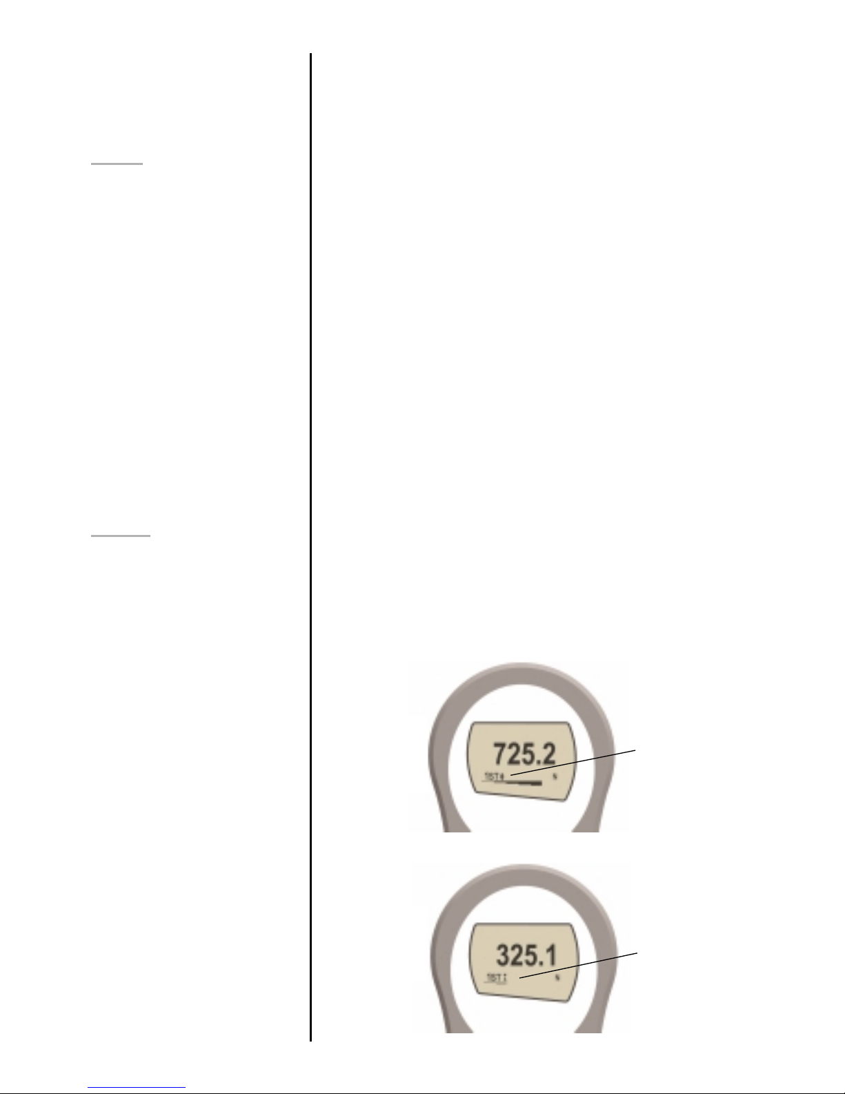
1st Peak facility – this is used to detect the force at which a
sample breaks but is not necessarily the maximum force (e.g.
detecting the force at which a tablet first begins to crack..)
When this feature is set to ON, two additional functions can
be selected using the MAX key from the main display.
Note: It is recommended to
press RESET after each
STAND operation
FREEZE
Contact your supplier for
interface cable
.
FREEZE sub-menu 1
% DROP
1st Peak Tension
1st Peak Compression
Fig. 10
1st peak
compression
symbol
Fig. 9
1st peak tension
symbol
Page 22
page 20
% drop set to 20%
1st Peak
Tension/Compression
% DROP sub-menu 1
% DROP sub-menu 2
EXAMPLE
This test would produce a
first peak result
Fig. 11
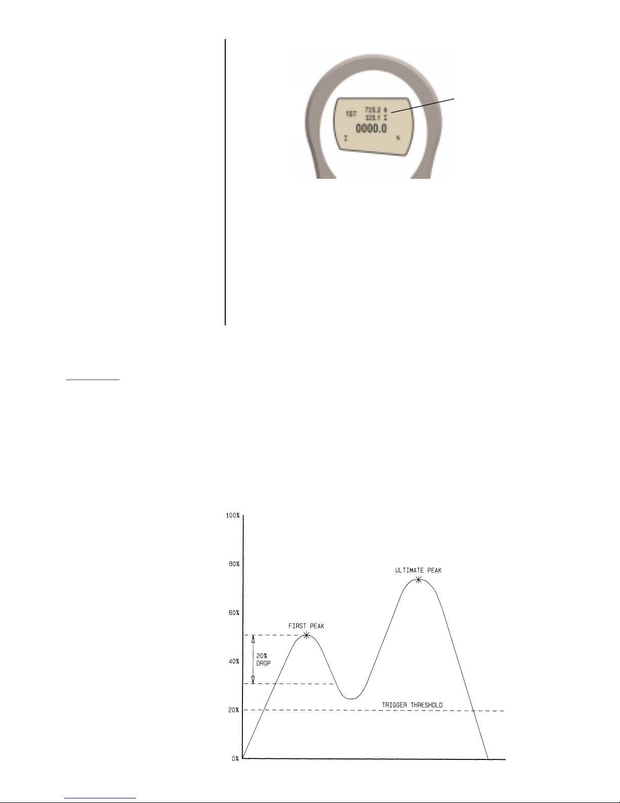
The dual Max
display now shows
1st peak tension
and 1st peak
compression. Load
currently applied to
instrument is also
shown (0000.0)
The display will show % DROP OFF and SET.
Press ENTER to
change % DROP OFF to % DROP ON. Press DOWN to move
the arrow cursor to SET % and press ENTER.
To determine what precisely is considered a break, you must
define the % drop of full-scale value from the peak load
observed prior to the break occurring.
To set the required % drop use UP and DOWN keys to adjust
the value and press ENTER to confirm the selection.
The % drop value selected also acts as a threshold, below
which the % drop function will not be active.
Example: AFG 100N has % drop of 20 (= 20N). If the peak load
before sample break is 50N, the load must drop to 30N in order for
the AFG to detect a 1st peak of 50N. If load continues to be
applied above 50N (e.g. to 75N), the AFG will return 75N as MAX
and 50N as 1st peak.
Page 23
page 21
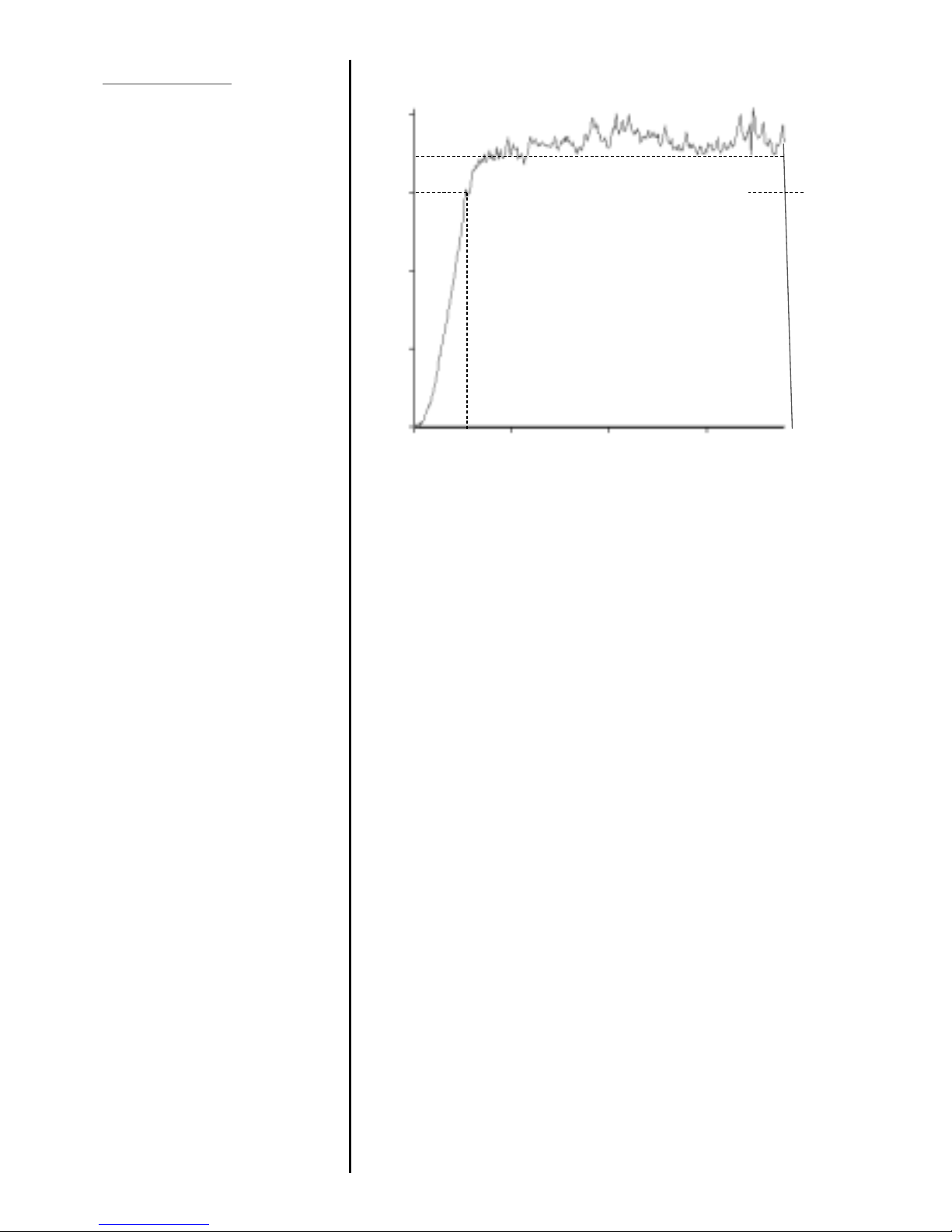
This function allows the average load reading to be
displayed. The average starts being calculated when the
threshold (% of full-scale) is reached and stops being
calculated when the load falls back below this threshold.
To set AVERAGE over TIME, press and hold the MENU key
until page 1 of the main-menu appears. Using UP and
DOWN move the cursor key to AV/TIME. Press the ENTER
key.
The display will show AVERAGE/TIME OFF and SET.
Press ENTER to change AVERAGE/TIME OFF to AVERAGE
/TIME ON. Press DOWN to move the arrow cursor to SET
and press ENTER.
Define a % value of full-scale as the threshold value in the SET
T menu. Any load reading above this threshold will be
averaged over time with all the previous readings occurring
since the threshold value was exceeded. Averaging stops
when load readings fall back below the threshold.
Press ESC to return to main-menu page 1.
AVERAGE/TIME
Avg/Time sub-menu 1
Avg/Time sub-menu 2
25N
100N
75N
50N
0
Start Threshold
x Peak
TIME
Stop Threshold
Average
Page 24
page 22
This function allows the selection of the gauge throughput
rate, i.e. the amount of averaging performed by the internal
electronics before the load reading is displayed. There are
three levels HI, MED and LO.
HI - Display updates quickly with little data
averaging
MED - Gauge default.
LO - Maximum data averaging before values are
displayed. Smoothes ‘noisy’ data.
To set RATE, press and hold the MENU key until page 1 of
the main-menu appears. Using UP and DOWN move the
arrow key to RATE.
Using UP and DOWN select the relevant level (HI, MED or
LO) and press the ENTER key.
Press ESC to return to page 1 of the main-menu.
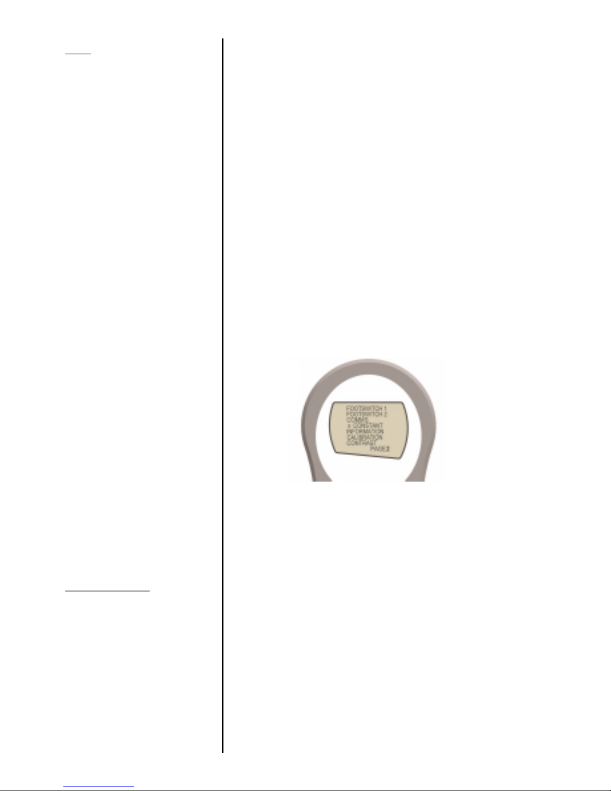
MAIN-MENU PAGE 2
From page 1 of main-menu press MENU to scroll to page 2
of the main-menu.
The AFG has two footswitch input pins on the 15-way D
connector. This allows the footswitch to be assigned to
replicate one of each of the five main key functions, MAX,
UNITS, TXD, ZERO and RESET.
This feature is useful when integrating the AFG into test or
production systems.
To assign the function of a key to FOOTSWITCH 1 use UP
and DOWN to move the arrow key to FOOTSWITCH 1.
Using UP and DOWN select the relevant key (MAX, UNITS,
TXD, ZERO or RESET) and press the ENTER key.
Press ESC to return to page 2 of the main-menu.
RATE
FOOTSWITCH 1
Fig. 12
Page 25

page 23
To assign the function of a key to FOOTSWITCH 2 use UP
and DOWN to move the arrow key to FOOTSWITCH 2.
Using UP and DOWN select the relevant key (MAX, UNITS,
TXD, ZERO or RESET) and press the ENTER key.
Press ESC to return to page 2 of the main-menu.
Communications settings are selected to configure interfacing
of the AFG with peripheral devices. Also used to configure
the AFG to store up to a maximum of 100 readings in the
internal memory.
To set communications first use UP and DOWN keys to move
the cursor arrow to COMMS on page 2 of the main-menu.
Using UP and DOWN select the relevant option (see below)
and press the ENTER key.
PORT - Communicates with peripheral device.
Transmission of the displayed load reading
can be set to include unit of measurement
(UNITS ON or OFF) and BAUD rate can
also be set.
STORE MEM - Stores a single load reading to the internal
memory. With this option selected, pressing
the TXD key when in the MAX modes of the
main display will send the displayed value to
memory. Up to 100 readings may be stored
in the memory. As each reading is stored, a
‘REC’ symbol appears on the main display
to indicate a reading has been stored in the
memory.
SEND MEM - Sends all load readings stored in the internal
memory to a peripheral device (e.g PC or
data logger).
CLEAR MEM – Erases all load readings stored in memory.
When setting PORT you will now access sub-menu 1.
Transmission of the displayed load reading can be set to
include the unit of measurement (UNITS ON or OFF).
Use the UP or DOWN key to position the arrow cursor at
either UNITS OFF or ON. Press ENTER to select.
FOOTSWITCH 2
COMMS
COMMS sub-menu 1
Port sub-menu 1
Page 26

page 24
The transmission (or Baud) rate can now be set.
Use the UP or DOWN key to position the arrow cursor at the
relevant speed (2400, 9600, 57600 or 115200). Press
ENTER to select.
You will now return to page 2 of the main-menu.
To set STORE MEM press ENTER from Comms sub-menu 1.
This will cause a memory counter to appear in the main
display. You will now return to page 2 of the main-menu.
To set SEND MEM press ENTER from Comms sub-menu 1.
This will cause a TX symbol to flash in the main display as the
memory data is now transmitted to a peripheral device. The
data is transmitted at the settings defined by PORT. After
transmission of data you will now return to page 2 of the
main-menu.
To set CLEAR MEM press ENTER from Comms sub-menu 1.
This now erases all the data stored in the memory. The
memory counter is now reset to zero. After clearing the
memory you will now return to page 2 of the main-menu.
A constant of multiplication can be applied to the load values
in the main display. This is useful for applications where you
wish to convert the load reading into a non-standard unit of
measurement e.g. for co-efficient of friction tests.
Press ENTER to select xCONSTANT. Press UP or DOWN to
adjust the constant of multiplication. Press ENTER to confirm.
Displays calibration information.
T - Tension span
C - Compression span
Z - Current zero
G - Gravitational constant
I - True zero at time of calibration
This is for information only and may be required for
diagnostic purposes by your distributor.
Calibration menu - displays a password menu and allows the
user to check for load cell offset if overload is suspected.
Port sub-menu 2
x/CONSTANT
INFORMATION
CALIBRATION
Page 27
page 25
Place the gauge (or your external SMART sensor) horizontally
on a flat level surface. By using UP or DOWN keys Select
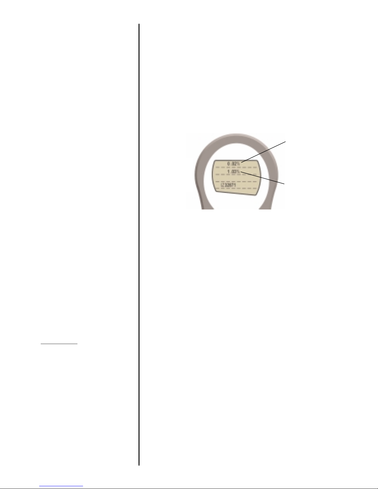
the CAL option and the display will show 0000. Press ENTER
four times (to enter 0000 as the password), a screen showing
initial (at calibration) load cell offsets and current offset in % is
displayed.
The upper value shows the % offset when the gauge was last
successfully calibrated. The lower value shows the % offset
currently present on the gauge. See Figure 13.
If the current % offset is between 5 and 10% please contact
your supplier to arrange a recalibration of your AFG.
If the current % offset is greater than 10% please contact your
supplier to arrange for a load cell replacement. These values
are given as an indicator only – the need for
calibration/repair may vary according to the individual
characteristics of the load cell.
Press and hold ESC until you return to page 2 of main-menu.
The contrast of the display may be increased and decreased
in this menu.
From page 2 of main-menu press UP or DOWN keys to
position the arrow key on CONTRAST. Press ENTER to select
CONTRAST menu and 1.234 will be displayed. Press UP or
DOWN to adjust the contrast of the display and ENTER to
confirm the setting. You will now return to page 2 of the mainmenu
CONTRAST
Fig. 13
upper value =
offset when last
calibrated
lower value =
offset currently
present on gauge
Page 28
page 26
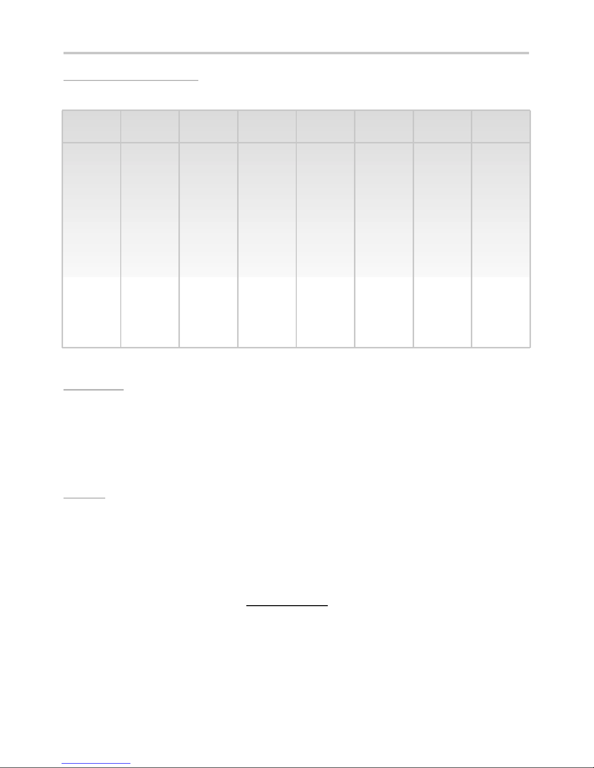
AFG SPECIFICATIONS
RANGE & RESOLUTION
Model no: mN N kN gf kgf ozf lbf
AFG2.5 2,500 x 0.5 2.5 x 0.0005 - 250 x 0.05 - 9 x 0.002 0.55 x 0.0001
AFG 5 5,000 x 1 5 x 0.001 - 500 x 0.1 0.5 x 0.0001 18 x 0.005 1.1 x 0.0002
AFG 10 10,000 x 2 10 x 0.002 - 1,000 x 0.2 1 x 0.0002 35 x 0.01 2.2 x 0.0005
AFG 25 25,000 x 5 25 x 0.005 - 2,500 x 0.5 2.5 x 0.0005 90 x 0.02 5.5 x 0.001
AFG 50 50,000 x 10 50 x 0.01 - 5,000 x 1 5 x 0.001 180 x 0.05 11 x 0.002
AFG 100 - 100 x 0.02 - 10,000 x 2 10 x 0.002 350 x 0.1 22 x 0.005
AFG 250 - 250 x 0.05 - 25,000 x 5 25 x 0.005 900 x 0.2 55 x 0.01
AFG 500 - 500 x 0.1 - 50,000 x 10 50 x 0.01 1,800 x 5 110 x 0.02
AFG 1000 - 1,000 x 0.2 1 x 0.0002 - 100 x 0.02 3,500 x 1 220 x 0.05
ACCURACY
± 0.1% of full-scale
Calibration temperature: 20°C ± 2°C
Operating temperature: 10°C - 35°C
Temperature shift at zero load: ± 0.01% of full-scale/°C
OUTPUT
RS232-C: 8 data bits, 1 Start bit, 1 Stop bit, no parity
Digimatic (Mitutoyo) format BCD output
Analogue: 0 to +4V full scale for tension (or clockwise)
0 to -4V full scale for compression ( or counter-clockwise)
(calibrated to order at factory)
PLC Signals: Relay description
The solid-state relay is mounted on a
PCB,which is hosed in a 15 pin D-type connector.
Connection to the relay output is via a 5metre length
screened cable. The end of the cable is left with bare
wires to allow appropriate termination to the peripheral
PLC device.
Page 29

page 27
AFG SPECIFICATIONS
PLC Signals (continued) Electrical
Supply voltage: The relay is powered from a 5 volt
regulator inside the AFG
Input control: The relay state is controlled via a TTL signal
from the AFG and is in a “closed position” when a logic
‘1’ input is applied.
Output characteristics
Peak relay ac voltage: 350 volts
Continuous relay load current or peak ac voltage: 120 mA
Maximum relay peak load current: 300 mA
Typical relay contact resistance at 100 mA: 17 ohms
Isolation voltage between AFG and relay output:1500 volts ac
ADAPTOR/CHARGER UNIT
The mains adaptor/charger supplied with the AFG is a constant-current type.
Primary: 230V – 50Hz (110V – 60Hz version also available)
Secondary: 100mA constant current at 9V
Charger pin: Centre = positive Outer = negative
Page 30
page 28
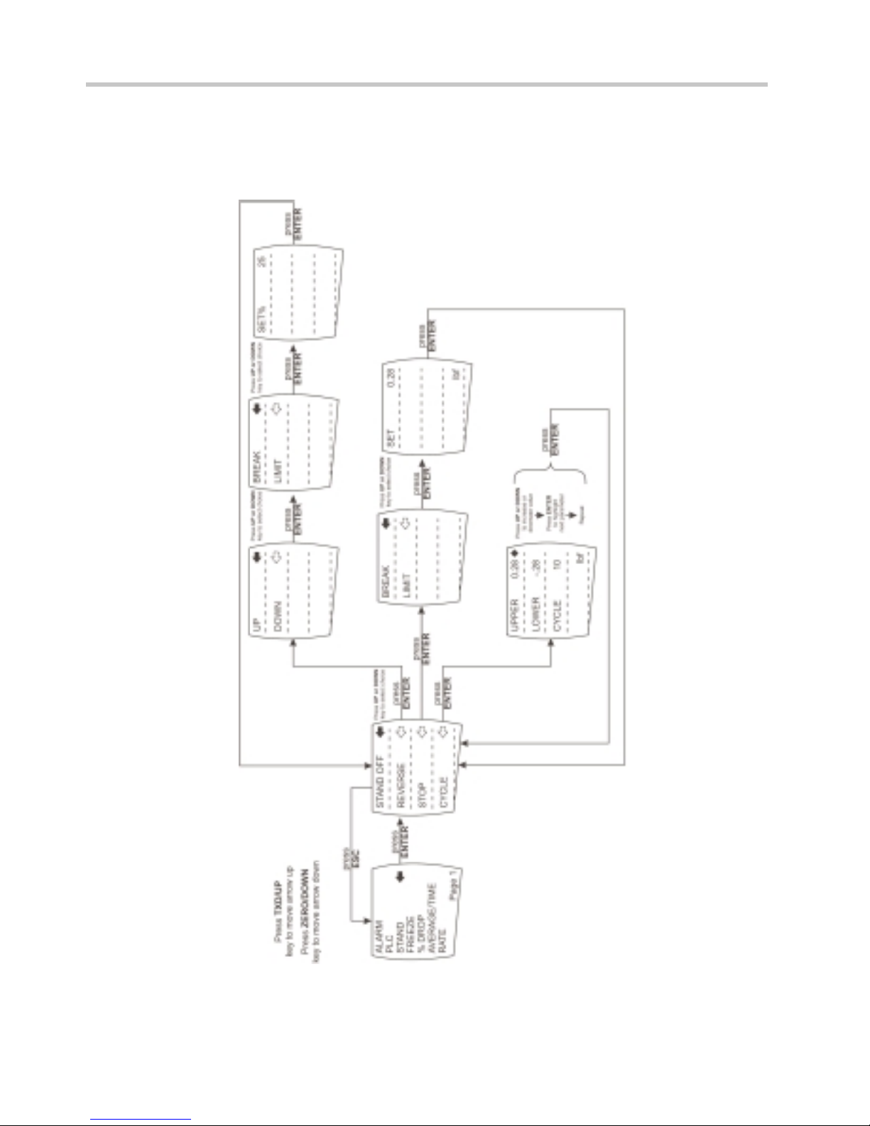
Advanced Menu Options Flow Chart Page 1
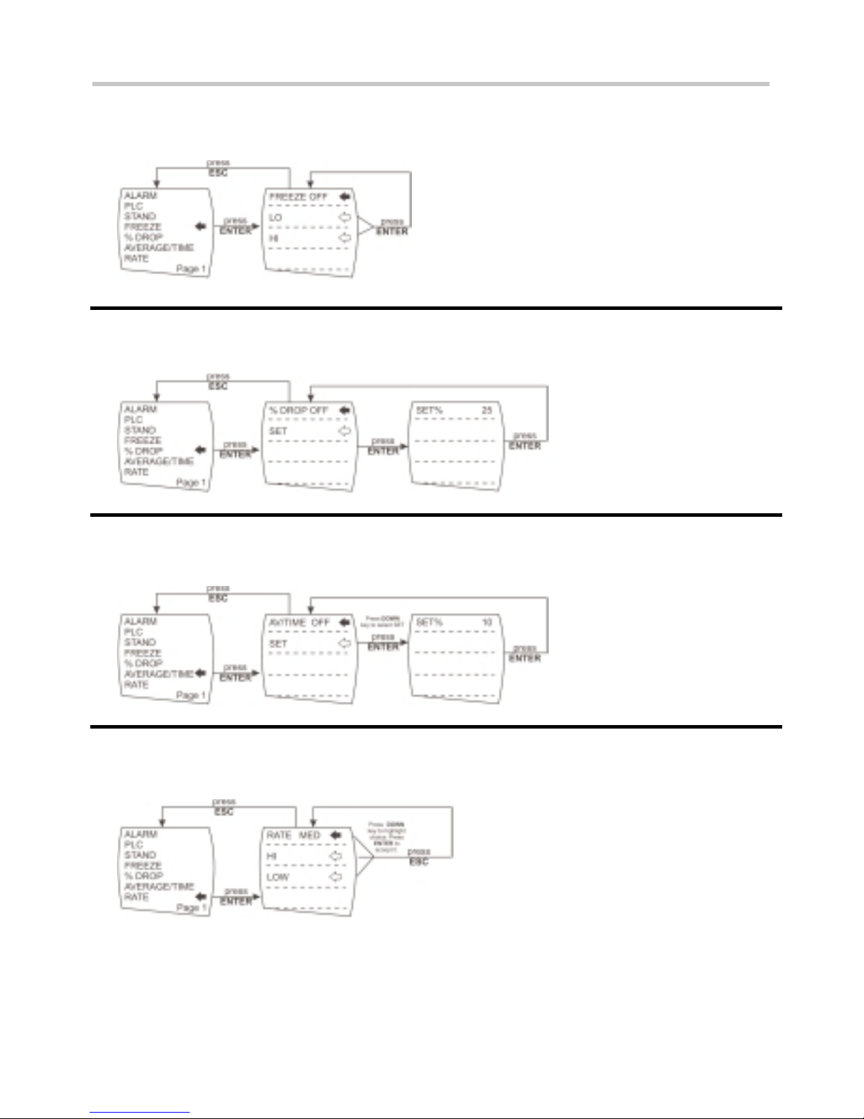
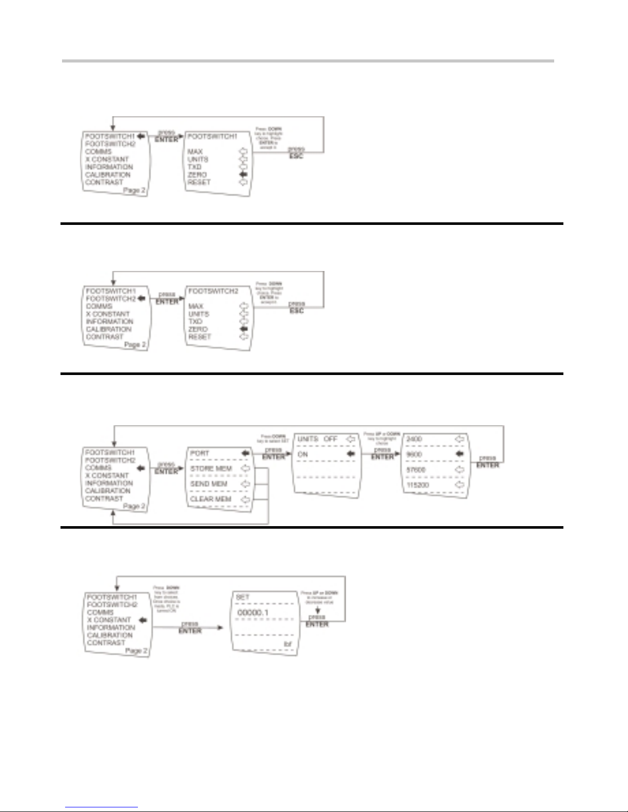
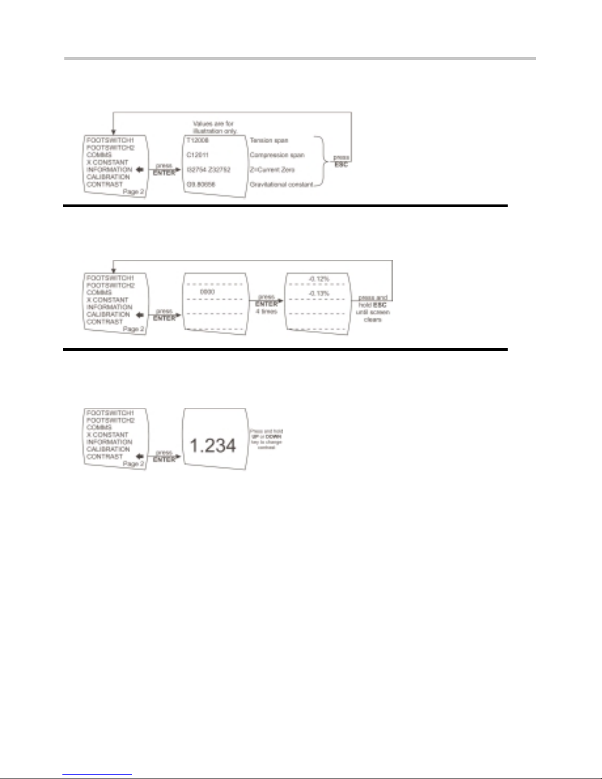
On the following pages are flowcharts to help you navigate the menus found in the AFG.
They appear in the order they appear on the two pages of the main menu on the Gauge.
Alarm
PLC
Page 31
page 29
Advanced Menu Options Flow Chart Page 1
Stand
Page 32
page 30
Advanced Menu Options Flow Chart Page 1
Freeze
% Drop
Average/Time
Rate
Page 33
page 31
Advanced Menu Options Flow Chart Page 2
Footswitch1
Footswitch2
Comms
Constant
x
Page 34
page 32
Advanced Menu Options Flow Chart Page 2
Information
Calibration
Contrast
Page 35
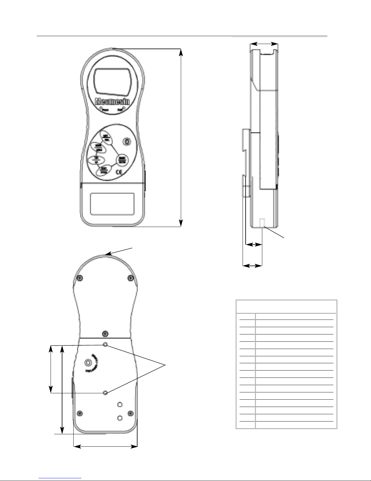
page 33
Dimensions (incl. Pin-out details)
Allocation for the pins on the
Male 15 way ‘D Type’
Communication Connector
AFG Mk 3 D Connector Pin Out:
1 Analogue Output
2 RS232 Transmit
3 RS232 Receive
4 Mitutoyo Clock Output
5 Mitutoyo Ready Output
6 + 5 Volts
7 FREEZE Reading Input
8 Stand Reverse UP
9 Footswitch 2 Input/SMART -ve out
10 Ground
11 Mitutoyo Request Input
12 Mitutoyo DATAOutput
13 Footswitch 1 input
14 PLC Output
15 Stand reverse DOWN
TAPPED HOLE:
THREAD M5 x 0.8 x
5.5mm DEEP
INTERNAL
LOADCELL STUD
THREAD
= M6 x 1.0
17mm
21mm
32mm
210mm
*
* Shown with Dovetail Mounting Bracket
(supplied with Mecmesin Test Stands)
57mm
105mm
76mm
BATTERY COVER
Front View Side View
Rear View
15 WAY D-TYPE
COMMUNICATION
CONNECTOR
Page 36
page 34
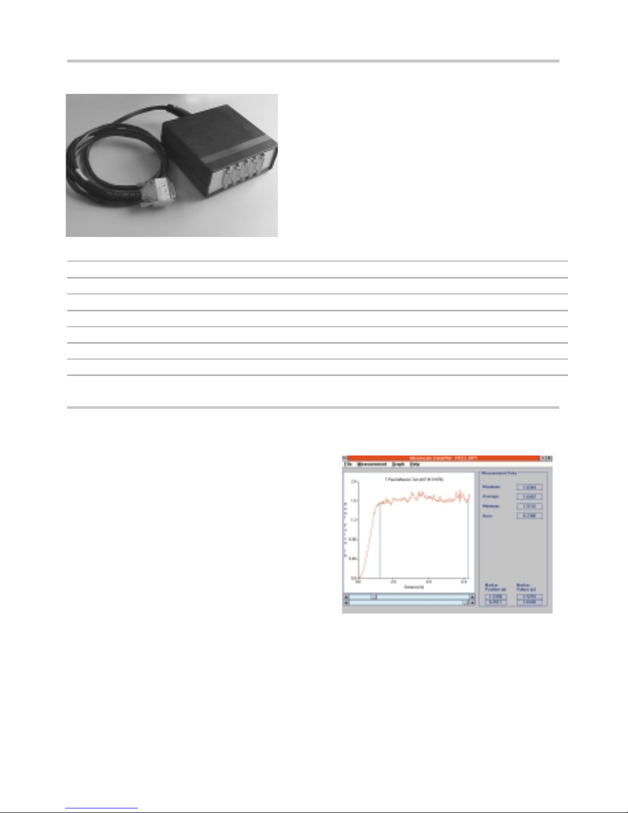
Optional Extras
CABLES PART NO.
Cable AFG to Mitutoyo Printer/DigiCon-X Interface 351 - 058
Cable AFG to RS 232 - 9 way 351 - 059
Cable AFG Analogue cable 351 - 060
Footswitch for AFG 351 - 061/V01/V02
Universal Expansion Module for AFG 432 - 185
Cable AFG to Versatest/UltraTest/M5KNE 351 - 062
Cable AFG to PLC 351 - 063
Universal Expansion Module shown for
connecting up to a maximum of 5 cables
simultaneously.
WINDOWS SOFTWARE FOR LOGGING, PLOTTING AND ANALYSING FORCE/TORQUE DATA
DataPlot enables a PC to communicate with
Mecmesin digital force gauges, torque gauges and
display units, by means of the bi-directional RS232
interface which is a standard feature of all
instruments. The PC functions as a virtual chart
recorder with the following features:
• Auto-ranging
• Zooming/re-scaling
• Overlaying of test traces
• Printout of tabular data
• ‘Smart-linked’ preference settings
• Start/stop triggers
• Data export to spreadsheets
DataPlot
Page 37

Page 38

Page 39

Page 40

 Loading...