

Page 1
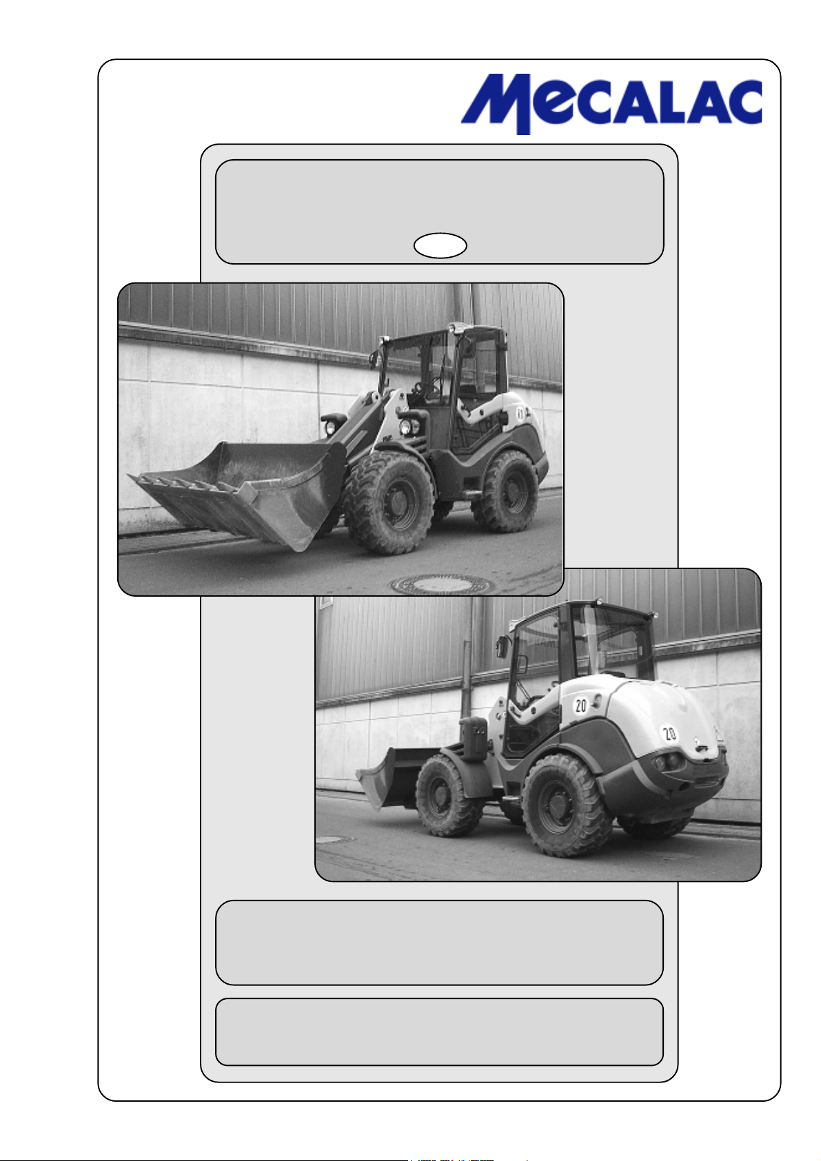
OPERATING INSTRUCTIONS
ARTICULATED LOADER
GB
AX 700 / AX 850 / AX 1000
MECALAC Baumaschinen GmbH Am Friedrichsbrunnen 2 D-24782 Büdelsdorf
Telefon (+49) (0)4331/351-325 Internet: www.mecalac.de
Telefax (+49)(0)4331/351-404 E-Mail: [email protected]
Page 2

You will find the
spare parts documentation
online at:
https://www.mecalac.de/abm_doc/
Log in as final customer and specify the FIN number (truck identification number) of
your MECALAC truck. When you already own an MECALAC truck, you can also view
the spare parts documentation here. To do so, please specify the FIN number of this
truck.
If required, you can print the documentation.
Page 3

Table of Contents
Introduction
Preface
MECALAC’s swivel shovel loaders, telescopic loaders, articulated loaders and front loaders are machines included
in the vast product range of MECALAC’s Baumaschinen covering a wide variety of working tasks.
Decades of experience in the construction of earth-moving machines, the wide range of attachments available as
well as modern production facilities, careful testing and highest quality demands guarantee the highest degree of
reliability of your MECALAC machine.
The documentation delivered by the manufacturer includes the following:
- Loader operating instructions
- Engine operating instructions
- Loader spare parts list
- Engine spare parts list
- EC conformity declaration
Operating instructions
The operating instructions contain all the information which the user requires for operation and maintenance.
In the “Maintenance” section, all maintenance work and operation tests are described which can be carried out
by trained personnel.
This section does not cover more extensive maintenance work that is reserved to personnel authorized and trained
by the manufacturer. In particular, this applies to facilities governed by Motor Vehicle Construction and Use
Regulations and the Regulations for the Prevention of Accidents.
Due to the construction modifications reserved by the manufacturer, there may be differences in the figures;
however, this has no influence on the technical contents.
How to use this manual
Explanations
- The designations “left” and “right” are to be seen from the driver’s seat in the driving direction.
- Special equipment
means: not fitted in series.
Information about illustrations
- (3-35)
means: chapter 3, fig. 35
- (3-35/1)
means: chapter 3, fig. 35, item 1
- (3-35/arrow)
means: chapter 3, fig. 35,
P0700/P0710/P0850/P0860/P1000/P1010 I
Page 4

Table of Contents
Abbreviations used
UVV = Unfallverhütungsvorschrift (Accident Prevention Regulations)
StVZO = Straßenverkehrzulassungsordnung (German Traffic Regulations)
Edition: 01.2012
Printed: 01.2012
P0700/P0710/P0850/P0860/P1000/P1010II
Page 5

Table of Contents
Table of Contents
1 Fundamental safety instructions
1.1 Warnings and symbols ................................................................................................................... 1-2
1.2 Proper use of the loader ................................................................................................................. 1-2
1.3 Organizational measures ................................................................................................................ 1-2
1.4 Selection of personnel and necessary qualifications; basic responsibilities ................................... 1-3
1.5 Safety information for certain operating phases ............................................................................. 1-4
1.5.1 Normal operation ............................................................................................................................ 1-4
1.5.2 Special work within the exploitation of the machine and elimination of defects
during process or work; disposal.................................................................................................... 1-7
1.6 Notes on special categories of danger ........................................................................................... 1-9
1.6.1 Electrical energy ............................................................................................................................ 1-9
1.6.2 Hydraulics .................................................................................................................................... 1-10
1.6.3 Noise ............................................................................................................................................ 1-10
1.6.4 Oil, grease and other chemical substances .................................................................................. 1-11
1.6.5 Gas, dust, steam, smoke .............................................................................................................. 1-11
1.7 Transport and towing; recommissioning ....................................................................................... 1-11
1.8 Safety information for the contractor or the contractor’s authorized personnel ........................... 1-12
1.8.1 Organizational measures .............................................................................................................. 1-12
1.8.2 Selection of personnel and necessary qualifications; basic responsibilities ................................. 1-12
2 Signs
3 Protection against theft
3.1 Identifying features on the loader ................................................................................................... 3-2
3.2 Parking the loader .......................................................................................................................... 3-2
3.3 Drive-away interlocks ..................................................................................................................... 3-3
3.3.1 Drive-away interlock transponder ................................................................................................... 3-3
3.3.2 Encodable drive-away interlock ...................................................................................................... 3-3
4 Description
4.1 Overview ......................................................................................................................................... 4-2
4.2 Loader ............................................................................................................................................ 4-3
4.3 Wheel change ................................................................................................................................ 4-6
4.4 Controls .......................................................................................................................................... 4-7
4.4.1 Multifunction panel .......................................................................................................................... 4-8
4.4.2 Emergency seat ............................................................................................................................. 4-8
4.4.3 Opening the window ....................................................................................................................... 4-9
4.5 Fuses/relays ................................................................................................................................... 4-9
4.6 Removing the driver’s cab ............................................................................................................ 4-10
5 Operation
5.1 Checks before start-up ................................................................................................................... 5-2
5.2 Start-up........................................................................................................................................... 5-2
5.2.1 Starting the diesel engine ............................................................................................................... 5-2
5.2.2 Winter operation ............................................................................................................................. 5-3
5.2.2.1 Fuel ................................................................................................................................................ 5-3
5.2.2.2 Engine oil change ........................................................................................................................... 5-3
5.2.2.3 Hydraulic system oil change ........................................................................................................... 5-3
5.2.2.4 Anti-freezing agent, windshield washer .......................................................................................... 5-4
5.2.3 Driving the loader on public roads .................................................................................................. 5-4
5.2.4 Working with the loader .................................................................................................................. 5-5
P0700/P0710/P0850/P0860/P1000/P1010 III
Page 6

Table of Contents
5.2.5 Heating and ventilation system ........................................................................................................ 5-6
5.2.5.1 Setting the air flow .......................................................................................................................... 5-6
5.2.5.2 Switching on the heater .................................................................................................................. 5-6
5.2.5.3 Switching on the air condition (opt.) ............................................................................................... 5-6
5.2.5.4 Setting the temperature .................................................................................................................. 5-6
5.2.5.5 De-icing/defogging the windshield .................................................................................................. 5-7
5.3 Decommissioning the loader .......................................................................................................... 5-7
5.3.1 Parking the loader .......................................................................................................................... 5-7
5.3.2 Switch off the diesel engine ............................................................................................................ 5-7
5.3.3 Switching off the heater and ventilation system .............................................................................. 5-7
5.3.4 Leaving the loader .......................................................................................................................... 5-7
5.4 Adjusting the driver’s seat .............................................................................................................. 5-8
5.4.1 Euro seat ........................................................................................................................................ 5-8
5.4.2 Grammer seat ................................................................................................................................. 5-8
6 Attachments
6.1 Mounting and dismounting attachments without hydraulic connections .......................................... 6-2
6.1.1 Standard/lightweight bucket ............................................................................................................ 6-2
6.1.2 Fork-lift attachment ......................................................................................................................... 6-3
6.2 Mounting and dismounting attachments with a hydraulic connection .............................................. 6-3
6.2.1 Multi-purpose bucket ...................................................................................................................... 6-3
6.3 Use of additional attachments ......................................................................................................... 6-5
7 Rescue, towing, lashing, lifting by crane
7.1 Rescue, towing, lashing .................................................................................................................. 7-2
7.1.1 Rescue/towing of the articulated loader if the engine or drive has failed ........................................ 7-2
7.1.1.1 Towing the articulated loader when the engine has failed ............................................................... 7-2
7.1.1.2 Towing the articulated loader when the traction drive has failed ..................................................... 7-5
7.2 Lifting by crane .............................................................................................................................. 7-6
8 Maintenance
8 Maintenance schedule .................................................................................................................... 8-1
8.1 Notes regarding maintenance ......................................................................................................... 8-3
8.2 Maintenance work .......................................................................................................................... 8-4
8.2.1 Oil level check, engine .................................................................................................................... 8-4
8.2.2 Oil change, engine ......................................................................................................................... 8-4
8.2.3 Maintaining/replacing the air filter .................................................................................................. 8-4
8.2.4 Replacing the safety cartridge (option) ........................................................................................... 8-5
8.2.5 Oil level check, front axle ................................................................................................................ 8-5
8.2.6 Oil change , front axle .................................................................................................................... 8-6
8.2.7 Oil level check , rear axle ................................................................................................................ 8-7
8.2.8 Oil change , rear axle ..................................................................................................................... 8-8
8.2.9 Oil level check , planetary gear ...................................................................................................... 8-9
8.2.10 Oil change, planetary gear ............................................................................................................. 8-9
8.2.11 Oil change, hydraulic system ......................................................................................................... 8-9
8.2.12 Changing the hydraulic oil filter cartridge ..................................................................................... 8-10
8.2.13 Grease points ............................................................................................................................... 8-11
8.2.13.1 Articulated pendulum joint/steering cylinder ................................................................................. 8-11
8.2.13.2 Bucket assembly .......................................................................................................................... 8-12
8.2.13.3 Driver’s cab doors ........................................................................................................................ 8-14
8.2.13.4 Engine hood ................................................................................................................................. 8-14
8.2.13.5 Multi-purpose bucket .................................................................................................................... 8-15
8.2.14 Oil lubrication points ..................................................................................................................... 8-15
8.2.15 Replacing the starter battery ......................................................................................................... 8-15
8.2.16 Maintaining/replacing the fresh air filter ....................................................................................... 8-16
8.2.17 Checking/adjusting the service/parking brake .............................................................................. 8-16
9 Faults, causes and remedies
P0700/P0710/P0850/P0860/P1000/P1010IV
Page 7

Table of Contents
10 Circuit diagrams
10.1 Electric circuit diagram ................................................................................................................ 10-3
10.1.1 Electric circuit diagram (air-conditioning system fan control) ...................................................... 10-7
10.2 Hydraulic circuit diagram ............................................................................................................. 10-9
11 Technical data (loader)
11.1 AX 700 ......................................................................................................................................... 11-2
11.1.1 Loader .......................................................................................................................................... 11-2
11.1.2 Engine .......................................................................................................................................... 11-2
11.1.3 Starter .......................................................................................................................................... 11-2
11.1.4 Alternator ...................................................................................................................................... 11-2
11.1.5 Hydrostatic drive ........................................................................................................................... 11-2
11.1.6 Axle loads ..................................................................................................................................... 11-2
11.1.7 Tyres ............................................................................................................................................ 11-3
11.1.8 Steering system ............................................................................................................................ 11-3
11.1.9 Brake system................................................................................................................................ 11-3
11.1.10 Electric system ............................................................................................................................. 11-3
11.1.11 Hydraulic system .......................................................................................................................... 11-3
11.1.12 Fuel supply system ....................................................................................................................... 11-3
11.1.13 Heating and ventilation system ...................................................................................................... 11-4
11.1.14 Return suction filter ...................................................................................................................... 11-4
11.1.15 Combination cooler ....................................................................................................................... 11-4
11.1.16 Noise emission ............................................................................................................................. 11-4
11.2 AX 850 ......................................................................................................................................... 11-5
11.2.1 Loader .......................................................................................................................................... 11-5
11.2.2 Engine .......................................................................................................................................... 11-5
11.2.3 Starter .......................................................................................................................................... 11-5
11.2.4 Alternator ...................................................................................................................................... 11-5
11.2.5 Hydrostatic drive ........................................................................................................................... 11-5
11.2.6 Axle loads ..................................................................................................................................... 11-5
11.2.7 Tyres ............................................................................................................................................ 11-6
11.2.8 Steering system ............................................................................................................................ 11-6
11.2.9 Brake system................................................................................................................................ 11-6
11.2.10 Electric system ............................................................................................................................. 11-6
11.2.11 Hydraulic system .......................................................................................................................... 11-6
11.2.12 Fuel supply system ....................................................................................................................... 11-6
11.2.13 Heating and ventilation system ...................................................................................................... 11-7
11.2.14 Return suction filter ...................................................................................................................... 11-7
11.2.15 Combination cooler ....................................................................................................................... 11-7
11.2.16 Noise emission ............................................................................................................................. 11-7
11.3 AX 1000 ....................................................................................................................................... 11-8
11.3.1 Loader .......................................................................................................................................... 11-8
11.3.2 Engine .......................................................................................................................................... 11-8
11.3.3 Starter .......................................................................................................................................... 11-8
11.3.4 Alternator ...................................................................................................................................... 11-8
11.3.5 Hydrostatic drive ........................................................................................................................... 11-8
11.3.6 Axle loads ..................................................................................................................................... 11-8
11.3.7 Tyres ............................................................................................................................................ 11-9
11.3.8 Steering system ............................................................................................................................ 11-9
11.3.9 Brake system................................................................................................................................ 11-9
11.3.10 Electric system ............................................................................................................................. 11-9
11.3.11 Hydraulic system .......................................................................................................................... 11-9
11.3.12 Fuel supply system ....................................................................................................................... 11-9
11.3.13 Heating and ventilation system ...................................................................................................... 11-9
11.3.14 Return suction filter .................................................................................................................... 11-10
11.3.15 Combination cooler ..................................................................................................................... 11-10
11.3.16 Noise emission ........................................................................................................................... 11-10
P0700/P0710/P0850/P0860/P1000/P1010 V
Page 8

Table of Contents
12 Technical data (attachments)
12.1 AX 700 attachments ..................................................................................................................... 12-2
12.1.1 Buckets ........................................................................................................................................ 12-2
12.1.2 Fork-lift attachment ....................................................................................................................... 12-4
12.1.3 Lifting hook ................................................................................................................................... 12-4
12.2 AX 850 attachments ..................................................................................................................... 12-6
12.2.1 Buckets ........................................................................................................................................ 12-6
12.2.2 Fork-lift attachment ....................................................................................................................... 12-8
12.2.3 Lifting hook ................................................................................................................................... 12-8
12.3 AX 1000 attachments ................................................................................................................. 12-10
12.3.1 Buckets ...................................................................................................................................... 12-10
12.3.2 Fork-lift attachment ..................................................................................................................... 12-12
12.3.3 Lifting hook ................................................................................................................................. 12-12
13 Additional options
13.1 Additional options ......................................................................................................................... 13-2
P0700/P0710/P0850/P0860/P1000/P1010VI
Page 9

Safety regulations
Page 10
1 Safety regulations
1 Fundamental safety instructions
1.1 Warnings and symbols
In this operation manual, the following designations or
symbols are used for important information.
NOTE
Extra information about the economical use of
the loader.
CAUTION
Special information for regulations and prohibitions for avoiding damage.
DANGER
Information or regulations and prohibitions for
prevention of damage to persons or extensive
damage to goods.
1.2 Proper use of the loader
1.2.1 This machine was designed according to the
state of the art and recognised safety rules. Nevertheless
the use of the machine may cause danger for the user or
third parties or impairments to the machine or other real
values.
1.2.2 The machine and manufacturer-approved attachments may only be used in a technical non-objectionable
condition, taking all safety regulations especially with
regard to the operating manuals (machine and engine). In
particular defects which could have a detrimental effect on
the safety of the machine should be eliminated immediately.
1.2.3 The machine is designed exclusively for the
purposes described in this operating manual. Any other
use beyond these purposes is regarded as being improper
use. The manufacturer is not liable for any damage caused
in this connection. The risk is solely that of the user.
The authorized use of the machine also requires the
operating manual (machine and engine) is heeded and the
inspection and maintenance conditions are complied with.
1.3 Organizational measures
1.3.1 The operating manual (machine and engine)
must be available at all times and at the site where the
machine is in operating condition.
P070/P071/P085/P086/P100/P1011-2
Page 11

1.3.2 In addition to the operating manual (machine and
engine) the general applicable and other binding regulations for the prevention of accidents (especially the safety
regulations of the German Trade Association - VBG 40) as
well as the regulations for environment protection must be
observed and the personnel must be accordingly.
Also heed all regulations governing public traffic.
1.3.3 The personnel in charge of working with the
machine must read the operating manual (machine and
engine) before start of work, especially the chapter concerning safety precautions.
This also applies to personnel working occasionally with
the machine, e.g. during maintenance work.
1.3.4 The driver must wear a seat belt during operation.
1.3.5 Personnel working with the machine must not
wear long flowing hair, loose clothing or jewellery, including
rings. Danger of injuries, e.g. by getting caught or being
pulled in.
Safety regulations 1
1.3.6 All safety and danger plates on the machine must
be observed!
1.3.7 All safety and danger plates must be attached to
the machine and must be kept in legible condition.
1.3.8 In case of modifications to the machine, espe-
cially in case of damages or changes in the operating
behavior of the machine which could influence the safety of
the machine, stop the machine immediately and inform the
competent person in charge about the incident.
1.3.9 Do not make any modifications or conversions to
the machine which could affect safety without the manufacturer’s consent. This also applies to the installation and
adjustment of safety devices, valves and welding work to
supporting parts.
1.3.10 Check the hydraulic system, especially hydrau-
lic pipes, at regular intervals for defects and immediately
eliminate any defects found.
1.3.11 The prescribed inspection periods set down in
the operating manual (machine and engine) and the
maintenance plan must be observed.
1.4 Selection of personnel and necessary
qualifications; basic responsibilities
1.4.1 The machine may be driven and maintained only
by personnel selected by the employer for this purpose.
P070/P071/P085/P086/P100/P101 1-3
Page 12

1 Safety regulations
These persons must:
- have attained the age of 18 years,
- be physically and intellectually suitable,
- have been instructed in the operation or maintenance of
the machine and must have demonstrated their ability to
their employer,
- must be expected to carry out the work conveyed to them
in diligent manner.
1.4.2 Electrical work on the machine may be carried
out only by a qualified electrician or persons supervised by
a qualified electrician according to the electrical regulations.
1.4.3 Only qualified specialists may carry out work on
the chassis, the brake and steering system.
1.4.4 Only personnel with special experience and the
necessary know-how are permitted to carry out work on the
hydraulic system.
1.5 Safety information for certain opera-
ting phases
1.5.1 Normal operation
1.5.1.1 A passenger may only be transported in a dedi-
cated passenger seat!
1.5.1.2 Start and drive the machine from the driver’s seat
only!
1.5.1.3 Observe the control lamps according to the opera-
tion manual (machine and engine) during starting and
switching-off operation!
1.5.1.4 Before commencing work/driving check brakes,
steering, signal lights and lights for their functioning!
1.5.1.5 Before moving the machine always check that
the attachments are safely stowed so that no accident
may occur!
1.5.1.6 Before commencing work, make yourself familiar
with the working environment. This means observing
obstacles on the working site, quality and resistance of the
soil ground, undertaking the necessary protection
precautions between the building site and the public traffic.
1.5.1.7 Before starting the machine make sure that no
person is endangered by the moving machine!
1.5.1.8 Take measures so that the machine can be
operated only in a safe and functional manner. The
machine may only be operated when all safety devices,
e.g. detachable safety devices and sound absorption,
exist and function.
P070/P071/P085/P086/P100/P1011-4
Page 13

1.5.1.9 Avoid any action which appears to be dangerous!
1.5.1.10 Persons must not be carried in the working
equipment, e.g. in the attachments!
1.5.1.11 The operator may carry out work with the machine
only if no persons are in the danger zone.
The danger zone is the area near the machine where
persons may be injured
- by work-induced movements of the machine,
- by work attachments and devices,
- by loads swinging out,
- by dropping loads,
- by attachments falling down from the machine.
1.5.1.12 In case of danger to persons the operator must
give appropriate warning signs. It may be necessary to
stop work.
1.5.1.13 In case of functional defects, stop the machine
immediately and secure it. Eliminate defects immediately!
Safety regulations 1
1.5.1.14 Check the machine at least once every shift for
external visible damage and defects. Report any defects
(including changes in the operational behavior) immediately to the person in charge. If necessary stop the
machine immediately and safeguard it.
1.5.1.15 The driver may slew the attachments in overhead
driving, operating and working areas only if these areas are
suitably safeguarded by protective roofing. These protection roofs must offer appropriate safety against loads and
falling goods. If you are in doubt, assume no protection
roofs are present.
1.5.1.16 When driving, the attachment is to be kept as
close to the ground as possible.
1.5.1.17 Please observe the applicable traffic regulations
when driving on public roads, paths or open spaces. The
machine must be brought into road-worthy condition beforehand.
1.5.1.18 Make sure to always switch on lights in poor
visibility and during darkness.
1.5.1.19 If the lights of the machine are not adequate for
the safe execution of certain work, additional lighting must
be provided on the working site, especially at dumping
points.
1.5.1.20 Should the driver’s sight of his driving and working
area be restricted due to work-induced influences, he must
be given guidance or he must safeguard the working area
by a firm barrier.
P070/P071/P085/P086/P100/P101 1-5
Page 14

1 Safety regulations
1.5.1.21 Only reliable persons may act as guides. They
must be informed of their duties prior to commencing work.
1.5.1.22 The driver and guide must agree on signals for
communication. These signals may only be given by the
driver and guide.
1.5.1.23 The guide must be easily recognizable – e.g. by
wearing warning clothing – and must always be in the
driver’s field of vision.
1.5.1.24 When passing subways, bridges, tunnels, elec-
trical over-head lines make sure that there is adequate
clearance!
1.5.1.25 Maintain adequate clearance when working at
the edge of quarries, pits, rubbish dumps and embankments to eliminate any danger of the machine plunging
down. The contractor or his deputy must stipulate the
distance from the edge taking the soil bearing capacity into
consideration.
1.5.1.26 The machine may only be used at stationary
dumping areas when firmly integrated installations are
provided to prevent the machine from running or sliding
down.
1.5.1.27 Avoid such work which could have a detrimental
effect on the stability of the machine.
The following may affect the stability:
- overloading,
- ground that is too soft,
- abrupt acceleration or deceleration of driving or working
movement,
- reversing out of a high driving speed,
- working on slopes,
- driving too quickly round sharp bends,
- driving the machine on rough terrain.
1.5.1.28 Do not traverse across slopes. Always carry
working equipment and loads near the ground, especially
when driving down slopes. Sudden cornering is forbidden!
1.5.1.29 On steep inclines and gradients, the load is to be
carried on the uphill side.
1.5.1.30 Always adapt the speed of the machine to the
environmental conditions when driving down slopes!
Never change into low gear when driving on slopes, but
rather before the slope!
1.5.1.31 Reversing over a longer period must be avoided!
1.5.1.32 When leaving the machine always safeguard the
machine to prevent it from unintentionally rolling away or
prevent non-authorized persons from using it!
1.5.1.33 The driver must not leave the machine if the
attachments are not lowered or safeguarded.
P070/P071/P085/P086/P100/P1011-6
Page 15
1.5.1.34 During breaks and after work hours, the driver
must park the machine on solid and, if possible, level
ground and safeguard it against unintentionally rolling
away.
1.5.2 Special work within the exploitation
of the machine and elimination of defects
during process or work; disposal
1.5.2.1 The dates for adjustment work, maintenance
work and inspections laid down in the operating manual
(machine and engine) must be strictly observed. This also
applies to details regarding the replacement of parts/part
equipment. This work may only be executed by skilled
personnel.
1.5.2.2 For all work concerning the operation, conversion
or adjustment of the machine and its safety devices as well
as inspection, maintenance and repair work please observe the switch-on and switch-off procedures in accordance with the operating manual (machine and engine) as
well as the related instructions for maintenance work.
Safety regulations 1
Figure 1-1
1.5.2.3 The engine must be switched off before maintenance or repair work is carried out.
1.5.2.4 The stability of the machine or the attachments
must be guaranteed at all times during maintenance and
repair work.
1.5.2.5 Maintenance and repair work may only be carried
out when the attachment is set down on the ground or
supported or when equivalent measures against unintentional movement were taken.
During maintenance and repair work under the bucket arm:
- the bucket arm must be mechanically supported:
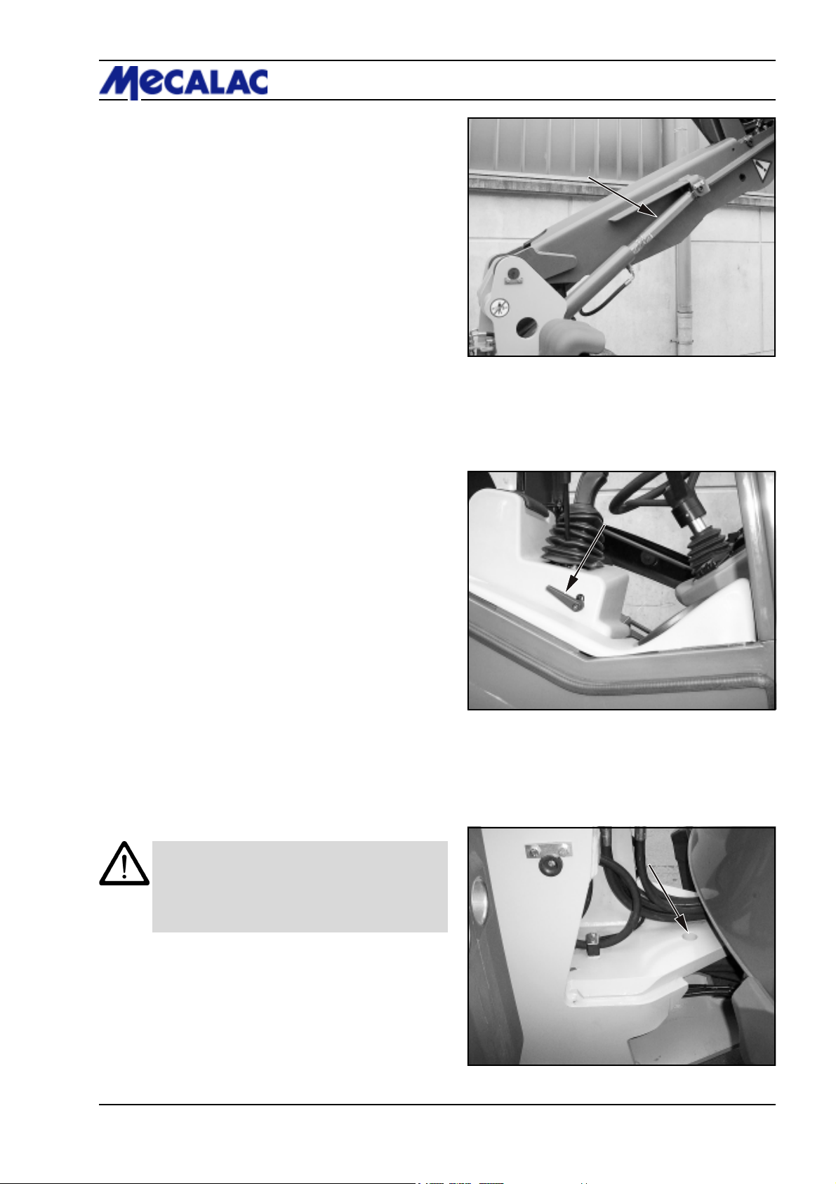
e.g. take the bucket arm support (option) off the left
loader front after having unscrewed the fastening screw/
nut and insert it in the lifting cylinder (1-1/arrow),
- the pilot valves for working and auxiliary hydraulics (1-2/
arrow) must be closed (rear position).
1.5.2.6 Secure the articulated link against buckling when
performing maintenance and repair work on it.
Take the bolt out of the rear tow coupling and insert it in the
articulation joint (articulation safeguard) (1-3/arrow).
CAUTION
- The steering must be in a straight ahead position
when you insert the bolt.
- Do not operate the steering while the articulation
safeguard is in place.
Figure 1-2
1.5.2.7 If necessary, secure the maintenance area on a
large scale.
1.5.2.8 The machine must be protected from unintentionally starting after it was switched off for maintenance
and repair work:
- remove the ignition key and
- attach at warning sign at the disconnected battery or at
the battery main switch.
This applies especially to works to the electrical equipment.
Figure 1-3
P070/P071/P085/P086/P100/P101 1-7
Page 16

1 Safety regulations
1.5.2.9 Individual pieces and large assemblies must be
carefully secured to hoisting equipment when being replaced to avoid any damage. Only suitable and technically
sound hoisting equipment may be used as well as crane
equipment with adequate payload. Do not stand or work
underneath suspended loads!
1.5.2.10 Only experienced personnel should be entrusted
with the securing of loads!
Loads must be secured so that they cannot slip or fall
down.
1.5.2.11 Attached loads may only be moved with the
machine when the road is graded.
1.5.2.12 When working with hoisting equipment / elevators the slingers may only work with the approval of the
driver and from the side of the boom. The driver may only
give his consent if the machine is standing still and the
working attachment is not being moved.
1.5.2.13 Persons assisting with the guidance of loads and
slingers may only stay in visual or communication reach of
the driver.
1.5.2.14 The operator must move the load as close to the
ground as possible and avoid swivelling the load.
1.5.2.15 The operator may not move the load over the
heads of persons.
1.5.2.16 In the case of erection work that must be carried
out above normal human height, suitable safety ascent
devices and working platforms must be used. Do not use
engine parts, in particular attachments such as buckets,
as climbing and descending facilities. Use safety harnesses
when working at very great heights.
All handles, steps, railings, platforms, scaffolds, and
ladders must be kept free from dirt and ice.
1.5.2.17 Clean the machine, especially connections and
screw connections, before commencement of maintenance work and make sure that the machine is free from oil,
fuel oil or dirt. Do not use aggressive detergents. Use
lintless cleaning rags!
1.5.2.18 Before cleaning the machine with water or steam
jet (high pressure cleaning unit) or with detergent, protect
all areas where water/steam/detergent may penetrate and
affect the functions or safety of the machine by a suitable
cover or by applying tape. In particular, such parts as
engine components, e.g. alternator, generator governor,
starter, air filter, cables and hoses are very delicate.
1.5.2.19 After cleaning completely remove all protection
covering and tape.
1.5.2.20 After cleaning check all pipelines for fuel, engine
oil and hydraulic oil for leakages, loose connections,
abrased parts and damages. Eliminate defects immediately!
P070/P071/P085/P086/P100/P1011-8
Page 17
1.5.2.21 Always fasten screw connections after comple-
tion of maintenance and repair work.
1.5.2.22 Should it be necessary to dismantle safety devices
during mounting, maintenance or repair work, these safety
devices must be re-installed and checked carefully after
completed maintenance and repair work.
1.5.2.23 Make sure that fuel, accessory material and
interchanged parts are safely disposed of with no danger
to the environment.
1.5.2.24 The machine should be checked by a specialist
before commissioning and after essential modifications
before it returns to service.
1.5.2.25 The machine must be checked by a specialist
once a year. Furthermore, a specialist must check the
machine whenever necessary according to operating conditions.
1.5.2.26 The test results must be recorded and kept in the
archives at least until the following inspection date.
Safety regulations 1
1.6 Notes on special categories of danger
1.6.1 Electrical energy
1.6.1.1 Only use original fuses with stipulated ratings.
Immediately switch off the machine if the electrical supply
fails.
1.6.1.2 When working near overhead lines and overhead
wires, a safety clearance must be kept between the
machine and its working equipment in order to prevent
sparking over. The safety clearance depends on the
nominal voltage of the overhead/wire line. This also applies
to the distance between the lines and to the attachments
and slung loads.
The following safety clearance must be observed to meet
the above mentioned requirement:
Nominal voltage Safety clearance
(kilovolts) (metres)
up to 1 kV 1.0 m
from 1 kV to 110 kV 3.0 m
from 110 kV to 220 kV 4.0 m
over 220 kV to 380 kV 5.0 m
unknown voltage 5.0 m
When approaching overhead lines, all working movements
of the machine must be taken into consideration, e.g. the
position of jibs, the swinging of ropes and the dimensions
of attached loads.
In addition, attention must be paid to any roughness of soil
which could cause an inclined position of the machine,
thus getting it closer to the overhead line.
The fact that overhead lines may swing out during windy
weather and may reduce the distance must also be taken
into consideration.
P070/P071/P085/P086/P100/P101 1-9
Page 18

1 Safety regulations
1.6.1.3 In the case of sparking over, the driver must bring
the machine out of the danger area by lifting or lowering the
attachments or by swivelling away or driving the machine
out of the danger area. If this is not possible then the
following rules must be observed:
- Do not leave the driver’s cabin!
- Warn persons standing near the machine not to approach
or touch the machine!
- Give immediate instructions to have the power cut off!
- Leave the machine only when it is sure that the electricity
in the damaged / contacted power line is switched off so
that the line is dead!
1.6.1.4 Work on the electrical system or on the operating
system may only be carried out by a skilled electrician or
by personnel instructed or supervised by such a trained
electrician according to electrotechnical regulations.
1.6.1.5 The electrical installation of a machine must be
reviewed/inspected at regular intervals. Any defects, e.g.
loose connections or scorched cabling, must be eliminated
immediately.
1.6.1.6 The cable must be disconnected from the nega-
tive pole of the battery before inspection, maintenance or
repair of machine parts and components.
1.6.1.7 Electric welding operations may only be per-
formed if the battery main switch (8-35/3) has been pulled
out.
1.6.2 Hydraulics
1.6.2.1 Only experts with special expertise and expe-
rience may carry out work on the hydraulic system!
1.6.2.2 All pipelines, hoses and screw connections must
be checked regularly for leakages and visible damage!
Immediately repair such defects! Spurting hydraulic oil
may cause injuries and fire.
1.6.2.3 Those hydraulic system segments which are to
be opened must be depressurised before commencement
of the repair work according to the assembly group description!
1.6.2.4 The hydraulic pipelines must be correctly laid and
connected! Do not mix up the connections. Spare parts
must meet the technical requirements of the manufacturer.
Original spare parts ensure the fulfilment of these requirements.
1.6.2.5 The factory settings of hydraulic components
(e.g. the maximum permissible speed of the axial piston
engine) must not be altered. Any adjustment will render the
warranty invalid.
1.6.3 Noise
Sound protection equipment must be in protective position
during operation of the machine.
P070/P071/P085/P086/P100/P1011-10
Page 19
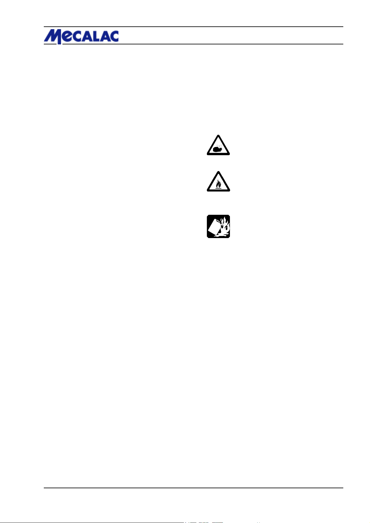
1.6.4 Oil, grease and other chemical substances
1.6.4.1 The relevant safety regulations must be observed
when handling oil, grease or other chemical substances.
1.6.4.2 Caution when working with hot fuel and other
accessory materials (danger of burning and scalding).
1.6.4.3 Caution when working with brake fluid and battery
acid.
TOXIC AND CAUSTIC!
1.6.4.4 Be careful when working with fuel.
FIRE HAZARD!
- Before refuelling, switch off the engine and remove the
ignition key.
- Do not refuel in an enclosed area.
- Never refuel near open fire or sparks.
- Do not smoke during refuelling.
- Immediately wipe up spilled fuel.
- Keep the machine free of fuel, oil and grease.
Safety regulations 1
1.6.5 Gas, dust, steam, smoke
1.6.5.1 The machine may be operated in closed rooms
only if sufficient ventilation is ensured! Ensure sufficient
ventilation prior to starting the machine!
The regulations for the respective working site must be
strictly observed.
1.6.5.2 Carry out welding, burning and grinding work on
the machine only when this is explicitly approved. Otherwise, there is the danger of fire and explosion!
1.6.5.3 Before carrying out welding, burning and grinding
work clean the machine and its vicinity from combustibles
and make sure that the room is adequately ventilated.
Explosion hazard!
1.7 Transport and towing;
recommissioning
1.7.1 The machine may only be towed if the brakes and
steering function.
1.7.2 Towing may be carried out only by means of an
adequately dimensioned towing bar in connection with
towing devices.
1.7.3 Start towing at a low speed. Persons must not be
near the towing bar.
P070/P071/P085/P086/P100/P101 1-11
Page 20
1 Safety regulations
1.7.4 When the machine is loaded and transported, the
necessary auxiliary equipment must be fitted to prevent
any unintended movement. The tyres must be kept clean
of mud, snow and ice so that the machine can drive on
ramps without danger of sliding.
1.7.5 Strictly observe the operating manual during
recommissioning.
1.8 Safety information for the contractor
or the contractor’s authorized personnel
1.8.1 Organizational measures
1.8.1.1 We emphasise that attachments that are not
supplied by us are also not tested and approved by us. Use
of such products can under certain conditions adversely
affect the present constructional qualities of your loader
and thus limit the active and passive driving safety. The
manufacturer cannot be held responsible for damage that
occurs through the use of such products.
Figure 1-4
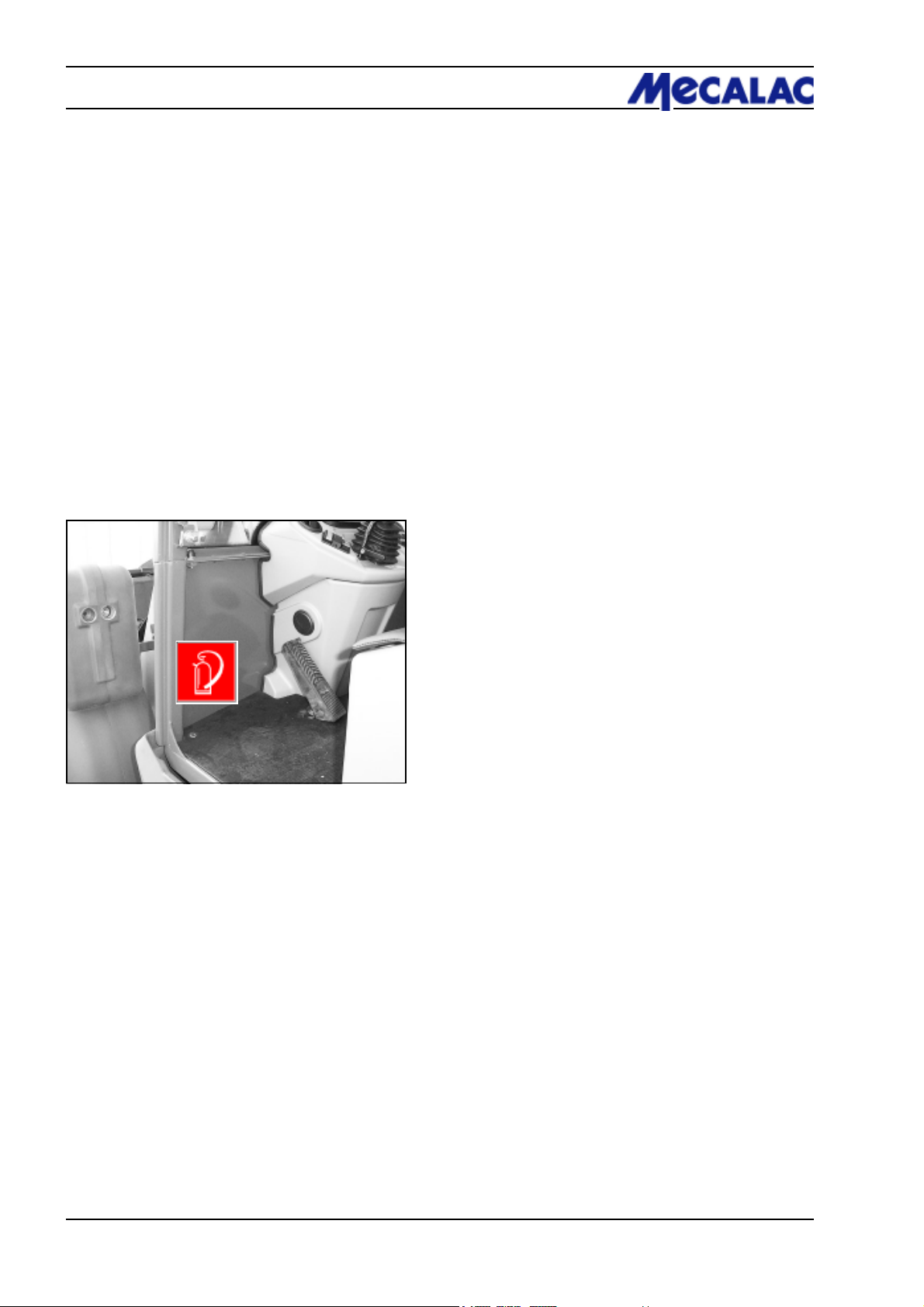
1.8.1.2 Inform yourself of the location/use of fire extinguishers (1-4/arrow) and first-aid kit!
1.8.1.3 When travelling on public roads, a first-aid kit, a
warning triangle and a warning lamp must be available on
the vehicle.
1.8.2 Selection of personnel and necessary qualifications; basic responsibilities
1.8.2.1 Only reliable persons are allowed to work on/with
the machine. The minimum legal age must be observed.
1.8.2.2 Employ trained or instructed personnel only.
Clearly define the competencies of the personnel regarding
operation, installation, maintenance and repair work.
Ensure that only authorised personnel may work on/with
the machine!
1.8.2.3 Authorize the drive to refuse instructions given by
third parties when these instructions are detrimental to the
safety of the driver and the machine.
1.8.2.4 Personnel who are to be trained, instructed or
working on/ with the machine in the scope of professional
training must not work on/ with the machine, unless they
are supervised by an experienced person.
P070/P071/P085/P086/P100/P1011-12
Page 21

Signs
Page 22
2 Signs
Baujahr
kW
Fahrzeug Identifizierungs Nr. (FIN)
Motorleistung:
Typ/
Ausf.
zul. Achslast hinten
zul. Achslast vorn
zul. Gesamtgewicht
Betriebserlaubnis Nr.
2-
1-
Baumaschinen GmbH
D-24782 Büdelsdorf
kg
kg
kg
1
16
13
12
2
3
CAUTION!
Steering only possible
when engine is running!
4
CAUTION!
The hydraulic quick-change device
must only be locked if an attachment
has been mounted.
The lift cylinders’ pipe break protection is disabled when the lifting
suspension is switched on.
Do not switch on the lifting suspension while the fork-lift or lifting hook
attachment is fitted.
5
CAUTION!
6
7
8
CAUTION!
Use mineral oil DIN 51524HVLP 46 ISO VG 46 VI
> 180
9
Diesel
fuel only
10
11
1415
20
20
26
25
10
13
12.5 -18 3,0 2,5-3,0 bar
405/70 R 18 3,0 2,5-3,0 bar
14.5 - 20 3,0 2,5-3,0 bar
405/70 R 20 3,0 2,5-3,0 bar
181711
19 20
21
27
12
22
23
24
1
13
12
11
16
13
12
20
P078/P079/P088/P089/P108/P1092-2
Page 23

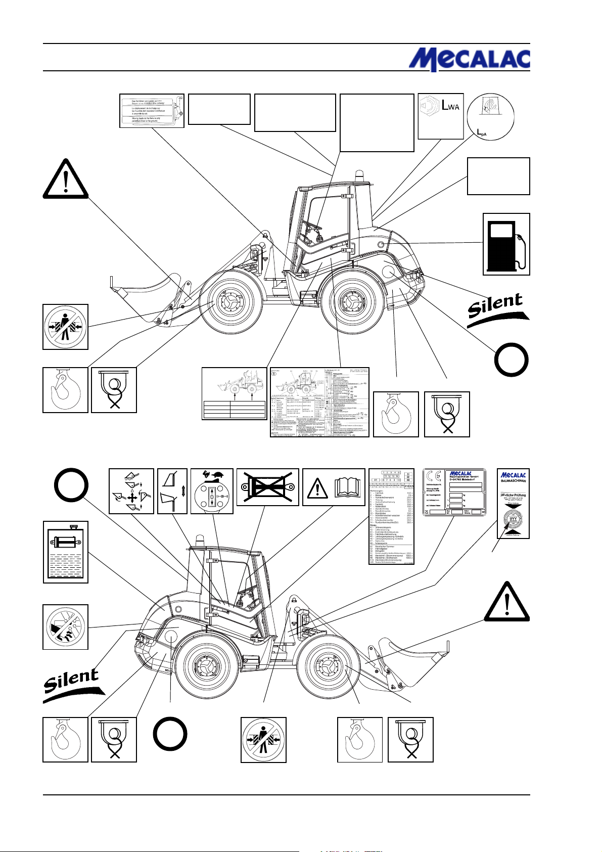
1 Symbol: Stay out of the danger zone
2 Sign: Moving loads on the forks is only permitted close to the ground!
3 Sign: CAUTION! - Steering only possible when engine is running!
4 Sign: CAUTION!
The hydraulic quick-change device must only be locked if an attachment has been
mounted.
5 Sign: » Only for loaders with pipe break protection «
CAUTION!
The lift cylinders’ pipe break protection is disabled when the lifting suspension
is switched on.
Do not switch on the lifting suspension while the fork-lift or lifting hook attach-
ment is fitted.
6 Sign: Noise pressure level (chapt. 11.1.16, 11.2.16, 11.3.16)
7 Sign: Sound power level (chapt. 11.1.16, 11.2.16, 11.3.16)
8 Sign: Use mineral oil DIN 51524-HVLP 46 ISO VG 46 VI > 180
9 Symbol: Fuel tank
10 Sign: Lettering “Low-noise construction machine”
11 Sign: Maximum speed
12 Symbol: Lashing eye
13 Symbol: Lifting hook
14 Sign: Maintenance schedule
15 Sign: Tyre pressure
16 Symbol: Stay out of the unprotected articulation area
17 Symbol: Pilot valve for working hydraulics (4-8/4)
- Hand lever forward - Lower bucket arm
- Hand lever forward beyond its pressure point - Floating position
- Hand lever to the rear - Lift bucket arm
- Hand lever to the left - Tilt up quick-change device/attachment
- Hand lever to the right - Tilt down quick-change device/attachment
18 Symbol: Pilot valve for auxiliary hydraulics (4-8/5)
19 Symbol: Standard joystick
- Drive switch (4-10/11)
- Drive direction - forward
- 0
- reverse
- Pushbutton for differential lock (4-10/10)
- Hydraulic drive stages (4-10/9)
- Hare symbol - fast
- Snail symbol - slow
20 Symbol: Working and auxiliary hydraulics locked
21 Symbol: Read and observe the operating instructions before commissioning.
Make sure that all other users have read the safety instructions!
22 Machine type label (includes the identification number of the vehicle)
23 Sign: Annual inspection as per UVV
24 Sign: UVV badge
25 Symbol: Open only when the engine is not running
26 Symbol: Hydraulic oil tank
27 Sign: Fuses/relays
Signs 2
P078/P079/P088/P089/P108/P109 2-3
Page 24

Page 25

Protection against theft
Page 26
3 Protection against theft
3 Protection against theft
Instances where construction machines were stolen have
considerably increased in recent years.
To make it possible for the police, customs and other
authorities to find and identify machines much faster,
MECALAC construction machines are fitted with the
following identifying features:
Figure 3-1
Figure 3-2
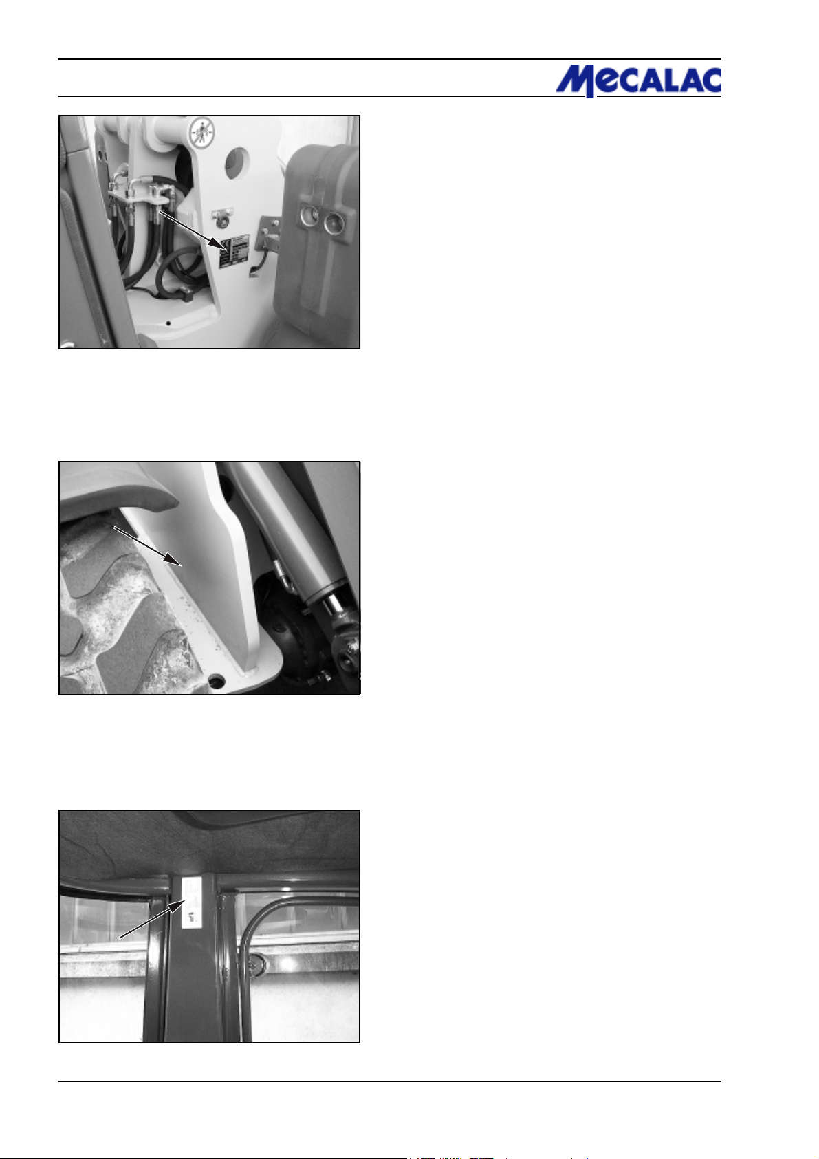
3.1 Identifying features on the loader
(1) Loader type plate (3-1/arrow). Among other details,
the loader type plate also gives the 17-digit FIN number
(truck identification number) ( starting with W09.
(2) The FIN number is also stamped into the front part
(3-2/arrow) of the loader.
(3) ROPS plate (3-3/arrow).
This plate gives the name of the manufacturer as well as
details on the ROPS type, the loader type and the permissible overall weight.
3.2 Parking the loader
(1) Turn the steering wheel fully to the left or the right.
(2) Apply the parking brake (4-9/3).
(3) Tip the quick-change device until
- the tines of the bucket,
- the tines of the fork-lift attachment or
- the boom of the lifting hook
is placed on the ground.
(4) Lock (4-8-/6) pilot valves for the working and auxiliary
hydraulics (4-8/4 and 4-8/5).
(5) Set the drive switch (4-10/11) to „forward“ or „reverse“.
(6) Set hydraulic drive stage „I“ (4-10/9).
(7) Remove the ignition key.
(8) Remove the main battery switch (8-36/1).
(9) Switch on the working lights (4-10/6). *
(10) Switch on the warning beacon (opt.) (4-10/5). *
(11) Switch on the hazard flasher (4-8/14). *
(12) Push the steering column switch (4-8/1) to the „High
beam“ position. *
(13) Lock both doors.
(14) Lock the tank lid.
(15) Lock the engine hood.
Figure 3-3
* In case of short-circuiting, persons in the vicinity should
be made aware of the unusually lit machine.
P070/P071/P085/P086/P100/P1013-2
Page 27

3.3 Drive-away interlocks
3.3.1 Drive-away interlock transponder
(option)
The „transponder for drive-away interlock“ is an electronic
drive-away interlock that deactivates vital loader functions.
If the transponder (e.g. a tag at the ignition key) is taken
away from the receiver unit (in the immediate vicinity of the
ignition lock), these vital functions are interrupted.
Advantages in case of an insured event:
The transponder for drive-away interlock meets the new,
stricter requirements of the insurance companies.
Ask your insurance company for the appropriate details.
3.3.2 Encodable drive-away interlock
(option)
The „encodable drive-away interlock“ is an electronic driveaway interlock that deactivates vital loader functions.
A digital code lock releasing these loader functions is
activated when the correct code has been entered.
This code number can be changed as often as desired.
Protection against theft 3
Advantages in case of an insured event:
Ask your insurance company for the appropriate details.
P070/P071/P085/P086/P100/P101 3-3
Page 28

Page 29

Description
Page 30
4 Description
4 Description
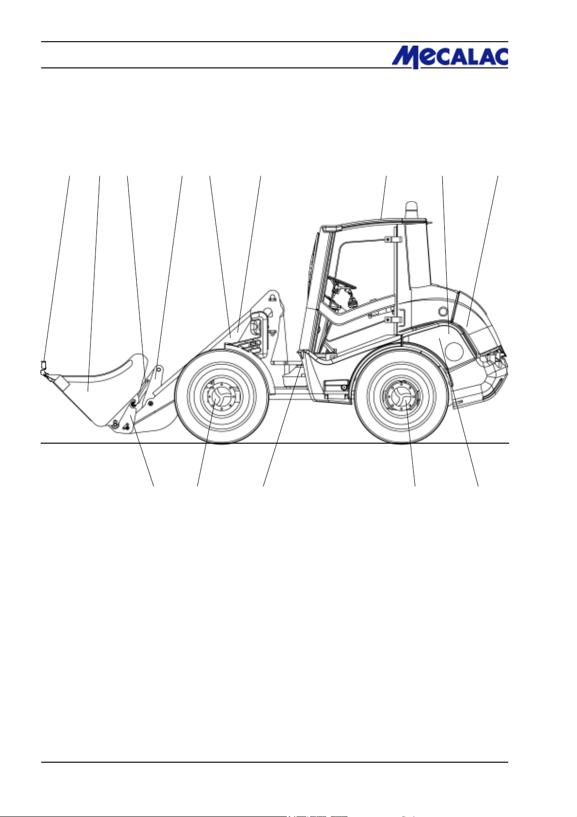
4.1 Overview
1 2 3 4 5 6 7 8 9
14 13 12 11 10
Figure 4-1
1 - Bucket protection
2 - Bucket/attachment
3 - Pivot arm
4 - Deflection lever
5 - Bucket arm
6 - Tip cylinder (in the bucket arm)
7 - Driver’s cab
8 - Hydraulic oil tank (right loader side underneath the engine hood)
9 - Drive motor
10 - Fuel tank (left loader side underneath the engine hood)
11 - Rear axle
12 - Articulated pendulum joint
13 - Front axle
14 - Quick-change device
20
P0700/P0710/P0850/P0860/P1000/P10104-2
Page 31
4.2 Loader
Undercarriage
The axial piston pump for the hydraulic drive is driven by
the diesel engine. Pressure hoses for extremely high
pressure connect the axial piston pump with the axial piston
engine. The axial piston engine is flanged to the distribution/
intermediate gear of the rear axle (with planetary gear). The
distribution/intermediate gear transmits the torque of the
axial piston engine directly to the rear axle and to the front
axle (with planetary gear).
CAUTION
The maximum speed of the axial piston engine is
governed by settings made at the factory. Any
adjustment will render the warranty invalid.
Tyres
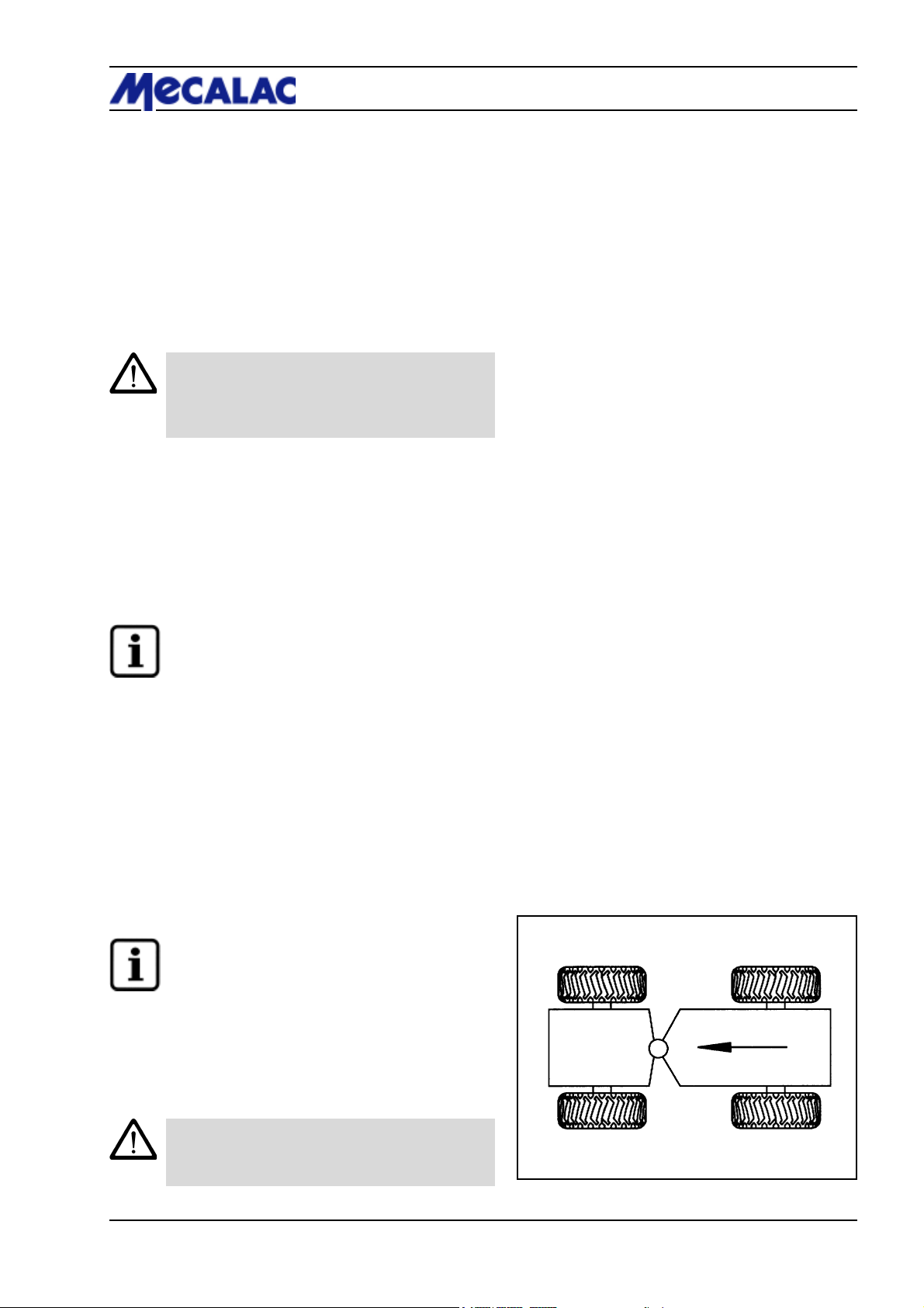
The following tyres are permitted:
Description 4
12.5/80 R18 15.5/55 R18 365/70 R18
405/70 R18 425/55 R17
For the running direction, see Fig. 4-2.
NOTE
All four tyres must be identical and have the same
PR rating (PR = ply rating: number of textile plies).
Steering system
The power for the hydrostatic steering system is supplied
via a priority valve from a gear-type pump. With a minimum
of effort on the steering wheel, the oil flow is directed by a
steering unit into the steering cylinder.
Emergency steering
The hydrostatic steering system can also be used in a
limited way if the diesel engine fails. The loader can be
steered using a considerable amount of manual effort.
NOTE
See chapter 7, “Towing the loader”.
Differential lock
To enhance the traction of soft slippery ground, you can
enable the differential lock acting on all four wheels by
pressing pushbutton (4-10/10) and keeping it pressed.
CAUTION
Enable the differential lock only when the loader
is at a standstill.
Figure 4-2
P0700/P0710/P0850/P0860/P1000/P1010 4-3
Page 32

4 Description
Figure 4-3
Make sure the differential lock engages by releasing the
accelerator and steering movements if only one wheel of
an axle rotates with the differential lock enabled.
You may disable the differential lock while the loader is
moving.
CAUTION
Make sure to disable the differential lock when
driving on solid ground, in particular when taking
bends.
Service brake/ inching
AX 700/20 km/h and AX 850/20 km/h:
The loaders are equipped with a hydraulic drum brake in
the front axle acting on all four wheels.
AX 700/30 km/h, AX 850/30 km/h and AX 1000:
The loaders are equipped with a hydraulic disc brake in the
front axle acting on all four wheels.
The service brake is actuated with a pedal (4-3/arrow)
located to the left of the steering column. It is supported by
the hydrostatic traction drive (inching), i.e. during work,
the drive pedal is used for accelerating and braking.
Figure 4-4
Parking brake
The parking brake is actuated with a hand lever
(4-4/arrow) located to the left of the driver’s seat.
When actuated, the mechanic parking brake acting on all
four wheels switches off the traction drive.
Fuel supply system
The fuel tank is located on the left-hand side of the loader
rear. An electrical fuel gauge (4-11/23) in the operator’s
cabin monitors the fuel level in the tank. The filler neck
(4-5/arrow) is located beneath the engine hood on the left
loader side.
Air filter device
Dry air filter system with safety cartridge (opt.) and
umbrella valve.
Lift and tip devices
Via a servo valve a double-acting gear-type pump drives
- two lifting cylinders
- one tip cylinder
Figure 4-5
All movements of the bucket arm, the bucket, the attachments and the quick-change device are controlled from the
driver’s seat by pilot valves.
These pilot valves provide continuous speed control from
“slow” to “fast”.
P0700/P0710/P0850/P0860/P1000/P10104-4
Page 33
Float position
The loader features a floating position. It is activated by
moving the hand lever (4-8/4) beyond its pressure point to
the frontmost position. The hand lever remains engaged in this
position until it is pulled back.
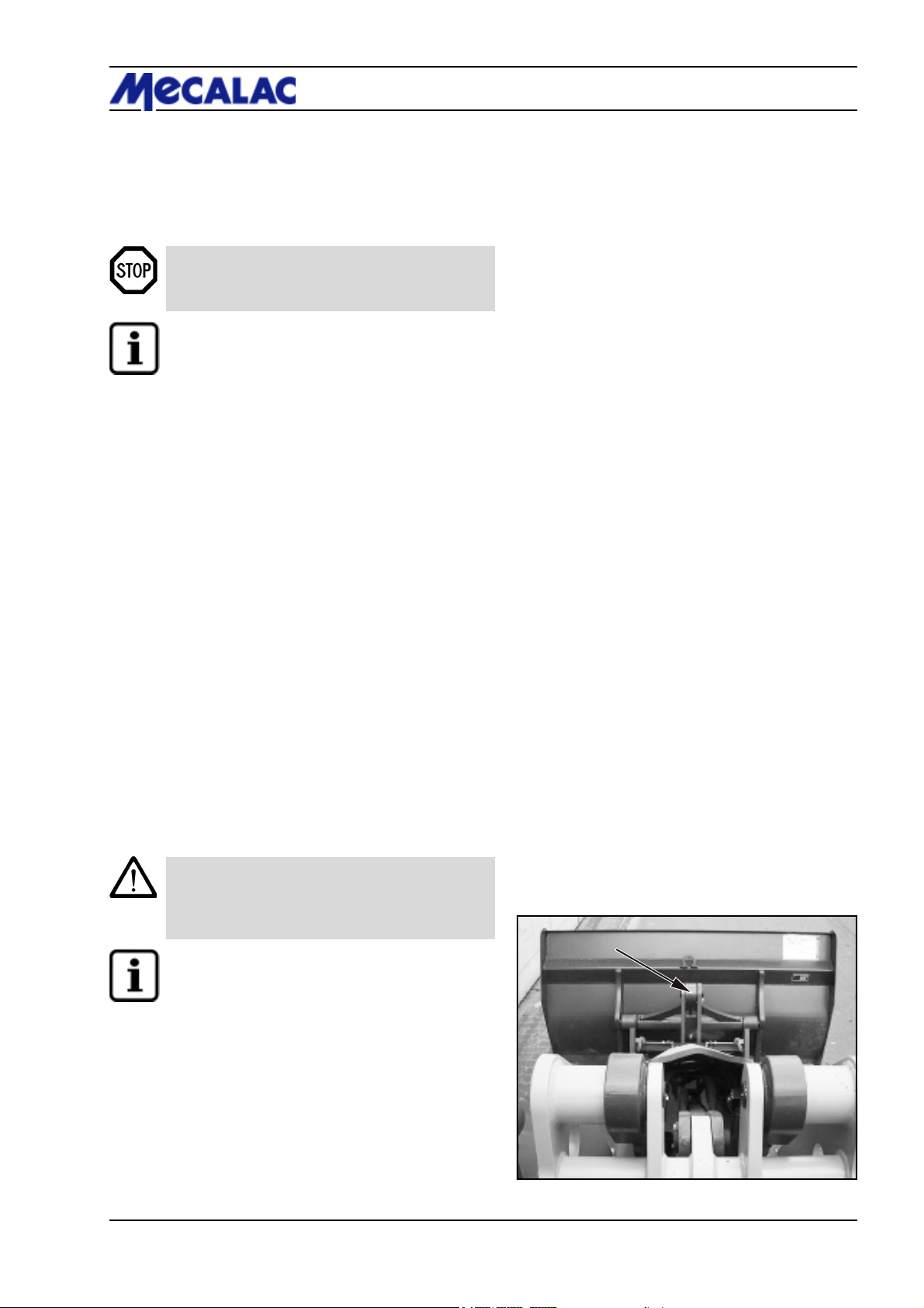
DANGER
The float position may only be activated when the
bucket arm is in the lowermost position.
NOTE
- The float position is disabled if the loader is
equipped with a pipe break protection.
- You can disable the pipe break protection
(4-10/16) to maintain the function of the float
position (option).
Pipe break protection(option)
A pipe break safety valve is installed at the bottom of each
tip and lift cylinder. In the event of a pipe or hose break in
the lift and/or tip system, the movements of the bucket arm
and the tipping rod are blocked until the damage is
repaired.
The pipe break protection can be enabled or disabled
(4-10/16) (option).
Description 4
Lifting device suspension (option)
When the loader must be driven over larger distances,
especially with a loaded bucket, the lifting device suspension
(4-10/15) should be activated to avoid resonant motion.
This becomes even more important with increasing
unevenness of the terrain and increasing speed of the
loader.
CAUTION
The lifting device suspension must only be used
for driving over long distances, not for working
with the loader.
NOTE
- The lifting device suspension is disabled if the
loader is equipped with a pipe break protection.
- You can switch off the pipe break protection
(4-10/16) (option) to maintain the function of the
lifting device suspension.
Bucket position indicator
The driver can see the position of the bucket by the
coloured markings on the pivot arm and the reversing lever.
When the coloured marks (4-6/arrow) form a line, the
bucket floor is parallel to the ground.
Figure 4-6
P0700/P0710/P0850/P0860/P1000/P1010 4-5
Page 34
4 Description
4.3 Wheel change
DANGER
Before changing a wheel on public roads, the
danger area must be properly marked.
(1) Park the loader on solid ground and not on inclines if
possible.
(2) Lower the attachment to the ground.
(3) Set the drive switch (4-10/11) to “0”.
(4) Apply the parking brake (4-9/3).
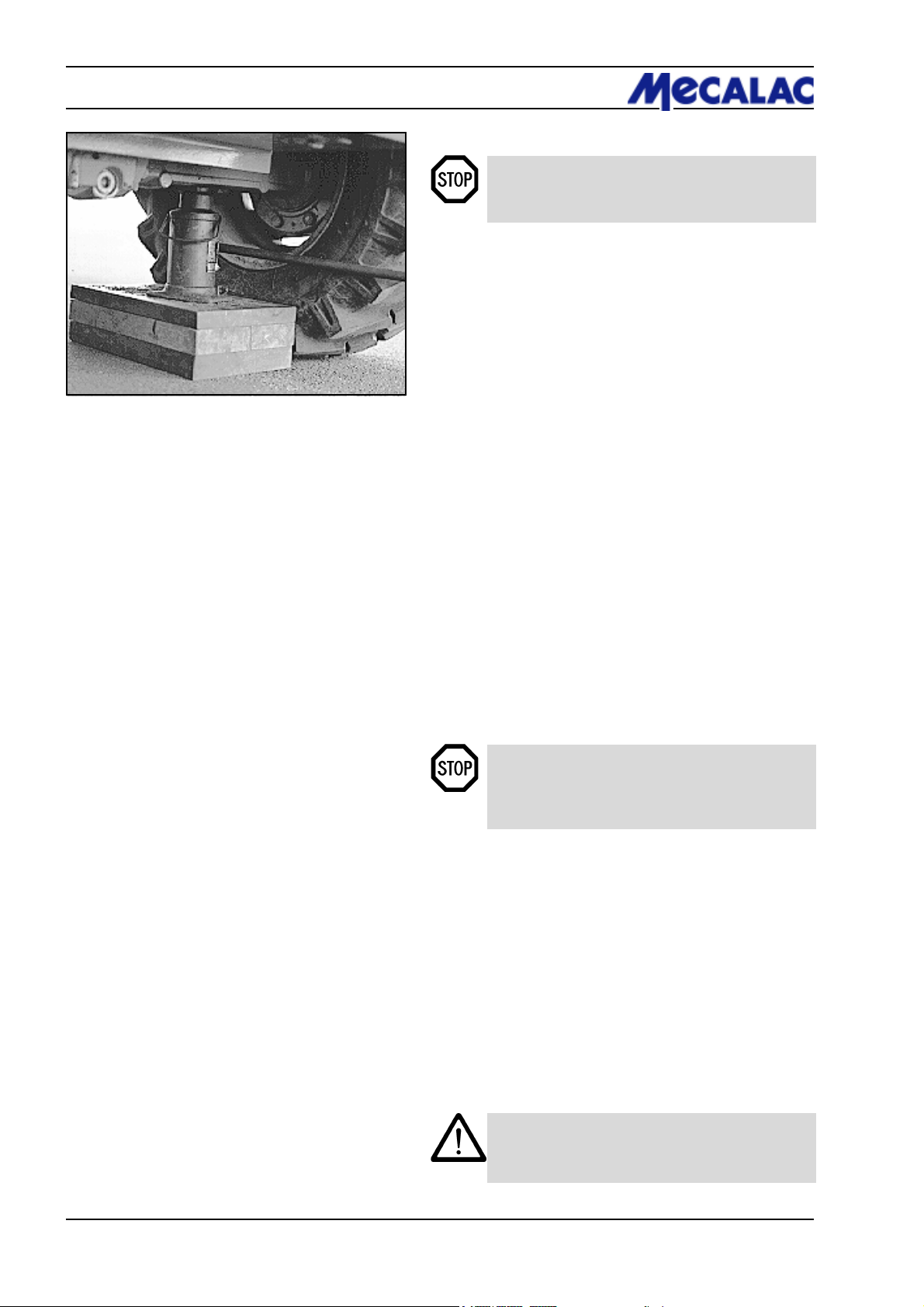
Figure 4-7
(5) Turn the ignition key to the left to position “0” (5-1).
(6) Lock (4-8-/6) pilot valves for the working and auxiliary
hydraulics (4-8/4 and 4-8/5).
(7) Insert the articulation safeguard into the articulation
joint (1-3/arrow).
(8) Secure the machine by placing two wedges under one
wheel of the axle where no wheel is to be changed.
(9) Loosen the wheel nuts of the wheel to be changed so
that they can be turned manually.
(10) Fit a suitable jack (minimum capacity 3.0 tons) from
the side under the axle bridge in the vicinity of the axle
fixture so that it is centred and cannot slip (4-7). Lift the
front/rear axle until the wheel does not have any contact to
the ground.
DANGER
- Secure the jack by a suitable support to prevent
it from sinking into the ground.
- Make sure that the jack is fitted well.
(11) Loosen the wheel nuts completely and remove them.
(12) Lower the loader slightly with the jack until the wheel
bolts are free.
(13) Push off the wheel from the wheel hub by moving it
back and forth. Remove the wheel and roll it aside.
(14) Mount the new wheel onto the planetary axle.
(15) Tighten the wheel nuts by hand.
(16) Lower the front/rear axle using the jack.
(17) Tighten the wheel nuts with a torque wrench (440 Nm).
CAUTION
Retighten the wheel nuts after the first 8-10
operating hours.
P0700/P0710/P0850/P0860/P1000/P10104-6
Page 35
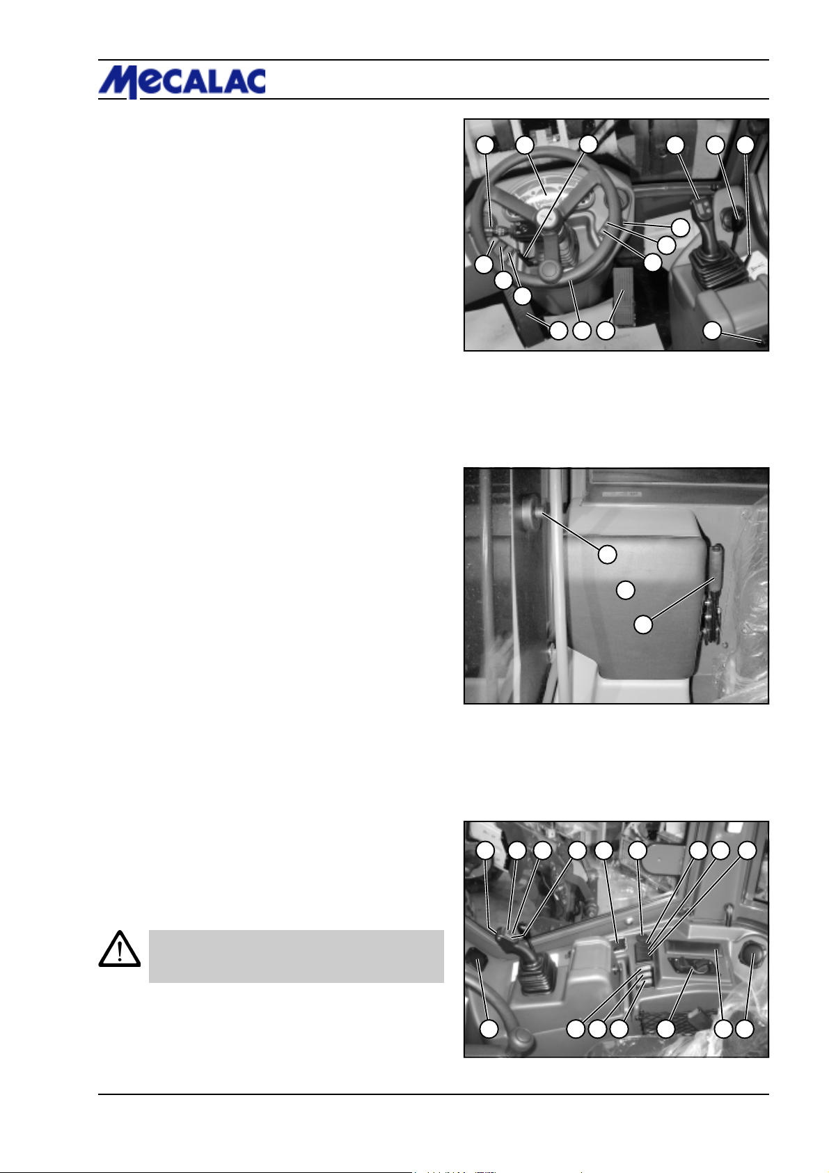
4.4 Controls
1 - Steering column switch
- to the front: Turn signal, right
- to the rear: Turn signal, left
- up: Low beam
- down: High beam
- Pushbutton: Signal horn
- Turn, step 1: Interval wiper, front
- Turn, step 2: Windshield wiper, front
- Push upper ring in axial direction:
Windshield washer, front
2 - Multifunction panel
3 - Lock lever for steering column adjustment
- to the front/rear
- in axial steering column direction
4 - Pilot valve for working hydraulics
5 - Pilot valve for auxiliary hydraulics
6 -
Lock lever pilot valve for working and auxiliary hydraulics
7 - Starter switch
8 - Accelerator
9 - Steering wheel
10 - Foot pedal for service brake/ inching
11 - free
12 - free
13 - Toggle switch for hazard flasher system
14 - Toggle switch for road lights
- Position I: Parking light
- Position II: Road light
15 - Toggle switch for windshield wiper/washer, rear
- Position I: Wiper
- Position II:
16 - Pushbutton for releasing the quick-change device
Wiper/washer (pushbutton function)
1 2
11
12
13
Figure 4-8
Description 4
3
16
15
14
10 8 79
1
2
54
6
To the left of the driver’s seat:
1 - Door release
2 - Foldable emergency seat (option) (see chapter 4.4.2)
3 - Hand lever for parking brake
To the right of the driver’s seat:
1 - Loudspeaker
2 - Radio
3 - Heating/air condition
4 - Toggle switch for rear window heater
5 - Toggle switch for beacon light (opt.)
6 - Toggle switch for working lights
9 - Hydraulic drive levels:
- right - Stage I: slow
- left - Stage II: fast
10 - Two parallel pushbuttons for differential lock
- Pushbuttons pressed:
Differential lock enabled
- Pushbuttons not pressed:
Differential lock disabled
CAUTION
The differential lock may only be enabled when
the loader is not moving.
11 - Drive switch: forward/0/reverse
12 - Ash tray
13 - 2-pole socket
14 - Toggle switch for permanent auxiliary hydraulics (opt.)
15 - Toggle switch for lifting device suspension (opt.)
16 - Toggle switch for pipe break protection (opt.)
Figure 4-9
1
Figure 4-10
3
1010
1615141312119
123456
P0700/P0710/P0850/P0860/P1000/P1010 4-7
Page 36
4 Description
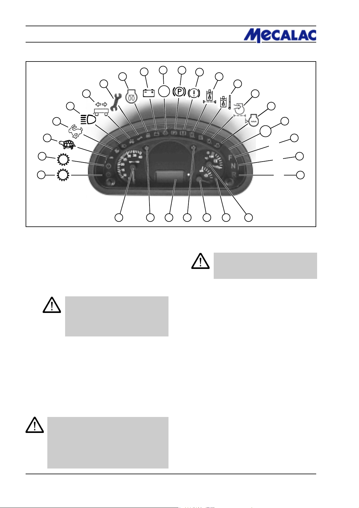
4.4.1 Multifunction panel (4-8/2)
3
2
1
Figure 4-11
10
8
7
6
5
4
9
11
12
13
14
15
16
17
18
F
1°
2°
N
R
222324252627
21
19
20
1 - free
2 - free
3 - Indicator lamp: Hydraulic drive stage „slow“
4 - Indicator lamp: Hydraulic drive stage „fast“
5 - Indicator lamp: High beam
6 - free
7 - Signal lamp: Engine Stop
CAUTION
The controller detected a severe engine
fault.
Shut off the engine immediately!
Have an expert investigate the fault.
8 - Indicator lamp: Preheating
9 - Battery charge indicator
10 - free
11 - Indicator lamp: Parking brake
4.4.2 Emergency seat (foldable) (4-9/2)
CAUTION
A passenger may only sit down on the widened
part of the emergency seat in order to safely
reach the grab handle installed on column A.
12 - Indicator lamp: Engine Warning
CAUTION
The controller detected an engine fault.
Have an expert investigate the fault.
13 - Hydraulic oil filter clogging indicator (opt.)
14 - Signal lamp: Hydraulic oil temperature
15 - Air filter clogging indicator (opt.)
16 - Signal lamp: Low cooling water
17 - Indicator lamp: Differential lock
18 - Indicator lamp: Travel direction “forward“
19 - Indicator lamp: Travel direction “0-position“
20 - Indicator lamp: Travel direction “reverse“
21 - Cooling water temperature gauge
22 - Indicator lamp: Fuel on reserve
23 - Fuel gauge
24 - Indicator lamp: Turn signal „right“
25 - Operating hours counter and digital clock
26 - Indicator lamp: Turn signal „left“
27 - Rev meter
In this position he will not limit the driver’s free
moving space.
P0700/P0710/P0850/P0860/P1000/P10104-8
Page 37
Description 4
Type 1
7
1 2 3 4 5 6 7 8 9 10 11 12 13 14
G1 G2 K1 K2 XC K4 K5 K6 K7 K8
1
2
3
4
5
6
Figure 4-12
Figure 4-13
4.4.3 Opening the window
1. Opening the window:
First pull the window handle inwards, then push it outwards.
Finally lift the window handle out of its holder.
2. Opening and locking the window :
First pull the window handle inwards, then push it outwards.
Finally pull the window handle to the rear until it locks.
4.5 Fuses/relays
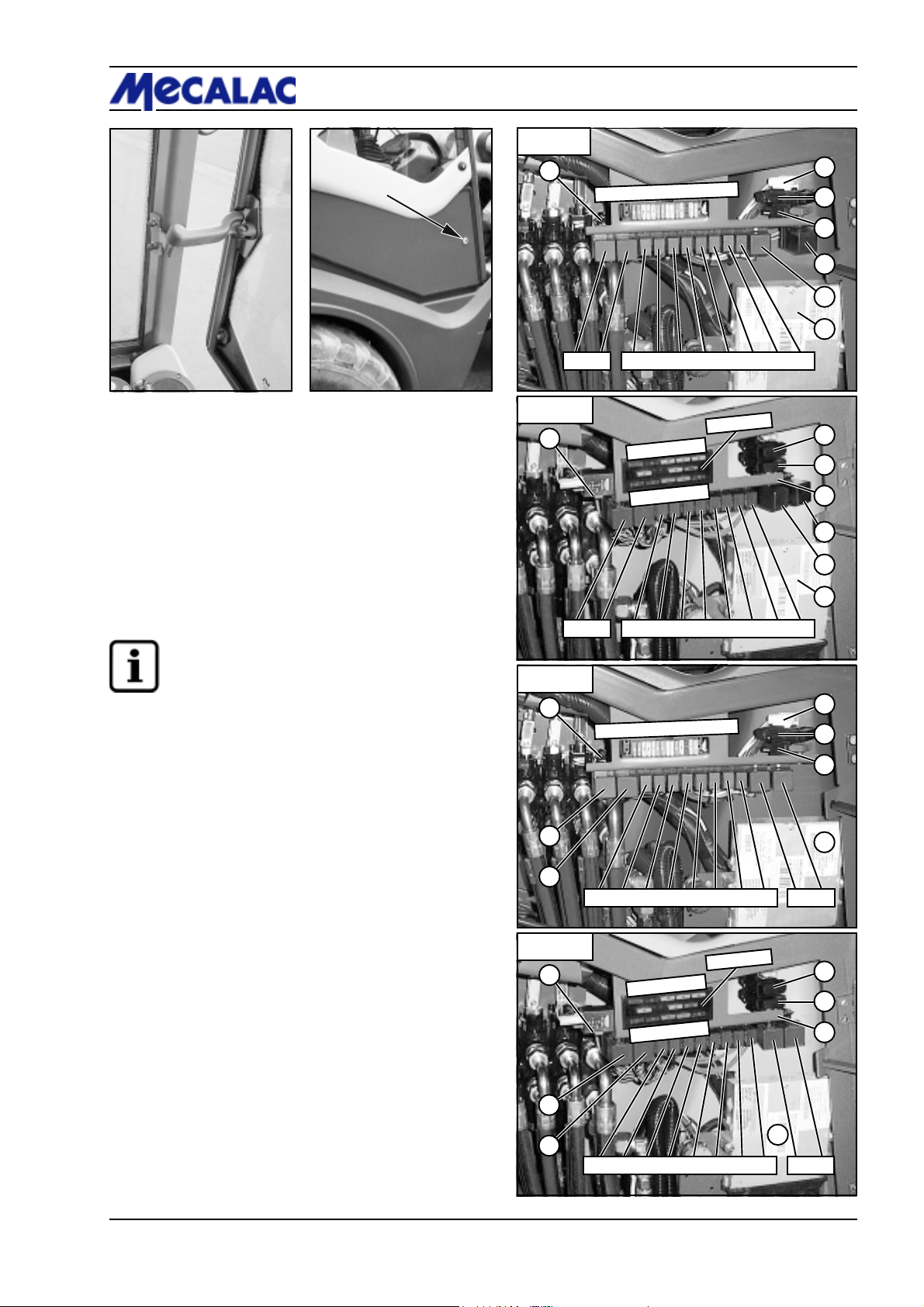
NOTE
Fuses, relays, turn signal relay, interval relay etc.
(4-14) are located behind the maintenance flap on
the right side of the loader (4-13/arrow).
G1 - Interval timer
G2 - Turn signal relay
1 - Fuse (controller engine) 20.0 A
2 - Maxi fuse (power supply) 100.0 A
3 - Maxi fuse (glow plugs) 100.0 A
4 - Glow start system relay
5 - Maxi relay (power supply)
6 - Controller engine
7 - Acoustic buzzer, hydraulic oil temperature
Fuses:
1 - Traction drive 10.0 A
2 - Turn indicator 7.5 A
3 - Hydraulics/brake light 20.0 A
4 - Heater 20.0 A
5 - Rear window heater 20.0 A
6 - High beam 15.0 A
7 - Low beam 15.0 A
8 - Parking light, left 5.0 A
9 - Parking light, right 5.0 A
10 - Hazard flasher 15.0 A
11 - Windshield wiper/washer 20.0 A
12 - Free
13 - Working lights 20.0 A
14 - Warning beacon (opt.) 30.0 A
Relays:
K1 - Differential lock
K2 - Fan control
XC - Controller engine (ECU)
K4 - Traction drive cut-out
K5 - Power control: reverse
K6 - Power control: forward
K7 - Alpha max.
K8 - Start-up interlock
Type 2
7
G1 G2 K1 K2 XC K4 K5 K6 K7 K8
Type 3
7
1 2 3 4 5 6 7 8 9 10 11 12 13 14
5
4
K1 K2 K4 K5 K6 K7 K8 XC
Type 4
7
5
4
K1 K2 K4 K5 K6 K7 K8 XC
Figure 4-14
Bild 4-14
11 12 13 14
1 2 3 4 5
6 7 8 9 10
11 12 13 14
1 2 3 4 5
6 7 8 9 10
1
2
3
4
5
6
1
2
3
6
G1 G2
1
2
3
6
G1 G2
P0700/P0710/P0850/P0860/P1000/P1010 4-9
Page 38
4 Description
Figure 4-15
4.6 Removing the driver’s cab
NOTE
- Park the loader on solid and level ground.
- The engine must be turned off.
- Unlock the battery main switch (opt.) (8-36/1)
by giving it 2 counter clockwise turns.
- Immobilise the loader with the parking brake
(4-9/3).
- Have 4-strand lifting gear ready.
CAUTION
- Remove the driver’s cabin with the loader
standing horizontally and the bucket arm in the
lowest position.
- Use the intended mounting aids or other secure
working platforms when performing work above
reaching height. Do not use any loader parts, in
particular attachments, as climbing or
descending aids. Use safety harnesses when
working at very great heights.
- Use a crane capable of precisely lifting the load
in vertical direction for the conversion.
Figure 4-16
(1) Dismount the left driver’s cab door.
(2) Dismount the upper window section on the right loader
side (see also chapter 4.5. NOTE).
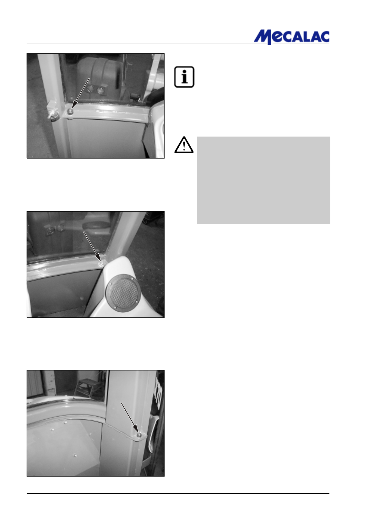
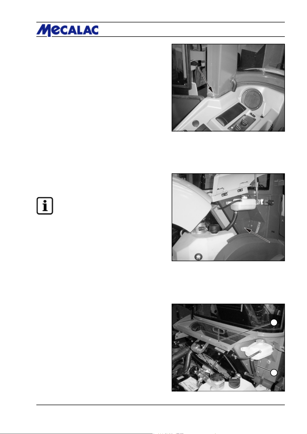
(3) Loosen the connecting screws between driver’s cab
lower and upper section at the front left (4-15/arrow) and
right (4-16/arrow).
(4) Loosen the connecting screws between driver’s cab
lower and upper section at the rear left (4-17/arrow) and
right (4-18/arrow).
Figure 4-17
P0700/P0710/P0850/P0860/P1000/P10104-10
Page 39
(5) Open the right maintenance flap, take out any wedge
that may be present and dismount the service plate (4-19/
arrow or 4-20/2).
Description 4
Figure 4-18
NOTE
Open the engine hood before opening the
maintenance flap.
(6) Loosen the screw (10 mm Allen key) connecting the
driver’s cab lower and upper section at the rear in the
middle of the cooler intake duct (4-20/1), accessible
through the maintenance opening (4-19/arrow or 4-20/2).
Figure 4-19
1
2
Figure 4-20
P0700/P0710/P0850/P0860/P1000/P1010 4-11
Page 40
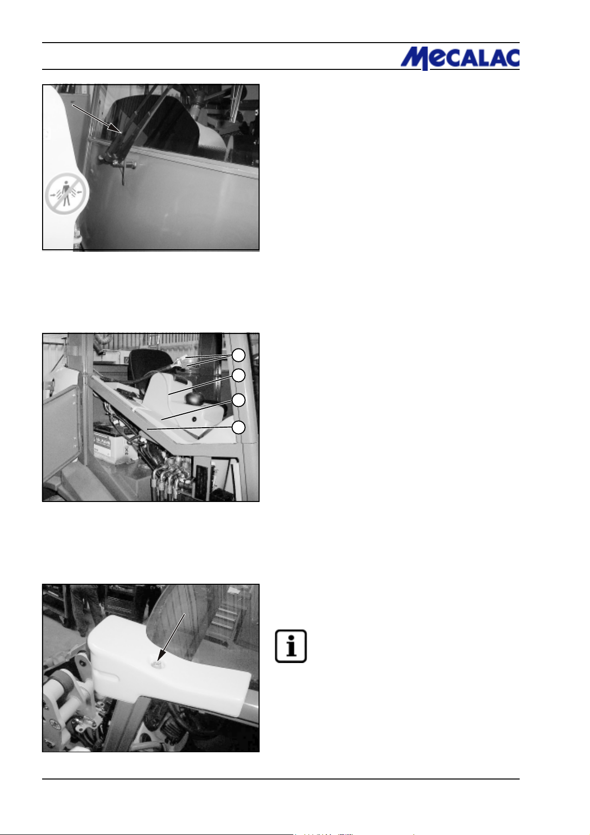
4 Description
Figure 4-21
(7) Unscrew the front windshield wiper arm (4-21/arrow)
and pull it off the wiper motor shafts.
(8) Loosen the covering (4-22/3) from the frame of the
1
2
3
maintenance flap (4-22/4).
- Break the electrical connection (X11) (4-22/1).
- Unplug the hose leading to the compensation tank for
coolant (4-22/2) from the adapter.
Pull electrical connector and hose as shown in Fig. 4-22
upwards into the driver’s cab upper section.
Figure 4-22
4
(9) Loosen the fastening screw for the working light cover
plate (4-23/arrow) on the driver’s cab at the front left and
right and take off the cover plate.
NOTE
Support the working lights. One screw fastens
both the working lights and the cover plates.
(10) Loosen the fastening screws at the rear left and right
of the driver’s cab each.
Figure 4-23
P0700/P0710/P0850/P0860/P1000/P10104-12
Page 41
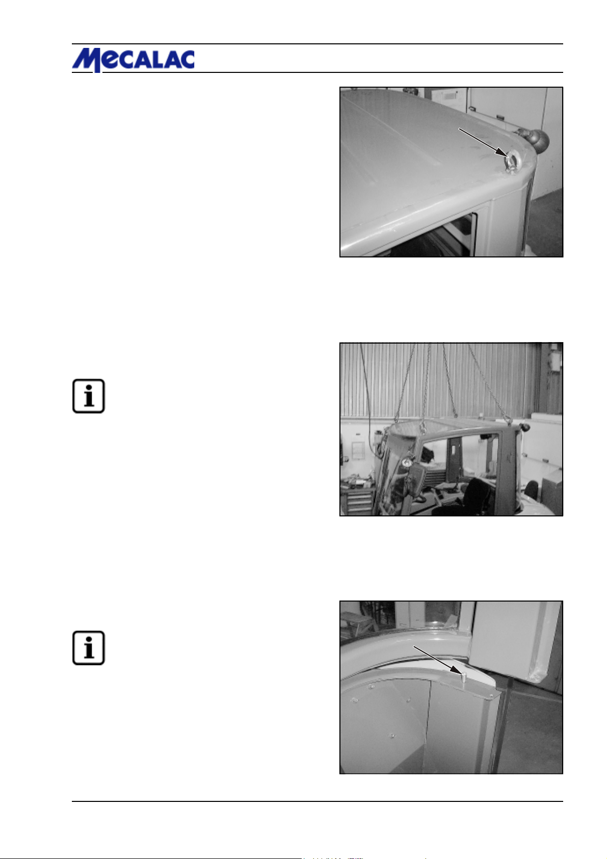
(11) Screw in four lifting eyes (4-24/arrow).
(12) Attach 4-strand lifting gear into the crane lifting eyes
(4-25).
Description 4
Figure 4-24
NOTE
The two rear strands of the lifting gear must be
approx. 10 cm shorter than the front strands.
(13) Slowly lift the driver’s cab until the two rear index pins
(4-26/arrow and 4-27/arrow) are free.
NOTE
The driver’s cab front must not yet be raised.
Figure 4-25
Figure 4-26
P0700/P0710/P0850/P0860/P1000/P1010 4-13
Page 42
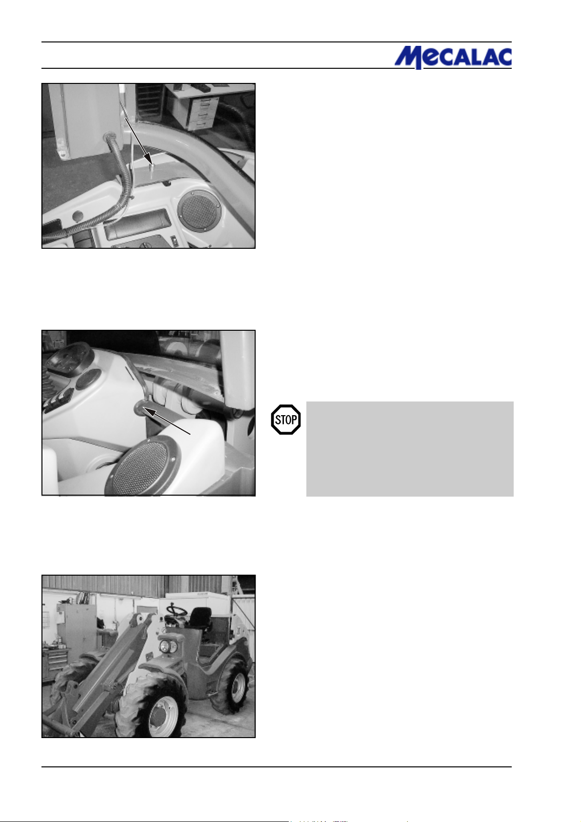
4 Description
Figure 4-27
(14) Pull the driver’s cab forward with your hand until it
comes free off the recess in the dashboard in the lower
windshield area (4-28/arrow).
Figure 4-28
(15) Lift driver’s cab until it can be swivelled over the
steering wheel.
DANGER
Never stand or work underneath the suspended
load. The lifting device (crane) operator maintains
eye contact with the assigned helpers and decides
on when and how they take action. The operator
(of the crane for example) makes sure no
hazardous movements take place when helpers
are in the danger area.
Figure 4-29 shows the loader with removed driver’s
cab.
Technical data (exhaust in the counterweight):
- Tyres: 12.5-80, profile AT 603 (3.0 bar)
- Height over driver’s seat: 1,825 mm
- Height over steering wheel with knob: 1,870 mm
- Height over steering wheel without knob: 1,810 mm
- Weight of upper cabin section
(without door/without right side window): 122 kg
Figure 4-29
P0700/P0710/P0850/P0860/P1000/P10104-14
Page 43

Operation
Page 44
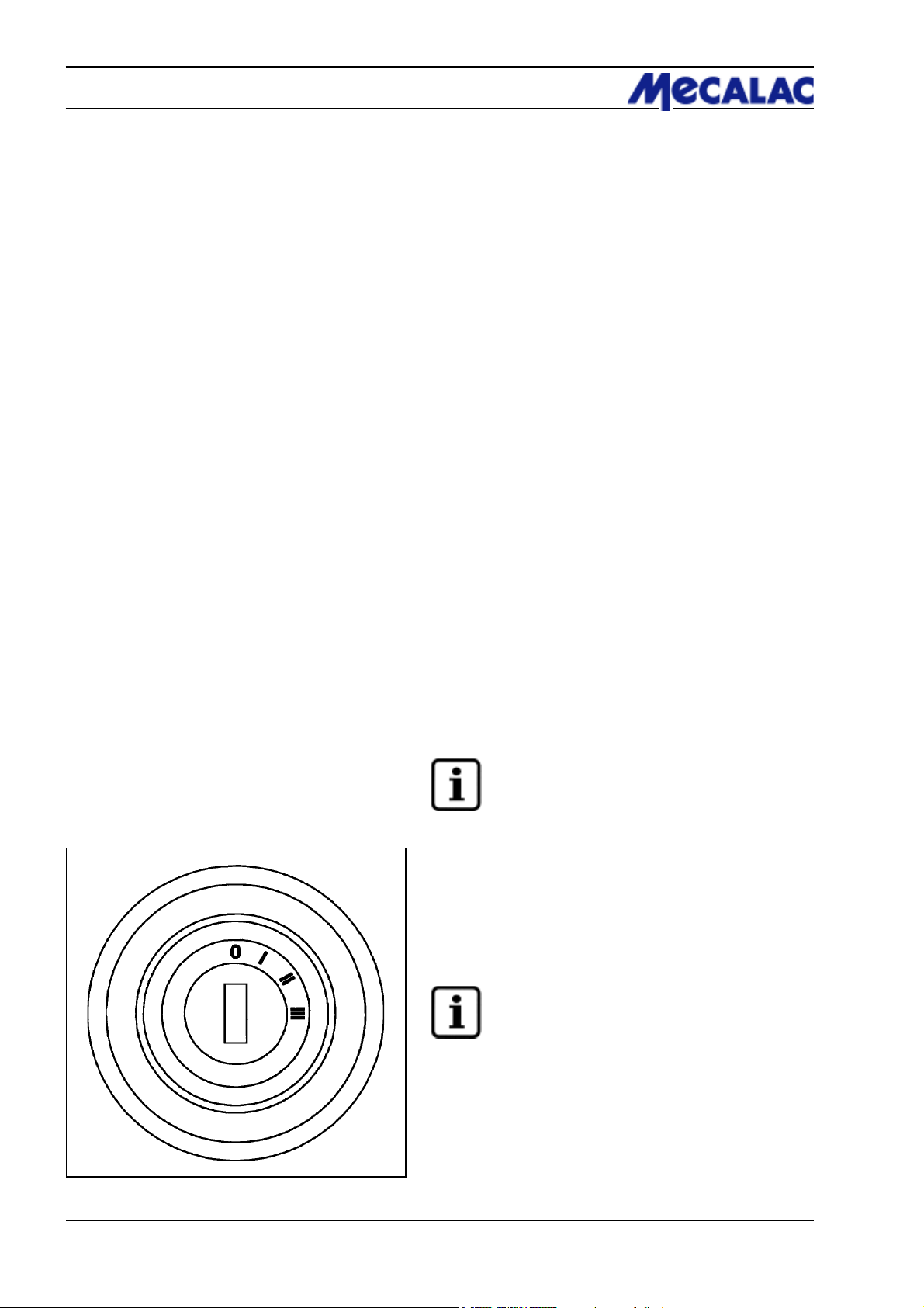
5 Operation
5 Operation
5.1 Checks before start-up
- Engine oil level (see the operating instructions for the engine)
- Brake fluid (brake hydraulic oil)
- Hydraulic oil level
- Fuel level
- Tyre pressure
- Profile depth
- Lighting system
- Seat position
- Remove the lock levers for the auxiliary and working
hydraulics pilot valves (4-8/6) if present
» only if work is to be commenced «
- Bucket arm prop [(e.g. bucket arm support (option)
(1-2/arrow)]; remove if necessary
- Articulation safeguard (1-3/arrow); remove if necessary
- General state of the loader, e.g. check for leaks
- The presence of
- a fist aid kit
- a warning triangle
- a signal lamp
must be verified.
Figure 5-1
5.2 Start-up
5.2.1 Starting the diesel engine
(1) Apply the parking brake (4-9/3).
(2) Set the drive switch (4-10/11) to “0” (starter interlock!).
(3) Turn the main battery switch (8-36/1) clockwise to the
stop.
(4) Insert the ignition key into the starter switch (4-8/7)
and turn the key clockwise to position "II“ (5-1).
NOTE
- Indicators for battery charge, parking brake,
engine oil pressure and preheating light up. The
fuel gauge, the coolant temperature gauge, the
operating hour counter and the digital clock
function.
- Start the engine in position "0“ of the drive
switch (4-10/11).
(5) Turn the ignition key clockwise to position "III“ (5-1)
after a few seconds (preheating). As soon as the engine
starts, release the ignition key.
NOTE
- If the engine has not started after two attempts,
determine the cause using the malfunction table
in the operating instructions for the engine.
- For operation at extremely low temperatures,
see the operating instructions for the engine.
- Run the engine at a low speed and do not subject
it to full load until the hydraulic oil has reached its
operating temperature after a cold start.
When a hydraulic oil filter clogging indicator
(4-11/13) (option) is present, it will go out as soon
as the hydraulic oil has reached its operating
temperature.
P070/P071/P085/P086/P100/P1015-2
Page 45
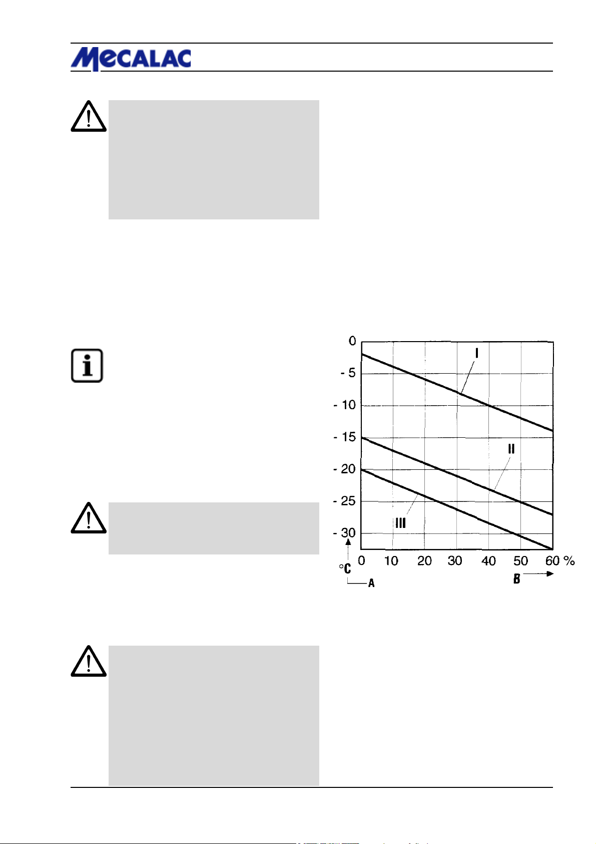
5.2.2 Winter operation
CAUTION
If the outside temperature is below 0 °C, the
machine must be properly „warmed up“ to avoid
damage to certain assemblies. To do so, actuate
all cylinders (lifting and tipping cylinders) for
some time (depending on the ambient temperature) with the machine idling.
Proper operation of the machine, even for subzero temperatures, can only be guaranteed if the
following measures have been taken:
5.2.2.1 Fuel
At low temperatures, paraffin precipitating from the fuel
can cause the fuel system to clog up.
For this reason, always use winter diesel fuel (suitable for
temperatures down to -15 °C) when the outside temperature is below 0 °C.
Operation 5
NOTE
The fuelling stations normally start offering winter
diesel fuel in good time before the cold season
starts. Often, they offer diesel fuel that can be
used down to temperatures of -20 °C (supergrade diesel fuel).
If the temperature is below -15 °C or -20 °C,
paraffin oil must be added to the diesel fuel. For
the mixture ratio, refer to the diagram (5-2).
I = Summer diesel fuel
II = Winter diesel fuel
III = Super-grade diesel fuel
CAUTION
Only mix the ingredients in the tank! First, fill in the
required amount of paraffin oil, then top up with
diesel fuel.
5.2.2.2 Engine oil change
See the operating instructions for the engine.
5.2.2.3 Hydraulic system oil change
CAUTION
The viscosity of the hydraulic oil changes according to the temperature; therefore, the ambient
temperature in the place where the machine will
be used determines what viscosity class (SAE
class) must be chosen. If the hydraulic oil used
matches the expected ambient temperature,
optimum operating conditions can be attained.
Therefore, use hydraulic oil of an appropriate
grade if required.
See section 8.2.11 for the hydraulic system oil
change.
Figure 5-2
P070/P071/P085/P086/P100/P101 5-3
Page 46
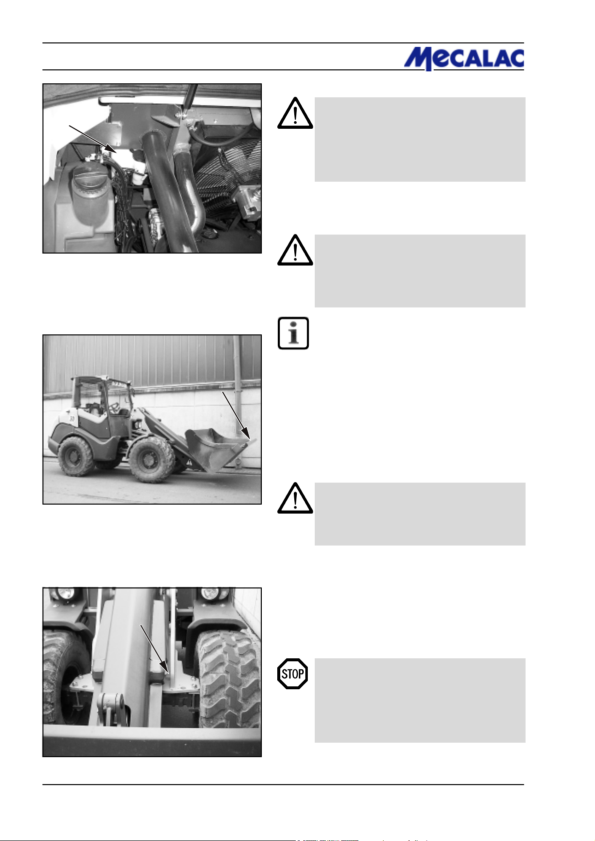
5 Operation
Figure 5-3
5.2.2.4 Anti-freezing agent, windshield washer
CAUTION
If the temperature is expected to drop below 0 °C,
add a sufficient amount of anti-freezing agent to
the water in the windshield washer system
(5-3/5) to prevent it from icing up.
For the mixture ratio, heed the instructions provided by the manufacturer.
5.2.3 Driving the loader on public roads
CAUTION
- Driving on public roads is only permitted with an
empty standard, multi-purpose or light-weight
material bucket and only with bucket protection.
- A warning triangle and a first-aid kit must be
provided in the loader.
NOTE
The driver of the loader must possess a valid
driver’s license equivalent to class "C1“.
The driver must carry his driver’s license (original)
and the operating permit (original) with him.
Figure 5-4
Before driving on public roads, the following safety measures
must be taken:
(1) Lower the bucket arm until the lowest point of the
bucket arm or the bucket is at least 30 cm above the road
(5-4).
(2) Lock (4-8-/6) pilot valves for the working and auxiliary
hydraulics (4-8/4 and 4-8/5) by setting them to the rear.
CAUTION
Locking the two pilot valves prevent inadvertent
lowering of the bucket arm, inadvertent tilting up
or dumping or inadvertent opening of the bucket
while travelling.
(3) Cover the bucket cutting edge and teeth with the
bucket protector (5-4/arrow).
(4) Insert the plug of the bucket protector into the socket
(5-5/arrow, option).
(5) Perform a function check.
(6) Lock both doors.
DANGER
- Driving on public roads with the bucket filled is
forbidden.
- The differential lock (4-10/10) must not be
enabled when driving on public roads.
- The working lights must be switched off
(4-10/6).
Figure 5-5
P070/P071/P085/P086/P100/P1015-4
Page 47
(7) Release the parking brake (4-9/3).
(8) Preselect hydraulic drive stage II (4-10/9).
(9) Select the travel direction (4-10/11).
(10) Press the accelerator pedal (4-8/8).
NOTE
- The loader starts. The travel speed is determined
by the position of the accelerator pedal.
- The service brake is activated by depressing
the brake pedal (4-8/11).
DANGER
Changing the travel direction during driving is not
allowed to avoid any danger to other road users.
5.2.4 Working with the loader
Operation 5
Generally, all work is carried out in hydraulic stage II
(4-10/9).
For special tasks which ask for a more sensitive control of
the speed or a higher engine speed at reduced travel
speed, hydraulic drive stage *I“ (4-10/9) can be selected.
The travel speed can thus be reduced to 7 km/h.
To attain full performance, the combined action of propulsion and of the working hydraulics is necessary. It is up to
the operator to control the available power using the
accelerator, the inching function and the hand lever for the
working hydraulics.
NOTE
The hydraulic drive stage can be switched from
I to II or vice versa while driving. However,
switching from drive stage II to I is not recommended when driving at high speeds since the
loader is then braked very abruptly.
(1) Lock both doors.
(2) Release the parking brake (4-9/3).
(3) Preselect hydraulic drive stage (4-10/9).
(4) Select the travel direction (4-10/11).
(5) Press the accelerator pedal (4-8/8).
NOTE
- The travel speed and the thrust force are altered
exclusively by depressing the accelerator pedal.
- When driving up gradients, the travel speed
decreases in spite of full throttle in favour of the
thrust force.
- The thrust forces and travel speeds are the
same in the forward and the reverse direction.
P070/P071/P085/P086/P100/P101 5-5
Page 48
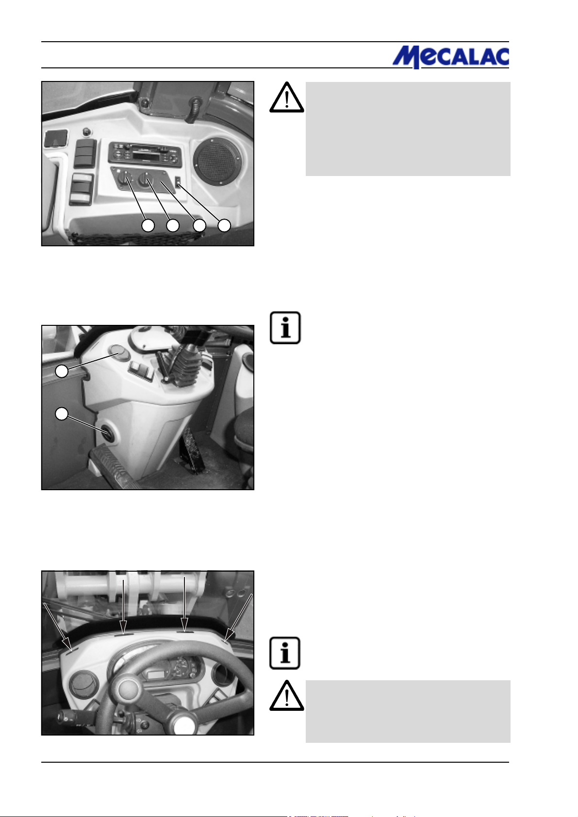
5 Operation
CAUTION
- The hydraulic quick-change device must only
be locked if an attachment has been mounted.
- If the hydraulic oil temperature indicator lamp
(4-11/14) lights up during operation, the loader
must be switched off immediately, the cause
must be determined by a hydraulics expert and
the malfunction must be eliminated.
5.2.5 Heating and ventilation system
Figure 5-6
1
2
Figure 5-7
21 43
5.2.5.1 Setting the air flow
(1) Turn the rotary switch (5-6/1) for the blower to position
0, 1, 2, or 3 depending on the air flow desired.
(2) Set the air flow direction with the air outlet nozzles to
the right and left of the steering column/dashboard (5-7/1
and 5-7/2).
NOTE
There are also four invariable air nozzles in the
windshield area (5-8/arrows).
5.2.5.2 Switching on the heater
(1) Turn the knob (5-6/2) in the clockwise (cold) or the
anti-clockwise direction (warm) to reach the desired
temperature.
5.2.5.3 Switching on the air condition (opt.)
(1) Press the „ON/OFF“ switch (5-6/4) to control the air
condition as desired.
Switch pressed in the upper half - Air condition "OFF“
Switch pressed in the lower half - Air condition "ON“
Figure 5-8
5.2.5.4 Setting the temperature
(1) The rotary switch (5-6/3) lets you control the temperature in the driver’s cabin.
Rotary switch in clockwise direction - colder
Rotary switch in counter clockwise direction - warmer
NOTE
The air condition is supplied via an air opening
behind the driver’s seat.
CAUTION
For safety instructions and pertaining disposal
regulations as well as for maintenance information,
refer to the operating instructions that come with
the air condition.
P070/P071/P085/P086/P100/P1015-6
Page 49
5.2.5.5 Voorruit ontdoen van ijs/aanslag
(1) Bij lopende motor (stationair toerental) aanjagerdraaischakelaar (5-6/1) in stand „3“ zetten.
(2) Onderste verstelbare uitstroomopeningen (5-7/2)
sluiten.
(3) Bovenste verstelbare uitstroomopeningen (5-7/1)
openen en luchtstroom op de voorruit richten.
AANWIJZING
Als de voorruit vrij is van aanslag respectievelijk
ijs, aanjagerdraaischakelaar in stand „2“ of „1“
zetten en onderste uitstroomopeningen eventueel
openen.
5.3 Decommissioning the loader
5.3.1 Parking the loader
(1) Stop the loader on solid ground; if possible, not on a
slope.
(2) Place the bucket or the attachment on the ground.
(3) Set the drive switch (4-10/11) to “0”.
(4) Apply the parking brake (4-9/3).
Operation 5
DANGER
If parking on a gradient cannot be avoided, wheel
chocks must be used and placed on the sloping
side of the front axle wheels in addition to applying
the parking brake, and the articulation safeguard
must be inserted. On slopes, the wheel chocks
must be placed on the sloping side of the rear axle
wheels.
5.3.2 Switch off the diesel engine
CAUTION
If the diesel engine is very hot or has been
subjected to heavy loads, let the engine idle for a
short time before switching it off.
Turn the ignition key to the left to position "0“ (5-1) and
remove the key.
5.3.3 Switching off the heater and ventilation system
(1) Shut off the hot air supply (5-6/2).
(2) Turn the rotary switch (5-6/1) for the blower to position
"0“.
5.3.4 Leaving the loader
(1) Lock (4-8-/6) pilot valves for the working and auxiliary
hydraulics (4-8/4 and 4-8/5) by setting them to the rear.
(2) Unlock the battery main switch (opt.) (8-36/1) by
giving it 2 counter clockwise turns.
(3) Remove the ignition key and lock the doors.
P070/P071/P085/P086/P100/P101 5-7
Page 50
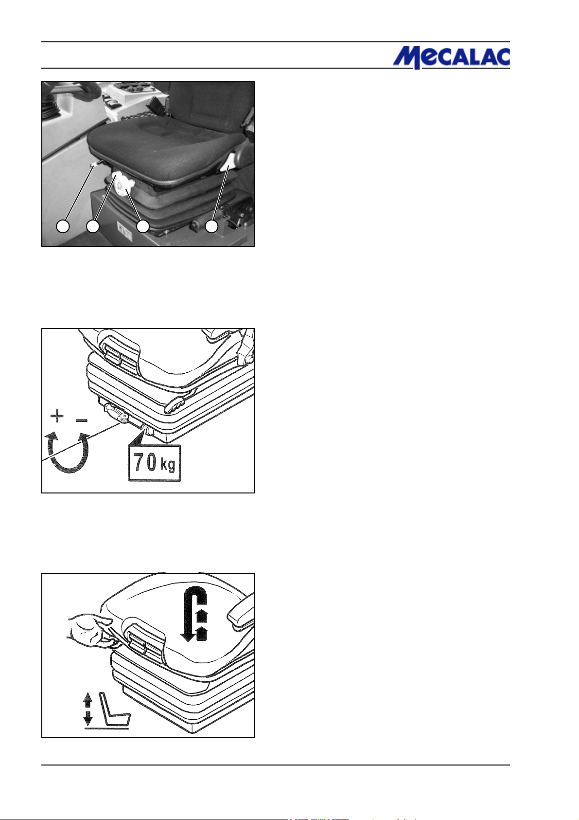
5 Operation
1 2 43
5.4 Adjusting the driver’s seat
5.4.1 Euro seat
(1) The driver’s seat can be adjusted in the horizontal
direction to suit the driver’s requirements by pulling the
handle (5-9/1) upwards and moving the seat forward or
backward.
(2) Turn the rotary knob (5-9/2) while exerting a force on
the seat to adjust the seat height.
(3) The seat suspension can be adjusted to the driver’s
weight with the hand wheel (5-9/3).
Figure 5-9
Figure 5-10
(4) Adjust or swing forward the backrest by simultaneously pulling up the hand lever (5-9/4).
5.4.2 Grammer seat
(1) Weight adjustment:
Adjust the seat to the driver’s weight by actuating the weight
adjustment lever. The set driver’s weight is visible in the
inspection window (5-10).
Figure 5-11
(2) Height adjustment:
The height can be adjusted in several steps.
Lift the driver’s seat to the desired height until it can be
heard to engage. The seat returns to the lowest position
when it is lifted over the topmost position (stop) (5-11).
P070/P071/P085/P086/P100/P1015-8
Page 51
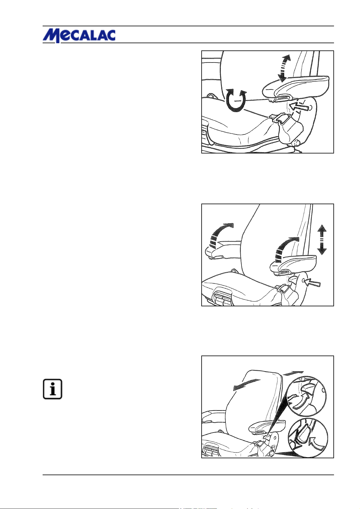
(3) Armrest inclination:
Turn the handwheel (5-12/arrow) to adjust the armrest in
longitudinal direction.
(4) Arm rests:
If desired, you can swing the armrests to the rear and adjust
their height.
Operation 5
Figure 5-12
To adjust the armrest height, remove the round cap
(5-13/arrow) in the covering.
Loosen the hex nut (wrench size 13 mm), set the armrest
as desired and tighten the nut again. Push the removed cap
onto the nut again.
(5) Adjusting the backrest:
Use the locking lever (5-14/arrow) to adjust the backrest.
NOTE
The locking lever must engage in the desired
position. It must be impossible to move the
backrest to another position when the lever has
engaged.
Figure 5-13
Figure 5-14
P070/P071/P085/P086/P100/P101 5-9
Page 52
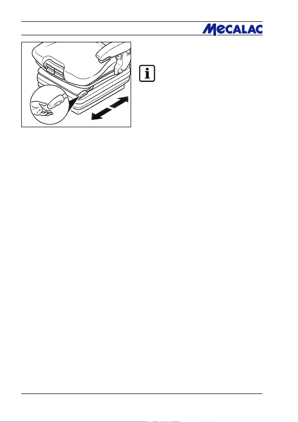
5 Operation
Figure 5-15
(6) Longitudinal adjustment:
You can adjust the seat in longitudinal direction when you
pull the lever (5-15) upwards.
NOTE
The locking lever must engage in the desired
position. It must be impossible to move the driver’s
seat to another position when the lever has
engaged.
P070/P071/P085/P086/P100/P1015-10
Page 53

Attachments
Page 54
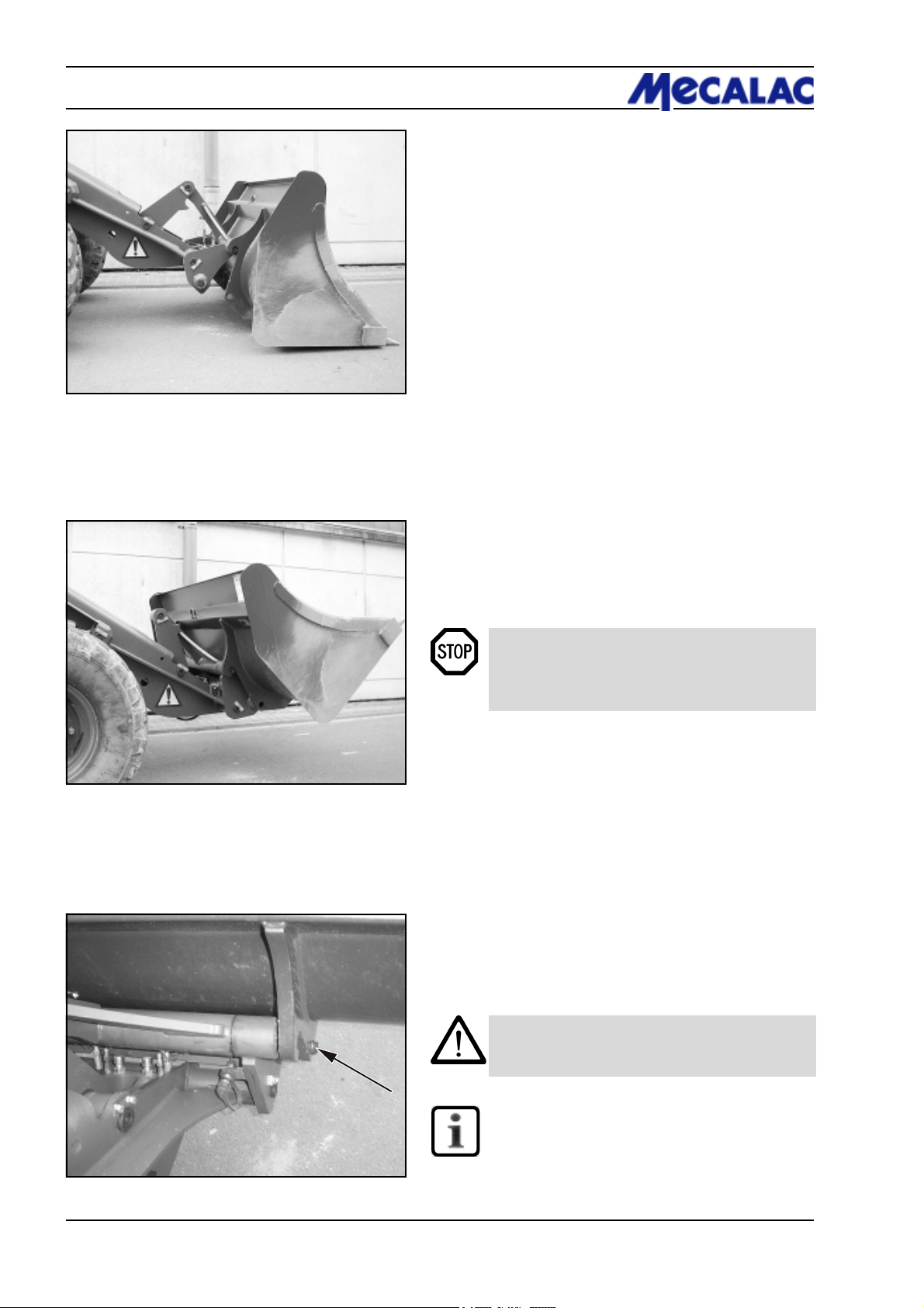
6 Attachments
6 Attachments
6.1 Mounting and dismounting attachments without hydraulic connections
6.1.1 Standard/lightweight bucket
Mounting
(1) Bring the bucket arm to its lowest position and tip the
quick-change device.
(2) Drive the loader up to the bucket (6-1).
Figure 6-1
Figure 6-2
(3) Pick up the bucket using the quick-change device
and, by simultaneously tilting the quick-change device,
raise the bucket until the quick-change device is next to it
(6-2).
(4) Lock the bucket with the pilot valve for the auxiliary
hydraulics (4-8/5).
(5) Check that the device is mounted and locked correctly
on both sides.
DANGER
The two bolts of the quick-change device must be
in the bore holes of the bucket suspension and
must be clearly visible (6-3/arrow).
Dismounting
(1) Place the bucket firmly on the ground.
Figure 6-3
(2) Press the release button for the quick-change device
(4-8/11) and unlock the bucket with the pilot valves for the
auxiliary hydraulics (4-8/5).
(3) Tilt the quick-change device and reverse out.
CAUTION
The hydraulic quick-change device must only be
locked when an attachment has been mounted.
NOTE
The type plate is on the rear of the bucket, on the
right-hand side beneath the cross arm.
P070/P071/P085/P086/P100/P1016-2
Page 55
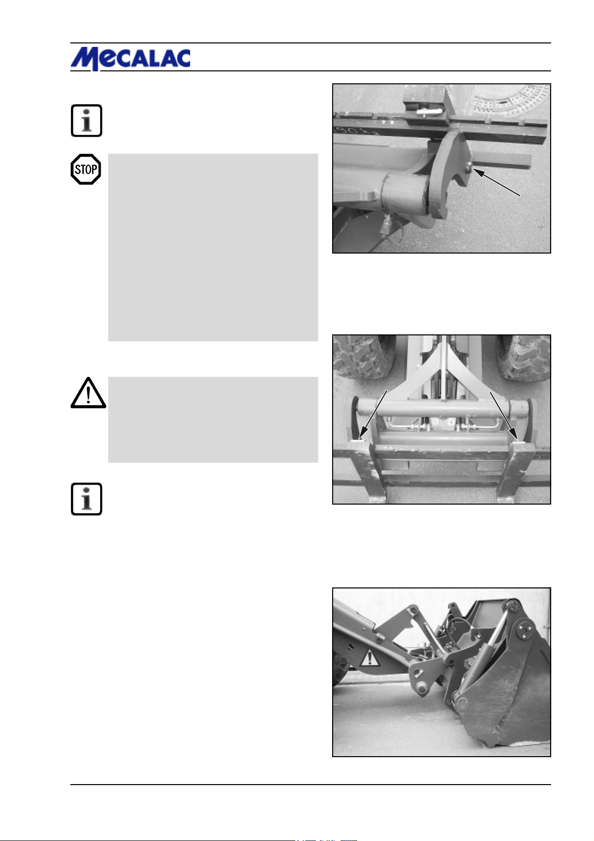
6.1.2 Fork-lift attachment
NOTE
Mounting and dismounting are carried out in the
same way as for the standard/lightweight bucket
(section 6.1.1).
DANGER
- The two bolts of the quick-change device must
be in the bore holes of the fork-lift attachment
suspension and must be clearly visible (6-4/
arrow).
- Distribute the load equally on both fork tines and
secure it against moving and falling off.
- Let the load rest against the rear of the fork and
tilt the fork-lift attachment.
- Position both fork tines at an equal distance
from the centre (6-5/arrows) and lock them.
- Moving loads with the fork-lift attachment is only
permitted close to the ground!
- Protect the fork-lift attachment against tipping
over when it has been dismounted; danger of
injuries!
Attachments 6
Figure 6-4
CAUTION
- The hydraulic quick-change device must only
be locked when an attachment has been
mounted.
- The fork tines are locked correctly when the two
tiltable locking levers fully rest on the fork
carrier.
NOTE
The type plate is on the rear of the upper fork
carrier, on the right-hand side.
6.2 Mounting and dismounting attachments with a hydraulic connection
6.2.1 Multi-purpose bucket
Mounting
(1) Bring the bucket arm to its lowest position and tip the
quick-change device.
Figure 6-5
(2) Drive the loader up to the bucket (6-6).
Figure 6-6
P070/P071/P085/P086/P100/P101 6-3
Page 56
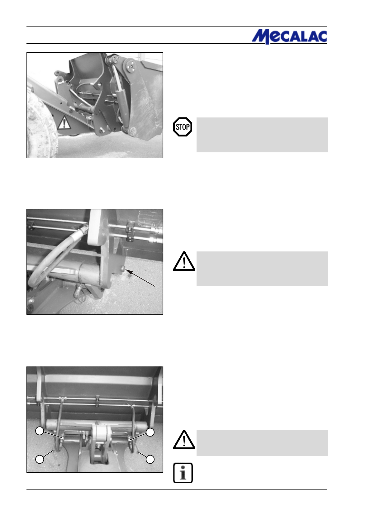
6 Attachments
(3) Pick up the bucket using the quick-change device and,
by simultaneously tilting the quick-change device, raise the
bucket until the quick-change device is next to it (6-7).
(4) Lock the bucket with the pilot valve for the auxiliary
hydraulics (4-8/5).
(5) Check that the device is mounted and locked correctly
on both sides.
DANGER
The two bolts of the quick-change device must be
in the bore holes of the bucket suspension and
must be clearly visible (6-8/arrow).
Figure 6-7
Figure 6-8
2
1 1
Figure 6-9
(6) Shut down the engine.
(7) Depressurise the hydraulic lines. For this purpose,
move the pilot valve for the auxiliary hydraulics (4-8/5) back
and forth several times.
(8) Pull off the protective caps from the hoses of the quickchange device (6-9/1).
(9) Swing up the protective flaps of the quick-change
couplings on the multi-purpose bucket (6-9/2) and connect
them with the hoses of the quick-change device (6-9) by
tightly pushing them in.
CAUTION
When making connections, make sure that the
hydraulic ports are clean and completely connected.
Dismounting
(1) Place the multi-purpose bucket firmly on the ground.
(2) Shut down the engine.
(3) Depressurise the hydraulic lines. For this purpose,
move the pilot valve for the auxiliary hydraulics (4-8/5) back
and forth several times.
(4) Disconnect the quick-change couplings on the multipurpose bucket from the hoses of the quick-change device
by pulling firmly.
(5) Fit the protective caps on the hoses of the quickchange device (6-9/1).
(6) Start the engine and unlock the bucket:
Press the release button for the quick-change device
(4-8/11) and unlock the bucket with the pilot valves for the
auxiliary hydraulics (4-8/5).
(7) Further dismounting is in the reverse order.
2
CAUTION
The hydraulic quick-change device must only be
locked when an attachment has been mounted.
NOTE
The type plate is on the rear of the bucket, on the
right-hand side beneath the cross arm.
P070/P071/P085/P086/P100/P1016-4
Page 57
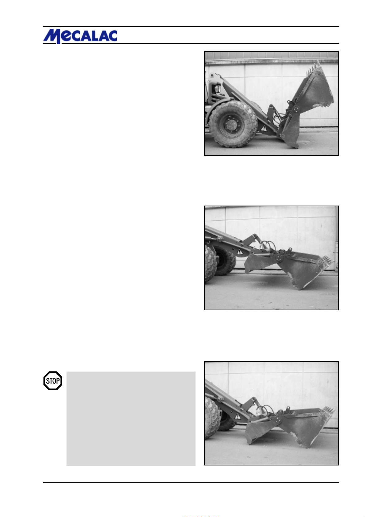
Notes on application of the multi-purpose bucket
The multi-purpose bucket can be used for:
- peeling (6-10)
Figure 6-10
- scraping (6-11)
Attachments 6
- grabbing (6-12) and
- in bucket operation.
6.3 Use of additional attachments
DANGER
1. Only those attachments described in these
operating instructions may be used.
2. We emphasise that attachments that are not
supplied by us are also not tested and approved
by us. Use of such products can under certain
conditions adversely affect the present
constructional qualities of your loader and thus
limit the active and passive driving safety. The
manufacturer cannot be held responsible for
damage that occurs through the use of such
products.
Figure 6-11
Figure 6-12
P070/P071/P085/P086/P100/P101 6-5
Page 58

Page 59

Rescue, towing,
lashing, lifting by crane
Page 60
7 Rescue, towing,
lashing, lifting by crane
7 Rescue, towing, lashing, lifting
by crane
7.1 Rescue, towing, lashing
7.1.1 Rescue/towing of the articulated
loader if the engine or drive has failed
CAUTION
The articulated loader must not be tow-started.
Any attempt to tow-start leads to damage.
DANGER
Secure the rescue location if it is on a public road.
NOTE
- Towing is only permitted to clear the site or a
street.
- Preparation for towing depends on whether the
engine has failed, thus causing a failure of the
entire hydraulic system, or if only the drive has
failed and the engine can drive the rest of the
hydraulic system.
7.1.1.1 Towing the articulated loader when
the engine has failed
(1) Actuate the toggle switch for the hazard flasher
(4-8/13).
(2) Set the drive switch (4-10/11) to “0”.
(3) Apply the parking brake (4-9/3).
CAUTION
If the rescue location is on an uphill/downhill
grade, wheel chocks must be placed on the
sloping side of both front axle wheels in addition
to applying the parking brake.
NOTE
The preparations described in steps (4) and (5)
are only to be carried out if the rescue location
is not on a public road:
(4) Cover the bucket cutting edge and teeth with the
bucket protector (5-4/arrow).
(5) Insert the plug of the bucket protector into the socket
(5-5/arrow, option).
(6) Push the valve lever for the working hydraulics
(4-8/4) beyond its pressure point into the forward position
(float position).
P070/P071/P085/P086/P100/P1017-2
Page 61
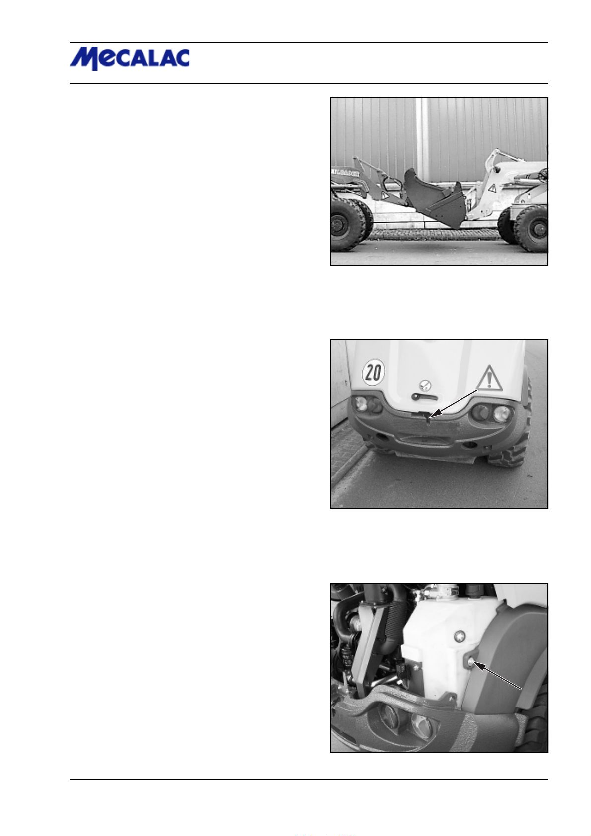
(7) Using a suitable lifting device, e.g. a second loader
with an attached bucket, lift the bucket arm of the loader to
be towed until the mechanical bucket arm support can be
inserted at the loader to be towed (7-1).
(8) Mechanically prop up bucket arm [e.g. by inserting
the bucket arm support (option) (1-2/arrow)] and lower
bucket arm until it rests on the bucket arm support.
(9) Disable the float position by pulling the pilot valve for
the working hydraulics to the rear beyond its pressure
point.
(10) Lock the pilot valves for working and auxiliary hydraulics (1-2/arrow) (rear position).
Rescue, towing, 7
lashing, lifting by crane
Figure 7-1
(11) Connect the tow rod to the loader to be towed
(7-2/arrow) and to the towing vehicle.
(12) Undo the fastening screw on the hydraulic oil tank
(7-3/arrow) of the right rear mudguard.
Figure 7-2
Figure 7-3
P070/P071/P085/P086/P100/P101 7-3
Page 62
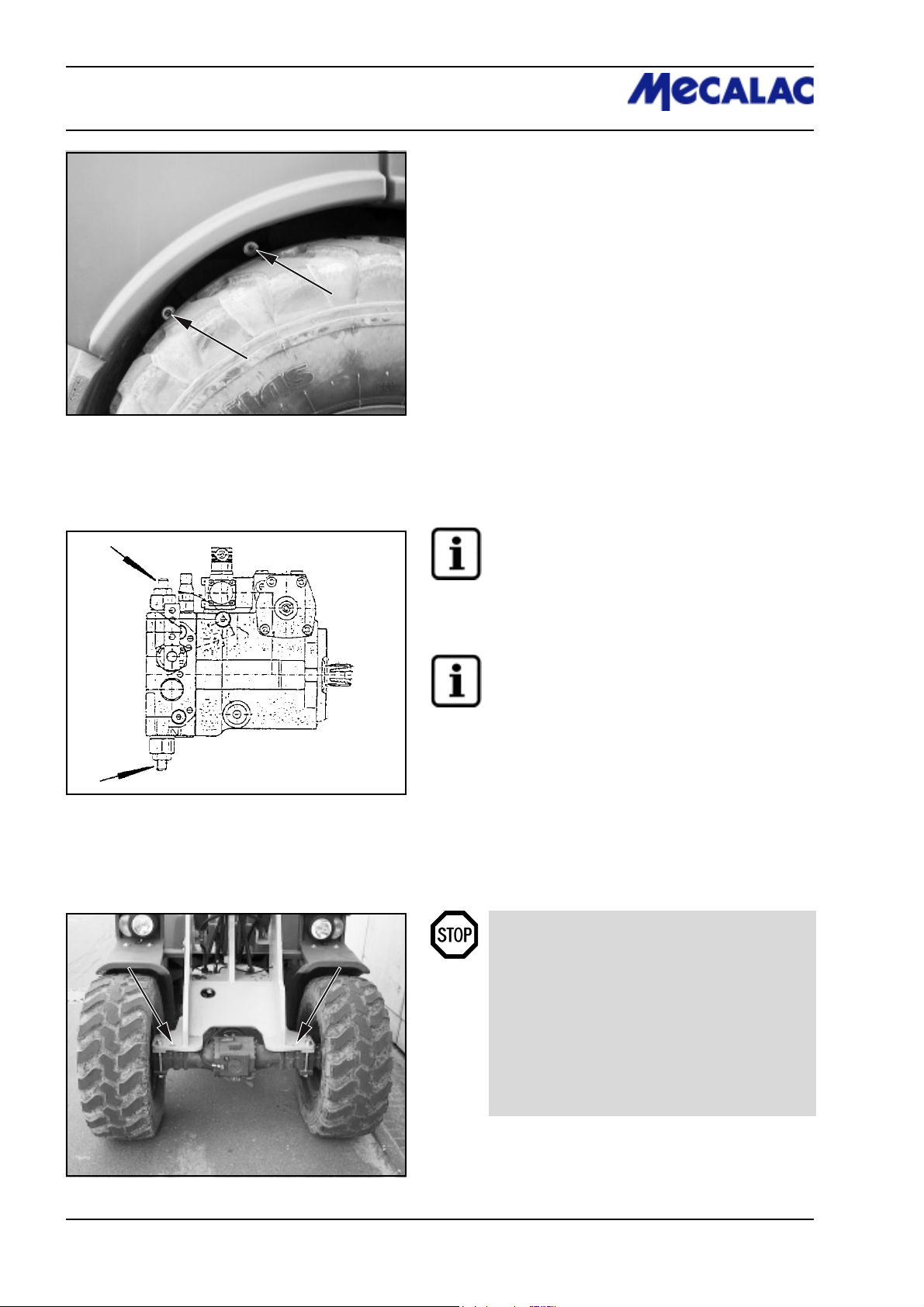
7 Rescue, towing,
lashing, lifting by crane
(13) Undo fastening screws in the wheel house rear right
(7-4/arrows) and pull the mudguard off to the side.
Figure 7-4
Figure 7-5
(14) Switch the hydrostatic drive motor to free oil flow
before towing. For this purpose, screw in the setscrews at
both high pressure relief valves (7-5/arrows) of the drive
pump until they are level with the hexagon nuts (size 13)
loosened beforehand. Then tighten the hexagon nuts.
NOTE
The operator of the loader is responsible that the
(optional) tool required to remove the mudguard
(items 12 and 13) and to adjust the drive pump
(item 14) is always on board the loader.
NOTE
After towing has been completed, loosen the
hexagon nuts again. Screw the setscrews out of
both high-pressure relief valves until they stop
and tighten the lock nuts.
(15) Remove the chocks (if applicable).
(16) Release the parking brake lever (4-9/3).
Figure 7-6
DANGER
- More power is required to steer if the engine
has failed.
- Tow the loader at walking speed (2 km/h).
- The towing distance should not exceed 1 km.
- For a longer distance, the defective loader must
be loaded onto a truck (for the lashing points,
see 7-2/arrow, 7-7/6/arrows and 7-7/arrows).
P070/P071/P085/P086/P100/P1017-4
Page 63
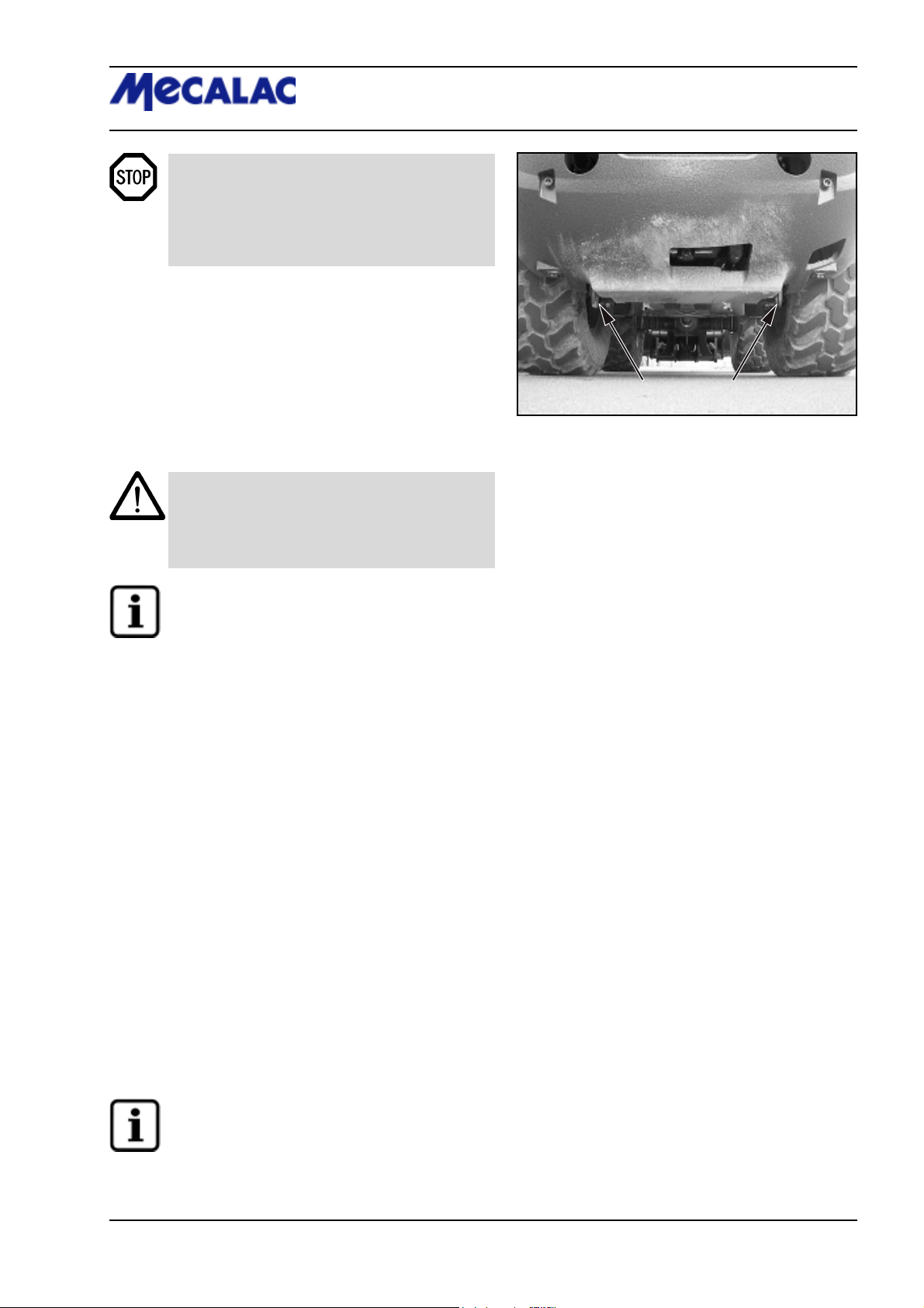
- The max. permissible load of the shunting and
towing coupling (7-2/2) is 4.5 t horizontally in
the longitudinal direction.
- The max. permissible load of the lashing/loadbearing points (7-6/arrows, and 7-7/arrows) is
2.0 t.
7.1.1.2 Towing the articulated loader when
the traction drive has failed
(1) Actuate the toggle switch for the hazard flasher (4-8/13).
(2) Set the drive switch (4-10/11) to “0”.
(3) Apply the parking brake (4-9/3).
CAUTION
If the rescue location is on an uphill/downhill grade,
wheel chocks must be placed on the sloping side of
both front axle wheels in addition to applying the
parking brake.
Rescue, towing, 7
lashing, lifting by crane
Figure 7-7
NOTE
The preparations described in steps (4) and (5)
are only to be carried out if the rescue location
is not on a public road:
(4) Cover the bucket cutting edge and teeth with the
bucket protector (5-4/arrow).
(5) Insert the plug of the bucket protector into the socket
(5-5/arrow, option).
(6) Lift and mechanically prop up bucket arm [e.g. by
inserting the bucket arm support (option) (1-2/arrow)] and
lower bucket arm until it rests on the bucket arm support by
actuating the lever for the working hydraulics (4-8/4).
(7) Lock the pilot valves for working and auxiliary hydraulics (1-2/arrow) (rear position).
(8) Connect the tow rod to the loader to be towed (7-2/
arrow) and to the towing vehicle.
(9) Undo the fastening screw on the hydraulic oil tank
(7-3/arrow) of the right rear mudguard.
(10) Undo fastening screws in the wheel house rear right
(7-4/arrows) and pull the mudguard off to the side.
(11) Switch the hydrostatic drive motor to free oil flow
before towing. For this purpose, screw in the setscrews at
both high pressure relief valves (7-5/arrows) of the drive
pump until they are level with the hexagon nuts (size 13)
loosened beforehand. Then tighten the hexagon nuts.
NOTE
The operator of the loader is responsible that the
(optional) tool required to remove the mudguard
(items 9 and 10) and to adjust the drive pump
(item 11) is always on board the loader.
P070/P071/P085/P086/P100/P101 7-5
Page 64
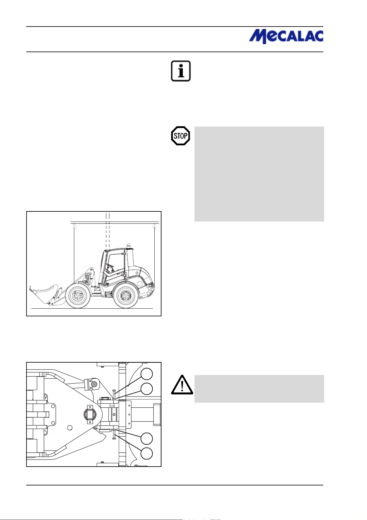
7 Rescue, towing,
lashing, lifting by crane
A
A
2
C
1
C
2
1
B
D
NOTE
After towing has been completed, loosen the
hexagon nuts again. Screw the setscrews out of
both high-pressure relief valves until they stop
and tighten the lock nuts.
(12) Remove the chocks (if applicable).
(13) Release the parking brake (4-9/3).
DANGER
- With the engine running, tow the loader at
walking speed (2 km/h).
- The towing distance should not exceed 1 km.
- For a longer distance, the defective loader must
be loaded onto a truck (for the lashing points,
see 7-2/arrow, 7-7/6/arrows and 7-7/arrows).
- The max. permissible load of the shunting and
towing coupling (7-2/2) is 4.5 t horizontally in
the longitudinal direction.
- The max. permissible load of the lashing/loadbearing points (7-6/arrows, and 7-7/arrows) is
2.0 t.
D
Figure 7-8
7.2 Lifting by crane
The loader to be lifted must be prepared as follows:
(1) Set the drive switch (4-10/11) to “0”.
(2) Set hydraulic drive stage „I“ (4-10/9).
(3) Apply the parking brake (4-9/3).
(4)
Lift or lower the bucket arm until the lowest point of the bucket
arm or of the bucket is at least 30 cm above the road (5-4).
(5) Close the pilot valve for the working and auxiliary
hydraulics (1-2/arrow).
(6) Insert the articulation safeguard into the articulation
joint (1-3/arrow).
2
CAUTION
1
(7) Engage the float safeguard. To do so, loosen lock nuts
(7-9/1) on the left and right of the loader, screw in securing
screws (7-9/2) all the way to the stop and tighten lock nuts
again.
Do not operate the steering while the articulation
safeguard is in place.
1
(8) Lock both doors.
2
(9) Fold the outside mirror inwards.
Figure 7-9
P070/P071/P085/P086/P100/P1017-6
Page 65
CAUTION
The following items must be observed when
lifting the loader by crane (Figure 7-8):
- The lifting point (A1 - loader without standard
bucket or A2 - loader with standard bucket) of the
lifting device (B) must be precisely vertically over
the centre of gravity (C1 or C2) of the loader so that
the lifting device is horizontally above the longitudinal centre axis of the loader.
- The lifting gear (D) must lead vertically upwards
from the lifting points of the loader (7-6/arrows
and 7-7/arrows).
DANGER
The lifting gear must have a lifting capacity of at
least 3.0 t.
NOTE
Disengage the float safeguard after successful
loading with a crane. To do so, loosen lock nuts
(7-9/1) on the left and right of the loader, screw
out securing screws (7-9/2) all the way to the stop
and tighten lock nuts again.
Rescue, towing, 7
lashing, lifting by crane
P070/P071/P085/P086/P100/P101 7-7
Page 66

Page 67

Maintenance
Page 68
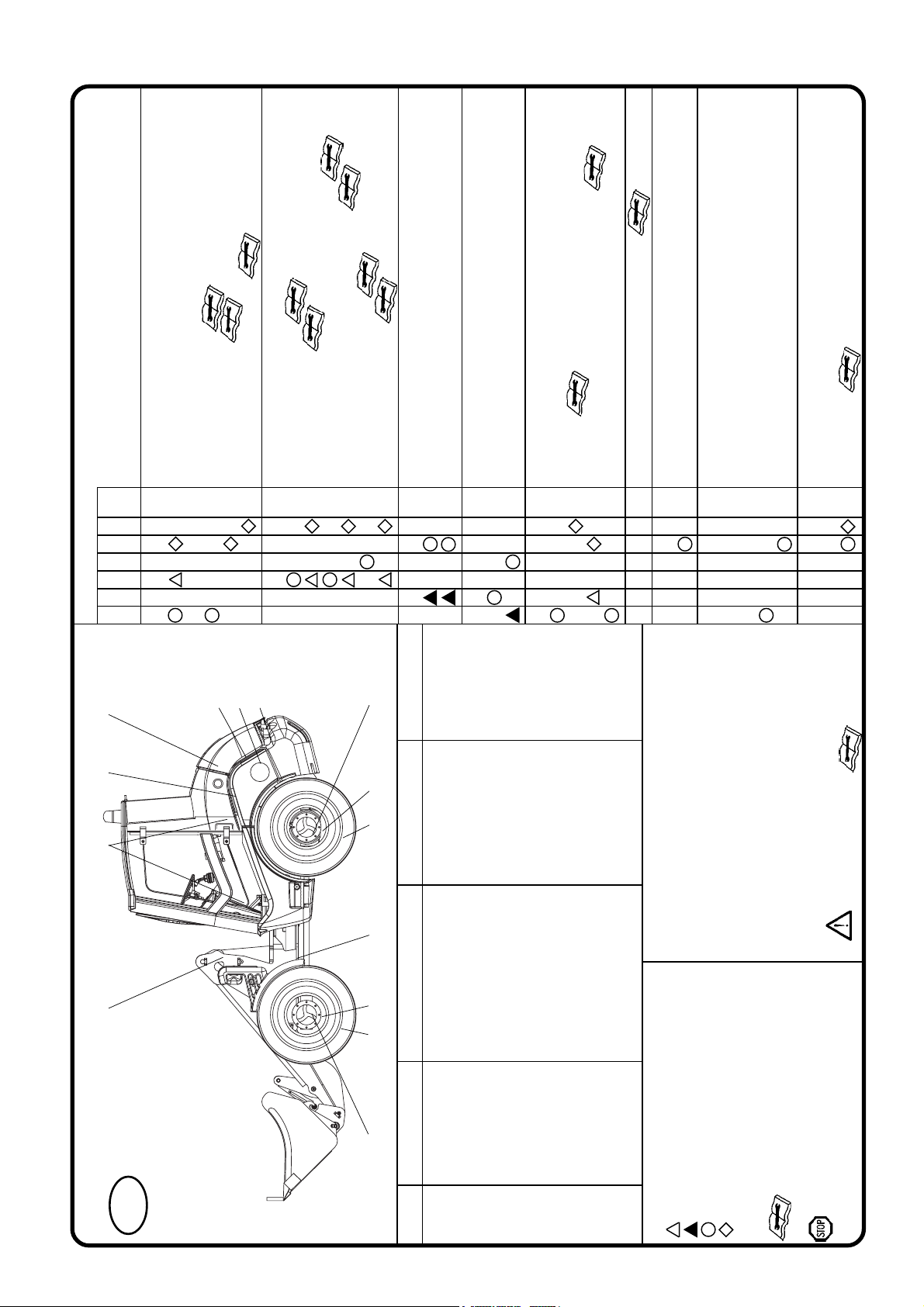
max. permissible intervals or
shorter (depending on use)
Check filter element
Replace filter element
Maintenance points
Pos.
1.1 Maintenance acc. to manufacturer
1.2 Dry air filter system
1 Engine
1500
500
200
100
50
10
Every x operating hours
Replace safety cartridge (option)
1.1/1.2/1.3
5.1/5.2/5.3
2 Axles / distribution gear
2.1 Front axle oil level check
2.2 Change front axle oil
2.3 Check oil level in rear axle with distribution gear
2.4 Change oil in rear axle with distribution gear
2.5 Planetary gear oil level check
2.6 Change planetary gear oil
3 Axles / cardan shaft / articulated pendulum joint
3.1 Check fastening of axles (710 Nm)
7.1
starting work
3.2 Check fastening of cardan shaft (35 Nm)
4 Wheels and tyres
4.1 Check air pressure
4.2 Check fastening of wheel nuts (440 Nm)
5 Hydraulic system
5.1 Oil level check (view glass)
5.2 Oil change
5.3 Replace filter inserts, observe electr. indicator
5.4 Check and clean hydraulic oil cooler
6 Grease points (indicated in red)
7 Battery
7.1 Visual inspection
8 Brake systems
8.1 Service/parking brake: Function and visual check before
8.2 Service/parking brake: Visually check compensation tank
8.3 Service/parking brake: Check brake lining, adjust if necessary
9 Lighting system / fresh air filter
9.1 Function test before starting work
9.2 Fresh air filter
20
9.1 8.2/8.3 9.2 5.4
GB
23110576
8 Maintenance schedule
with LS additive
1 Motor oil ACEA E7, E5, E3; API CI-4 acc. to manufacturer ca. 8.5 l with oil filter
2.2 Transmission oil MIL-L-2105 B = API-GL5-6-LS SAE 85 W 90-LS approx. 4.2 l
Item Designation Specification Viscosity Filling amount
*
2.1/2.2/2.5/2.6/3.1/8.1/8.2 4.1 4.2 3.2 4.1 4.2 2.3/2.4/2.5/2.6/3.1
*
with LS additive
2.6 Transmission oil MIL-L-2105 B = API-GL5-6 SAE 85 W 90 ca. 2 x 0.85 l each
2.4 Transmission oil MIL-L-2105 B = API-GL5-6-LS SAE 85 W 90-LS approx. 4.85 l
*
5.2 Hydraulic oil DIN 51524 - HVLP 46 ISO VG 46, VI > 180 approx. 60 l
***
7 Distilled water as required
6 Grease DIN 51825 - KPF 1/2 N-20 as required
Operate the service brake
with mineral oil only!
CAUTION !
Grease points (indicated in red)
1. Lubricate bolts every 10 operating hours with grease (DIN
51825 - KPF 1/2 N-20).
2. Lubricate glide points as required and always after cleaning
using grease DIN 51825 - KPF 1/2 N-20.
Oil lubrication points
3. Use MIL-L-2104 C engine oil to lubricate the joints and
deflection levers every 50 operating hours.
Optional equipment: Biodegradable hydraulic oil
4. Ester-based synthetic hydraulic oil
viscosity class ISO VG 46 VI > 180
Eliminate any faults
found
}
8 Mineral oil DIN 51524 - HVLP 46 ISO VG 46, VI > 180 as required
Key to symbols
First oil change, first filter replacement
First check
Check
Change
Refer to operating instructions
The markings, filling and inspection plugs
are binding
*
Caution
When carrying out maintenance work, heed
accident prevention regulations!
8-1 P070/P071/P085/P086/P100/P101
Page 69

8 Maintenance
8.1 Notes regarding maintenance
DANGER
- The engine must be turned off.
- For work to be carried out under the bucket
arm:
- the bucket must be emptied or the attachment
must be relieved,
- the bucket arm must be mechanically propped
up [e.g. by inserting the bucket arm support
(option) (1-1/arrow)],
- lock (4-8-/6) pilot valves for the working and
auxiliary hydraulics (4-8/4 and 4-8/5).
- For work to be carried out in the area of the
articulation joint, the articulation safeguard must
be inserted (1-3/arrow).
- Do not operate the steering while the
articulation safeguard is in place.
- The loader must be secured against rolling by
applying the parking brake (4-9/3) and by setting
the drive direction switch (4-10/11) to position „0“.
In addition, wedges (8-1/2) must be placed on
both sides of one of the two wheels of the front axle.
Maintenance 8
1
CAUTION
- Change the oil when the units are lukewarm.
- Check the oil level when the loader is on level
ground and when the bucket arm is in its lowest
position.
- Replace damaged filter inserts and gaskets
immediately.
- Clean pressure lubrication fittings before lubricating.
NOTE
- For the maintenance work required, refer to the
maintenance plan (page 8-1).
- Damage which is traceable to non-observance
of the maintenance plan is not covered by the
warranty.
- The lubricants listed in the maintenance plan can
be used at ambient temperatures ranging from
-15°C to +40°C.
- The compensation tank for coolant is located
beneath the maintenance flap at the right of the
loader (8-1/1).
2
Figure 8-1
CAUTION
For ambient temperatures below 15° C, refer to
the description in chapter 5.2.2 “Winter operation”.
P0700/P0710/P0850/P0860/P1000/P1010 8-3
Page 70
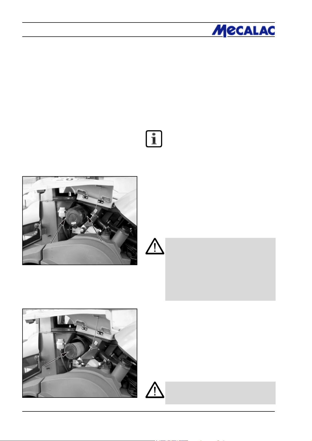
8 Maintenance
8.2 Maintenance work
8.2.1 Oil level check, engine
See the operating instructions for the engine.
8.2.2 Oil change, engine
See the operating instructions for the engine.
8.2.3 Maintaining/replacing the air filter
NOTE
- Maintenance (visual inspection) of the filter
cartridge must be carried out every 10 ope-
rating hours. According to the operating conditions, shorter intervals may apply.
- Clean the filter cartridge if necessary.
- Replace the filter cartridge every 500 ope-
rating hours.
Figure 8-2
(1) Open the engine hood, then the maintenance flap on
the loader’s left side.
(2) Loosen the three retaining clamps of the air filter lid
(8-2/arrows) and remove the air filter lid.
(3) Pull out the filter cartridge (8-3/arrow) by carefully
turning it back and forth.
(4) Clean the filter cartridge.
CAUTION
- For cleaning, use a compressed air gun to
which a pipe (angled at 90°) has been attached.
The pipe must be sufficiently long to reach the
bottom of the cartridge. Use dry compressed
air of no more than 5 bar to blow out the
cartridge by moving the pipe back and forth in
the interior of the cartridge. Cleaning can be
stopped when dust formation ceases.
- Do not use petrol or hot liquids for cleaning.
(5) Use a hand-held lamp to check the cartridge paper
and the rubber gasket of the filter cartridge for damage.
If the cartridge or the gasket is damaged, replace the
cartridge.
Figure 8-3
(6) Carefully insert the filter cartridge.
(7) Install the air filter lid on the filter housing in such a way
that the direction arrow in the marking "OBEN-TOP“ points
upwards. This ensures that the umbrella valve faces
downwards.
CAUTION
Check all connection pipes and hoses of the air filter
system for damage before starting the engine.
P0700/P0710/P0850/P0860/P1000/P10108-4
Page 71
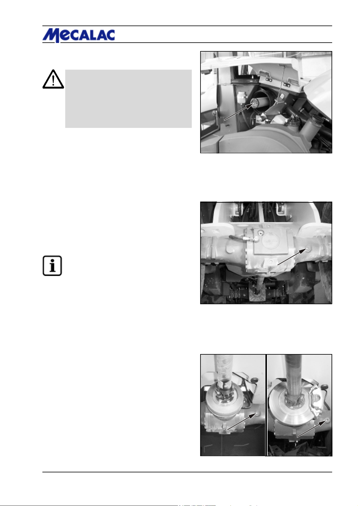
8.2.4 Replacing the safety cartridge
(option)
CAUTION
- The safety cartridge must not be cleaned.
- The safety cartridge must be replaced after the
filter cartridge has been maintained/cleaned
3 times, but at the latest after two years.
- Make sure that no dirt or dust can enter the filter
housing during replacement of the safety
cartridge.
(1) Remove the filter cartridge (section 8.2.3).
Maintenance 8
(2) Pull out the safety cartridge (8-4/arrow) by carefully
turning it back and forth and replace the safety cartridge
and the filter cartridge with new cartridges.
(3) The remaining assembly is performed as described in
section 8.2.3 (6) and (7).
8.2.5 Oil level check, front axle
(1) Unscrew the plugs from the axle arch (8-5/arrow or
8-6/arrow).
NOTE
- The oil level must reach the plug bore.
- Collect any oil that escapes.
(2) Screw in the plug again.
Figure 8-4
Figure 8-5
AX 700/20 km/h
AX 850/20 km/h
Figure 8-6
AX 700/30 km/h
AX 850/30 km/h
AX 1000
P0700/P0710/P0850/P0860/P1000/P1010 8-5
Page 72
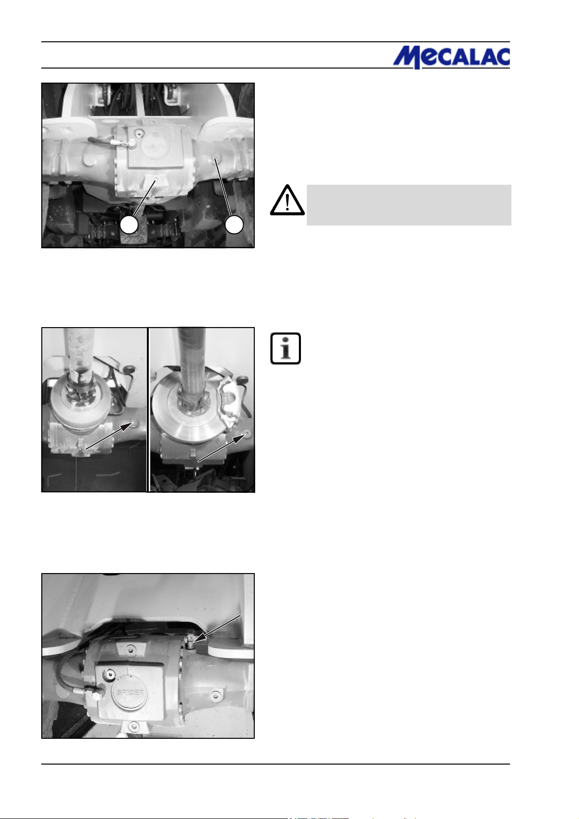
8 Maintenance
1 2
8.2.6 Oil change , front axle
(1) Place a sufficiently large oil drain pan underneath.
(2) Unscrew the plugs from the axle arch (8-7/1, 8-7/2 and
8-8/arrow) and drain the oil.
CAUTION
Waste oil must be disposed of in such a way that it
will not cause pollution!
Figure 8-7
AX 700/20 km/h
AX 850/20 km/h
Figure 8-8
AX 700/30 km/h
AX 850/30 km/h
AX 1000
(3) Screw in the plug (8-7/1) again.
(4) Fill in oil via the plug bore (8-7/2 or 8-8/arrow) until the
oil level reaches the opening.
NOTE
- The vent valve of the axle (8-9/arrow) must be
free from dirt.
- Details regarding the amount of oil required are
given in the maintenance plan (page 8-1).
- After a few minutes, when the oil level has
lowered, top up the oil until the oil reaches the
marked level and remains stable.
(5) Screw the plugs (8-7/2 and 8-8/arrow) back in.
Figure 8-9
P0700/P0710/P0850/P0860/P1000/P10108-6
Page 73
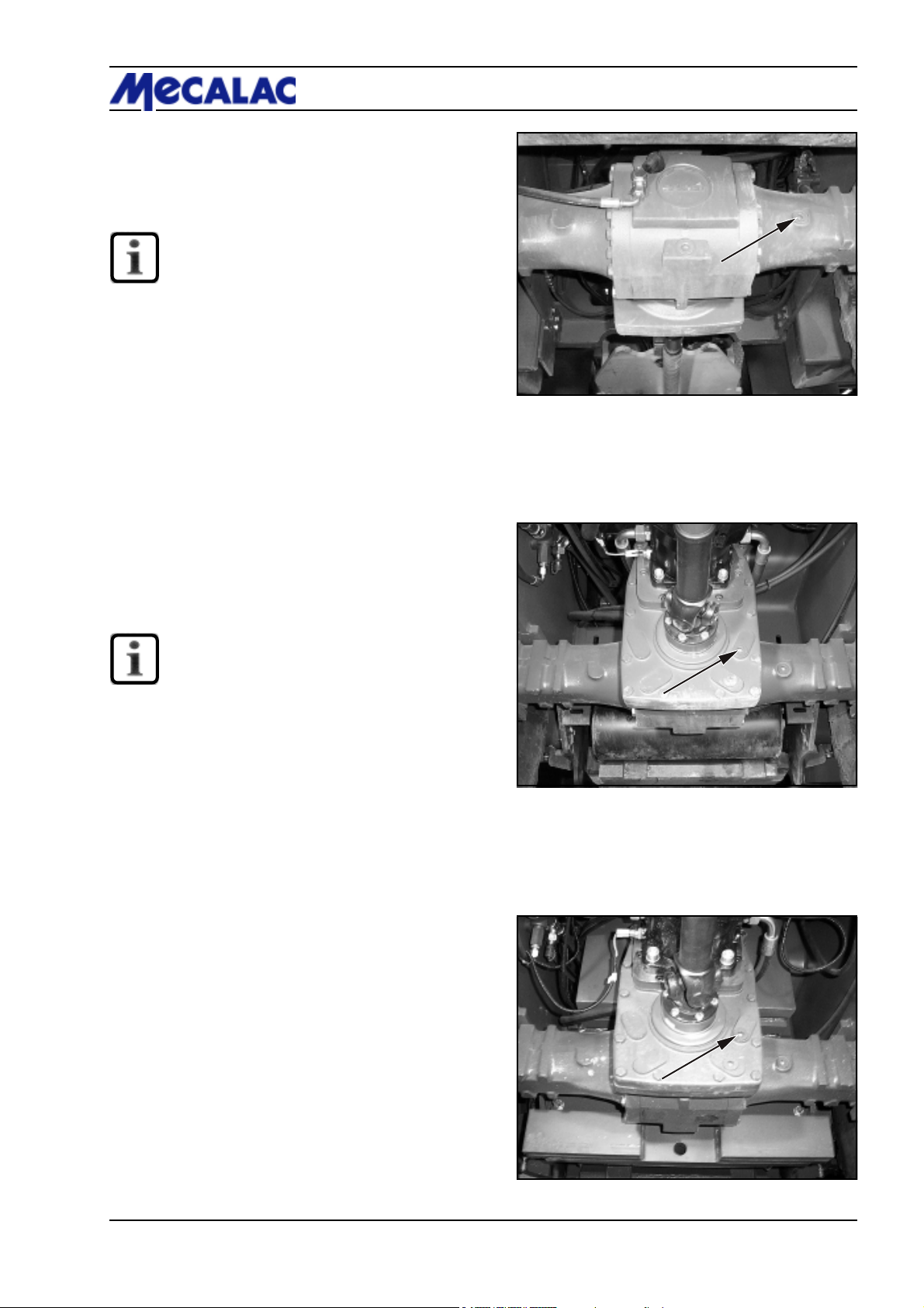
8.2.7 Oil level check , rear axle
(1) Unscrew the plug from the axle arch (8-10/arrow).
NOTE
- The oil level must reach the plug bore.
- Collect any oil that escapes.
(2) Screw in the plug again.
Maintenance 8
Figure 8-10
(3) Unscrew the plug screw from the ancillary gear
[AX 700/20 km/h and AX 850/20 km/h (8-11/arrow)] or
distribution gear [AX 700/30 km/h, AX 850/30 km/h and
AX 1000 (8-12/arrow)].
NOTE
- The axle arch and the ancillary/distribution
gear do not have a common oil filling.
- The oil level must reach the plug bore.
- Collect any oil that escapes.
(4) Screw in the plug again.
AX 700/20 km/h, AX 850/20 km/h
Figure 8-11
AX 700/30 km/h, AX 850/30 km/h, AX 1000
Figure 8-12
P0700/P0710/P0850/P0860/P1000/P1010 8-7
Page 74
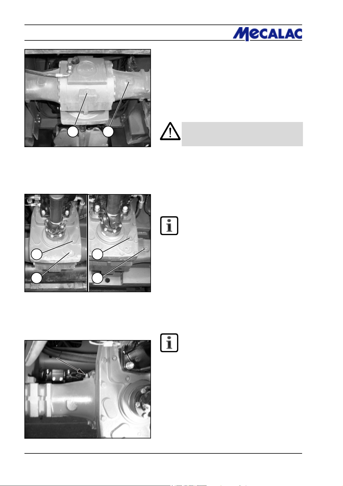
8 Maintenance
8.2.8 Oil change , rear axle
(1) Place a sufficiently large oil drain pan underneath.
(2) Unscrew screw plug from the axle arch (8-13/1 and
8-13/2) and ancillary gear [AX 700/20 km/h and
AX 850/20 km/h (8-14/1 and 8-14/2)] or distribution gear
[AX 700/30 km/h, AX 850/30 km/h and AX 1000 (8-14/3
and 8-14/4)] and drain the oil.
Figure 8-13
AX 700/20 km/h
AX 850/20 km/h
1
2
Figure 8-14
1 2
AX 700/30 km/h
AX 850/30 km/h
AX 1000
3
4
CAUTION
Waste oil must be disposed of in such a way that
it will not cause pollution!
(3) Screw in the plugs for the axle arch (8-14/1) and the
ancillary (8-14/2) or distribution gear (8-14/4) again.
(4) Fill oil into the plug bore of the ancillary (8-14/1) or
distribution gear (8-14/3) until the oil level reaches the
opening.
NOTE
- The axle arch and the ancillary/distribution
gear do not have a common oil filling.
- Details regarding the amount of oil required are
given in the maintenance plan (page 8-1).
- After a few minutes, when the oil level has
lowered, top up the oil until the oil reaches the
marked level and remains stable.
(5) Screw in the plug of the ancillary (8-14/1) or distribution gear (8-14/3) again.
Figure 8-15
(6) Fill oil into the plug bore of the axle arch (8-13/2) until
the oil level reaches the opening.
NOTE
- Details regarding the amount of oil required are
given in the maintenance plan (page 8-1).
- After a few minutes, when the oil level has
lowered, top up the oil until the oil reaches the
marked level and remains stable.
- The vent valve of the axle (8-15/arrow) must be
free from dirt.
(7) Screw in the plug of the axle arch (8-13/2) again.
P0700/P0710/P0850/P0860/P1000/P10108-8
Page 75
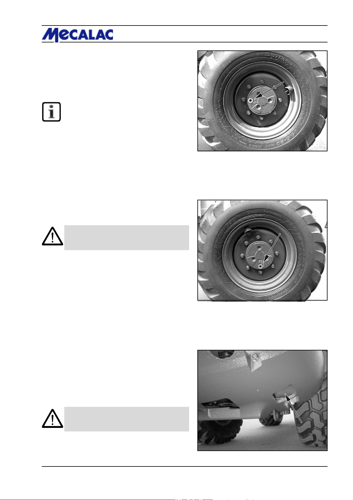
8.2.9 Oil level check , planetary gear
(1) Move the loader until the marking line ”OIL LEVEL” is
horizontal and the plug is located above the top left of the
marking line (8-16/arrow).
(2) Unscrew the plug.
NOTE
- The oil level must reach the plug bore.
- Collect any oil that escapes.
(3) Fit a new gasket and screw the plug back in.
8.2.10 Oil change, planetary gear
(1) Move the loader so that the plug (8-17/arrow) is
positioned at 6 o’clock.
(2) Place an oil drain vessel with a drain channel underneath the gear.
Maintenance 8
Figure 8-16
(3) Unscrew the drain plug and let the oil drain out.
CAUTION
Waste oil must be disposed of in such a way that
it will not cause pollution!
(4) Move the loader until the marking line ”OIL LEVEL” is
horizontal and the plug is located above the top left of the
marking line (8-16/arrow).
(5) Fill in oil via the plug bore until the oil level reaches the
opening.
(6) Use a new gasket when screwing the plug back in.
8.2.11 Oil change, hydraulic system
(1) Open the motor hood.
(2) Place an oil drain vessel (at least 70 l) to the right below
the counter weight.
(3) Unscrew the oil drain plug (8-18/arrow).
Figure 8-17
(4) Drain the oil into the oil vessel.
CAUTION
Waste oil must be disposed of in such a way that
it will not cause pollution!
(5) Screw in the oil drain plug again.
(6) Change the hydraulic oil filter cartridge (section
8.2.12).
Figure 8-18
P0700/P0710/P0850/P0860/P1000/P1010 8-9
Page 76
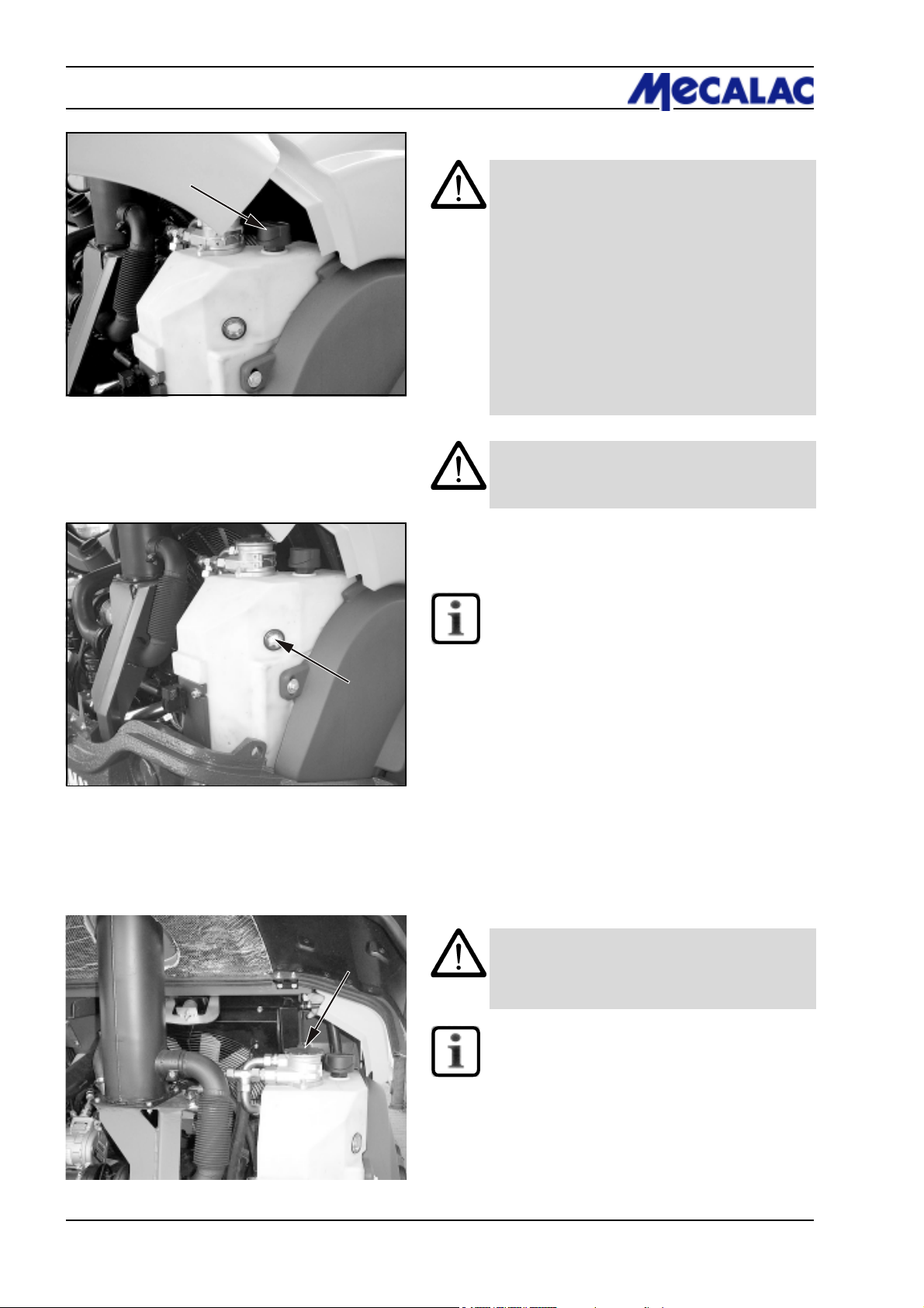
8 Maintenance
Figure 8-19
(7) Fill oil into the filler neck (8-19/arrow).
CAUTION
For those loaders which are fitted to run with
biodegradable hydraulic oil (ester-based synthetic hydraulic oil of viscosity class ISO VG 46
VI > 180) - (designation can be found on the
hydraulic oil reservoir and on the dashboard),
only this type of oil may be used for oil changes.
Mineral and biodegradable hydraulic oils must
never be mixed!
Biodegradable hydraulic oil must be changed
every 1000 operating hours.
Changing the oil type from mineral oil to biodegradable oil must be performed according to the
VDMA 24 569 conversion guidelines.
CAUTION
The service brake must be operated with mineral
oil only!
Figure 8-20
(8) Check the oil level at the sight glass (8-20/arrow).
NOTE
The oil level must be visible in the upper quarter
of the sight glass (8-7/arrow). If necessary, fill oil
into the filler neck (8-19/arrow).
(9) Close the filling nozzle.
8.2.12
Changing the hydraulic oil filter cartridge
CAUTION
Replace the filter cartridge according to the
maintenance plan or when the (optional) clogging
indicator lamp (4-9/13) lights up.
Figure 8-21
NOTE
The clogging indicator may light up prematurely
after a cold start. It will go out when the hydraulic
oil warms up.
(1) Open the motor hood.
(2) Unscrew the lid of the hydraulic oil filter (8-21/arrow
or 8-22/1).
P0700/P0710/P0850/P0860/P1000/P10108-10
Page 77
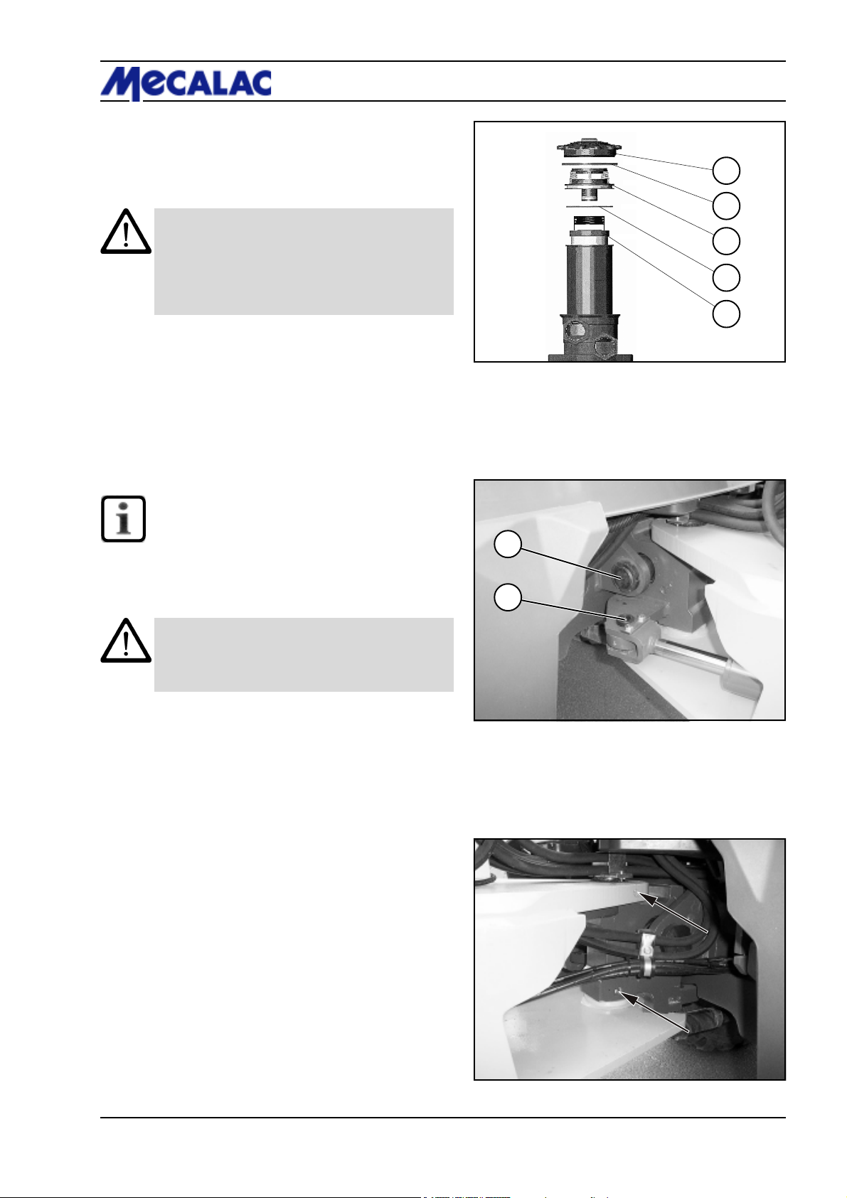
(3) Swing up pull tabs on the separator disc (8-22/3) and
lift out the separator disc.
Maintenance 8
(4) Slowly pull out the filter cartridge (8-22/5) and replace
it with a new one.
CAUTION
- Collect any hydraulic oil that drains or drips off when
you lift out the separator disc and the filter cartridge.
- The used hydraulic oil filter cartridge and the Orings must be disposed of in an environmentally
compatible manner.
(5) Fit the separator disc with a new O-ring (8-22/4).
(6) Screw on the hydraulic filter lid with a new O-ring
(8-22/2).
8.2.13 Grease points
NOTE
The grease points are marked in red on the
loader.
1
2
3
4
5
Figure 8-22
1
8.2.13.1 Articulated pendulum joint/steering
cylinder
CAUTION
Grease the pendulum bolt, the bearings of
articulation bolt and steering cylinder every 50
operating hours.
Figure 8-23/1 Pendulum bolt
Figure 8-23/2 Steering cylinder, rear
Figure 8-24/arrows Articulation bolt
2
Figure 8-23
Figure 8-24
P0700/P0710/P0850/P0860/P1000/P1010 8-11
Page 78
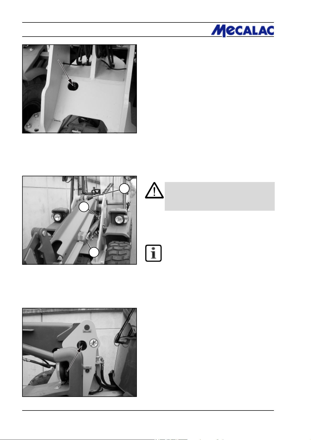
8 Maintenance
Figure 8-25
Figure 8-25/arrow Steering cylinder, front
8.2.13.2 Bucket assembly
Figure 8-26
1
2
8-26/1 Bucket assembly/front end
8-26/2 Front end/lift cylinder
8-26/3 Bucket assembly/lift cylinder
CAUTION
The bearing bolts/grease nipples of the bucket
assembly (8-26 through 8-30) must be greased
every 10 operating hours.
NOTE
3
8-27/arrow Front end/tip cylinder
Grease the bearing points on both sides of the
loader.
Figure 8-27
P0700/P0710/P0850/P0860/P1000/P10108-12
Page 79
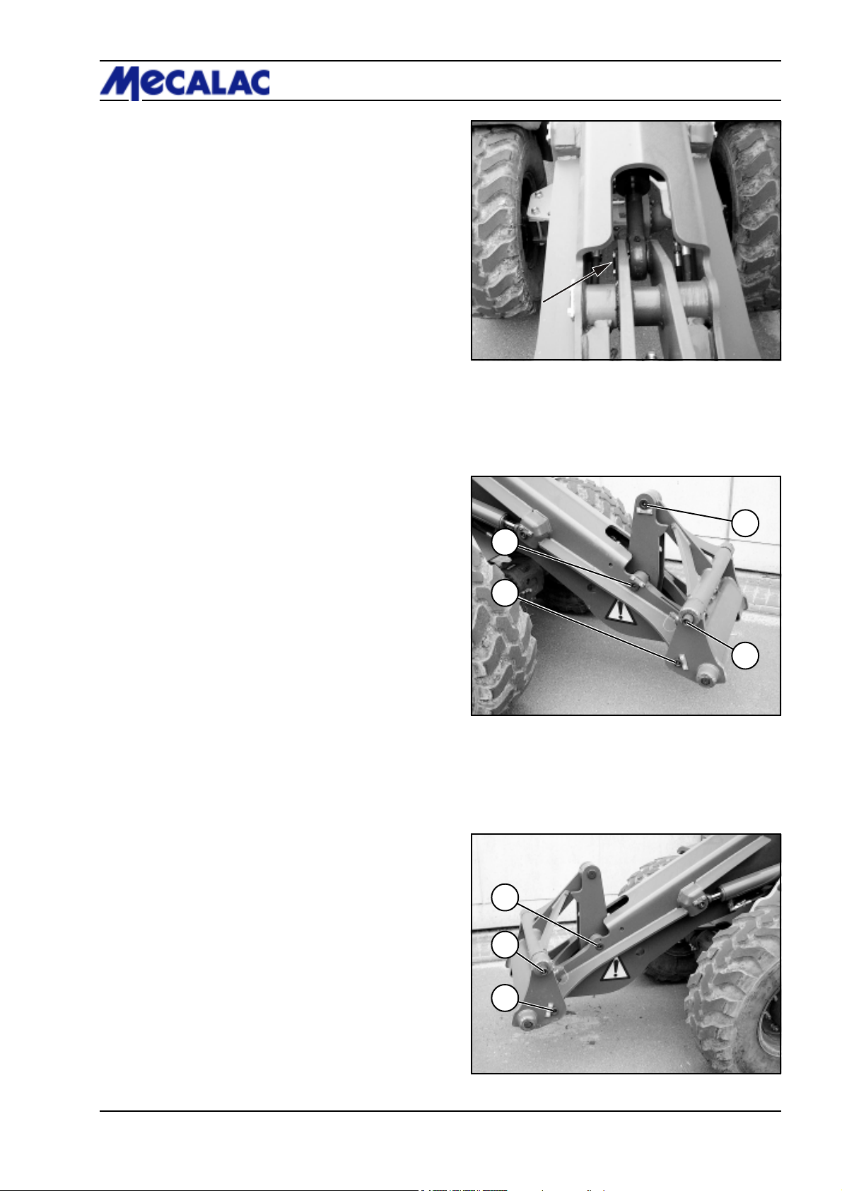
8-28/arrow Tip cylinder/deflection lever
8-29/1 Bucket assembly/deflection lever
8-29/2 Quick-change device
8-29/3 Quick-change device/pivot arm
8-29/4 Deflection lever/pivot arm
Maintenance 8
Figure 8-28
4
1
8-30/1 Bucket assembly/deflection lever
8-30/2 Quick-change device/pivot arm
8-30/3 Quick-change device
2
3
Figure 8-29
1
2
3
Figure 8-30
P0700/P0710/P0850/P0860/P1000/P1010 8-13
Page 80
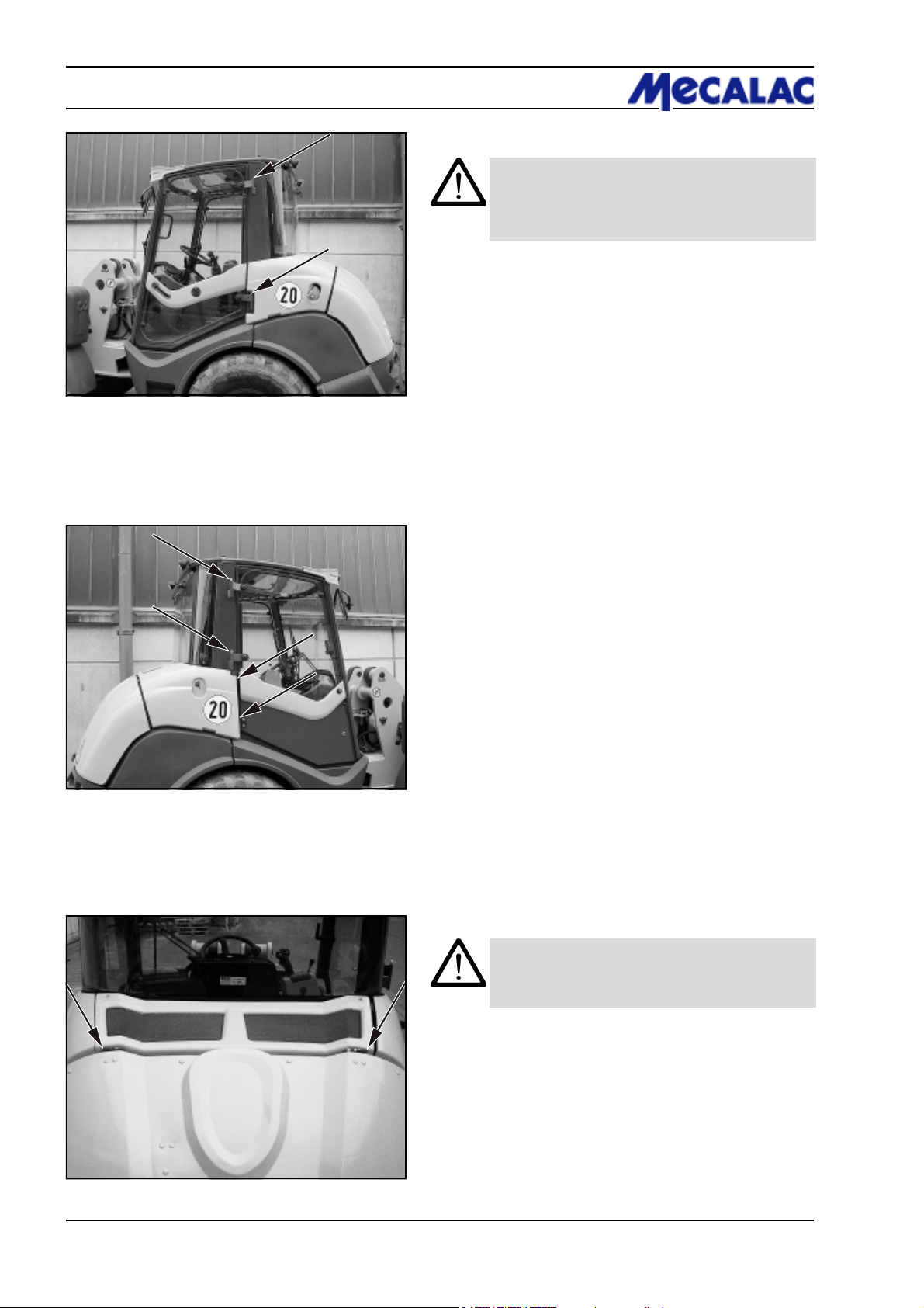
8 Maintenance
Figure 8-31
8.2.13.3 Driver’s cab doors
CAUTION
The hinges of the doors of the driver’s cabin
(8-31/arrows and 8-32/arrows) must be lubricated
every 50 operating hours.
Figure 8-32
Figure 8-33
8.2.13.4 Engine hood
CAUTION
The hinges of the engine hood (8-33/arrows)
must be lubricated every 50 operating hours.
P0700/P0710/P0850/P0860/P1000/P10108-14
Page 81
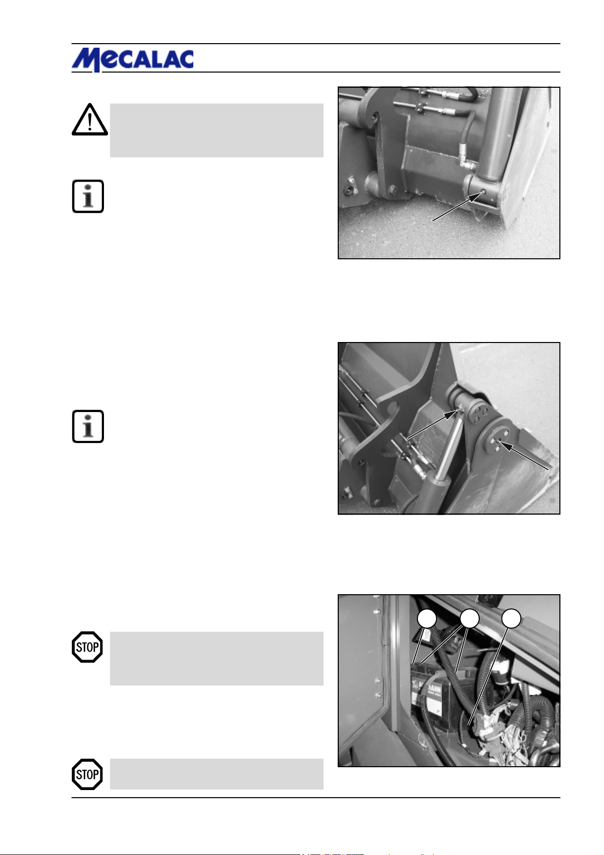
8.2.13.5 Multi-purpose bucket
CAUTION
The bearing bolts of the multi-purpose bucket
(8-35/arrows) must be greased every 10 ope-
rating hours.
NOTE
The bolts must be greased on both sides of the
multi-purpose bucket.
8.2.14 Oil lubrication points
Lubricate the following items with oil every 50 operating
hours:
- The door locks,
- the Bowden cable and leverage of the accelerator
pedal.
Maintenance 8
Figure 8-34
8.2.15 Replacing the starter battery
NOTE
The starter battery is a maintenance-free part
according to DIN 72311, section 7. It is located
behind the maintenance flap at the loader right.
(1) Opening the window: First pull the window handle
inwards, then push it outwards. Finally lift the window
handle out of its holder.
(2) Open the maintenance flap with a square wrench.
(3) Unlock the battery main switch (opt.) (8-36/1) by
giving it 2 counter clockwise turns.
(4) Loosen and remove the fastening screw (8-36/3)
(size 17) of the battery holder.
(5) Swing up the cover of the front terminal loosen and
disconnect terminals (8-36/2) from the battery (size 13).
DANGER
Always remove the negative terminal first and
then the positive terminal. Installation is in reverse
order.
Figure 8-35
1 32
(6) Remove the battery and replace it.
(7) Apply grease to the terminals before fastening them.
(8) Installation is in reverse order.
DANGER
Make sure the fastenings are secure.
Figure 8-36
P0700/P0710/P0850/P0860/P1000/P1010 8-15
Page 82
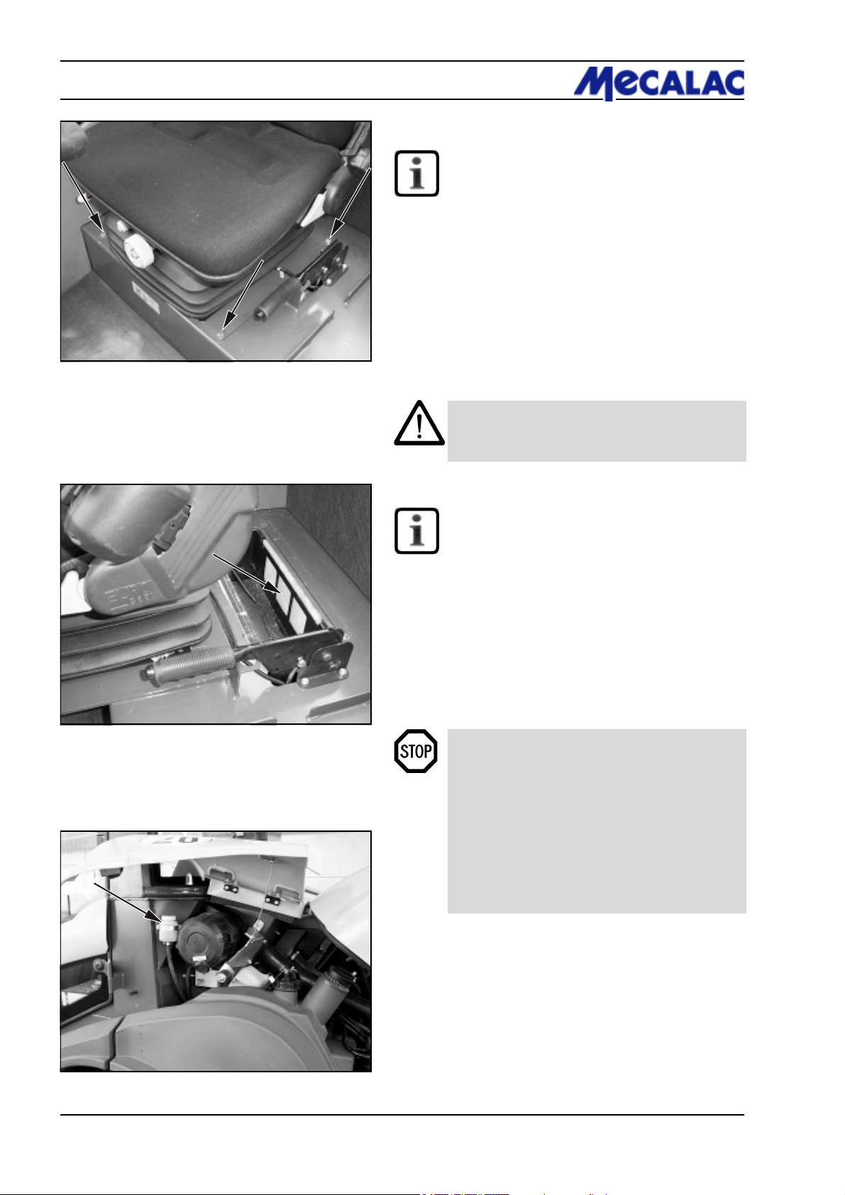
8 Maintenance
8.2.16 Maintaining/replacing the fresh air filter
NOTE
The fresh air filter is located in the driver’s cabin
underneath the seat plate.
(1) Tilt the backrest of the seat completely forward
(5-9/4).
(2) Loosen the four screws (8-37/arrows) holding the seat
plate.
(3) Pull or tilt the driver’s seat with the seat plate all the way
forward.
Figure 8-37
Figure 8-38
(4) Remove the filter cartridge (8-38/arrow) and clean it
using “mild” compressed air.
CAUTION
Do not use any petrol, hot fluids or industrial
compressed air for cleaning.
(5) Check the filter element for damage.
NOTE
The filter element must be replaced when it is
damaged (check every 500 operating hours),
but at least every 1500 operating hours.
(6) Insert the filter element, push the seat plate into the
assembly position and secure again.
8.2.17 Checking/adjusting the service/
parking brake
DANGER
- Check the combined service/parking brake
every 500 operating hours and adjust it if
necessary (see repair instructions).
- All work on the brake system must only be
carried out by authorised personnel.
- Oil loss (leaks) in the brake system must be
immediately reported to authorised personnel.
- Operation of the loader must be stopped immediately if the pedal can be pressed down too far
or the braking effect decreases noticeably.
Figure 8-39
(1) Check the fluid level on the compensation tank for
brake hydraulic oil (8-39/arrow) and top up brake hydraulic
oil if necessary.
(2) Check the pedal travel.
(3) Check the entire system for proper functioning and
absence of leaks (visual test).
P0700/P0710/P0850/P0860/P1000/P10108-16
Page 83

Faults, causes and remedies
Page 84

9 Faults, causes and remedies
9 Faults, causes and remedies
NOTE
*) Faults may be eliminated only by authorised personnel
Fault
Engine
Engine does not start.
Alternator does not charge
The bucket arm cannot be lifted/
lowered
Probable cause
Drive switch (4-10/11) is not in neutral position
Loose connection
V-belt torn
Alternator speed too low
Pressure-relief valve in servo valve is
open
Pilot valve for working hydraulics
(4-8/4) is locked
Pilot pressure too low or does not
exist
Remedy
See the operating instructions for the
engine
Set drive switch to neutral
position
Press in and lock connection
Replace V-belt
Check V-belt tension, tighten if
necessary
Remove and clean entire pressurerelief valve, readjust*
Remove the lock lever (4-8/6)
Open, clean and readjust pressurerelief valve in control line *
Steering is sluggish
Faults in the driving and working
hydraulics
Faults in the braking system
Diesel engine failed
Pressure-relief valve in steering unit
is open
Slide in priority valve stuck
Clogged filter
Lack of oil in hydraulic oil reservoir
Electrical connection at axial piston
pump are not tight, are not connected
or are oxidised
High-pressure valves soiled
Parking brake does not hold the device
Storage pressure can be used to bring
the bucket arm to its lowermost position
immediately after an engine failure.
» Does not apply when pipe break
protection is installed «
Remove and clean entire pressurerelief valve, readjust*
Replace priority valve *
Replace filter cartridge
(chapter 8.2.12)
Top up oil
Establish or clean connections
according to electric wiring diagram
Clean
Check setting, adjust if necessary*
Check whether electrical traction
drive interruption is connected to
brake lever
9-2
P070/P071/P085/P086/P100/P101
Page 85
Faults, causes and remedies 9
Fault
Heating/ventilation/air condition failed
Hose couplings of attachments
cannot be connected
Fuse in fuse box blown
Increased pressure due to heating of
the attachment
Increased pressure in basic machine
RemedyProbable cause
Replace fuse
Carefully loosen the screwed
connection on the end of the hose
using the quick-change couplings.
Oil squirts out and the increased
pressure is eliminated. Tighten the
screwed connection.
NOTE
Waste oil must be disposed
of in such a way that it will
not cause pollution!
Eliminate pressure from the lines by
alternately actuating the pilot valve
for the auxiliary hydraulic system
(4-8/5) several times.
P070/P071/P085/P086/P100/P101 9-3
Page 86

Page 87

Circuit diagrams
Page 88
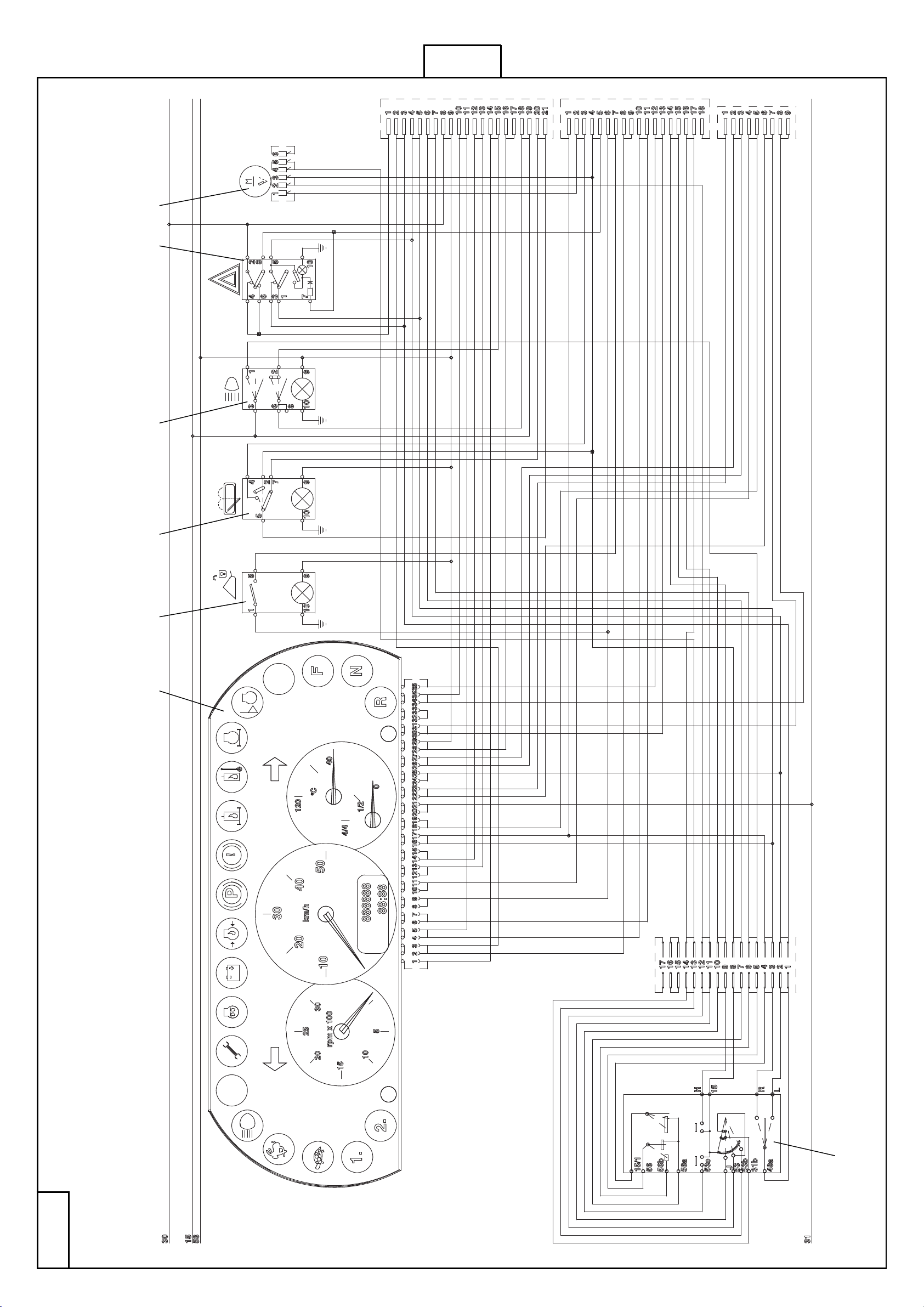
2 - 4
X1
X2
X2a
P078/P079/P088/P089/P108/P109
1 2 3 4 5 6
1 - 4
Elektrik-Schaltplan/Schéma électrique/Wiring diagramm/Elektrisch schakelschema/El-oversigt/Elektriskdiagram/
Diagrama de conexiones eléctricas/Elektrisk koblingsskjema/El-kopplingsschema/Esquema de circuitos eléctricos/
Sähkökytkentäkaavio
10.1- 06.2008
7
10-3
Page 89

10.1 Electric circuit diagram
Sheet/item Designation
1-4/1 Multifunction panel
1-4/2 Actuator: release of quick-change device
1-4/3 Actuator: rear window wiper/washer
1-4/4 Actuator: road lights
1-4/5 Actuator: Hazard flasher
1-4/6 Windshield wiper motor, front
1-4/7 Steering column switch
Circuit diagrams 10
P0700/P0710/P0850/P0860/P1000/P1010 10-3
Page 90

10 Circuit diagrams
Sheet/item Designation
2-4/1 2-pole socket
2-4/2 Fuse 10,0 A (traction drive)
2-4/3 Fuse 7,5 A (turn signal)
2-4/4 Fuse 20,0 A (hydraulics/brake light)
2-4/5 Fuse 20,0 A (heater)
2-4/6 Fuse 20,0 A (rear window heater)
2-4/7 Fuse 15,0 A (high beam)
2-4/8 Fuse 15,0 A (low beam)
2-4/9 Fuse 5,0 A (parking light, tail light left)
2-4/10 Fuse 5,0 A (parking light, tail light right)
2-4/11 Fuse 15,0 A (hazard flasher)
2-4/12 Fuse 20,0 A (windshield wiper/washer)
2-4/13 Free
2-4/14 Fuse 20,0 A (working light)
2-4/15 Fuse 30,0 A (beacon light)
2-4/16 Maxi fuse 100,0 A
2-4/17 Maxi relay (power supply)
2-4/18 Start switch
2-4/19 Turn signal relay
2-4/20 Interval timer
2-4/21 Relay for differential lock
2-4/22 Relay, fan control
2-4/23 Traction drive cut-out relay
2-4/24 Relay for power adaptation: reverse
2-4/25 Relay for power adaptation: forward
2-4/26 Relay Alpha max.
2-4/27 Starter interlock relay
2-4/28 Acoustic buzzer, hydraulic oil temperature
P0700/P0710/P0850/P0860/P1000/P101010-4
Page 91
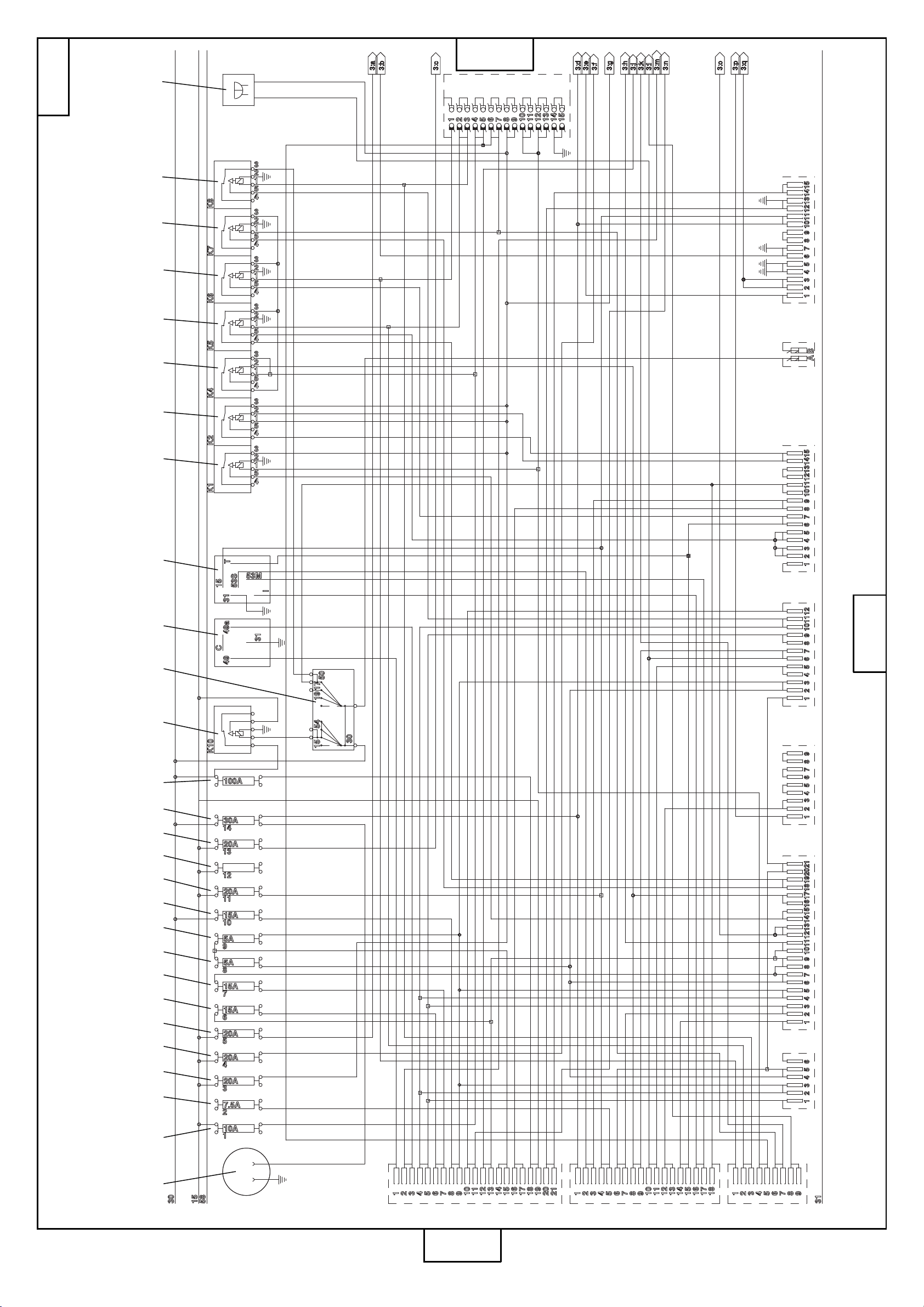
3 - 4
2 - 4
X8
10-4
4 - 4
Elektrik-Schaltplan/Schéma électrique/Wiring diagramm/Elektrisch schakelschema/El-oversigt/Elektriskdiagram/
Diagrama de conexiones eléctricas/Elektrisk koblingsskjema/El-kopplingsschema/Esquema de circuitos eléctricos/
Sähkökytkentäkaavio
X3 X4 X5 X6 X7 X7/1 X11
2 3 4 5 10 11 12 17 21 23 25 26246 7 98 13 14 15 16 19 20 22 27 281 18
10.1- 06.2008
X1
X2
X2a
P078/P079/P088/P089/P108/P109
1 - 4
Page 92
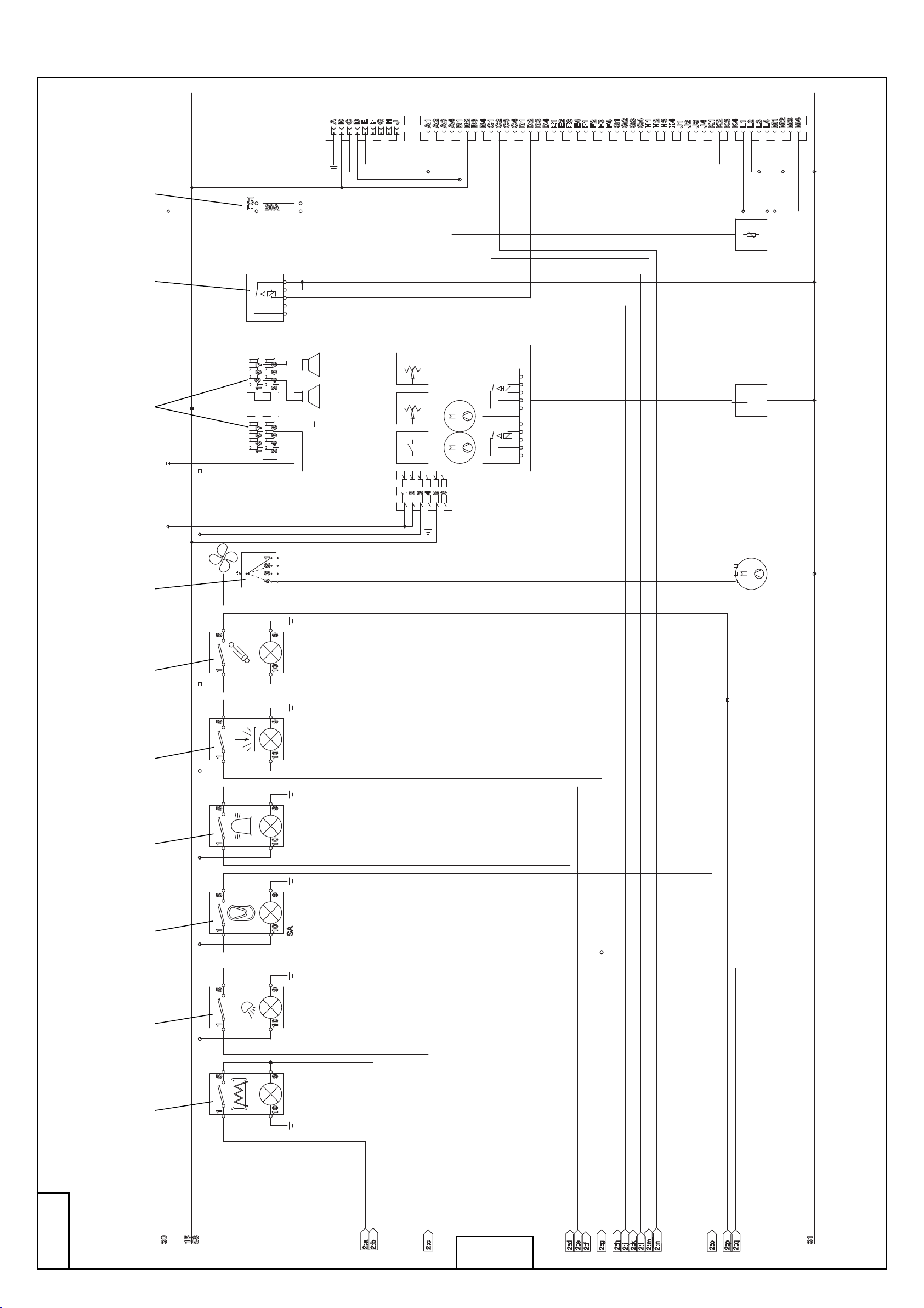
9 10
12
11
P078/P079/P088/P089/P108/P109
8
6
1314
Elektrik-Schaltplan/Schéma électrique/Wiring diagramm/Elektrisch schakelschema/Elektriskdiagram/
El-oversigt/Diagrama de conexiones eléctricas/Elektrisk koblingsskjema/El-kopplingsschema/
Esquema de circuitos eléctricos/Sähkökytkentäkaavio
1 2 3 4 5 7
10.1- 06.2008
2 - 4
3 - 4
10-5
Page 93

Sheet/item Designation
3-4/1 Actuator: Rear window heater
3-4/2 Actuator: working lights
3-4/3 Actuator: lifting device suspension (option)
3-4/4 Actuator: Warning beacon (opt.)
3-4/5 Actuator: Permanent auxiliary hydraulics (opt.)
3-4/6 Actuator: Pipe break protection (option)
3-4/7 Actuator: fan/blower
3-4/8 Radio (option)
3-4/9 Relay for controller engine
3-4/10 Fuse (20A) controller engine
3-4/11 Air-conditioning system (option)
3-4/12 Accelerator
3-4/13 Coupling, air condition compressor
3-4/14 Heater fan motor
Circuit diagrams 10
P0700/P0710/P0850/P0860/P1000/P1010 10-5
Page 94

10 Circuit diagrams
Sheet/item Desigation
4-4/1 Wiper motor, rear
4-4/2 Interior lighting
4-4/3 Switch: Interior lighting
4-4/4 Reversing buzzer
4-4/5 Working lights, rear (option)
4-4/6 Working lights, rear (option)
4-4/7 Working lights, front
4-4/8 Working lights, front
4-4/9 Warning beacon (opt.)
4-4/10 Relay, glow plugs
4-4/11 Maxi fuse (glow plugs) 100 A
4-4/12 Glow plugs
4-4/13 Starter
4-4/14 Alternator
4-4/15 Battery main switch (option)
4-4/16 Battery
4-4/17 Valve, fan control
4-4/18 Coolant temperature switch 93° C
4-4/19 Window washer motor, rear
4-4/20 Windshield washer motor, front
4-4/21 Valve, forward drive direction
4-4/22 Reversing buzzer
4-4/23 Valve, reverse drive direction
4-4/24 Reversing light, left
4-4/25 Turn signal, rear left
4-4/26 Reversing light, right
4-4/27 Turn signal, rear right
4-4/28 Tail light, right
4-4/29 Brake light, right
4-4/30 Tail light, left
4-4/31 Brake light, left
4-4/32 Dip pipe sensor
4-4/33 Switch: Hydraulic oil filter (option)
4-4/34 Switch: hydraulic oil temperature
4-4/35 Direction detection valve
4-4/36 Alpha max. valve
4-4/37 Switch: Parking brake
4-4/38 Differential lock valve
4-4/39 Memory valve, lifting device suspension (option)
4-4/40 Reservoir valve, lifting device suspension (option)
4-4/41 Valve, pipe break protection
4-4/42 Valve, pipe break protection
4-4/43 Quick-change device release valve
4-4/44 Driving light, left
4-4/45 Driving light, right
4-4/46 Signal horn
4-4/47 7-pole socket (option)
4-4/48 Lifting device suspension switch (option)
4-4/49 Brake light switch
NOTE
The bold numbers next to the item numbers in the electric circuit diagram are cross-references
to the respective part in the hydraulic diagram.
P0700/P0710/P0850/P0860/P1000/P101010-6
Page 95
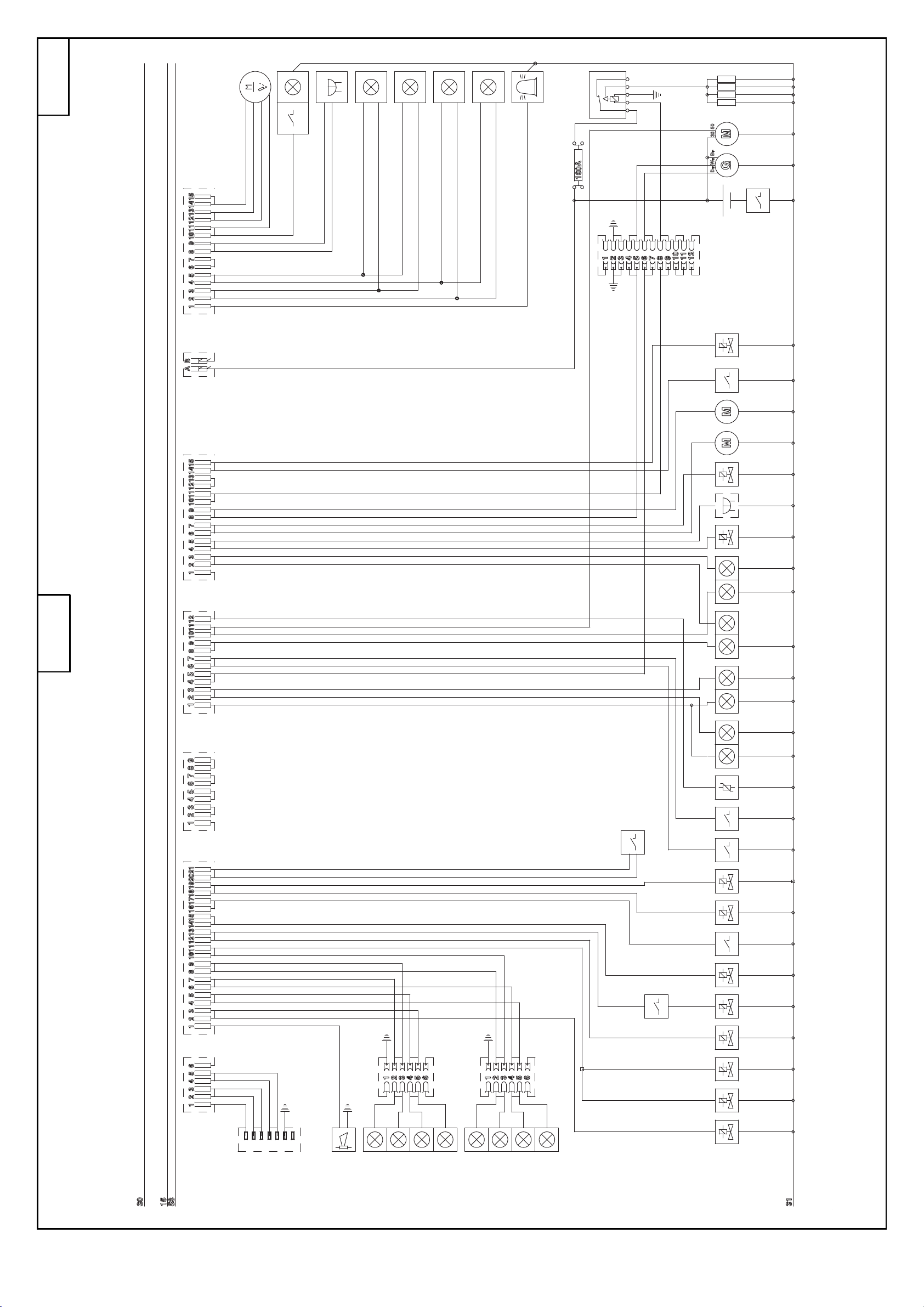
1
2
4
5
6
7
8
9
4 - 4
3
11
10
10-6
121415171920212227 132324252829303132333435
16
18
2 - 4
Y2Y3Y11Y10 Y7Y6 Y1
26
49
DS1Y4DS4
DS3
3637383940414243
48
Elektrik-Schaltplan/Schéma électrique/Wiring diagramm/Elektrisch schakelschema/El-oversigt/Elektriskdiagram/
Diagrama de conexiones eléctricas/Elektrisk koblingsskjema/El-kopplingsschema/Esquema de circuitos eléctricos/
Sähkökytkentäkaavio
X3 X4 X5 X6 X7 X7/1 X11
Y50 Y50
10.1- 06.2008
47
46
45
44
P078/P079/P088/P089/P108/P109
Page 96
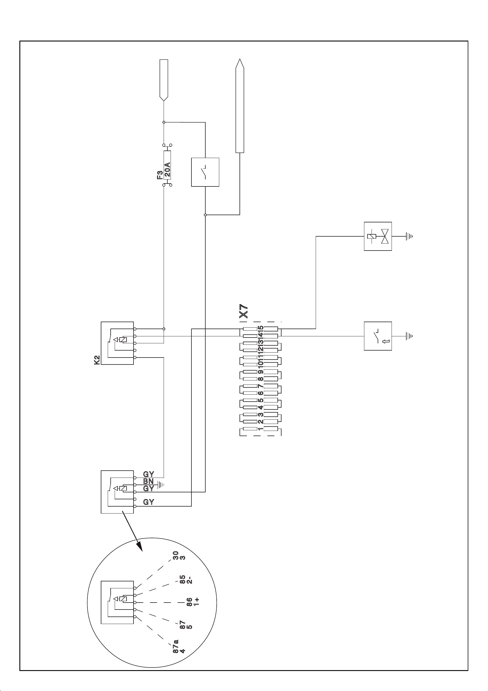
Klemme 15
)
)
E-Plan 3-4/11
(
)
E-Plan 2-4/22
(
)
E-Plan 2-4/4
(
Sicherung Lüftersteuerung
Schalter Klimaanlage
E-Plan 3-4/11
(
Klimaanlage
)
E-Plan 4-4/17
(
Ventil Lüftersteuerung
P078/P079/P088/P089/P108/P109
Relais Lüftersteuerung
Relais Lüfterschaltung
(hinter Wartungsklappe 4-13)
)
E-Plan 4-4/18
(
Kühlmitteltemperaturschalter
Elektrik-Schaltplan Klimaanlage-Lüfterschaltung
10.1.1 - 06.2009
10-7
Page 97

Page 98
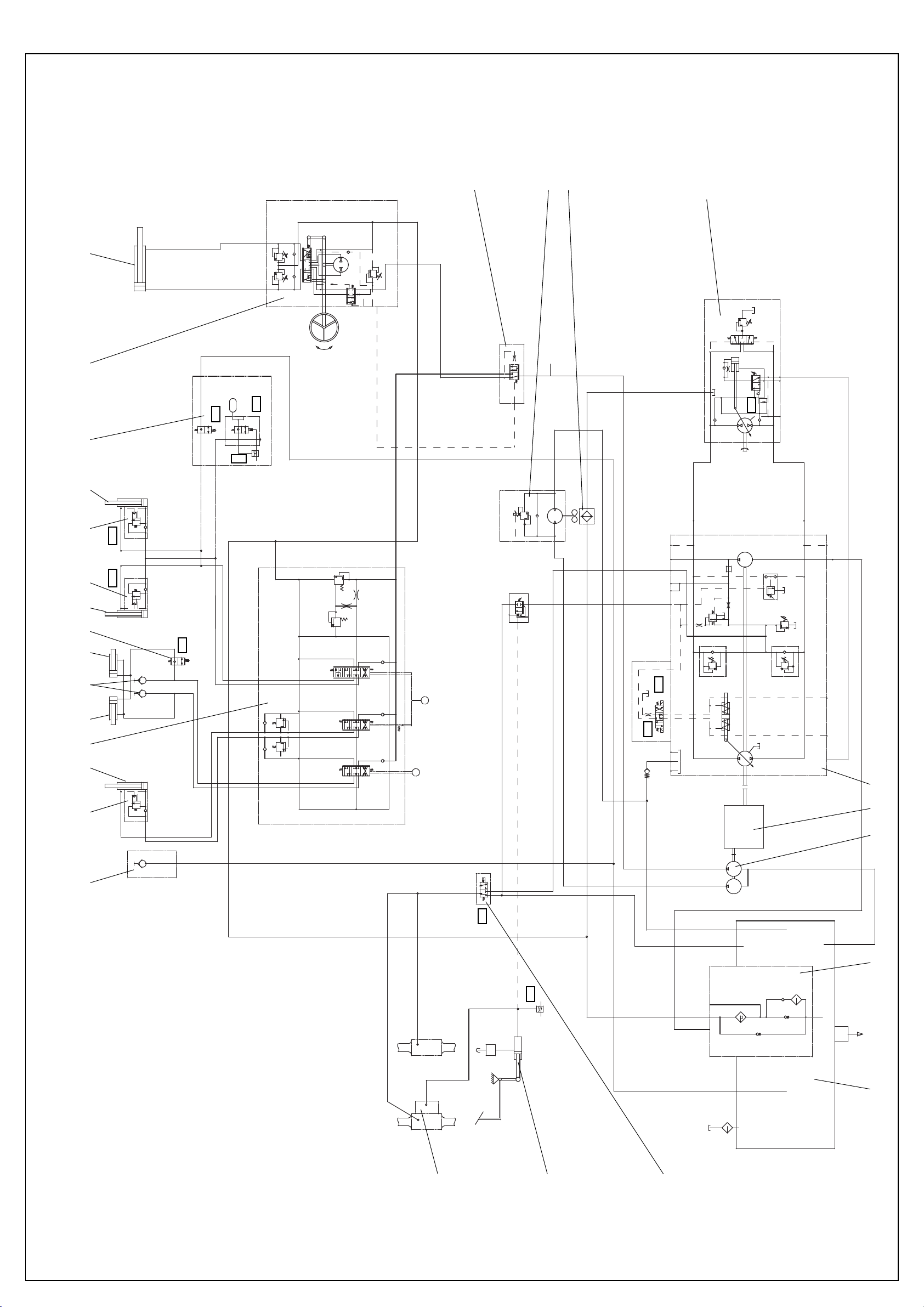
G1/2 G1/2
RL
240
M18x1,5 M18x1,5
180
13
M18x1,5 M18x1,5P T
M12x1,5 LS
14
15
16
Messanschluss
Branchement de mesure
Gauge part
Meetaansluiting
Conexión de medición
Sonderausstattung
En option
Optional equipment
Wardt niet standaard geleverd
X
..
_ _
..
_
Opción
P070/P071/P085/P086/P100/P10110-9
11
9 8
5
3 7
Y50 Y50
EF
CF
G1/2
Y7
1,0 l 35 bar
Y10
G1/2 G1/2
G1/2 G1/2
Y6
G1/2 G1/2
B
A
P
DS6
G1/2
G1/2
G1/2
G1/2
G1/2
G1/2
P
T
G1/2"
250 bar
B1
A1
B2
A2
B3
A3
270 bar
300 bar
P1
G1/2
LS
G1/4
G1/2P
T
B
SAE 1"
R
B
A B
T
P
Y
G3/4 G3/4
X
MB
M12x1,5
G
M12x1,5
M12x1,5
Y2
a
PS
(SAE 3/4")
8,6 cm³/U
10 bar
+
P = 480
T
Y3
U G
M12x1,5 M14x1,5 M18x1,5SAE 1"
A
A
(SAE 3/4")
MA
M12x1,5
S
M33x2
P = 455 +10 bar
P = 25 bar
10 bar
+
P = 480
X2
M12x1,5
X X X
Y1
3 bar
b
M22x1,5
40 cm³/U
R T1
M12x1,5
T2
M22x1,5
X1
M12x1,5
1721 20
1819
G1/2
X
P
22 cm³/U
S
P
1 2 4 6 5 8 9 10 12
Y11
DS3
M14x1,5
E
M10x1
M10x1,0
M14x1,5
A
Hydraulikschaltplan/Schéma hydraulique/Hydraulisch schakelschema/Hydraulic circuit diagram/Hydraulikoversigt/Plano de conexiones hidráulicas/Hydraulikdiagram
Hydraulisk koblingsskjema/Hydraulik kopplingsschema/Plano de circuitos hidráulicos/Hydraulikk-koplingsskjema/Hydrauliikkakytkentäkaavio
AX 700 / AX 850 / AX 1000
E
G1
B A
G1
10 muem.
S
10 muem.
4 cm³/U
2,5 bar
125 muem.
0,5 bar
10.2 - 06.2009
24
23
22
Page 99

Circuit diagrams 10
10.2 Hydraulic circuit diagram
Item Designation
01 Unpressurised return line (option)
02 Pipe break protection, tip cylinder (option)
03 Tip cylinder:
AX 700 - DW 90/50/424/1480 AX 700 High lift - DW 100/50/424/1700
AX 850 - DW 90/50/424/1480 AX 850 High lift - DW 100/50/424/1700
AX 1000 - DW 100/50/424/1480 AX 1000 High lift - DW 100/50/424/1700
04 3-way valve
05 Locking cylinder DW 40/25/50/167
06 Auxiliary hydraulics
07 Valve, quick change device lock
08 Lift cylinder
AX 700 - DW 70/40/600/876 AX 700 High lift - DW 80/40/561/924
AX 850 - DW 80/40/600/876 AX 850 High lift - DW 100/45/600/895
AX 1000 - DW 90/45/600/876 AX 1000 High lift - DW 100/45/600/895
09 Pipe break protection, lift cylinder (option)
10 lifting device suspension (option)
11 Steering unit, 320/160 cm³/rev.
12 Steering cylinder DW 80/35/295/585
13 Priority valve
14 Fan motor
15 Hydraulic oil cooler
16 Drive motor:
AX 700/20 km/h, AX 850/20 km/h - A6VM 80 HA
AX 700/30 km/h, AX 850/30 km/h, AX 1000 - A6VM 107 HA
17 Drive pump A4VG 40 DA
18 Drive engine:
AX 700, AX 850 - John Deere 4024HF295A / 46.0 kW / 2800 rpm
AX 1000 - John Deere 4024HF295B / 49,0 kW / 2800 rpm
19 Tandem gear pump, 32/4 cm³/rev.
20 Combined suction and return flow filter
21 Hydraulic oil tank
22 Differential lock
23 Main brake cylinder
24 Drum brake
- AX 700 - 20 km/h
- AX 850 - 20 km/h
Disc brake
- AX 700 - 30 km/h
- AX 850 - 30 km/h
- AX 1000
option = Special equipment
P0700/P0710/P0850/P0860/P1000/P1010 10-7
10-9
Page 100

 Loading...