


User Manual
Original instructions
Meca500
Document version: 4.5
Robot firmware: 6.0.9
September 1, 2017

The information contained herein is the property of Mecademic Inc. and shall not be
reproduced in whole or in part without prior written approval of Mecademic Inc. The
information herein is subject to change without notice and should not be construed as a
commitment by Mecademic Inc. This manual will be periodically reviewed and revised.
Mecademic Inc. assumes no responsibility for any errors or omissions in this document.
Copyrightc 2017 by Mecademic Inc.

Contents
1 Introduction 1
2 Warning messages, notes and emphasis 1
3 What’s inside the box 2
4 Safety 3
4.1 Installing a Category 0 emergency stop . . . . . . . . . . . . . . . . . . . . . 4
4.2 Disabling the robot brakes . . . . . . . . . . . . . . . . . . . . . . . . . . . . 4
5 Installing the Meca500 5
6 Installing an end-effector 7
7 Operating the robot 9
7.1 The web interface . . . . . . . . . . . . . . . . . . . . . . . . . . . . . . . . . 9
7.1.1 Overview . . . . . . . . . . . . . . . . . . . . . . . . . . . . . . . . . 9
7.1.2 Connection and disconnection . . . . . . . . . . . . . . . . . . . . . . 10
7.1.3 The programming panel . . . . . . . . . . . . . . . . . . . . . . . . . 11
7.1.4 The robot’s log panel . . . . . . . . . . . . . . . . . . . . . . . . . . . 13
7.1.5 The CAD models import panel . . . . . . . . . . . . . . . . . . . . . 13
7.2 Power-up procedure . . . . . . . . . . . . . . . . . . . . . . . . . . . . . . . . 14
7.2.1 Connecting to the robot . . . . . . . . . . . . . . . . . . . . . . . . . 14
7.2.2 Activating the robot . . . . . . . . . . . . . . . . . . . . . . . . . . . 15
7.2.3 Homing the robot . . . . . . . . . . . . . . . . . . . . . . . . . . . . . 15
7.2.4 Enabling joint and pose feedback . . . . . . . . . . . . . . . . . . . . 15
7.3 Moving the robot . . . . . . . . . . . . . . . . . . . . . . . . . . . . . . . . . 15
7.4 Power-off procedure . . . . . . . . . . . . . . . . . . . . . . . . . . . . . . . . 17
7.4.1 Re-zeroing the robot (optional) . . . . . . . . . . . . . . . . . . . . . 17
7.4.2 Deactivating the robot . . . . . . . . . . . . . . . . . . . . . . . . . . 18
7.4.3 Disconnecting the robot . . . . . . . . . . . . . . . . . . . . . . . . . 18
7.4.4 Removing power . . . . . . . . . . . . . . . . . . . . . . . . . . . . . 18
7.5 Offline mode . . . . . . . . . . . . . . . . . . . . . . . . . . . . . . . . . . . . 18
7.5.1 Saving the program via the web client interface . . . . . . . . . . . . 18
i

7.5.2 Running the offline program . . . . . . . . . . . . . . . . . . . . . . . 19
7.6 Robot’s control panel . . . . . . . . . . . . . . . . . . . . . . . . . . . . . . . 19
7.6.1 LEDs . . . . . . . . . . . . . . . . . . . . . . . . . . . . . . . . . . . 19
7.6.2 Buttons . . . . . . . . . . . . . . . . . . . . . . . . . . . . . . . . . . 20
8 Examples 22
8.1 Draw a square . . . . . . . . . . . . . . . . . . . . . . . . . . . . . . . . . . . 22
9 Troubleshooting 23
10 Storing the robot in its shipping box 24
11 EC Declaration of Incorporation (original) 25
ii

User Manual
1 Introduction
There are two manuals that come with the Meca500: this one and the programming manual.
This manual will guide you through the steps required for setting up your Meca500 industrial
robot and for using it in a safe manner. You must read this user manual thoroughly before
even unpacking your first Meca500.
The Meca500 is a six-axis industrial robot arm that is relatively easy to use, robust and
lightweight. The robot is, however, a precision device with rapidly moving parts. This
robot should therefore be used only by technical personnel who have read and understood
every part of this user manual in order to avoid damages to the robot, its end-effector, the
workpiece and adjacent equipment, and, most importantly, in order to avoid injuries.
2 Warning messages, notes and emphasis
Particular attention must be paid to the warning messages in this manual. There are only
two types of warning messages, as shown bellow:
WARNING:
B
B
In addition, important notes and definitions are formatted as follows:
This presents instructions that must be followed in order to prevent injuries
and possibly damage to your robot cell (robot arm, power supply, end-effector,
workpiece and/or adjacent equipment).
CAUTION:
This presents instructions that must be followed in order to prevent damage
to your robot cell (robot arm, power supply, end-effector, workpiece and/or
adjacent equipment).
NOTICE:
This highlights important suggestions or definitions, the purpose of which is to
improve the understanding of this manual and of how the robot works.
Finally, occasionally, small portions of the text in this manual that are particularly important
are underlined (as already done in the previous section).
Copyrightc 2017 by Mecademic Inc. Page 1 of 25

User Manual
3 What’s inside the box
Your shipping box contains a Meca500 robot arm (Fig. 1a), a 2-meter Ethernet cable (Fig. 1b,
model MDE45-4MP-RJ45-2M from Mencom Corp.), and a desktop 24 V DC power supply
(Fig. 1c) with IEC 320 C14 connector. (You must provide your own AC power cord.) Your
box may also contain the MEGP 25 electric gripper. Remove all items carefully and do
not discard your shipping box. If your order contained a gripper, do not open its package
immediately.
(a) The Meca500 robot arm (b) Ethernet cable (c) Power supply
You must read the MEGP 25 user manual prior to installing the gripper.
Figure 1: The contents of your shipping box (optinal gripper not shown)
CAUTION:
B
Page 2 of 25 Copyright
• Handle the robot with care.
• The Meca500 is equipped with brakes on the first three joints (the ones close
to the base). When the robot is not activated, these brakes are automatically
applied. Do not force the brakes of the robot, unless there is an emergency!
• Inspect the robot and the power supply for damages. If you think either of
them is damaged, do not use the robot and contact us immediately.
• Do not modify or disassemble the robot.
• Do not modify the power supply.
• Do not use or store the Meca500 in a humid environment.
• Do not operate the Meca500 at temperatures bellow +5◦C or above +45◦C.
c
2017 by Mecademic Inc.

User Manual
4 Safety
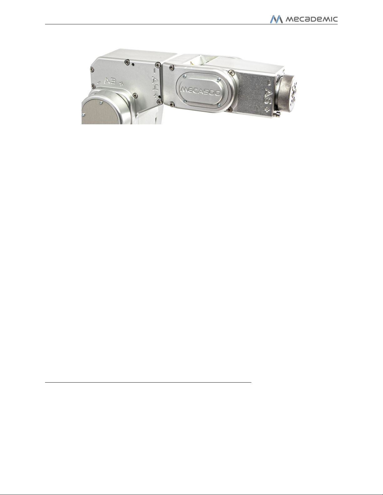
The Meca500 weighs less than 5 kg. It can, however, move relatively fast and may cause
injuries, especially when certain end-effectors are attached to its flange (e.g., a sharp tool or
a laser). The robot also has pinch regions where two adjacent links of the robot can squeeze
a finger (Fig. 2).
Figure 2: The zones labeled with the pinch-point warning sign can lead to injuries
It is imperative that you follow the guidelines of ISO 12100:2010 and ISO 10218-2:2011
and conduct a risk assessment of your complete robot cell, including the Meca500, its endeffector and all adjacent equipment.
In the near future, we will implement force limitation routines to make the Meca500 truly
collaborative and enable the hand guiding (lead-through) programming mode. Until then,
the following general safety rule must be respected:
WARNING:
B
Copyrightc 2017 by Mecademic Inc. Page 3 of 25
When the Meca500 is activated, stand away from it, wear safety goggles and be
attentive and alert. If deemed necessary, place the robot in a safety enclosure.

User Manual
4.1 Installing a Category 0 emergency stop
The Meca500 can be equipped with an emergency stop of Category 0 only. Such a stop must
be installed on the AC part of the power supply, e.g., by modifying the IEC power cord.
CAUTION:
B
When disconnecting the AC power, the robot brakes on joints 1, 2 and 3 are immediately
applied and the joints are immobilized instantly, while the wrist joints of the robot become
free. This minimizes the risks of pinning and pinching from the wrist and end-effector.
However, beware that the end-effector might slowly move downwards under the effects of
gravity. Depending on the type of end-effector used, this residual motion might lead to an
injury.
Never install an emergency stop or any kind of on/off switch on the DC side of
the power supply.
4.2 Disabling the robot brakes
In case of a collision, you can disable the brakes of joints 1, 2 and 3. This can only be done
if the robot is powered AND not activated. How to activate and deactivate the robot is
explained later in this manual, but for now, it suffices to say that the robot is deactivated
after a power-up. Thus, in case of a collision, you can simply cut the AC power (e.g., by
unplugging the cable cord), then reconnect it again, and wait for the LEDs on the robot’s
base to stop flashing. However, it would be better to directly deactivate the robot, without
powering it off first.
To release the brakes of joints 1, 2 and 3, once the robot is powered but not activated,
press one of the two buttons on the base of the robot continuously while holding the robot
with your other hand. After 3 seconds, you will hear the deactivation of the brakes. Continue
holding the 0G button pressed and move the robot as far as possible from obstacles. Finally,
release the 0G button, and move away from the robot. Note that there is a pair of commands
to disable and re-enable the brakes. These are described in the Programming manual.
WARNING:
B
Page 4 of 25 Copyright
In case of an emergency, it is relatively easy to force the robot brakes and move
the robot. However, forcing the brakes too often will damage the robot.
c
2017 by Mecademic Inc.

User Manual
5 Installing the Meca500
You are surely eager to start using your Meca500. It is, however, imperative that you fix
solidly the base of your robot arm before activating the robot.
WARNING:
B
In other words, do not fix the robot on an inclined or vertical surface (e.g., a wall). Note
that the robot will automatically detect the angle between the axis of joint 1 and the gravity
vector and if this angle is not in the range [0◦, 3◦] or [177◦, 180◦], the robot will not function.
The following steps must then be executed before you can start using your Meca500:
1. Attach the circular connector of the Ethernet cable to either of the two Ethernet ports
2. Connect the un-powered power supply to the robot’s DC power connector (Figs. 3b-c).
Fix securely the robot’s base via the mounting holes (Fig. 3a) with M6 screws,
in either upright or downright position, on a horizontal, flat surface of a rigid,
stationary and steady body.
on the robot’s base and connect the RJ-45 jack to your computer or router (Figs. 3b-c).
The two ports act as a bridge, so you can daisy chain several Meca500 robots.
Make sure the connector is completely screwed, or else you may damage the robot’s
controller. Then, connect the power supply to the country-specific AC power cord.
Finally, connect the AC power cord to an AC outlet.
CAUTION:
B
4. The robot’s LEDs should now start flashing for a few seconds while the robot controller
5. Depending on which of the two Ethernet ports was used in step 1, the Link/Act IN
Copyrightc 2017 by Mecademic Inc. Page 5 of 25
• Do not use any other power supply but the one provided, or else the warranty
will be voided and the CE certification no longer valid.
• Always connect the power cable to the Meca500 before connecting the power
supply to an AC outlet.
• Always disconnect the power supply from the AC outlet before disconnecting
the power cable from Meca500.
• Avoid un-plugging the power supply from the robot’s DC power connector
too often and always make sure the connector is completely screwed.
is booting. When the controller is ready, the red LED will start flashing intermittently.
or Link/Act OUT green LED should be illuminated. If it is not, detach the Ethernet
cable and repeat step 1.

User Manual
115
90
100
75
4X thru holes for M6
units: mm
DC power connector
Ethernet ports
(a) Dimensions
(c) Connectors properly attached
(b) Connectors
Figure 3: The base of the Meca500
6. Configure your computer with a static IP address. The way to do this differs from one
operating system to another. Figure 4 shows how to do this in Windows and in Linux.
7. Open a web browser, the latest version of either Google Chrome or Firefox only, and
type Meca500’s default IP address 192.168.0.100 in the address bar.
8. Meca500’s web interface should load instantaneously. If it doesn’t, repeat the previous
through the robot’s web interface, which will be described in detail in Section 7. Here is the
procedure for doing so:
Page 6 of 25 Copyright
step with a different browser.
It is also possible to change the robot’s network configuration. This option is available
1. Click on the Options dropdown menu and on Settings.
2. Depending on your actual configuration, choose DHCP to automatically receive an
address from your router or Static to force a specific IP. You don’t need to reboot the
robot; the new configuration will be applied as soon as you click on the Save button.
c
2017 by Mecademic Inc.

User Manual
(a) Windows (b) Linux
Figure 4: Two examples of how to configure the IP address of your computer
Figure 5: Options dropdown menu
6 Installing an end-effector
The Meca500 comes with a proprietary tool I/O (input/output) port located at the robot’s
extremity. However, this tool port is reserved uniquely for our electric gripper MEGP 25.
Under no circumstances will we share the pinout of this port or its custom-made communication protocol. To install our gripper, refer to its User Manual.
If you want to use any other end-effector with the Meca500, you will need to control it
independently from the Meca500. You can attach the cabling of your end-effector along the
robot arm using adhesive-backed tie mounts. Finally, you must fix the end-effector to the
robot’s flange (Fig. 7a) using four M3 screws and, optionally, two 3 locating pins, all of
properly selected length. The following rules should be respected.
WARNING:
B
• Keep the robot un-powered while installing/removing a tool to its flange.
• Do not overpass the robot’s payload (0.5 kg).
• Securely fasten the tool to the robot’s flange.
Copyrightc 2017 by Mecademic Inc. Page 7 of 25

User Manual
Ø36
Ø8 H7, É2
M3X0.5, É3.5
BCD 24
4X equally spaced
Ø3 H7, É3.5
BCD 15.5
2X equally spaced
units: mm
(a) DHCP (b) Static
Figure 6: Two ways to change the robot’s network configuration
flange is closest to the tool I/O port. In the view of the flange shown in Fig. 7a, the stopper
pin would be on the right.
(a) Dimensions (b) Closeup
Figure 7: The mechanical interface (flange) of the Meca500
Note that when joint 6 is zero degrees, as in Fig. 7b, the stopper pin on the back of the
CAUTION:
B
• Do not over-tighten the M3 screws. Furthermore, do not screw them more
than 3.5 mm into the flange, or else you will damage the gearbox of joint 6.
• Make sure that if you use 3 locating pins, they do not penetrate more than
3.5 mm into the flange, or else you will damage the gearbox of joint 6.
• Attach the tool cabling in such a manner that it does not obstruct the motions
of the robot.
• Unless you plug the connector of our own gripper, keep the cover (screw cap)
of the I/O port (not shown in Fig. 7b) in place at all times.
Page 8 of 25 Copyright
c
2017 by Mecademic Inc.

User Manual
7 Operating the robot
7.1 The web interface
Meca500’s web interface is more or less the equivalent of the teach pendant’s interfaces
of traditional industrial robots. The interface is essentially an HTML 5 web page with
JavaScript and WebGL code and the CAD models of the robot links, and potentially the
end-effector and the environment (in binary STL format). All of these files reside in the
robot’s controller, so you don’t need to install anything on your computer.
The interface basically translates your mouse clicks and keyboard entries into proprietary
commands that are sent to the robot’s controller. These are the same commands described in
the Programming manual that you will eventually start sending from your own application,
written in C++, Java, Python or any other programming language that supports Ethernet
socket messaging. In addition, the web interface displays the feedback messages received
from the robot and, generally, the virtual model of the actual robot.
The web interface is intended mainly for testing and writing simple programs. You must
create your own software application or program if you intend to use the robot for complex
tasks, such as interacting with inputs and outputs (in which case you also need a third-party
I/O module).
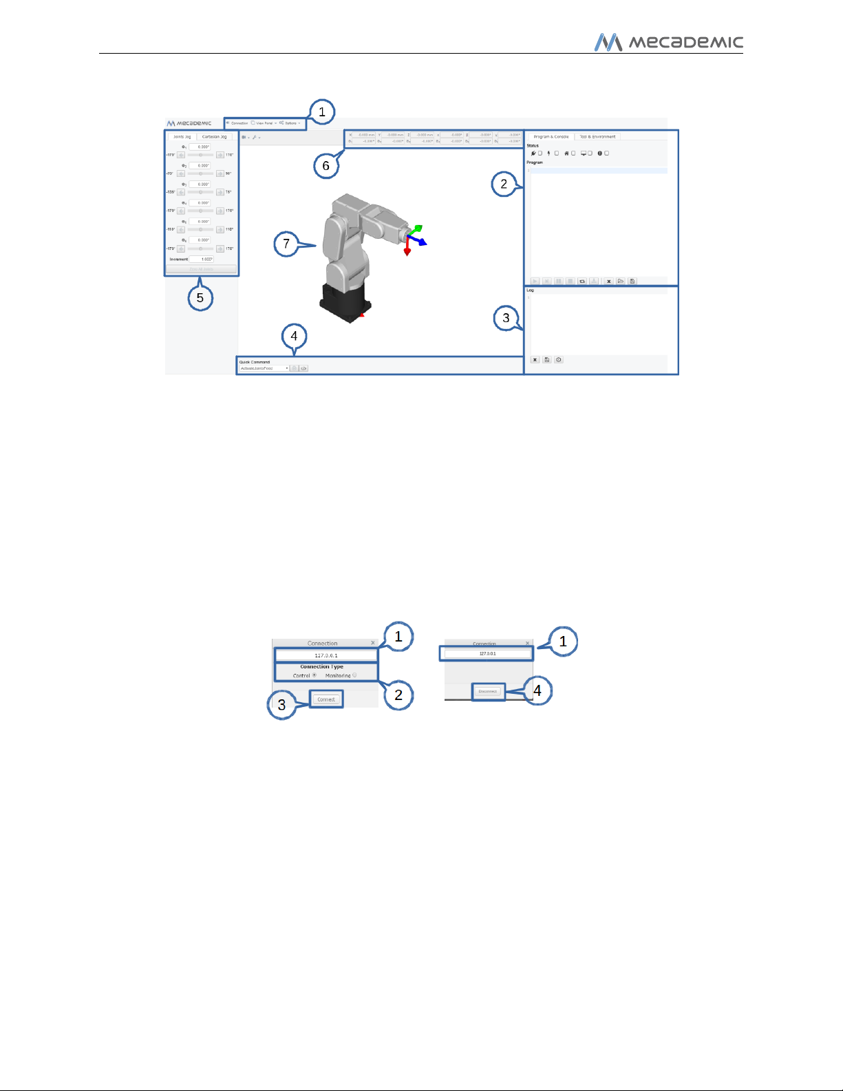
7.1.1 Overview
Figure 8 shows the main elements of the web interface. These are:
1. The main menu
2. The programming panel
3. The robot’s log panel
4. The quick command panel
5. The real-time jogging panel
6. The real-time pose of the robot’s end-effector and
joint positions.
7. The 3D view of the robot, which move in real-time
when the joint feed is activated (( icon checked).
Copyrightc 2017 by Mecademic Inc. Page 9 of 25
User Manual
Figure 8: Overview of Meca500’s web interface
7.1.2 Connection and disconnection
Once the web interface is loaded, the first step is to connect it to the robot. So far, you’ve
just established an HTTP connection with the robot, but not activated the socket messaging
which is the only communication channel for controlling the robot. You can connect to the
robot by either selecting the J checkbox in the programming panel, or by selecting the
Connection menu item in the main menu.
Figure 9: Connect/disconnect windows
The windows displayed in each of these two cases are shown in Fig. 9. The elements of
these windows are:
1. IP address of the robot, which is automatically set
2. Connection type, which is either Control for sending commands to the robot or Mon-
itoring for getting a real-time view of robot’s motion
3. Connection button
4. Disconnect button
Page 10 of 25 Copyright
c
2017 by Mecademic Inc.

User Manual
For now, leave the Control radio button in the Connect window selected. The Monitoring
option is explained in the Programming manual.
7.1.3 The programming panel
The programming panel is used mainly for writing and executing very simple programs,
i.e., for testing. These programs are sequences of the proprietary commands described in
the Programming manual. Meca500’s command interface does not support conditionals,
loops, or other flow control statements. The robot only accepts request commands (to get
information from the robot) and motion commands (to tell the robot to perform an action).
The panel also supports comments in C/C++ style (e.g., // and /* */).
For complex tasks, you must write a program outside the web interface (e.g., in your
preferred integrated development environment) that parses the robot’s feedback, controls
the robot, and handles all flow control logic. For this, you can use any language that
supports communication over TCP/IP (e.g., C/C++, C#, Python, Java or even Structured
Text, in the case of a PLC).
Figure 10: The programming panel
Figure 10 shows the programming panel. The different elements of this panel are enumerated bellow:
1. Connection/disconnection checkbox, J
2. Activation/deactivation checkbox, í
3. Homing checkbox,
Copyrightc 2017 by Mecademic Inc. Page 11 of 25
User Manual
Figure 11: Joints 4, 5 and 6 being at their zero positions
4. Real-time position data feed checkbox (required if you want to jog the robot), (
5. Error status and error reset checkbox, <
6. Send and execute program button, ¿
7. Send the line command where the cursor is, and move it to the next line, ÿ
8. Hold motion (pauses and keeps the current program; motion is restarted with the ¿
button), ·
9. Clear motion (delete all commands and stops the motion),
10. Loop the program, Û
11. Save the program in the robot for offline execution (Section 7.5), /
12. Delete all entries in the program text field, Ï
13. Open an existing program, c
14. Save the contents of the program text field to a file, à
15. Programming text field
Now, after having connected the web interface to the robot’s controller, you need to
activate the robot. This can be done by selecting the í checkbox, in the programming
panel. Next, you need to home the robot. Indeed, since the Meca500 is not equipped with
truly absolute encoders, it needs to perform a homing procedure every time you activate it.
Make sure that joint 4 is close to its zero positions, as in Fig. 11. If the joint is not within
the range ±90◦, rotate it manually.
During homing, joints 1, 2 and 3 will first go close to their zero positions, then rotate up
to about 3◦, then go exactly to their zero positions. Next, joints 4 and 5 will do the same,
but the small rotations will be up to about 7◦. Finally, joint 6 will rotate in the positive
sense until it reaches its “upper” mechanical limit, then go directly to its exact zero position.
Page 12 of 25 Copyright
c
2017 by Mecademic Inc.

CAUTION:
User Manual
B
Homing the robot can be done by selecting the checkbox in the programming panel.
The robot will start moving, first joints 1, 2 and 3, then joints 4 and 5, and finally joint 6.
The robot will en up in the position shown in the photo on the cover page of this manual.
7.1.4 The robot’s log panel
The robot’s log panel (Fig. 12) displays all the messages that are sent by the robot. The
elements of this panel are self explanatory:
1. Clear the log, Ï
2. Save the log, à
3. Display timestamp for each message,
4. Log field
Before homing the robot, make sure that there is no risk for mechanical interference.
Figure 12: Robot log panel
7.1.5 The CAD models import panel
One particularly innovative and original functionality of Meca500’s web interface is the
possibility to upload CAD models for the robot’s tool (end-effector) and environment. These
models should be in binary STL format. Currently, they serve only for visualization purposes,
but in the very near future, they will be used for avoiding mechanical interferences in real
time.
Figure 13 shows the CAD models import panel. The different elements of this panel are
enumerated bellow:
1. Name of the model that will be imported.
2. This is where you open the dialog to choose a binary STL file.
Copyrightc 2017 by Mecademic Inc. Page 13 of 25

User Manual
Figure 13: CAD models import panel
3. This is where you select which type of model you are importing. If it is a tool it will be
imported fixed with respect to the robot flange. Otherwise, it will be imported fixed
with respect to the robot base.
4. This is where you activate the model in the 3D view.
5. The list of imported models
6. Model properties. This is where you can position your model with respect to the robot
flange reference frame (FRF ), in the case of a tool, or with respect to the base reference
frame (BRF ), in the case of environment.
7.2 Power-up procedure
If you’ve read the previous section carefully and followed the steps, your robot is already
powered up and ready to move. Nevertheless, here’s a quick summary of the steps that you
need to follow in order to power up your robot, as described in the previous section, as well
as alternative ways.
7.2.1 Connecting to the robot
• Click the J checkbox in the programming panel OR select Main menu → Connection;
• Select the Control option and click Connect.
• As soon as the robot is connected, you will get the following welcome message in the
log panel: [3000][Connected to Meca500 0_x_x.x.x], where the x’s are numbers.
Page 14 of 25 Copyright
c
2017 by Mecademic Inc.

User Manual
7.2.2 Activating the robot
• Select the í checkbox, in the programming panel OR type in the programming text
field ActivateRobot and click the ¿ button.
You will hear a distinctive clicking sound.
7.2.3 Homing the robot
• Select the checkbox in the programming panel or erase ActivateRobot, type Home
and click the ¿ button in the programming panel.
CAUTION:
B
7.2.4 Enabling joint and pose feedback
• Select the ( checkbox in the programming panel.
• In the programming text field,
• In the Quick Command panel, select ActivateJointsFeed, send it with the Á button in
The robot will move towards its zero position during homing. Before homing
it, make sure that there is no risk for mechanical interference.
OR
(i) clear the text field;
(ii) type ActivateJointsFeed;
(iii) press Enter to start a new line;
(iv) type ActivatePoseFeed;
(v) click the ¿ button.
OR
that same panel, select ActivatePoseFeed and send it with the same Á button.
7.3 Moving the robot
A six-axis robot arm is a highly complex system and no matter how intelligent and intuitive
its programming interface is, the robot will have plenty of limitations, and these limitations
are not always obvious even to robotics experts. For example, in any six-axis robot arm,
there are often paths that the robot cannot follow, even though they seem to be inside the
robot’s workspace. Never forget that the workspace of a general six-axis robot is a very
intricate six-dimensional entity, not just a sphere.
Copyrightc 2017 by Mecademic Inc. Page 15 of 25

User Manual
NOTICE:
If you don’t know anything about orientation representations and robot singularities, we strongly advise you to read some introductory notes on robotics
and our interactive tutorial on Euler angles. Otherwise, you will certainly find
working with the Meca500—or any other industrial robot, for that matter—
somewhat frustrating.
After homing, all joints are at 0◦. In this robot position, the robot is in a wrist singularity
and you will not be able to move it in Cartesian mode (e.g., by jogging). The simplest way
to exit this singularity is to jog joint 5, but here’s another, more interesting way. Move the
robot’s end-effector to the pose x = 250 mm, y = 0 mm, z = 150 mm, α = 0◦, β = 90◦,
γ = 0◦.
NOTICE:
The Cartesian coordinates displayed above the robot in the web interface are
those of the Tool Reference Frame (TRF), fixed to the end-effector, with respect
to the World Reference Frame (WRF), fixed to the base of the robot. Both
frames are displayed in the web interface. By default, the TRF is located at the
flange of the robot and the WRF at the bottom of the robot’s base. The origin
of the TRF is called the TCP (Tool Center Point).
NOTICE:
We use Euler angles (α, β, γ) to define the orientation of a second reference
frame with respect to a first one. More specifically, if we consider both frames
initially coincident, we rotate the second frame about its x axis at α degrees,
then about its y axis at β degrees, and finally about its z axis at γ degrees.
You can move the robot to the new end-effector pose following these steps:
• Clear the programming text field and type MovePose(250,0,150,0,90,0). Send it
with the ¿ button.
OR
• In the Quick Command panel, select MovePose and fill in the arguments with the
values 250, 0, 150 , 0, 90, and 0.
OR
• If the ( checkbox is selected,
(i) Select Cartesian Jog in the jogging panel;
Page 16 of 25 Copyright
c
2017 by Mecademic Inc.

User Manual
Figure 14: Robot position when its TRF is at x = 250 mm, y = 0 mm, z = 150 mm, α = 0◦,
β = 90◦, γ = 0◦with respect to its WRF
(ii) With the −Z and +X arrow buttons, jog the robot to the given position.
Figure 14 shows the resulting robot position.
You can now try to jog the robot in both joint and Cartesian mode. Note that when a
joint reaches its limit (or is very close to a limit), the robot stops and a message is displayed
in the log. Furthermore, if you jog the robot in Cartesian mode, you can also run into
singularities and no longer be able to jog in certain directions. An error message will appear
in the log to inform you about this. To get away, switch to joint jog mode, and slightly
rotate joints 3 and/or 5.
NOTICE:
Note that in Cartesian jog, when reorienting the end-effector using the Rx, Ry
and Rz arrow buttons, you do not modify independently each Euler angle, but
rather rotate the TRF about axes passing through its origin (the TCP) and
coincident with its x, y or z axes, if the TRF option is chosen, or parallel to the
x, y or z axes of the WRF, if the WRF option is chosen.
7.4 Power-off procedure
7.4.1 Re-zeroing the robot (optional)
It might be a good idea to always bring the robot to its zero position, before turning it off.
This can be done in two ways:
• send a MoveJoints command with all arguments equal to 0 OR click on the Zero All
Joints button in the Joints Jog panel.
Copyrightc 2017 by Mecademic Inc. Page 17 of 25

User Manual
7.4.2 Deactivating the robot
To deactivate the robot
• uncheck the í checkbox OR send the DeactivateRobot command via the program text
area or via the Quick Command menu,
CAUTION:
B
7.4.3 Disconnecting the robot
To disconnect the robot
• uncheck the J checkbox OR select Connection in the main menu and click Disconnect.
B
7.4.4 Removing power
Recall that there are no brakes on joints 4, 5 and 6. As soon as you deactivate
the robot, the end-effector will slowly fall down under the effects of gravity.
NOTICE:
If you accidentally close your web interface before deactivating the robot, the
robot will stop (in case it was moving) but will remain activated.
WARNING:
If you disconnect the robot before deactivating it, the robot will continue to
move (if it was moving), even if you close the web interface.
Finally, unplug the power supply from the AC outlet.
CAUTION:
B
Never detach the DC power connector from the robot’s base, before unplugging
the power supply’s AC power cord from the AC outlet.
7.5 Offline mode
You can store an offline program in the robot’s hard drive and execute it without an external
computer. This program is kept, even after power off, until replaced by another one.
7.5.1 Saving the program via the web client interface
• To save a program, the robot must be deactivated, i.e., the í icon must be unchecked.
Page 18 of 25 Copyright
c
2017 by Mecademic Inc.

User Manual
• Write the program in the Program Editor panel.
• To run the program on infinite loop, insert the command SetOfflineProgramLoop(1).
(The Û checkbox has no effect on the execution of the offline program.)
• Click on the / icon.
7.5.2 Running the offline program
To execute the offline program, make sure there is no user connected to the robot (web
interface or TCP/IP port) and press the Start/Pause button on the robot’s base. The
Start/Pause LED will flash rapidly for three seconds, after which the robot will start executing the program. Unless the first command of that program was a time delay, the robot
will start moving immediately.
WARNING:
B
Immediately after pressing the Start/Pause button on the robot’s base, move
away your hand and stay outside the robot’s reach.
7.6 Robot’s control panel
The set of buttons and LEDs on the robot’s base is called the robot’s control panel (Fig. 15).
The meanings of the LEDs and the functionalities of the buttons will be summarized bellow.
7.6.1 LEDs
After a power up, the Power, Home and Start/Pause LEDs will flash fast simultaneously
during a couple of seconds. After that, the LEDs will be lit as described below.
Power LED
The Power LED is red and indicates the activation state of the robot:
• the LED will flash slowly when the robot is deactivated;
• the LED will flash fast when the robot is being activated;
• the LED will be lit continuously when the robot is activated.
Home LED
The Home LED is yellow and indicates the homing state of the robot:
• the LED will be off when the robot is not homed;
• the LED will flash slowly when the robot is being homed;
• the LED will be lit continuously when the robot is homed.
Copyrightc 2017 by Mecademic Inc. Page 19 of 25

User Manual
Figure 15: Robot’s control panel
Start/Pause LED
The Start/Pause LED is yellow and indicates the motion state of the robot:
• the LED will flash fast when the Start/Pause button was pressed and the program
saved in the robot is about to start;
• the LED will be off when the robot is not moving;
• the LED will be lit continuously when the robot is moving.
Link/Act IN and Link/Act Out LEDs
Both LEDs are green and flash when there is network activity in the corresponding Ethernet
port. The LEDs function in the same manner as on a normal Ethernet RJ-45 port.
Run LED
Currently not used.
Finally, when the robot is in error mode, the Power, Home and Start/Pause LEDs flash fast
simultaneously. Also, if you press the Power button continuously, which provokes a factory
reset of the robot, the Power, Home and Play LEDs, will each flash three times.
7.6.2 Buttons
The buttons on the control panel are active only when no user is connected to the robot. In
what follows, you must refer to the Programming Manual to see the detailed descriptions of
the commands associated with each button.
WARNING:
B
Page 20 of 25 Copyright
When pressing the buttons on the robot’s control panel, keep your fingers away
from the pinch points of the robot, and move away from the robot as soon as a
button is released.
c
2017 by Mecademic Inc.

User Manual
Power button
The Power button acts as the ActivateRobot and DeactivateRobot commands:
• when the robot is deactivated, pressing Power will send the ActivateRobot command;
• when the robot is activated, pressing Power will send the DeactivateRobot command;
• when the robot is in error mode, pressing and holding Power for five seconds will send
the DeactivateRobot command. command.
Pressing and holding Power during power-up will reset the robot’s network configuration.
Home button
The Home button acts as the Home and ResetError commands:
• when the robot is deactivated, pressing Home has no effect;
• when the robot is activated, pressing Home sends the Home command;
• when the robot is homed, pressing Home has no effect;
• when the robot is in error mode, pressing and holding Home for five seconds will send
the ResetError command.
Start/Pause button
The Start/Pause button on the robot’s control panel acts as the StartProgram, PauseMotion,
ResumeMotion, and ClearMotion commands:
• when the robot is activated, homed and not executing a program, pressing Start/ Pause
will send the StartProgram command three seconds after being pressed;
• when the robot is activated and homed, pressing Start/Pause will send the ClearMotion
command, whether the robot is moving or not;
• when the robot is activated, homed and moving, pressing Start/Pause will send the
PauseMotion command;
• when the robot is activated, homed and stopped (by the PauseMotion command),
pressing Start/Pause will send the ResumeMotion command.
0G button
Pressing and holding the 0G button for three seconds, once the robot is deactivated, will
release the brakes. While keeping 0G pressed with one hand, you can manually move the
robot with your other hand. The brakes will reengage as soon as the 0G button is released.
CAUTION:
B
Copyrightc 2017 by Mecademic Inc. Page 21 of 25
Once the robot is deactivated, hold the robot with one hand, before pressing
the 0G button. Otherwise, the robot may fall down under the effect of gravity.
User Manual
8 Examples
8.1 Draw a square
Here is an example of a very simple program. Note again that there should be no empty
lines in your program, nor empty spaces before or after a command (e.g., no indentation).
Listing 1: Square path with the MoveLin command
Act i va teR o bo t
Home
Move P ose (140 , -100 ,250 , 0 ,90 ,0)
Move L i n (140 , -100 ,250 ,0 , 9 0 , 0 )
Move L i n ( 1 4 0 ,100 ,250 , 0 ,90 ,0)
Move L i n ( 2 7 0 ,100 ,250 , 0 ,90 ,0)
Move L i n (270 , -100 ,250 ,0 , 9 0 , 0 )
Mov e J oi n t s (0 ,0 ,0 ,0 ,0 ,0)
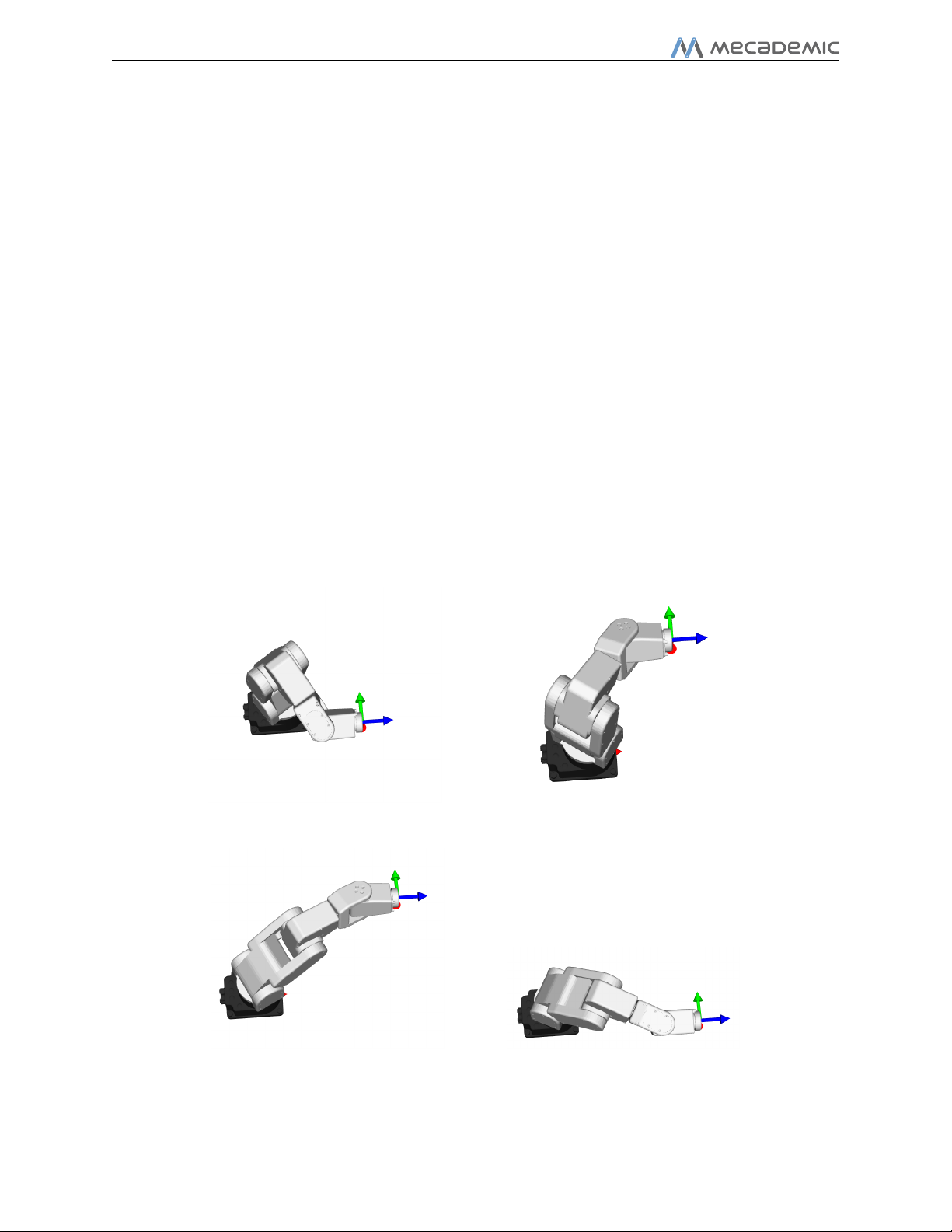
Figure 16 shows the result of each of the four MoveLin commands.
(a) MoveLin(140,-100,250,0,90,0) (b) MoveLin(140,100,250,0,90,0)
(c) MoveLin(270,100,250,0,90,0) (d) MoveLin(270,-100,250,0,90,0 )
Figure 16: The four separate robot positions that define the motion sequence
Page 22 of 25 Copyright
c
2017 by Mecademic Inc.

User Manual
9 Troubleshooting
No lights are on upon power up
• Make sure all connectors are properly attached.
• Make sure the AC outlet works (the green light on the power supply should be on).
No connection to the robot’s web interface
• Make sure the Ethernet cable is properly connected. The green Ethernet light should
pulse like on an RJ-45 connector. If the green LED is not illuminated, detach and
reconnect the Ethernet cable.
• Make sure the router/switch works by checking the lights of the connexion socket.
• Make sure you are connected to the same network as the robot.
• If you are using static IP addresses, make sure that the robot’s IP default address
(192.168.0.100) does not conflict with any other device on the network. For example:
Robot : I P = 192.168.0.100, netmask = 255.255.255.0, gateway = 192.168.0.1
Computer : IP = 192.168.0.101, netmask = 255.255.255.0, gateway = 192.168.0.1
• If you are using DHCP, make sure to verify the robot’s IP address through your router’s
web interface.
Robot fails to boot
• Disconnect the power supply from the AC outlet and wait for the green light of the
power supply to turn off. Then reconnect the power supply and boot the robot.
Robot’s IP address forgotten
• You can do a factory reset of the robot’s Ethernet configuration using the following
sequence, which takes approximately twenty seconds:
1. Press the Power button on the robot’s base continuously.
2. Hold the power button pressed until the Power, Home and Play LEDs, each flash
three times.
CAUTION:
B
Copyrightc 2017 by Mecademic Inc. Page 23 of 25
Never disassemble the robot. The robot requires no maintenance, and if you
think it is damaged, stop using it immediately and contact us.

User Manual
NOTICE:
If you are unable to solve your technical problem, do not hesitate to contact our
technical support team by email, at support@mecademic.com.
Whenever you contact our support team, please provide the serial number of your robot
and the sequence of numbers displayed after “Meca500” in the welcome message that appears
in the log panel upon connection with the robot: [3000][Connected to Meca500 x_x_x.x.x].
10 Storing the robot in its shipping box
To put the Meca500 back into the foam insert of its original shipping box, send the command
MoveJoints(0,-60,60,0,0,0) or jog the robot’s joints 1, 2 and 3 to 0◦, −60◦, and 60◦,
respectively. Recall that you must never force the brakes on joints 1, 2 and 3, unless there
is an emergency.
Page 24 of 25 Copyright
c
2017 by Mecademic Inc.

User Manual
11 EC Declaration of Incorporation (original)
According to the European Commission’s Machinery Directive 2006/42/EC, Annex II, Section 1B
The manufacturer Mecademic
1300 Saint-Patrick
Montreal, QC H3K 1A4
Canada
hereby declares that the product described below
Product designation: Extra-small six-axis industrial robot Meca500
Type: Meca500-R2
meets the applicable basic safety requirements of the Machinery Directive 2006/42/EC.
This partly completed machinery may not be put into operation until conformity of the
machine into which it will be incorporated is declared in conformity with the provisions of
the Machinery Directive 2006/42/EC, and with the regulations transposing it into national
law. Compliance with all essential requirements of Directive 2006/42/EC relies on the specific
robot installation and the final risk assessment.
The manufacturer agrees to forward on demand the relevant technical documentation,
compiled according to Directive 2006/42/EC, Annex VII, Part B, to state authorities.
Additionally the manufacturer declares the product in conformity with the following directives, according to which the product is CE marked:
• 2014/30/EU — Electromagnetic Compatibility Directive (EMC)
• 2011/65/EU — Restriction of the use of certain hazardous substances (RoHS)
Person responsible for the documentation: Dr. Ilian Bonev.
Montreal, QC, Canada Ilian Bonev, Eng., Ph.D.
March 21, 2017 Scientific Advisor
Copyrightc 2017 by Mecademic Inc. Page 25 of 25

Mecademic Inc.
1300 Saint-Patrick St
Montreal QC H3K 1A4
CANADA
 Loading...