


 Loading...

Universal Library
for
NI LabVIEW™
User’s Guide
Document Revision 9, March, 2007
Copyright 2007, Measurement Computing Corporation
Your new Measurement Computing product comes with a fantastic extra —
Management committed to your satisfaction!
Thank you for choosing a Measurement Computing product—and congratulations! You own the finest, and you can now enjoy the protection of the most comprehensive warranties and unmatched phone tech support. It’s the embodiment of our mission:
To provide data acquisition hardware and software that will save time and save money.
Simple installations minimize the time between setting up your system and actually making measurements. We offer quick and simple access to outstanding live FREE technical support to help integrate MCC products into a DAQ system.
Limited Lifetime Warranty: Most MCC products are covered by a limited lifetime warranty against defects in materials or workmanship for the life of the product, to the original purchaser, unless otherwise noted. Any products found to be defective in material or workmanship will be repaired, replaced with same or similar device, or refunded at MCC’s discretion. For specific information, please refer to the terms and conditions of sale.
Harsh Environment Program: Any Measurement Computing product that is damaged due to misuse, or any reason, may be eligible for replacement with the same or similar device for 50% of the current list price. I/O boards face some harsh environments, some harsher than the boards are designed to withstand. Contact MCC to determine your product’s eligibility for this program.
30 Day Money-Back Guarantee: Any Measurement Computing Corporation product may be returned within 30 days of purchase for a full refund of the price paid for the product being returned. If you are not satisfied, or chose the wrong product by mistake, you do not have to keep it.
These warranties are in lieu of all other warranties, expressed or implied, including any implied warranty of merchantability or fitness for a particular application. The remedies provided herein are the buyer’s sole and exclusive remedies. Neither Measurement Computing Corporation, nor its employees shall be liable for any direct or indirect, special, incidental or consequential damage arising from the use of its products, even if Measurement Computing Corporation has been notified in advance of the possibility of such damages.
Trademark and Copyright Information
Measurement Computing Corporation, InstaCal, Universal Library, and the Measurement Computing logo are either trademarks or registered trademarks of Measurement Computing Corporation. Refer to the Copyrights & Trademarks section on mccdaq.com/legal for more information about Measurement Computing trademarks. Other product and company names mentioned herein are trademarks or trade names of their respective companies.
© 200 Measurement Computing Corporation. All rights reserved. No part of this publication may be reproduced, stored in a
retrieval system, or transmitted, in any form by any means, electronic, mechanical, by photocopying, recording, or otherwise without the prior written permission of Measurement Computing Corporation.
Notice
Measurement Computing Corporation does not authorize any Measurement Computing Corporation product for use in life support systems and/or devices without prior written consent from Measurement Computing Corporation. Life support devices/systems are devices or systems that, a) are intended for surgical implantation into the body, or b) support or sustain life and whose failure to perform can be reasonably expected to result in injury. Measurement Computing Corporation products are not designed with the components required, and are not subject to the testing required to ensure a level of reliability suitable for the treatment and diagnosis of people.
3

Table of Contents
Introducing the Universal Library for LabVIEW™ ............................................ |
|
Installing and Configuring UL for LabVIEW...................................................... |
|
Installing the software ........................................................................................................................ |
|
Configuring your MCC hardware for use with UL for LabVIEW VIs ................................................... |
|
Overview of the Universal Library VIs ............................................................... |
|
Analog I/O VIs.................................................................................................................................... |
|
Signal conditioning VIs..................................................................................................................... |
|
Counter VIs...................................................................................................................................... |
1 |
Digital I/O VIs................................................................................................................................... |
1 |
Streamer file VIs .............................................................................................................................. |
1 |
Memory board VIs ........................................................................................................................... |
1 |
Miscellaneous VIs............................................................................................................................ |
1 |
How to use the LabVIEW Extensions (VIs) ..................................................... |
1 |
Using the Library with LabVIEW ...................................................................................................... |
1 |
UL function contexts: foreground (__Fg) and background (__Bg) ............................................... |
1 |
UL Extension VI example programs ................................................................................................ |
1 |
Universal Library Virtual Instruments (VIs)..................................................... |
1 |
Analog Input VIs .............................................................................................................................. |
1 |
AIn.VI ........................................................................................................................................... |
1 |
AInScBg.VI................................................................................................................................... |
|
AInScFg.VI................................................................................................................................... |
2 |
APretrBg.VI .................................................................................................................................. |
2 |
APretrFg.VI .................................................................................................................................. |
2 |
ATrigger.VI................................................................................................................................... |
2 |
ALoadQue.VI ............................................................................................................................... |
2 |
OptAIn.VI ..................................................................................................................................... |
|
SetTrig.VI ..................................................................................................................................... |
3 |
TIn.VI ........................................................................................................................................... |
3 |
TInScan.VI ................................................................................................................................... |
3 |
Analog Output VIs............................................................................................................................ |
3 |
AOut.VI ........................................................................................................................................ |
3 |
AOutScFg.VI ................................................................................................................................ |
|
AOutScBg.VI................................................................................................................................ |
4 |
Signal conditioning VIs..................................................................................................................... |
4 |
ACvtData.VI ................................................................................................................................. |
4 |
ACnvPrDt.VI................................................................................................................................. |
4 |
ACal.VI......................................................................................................................................... |
4 |
FromEng.VI.................................................................................................................................. |
4 |
ToEng.VI ...................................................................................................................................... |
4 |
ScaleArr.VI................................................................................................................................... |
4 |
ScalePnt.VI .................................................................................................................................. |
|
Counter VIs...................................................................................................................................... |
5 |
C8254Cfg.VI ................................................................................................................................ |
5 |
C7266Config.VI............................................................................................................................ |
5 |
C8536Cfg.VI ................................................................................................................................ |
5 |
C8536Init.VI ................................................................................................................................. |
5 |
C9513Config.VI............................................................................................................................ |
5 |
C9513Init.VI ................................................................................................................................. |
|
CFreqIn.VI.................................................................................................................................... |
6 |
CIn.VI ........................................................................................................................................... |
6 |
CIn32.VI ....................................................................................................................................... |
6 |
CLoad.VI ...................................................................................................................................... |
6 |
CLoad32.VI .................................................................................................................................. |
6 |
CStatus.VI.................................................................................................................................... |
6 |
CStore.VI ..................................................................................................................................... |
6 |
Digital I/O VIs................................................................................................................................... |
7 |
4

Universal Library for NI LabVIEW™ User's Guide
DBitIn.VI....................................................................................................................................... |
7 |
DBitOut.VI .................................................................................................................................... |
7 |
DCfgBit.VI .................................................................................................................................... |
7 |
DCfgPort.VI.................................................................................................................................. |
7 |
DIn.VI ........................................................................................................................................... |
7 |
DInScBg.VI .................................................................................................................................. |
7 |
DInScFg.VI................................................................................................................................... |
7 |
DOut.VI ........................................................................................................................................ |
|
DOutScBg.VI................................................................................................................................ |
8 |
DOutScFg.VI................................................................................................................................ |
8 |
Streamer File VIs ............................................................................................................................. |
8 |
FileAInScan.VI ............................................................................................................................. |
8 |
FileInfo.VI..................................................................................................................................... |
8 |
FilePret.VI .................................................................................................................................... |
8 |
FileRead.VI .................................................................................................................................. |
8 |
Memory board VIs ........................................................................................................................... |
|
MemRdPrt.VI................................................................................................................................ |
|
MemRead.VI ................................................................................................................................ |
9 |
MemReset.VI ............................................................................................................................... |
9 |
MemSetDT.VI............................................................................................................................... |
9 |
MemWrite.VI ................................................................................................................................ |
9 |
Serial VIs ......................................................................................................................................... |
9 |
RS485.VI...................................................................................................................................... |
9 |
Miscellaneous VIs............................................................................................................................ |
9 |
ErrHdlng.VI .................................................................................................................................. |
9 |
ErrMsg.VI ..................................................................................................................................... |
9 |
GetBoard.VI ................................................................................................................................. |
9 |
GetCfg.VI ..................................................................................................................................... |
9 |
GetStatus.VI............................................................................................................................... |
10 |
SelChan.VI................................................................................................................................. |
10 |
SetCfg.VI.................................................................................................................................... |
10 |
StopBg.VI................................................................................................................................... |
10 |
InByte.VI / InWord.VI.................................................................................................................. |
10 |
OutByte.VI / OutWord.VI ............................................................................................................ |
10 |
5

1
Introducing the Universal Library for LabVIEW™
With the Universal Library for LabVIEW (UL for LabVIEW) software, you can construct your own LabVIEW programs using UL Extension VIs with supported Measurement Computing’s data acquisition and control devices.
The UL for LabVIEW Extension VIs are supported with LabVIEW version 6 and greater.
The UL for LabVIEW includes a set of LabVIEW virtual instruments (VIs) that you use to construct your own programs in LabVIEW using Measurement Computing’s data acquisition and control boards. Each lowlevel VI corresponds to one UL function.
This manual details the syntax of each VI. Although the LabVIEW extensions closely follow the syntax of the UL, there are some differences. For information on the UL functions, refer to the Universal Library Function Reference (this manual is available on our web site at www.mccdaq.com/PDFmanuals/sm-ul-functions.pdf).
To use the UL with another language, refer to the Universal Library User's Guide (available on our web site at www.mccdaq.com/PDFmanuals/sm-ul-user-guide.pdf) and the Universal Library Function Reference (available on our web site at www.mccdaq.com/PDFmanuals/sm-ul-functions.pdf).
6

2
Installing and Configuring UL for LabVIEW
This chapter explains how to install the software on your computer, and how to configure the software for the boards that you will be using with it.
The UL for LabVIEW software contains the following components:
UL for LabVIEW rev. 7.11 software, which includes the UL Extension VIs
Sample programs for use with Extension VIs and MCC hardware
readme.txt
You can install this software on all operating systems that are supported by the UL and your version of LabVIEW.
Installing the software
The UL for LabVIEW software is installed from the Measurement Computing Data Acquisition Software CD.
Refer to the Quick Start Guide for instructions on installing the software on the Measurement Computing Data Acquisition Software CD. This booklet is available in PDF at www.mccdaq.com/PDFmanuals/DAQ- Software-Quick-Start.pdf.
Configuring your MCC hardware for use with UL for LabVIEW VIs
Before starting the LabVIEW environment, configure your Measurement Computing data acquisition board(s) using InstaCal. InstaCal stores all board-specific configuration information in a configuration file named CB.CFG. InstaCal creates and/or modifies the CB.CFG file when board configurations are added or updated.
The CB.CFG file is read by the UL. The LabVIEW Extension VIs use the CB.CFG file to access the hardware.
7

3
Overview of the Universal Library VIs
The Universal Library for LabVIEW contains a set of low-level VIs that you "wire" together to build your application. These VIs are grouped according to their purpose. All of the groups except for "Miscellaneous" are based on the type of devices they are used with.
Analog I/O VIs
The analog I/O VIs perform analog input and output and convert analog data. AIn.VI - Single analog input
Takes a single reading from an analog input channel (A/D). AInScBg.VI - Background analog input scan
Repeatedly scans a range of analog input (A/D) channels in the background. The channel range, the number of samples, the sampling rate, and the A/D range can all be specified. The collected data is stored in an array.
AInScFg.VI - Foreground analog input scan
Repeatedly scans a range of analog input (A/D) channels in the foreground. The channel range, the number of samples, the sampling rate, and the A/D range can all be specified. The data that is collected is stored in an array.
ALoadQue.VI - Load channel/gain queue
Loads a series of channel/gain pairs into A/D board's queue. These channel/gains will be used with all subsequent analog input VIs.
AOut.VI - Single analog output
Outputs a single value to an analog output (D/A). AOutScBg.VI - Background analog output scan
Repeatedly updates a range of analog output (D/A) channels in the background. The channel range, the number of samples, and the rate can all be specified. The data values from consecutive elements of an array are sent to each D/A channel in the scan.
AOutScFg.VI - Foreground analog output scan
Repeatedly updates a range of analog output (D/A) channels in the foreground. The channel range, the number of samples, and the rate can all be specified. The data values from consecutive elements of an array are sent to each D/A channel in the scan.
APretrBg.VI - Analog pre-triggered input in the background
Repeatedly scans a range of analog input (A/D) channels in the background while waiting for a trigger signal. When a trigger occurs, it returns the specified number of samples before and after the trigger occurred. The channel range, the sampling rate, and the A/D range can all be specified. The data that is collected is stored in an array.
APretrFg.VI - Analog pre-triggered input in the foreground
Repeatedly scans a range of analog input (A/D) channels in the foreground while waiting for a trigger signal. When a trigger occurs it returns the specified number of samples before and after the trigger occurred. The channel range, the sampling rate, and the A/D range can all be specified. The data that is collected is stored in an array.
ATrig.VI - Analog trigger
Reads the specified analog input until it goes above or below a specified threshold. When the trigger condition is met the current sample is returned.
8

Overview of the Universal Library VIs |
Signal conditioning VIs |
OptAIn.VI – Specifies analog input options.
Both AInScBg.VI and AInScFg.VI have an input called options which should be wired to this VIs output. It generates a value based on the Anded values of its inputs.
SetTrig.VI - Set the trigger source.
Configures the type and threshold value of external trigger signals. TIn.VI - Single temperature input
Reads a temperature input channel and, as necessary, filters it, performs cold junction compensation, and linearization.
TInScan.VI - Scans a range of thermocouple inputs.
Reads the temperature from a range of channels as described above. Returns the temperature values to an array.
Signal conditioning VIs
ACvtData.VI - Converts analog data
Each raw sample from an analog input is a 16-bit value. On some 12-bit A/D boards it consists of a 12-bit A/D value along with a four bit channel number. On 16-bit A/D boards it contains the 16-bit A/D value.
This conversion is done automatically by the AIn VI. It can also be done automatically by the AInScBg.VI or the AInScFg.VI with the CONVERTDATA option. In some cases though, it may be useful or necessary to collect the data and then do the conversion sometime later. The ACvtData.VI takes a buffer full of unconverted data and converts it.
ACnvPrDt.VI - Convert pre-trigger data
When data is collected by either APretrBg.VI or APretrFg.VI, the same conversion needs to be done as described above for ACvtData.VI.
However, both APretrBg.VI and APretrFg.VI collect analog data into an array. They treat the array like a circular buffer. While they are waiting for the trigger to occur, they fill the buffer. When the end of the buffer is reached, they return to the beginning of the buffer. When the trigger signal occurs, the VIs continue collecting data into the circular buffer until the requested number of samples have been collected.
When the data acquisition is complete, all of the data is in the array, but it is in the wrong order. The first element of the array does not contain the first data point. The data has to be rotated to the correct order.
This conversion can be done automatically by the APretrBg.VI or APretrFg.VI with the CONVERTDATA option. In some cases, though, it may be useful or necessary to collect the data and then do the conversion sometime later. The ACnvPrDt.VI takes a buffer full of unconverted data and converts it.
ACalData.VI - Calibrates raw data.
Calibrates raw data collected by cbAInScan() when the real-time software calibration is turned off. FromEng.VI - Convert to raw data.
Converts one data sample or an array of data samples from engineering units to raw data format. Can also convert a single voltage (or current) to a D/A count value for use as an analog trigger threshold value.
ToEng.VI - Convert to engineering units.
Converts one data sample or an array of data samples from raw data format to engineering units. ScalePnt.VI - Converts a raw data point to engineering units.
ScaleArray.VI - Converts raw data in an array to engineering units data in an array.
9

Overview of the Universal Library VIs |
Counter VIs |
Counter VIs
The counter VIs load, read, and configure counters. There are four types of counter chips used in Measurement Computing products - 8254s, 8536s, 7266s, and 9513s. Some of the counter commands only apply to one type of counter. To gain full access to the power of these counter VIs, you should refer to the data sheet for the type of counter you are using:
82C54 data sheet (available on our web site at www.mccdaq.com/PDFmanuals/82C54.pdf)
LS7266 data sheet (available on our web site at www.mccdaq.com/PDFmanuals/LS7266R1.pdf)
9513A data sheet (available on our web site at www.mccdaq.com/PDFmanuals/9513A.pdf)
C7266Config.VI – Configures an LS7266 counter.
Selects all of the programmable options that are associated with the LS7266 counter. C8254Cfg.VI - Configures an 8254 counter.
Selects the basic operating mode of an 8254 counter. C8536Cfg.VI - Sets the operating mode of an 8536 counter.
Sets all of the programmable options associated with an 8536 counter chip. C8536Ini.VI - Initializes an 8536 counter.
Initializes and selects all of the chip level features for an 8536 counter board. The options that are set by this command are associated with each counter chip, and not the individual counters within it.
C9513Cfg.VI - Sets the operating mode of a 9513 counter.
Sets all of the programmable options associated with a 9513 counter chip. It is similar in purpose to C8254Cfg.VI, except that it is used with a 9513 counter.
C9513Ini.VI - Initializes a 9513 counter.
Initializes and selects all of the chip level features for a 9513 counter board. The options that are set by this command are associated with the specified counter chip, and not the individual counters within it.
CFreqIn.VI - Measures the frequency of a signal.
Measures the frequency of a signal by counting it for a specified period of time (GatingInterval) and then converting the count to counts/sec (Hz). This VI only works with 9513 counters.
CIn.VI - Reads a counter.
Reads a counter’s current value and returns the value as a 16-bit integer. CIn32.VI - Reads a counter.
Reads a counter’s current value and returns the value as a 32-bit integer. CLoad.VI - Loads a counter.
Loads a counter with an initial 16-bit count value. CLoad32.VI - Loads a counter.
Loads a counter with an initial 32-bit count value. CStatus.VI – Gets a counter status.
Retrieves status information about a LS7266 based counter. This VI only works with LS7266 counters. CStore.VI - Stores the counter value when an interrupt occurs.
Installs an interrupt handler that stores the current count whenever an interrupt occurs. This VI only works with 9513 counters.
10
Overview of the Universal Library VIs |
Digital I/O VIs |
Digital I/O VIs
To gain full access to the power of these digital I/O VIs, you should refer to the data sheet for the type of digital interface you are using:
the 82C55 data sheet (available on our web site at www.mccdaq.com/PDFmanuals/82C55.pdf)
the 8536 data sheet (not available on our web site)
DBitIn.VI - Digital bit input.
Reads a single bit from a digital input port. DBitOut.VI - Digital bit output.
Sets a single bit on a digital output port.
DCfgBit.VI - Configures a specific digital bit within a digital port. Configures a specific bit within a digital port as an input or an output. DCfgPort.VI - Configures digital outputs.
Configures a digital port as an input or an output. DIn.VI - Digital input.
Reads a specified digital input port.
DInScBg.VI - Digital multiple byte or word input in the background.
Reads a specified number of bytes or words from a digital input port at a specified rate. DInScFg.VI - Digital multiple byte or word input in the foreground.
Reads a specified number of bytes or words from a digital input port at a specified rate. DOut.VI - Digital output.
Writes a byte or word to a digital output port.
DOutScBg.VI - Digital multiple byte or word output in the background. Writes a series of bytes or words to a digital output port at a specified rate. DOutScFg.VI - Digital multiple byte or word output in the foreground. Writes a series of bytes or words to a digital output port at a specified rate.
Streamer file VIs
These VIs create, fill, and read "streamer" files. These VIs also let you collect and store large amounts of analog input data. The amount of data is limited only by available disk space.
FileAInS.VI - Transfer analog input data directly to file.
Very similar to AInScFg.VI, except that data is stored in a file instead of an array. FilePret.VI - Pre-triggered analog input to a file.
Very similar to APretrFg.VI, except that data is stored in a file instead of an array. FileInfo.VI - Reads "streamer" file information.
Each streamer file contains information about how much data is in the file and the conditions under which it was collected (sampling rate, channels, etc.). This VI reads that information.
FileRead.VI - Reads data from a "streamer" file.
Reads a selected number of data points from a streamer file into an array.
11

Overview of the Universal Library VIs |
Memory board VIs |
Memory board VIs
The memory board VIs read from, write to, and control memory boards (MEGA-FIFO). The most common use for the memory boards is to store large amounts of data from an A/D board via a DT-Connect cable between the two boards. To do this, you should use the EXTMEMORY option with AInScBg.VI, AInScFg.VI, APretrBg.VI, or APretrFg.VI.
After data is transferred to the memory board, you can use the memory VIs to retrieve the data. MemSetDT.VI - Sets DT-Connect mode on a memory board
The memory boards have a DT-Connect interface which can be used to transfer data through a cable between two boards rather than through the PC's system memory. The DT-Connect port on the memory board can be configured as either an input (from an A/D) or as an output (to a D/A). This VI configures the port.
MemReset.VI - Resets the memory board address
The memory board is organized as a sequential device. When data is transferred to the memory board it is automatically put in the next address location. This VI resets the current address to the location 0.
MemRead.VI - Reads data from a memory board.
Reads a specified number of points from a memory board starting at a specified address. MemWrite.VI - Writes data to a memory board.
Writes a specified number of points to a memory board starting at a specified address. MemRdPrt.VI - Reads data collected with APretrBg.VI or APretrFg.VI.
Both APretrBg.VI and APretrFg.VI write the pre-triggered data to the memory board in a shifted order. This VI shifts the data and returns it in the correct order.
Miscellaneous VIs
These VIs perform error handling, configuration, and other miscellaneous operations. ErrHdlng.VI - Selects the type of error handling.
The Universal Library has a number of different methods of handling errors. This VI selects which of these methods will be used with all subsequent library calls. The options include stopping the program when an error occurs and printing error messages.
ErrMsg.VI - Returns an error message for a given error.
All library VIs return error codes. This VI converts an error code to an error message. GetBoard.VI - Get the board name.
Returns the name of the selected target board. GetCfg.VI - Get configuration options.
Extracts hardware configuration options from board configuration file. GetStatus.VI - Returns the status of background operations.
After a background operation is started your program will need to periodically check on its progress. This VI returns the current status of the process that is running.
InByte.VI - Read one byte.
Reads one byte of data from the specified port. InWord.VI - Read one word.
Reads one word of data from the specified port.
12

Overview of the Universal Library VIs |
Miscellaneous VIs |
OutByte.VI - Write one byte.
Writes one byte of data to the specified port. OutWord.VI - Write one word.
Writes one word of data to the specified port. SelChan.VI – Selects specific channel data from an array.
Allows one channel of data to be extracted from an array of interleaved data for multiple channels. SetCfg.VI - Set configuration options.
Sets hardware configuration options for a selected board. StopBg.VI - Stop a background process.
It is sometimes necessary to stop a background process in the case of an error or if the process has been set up to run continuously. This VI will stop a background process.
13
4
How to use the NI LabVIEW Extensions (VIs)
Using the Library with NI LabVIEW
The Universal Library NI LabVIEW extensions provide a complete set of virtual instruments (VIs) for interfacing all Measurement Computing data acquisition hardware. Each low-level VI corresponds to one Universal Library function. All of the VIs are combined into a LabVIEW Library named DAS16.LLB. There are two approaches you can use in developing new LabVIEW applications that can interface to Measurement Computing hardware.
Modify one of the example applications.
Build a new application from scratch using the low-level VIs supplied in the DAS16.LLB library.
The easiest way to get started is to modify one of the sample applications. Select an example application that contains the operating behavior you are looking for. The example applications contain the basic requirements for transferring data to and from the target hardware. Additional capability can be added by selecting new functions and placing them on the diagram window. The corresponding controls can then be selected and placed on the panel window. Wire the new functions to the existing application and test the program.
If you prefer to build an application from scratch, you can wire any LabVIEW functions together to build your application. When the application requires interaction with the data acquisition hardware, simply select the appropriate VI from the DAS16.LLB and add it to the working diagram.
To access the DAS16.LLB library VIs, do the following:
1.Make the Diagram window of the project the active window. If the Panel window is currently active, select the Show Diagram option from the Window menu.
2.From the Diagram window, select the Show Functions Palette option from the Window menu to open the
Functions palette.
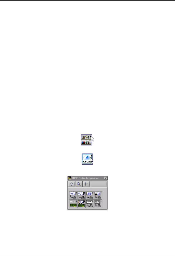
3.From the Functions palette, click on the User Libraries icon to open the User Libraries palette.
4.From the User Libraries palette, click on the MCC icon to open the MCC Data Acquisition palette.
5.Select the VI you want to use by clicking on the appropriate icon. Move the cursor back to the Diagram window and click to place the VI.
After placing the VIs you want to use on the Diagram window, you can wire them together. Save the application prior to testing. Refer to the documentation of each VI for specifics on the input and output parameters.
14
How to use the NI LabVIEW Extensions (VIs) |
UL Extension VI example programs |
UL function contexts: foreground (__Fg) and background (__Bg)
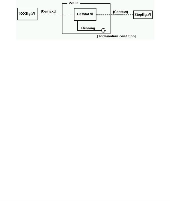
There are two distinct VIs for every UL function featuring background operation. One is for foreground operation only, and the other is for background operation only. The last two letters of the function names are "Fg" and "Bg" for foreground and background, respectively. Their parameter lists differ, in that background VIs have a Context output that must be wired to subsequent VIs (GetStatus.VI and StopBg.VI).
Context is an output data structure that contains information such as the board number, the data array, the size of the data array, the initial status of the operation, and the error code. Connecting a probe to the Context wire displays the elements in the data structure. You can check the intermediate values if desired. In general, the background VIs should conform to the wiring pattern shown in Figure 1. There are several example programs that effectively demonstrate the correct wiring and use of Contexts. Please refer to example VIs whose names end in "BG."
Figure 1. Background VIs General Wiring Pattern
UL Extension VI example programs
The UL for LabVIEW software package includes example programs which demonstrate how to use the Universal Library low-level extension VIs. We strongly suggest that you review the example programs to help you understand how to integrate the VIs into your program. The following example programs are included to demonstrate the LabVIEW interface:
Example |
VI explanation |
XAIN |
Single analog input in a while loop with a metered display. |
XAINSCBG |
Analog input scan in the background. Display data on a graph. Uses GetStatus.VI, |
|
StopBg.VI and OptAIn.VI. |
XAICNBG |
Analog input scan in the background in the CONTINUOUS mode. Same as |
|
XAINSCBG but runs continuously displaying data in real time. |
XAINSCFG |
Analog input scan in the foreground. Displays data on a graph. Uses SelChan.VI |
|
and OptAIn.VI. |
XAIOSCB |
Demonstrates concurrent analog input and output scans. |
XAOUT |
Single analog output. Demonstrates sequences, case statements, for loops, and |
|
while loops. |
XAOUTSCB |
Analog output scan in the background. Uses GetStatus.VI and StopBg.VI. |
XAOUTSCF |
Analog output scan in the foreground. Generates sinusoidal data. |
XAPRETRB |
Analog pre-trigger in the background. Display data on a graph. Uses GetStatus.VI, |
|
StopBg.VI and ACnvPrDt.VI. |
XAPRETRF |
Analog pre-trigger in the foreground. Displays data on a graph. Uses SelChan.VI |
|
and ACnvPrDt.VI. |
XASCFILE |
Analog input to a file. Displays data on a graph. Uses FileAInS.VI and |
|
FileRead.VI. |
XASCMEM |
Analog input to memory board. Displays data on a graph. Uses MemReset.VI and |
|
MemRead.VI. |
XCFREQ |
Displays frequency of signal at counter input. Uses C9513Init.VI and CFreqIn.VI. |
15

How to use the NI LabVIEW Extensions (VIs) UL Extension VI example programs
XCSTORE |
Stores counter values when interrupts occur and displays them. Uses CStore.VI, |
|
GetStatus.VI, and StopBg.VI. |
XCTR8254 |
Configures, loads and reads the counter. Displays the count. Uses C8254Cfg.VI, |
|
CLoad.VI, and CIn.VI. |
XCTR8536 |
Initializes, configures, loads, and reads the counter. Displays the count. Uses |
|
C8536Cfg.VI, CLoad.VI, and CIn.VI. |
XCTR9513 |
Initializes, configures, loads, and reads the counter. Displays the count. Uses |
|
C9513Cfg.VI, CLoad.VI, and CIn.VI. |
XCTR7266 |
Configures, loads, and reads the counter. Displays count and status. Uses |
|
C7266Cfg.VI, CLoad32.VI, CIn32.VI, and CStatus.VI. |
XDBITIN |
Configures and reads a digital bit. Toggles an LED accordingly. Uses DCfgPort.VI |
|
and DBitIn.VI. |
XDBITOUT |
Configures and writes a digital bit. Uses DCfgPort.VI and DBitOut.VI. |
XDIN |
Configures and reads a digital port. Toggles eight LEDs accordingly. Uses |
|
DCfgPort.VI and DIn.VI. |
XDCFGBIT |
Configures a bitwise configurable digital port. |
XDINSCBG |
Reads multiple bytes in the background. Uses DCfgPort.VI, DInScBg.VI, |
|
GetStatus.VI, and StopBg.VI. |
XDINSCFG |
Reads multiple digital bytes or words in the foreground. Uses DCfgPort.VI and |
|
DInScFg.VI. |
XDOUT |
Configures and writes to a digital port. Uses DCfgPort.VI and DOut.VI. |
XDOUTSCB |
Writes multiple digital bytes or words in the background. Uses DCfgPort.VI, |
|
DOutScBg.VI, GetStatus.VI, and StopBg.VI. |
XDOUTSCF |
Writes multiple digital bytes or words in the foreground. Uses DCfgPort.VI and |
|
DOutScFg.VI. |
XEVENTCTR |
Uses the event counters available from MCC's Personal Measurement Device™ |
|
and Measurement Advantage™ USB devices. Uses CIn32.VI. |
XTIN |
Single temperature input in a while loop with a metered display. Uses TIn VI. |
XTINSCAN |
Temperature input scan across multiple channels in a while loop. Data is displayed |
|
on a strip chart. Uses TInScan VI. |
16
5
Universal Library Virtual Instruments (VIs)
Analog Input VIs
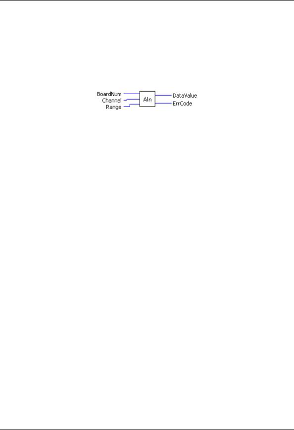
AIn.VI
Reads an A/D input channel. This VI reads the specified A/D channel from the specified board. If the A/D board has programmable gain, it sets the gain to the specified range. The raw A/D value is converted to an A/D value and returned to DataValue.
Summary:
Inputs: |
BoardNum [U32] - The board number when installed with InstaCal; can be 0 to |
|
100. |
|
Channel [I32] - A/D channel number |
|
Range [I32] - A/D Range |
Outputs: |
DataValue [U16] - Value of A/D sample |
|
ErrCode [I32] - Error code. See ErrMsg.VI on page 97. |
Arguments: |
|
BoardNum |
The board number associated with a board when it was installed with InstaCal. The |
|
specified board must have an A/D. BoardNum can be from 0 to 100. |
Channel |
The maximum allowable channel depends on which type of A/D board is being |
|
used. For boards that have both single ended and differential inputs, the maximum |
|
allowable channel number also depends on how the board is configured. For |
|
example, a PCI-DAS6025 has eight channels for differential, 16 for single-ended |
|
input mode. |
Range |
If the selected A/D board does not have a programmable gain feature, this |
|
argument is ignored. If the A/D board does have programmable gain, set the Range |
|
argument to the desired A/D range. |
|
The Range input values table on page 19 lists the constants you can use in the |
|
Range argument for most functions. Not all A/D boards support the same A/D |
|
ranges. Refer to the board’s hardware manual for a list of supported A/D ranges. |
17

|
Universal Library Virtual Instruments (VIs) |
|
|
Analog Input VIs |
|
|
|
|
|
Range input values |
|
|
|
|
Range |
Input value |
|
Range |
Input value |
|
|
|
|
|
|
|
|
|
±20 V |
27 |
|
0 to 5 V |
14 |
|
|
±10 V |
1 |
|
0 to 4 V |
36 |
|
|
±5 V |
2 |
|
0 to 2.5 V |
15 |
|
|
±4 V |
28 |
|
0 to 2 V |
16 |
|
|
±2.5 V |
3 |
|
0 to 1.67 V |
17 |
|
|
±2 V |
29 |
|
0 to 1.25 V |
18 |
|
|
±1.67 V |
4 |
|
0 to 1 V |
19 |
|
|
±1.25 V |
5 |
|
0 to 0.5 V |
32 |
|
|
±1 V |
6 |
|
0 to 0.25 V |
33 |
|
|
±0.625 V |
7 |
|
0 to 0.2 V |
34 |
|
|
±0.5 V |
8 |
|
0 to 0.1 V |
20 |
|
|
±0.25 V |
30 |
|
0 to 0.01 V |
21 |
|
|
±0.2 V |
31 |
|
0 to 0.02 V |
35 |
|
|
±0.1 V |
9 |
|
4 to 20 mA |
22 |
|
|
±0.05 V |
10 |
|
0 to 20 mA |
26 |
|
|
±0.01 V |
11 |
|
2 to 10 mA |
23 |
|
|
±0.005 V |
12 |
|
1 to 5 mA |
24 |
|
|
0 to 10 V |
13 |
|
0.5 to 2.5 mA |
25 |
|
DataValue |
Value of A/D measurement in binary counts. Use ToEng.VI (on page 48) to |
|
convert into engineering units (volts or milliamps). |
ErrCode |
Error code returned from the Universal Library. Zero if no error occurred. Use the |
|
ErrMsg VI (on page 97) to convert ErrCode into a readable string. |
18
Universal Library Virtual Instruments (VIs) |
Analog Input VIs |
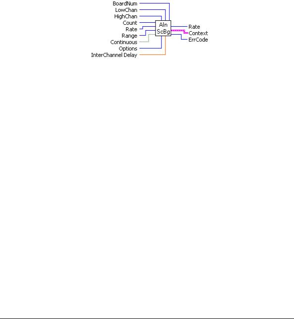
AInScBg.VI
Changed R3.3 ID, R5.4 ID'
Scans a range of A/D channels in the background and stores the samples in an array. This VI reads the specified number of A/D samples at the specified sampling rate from the specified range of A/D channels from the specified board. If the A/D board has programmable gain, it sets the gain to the specified range. The collected data is returned to the data array. This VI immediately returns control to your program and the data transfer from the A/D board into ADData will continue in the background. ADData is the array contained in the context output. Use the GetStatus.VI to check on the status of the background operation and to get data as it is being collected. Use StopBg.VI to terminate the background process before it has completed. Always execute StopBg.VI after any background operation has terminated normally to clear variables and flags.
Revision 3.3: added an option to disable real-time calibration. See OptAIn.VI on page 30 for details. Revision 5.4: added InterChannel Delay input.
Summary:
Inputs: |
BoardNum [U32] - The board number assigned when installed with InstaCal. Can |
|
be 0 to 100. |
|
LowChan [I32] - First A/D channel of scan |
|
HighChan [I32] - Last A/D channel of scan |
|
Count [I32] - Number of A/D samples to collect |
|
Rate [I32]- Sample rate in scans per second |
|
Range [I32]- A/D range code |
|
Continuous [TF] - Run the VI in an endless loop |
|
Options [I32] - Bit fields that control various options. |
|
InterChannel Delay [SGL] - Delay in seconds between channels in a scan. |
Outputs: |
Rate [I32] - Actual rate the board sampled |
|
Context [cluster] - Output data structure. |
|
ErrCode [I32] - Error code. See ErrMsg.VI on page 97. |
Arguments: |
|
BoardNum |
The board number associated with a board when it was installed with InstaCal. The |
|
specified board must have an A/D. Can be from 0 to 100. |
LowChan |
First A/D channel of scan. |
HighChan |
Last A/D channel of scan. |
|
Low/High Channel #: The maximum allowable channel depends on which type of |
|
A/D board is being used. For boards that have both single-ended and differential |
|
inputs, the maximum allowable channel number also depends on how the board is |
|
configured. For example, a PCI-DAS6025 has 8 channels for differential, 16 for |
|
single-ended mode. |
Count |
Specifies the total number of A/D samples that will be collected. If more than one |
|
channel is being sampled then the number of samples collected per channel is |
|
equal to Count / (HighChan- LowChan+1). |
19

Universal Library Virtual Instruments (VIs) Analog Input VIs
Rate (input) |
This is the rate at which scans are triggered. If you are sampling four channels, 0-3, |
|
specifying a rate of 10,000 scans per second (10 kS/s) will result in the A/D |
|
converter rate of 40 kS/s: (4 channels at 10,000 samples per channel per second). |
|
This is different from some software where you specify the total A/D chip rate. In |
|
those systems, the per channel rate is equal to the A/D rate divided by the number |
|
of channels in a scan. This argument also returns the value of the actual rate set. |
|
This may be different from the requested rate because of pacer limitations. |
Caution! You will generate an error if you specify a total A/D rate beyond the capability of the board. For example; if you specify LowChan = 0, HighChan = 7 (8 channels total) and Rate = 40,000 and you are using a PCI-DAS6025, you will get an error. You have specified a total rate of 8 x 40,000 = 320,000.
The PCI-DAS6025 is capable of converting 200,000 samples per second. The maximum sampling rate depends on the A/D board that is being used and on the sampling mode options.
Range |
If the selected A/D board does not have a programmable range feature, this |
|
|
argument is ignored. Otherwise the gain can be set to any of the following ranges |
|
|
that are supported by the selected A/D board. Refer to the board-specific |
|
|
information for the list of ranges supported by each board. See the "Range input |
|
|
values" table on page 19 for valid values. Refer to board-specific information |
|
|
contained in the Universal Library User's Guide (available at |
|
|
www.mccdaq.com/PDFmanuals/sm-ul-user-guide.pdf) for a list of the A/D ranges |
|
|
supported by each board. |
|
Continuous |
This option (True) puts the VI in an endless loop. After it collects the required |
|
|
number of samples, it resets to the start of the buffer and begins again. The only |
|
|
way to stop this operation is with StopBg.VI. |
|
Options |
For a detailed explanation of the Options field, refer to OptAIn.VI on page 30. The |
|
|
OptAIn.VI must be wired to this input. |
|
InterChannel Delay |
Delay in seconds between channels in a scan. Negative values indicate that the |
|
|
interchannel delay will automatically be minimized. Currently, positive values will |
|
|
result in interchannel delays corresponding to the Rate sampling rate. For example: |
|
|
1/(Rate*(HighChan-LowChan+1)). |
|
Rate (output) |
Actual sampling rate in channel scans per second. This may be different from the |
|
|
requested rate because of pacer limitations. |
|
Context |
Data structure containing information from a background operation. Some of the |
|
|
information included is the board number, the data array, the array size, and the |
|
|
initial status of the background operation. |
|
|
Follow the steps below when wiring this VI: |
|
|
1. |
Start a background operation. |
|
2. |
GetStatus.VI checks for completion (boolean output called |
|
3. |
"Running"). |
|
StopBg.VI terminates the operation, if not already done, and |
|
|
|
frees memory aliases. |
|
4. |
Data output from the background operation is passed to |
|
|
GetStatus.VI and StopBg.VI via "Context", and can be wired |
|
|
from one or both of them for intermediate or final actions, |
|
|
respectively. |
|
The demo VIs illustrate this process effectively. |
|
ErrCode |
Error code returned from the Universal Library. Zero if no error occurred. Use the |
|
|
ErrMsg VI to convert ErrCode into a readable string. |
|
Important - Read board-specific information in UL User's Guide
In order to understand the functions, read the board-specific information contained in the Universal Library User's Guide (available on our web site at www.mccdaq.com/PDFmanuals/sm-ul-user-guide.pdf). The example programs should be examined and run prior to attempting any programming of your own.
20
Universal Library Virtual Instruments (VIs) |
Analog Input VIs |
AInScFg.VI
Changed R3.3 ID, R5.4 ID
Scans a range of A/D channels in the foreground and stores the samples in an array. This VI reads the specified number of A/D samples at the specified sampling rate from the specified range of A/D channels from the specified board. If the A/D board has programmable gain, it sets the gain to the specified range. The collected data is returned to the data array. This VI will not return control to your program until all requested data has been collected and returned to ADData.
Revision 3.3: added an option to disable real-time calibration. See OptAIn.VI on page 30 for details. Revision 5.4: added InterChannel Delay input.
Summary:
Inputs: |
BoardNum [U32] - The board number assigned when installed with InstaCal. Can |
|
be 0 to 100. |
|
LowChan [I32] - First A/D channel of scan |
|
HighChan [I32] - Last A/D channel of scan |
|
Count [I32] - Number of A/D samples to collect |
|
Rate [I32] - Sample rate in scans per second |
|
Range [I32] - A/D range code |
|
Options [I32] - Bit fields that control various options. See Note 1. |
|
InterChannel Delay [SGL]- Delay in seconds between channels in a scan. |
Outputs: |
Rate [I32] - Actual rate the board sampled |
|
ADData [U16] - Data array that stores A/D values |
|
ErrCode [I32] - Error code. See ErrMsg.VI on page 97. |
Arguments: |
|
BoardNum |
The board number associated with a board when it was installed with InstaCal. The |
|
specified board must have an A/D. |
LowChan |
First A/D channel of scan. |
HighChan |
Last A/D channel of scan. |
|
Low/High Channel #: The maximum allowable channel depends on which type of |
|
A/D board is being used. For boards that have both single-ended and differential |
|
inputs, the maximum allowable channel number also depends on how the board is |
|
configured. For example, a PCI-DAS6025 has 8 channels for differential, 16 for |
|
single-ended mode. |
Count |
Specifies the total number of A/D samples that will be collected. If more than one |
|
channel is being sampled then the number of samples collected per channel is |
|
equal to Count / (HighChanLowChan+1). |
Rate |
This is the rate at which scans are triggered. If you are sampling four channels, 0-3, |
|
then specifying a rate of 10,000 scans per second (10 kS/s) will result in the A/D |
|
converter rate of 40 kS/s: (4 channels at 10,000 samples per channel per second). |
|
This is different from some software where you specify the total A/D chip rate. In |
|
those systems, the per channel rate is equal to the A/D rate divided by the number |
|
of channels in a scan. This argument also returns the value of the actual rate set. |
|
This may be different from the requested rate because of pacer limitations. |
21

Universal Library Virtual Instruments (VIs) |
Analog Input VIs |
Caution! You will generate an error if you specify a total A/D rate beyond the capability of the board. For example, if you specify LowChan = 0, HighChan = 7
(8 channels total) and Rate = 40,000 and you are using a PCI-DAS6025, you will get an error. You have specified a total rate of 8 x 40,000 = 320,000. The PCI-DAS6025 is capable of converting 200,000 samples per second. The maximum sampling rate depends on the A/D board that is being used. It is also dependent on the sampling mode options.
Range |
If the selected A/D board does not have a programmable range feature, then this |
|
argument will be ignored. Otherwise the gain can be set to any of the following |
|
ranges that are supported by the selected A/D board. Refer to board-specific |
|
information for the list of ranges supported by each board. See the "Range input |
|
values" table on page 19 for valid values. |
|
Refer to board-specific information contained in the Universal Library User's |
|
Guide (available on our web site at www.mccdaq.com/PDFmanuals/sm-ul-user- |
|
guide.pdf) for a list of the A/D ranges supported by each board. |
Options |
For a detailed explanation of the Options field refer to OptAIn.VI on page 30. |
|
The OptAIn.VI must be wired to this input. |
InterChannel Delay |
Delay in seconds between channels in a scan. Negative values indicate that the |
|
interchannel delay will automatically be minimized. Currently, positive values will |
|
result in interchannel delays corresponding to the Rate sampling rate. For example: |
|
1/(Rate*(HighChan-LowChan+1)). |
ErrCode |
Error code returned from the Universal Library. Zero if no error occurred. Use the |
|
ErrMsg VI to convert ErrCode into a readable string. |
Important - Read board-specific information in UL User's Guide
In order to understand the functions, read the board-specific information contained in the Universal Library User's Guide (available on our web site at www.mccdaq.com/PDFmanuals/sm-ul-user-guide.pdf). The example programs should be examined and run prior to attempting any programming of your own.
22
Universal Library Virtual Instruments (VIs) |
Analog Input VIs |
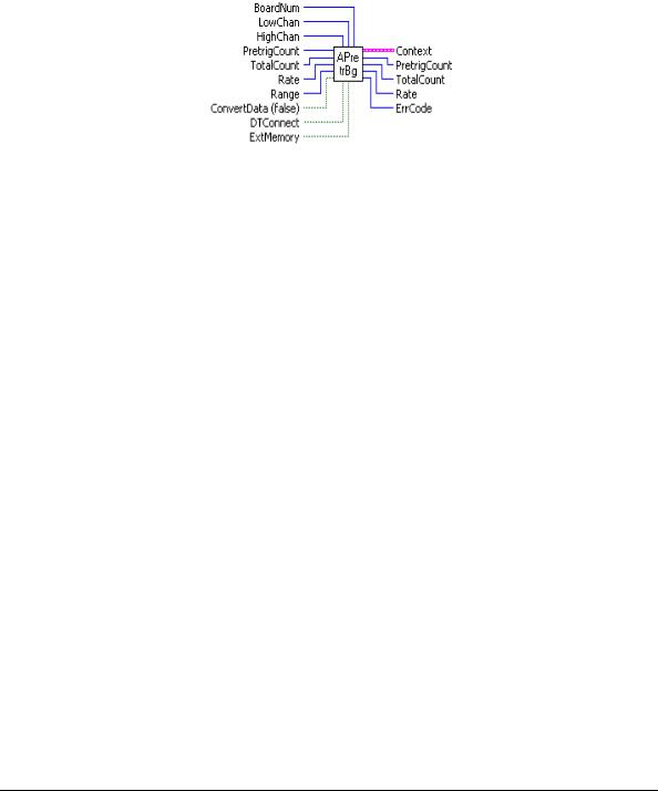
APretrBg.VI
Waits for a trigger to occur and then returns a specified number of analog samples before and after the trigger occurred. If only 'polled gate' triggering is supported, the trigger input line (see board user's manual) must be at TTL low before this VI is called or a TRIGSTATE error will occur. The trigger occurs when the trigger condition is met. See SetTrig.VI and board-specific information. After this VI is called, execution will return immediately to the next point in your program and the data collection —from the A/D into the Data portion of the Context cluster—will continue in the background. Use GetStatus.VI to check on the status of the background operation. Use StopBg.VI to terminate the background process before or after it has completed its function.
Summary:
Inputs: |
BoardNum [U32] - The board number assigned when installed with InstaCal. Can |
|
be 0 to 100. |
|
LowChan [I32] - First A/D channel of scan |
|
HighChan [I32] - Last A/D channel of scan |
|
PretrigCount [I32] - Number of pre-trigger A/D samples to collect |
|
TotalCount [I32] - Total number of A/D samples to collect |
|
Rate [I32] - Sample rate in scans per second |
|
Range [I32] - A/D Range code or 0 |
|
ConvertData [TF] - Convert data option (Boolean) |
|
DTConnect [TF] - DT connect option (Boolean) |
|
ExtMemory [TF] - External memory option (Boolean) |
Outputs: |
Context [cluster] - Output data structure. |
|
PretrigCount [I32] - Number of pre-trigger A/D samples collected |
|
TotalCount [I32] - Total number of A/D samples collected |
|
Rate [U32] - Actual sample rate in scans per second |
|
ErrCode [I32] - Error code. See ErrMsg.VI on page 97. |
Arguments: |
|
BoardNum |
The board number associated with a board when it was installed with InstaCal. The |
|
specified board must have an A/D. |
LowChan |
First A/D channel of scan. |
HighChan |
Last A/D channel of scan. |
|
Low/High Channel #: The maximum allowable channel depends on which type of |
|
A/D board is being used. For boards that have both single-ended and differential |
|
inputs, the maximum allowable channel number also depends on how the board is |
|
configured. For example, a PCI-DAS6025 has 8 channels for differential, 16 for |
|
single-ended mode. |
23

Universal Library Virtual Instruments (VIs) Analog Input VIs
PretrigCount |
Specifies the number of samples before the trigger that will be returned. |
|
|
PretrigCount must be less than TotalCount - 512. If the trigger occurs too early, |
|
|
then fewer than the requested number of pre-trigger samples will be collected. In |
|
|
that case a TOOFEW error will occur. The PretrigCount will be set to indicate how |
|
|
many pretrigger samples were collected and the post-trigger samples will still be |
|
|
collected. |
|
TotalCount |
Specifies the total number of samples that will be collected and stored in |
|
|
DataArray. TotalCount must be greater than or equal to PretrigCount + 512. If the |
|
|
trigger occurs too early, then fewer than the requested number of samples will be |
|
|
collected. In that case a TOOFEW error will occur. The TotalCount will be set to |
|
|
indicate how many total samples were actually collected. |
|
Rate |
Desired sample rate in samples per channel per second. |
|
Range |
If the selected A/D board does not have a programmable gain feature, this |
|
|
argument will be ignored. Otherwise the Range can be set to any of the ranges that |
|
|
are supported by the selected A/D board. See the "Range input values" table on |
|
|
page 19 for valid values. |
|
|
Refer to board-specific information contained in the Universal Library User's |
|
|
Guide (available on our web site at www.mccdaq.com/PDFmanuals/sm-ul-user- |
|
|
guide.pdf) for a list of the A/D ranges supported by each board. |
|
ConvertData |
Set this option to False (default) when using APretrBg.VI. |
|
DTConnect |
When the DTCONNECT option (True) is used with this VI, the data from ALL |
|
|
A/D conversions is sent out the DT-CONNECT interface. While this VI is waiting |
|
|
for a trigger to occur, it will send data out the DT-CONNECT interface |
|
|
continuously. If you have a MCC memory board plugged into the DT-CONNECT |
|
|
interface then you should use EXTMEMORY option rather than this option. |
|
ExtMemory |
If you use this option (True) to send the data to a connected memory board then |
|
|
you must use MemRdPrt.VI to later read the pre-trigger data from the memory |
|
|
board. If you use MemRead.VI, the data will NOT be in the correct order. Every |
|
|
time this option is used it will overwrite any data that is already stored in the |
|
|
memory board. Read all data from the board (with MemRdPrt.VI) before |
|
|
collecting any new data. The Mega Fifo memory must be fully populated to use the |
|
|
APretrBg.VI or APretrFg.VI. |
|
Context |
The data array for the pretrigger data. This is a data structure containing output |
|
|
information including the board number, the contents of DataArray, the size of |
|
|
DataArray, and the initial status of the background operation. CONTEXT must be |
|
|
wired to subsequent VIs in order to process this VI correctly. |
|
|
Follow the steps below when wiring this VI: |
|
|
1. |
Start a background operation. |
|
2. |
GetStatus.VI checks for completion (boolean output called "Running"). |
|
3. |
StopBg.VI terminates the operation, if not already done, and frees memory aliases. |
|
4. |
Data output from the background operation is passed to GetStatus.VI and StopBg.VI |
|
|
via Context, and can be wired from one or both of them for intermediate or final |
|
|
actions, respectively. |
|
The demo VIs illustrate this process effectively. |
|
PretrigCount |
Actual number of pre-trigger A/D samples collected. |
|
TotalCount |
Total number of A/D samples collected. |
|
Rate |
Actual sample rate in scans per second . |
|
ErrCode |
Error code returned from the Universal Library. Zero if no error occurred. Use the |
|
|
ErrMsg VI to convert ErrCode into a readable string. |
|
24
Universal Library Virtual Instruments (VIs) |
Analog Input VIs |
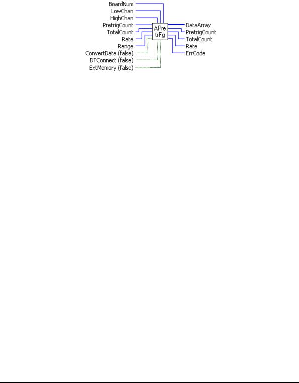
APretrFg.VI
Waits for a trigger to occur and then returns a specified number of analog samples before and after the trigger occurred. If only 'polled gate' triggering is supported, the trigger input line (refer to the hardware user's manual) must be at TTL low before this VI is called or a TRIGSTATE error will occur. The trigger occurs when the trigger condition is met. See SetTrig.VI on page 33 and board-specific information for details. This VI will not return to your program until all of the requested data has been collected and returned to DataArray.
Summary:
Inputs: |
BoardNum [U32] - The board number assigned when installed with InstaCal. Can |
|
be 0 to 100. |
|
LowChan [I32] - First A/D channel of scan |
|
HighChan [I32] - Last A/D channel of scan |
|
PretrigCount [I32] - Number of pre-trigger A/D samples to collect |
|
TotalCount [I32] - Total number of A/D samples to collect |
|
Rate [U32] - Sample rate in scans per second |
|
Range [I32] - A/D range code or 0 |
|
ConvertData [TF] - Convert data option (Boolean) |
|
DTConnect [TF] - DT connect option (Boolean) |
|
ExtMemory [TF] - External memory option (Boolean) |
Outputs: |
DataArray [U32] - Data array that stores A/D values |
|
PretrigCount [I32]- Actual number of pre-trigger A/D samples collected |
|
TotalCount [I32] - Total number of A/D samples collected |
|
Rate [U32] - Actual sample rate in scans per second |
|
ErrCode [I32] - Error code. See ErrMsg.VI |
Arguments: |
|
BoardNum |
The board number associated with a board when it was installed with InstaCal. The |
|
specified board must have an A/D. |
LowChan/HighChan |
The maximum allowable channel depends on which type of A/D board is being |
|
used. For boards that have both single ended and differential inputs, the maximum |
|
allowable channel number also depends on how the board is configured (8 |
|
channels for differential, 16 for single-ended). |
PretrigCount |
Specifies the number of samples before the trigger that will be returned. |
|
PretrigCount must be less than TotalCount - 512. If the trigger occurs too early, |
|
fewer than the requested number of pre-trigger samples will be collected. In that |
|
case a TOOFEW error will occur. The PretrigCount will be set to indicate how many |
|
samples were collected and the post trigger samples will still be collected. |
TotalCount |
The total number of samples that will be collected and stored in DataArray. |
|
TotalCount must be greater than or equal to PretrigCount + 512. If the trigger |
|
occurs too early then fewer than the requested number of samples will be collected. |
|
In that case, a TOOFEW error will occur. The TotalCount will be set to indicate how |
|
many samples were actually collected. |
25

Universal Library Virtual Instruments (VIs) Analog Input VIs
Range |
If the selected A/D board does not have a programmable gain feature, this |
|
argument is ignored. Otherwise the Range can be set to any of the ranges that are |
|
supported by the selected A/D board. See the "Range input values" table on page |
|
19 for valid values. |
|
Refer to board-specific information contained in the Universal Library User's |
|
Guide (available on our web site at www.mccdaq.com/PDFmanuals/sm-ul-user- |
|
guide.pdf) for a list of the A/D ranges supported by each board. |
ConvertData |
The data is collected into a "circular" buffer. When the data collection is complete, |
|
the data is in the wrong order. If using the CONVERTDATA option (True), when |
|
data acquisition is complete, the data is automatically rotated into the correct order |
|
and converted to 12-bit values. Otherwise, you must call ACnvPrDt.VI to rotate |
|
the data. |
DTConnect |
When the DTConnect option (True) is used with this VI, the data from all A/D |
|
conversions is sent out the DT-CONNECT interface. While this VI is waiting for a |
|
trigger to occur, it will send data out the DT-CONNECT interface continuously. If |
|
you have a memory board plugged into the DT-CONNECT interface, use the |
|
ExtMemory option rather than this option. |
ExtMemory |
If using this option (True) to send the data to a connected memory board, you must |
|
use MemRdPrt.VI to read the pre-trigger data from the memory board later. If you |
|
use the MemRead.VI, the data will not be in the correct order. Every time this |
|
option is used it will overwrite any data that is already stored in the memory board. |
|
All data should be read from the board (with MemRdPrt.VI before collecting any |
|
new data. The Mega-Fifo memory must be fully populated to use the APretrBg.VI |
|
or APretrFg.VI. |
DataArray |
The data array for the pretrigger data. |
PretrigCount [ |
Actual number of pre-trigger A/D samples collected. |
TotalCount |
Total number of A/D samples collected. |
Rate |
Actual sample rate in scans per second. |
ErrCode |
Error code returned from the Universal Library. Zero if no error occurred. Use the |
|
ErrMsg VI to convert ErrCode into a readable string. |
26
Universal Library Virtual Instruments (VIs) |
Analog Input VIs |
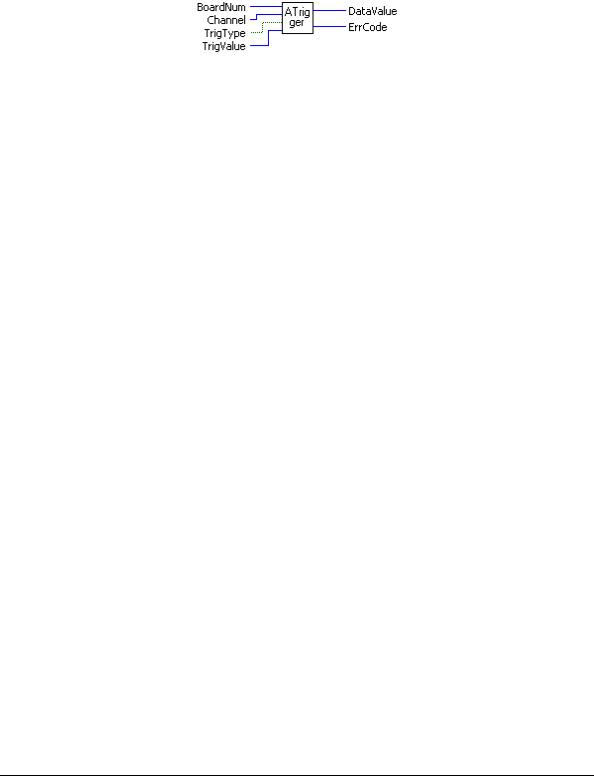
ATrigger.VI
Waits for a specified analog input channel to go above or below a specified value. This VI continuously reads the specified channel and compares its value to TrigValue. Depending on whether TrigType is ABOVE or BELOW it waits for the first A/D sample that is above or below TrigValue. It returns the first sample that meets the trigger criteria to DataValue.
Summary:
Inputs: |
BoardNum [U32] - The board number assigned when installed with InstaCal. Can |
|
be 0 to 100. |
|
Channel [I32] - A/D channel number |
|
TrigType [TF] - TRIGABOVE (True) or TRIGBELOW (False) - Specifies whether to wait |
|
for the analog input to be above or below the specified trigger value. |
|
TrigValue [I32] - The threshold value that all A/D values are compared to |
Outputs: |
DataValue [U16] - The value of the first A/D sample that met the trigger criteria is |
|
returned here. |
|
ErrCode [I32] - Error code. See ErrMsg.VI |
Arguments: |
|
BoardNum |
The board number associated with a board when it was installed with InstaCal. The |
|
specified board must have an A/D. |
Channel |
The maximum allowable channel depends on which type of A/D board is being |
|
used. For boards that have both single ended and differential inputs, the maximum |
|
allowable channel number also depends on how the board is configured. For |
|
example, a PCI-DAS6025 has 8 channels for differential, 16 for single-ended. |
TrigType |
Specifies whether to wait for the analog input to be ABOVE or BELOW the |
|
specified trigger value. |
|
TRIGABOVE - Wait for analog input to be above the specified trigger value. |
|
TRIGBELOW - Wait for analog input to be below the specified trigger value. |
TrigValue |
Must be in the range 0 to 4095 for 12-bit A/D boards, or 0 to 65,535 for 16-bit |
|
A/D boards. |
|
Use this VI with caution in Windows programs. All active windows will be locked |
|
on the screen until the trigger condition is satisfied. All keyboard and mouse |
|
actions will also be locked until the trigger condition is satisfied. |
DataValue |
First sample that meets trigger criteria. Use ToEng.VI to convert from binary |
|
counts to engineering units (volts or milliamps). |
ErrCode |
Error code returned from the Universal Library. Zero if no error occurred. Use the |
|
ErrMsg VI to convert ErrCode into a readable string. |
27

Universal Library Virtual Instruments (VIs) |
Analog Input VIs |
ALoadQue.VI
Loads the A/D board's channel/gain queue. This VI only works with A/D boards that have channel/gain queue hardware.
Summary:
Inputs: |
BoardNum [U32] - The board number assigned when installed with InstaCal. Can |
|
be 0 to 100. |
|
ChanArray [I16] - Array containing channel values |
|
GainArray [I16] - Array containing A/D range values |
|
Count [I32] - Number of elements in ChanArray and GainArray, or (0) to disable |
|
the board's channel/gain queue. |
Outputs: |
ErrCode [I32] - Error code. See ErrMsg.VI |
Arguments: |
|
BoardNum |
The board number associated with a board when it was installed. The specified |
|
board must have an A/D and a channel/gain queue. |
ChanArray |
This array should contain all of the channels that will be loaded into the channel |
|
gain queue. |
GainArray |
This array should contain each of the A/D ranges that will be loaded into the |
|
channel gain queue. |
Count |
Specifies the total number of channel/gain pairs that will be loaded into the queue. |
|
ChanArray and GainArray should contain at least Count elements. Set Count=0 to |
|
disable the board's channel/gain queue. The maximum value is specific to the |
|
queue size of the A/D boards channel gain queue. |
|
Normally the AInScBg.VI or AInScFg.VI scans a fixed range of channels (from |
|
LowChan to HighChan) at a fixed A/D range. If you load the channel gain queue |
|
with this VI, all subsequent calls to AInScFg.VI or AInScBg.VI cycle through the |
|
channel/gain pairs that you have loaded into the queue. |
ErrCode |
Error code returned from the Universal Library. Zero if no error occurred. Use the |
|
ErrMsg VI to convert ErrCode into a readable string. |
28
Universal Library Virtual Instruments (VIs) |
Analog Input VIs |
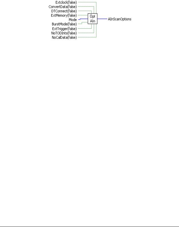
OptAIn.VI
Changed R3.3ID
Generates option input for AInScBg.VI or AInScFg.VI.
Rev.3.3: Added NoCalibrateData option.
Rev. 7.1: Added BurstIO setting for Mode option
Summary:
Inputs: |
ExtClock [TF] - External (True) or internal clock (False = "TIMED") |
|
ConvertData [TF] - Separate data and channel tags (True). |
|
(False = NOCONVERTDATA") |
|
DTConnect [TF] - DT connect option (True). (False = "NODTCONNECT") |
|
ExtMemory [TF] - External memory option (Mega Fifo board) (True). |
|
False= "NORMMEMORY") |
|
Mode [I32] - Sampling mode used. |
|
BurstMode [TF] - Burst mode option (board-specific) (True). (False = |
|
"NOBURSTMODE") |
|
ExtTrigger [TF] - External trigger option (True). (False = "NOEXTRIGGER") |
|
NoToDints [TF] - Option to disable time of day interrupts (True). |
|
(False = "TODInts") |
|
NoCalData [TF] - Option to disable real time software calibration (True). |
Output: |
(False = "CalData") |
AInScanOptions [I32] - Anded value of input options. |
|
Arguments: |
|
ExtClock |
If this option is used, then conversions will be controlled by the signal on the |
|
trigger input line rather than by the internal pacer clock. Each conversion will be |
|
triggered on the appropriate edge of the trigger input signal (refer to board-specific |
|
information). When this option is used, the Rate argument is ignored. The |
|
sampling rate is dependent on the trigger signal. Options for the board will default |
|
to a transfer mode that will allow the maximum conversion rate to be attained |
|
unless otherwise specified. |
ConvertData |
If the CONVERTDATA option is used for 12-bit boards, then the data that is |
|
returned to data buffer (array) will automatically be converted to 12-bit A/D |
|
values. If NOCONVERTDATA is used, data from 12-bit A/D boards will be returned as |
|
16-bit values that will contain both a 12-bit A/D value and a 4-bit channel number. |
|
After the data collection is complete, you can call ACvtData.VI to convert the data |
|
after the fact. CONVERTDATA cannot be specified if you are using a background |
|
VI and DMA transfers. This option is ignored for 16-bit boards. |
DTConnect |
All A/D values will be sent to the A/D board's DT CONNECT port. This option is |
|
incorporated into the EXTMEMORY option. Use DTCONNECT only when the |
|
external board is not supported by the Universal Library. |
29

Universal Library Virtual Instruments (VIs) Analog Input VIs
ExtMemory |
Data is returned to a data buffer (array). EXTMEMORY causes the command to |
||
|
send the data to a connected memory board via the DT-Connect interface rather |
||
|
than returning the data to data buffer (array). Every time this option is used it |
||
|
overwrites any data already stored in the memory board. The data should be |
||
|
unloaded with the MemRead.VI before collecting new data. |
||
|
Do not use EXTMEMORY and DTCONNECT together. |
||
Mode |
Trigger and transfer method options |
||
|
|
|
|
|
Mode |
Setting |
Explanation |
|
|
|
|
|
DEFAULTIO |
0 |
Default and recommended sampling mode. The optimum |
|
|
|
sampling mode is chosen based on board type and sampling |
|
|
|
speed. |
|
SINGLEIO |
1 |
A/D conversions and transfers to memory are initiated by an |
|
|
|
interrupt. One interrupt per conversion. |
|
DMAIO |
2 |
A/D conversions are initiated by a trigger. Transfers are |
|
|
|
initiated by a DMA request. |
|
BLOCKIO |
3 |
A/D conversions are initiated by a trigger. Transfers are |
|
|
|
handled by REP-INSW. |
|
BURSTIO |
4 |
Allows higher sampling rates for sample counts up to full |
|
|
|
FIFO. Data is collected into the local FIFO. Data transfers to |
|
|
|
the PC are held off until after the scan is complete. |
|
|
|
BURSTIO is the default mode for non-Continuous fast scans |
|
|
|
(aggregate sample rates above 1000 Hz) with sample counts up |
|
|
|
to full-FIFO. To avoid the BURSTIO default, specify |
|
|
|
BLOCKIO. |
|
|
|
BURSTIO is not a valid option for most boards. It is used |
|
|
|
mainly for USB products. |
BurstMode |
Enables burst mode sampling. Scans from LowChan to HighChan are clocked at the |
||
|
maximum A/D rate between samples to minimize channel-to-channel skew. Scans |
||
|
are initiated at the rate specified by Rate. |
||
ExtTrigger |
If this option is specified, the sampling will not begin until the trigger condition is |
||
|
met. On many boards, this trigger condition is programmable (see SetTrig.VI on |
||
|
page 33 and board-specific information for details). On other boards, only 'polled |
||
|
gate' triggering is supported. In this case, assuming active high operation, data |
||
|
acquisition will commence immediately if the trigger input is high. If the trigger |
||
|
input is low, acquisition will be held off until it goes high. If only 'polled gate' |
||
|
triggering is supported, this option is most useful if the signal is a pulse with a very |
||
|
low duty cycle (trigger signal in TTL low state most of the time) so that triggering |
||
|
will be held off until the occurrence of the pulse. |
||
NoToDints |
If this option is specified, the system's time-of-day interrupts are disabled for the |
||
|
duration of the scan. These interrupts are used to update the system’s real time |
||
|
clock and are also used by various other programs. These interrupts can limit the |
||
|
maximum sampling speed of some boards - particularly the PCM-DAS08. If the |
||
|
interrupts are turned off using this option, the real-time clock will fall behind by |
||
|
the length of time that the scan takes. |
||
NoCalData |
Turns off real-time software calibration for boards which are software-calibrated |
||
|
by applying calibration factors to the data on a sample by sample basis as it is |
||
acquired. Examples are the PC-CARD-DAS16/330 and PC-CARD-DAS16x/12. Turning off software calibration saves CPU time during a high speed acquisition run. This may be required if your processor is less than a 150 MHz Pentium and you desire an acquisition speed in excess of 200 kHz. These numbers may not apply to your system. Only trial and error testing will tell for sure.
DO NOT use this option if it is not necessary. If this option is used, the data must be calibrated after the data acquisition with the ACalData.VI.
30
Loading...