

Page 1
Page 2

PCI-DAS-TC
Thermocouple Input Board
User’s Guide
© Copyright 2006, Measurement Computing Corporation
Document Revision 4, July, 2006
Page 3

Your new Measurement Computing product comes with a fantastic extra —
Management committed to your satisfaction!
Refer to www.mccdaq.com/execteam.html for the names, titles, and contact information of each key executive at Measurement
Computing.
Thank you for choosing a Measurement Computing product—and congratulations! You own the finest, and you can now enjoy
the protection of the most comprehensive warranties and unmatched phone tech support. It’s the embodiment of our two
missions:
! To offer the highest-quality, computer-based data acquisition, control, and GPIB hardware and software available—at
the best possible price.
! To offer our customers superior post-sale support—FREE. Whether providing unrivaled telephone technical and sales
support on our latest product offerings, or continuing that same first-rate support on older products and operating
systems, we’re committed to you!
Lifetime warranty: Every hardware product manufactured by Measurement Computing Corporation is warranted against
defects in materials or workmanship for the life of the product. Products found defective are repaired or replaced promptly.
Lifetime Harsh Environment Warranty®: We will replace any product manufactured by Measurement Computing
Corporation that is damaged (even due to misuse) for only 50% of the current list price. I/O boards face some tough operating
conditionssome more severe than the boards are designed to withstand. When a board becomes damaged, just return the unit
with an order for its replacement at only 50% of the current list price. We don’t need to profit from your misfortune. By the way,
we honor this warranty for any manufacturer’s board that we have a replacement for.
30 Day Money Back Guarantee: You may return any Measurement Computing Corporation product within 30 days of
purchase for a full refund of the price paid for the product being returned. If you are not satisfied, or chose the wrong product by
mistake, you do not have to keep it. Please call for an RMA number first. No credits or returns accepted without a copy of the
original invoice. Some software products are subject to a repackaging fee.
These warranties are in lieu of all other warranties, expressed or implied, including any implied warranty of merchantability or
fitness for a particular application. The remedies provided herein are the buyer’s sole and exclusive remedies. Neither
Measurement Computing Corporation, nor its employees shall be liable for any direct or indirect, special, incidental or
consequential damage arising from the use of its products, even if Measurement Computing Corporation has been notified in
advance of the possibility of such damages.
HM PCI-DAS-TC.doc
ii
Page 4

Trademark and Copyright Information
TracerDAQ, Universal Library, Harsh Environment Warranty, Measurement Computing Corporation, and the Measurement
Computing logo are either trademarks or registered trademarks of Measurement Computing Corporation.
Windows, Microsoft, and Visual Studio are either trademarks or registered trademarks of Microsoft Corporation
LabVIEW is a trademark of National Instruments.
CompactFlash is a registered trademark of SanDisk Corporation.
All other trademarks are the property of their respective owners.
Information furnished by Measurement Computing Corporation is believed to be accurate and reliable. However, no
responsibility is assumed by Measurement Computing Corporation neither for its use; nor for any infringements of patents or
other rights of third parties, which may result from its use. No license is granted by implication or otherwise under any patent or
copyrights of Measurement Computing Corporation.
All rights reserved. No part of this publication may be reproduced, stored in a retrieval system, or transmitted, in any form by any
means, electronic, mechanical, by photocopying, recording, or otherwise without the prior written permission of Measurement
Computing Corporation.
Notice
Measurement Computing Corporation does not authorize any Measurement Computing Corporation product for use
in life support systems and/or devices without prior written consent from Measurement Computing Corporation.
Life support devices/systems are devices or systems which, a) are intended for surgical implantation into the body,
or b) support or sustain life and whose failure to perform can be reasonably expected to result in injury.
Measurement Computing Corporation products are not designed with the components required, and are not subject
to the testing required to ensure a level of reliability suitable for the treatment and diagnosis of people.
iii
Page 5

Table of Contents
Preface
About this User's Guide .......................................................................................................................v
What you will learn from this user's guide .........................................................................................................v
Conventions in this user's guide........................................................................................................................................ v
Where to find more information ....................................................................................................................................... v
Chapter 1
Introducing the PCI-DAS-TC ............................................................................................................ 1-1
Overview: PCI-DAS-TC features................................................................................................................... 1-1
Software features............................................................................................................................................ 1-1
Chapter 2
Installing the PCI-DAS-TC ................................................................................................................ 2-1
What comes with your PCI-DAS-TC shipment?............................................................................................ 2-1
Hardware ....................................................................................................................................................................... 2-1
Additional documentation.............................................................................................................................................. 2-1
Optional components ..................................................................................................................................................... 2-1
Unpacking the PCI-DAS-TC.......................................................................................................................... 2-2
Installing the software .................................................................................................................................... 2-2
Installing the hardware ................................................................................................................................... 2-2
Configuring the PCI-DAS-TC........................................................................................................................ 2-3
Connecting the board for I/O operations ........................................................................................................ 2-3
Connectors, cables – main I/O connector....................................................................................................................... 2-3
Pin out – main I/O connector ......................................................................................................................................... 2-3
Field wiring, signal termination and conditioning ......................................................................................................... 2-4
Chapter 3
Programming and Developing Applications .................................................................................. 3-1
Programming languages ................................................................................................................................. 3-1
Packaged applications programs..................................................................................................................... 3-1
Register-level programming ........................................................................................................................... 3-1
Chapter 4
Functional Details ............................................................................................................................. 4-1
PCI-DAS-TC Block diagram.......................................................................................................................... 4-1
CIO-STA-TC screw terminal adapter board................................................................................................... 4-2
Open thermocouple detection ........................................................................................................................................ 4-2
Theory of operation ........................................................................................................................................ 4-2
Isolated analog inputs .................................................................................................................................................... 4-2
Processing and control................................................................................................................................................... 4-3
Process flow................................................................................................................................................................... 4-3
Chapter 5
Specifications.................................................................................................................................... 5-1
Analog input ................................................................................................................................................... 5-1
Accuracy and resolution ................................................................................................................................................ 5-1
Miscellaneous ................................................................................................................................................. 5-2
Crystal oscillator............................................................................................................................................. 5-2
CIO-STA-TC adapter ..................................................................................................................................... 5-2
Calibration error ............................................................................................................................................. 5-2
Linearity error................................................................................................................................................. 5-3
Power consumption ........................................................................................................................................ 5-3
Environmental ................................................................................................................................................ 5-3
Main connector and pin-out............................................................................................................................ 5-3
iv
Page 6

Preface
About this User's Guide
What you will learn from this user's guide
This user's guide explains how to install, configure, and use the PCI-DAS-TC so that you get the most out of the
thermocouple/voltage input features.
This user's guide also refers you to related documents available on our web site, and to technical support
resources.
Conventions in this user's guide
For more information on …
Text presented in a box signifies additional information and helpful hints related to the subject matter you are
reading.
Caution! Shaded caution statements present information to help you avoid injuring yourself and others,
damaging your hardware, or losing your data.
<#:#> Angle brackets that enclose numbers separated by a colon signify a range of numbers, such as those assigned
to registers, bit settings, etc.
bold text Bold text is used for the names of objects on the screen, such as buttons, text boxes, and check boxes. For
example:
1. Insert the disk or CD and click the OK button.
italic text Italic text is used for the names of manuals and help topic titles, and to emphasize a word or phrase. For
example:
The InstaCal installation procedure is explained in the Quick Start Guide.
Never touch the exposed pins or circuit connections on the board.
Where to find more information
The following electronic documents provide information relevant to the operation of your PCI-DAS-TC.
! MCC's Specifications: PCI-DAS-TC (the PDF version of the Specifications chapter in this guide) is
available on our web site at www.mccdaq.com/pdfs/PCI-DAS-TC.pdf
! MCC's Quick Start Guide is available on our web site at
! MCC's Guide to Signal Connections is available on our web site at
www.mccdaq.com/signals/signals.pdf.
! MCC's Universal Library User's Guide is available on our web site at
! MCC's Universal Library Function Reference is available on our web site at
! MCC's Universal Library for LabVIEW
™
User’s Guide is available on our web site at
.
.
.
.
PCI-DAS-TC User's Guide (this document) is also available on our web site at
.
v
Page 7

Chapter 1
Introducing the PCI-DAS-TC
Overview: PCI-DAS-TC features
This manual explains how to install and use the PCI-DAS-TC board.
The PCI-DAS-TC is a 16-channel thermocouple/voltage input board for the PCI bus. The board accepts seven
different types of thermocouple input, J, K, E, T, R, S, and B. Its digital output is scaled for temperature in
either ºC or ºF. An onboard microprocessor handles all the control and math functions, including: CJC (Cold
Junction Compensation), automatic gain and offset calibration, scaling (voltage to temperature translation) and
thermocouple linearization. This relieves the computer from performing all these functions. The analog input
section is electrically isolated from the computer.
The PCI-DAS-TC is designed for use with the CIO-STA-TC adapter board. The CIO-STA-TC is an external
screw terminal board for thermocouple connections. This adapter board provides screw terminals for each
thermocouple input channel on the PCI-DAS-TC. A cold junction compensation (CJC) sensor is integrated into
an isothermal bar to maintain the screw terminals at a constant temperature. You can configure open
thermocouple detection (OTD) for each input channel with on-board switches. The CIO-STA-TC screw
terminal board is mounted in an enclosure to minimize errors caused by local currents or air drafts.
The PCI-DAS-TC board is shipped fully-calibrated from the factory, with calibration coefficients stored in
nonvolatile RAM. At run-time, these calibration factors are loaded into system memory and automatically
retrieved each time a different range is specified.
The PCI-DAS-TC is available by itself (MCC part number PCI-DAS-TC/BRD), or as part of a kit that includes
the CIO-STA-TC screw terminal adapter board, five foot shielded cable, and DAS Wizard software. The MCC
part number for the kit is PCI-DAS-TC.
Software features
For information on the features of InstaCal and the other software included with your PCI-DAS-TC, refer to the
Quick Start Guide that shipped with your device. The Quick Start Guide is also available in PDF at
Check www.mccdaq.com/download.htm
under less commonly used operating systems.
for the latest software version or versions of the software supported
1-1
Page 8

Installing the PCI-DAS-TC
What comes with your PCI-DAS-TC shipment?
The following items are shipped with the PCI-DAS-TC.
Hardware
! PCI-DAS-TC
Chapter 2
Additional documentation
In addition to this hardware user's guide, you should also receive the Quick Start Guide (available in PDF at
the software you received with your PCI-DAS-TC and information regarding installation of that software.
Please read this booklet completely before installing any software or hardware.
). This booklet supplies a brief description of
Optional components
PCI-DAS-TC is also available as a kit (MCC part number PCI-DAS-TC)
If you ordered this kit, the optional components listed here are included with your shipment (screw terminal
board, 5-foot shielded cable, and DAS-Wizard software).
! CIO-STA-TC screw terminal board with CJC and isothermal block (included with the PCI-DAS-TC kit).
CIO-STA-TC
2-1
Page 9

PCI-DAS-TC User's Guide Installing the PCI-DAS-TC
! C37FFS-x shielded cable (5 foot shielded cable included with the PCI-DAS-TC kit)
C37FFS-x
! MCC DAS-Wizard software (included with the PCI-DAS-TC kit)
DAS-Wizard is an Add-in for Microsoft Excel that outputs your measurements directly into the cells of an
Excel worksheet.
Unpacking the PCI-DAS-TC
As with any electronic device, you should take care while handling to avoid damage from static
electricity. Before removing the PCI-DAS-TC from its packaging, ground yourself using a wrist strap or by
simply touching the computer chassis or other grounded object to eliminate any stored static charge.
If any components are missing or damaged, notify Measurement Computing Corporation immediately by
phone, fax, or e-mail:
! Phone: 508-946-5100 and follow the instructions for reaching Tech Support.
! Fax: 508-946-9500 to the attention of Tech Support
! Email: techsupport@mccdaq.com
Installing the software
Quick-Start.pdf.
Installing the PCI-DAS-TC
The PCI-DAS-TC board is completely plug-and-play. There are no switches or jumpers to set on the board.
Configuration is controlled by your system's BIOS. To install your board, follow the steps below.
Install the MCC DAQ software before you install your board
The driver needed to run your board is installed with the MCC DAQ software. Therefore, you need to install the
MCC DAQ software before you install your board. Refer to the Quick Start Guide for instructions on installing
the software.
1.
Turn your computer off, open it up, and insert your board into an available PCI slot.
If you received the CIO-STA-TC adapter board, connect it now. Plug one cable end into the 37-pin
connector on the PCI-DAS-TC, and plug the other cable end into the 37-pin connector on the CIO-STA-TC
adapter board.
2.
Close your computer and turn it on.
2-2
Page 10
PCI-DAS-TC User's Guide Installing the PCI-DAS-TC
If you are using an operating system with support for plug-and-play (such as Windows 2000 or
Windows XP), a dialog box opens as the system loads, indicating that new hardware has been detected. If
the information file for this board is not already loaded onto your PC, you are prompted for the disk
containing this file. The Measurement Computing Data Acquisition Software CD supplied with your board
contains this file. If required, insert the disk or CD and click
OK
3. To test your installation and configure your board, run the InstaCal utility you installed in the previous
section. Refer to the Quick Start Guide that came with your board for information on how to initially set up
and load InstaCal.
Configuring the PCI-DAS-TC
All hardware configuration options on the PCI-DAS-TC are software controlled. You can select some of the
configuration options using InstaCal, such as the thermocouple type, CJC on/off, voltage or thermocouple gain,
and temperature units. Once selected, any program that uses the Universal Library will initialize the hardware
according to these selections.
Connecting the board for I/O operations
Connectors, cables – main I/O connector
Table 2-1
lists the board connector, applicable cable and compatible accessory equipment for the PCI-DAS-TC
board.
Table 2-1. Board connector, applicable cable, and accessory equipment
Connector type 37-pin D-type
Compatible cable C37FFS-x (Figure 2-2)
Compatible accessory product with the C37FFS-x CIO-STA-TC screw terminal board adapter board
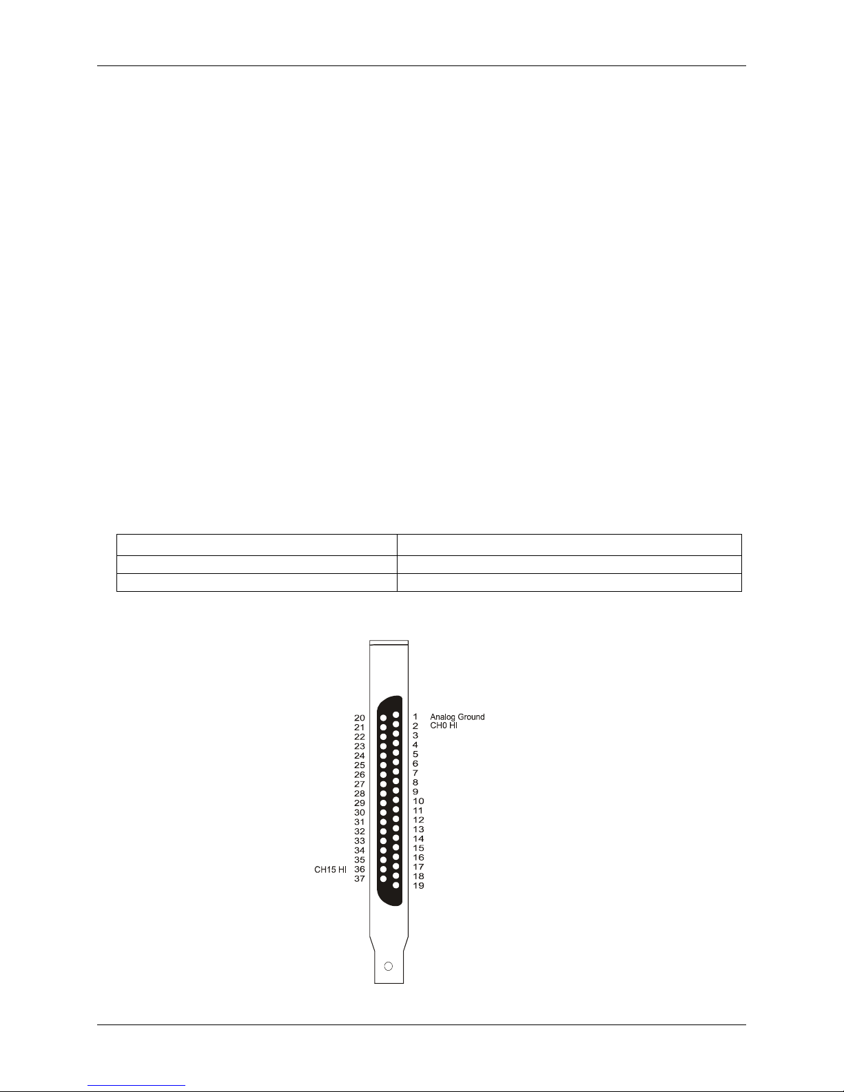
Pin out – main I/O connector
CJC INPUT
CH1 HI
CHh1 LO
CH3 HI
CH3 LO
CH5 HI
CH5 LO
CH7 HI
CH7 LO
CH9 HI
CH9 LO
CH11 HI
CH11 LO
CH13 HI
CH13 LO
CH14 HI
None
CH0 LO
CH2 HI
CH2 LO
CH4 HI
CH4 LO
CH6 HI
CH6 LO
CH8 HI
CH8 LO
CH10 HI
CH10 LO
CH12 HI
CH12 LO
Analog Ground
CH14 LO
CH15 LO
+15V Isolated Voltage Source
Figure 2-1. 37-pin board connector
2-3
Page 11

PCI-DAS-TC User's Guide Installing the PCI-DAS-TC
19
1
20
37
19
1
20
37
Figure 2-2. C37FFS-x cable
Field wiring, signal termination and conditioning
You can use the following screw terminal adapter board (with CJC sensor and isothermal block) to terminate
field signals and route them into the PCI-DAS-TC using the C37FFS-x cable.
! CIO-STA-TC – Isothermal block with CJC sensor. Details on this product are available on our web site at
www.mccdaq.com/cbicatalog/cbiproduct.asp?dept_id=116&pf_id=1209
.
2-4
Page 12

Chapter 3
Programming and Developing Applications
After following the installation instructions in Chapter 2, your board should now be installed and ready for use.
Although the board is part of the larger DAS family, in general there may be no correspondence among
registers for different boards. Software written at the register level for other DAS models will not function
correctly with your board.
Programming languages
Packaged applications programs
Many packaged application programs, such as SoftWIRE and HP-VEE™, now have drivers for your board. If
the package you own does not have drivers for your board, please fax or e-mail the package name and the
revision number from the install disks. We will research the package for you and advise how to obtain drivers.
or any other language, please refer to the Universal Library User's Guide (available on our web
).
Some application drivers are included with the Universal Library package, but not with the application package.
If you have purchased an application package directly from the software vendor, you may need to purchase our
Universal Library and drivers. Please contact us by phone, fax or e-mail:
! Phone: 508-946-5100 and follow the instructions for reaching Tech Support.
! Fax: 508-946-9500 to the attention of Tech Support
! Email: techsupport@mccdaq.com
Register-level programming
You should use the Universal Library or one of the packaged application programs mentioned above to control
your board. Only experienced programmers should try register-level programming.
If you need to program at the register level in your application, refer to the Register Map for the PCI-DAS-TC.
This document is available at www.mccdaq.com/registermaps/RegMapPCI-DAS-TC.pdf
.
3-1
Page 13
Functional Details
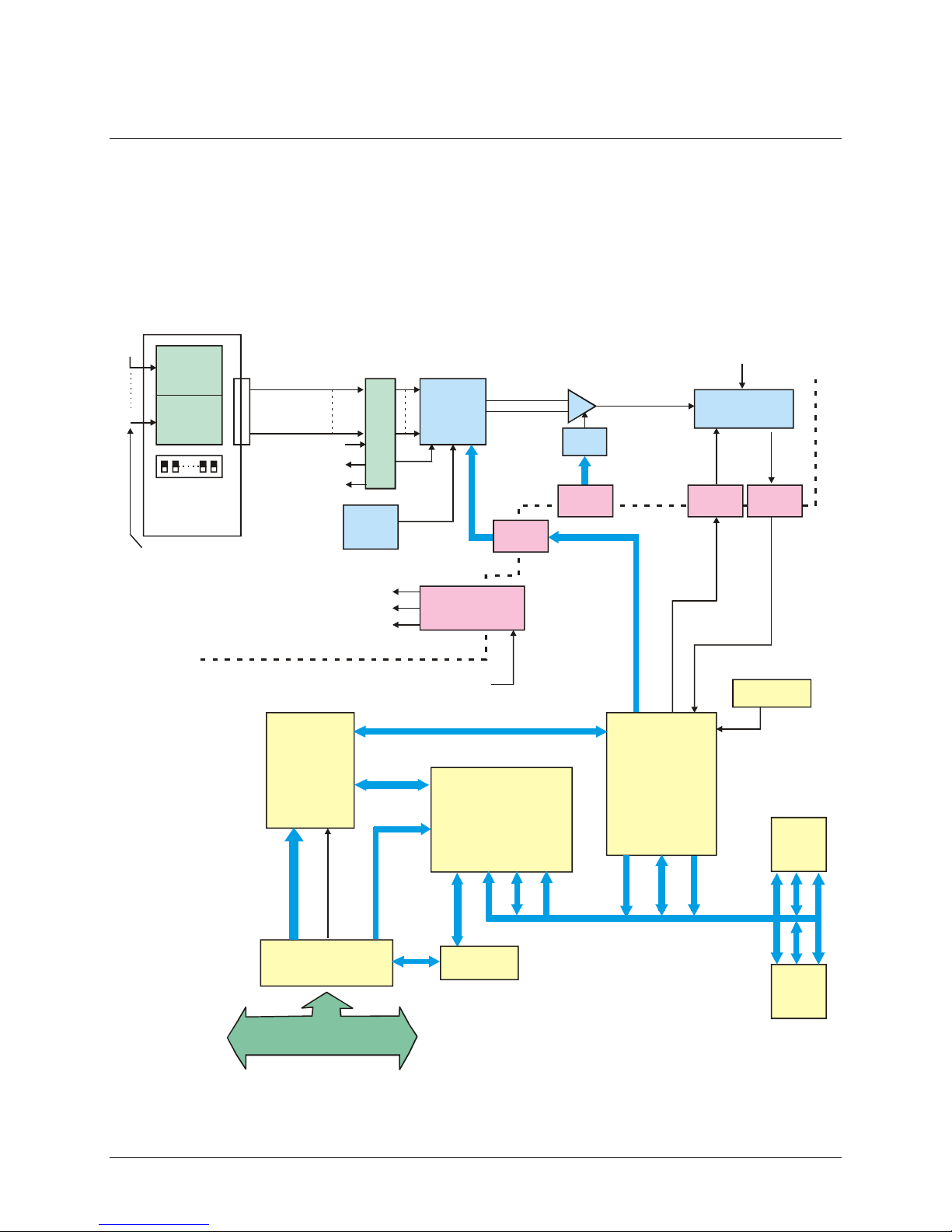
PCI-DAS-TC Block diagram
PCI-DAS-TC functions are illustrated in the block diagram shown here.
External
DAS-TC
Screw Terminal
0
Te rm i na l
15
Thermocouple
Detection
Switches
Thermocouple
Channels
Screw
CJC
Open
Input
TC Input
Channels
0 - 15
CJC
(For CJC) +15ISO
AGND
Input
Connector
37
Pin
+10V
Prec.
Ref
+5V ISO
+15V ISO
-15V ISO
Isolated Analog Input Section
20
Channel
Mux
+9.9V
Optical
Isolator
DC/DC
Converter
Input AMP
Gain
Mux
Optical
Isolator
SELECT:
CJC
Gain
Channel
Calibration
CLK
IN
Optical
Isolator
Chapter 4
+10V Ref
V/F
Converter
Fout
Optical
Isolator
Isolation
Barrier
Programmable
Logic
Control
Logic
Control
Registers
Control
Signals
PLX9050
PCI Interface
32-BIT, 33 MHz, 5V PCI BUS
System +5
Local
Control
Address
Board
Select
Data
D0:7
Dual Port
SRAM
Local BUS - Address, Data, Control
Data Bus
Transceiver
Processing and Control Section
Figure 4-1. PCI-DAS-TC functional block diagram
Oscillator
AM188
CPU
SRAM
Flash
EPROM
4-1
Page 14
PCI-DAS-TC User's Guide Functional Details
CIO-STA-TC screw terminal adapter board
The CIO-STA-TC is a specially configured screw terminal adapter board designed specifically for use with the
PCI-DAS-TC. The board has screw terminals for each thermocouple channel, a cold junction sensor integrated
into an isothermal bar, and the option of installing an "open thermocouple detection" circuit.
Each thermocouple input is made through two screw terminals — one positive (+) and one negative (-). Connect
the thermocouple wires to the appropriate terminals, connect the CIO-STA-TC to the PCI-DAS-TC, and your
board is ready for use.
Note the polarity when connecting the thermocouples
Be careful to observe correct polarity when connecting thermocouple wires or extension wires.
The CIO-STA-TC is available by itself (MCC part number CIO-STA-TC), or as part of a kit that includes the
PCI-DAS-TC board, five foot shielded cable, and DAS Wizard software (MCC part number PCI-DAS-TC.)
Open thermocouple detection
The only user configurable option in the CIO-STA-TC is the open thermocouple detection resistors. These are a
series of 20 MΩ resistors that can be connected between the + terminal of the thermocouple and a known
voltage that is larger than any allowable thermocouple output.
The 20 MΩ resistors are large enough so that they do not affect the readings from the thermocouples. If a
thermocouple junction should open, a 20 MΩ will drive the input voltage high enough so the software can
recognize that it is not a valid thermocouple reading.
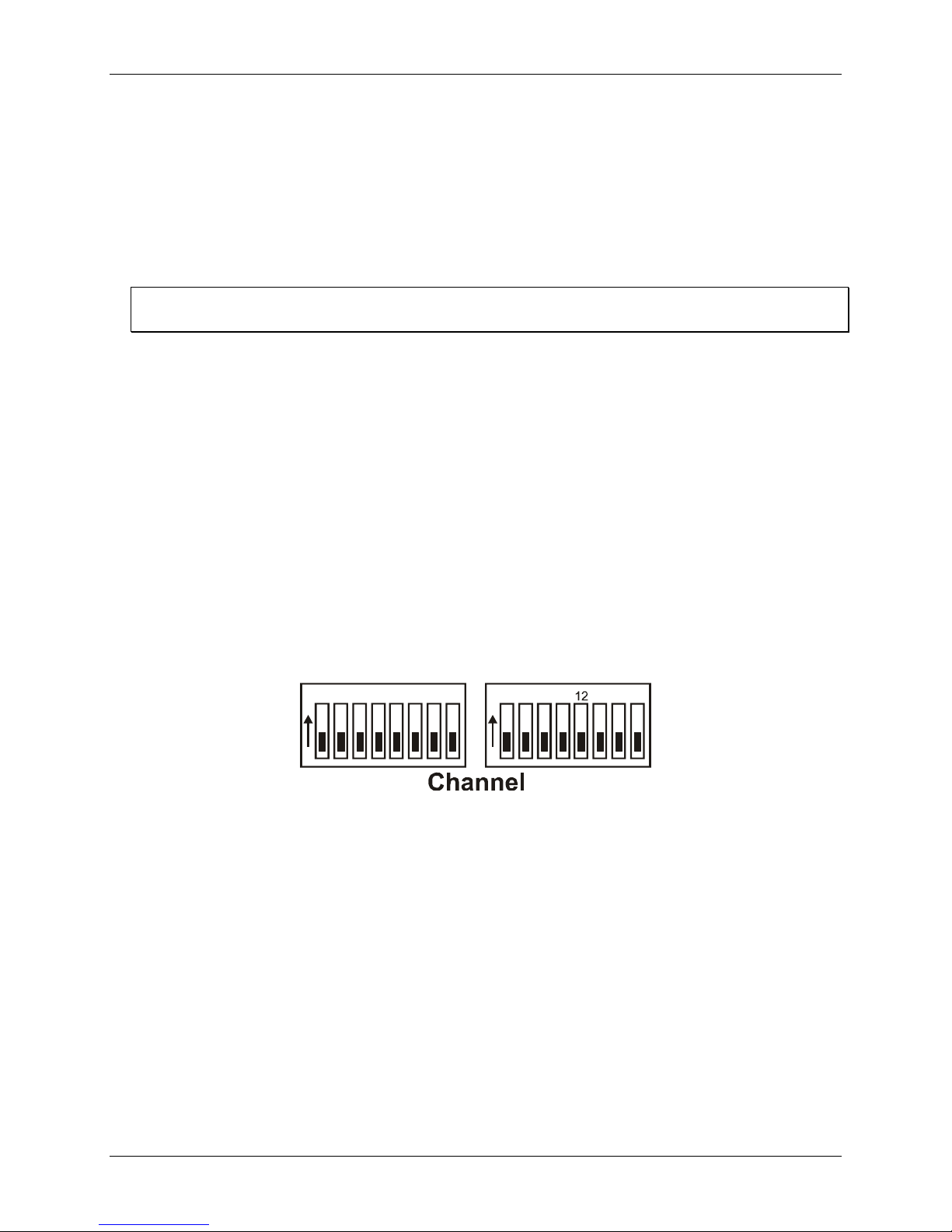
Open thermocouple detection circuitry is set via dip switches on the CIO-STA-TC. DIP switches are labeled,
and each channel has a switch. To enable open thermocouple detection for a channel, set the switch to ON (up,
towards the isothermal block). To disable the function, set the switch to OFF (down, towards the outside of the
board).
O
0123
N
Figure 4-2. PCI-DAS-TC functional block diagram
4567
O
891011
N
13 14 15
The PCI-DAS-TC is shipped with open thermocouple detection disabled.
Theory of operation
Isolated analog inputs
The analog input section of the PCI-DAS-TC consists of the following components:
! CJC (Cold Junction Compensation) sensor input
! 20 (differential) channel multiplexer
! Precision 9.90 V source
! Analog ground source
! Programmable gain amplifier suitable for scaling the seven thermocouple types
! High frequency, synchronous V-F A/D converter.
4-2
Page 15

PCI-DAS-TC User's Guide Functional Details
During normal operation, the V-F converts the CJC input, calibrates the gain at a Gain = 1 using the 9.9 V
input, offset using the ground input, and measures the thermocouple or voltage depending on the input type. The
CJC and the gain/offset values are stored in an onboard RAM for cold junction scaling and calibration. These
parameters are sampled continuously. Refer to the block diagram shown in Figure 4-1.
The V-F converter is an Analog Devices AD652 SVFC (Synchronous V-F Converter) which offers full scale
frequency up to 2 MHz and extremely low linearity error. The 4 MHz clock for the V/F converter is supplied by
TIMER1 and passes through opto-isolation. The output of the V/F converter, passing back through optoisolation, is supplied to TIMER0. TIMER0 is gated on by TIMER2 for a period dependent upon the specified
conversion frequency of 50Hz, 60Hz or 400Hz. At the end of the sampling period, the count in TIMER0
represents the voltage input. In general, the longer the count time, the higher the resolution and better the noise
reduction, unless in the case of periodic noise where the periodic frequency (for example, 50, 60, and 400 Hz) is
more effective in reducing the noise.
Processing and control
This section consists of control and decode logic, a microcontroller and local memory to perform channel
scanning, CJC measurements, calibration, linearization, averaging, and voltage/temperature translation. The
above parameters are set up from a configuration file which is downloaded by the PC to the microcontroller’s
local memory through the Dual Port RAM. After the microcontroller is given the command to start conversions,
these parameters are set on a channel-by-channel basis with data reported to the PC in the format specified by
the configuration file. For thermocouple inputs, the microcontroller reads the counter, adjusts the data based on
the CJC value and gain/offset calibration, then linearizes and converts the reading to the appropriate
temperature units.
To perform linearization, the microcontroller gets the raw frequency count from TIMER0, translates that into
bits, factors in the CJC correction and gain/offset calibration, then refers to a previously stored lookup table
stored in ROM. There is a separate table for each thermocouple. The lookup tables are a method to optimize the
linearization by using more reference points along areas of greatest temperature/voltage change instead of using
mathematical translation, which requires lengthy polynomial manipulation. Using lookup tables requires finding
two consecutive points, one greater and one less than the measured value, then interpolating the measured
temperature value.
Process flow
The PC itself performs very few functions for the PCI-DAS-TC. The DAS Wizard driver software (included
with the PCI-DAS-TC kit) will set up individual channels, including the thermocouple type, CJC on/off, voltage
or thermocouple gain, channel, and temperature units. The sample rate and sample averaging configuration are
also set by the driver for all channels. Both during initialization and when the configuration changes, this
information is passed to the CPU through the Dual Port RAM and stored for the specified channel. The PC then
notifies the CPU to start taking measurements. When the CPU completes a conversion, an interrupt is generated
so that the PC reads the data from the Dual Port RAM which the CPU had written to. The 32-bit floating point
data is stored in four consecutive locations in the Dual Port RAM. Refer to the "Dual Port RAM Memory Map"
section in the Register Map for the PCI-DAS-TC for more details on this process. This document is available on
our web site at www.mccdaq.com/registermaps/RegMapPCI-DAS-TC.pdf.
The on-board CPU has a much more complicated task. The CPU must set all the parameters for conversion of
the selected channel. After conversion, it must get the data, adjust it based on the stored CJC measurement,
calibrate against gain/offset error, linearize it based on lookup tables for each associated thermocouple type, and
report the data to the PC through the Dual Port RAM. During this process, the CPU goes to the next channel
and sets up the parameters for that channel to allow sufficient settling time before the next conversion begins.
4-3
Page 16

Chapter 5
Specifications
Typical for 25 °C unless otherwise specified.
Specifications in italic text are guaranteed by design.
Analog input
Table 1. Analog input specifications
A/D converter type AD652 V/F converter
Number of channels 16 differential thermocouple inputs, 1 CJC input
Programmable ranges
Voltage gains 1, 125, 166.7, 400
Thermocouple types J, K, E, T, R, S, B
A/D pacing Continuous conversions. Software-programmable for 50 Hz, 60 Hz, or 400 Hz
A/D trigger sources Software-triggered
Data transfer Single I/O register transfer through dual port RAM
Conversion rates (integrating time) 50 Hz, 60 Hz, 400 Hz
*Conversion rates (per channel)
Linearity error (A/D specs) ±0.05% @ 4 MHz clock
Gain drift (A/D specs) ±75 ppm/°C max
Zero drift (A/D specs) ±50 uV/°C max
Power supply rejection ratio 0.01 %/V
Overvoltage protection
CMRR @ 60 Hz 80 dB minimum
Input leakage current ±80 nA maximum
Input impedance 100 MegOhm minimum
Absolute maximum input voltage
Isolation to PC 500 V min through DC/DC converter and opto-isolators
−2.5 V to +10 V, −20 mV to +80 mV, −15 mV to +60 mV, −6.25 mV to 25 mV
Software programmable
25.0 msec @ 50 Hz typical, 25.5 msec maximum
21.6 msec @ 60 Hz typical, 22.1 msec maximum
7.4 msec @ 400 Hz typical, 7.9 msec maximum
*This is the total time to convert the channel, process the data, and provide a
delay to switch the gain and channel.
−40 V to +55 V
−40 V to +55 V
Accuracy and resolution
Gain Range Accuracy (Worst Case)
1
125
166.7
400
−2.5 to 10 V
−20 to 80 mV
−15 to 60 mV
−6.25 to 25 mV
Table 2. Voltage measurements
Resolution
@ 50 Hz @ 60 Hz @ 400 Hz
±0.01% of reading ±2.5 mV 312.5 µV 375 µV 2.5 mV
±0.01% of reading ±20 µV 2.5 µV 3.0 µV 20.0 µV
±0.01% of reading ±15 µV 1.88 µV 2.25 µV 15.0 µV
±0.02% of reading ±6.25 µV 0.781 µV 0.938 µV 6.25 µV
5-1
Page 17

PCI-DAS-TC User's Guide Specifications
Table 3. Thermocouple measurements (not including CJC errors)
TC
Type
J 0 to 750 °C ±0.5 °C 0.05 °C 0.05 °C 0.40 °C
K
E
T
R 0 to 1450 °C ±2.3 °C 0.06 °C 0.07 °C 0.44 °C
S 0 to 1450 °C ±2.3 °C 0.06 °C 0.08 °C 0.52 °C
B 0 to 1700 °C ±3.0 °C 0.07 °C 0.08 °C 0.54 °C
Range Accuracy (Worst Case)
−200 to 1250 °C
−200 to 900 °C
−200 to 350 °C
±1.4 °C 0.04 °C 0.05 °C 0.40°C
±1.1 °C 0.03 °C 0.04 °C 0.25 °C
±0.9 °C 0.03 °C 0.04 °C 0.25 °C
@ 50 Hz @ 60 Hz @ 400 Hz
Resolution
Miscellaneous
Table 4. Miscellaneous specifications
Averaging Moving average, 1 to 16 samples, software-selectable
Calibration
Processor reset
Watchdog timer 1.6 seconds nominal. Processor generates watchdog disable signal after boot-up.
Temperature units
Interrupts INTA# mapped to IRQn by PCIBIOS at boot time
Interrupt enable Programmable
Interrupt sources Dual port RAM when the processor mailbox has data.
Calibration is performed with each channel scan to remove offset and gain error. CJC
channel is also measured with each calibration.
On power-up, watchdog timeout, or software command. Processor boots within one
second of reset. Active low.
Programmable for conversion to °C or °F
Crystal oscillator
Table 5. Crystal oscillator specifications
Frequency 32 MHz
Frequency accuracy 100 ppm
CIO-STA-TC adapter
Table 6. CIO-STA-TC adapter specifications
CJC type AD592CN
Configuration CJC centered in an isothermal block on which the screw terminals have been mounted.
Channels 16 (plus CJC output)
Calibration error
Table 7. Calibration error specifications
@ 25 °C 0.3 °C typical, 0.5 °C maximum
25 °C to +105 °C 0.5 °C typical, 1.0 °C maximum
5-2
Page 18

PCI-DAS-TC User's Guide Specifications
e
Linearity error
Table 8. Linearity error specifications
−25 °C to +105 °C
0.1 °C typical, 0.35 °C maximum
Temperature coefficient 1 µA/°C typical
Long term stability 0.1 °C / month
Open thermocouple detect On/off switch selectable for each channel, full scale reading
Power consumption
Table 9. Power consumption specifications
+5 V operating 887 mA typical, 1441 mA maximum
Environmental
Table 10. Environmental specifications
Operating temperature range 0 to 50 °C
Storage temperature range
−20 to 70 °C
Humidity 0 to 90% non-condensing
Main connector and pin-out
Table 11. Main connector specifications
Connector type 37-pin D-type
Compatible cable C37FFS-x
Compatible accessory product
(with C37FFS-x cable)
CIO-STA-TC screw terminal adapter board
CJC INPUT
CH1 HI
CHh1 LO
CH3 HI
CH3 LO
CH5 HI
CH5 LO
CH7 HI
CH7 LO
CH9 HI
CH9 LO
CH11 HI
CH11 LO
CH13 HI
CH13 LO
CH14 HI
None
CH0 LO
CH2 HI
CH2 LO
CH4 HI
CH4 LO
CH6 HI
CH6 LO
CH8 HI
CH8 LO
CH10 HI
CH10 LO
CH12 HI
CH12 LO
Analog Ground
CH14 LO
CH15 LO
+15V Isolated Voltage Sourc
5-3
Page 19

Declaration of Conformity
Manufacturer: Measurement Computing Corporation
Address: 10 Commerce Way
Suite 1008
Norton, MA 02766
USA
Category: Electrical equipment for measurement, control and laboratory use.
Measurement Computing Corporation declares under sole responsibility that the product
PCI-DAS-TC
to which this declaration relates is in conformity with the relevant provisions of the following standards or other
documents:
EU EMC Directive 89/336/EEC: Electromagnetic Compatibility, EN55022 (1995), EN55024 (1998)
Emissions: Group 1, Class B
! EN55022 (1995): Radiated and Conducted emissions.
Immunity: EN55024
! EN61000-4-2 (1995): Electrostatic Discharge immunity, Criteria A.
! EN61000-4-3 (1997): Radiated Electromagnetic Field immunity Criteria A.
! EN61000-4-4 (1995): Electric Fast Transient Burst immunity Criteria A.
! EN61000-4-5 (1995): Surge immunity Criteria A.
! EN61000-4-6 (1996): Radio Frequency Common Mode immunity Criteria A.
! EN61000-4-8 (1994): Power Frequency Magnetic Field immunity Criteria A.
! EN61000-4-11 (1994): Voltage Dip and Interrupt immunity Criteria A.
Declaration of Conformity based on tests conducted by Chomerics Test Services, Woburn, MA 01801, USA in
September, 2001. Test records are outlined in Chomerics Test Report #EMI3053.01.
We hereby declare that the equipment specified conforms to the above Directives and Standards.
Carl Haapaoja, Director of Quality Assurance
Page 20

HM PCI-DAS-TC.doc
Measurement Computing Corporation
10 Commerce Way
Suite 1008
Norton, Massachusetts 02766
(508) 946-5100
Fax: (508) 946-9500
E-mail: info@mccdaq.com
www.mccdaq.com
 Loading...