

Page 1
Page 2

PC-CARD-D24/CTR3
Digital I/O and Counter Board
User’s Guide
Document Revision 6, April, 2007
© Copyright 2007, Measurement Computing Corporation
Page 3
Your new Measurement Computing product comes with a fantastic extra —
Management committed to your satisfaction!
Thank you for choosing a Measurement Computing product—and congratulations! You own the finest, and you can now enjoy
the protection of the most comprehensive warranties and unmatched phone tech support. It’s the embodiment of our mission:
To provide data acquisition hardware and software that will save time and save money.
Simple installations minimize the time between setting up your system and actually making measurements. We offer quick and
simple access to outstanding live FREE technical support to help integrate MCC products into a DAQ system.
Limited Lifetime Warranty: Most MCC products are covered by a limited lifetime warranty against defects in materials or
workmanship for the life of the product, to the original purchaser, unless otherwise noted. Any products found to be defective in
material or workmanship will be repaired, replaced with same or similar device, or refunded at MCC’s discretion. For specific
information, please refer to the terms and conditions of sale.
Harsh Environment Program: Any Measurement Computing product that is damaged due to misuse, or any reason, may be
eligible for replacement with the same or similar device for 50% of the current list price. I/O boards face some harsh
environments, some harsher than the boards are designed to withstand. Contact MCC to determine your product’s eligibility for
this program.
30 Day Money-Back Guarantee: Any Measurement Computing Corporation product may be returned within 30 days of
purchase for a full refund of the price paid for the product being returned. If you are not satisfied, or chose the wrong product by
mistake, you do not have to keep it.
These warranties are in lieu of all other warranties, expressed or implied, including any implied warranty of merchantability or
fitness for a particular application. The remedies provided herein are the buyer’s sole and exclusive remedies. Neither
Measurement Computing Corporation, nor its employees shall be liable for any direct or indirect, special, incidental or
consequential damage arising from the use of its products, even if Measurement Computing Corporation has been notified in
advance of the possibility of such damages.
Trademark and Copyright Information
Measurement Computing Corporation, InstaCal, Universal Library, and the Measurement Computing logo are either trademarks
or registered trademarks of Measurement Computing Corporation. Refer to the Copyrights & Trademarks section on
mccdaq.com/legal for more information about Measurement Computing trademarks. Other product and company names
mentioned herein are trademarks or trade names of their respective companies.
© 2007 Measurement Computing Corporation. All rights reserved. No part of this publication may be reproduced, stored in a
retrieval system, or transmitted, in any form by any means, electronic, mechanical, by photocopying, recording, or otherwise
without the prior written permission of Measurement Computing Corporation.
Notice
Measurement Computing Corporation does not authorize any Measurement Computing Corporation product for use
in life support systems and/or devices without prior written consent from Measurement Computing Corporation.
Life support devices/systems are devices or systems that, a) are intended for surgical implantation into the body, or
b) support or sustain life and whose failure to perform can be reasonably expected to result in injury. Measurement
Computing Corporation products are not designed with the components required, and are not subject to the testing
required to ensure a level of reliability suitable for the treatment and diagnosis of people.
HM PC-CARD-D24_CTR3.doc
3
Page 4

4
Page 5

Table of Contents
Preface
About this User's Guide .......................................................................................................................6
What you will learn from this user's guide.........................................................................................................6
Conventions in this user's guide.........................................................................................................................6
Where to find more information.........................................................................................................................6
Chapter 1
Introducing the PC-CARD-D24/CTR3..................................................................................................7
Overview: PC-CARD-D24/CTR3 features ........................................................................................................7
PC-CARD-D24/CTR3 block diagram .............................................................................................................................. 7
Software features................................................................................................................................................7
Chapter 2
Installing the PC-CARD-D24/CTR3......................................................................................................8
What comes with your PC-CARD-D24/CTR3 shipment?.................................................................................8
Hardware .......................................................................................................................................................................... 8
Additional documentation
Optional com
ponents........................................................................................................................................................ 8
Unpacking the PC-CARD-D24/CTR3 ...............................................................................................................9
Installing the software ........................................................................................................................................9
Installing the PC-CARD-D24/CTR3 ..................................................................................................................9
If your PCMCIA card is not detected ............................................................................................................................... 9
Connecting the board for I/O operations..........................................................................................................10
Connectors, cables – main I/O connector ........................................................................................................................10
Pin out – main I/O
Field wiring and signal term
Calibrating the PC-CARD-D24/CTR3.............................................................................................................14
Chapter 3
Programming and Developing Applications....................................................................................15
Programming languages...................................................................................................................................15
Packaged applications programs ......................................................................................................................15
Counter operational modes...............................................................................................................................15
Register-level programming.............................................................................................................................15
Chapter 4
Specifications......................................................................................................................................16
Digital input/output ..........................................................................................................................................16
Counter.............................................................................................................................................................16
Power consumption..........................................................................................................................................17
Miscellaneous...................................................................................................................................................17
Environmental ..................................................................................................................................................17
Connector and pin out ......................................................................................................................................17
................................................................................................................................................. 8
connector...........................................................................................................................................10
ination.................................................................................................................................14
5
Page 6
About this User’s Guide
What you will learn from this user's guide
This user's guide describes the Measurement Computing PC-CARD-D24/CTR3 data acquisition
board and lists hardware specifications.
Conventions in this user's guide
For more information
Text presented in a box signifies additional information related to the subject matter.
Caution! Shaded caution statements present information to help you avoid injuring yourself and others,
damaging your hardware, or losing your data.
bold text Bold text is used for the names of objects on a screen, such as buttons, text boxes, and check boxes.
italic text Italic text is used for the names of manuals an d help topic titles, and to emphasize a word or phrase.
Where to find more informati on
Additional information about PC-CARD-D24/CTR3 hardware is available on our website at
www.mccdaq.com. You can also contact Measurement Computing Corporation with specific questions.
Preface
Knowledgebase: kb.mccdaq.com
Tech support form: www.mccdaq.com/support/support_form.aspx
Email: techsupport@mccdaq.com
Phone: 508-946-5100 and follow the instructions for reaching Tech Support
For international customers, co ntac t your local distributor. Refer to the I nter national Distributors section on our
website at www.mccdaq.com/International
.
6
Page 7
Chapter 1
Introducing the PC-CARD-D24/CTR3
Overview: PC-CARD-D24/CTR3 features
The PC-CARD-D24/CTR3 is a data acquisition and control board for IBM PC compatible computers with
PCMCIA/PC-CARD type slots. The primary functional elements consist of the following:
An 82C55 chip using TTL logic for 24 bi-directional digital I/O channels.
An 82C54 counter/timer chip that has three, 16-bit down-counters.
Under software control, the counters can be clocked internally from a 10 or 1 MHz crystal oscillator,
clocked externally, or chained to yield a 32- or 48-bit counter. Each counter can be gated (disabled) with
an external gate signal
The 24 digital I/O channels are divided into three ports — A, B, and C. Each port has eight I/O channels. At
power-on or reset, the digital lines are set as inputs. The board provides three independently programmable and
functioning 16-bit down-counters. You can access the clock input, gate, and output for each counter.
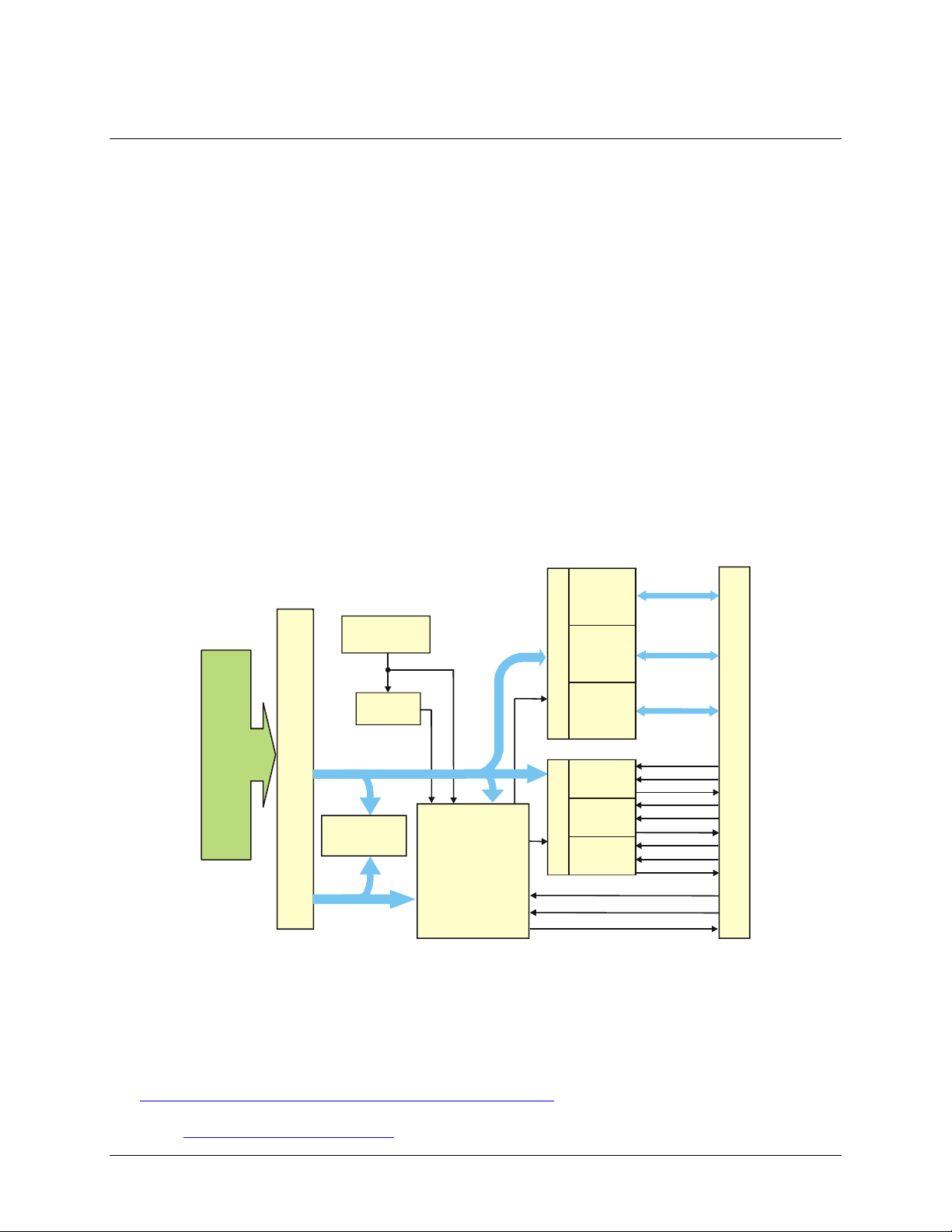
PC-CARD-D24/CTR3 block diagram
PC-CARD-D24/CTR3 functions are illustrated in the block diagram shown here.
Host Bus Adapter
Software features
Digital I/O
Digital I/O
Port
Port
8-bits
8-bits
Data Bus
Attribute
Memory
PCMCIA Bus Connector P1 (68-pin)
Address Bus
10 MHz
Oscillator
10 MHz
Divide
by 10
1 MHz
Controller
FPGA
Digital I/O
Digital I/O
Port
Port
8-bits
8-bits
Control
Control
Digital I/O
Digital I/O
Port
Port
8-bits
8-bits
Digital I/O
Counter
Port
8-bits
Counter
Digital I/O
Control
Port
Counter
8-bits
Control
1
2
3
Figure 1. PC-CARD-D24/CTR3 functional block diagram
A0 (7:0)
B0 (7:0)
C0 (7:0)
CTR1 CLK
CTR1 GATE
CTR1 OUT
CTR2 CLK
CTR2 GATE
CTR2 OUT
CTR3 CLK
CTR3 GATE
CTR3 OUT
INT ENABLE
EXT INT
1 MHz OUT
P2 Connector (50-pin)
For information on the features of InstaCal and the other software included with your PC-CARD-D24/CTR3,
refer to the Quick Start Guide th
at shipped with your device. The Quick Start Guide is also available in PDF at
www.mccdaq.com/PDFs/manuals/DAQ-Software-Quick-Start.pdf.
Check
www.mccdaq.com/download.htm
for the latest software version.
7
Page 8

Installing the PC-CARD-D24/CTR3
What comes with your PC-CARD-D24/CTR3 shipment?
The following items are shipped with the PC-CARD-D24/CTR3.
Hardware
PC-CARD-D24/CTR3
Chapter 2
Additional documentation
In addition to this hardware user's guide, you should also receive the Quick Start Guide (available in PDF at
www.mccdaq.com/PDFs/manuals/DAQ-Software-Quick-Start.pdf). This booklet supplies a brief description
of the software you received with your PC-CARD-D24/CTR3 and information regarding installation of that
software. Please read this booklet completely before installing any software or hardware.
Optional components
Cables
CPCC-50F-39 CPCC-50M-4 C50FF-x
Signal termination and conditioning accessories
M
CC provides signal conditioning and termination products for use with the PC-CARD-D24/CTR3. Re
to Field wiring and signal termination
on page 11 for a complete list of compatible accessory products.
fer
8
Page 9

PC-CARD-D24/CTR3 User's Guide Installing the PC-CARD-D24/CTR3
Unpacking the PC-CARD-D24/CTR3
As with any electronic device, you should take care while handling to avoid damage from static
electricity. Before removing the PC-CARD-D24/CTR3 from its packaging, ground yourself using a wrist strap
or by simply touching the computer chassis or other grounded object to eliminate any stored static charge.
If any components are missing or damaged, notify Measurement Computing Corporation immediately by
phone, fax, or e-mail:
Phone: 508-946-5100 and follow the instructions for reaching Tech Support.
Fax:
Email: techsupport@mccdaq.com
508-946-9500 to the attention of Tech Support
Installing the software
Refer to the Quick Start Guide for instructions on installing the software on the Measurement Computing Data
Acquisition Software CD. This booklet is available in PDF at www.mccdaq.com/PDFs/manuals/DAQ-
Software-Quick-Start.pdf.
Installing the PC-CARD-D24/CTR3
The PC-CARD-D24/CTR3 board is completely plug-and-play. There are no switches or jumpers to set. To
install your board, follow the steps below.
Install the MCC DAQ software before you install your board
The driver needed to run your board is installed with the MCC DAQ software. Therefore, you need to install
the MCC DAQ software before you install your board. Refer to the Quick Start Guide for instructions on
installing the software.
To install your PC-Card, do the following:
Insert the card into a free PC Card/PCMCIA type II or III slot. The key
inserted in the correct orientation.
You do not
hear an insertion beep when you insert the card.
Windows automatically detects, recognizes, and configures the PC-CARD. You should hear an insertion beep
when you insert the card into the slot. To verify that the card is recognized, go to Control Panel\System\Device
Manager and the card should now appear under "DAS Component."
have to turn the computer off. The system is designed for power-on installation. You shoul
F
igure 2. End view of the 50-pin PC-CARD connector showing proper orientation
helps to insure that the cable is
d
If your PCMCIA card is not detected
If the card is not detected by Windows, and you are not prompted for a driver after inserting the card, check
that your computer's 32-bit PCMCIA drivers are installed and enabled. Do the following:
1.
From your desktop, right-click on My Computer and select
opens.
2.
Select the
Hardware tab and click on the Device Manager button.
9
Properties. The System Properties dialog
Page 10

PC-CARD-D24/CTR3 User's Guide Installing the PC-CARD-D24/CTR3
p
3.
Verify that "PCMCIA adapters" is listed in the Device Manager. If you don’t find this entry, or if the
properties for the adapter indicate "this device is not working," you need to install or update your PCMCIA
adapter drivers.
o
If the PCMCIA adapter is not listed, use the
If the PCMCIA adapter is listed but not working, use the
o
Add New Hardware Wizard to install PCMCIA support.
Update Driver option to install the
appropriate drivers.
After performing the update procedure, reboot your PC and insert your card again.
Connecting the board for I/O operations
Connectors, cables – main I/O connector
The table below lists the board connector, applicable cables, and compatible accessory products.
Board connector, cables, and accessory equipment
Connector type 50-pin connector
Compatible cables
Compatible accessory
products
CPCC-50F-39: 50-pin Micro connector to 50-pin female IDC, one-meter cable (39 inches).
CPCC-50M-4: 50-pin Micro connector to 50-pin male IDC, 4 inch adapter cable.
and
C50FF-x: 50-
CIO-MINI50
CIO-SPADE50
CIO-TERM100
SCB-50
SSR-RACK24
CIO-ERB24
CIO-SERB24
in IDC female to female cable. x = length in feet.
Pin out – main I/O connector
Figure 3
mechanically keyed to insure that the cable is inserted correctly.
shows a PC-CARD-D24/CTR3 case looking into the male mini-connector. The connector is
Figure 3. 50-pin I/O mini-connector
10
Page 11

PC-CARD-D24/CTR3 User's Guide Installing the PC-CARD-D24/CTR3
Cabling
Measurement Computing offers two cables for connecting the PC-CARD-D24/CTR3 to a screw-type terminal
board or other signal conditioning interface board:
The CPCC-50F-39 cable: 39 inches (990 mm) long; and compatible with standard 50-pin screw terminal
products.
The CPCC-50M-4 cable: four-inch long adapter cable; required when using a C50FF-x series cable.
2GND
4GND
6GND
8GND
10 GND
12 GND
14 GND
16 GND
18 GND
20 GND
22 GND
24 GND
26 A6
28 A4
30 A2
32 A0
34 B6
36 B4
38 B2
40 B0
42 C6
44 C4
46 C2
48 C0
50 GND
1
50
PC-CARD end
Ext Int 1
Int Enable 3
CTR1 CLK 5
CTR1 Gate 7
CTR1 Out 9
CTR2 CLK 11
CTR2 Gate 13
CTR2 Out 15
CTR3 CLK 17
CTR3 Gate 19
CTR3 Out 21
1 MHz Out 23
A7 25
A5 27
A3 29
A1 31
B7 33
B5 35
B3 37
B1 39
C7 41
C5 43
C3 45
C1 47
+5V 49
CPCC-50M-4 cable end
(connect to C50FF-x)
Figure 4. Cable map — PC-CARD to CPCC-50M-4
1Ext Int
3Int Enable
5CTR1 Clk
7CTR1 Gate
9CTR1 Out
11 CTR2 Clk
13 CTR2 Gate
15 CTR2 Out
17 CTR3 Clk
19 CTR3 Gate
21 CTR3 Out
23 1 MHz Out
25 A7
27 A5
29 A3
31 A1
33 B7
35 B5
37 B3
39 B1
41 C7
43 C5
45 C3
47 C1
49 +5V
1
50
PC-CARD end
GND 2
GND 4
GND 6
GND 8
GND 10
GND 12
GND 14
GND 16
GND 18
GND 20
GND 22
GND 24
A6 26
A4 28
A2 30
A0 32
B6 34
B4 36
B2 38
B0 40
C6 42
C4 44
C2 46
C0 48
GND 50
(connect to screw terminal or relay boards)
CPCC-50F-39 cable end
Figure 5. Cable map — PC-CARD to CPCC-50F-39
11
Page 12

PC-CARD-D24/CTR3 User's Guide Installing the PC-CARD-D24/CTR3
Figure 6
shows a map of the two methods of cabling the PC-CARD-D24/CTR3 to various screw terminal or
signal conditioning boards.
PC-CARD-D24/CTR3
PC-CARD-D24/CTR3
CPCC-50F-39
49
Key
50
RELAYS
SSR-RACK24
CIO-ERB24
CIO-SERB24
CPCC-50M-4
C50FF-#
TERMINALS
CIO-MINI50
CIO-SPADE 50
CIO-TERM100
SCB-50
OR
TERMINALS
CIO-MINI50
CIO-SPADE 50
CIO-TERM100
CPCC-50F-39
SCB-50
Figure 6. Connecting to screw terminal or relay boards
RELAYS
SSR-RACK24
CIO-ERB24
CIO-SERB24
50
1
2
50-pin female IDC connector.
Connect to the I/O connector
Figure 7. CPCC-50F-39 cable connections
Details on the CPCC-50F-39 cable are available on our web site at
www.mccdaq.com/cbicatalog/cbiproduct.asp?dept_id=105&pf_id=1379
1
Dot
50-pin micro connector.
on the PC-CARD
with the dot facing UP.
.
12
Page 13

PC-CARD-D24/CTR3 User's Guide Installing the PC-CARD-D24/CTR3
CPCC-50M-4
If your application requires a cable that is longer than one meter in length, use the CPCC-50M-4 four-inch
cable, and connect to a C50FF-x cable.
50
2
49
1
50-pin micro connector.
Connect to the I/O connector
50-pin male IDC connector.
Connect to a C50FF-x cable.
on the PC-CARD
with the dot facing UP.
Figure 8. CPCC-50M-4 cable connections
Details on the CPCC-50M-4 cable are available on our web site at
www.mccdaq.com/cbicatalog/cbiproduct.asp?dept_id=96&pf_id=1380
C50FF-x
2
1
The red stripe
identifies pin # 1
50
1
Dot
.
2
1
50
50-pin female
IDC connector
49
Figure 9. C50FF-x cable
Details on the C50FF-x cable are available on our web site at
www.mccdaq.com/cbicatalog/cbiproduct.asp?dept_id=104&pf_id=136
13
.
50
50-pin female
IDC connector
49
Page 14
PC-CARD-D24/CTR3 User's Guide Installing the PC-CARD-D24/CTR3
Field wiring and signal termination
You can use the following cabling, screw termination, and signal conditioning products with the CPCC-50F-39
cable, or with the CPCC-50M-4 and C50FF-x cables:
CIO-MINI50 – 50-pin screw terminal board. Details on this product are available on our web site at
www.mccdaq.com/cbicatalog/cbiproduct.asp?dept_id=102&pf_id=258
IO-TERM100 – 100-pin screw terminal board (Two 50-pin IDC connectors). Details on this product
C
avai
lable on our web site at www.mccdaq.com/cbicatalog/cbiproduct.asp?dept_id=102&pf_id=281
IO-SPADE50 — 16" X 4" termination panel which mates with both 37-pin and 50-pin connect
C
Details on this product
SC
SSR
CIO-ERB24 – 24 Form
CIO-SERB24 – 24 Form
B-50 – 50 conductor, shielded signal connection/screw terminal box provides two independent 50-pi
connect
www.mccdaq.com/cbicatalog/cbiproduct.asp?dept_id=196&pf_id=1168
product are available on our web site at
www.mccdaq.com/cbicatalog/cbiproduct.asp?dept_id=122&pf_id=1193
t
www.mccdaq.com/cbicatalog/cbiproduct.asp?dept_id=123&pf_id=241
replaceable relays. Details on this produc
www.m
ions. Details on this product are available on our web site at
-RACK24 – 24-channel, solid-state relay mounting rack for digital signal conditioning. Details on this
his product are available on our web site at
ccdaq.com/cbicatalog/cbiproduct.asp?dept_id=123&pf_id=678
are available on our web site at www.mccdaq.com/pdfs/specs/screw-spec.pdf.
C relays, 6 Amp relay accessory board for digital signa
C relays, 10 Amp, fault detecting relay accessory board with socketed and field-
t are available on our web site at
.
are
.
ors.
n
.
.
l conditioning. Details on
.
.
Information on signal connections
General information regarding signal connection and configuration is available in the Guide to
Signal Connections (available at www.mccdaq.com/pdfs/DAQ-Signal-Connections.pdf).
Calibrating the PC-CARD-D24/CTR3
No calibration is required. There are no socketed or user-serviceable parts in the PC-CARD-D24/CTR3. The
case cannot be opened. Opening the case will void your warranty. If your PC-CARD-D24/CTR3 requires
service, contact the factory for an RMA# and return it
14
Page 15

Chapter 3
Programming and Developing Applications
After following the installation instructions in Chapter 2, your board should now be installed and ready for use.
In general there may be no correspondence among registers for different boards. Software written at the
register-level for other models does not function correctly with your board.
Programming languages
Packaged applications programs
Many packaged application programs now have drivers for your board. If the package you own does not have
drivers for the board, please fax or e-mail the package name and the revision number from the install disks. We
will research the package for you and advise how to obtain drivers.
Some application drivers are included with the Universal Library package, but not with the application package.
If you have purchased an application package directly from the software vendor, you may need to purchase our
Universal Library and drivers. Please contact us by phone, fax or e-mail:
or any other language, please refer to the Universal Library User's Guide (available on our web
).
Phone: 508-946-5100 and follow the instruc
Fax:
Email: techsupport@mccdaq.com
508-946-9500 to the attention of Tech Support
tions for reaching Tech Support.
Counter operational modes
The 82C54 counter can be programmed to operate in one of six modes as follows:
Mode 0: Interrupt on Terminal Count. Typically used for event counti
ode 1: Hardware Re-triggerable One-Shot
M
M
ode 2: Rate Generator (divide by N-counter used for real-time clock interrupt
Mode 3: Square-Wave mode. Typically used for baud rate generation.
ode 4: Software-triggered counting m
M
M
ode 5: Hardware-Triggered Strobe -
To program
.
ode.
Re-triggerable.
ng.
).
Register-level programming
You should use the Universal Library or one of the packaged application programs mentioned above to control
your board. Only experienced programmers should try register-level programming.
.
15
Page 16
b
Specifications
Typical for 25 °C unless otherwise specified.
Specifications in italic text are guaranteed by design.
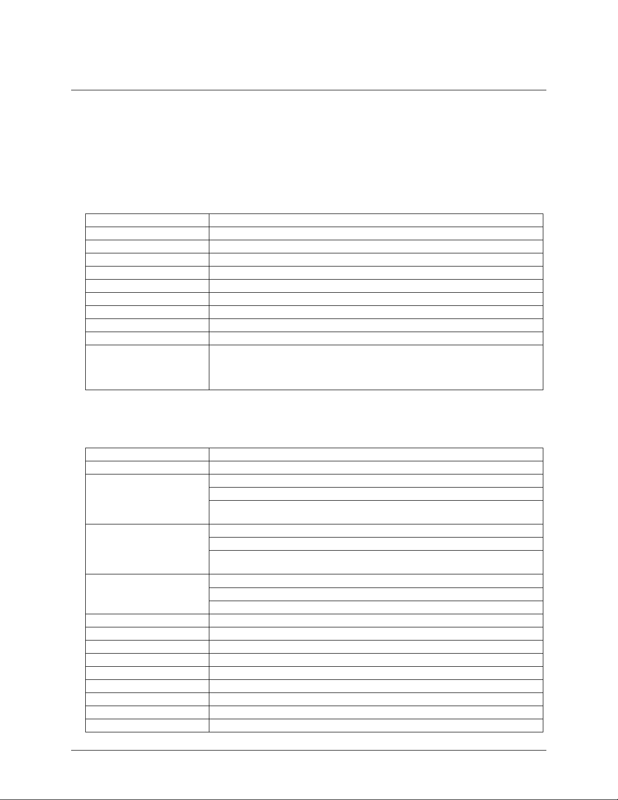
Digital input/output
Table 1. Digital I/O specifications
Digital type 82C55
Configuration 2 banks of 8, 2 banks of 4, programmable by bank as input or output
Number of channels 24 I/O
Output high 3.0 volts min @ -2.5 mA
Output low 0.4 volts max @ 2.5 mA
Input high 2.0 volts min, 5.5 volts absolute max
Input low 0.8 volts max, -0.5 volts absolute min
Power-up / reset state Input mode (high impedance)
Interrupts Programmable levels 2-15
Interrupt enable Programmable
Interrupt sources Programmable:
External (Ext Int)
Internal (counter 1 output, counter 2 output, counter 3 output, 82C55 port C bit C0 or
it C3)
Chapter 4
Counter
Table 2. Counter specifications
Counter type 82C54
Configuration 3 down counters per 82C54, 16 bits each
Counter 1 - Independent user
counter
Counter 2 - Independent user
counter
Counter 3 - Independent user
counter
Clock input frequency 10 MHz max
High pulse width (clock input) 30 ns min
Low pulse width (clock input) 50 ns min
Gate width high 50 ns min
Gate width low 50 ns min
Input low voltage 0.8 V max
Input high voltage 2.0 V min
Output low voltage 0.4 V max
Output high voltage 3.0 V min
Source: Programmable internal 10 MHz or external (CTR1 CLK)
Gate: External (CTR1 Gate), pulled high (enabled) by 10 k resistor
Output: Available at user connector (CTR1 Out), may also be programmed to
connect to counter 2 clock.
Source: Programmable internal 10 MHz , external (CTR2 CLK) or CTR1 Out
Gate: External (CTR2 Gate), pulled high (enabled) by 10 k resistor
Output: Available at user connector (CTR2 Out), may be programmed to
connect to counter 3 clock
Source: Programmable internal 1 MHz , external (CTR3 CLK) or CTR2 Out
Gate: External (CTR3 Gate), pulled high (enabled) by 10k resistor
Output: Available at user connector (CTR3 Out)
16
Page 17

PC-CARD-D24/CTR3 User's Guide Specifications
S
p
Crystal oscillator Frequency: 10 MHz
Frequency accuracy: 50 ppm
Miscellaneous: Available (divided by 10) at user connector (1 MHz Out)
Power consumption
Table 3. Power consumption specifications
+5V operating 45 mA typical, 65 mA max
Miscellaneous
Table 4. Miscellaneous specifications
+5 Volts DC
Available at I/O connector (+5V Power)
Protected by resettable fuse:
Hold current: 350 mA
Trip current: 700 mA
Trip and recovery time: 100 m
Environmental
Table 5. Environmental specifications
Operating temperature range 0 to 70 °C
Storage temperature range -40 to 100 °C
Humidity 0 to 95% non-condensing
Connector and pin out
Table 6. Connector specifications
Connector type 50-pin connector
Compatible cables
Compatible accessory products CIO-MINI50
CPCC-50F-39: 50-pin Micro connector to 50-pin female IDC, one-meter cable
(39 inches).
CPCC-50M-4: 50-pin Micro connector to 50-pin male IDC, 4 inch adapter cable.
and
C50FF-x: 50-
CI-SPADE50
CIO-TERM100
SCB-50
SSR-RACK24
CIO-ERB24
CIO-SERB24
in IDC female to female cable. x = length in feet.
17
Page 18
PC-CARD-D24/CTR3 User's Guide Specifications
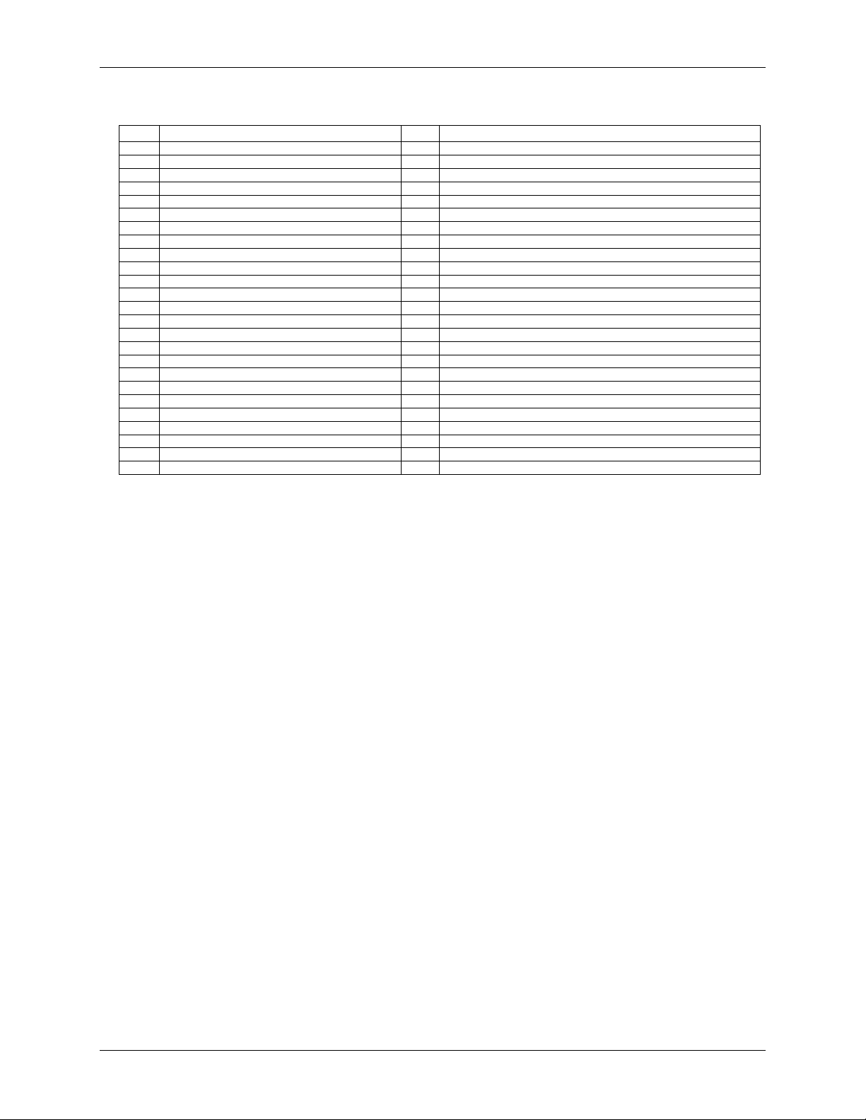
Table 7. Connector pin out
Pin Signal Name Pin Signal Name
1 Ext Int 26 A6
2 GND 27 A5
3 Int Enable 28 A4
4 GND 29 A3
5 CTR1 CLK 30 A2
6 GND 31 A1
7 CTR1 Gate 32 A0
8 GND 33 B7
9 CTR1 Out 34 B6
10 GND 35 B5
11 CTR2 CLK 36 B4
12 GND 37 B3
13 CTR2 Gate 38 B2
14 GND 39 B1
15 CTR2 Out 40 B0
16 GND 41 C7
17 CTR3 CLK 42 C6
18 GND 43 C5
19 CTR3 Gate 44 C4
20 GND 45 C3
21 CTR3 Out 46 C2
22 GND 47 C1
23 1 MHz Out 48 C0
24 GND 49 +5V
25 A7 50 GND
18
Page 19

Declaration of Conformity
Manufacturer: Measurement Computing Corporation
Address: 10 Commerce Way
Suite 1008
Norton, MA 02766
USA
Category: Electrical equipment for measurement, control and laboratory use.
Measurement Computing Corporation declares under sole responsibility that the product
PC-CARD-D24/CTR3
to which this declaration relates is in conformity with the relevant prov isions of the following standards or
other documents:
EU EMC Directive 89/336/EEC: Electromagnetic Compatibility, EN 61326 (1997) Amendment 1 (1998)
Emissions: Group 1, Class A
EN 55011 (1990)/CISPR 11: Radiated and Conducted emissions.
Immunity: EN61326, Annex A
IEC 1000-4-2 (1995): Electrostatic Discharge immunity, Criteria C.
IEC 1000-4-3 (1995): Radiated Electromagnetic Field immunity Criteria C.
IEC 1000-4-4 (1995): Electric Fast Transient Burst immunity Criteria C.
IEC 1000-4-5 (1995): Surge immunity Criteria A.
IEC 1000-4-6 (1996): Radio Frequency Common Mode immunity Criteria C.
IEC 1000-4-11 (1994): Voltage Dip and Interrupt immunity Criteria A.
Tests to IEC 1000-4-8 were not required. The PC cards do not contain components that would be susceptible
to magnetic fields.
Declaration of Conformity based on tests conducted by Chomerics Test Services, Woburn, MA 01801, USA in
July, 2004. Test records are outlined in Chomerics Test Report #EMI3930.04.
We hereby declare that the equipment specified conforms to the above Directives and Standards.
Carl Haapaoja, Director of Quality Assurance
Page 20

Measurement Computing Corporation
10 Commerce Way
Suite 1008
Norton, Massachusetts 02766
(508) 946-5100
Fax: (508) 946-9500
E-mail: info@mccdaq.com
www.mccdaq.com
 Loading...