

Page 1

miniLAB 1008
USB Device
for
Analog and Digital I/O
User's Guide
Document Revision 3, July, 2004
© Copyright 2004, Measurement Computing Corporation
Page 2

Page 3

Your new Measurement Computing
product comes with a fantastic extra:
Management committed to your satisfaction.
Our commitment to you.
The Measurement Computing Executive Team
Refer to www.mccdaq.com/execteam.html for the names, titles, and contact information of each key
executive at Measurement Computing.
Thank you for choosing a Measurement Computing product—and congratulations! You own the finest, and
you can now enjoy the protection of the most comprehensive warranties and unmatched phone tech support.
It’s the embodiment of our two missions:
To offer the highest-quality, computer-based data acquisition, control, and GPIB hardware and
software available—at the best possible price.
To offer our customers superior post-sale support—FREE. Whether providing unrivaled
telephone technical and sales support on our latest product offerings, or continuing that same
first-rate support on older products and operating systems, we’re committed to you!
Lifetime warranty: Every hardware product manufactured by Measurement Computing Corporation is
warranted against defects in materials or workmanship for the life of the product. Products found defective
are repaired or replaced promptly.
Lifetime Harsh Environment Warranty®: We will replace any product manufactured by Measurement
Computing Corporation that is damaged (even due to misuse) for only 50% of the current list price. I/O
boards face some tough operating conditionssome more severe than the boards are designed to withstand.
When a board becomes damaged, just return the unit with an order for its replacement at only 50% of the
current list price. We don’t need to profit from your misfortune. By the way, we honor this warranty for any
manufacturer’s board that we have a replacement for.
30 Day Money Back Guarantee: You may return any Measurement Computing Corporation product
within 30 days of purchase for a full refund of the price paid for the product being returned. If you are not
satisfied, or chose the wrong product by mistake, you do not have to keep it. Please call for an RMA number
first. No credits or returns accepted without a copy of the original invoice. Some software products are
subject to a repackaging fee.
Page 4

miniLAB 1008™ User's Guide
These warranties are in lieu of all other warranties, expressed or implied, including any implied warranty of
merchantability or fitness for a particular application. The remedies provided herein are the buyer’s sole
and exclusive remedies. Neither Measurement Computing Corp., nor its employees shall be liable for any
direct or indirect, special, incidental or consequential damage arising from the use of its products, even if
Measurement Computing Corp. has been notified in advance of the possibility of such damages.
Trademark and Copyright Information
Personal Measurement Device brand, , Univers , , Harsh Environment
Warranty, Measurement Computing Corporation, and the Measurement Computing logo, are either
trademarks or registered trademarks of Measurement Computing Corporation.
SoftWIRE and the SoftWIRE logo are registered trademarks of SoftWIRE Technology, Inc.
PC is a trademark of International Business Machines Corp. , , and Visual Studio are
either trademarks or registered trademarks of Microsoft Corporation. LabVIEW is a trademark of National
Instruments. All other trademarks are the property of their respective owners.
Information furnished by Measurement Computing Corporation is believed to be accurate and reliable.
However, no responsibility is assumed by Measurement Computing Corporation neither for its use; nor for
any infringements of patents or other rights of third parties, which may result from its use. No license is
granted by implication or otherwise under any patent or copyrights of Measurement Computing
Corporation.
All rights reserved. No part of this publication may be reproduced, stored in a retrieval system, or
transmitted, in any form by any means, electronic, mechanical, by photocopying, recording, or otherwise
without the prior written permission of Measurement Computing Corporation.
Windows Visual Studio
InstaCalTracerDAQ al Library
Notice
Measurement Computing Corporation does not authorize any Measurement Computing
Corporation product for use in life support systems and/or devices without the written approval of
the CEO of Measurement Computing Corporation. Life support devices/systems are devices or
systems which, a) are intended for surgical implantation into the body, or b) support or sustain
life and whose failure to perform can be reasonably expected to result in injury. Measurement
Computing Corporation products are not designed with the components required, and are not
subject to the testing required to ensure a level of reliability suitable for the treatment and
diagnosis of people.
HM MiniLAB-1008.doc
ii
Page 5

Table of Contents
Preface
About this User's Guide.....................................................................................vii
What you will learn from this user's guide................................................................... vii
Conventions in this user's guide................................................................................... vii
Where to find more information ................................................................................. viii
Documents on your local drive............................................................................................... viii
Documents on MCC’s web site.............................................................................................. viii
Chapter 1
Introducing the miniLAB 1008......................................................................... 1-1
miniLAB 1008 block diagram .................................................................................... 1-2
Software features......................................................................................................... 1-2
InstaCal ..................................................................................................................................1-3
TracerDAQ............................................................................................................................. 1-3
Universal Library.................................................................................................................... 1-4
SoftWIRE Graphical Programming limited time license........................................................ 1-4
SoftWIRE MCC DAQ Components for .NET........................................................................ 1-5
SoftWIRE MCC DAQ Controls for VB6 ............................................................................... 1-6
Universal Library for LabVIEW ............................................................................................1-6
Connecting a miniLAB 1008 to your computer is easy .............................................. 1-7
Chapter 2
Installing the miniLAB 1008............................................................................. 2-1
What comes with your miniLAB 1008 shipment?...................................................... 2-1
Hardware ................................................................................................................................ 2-1
Software .................................................................................................................................2-2
Documentation (PDF format)................................................................................................. 2-2
Unpacking the miniLAB 1008.................................................................................... 2-3
Be sure you are using the latest system software........................................................ 2-3
USB driver.............................................................................................................................. 2-4
Microsoft Data Access Components (MDAC) ....................................................................... 2-4
.NET Framework.................................................................................................................... 2-4
Installing the miniLAB 1008 ...................................................................................... 2-5
Installing the software................................................................................................. 2-5
Installing InstaCal, TracerDAQ, and the Universal Library................................................... 2-6
Installing Universal Library for LabVIEW.............................................................................2-7
Installing SoftWIRE Graphical Programming........................................................................ 2-8
Installing SoftWIRE MCC DAQ Components or Controls.................................................... 2-8
Setting up the miniLAB 1008 with InstaCal............................................................... 2-9
iii
Page 6

miniLAB 1008 User's Guide
Adding the miniLAB 1008 to the InstaCal configuration file ................................................ 2-9
Configuring the miniLAB 1008 with InstaCal ..................................................................... 2-11
Chapter 3
Getting Started with TracerDAQ ..................................................................... 3-1
Launching TracerDAQ from InstaCal ........................................................................ 3-1
Selecting the channels to use for data ......................................................................... 3-3
Configuring channel 0 ............................................................................................................ 3-3
Configuring channel 3 ............................................................................................................ 3-4
Setting up a data log file ............................................................................................. 3-6
Plotting and logging data on the TracerDAQ strip chart............................................. 3-7
Chapter 4
Functional Details............................................................................................. 4-1
Theory of operation - analog input acquisition modes................................................ 4-1
Software paced mode .............................................................................................................4-1
Continuous scan mode............................................................................................................4-1
Burst scan mode .....................................................................................................................4-1
External components................................................................................................... 4-2
USB connector ....................................................................................................................... 4-3
Status LED .............................................................................................................................4-3
Digital I/O connector and pin out........................................................................................... 4-3
Screw terminal wiring ............................................................................................................4-4
Main connector and pin out.................................................................................................... 4-6
Analog input terminals (CH0 In - CH7 In)............................................................................. 4-7
Digital I/O terminals (DIO0 - DIO3).................................................................................... 4-10
Power terminals.................................................................................................................... 4-11
Ground terminals.................................................................................................................. 4-12
Calibration terminal.............................................................................................................. 4-12
Testing terminal.................................................................................................................... 4-12
Counter terminal................................................................................................................... 4-12
Accuracy ................................................................................................................... 4-12
Channel gain queue................................................................................................... 4-15
Digital connector cabling .......................................................................................... 4-16
Chapter 5
Calibrating and Testing the Device ................................................................ 5-1
Calibrating with InstaCal ............................................................................................ 5-1
Testing with InstaCal .................................................................................................. 5-4
Testing the digital functions ...................................................................................................5-4
Testing the analog functions................................................................................................... 5-6
Chapter 6
Specifications ................................................................................................... 6-1
Analog Input Section .................................................................................................. 6-1
Analog Output Section................................................................................................ 6-3
iv
Page 7

miniLAB 1008 User's Guide
Digital Input / Output (Screw Terminal DIO3:0)........................................................ 6-3
Digital Input / Output (DB37)..................................................................................... 6-4
External Trigger .......................................................................................................... 6-4
Counter Section........................................................................................................... 6-4
Non-volatile Memory.................................................................................................. 6-5
Power .......................................................................................................................... 6-5
General........................................................................................................................ 6-5
Environmental............................................................................................................. 6-5
Mechanical.................................................................................................................. 6-6
Main connector and pin out......................................................................................... 6-6
4-channel differential mode ........................................................................................ 6-7
8-channel single-ended mode...................................................................................... 6-7
DB37 connector and pin out ....................................................................................... 6-7
v
Page 8

Page 9

Preface
About this User's Guide
What you will learn from this user's guide
This user's guide explains how to install, configure, and use the miniLAB 1008.
This user's guide also refers you to related documents available on our web site, and to
technical support resources that can also help you get the most out of this device.
Conventions in this user's guide
For more information on …
Text presented in a box signifies additional information and helpful hints related to the
subject matter you are reading.
Caution! Shaded caution statements present information to help you avoid injuring
yourself and others, damaging your hardware, or losing your data.
<#:#>
bold text Bold text is used for the names of objects on the screen, such as buttons, text
italic text
Angle brackets that enclose numbers separated by a colon signify a range of
numbers, such as those assigned to registers, bit settings, etc.
boxes, and check boxes. For example:
1. Insert the disk or CD and click the OK button.
Italic text is used for the names of manuals and help topic titles, and to
emphasize a word or phrase. For example:
The InstaCal™ installation procedure is explained in the Software
Installation Manual.
Never touch the exposed pins or circuit connections on the board
vii
Page 10

miniLAB 1008 User's Guide About this User's Guide
Where to find more information
The following electronic documents provide information that can help you get the most
out of your miniLAB 1008™.
Documents on your local drive
When you install the software, the following electronic documents are copied to the
default installation directory "C:\MCC\Documents" on your local drive:
MCC's Universal Library User's Guide (SM UL USER'S GUIDE.pdf)
MCC's Universal Library Function Reference (SM UL FUNCTION REF.pdf).
MCC's Universal Library for LabVIEW User’s Guide (SM-UL-LabVIEW.pdf)
miniLAB 1008 User’s Guide (miniLAB-1008.pdf – this document)
Documents on MCC’s web site
The documents below are available on our web site at the address specified.
MCC's Specifications: miniLAB 1008 (the PDF version of Chapter 6 in this guide) is
available on our web site at www.mccdaq.com/pdfs/miniLAB-1008.pdf.
MCC's PMD-LS Series OEM Software Library User's Guide is available on our web
site at www.mccdaq.com/PDFmanuals/PMD-LS-Library.pdf
MCC's Guide to Signal Connections is available on our web site at
www.mccdaq.com/signals/signals.pdf.
viii
.
Page 11
Introducing the miniLAB 1008
This user's guide contains all of the information you need to connect the miniLAB 1008
to your computer and to the signals you want to measure.
Chapter 1
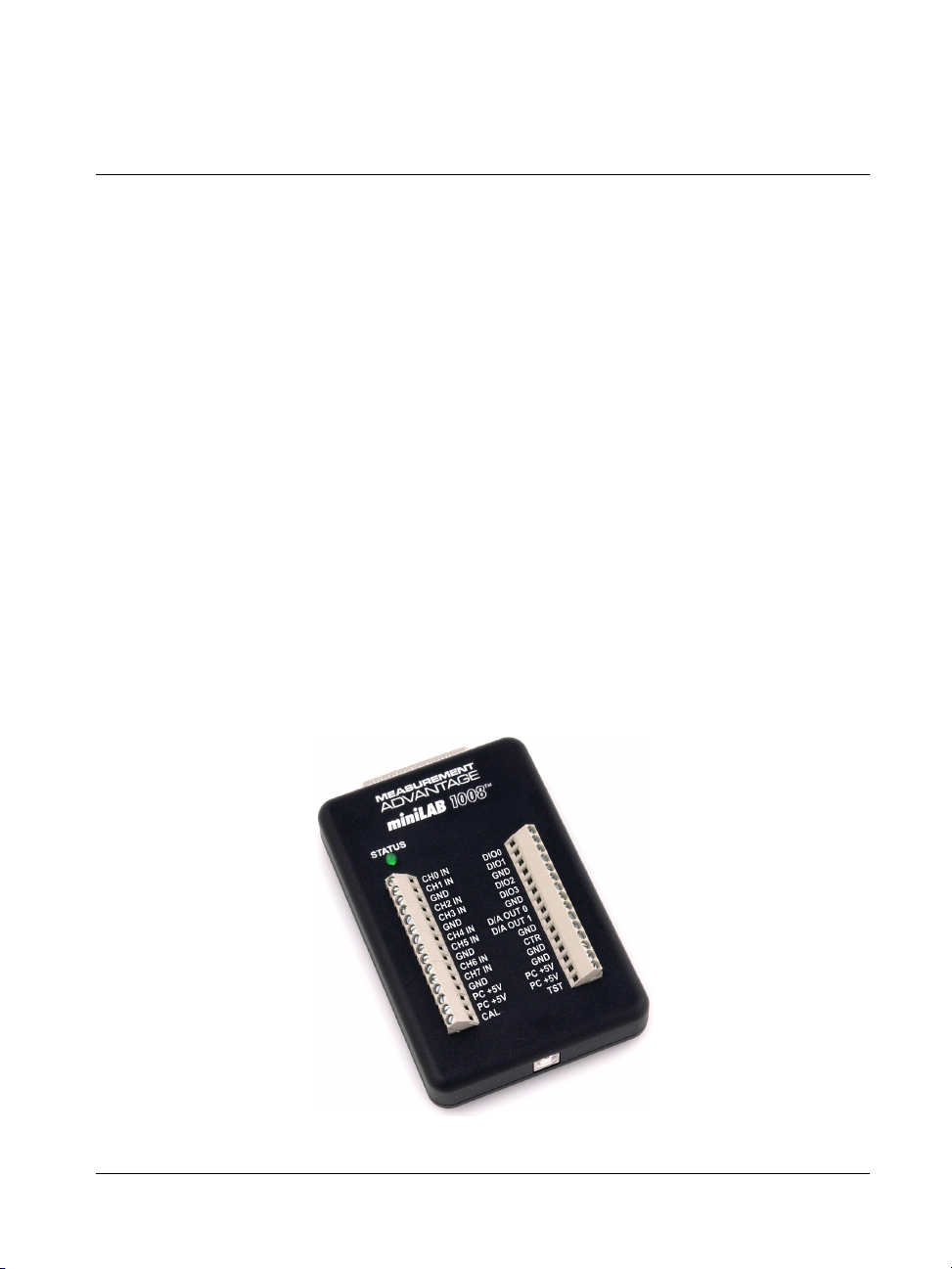
The miniLAB 1008 is a USB 1.1 low-speed analog and digital I/O device that is
supported under Microsoft® Windows® 98 (2
and Window XP. miniLAB 1008 is compatible with both USB 1.1 and USB 2.0 ports.
The miniLAB 1008 features eight 12-bit analog input signal connections and up to
28 digital I/O connections. It is powered by the +5 volt USB supply. No external power
is required.
Two screw terminals rows provide connections for eight analog inputs, two 10-bit
analog outputs, four digital I/O lines, and one 32-bit external event counter. You can
configure the analog connections with software as either four single-ended or
eight differential channels. All analog connections terminate at the screw terminals.
An on-board industry standard 82C55 programmable peripheral interface chip provides
24 digital I/O lines that terminate at a 37-pin connector.
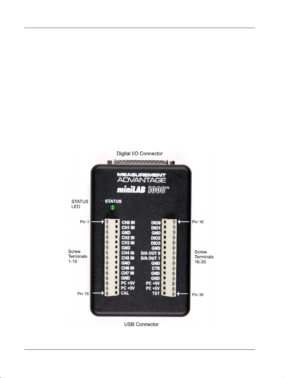
The miniLAB 1008 USB device is shown in Figure 1-1.
nd
edition), Windows ME, Windows 2000,
Figure 1-1. miniLAB 1008
1-1
Page 12
miniLAB 1008 User's Guide Introducing the miniLAB 1008
A
A
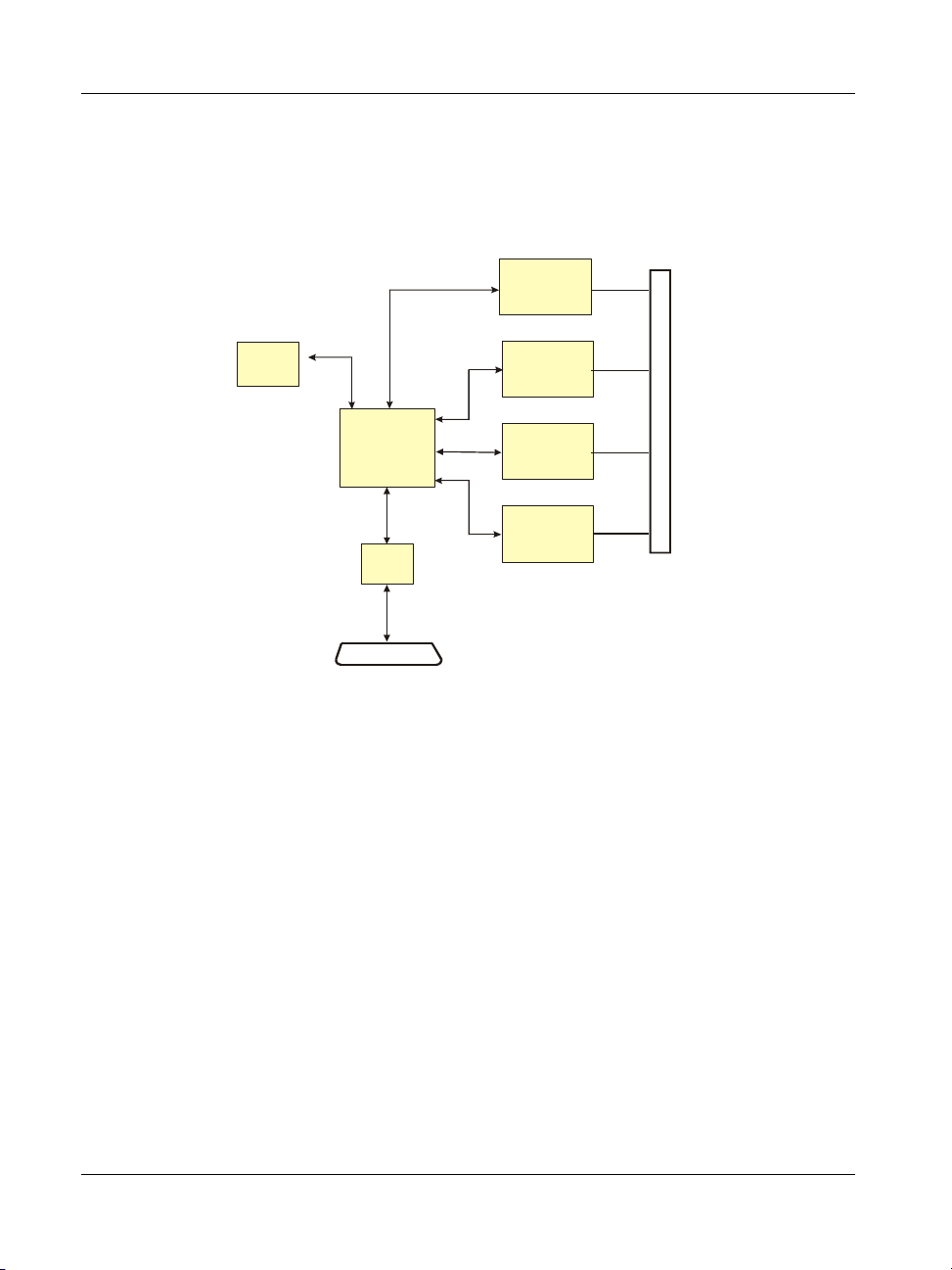
miniLAB 1008 block diagram
miniLAB 1008 functions are illustrated in the block diagram shown here.
Screw Terminal
I/O Conn ector
4 Auxillary
DIO Bits
USB1.1
Compliant
Interface
Figure 1-2. miniLAB 1008 Functional Block Diagram
Software features
The miniLAB 1008 ships with the following software:
InstaCal installation, calibration, and test utility
TracerDAQ
™
strip chart/data logging and scope virtual instruments
USB
Microcontroller
82C55
DIO
DB37 I/O Connector
12-Bit
nalog Inpu t
8 SE / 4 Diff.
10-Bit
nalog Output
2 chann el
32-Bit Event
Counter
Universal Library™ data acquisition and control programming library
SoftWIRE® for VS .NET (fully-functional, limited time license)
SoftWIRE for VB6 (fully-functional, limited time license)
SoftWIRE MCC DAQ Components for .NET
SoftWIRE MCC DAQ Controls for VB6
Universal Library for LabVIEW™
In addition, an OEM software library is available to download from our web site.
1-2
Page 13
miniLAB 1008 User's Guide Introducing the miniLAB 1008
InstaCal
InstaCal is a complete installation, calibration, and test program for MCC data
acquisition and control hardware. Complete with extensive error checking, InstaCal
guides you through the installation and setup of your miniLAB 1008, and creates the
hardware configuration file for use by your programming or application software.
InstaCal provides the easiest way to calibrate and configure the miniLAB 1008.
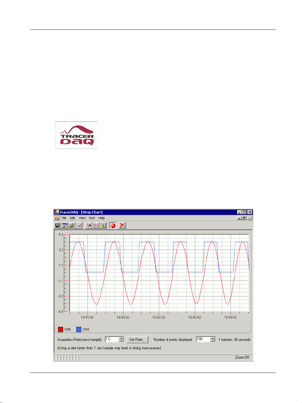
TracerDAQ
TracerDAQ is installed with InstaCal. TracerDAQ includes fully-
configured and ready-to-run virtual instruments, such as a strip chart
and oscilloscope. You can use these instruments to plot data from
the miniLAB 1008 directly to your computer. Your measurements
are plotted as they are acquired. Once acquired, you can save the measurement data to a
text or Excel file, and capture the graphical display as a bitmap. TracerDAQ online help
includes a quick start exercise that explains how to acquire and display data. You can
launch TracerDAQ from InstaCal’s
In the example below, the TracerDAQ virtual strip chart displays data acquired from two
channels on the miniLAB 1008.
Applications menu.
1-3
Page 14

miniLAB 1008 User's Guide Introducing the miniLAB 1008
With TracerDAQ, you can perform the following tasks:
specify sources of data from available hardware (eight data sources for the strip
chart, and four data sources for the scope)
save configurations for future use
use markers to analyze data points individually or comparatively
zoom in on specific data points on the graphical display
customize the colors, text, and data that you want to display
save data to a text file or Microsoft Excel file
capture and save the strip chart or scope display as a bitmap file
TracerDAQ technical support is FREE, and is available only via email at
freesupport@mccdaq.com
.
Universal Library
The Universal Library is a programmer’s library that you can use to write programs
from the full range of 32-bit Windows programming languages. The Universal Library is
a complete set of I/O libraries and drivers for all Measurement Computing boards and
for all Windows-based languages. When using the Universal Library, you can switch
boards or even programming languages, and the syntax remains constant.
The Universal Library provides the easiest way to program the miniLAB 1008. If you
are planning to write programs, or would like to run the example programs for Visual
Basic
or any other language, refer to the Universal Library User’s Guide and the
Universal Library Function Reference. These documents are copied to
C:\MCC\Documents\ SM UL USER'S GUIDE.pdf and C:\MCC\Documents\ SM UL
FUNCTION REF.pdf by default during installation.
The Universal Library functions that are supported by the miniLAB 1008 are listed in
the "miniLAB 1008" section of the "Analog Input Boards" chapter in the Universal
Library User’s Guide. Example programs that demonstrate how to use the Universal
Library functions are included with the Universal Library software package.
SoftWIRE Graphical Programming limited time license
A fully-functional, limited-time license version of SoftWIRE is
included with your purchase of the miniLAB 1008. SoftWIRE
is a graphical programming extension for Microsoft Visual Studio®. Like LabVIEW,
SoftWIRE gives you the power to create programs graphically without having to write in
BASIC or C.
1-4
Page 15
miniLAB 1008 User's Guide Introducing the miniLAB 1008
Unlike LabVIEW, which is proprietary, SoftWIRE is based upon Visual Studio. You
can easily create new icon function blocks, write a few lines of code, or add any library,
driver, or component written for Visual Studio. And unlike LabVIEW, there are no
runtime license fees. You can freely distribute the programs you create.
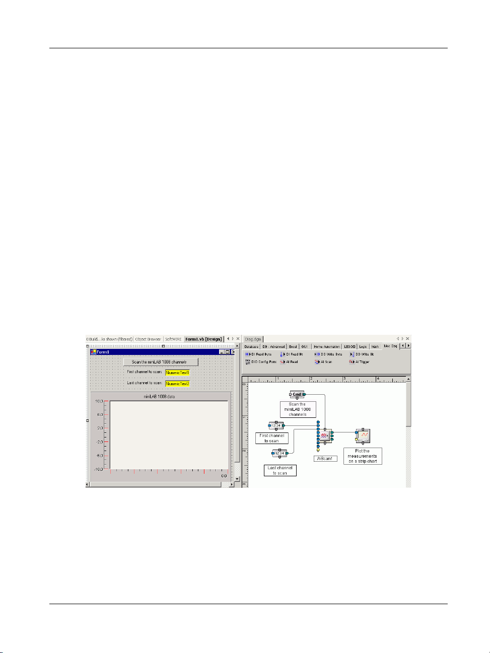
SoftWIRE MCC DAQ Components for .NET
SoftWIRE MCC DAQ Components for .NET is a collection of data acquisition
components that you can use to develop custom applications with SoftWIRE for Visual
Studio .NET.
With these components, you can develop programs that read from and write to your
miniLAB 1008 analog and digital channels. Example programs that demonstrate how to
use the data acquisition components are included with the SoftWIRE MCC DAQ
Components for .NET software package.
In the following program, the SoftWIRE AI Scan component is configured to scan a
range of channels on the miniLAB 1008 and display the measurements on a strip chart.
The form on the left (
when you run the program. The Diagrammer pane on the right (Diag.dgm) is where you
build the program by adding components and wiring their I/O pins together
Form1) is where you arrange the graphical components for display
The following image shows Form1 after you enter the range of channels to scan and run
the program.
1-5
Page 16

miniLAB 1008 User's Guide Introducing the miniLAB 1008
SoftWIRE MCC DAQ Controls for VB6
SoftWIRE Graphical Programming MCC DAQ Controls for VB6 is a collection of
SoftWIRE data acquisition controls that you can use to develop custom applications
with SoftWIRE 3.1 and Visual Basic 6.0.
With these controls, you can develop programs that read from and write to your
miniLAB 1008 analog and digital channels. Example programs that demonstrate how to
use the data acquisition controls are included with the SoftWIRE MCC DAQ Controls
for VB6 software package.
Universal Library for LabVIEW
The Universal Library for LabVIEW software is a collection of Universal Library VIs
that you can use to create LabVIEW programs.
With MCC’s Universal Library for LabVIEW, you can construct your own LabVIEW
programs using Universal Library VIs to control your miniLAB 1008.
The Universal Library for LabVIEW User’s Guide is copied to C:\MCC\Documents\
SM-UL-LabVIEW.pdf by default during installation. Example programs that demonstrate
how to use UL for LabVIEW VIs are included with the Universal Library for LabVIEW
software package.
1-6
Page 17

miniLAB 1008 User's Guide Introducing the miniLAB 1008
PMD-LS Series OEM Software Library and documentation are available
The OEM software provides source code that you can use to develop your own custom
applications that are independent of InstaCal or the Universal Library. You can develop
programs in any environment that supports 32-bit DLL’s, such as Microsoft's Visual
C/C++ and Visual Basic®.
You can download the PMD-LS Series OEM Software Library from our web site at
www.mccdaq.com/PMDregistration.asp.
Installation instructions and function explanations for the OEM Software Library are
included in the PMD-LS Series OEM Software Library User's Guide (available on our
web site at www.mccdaq.com/PDFmanuals/PMD-LS-Library.pdf).
Connecting a miniLAB 1008 to your computer is easy
Installing a data acquisition device has never been easier.
The miniLAB 1008 relies upon the Microsoft Human Interface Driver (HID) class.
The HID class ships with every copy of Windows that is designed to work with
USB ports. We use the Microsoft HID because it is a standard, and its performance
delivers full control and maximizes data transfer rates for your miniLAB 1008. No
third-party device driver is required.
The miniLAB 1008 is plug-and-play. There are no jumpers to position, DIP
switches to set, or interrupts to configure.
You can connect the miniLAB 1008 before or after you install the software, and
without powering down your computer first. When you connect an HID to your
system, your computer automatically detects it and configures the necessary
software. You can connect and power multiple HID peripherals to your system
using a USB hub.
You can connect your system to various devices using a standard four-wire cable.
The USB connector replaces the serial and parallel port connectors with one
standardized plug and port combination.
You do not need a separate power supply module. The USB automatically delivers
the electrical power required by each peripheral connected to your system.
Data can flow two ways between a computer and peripheral over USB connections.
Make sure that you have the latest Windows Updates installed for your USB driver,
particularly "XP Hotfix KB822603". Refer to the section "Be sure you are using the
latest system software" on page 2-3 for more information.
1-7
Page 18

Page 19

Installing the miniLAB 1008
What comes with your miniLAB 1008 shipment?
As you unpack your miniLAB 1008 device, verify that the following components are
included:
Hardware
miniLAB 1008 device
Chapter 2
USB cable
2-1
Page 20

miniLAB 1008 User's Guide Installing the miniLAB 1008
Software
The Personal Measurement Device installation CD contains the following software:
InstaCal installation, calibration, and test utility
TracerDAQ virtual instruments
Universal Library data acquisition and control
programming library
SoftWIRE for VS .NET (fully-functional,
limited time license)
SoftWIRE for VB6 (fully-functional, limited time license)
SoftWIRE MCC DAQ Components for .NET
SoftWIRE MCC DAQ Controls for VB6
Universal Library for LabVIEW
Documentation (PDF format)
Universal Library User's Guide, and Universal Library Function Reference
(installed with the Universal Library software)
2-2
Page 21

miniLAB 1008 User's Guide Installing the miniLAB 1008
Universal Library for LabVIEW User's Guide (installed with the Universal Library
for LabVIEW software)
Unpacking the miniLAB 1008
The miniLAB 1008 is shipped in an antistatic container to prevent damage by an
electrostatic discharge. To avoid such damage, perform the following procedure when
unpacking and handling your board:
1.
Before opening the antistatic container, ground yourself with a wrist-grounding
strap or by holding onto a grounded object (such as the computer chassis).
2.
Touch the antistatic container to the computer chassis before removing the
miniLAB 1008 from the container.
3.
Remove the miniLAB 1008 from the container.
If any components are missing or damaged, notify Measurement Computing Corporation
immediately by phone, fax, or e-mail:
Phone: 508-946-5100 and follow the instructions for reaching Tech Support.
Fax: 508-946-9500 to the attention of Tech Support
Email: techsupport@measurementcomputing.com
Be sure you are using the latest system software
Before you connect the miniLAB 1008 and install the software, make sure that you are
using the latest versions of the following software:
USB driver
Microsoft Data Access Components
.NET Framework
2-3
Page 22

miniLAB 1008 User's Guide Installing the miniLAB 1008
USB driver
Before installing the miniLAB 1008, download and install the latest Microsoft Windows
updates. In particular, when using Windows XP, make sure you have XP Hotfix
KB822603 installed. This update is intended to address a serious error in Usbport.sys
when you operate a USB device. You can run Windows Update or download the update
from www.microsoft.com/downloads/details.aspx?familyid=733dd867-56a0-4956-b7fe-
e85b688b7f86&displaylang=en. For more information, refer to the Microsoft
Knowledge Base article "Availability of the Windows XP SP1 USB 1.1 and 2.0 update".
This article is available at support.microsoft.com/?kbid=822603
.
Microsoft Data Access Components (MDAC)
TracerDAQ requires Microsoft Data Access Components (MDAC), version 2.6 or later.
MDAC contains the Microsoft SQL Server™ OLE DB provider, and the ODBC driver.
To determine what version of MDAC is installed on your computer, refer to the
Microsoft Knowledge Base article 301202 "How To: Check for MDAC Version". This
article is available at http://support.microsoft.com/default.aspx?scid=kb;en-
us;301202&Product=mdac.
You can download the latest version of the Microsoft Data Access components at
http://msdn.microsoft.com/data/downloads/updates/default.aspx#MDACDownloads
.
.NET Framework
TracerDAQ requires the Microsoft .NET Framework to be installed. The Microsoft
.NET Framework is a component of the Microsoft Windows operating system that is
used to build and run web-based applications, smart client applications, and web
services. To learn more about the.NET Framework, go to Microsoft’s .NET
Framework’s home page at msdn.microsoft.com/netframework
When you install TracerDAQ, the installation program searches your computer for the
.NET Framework software. If the .NET Framework is not detected, the dialog shown
below opens with the location to download the .NET Framework from. You must install
the .NET Framework in order to run TracerDAQ.
2-4
.
Page 23

miniLAB 1008 User's Guide Installing the miniLAB 1008
Installing the miniLAB 1008
To connect the miniLAB 1008 to your system, turn your computer on, and connect the
USB cable to a USB port on your computer or to an external USB hub that is connected
to your computer. The USB cable provides power and communication to the miniLAB
1008.
When you connect the miniLAB 1008 for the first time, a Found New Hardware popup
balloon (Windows XP) or dialog (other Windows version) displays as the miniLAB
1008 is detected by your computer.
A number of Found New Hardware balloons or dialogs appear after the first closes that
identify the miniLAB 1008 as a USB Human Interface Device. The last balloon or
dialog to appear indicates that the miniLAB 1008 is installed and ready to use.
After the last balloon or dialog closes, the LED on miniLAB 1008 should flash and then
remain lit. This indicates that communication is established between the miniLAB 1008
and your computer.
Caution! Do not disconnect any device from the USB bus while the computer is
communicating with the miniLAB 1008, or you may lose data and/or your ability
to communicate with the miniLAB 1008.
If the LED turns off
If the LED is illuminated but then turns off, the computer has lost communication with
the miniLAB 1008. To restore communication, disconnect the USB cable from the
computer, and then reconnect it. This should restore communication, and the LED
should turn back on.
Installing the software
To install any of the software packages on the Personal Measurement Device CD,
perform these initial steps:
1.
Close all applications you have running.
2.
Insert the Personal Measurement Device CD into your CD drive.
If you have the auto-run feature enabled on your computer, the
Computing CD installation dialog opens.
2-5
Measurement
Page 24

miniLAB 1008 User's Guide Installing the miniLAB 1008
If the auto-run feature is not enabled on your computer, use Explorer to navigate
to the root of the CD drive, and double-click on the
Measurement Computing CD dialog opens.
program. The
Follow the procedures below to install one or more of the software packages
available from this dialog.
Installing InstaCal, TracerDAQ, and the Universal Library
InstaCal and the Universal Library are required to run the Universal Library for
LabVIEW, MCC DAQ Components for .NET and MCC DAQ Controls for VB6.
To install InstaCal, TracerDAQ, and the Universal Library, follow the procedure below.
1.
Click on the
InstaCal, TracerDAQ, and Universal Library button.
A Welcome dialog opens.
2.
Click on the
Next button.
An Installation Options dialog opens.
3.
Make sure the Windows Universal Library and InstaCal and TracerDAQ check
boxes are selected, and click on the
Next button.
2-6
Page 25

miniLAB 1008 User's Guide Installing the miniLAB 1008
TracerDAQ requires the .NET Framework
If your PC doesn’t have the .NET Framework installed, the TracerDAQ checkbox may
not be selected. The following dialog opens if the .NET Framework is not installed and
you click in the checkbox to override the default (unchecked) setting of the TracerDAQ
checkbox.
Click OK to continue the installation. Before running TracerDAQ, use your browser to
download and install the .NET Framework from the web address specified on the dialog.
4. If you are not installing any other software on the CD, restart your computer.
If you want to install other software, you can wait to reboot the computer until after
that software is installed.
Installing Universal Library for LabVIEW
You must install InstaCal before you install the Universal Library for LabVIEW. Refer
to "Installing InstaCal, TracerDAQ, and the Universal Library" on page 2-6.
The Universal Library for LabVIEW installation program also checks to see if
LabVIEW is installed on your computer. If a licensed copy of LabVIEW is not installed,
the Universal Library for LabVIEW installation program exits.
To install UL for LabVIEW, follow the procedure below.
1.
Click on the
Universal Library for LabVIEW button.
A Welcome dialog opens.
2.
Click on the
Next button, and follow the installation instructions as prompted.
2-7
Page 26
miniLAB 1008 User's Guide Installing the miniLAB 1008
Installing SoftWIRE Graphical Programming
SoftWIRE 4.2 for Visual Studio .NET is required to use MCC DAQ Components for
.NET. You must install Visual Studio .NET before you install SoftWIRE for Visual
Studio .NET.
If you are interested in exploring graphical programming, but do not own a copy of
Visual Studio, you can purchase a copy of Visual Basic .NET for under $99. To learn
where, and to learn more about SoftWIRE Graphical Programming, call our Technical
Sales Engineers at 508-946-5100 x2.
SoftWIRE 3.1 for Visual Basic® 6.0 is required to use MCC DAQ Controls for VB6.
You must install Visual Basic 6.0 before you install SoftWIRE 3.1 for Visual Basic 6.
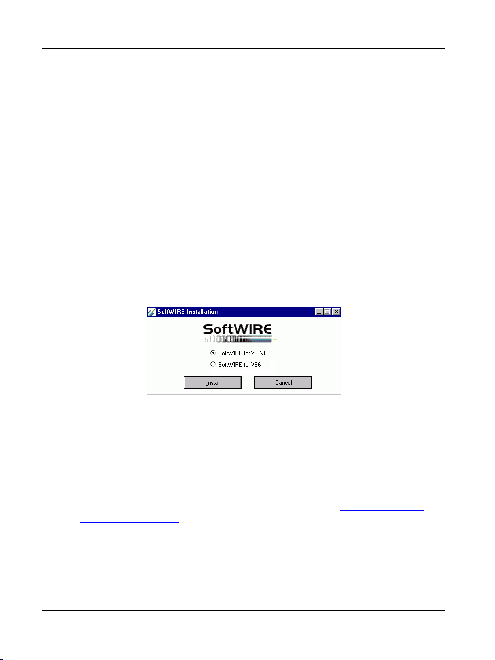
To install SoftWIRE 4.2 for VS .NET or SoftWIRE 3.1 for VB6, follow the procedure
below.
1. Click on the
2.
Click to select the SoftWIRE version to install, and then click on the Install button.
3.
Follow the installation instructions as prompted.
SoftWIRE button. A SoftWIRE Installation dialog opens.
Installing SoftWIRE MCC DAQ Components or Controls
You must install SoftWIRE for Visual Studio .NET before you install SoftWIRE MCC
DAQ Components for .NET. You must install SoftWIRE 3.1 for Visual Basic 6.0 before
you install SoftWIRE MCC DAQ Controls for VB 6. Refer to "Installing SoftWIRE
Graphical Programming" on page 2-8 for instructions.
You must install the Universal Library before you install either SoftWIRE MCC DAQ
Components for .NET or SoftWIRE MCC DAQ Controls for VB6. Refer to "Installing
InstaCal, TracerDAQ, and the Universal Library" on page 2-6 for instructions.
2-8
Page 27

miniLAB 1008 User's Guide Installing the miniLAB 1008
To install SoftWIRE MCC DAQ Components or SoftWIRE MCC DAQ Controls,
follow the procedure below.
1. Click on the
SoftWIRE DAQ Components button.
A SoftWIRE DAQ Components Installation dialog opens.
2.
Click to select either SoftWIRE MCC DAQ Components for VS .NET, or SoftWIRE
MCC DAQ Controls for VB6
3.
Follow the installation instructions as prompted.
, and click on the Install button.
Setting up the miniLAB 1008 with InstaCal
Use InstaCal to configure the number of analog input channels (eight single-ended or
four differential) on the miniLAB 1008, and also to change the custom serial number.
Adding the miniLAB 1008 to the InstaCal configuration file
To run InstaCal and add the miniLAB 1008 to its configuration file, follow these steps.
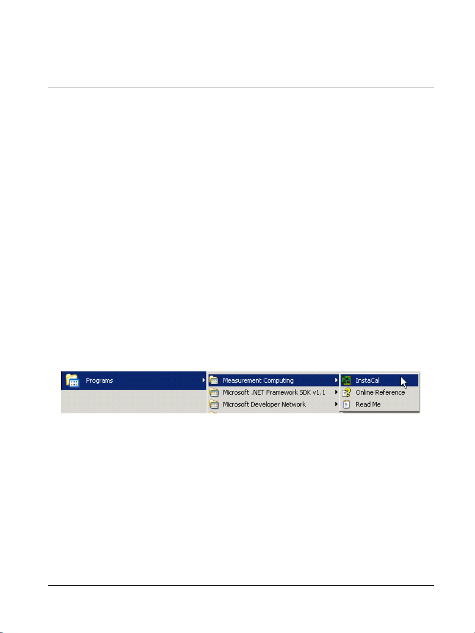
1.
Click on
Start > Measurement Computing > InstaCal to launch InstaCal.
A Plug and Play Board Detection dialog opens in front of the InstaCal main form.
The
Plug and Play Board Detection dialog lists the miniLAB 1008, and only
opens when you first install or if you reinstall the miniLAB 1008.
2-9
Page 28
miniLAB 1008 User's Guide Installing the miniLAB 1008
The serial number shown in the dialog is a custom number automatically assigned
by InstaCal when you install the miniLAB 1008.
If InstaCal does not detect the miniLAB 1008
If the Plug and Play Board Detection dialog does not display, go to "If the miniLAB
1008 is not detected by InstaCal" on page 2-10.
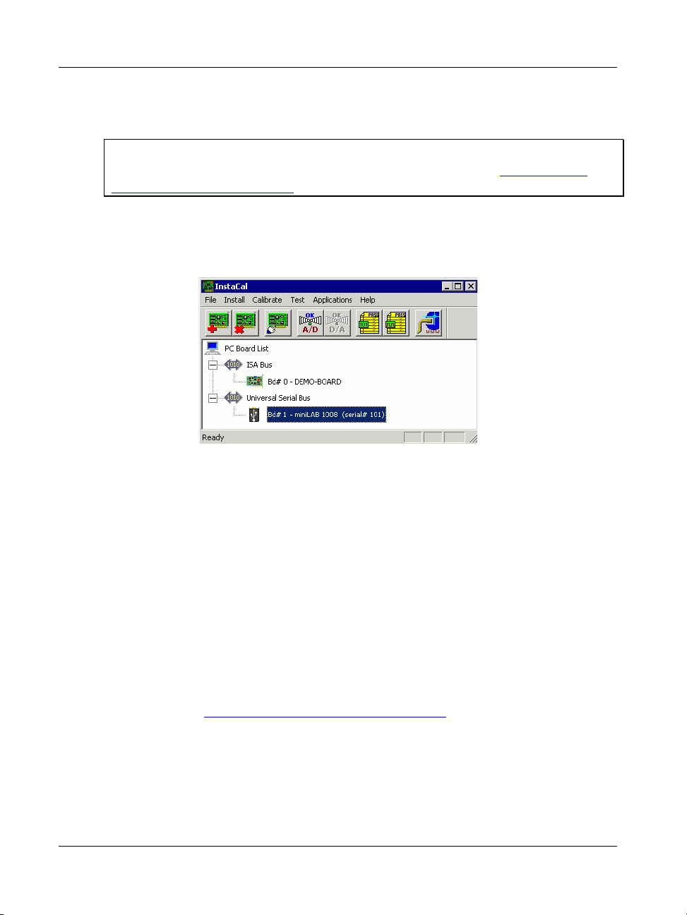
2. Leave the check box next to the miniLAB 1008 item checked, and click OK.
The dialog closes, and the miniLAB 1008 is added to the PC Board List on the
InstaCal main form.
If the miniLAB 1008 is not detected by InstaCal
If the
Plug and Play Board Detection dialog does not appear, exit InstaCal (Exit
option on the
and that you are running a supported operating system (Microsoft® Windows® 98
nd
edition), Windows ME, Windows 2000, or Window XP). Then, run InstaCal
(2
File menu). Make sure that you connected the USB cable properly,
again.
If your USB connection is good, and you are running a supported operating system,
but InstaCal still does not detect the miniLAB 1008, notify Measurement
Computing Corporation by phone, fax, or email:
o
Phone: 508-946-5100 and follow the instructions for reaching Technical
Support.
o
Fax: 508-946-9500 to the attention of Technical Support
o
Email: techsupport@measurementcomputing.com
2-10
Page 29
miniLAB 1008 User's Guide Installing the miniLAB 1008
Configuring the miniLAB 1008 with InstaCal
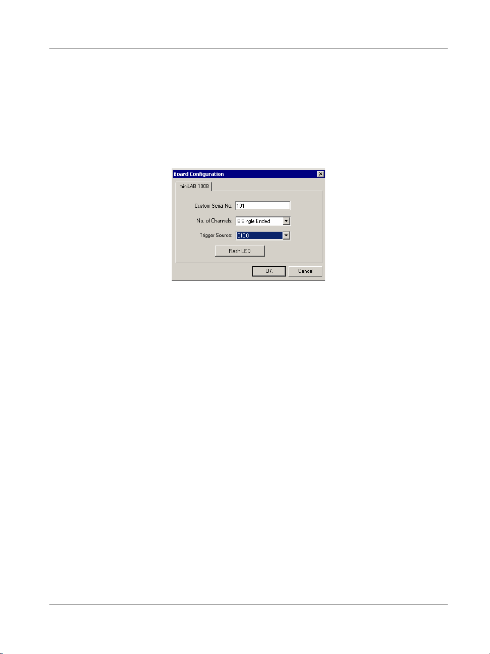
To change the configuration of the miniLAB 1008, follow the steps below.
1. Double-click on the miniLAB 1008 item listed below
Universal Serial Bus.
The Board Configuration dialog opens.
Pull down the No. of Channels: list box and select either 4 Differential or 8 Single
Ended as the analog input configuration.
Pull down the
Trigger Source: list box and select the digital bit (DIO0 to DIO4) to
use as the trigger source.
To change the custom serial number assigned by InstaCal to the miniLAB 1008 —
as part of a numbering scheme to keep track of multiple units in the field, for
example — enter a number from 1 to 255 in the
Custom Serial No: text box. The
miniLAB 1008 stores its serial number in its memory, and retains the serial number
even when it is powered down.
If you installed more than one miniLAB 1008, you can click the Flash LED button
to identify the miniLAB 1008 device that you are configuring. Clicking on this
button causes the LED of the selected miniLAB 1008 to blink.
2.
Click on the
3.
When you are done using InstaCal, select Exit from the File menu to close InstaCal.
OK button to close the dialog.
2-11
Page 30

Page 31
Getting Started with TracerDAQ
TracerDAQ is a set of virtual instruments that you can use to acquire and display analog
data from the miniLAB 1008.
This chapter details how you acquire data from the miniLAB 1008, and plot the data on
the TracerDAQ strip chart. The following exercise helps get you started with the
TracerDAQ strip chart by showing you how to:
Launch TracerDAQ from InstaCal
Select the hardware and channels to use as your data source
Log the data to a file
Plot the data on TracerDAQ's strip chart
Launching TracerDAQ from InstaCal
Measurement Computing’s InstaCal program shares configuration information with
TracerDAQ. To start TracerDAQ from InstaCal, follow these steps.
Chapter 3
1. Click on Start >Programs>Measurement Computing>InstaCal to launch the
InstaCal application.
The InstaCal main form opens.
3-1
Page 32

miniLAB 1008 User's Guide Getting Started with TracerDAQ
2.
From the PC Board List, select the miniLAB 1008 item.
3.
Select TracerDAQ from the Applications menu to launch TracerDAQ.
The first time you launch TracerDAQ, the strip chart's Data Source Setup dialog
opens by default. Each successive time you launch TracerDAQ, the
Setup dialog for either the strip chart or scope opens, depending on which
Data Source
application you last ran.
TracerDAQ's virtual instruments are accessed from the View menu
You can launch each virtual instrument from TracerDAQ's pull-down View menu.
When TracerDAQ is launched from InstaCal, the Board drop-down list for the first
plot shows the name of the miniLAB 1008 that you selected in InstaCal.
3-2
Page 33

miniLAB 1008 User's Guide Getting Started with TracerDAQ
Use this dialog to set up the miniLAB 1008 as the data source used by the strip chart.
Selecting the channels to use for data
For this exercise, you are going select channels 0 and 3 as the data source you want to
acquire and plot. For each channel, you can configure the following options:
the A/D range of data to acquire
the name that appears on the strip chart legend to identify the data
the plot line to use for the data
To configure these options, do the following
Configuring channel 0
To configure the miniLAB 1008's channel 0 as part of the data source to acquire and
plot, follow the steps below.
1. Click to select the first Enabled check box. This enables a plot line to show on the
strip chart.
3-3
Page 34

miniLAB 1008 User's Guide Getting Started with TracerDAQ
2. In the Name text box, enter CH0. The name you enter shows on the strip chart's
legend.
3. In the Board Channel number entry box, enter 0, or click the numeric up/down
control arrows to select the number.
4. From the Range list box, select BIP10Volts.
Configuring channel 3
To configure the miniLAB 1008's channel 3 as part of the data source to acquire and
plot, follow the steps below.
1. Click to select the second
2. In the Board list box, click the down arrow and select the miniLAB 1008.
3. In the Name text box enter CH3. This name also shows on the strip chart's legend.
Enabled check box.
3-4
Page 35

miniLAB 1008 User's Guide Getting Started with TracerDAQ
4. In the Board Channel number entry box, enter 3, or click the numeric up/down
control arrows to select the number.
5. From the Range list box, click the down arrow and select BIP10Volts.
The Data Source Setup dialog should look like the one below:
6. Click the OK button at the bottom of the dialog.
The Data Source Setup dialog closes, and the TracerDAQ – [Strip Chart] form
becomes active, as shown below.
Use the TracerDAQ – [Strip Chart] form to set up your data log file, and to start
acquiring and plotting miniLAB 1008 data.
3-5
Page 36

miniLAB 1008 User's Guide Getting Started with TracerDAQ
Setting up a data log file
You can log all of your data to a text file or to a Microsoft Excel spreadsheet using the
TracerDAQ strip chart's Data Logging Options dialog. When you log data, all of the
data acquired since the scan began is saved to a file that you specify.
This exercise shows you how to specify a text file used to log data. To do this, do the
following:
1. From the
TracerDAQ – [Strip Chart] form, click on the icon.
The Data Logging Options dialog opens.
Use the options on the Text File tab to specify the name and location of the text file
used to log data.
2.
Click in the
3.
Click the Browse button to open a Save As dialog.
Log to text file check box to log data to a text file.
3-6
Page 37

miniLAB 1008 User's Guide Getting Started with TracerDAQ
4.
In the Save As dialog, enter a name in the File Name text box, and navigate to the
location where you want to save the text file.
TracerDAQ creates the file if it does not already exist.
5.
Click the
Save button to close the Save As dialog.
The Data Logging Options dialog returns with the name and location you
specified. In this example, the data is saved to
miniLAB 1008 data.txt in the root
directory of the C:\ drive.
6. Click the OK button to save your text file settings. The Data Logging Options
dialog closes, and you are returned to the TracerDAQ – [Strip Chart] form.
Plotting and logging data on the TracerDAQ strip chart
To start the scan and plot the acquired data from channels 0 and 3 on the TracerDAQ –
[Strip Chart]
The TracerDAQ strip chart immediately begins to plot and log the data as it is acquired.
form, click on the icon.
3-7
Page 38

miniLAB 1008 User's Guide Getting Started with TracerDAQ
TracerDAQ strip chart continues to acquire, plot, and log data until you click on the
icon.
An example of a strip chart data log file is shown below.
To stop acquiring data, click on the icon. To exit TracerDAQ, select Exit from the
TracerDAQ – [Strip Chart] form’s File menu.
3-8
Page 39

miniLAB 1008 User's Guide Getting Started with TracerDAQ
With TracerDAQ's virtual instruments, you can also perform the following data
acquisition functions:
save data source information for later use
set up a trigger to control when you acquire data
customize the color of plot lines, grid lines, background areas, text, and other visual
elements
use cursors to analyze data points individually or comparatively
zoom in on specific data points on the graphical display
save currently visible data to text and/or Excel files
capture and save the virtual display as a bitmap file
email data from within the application
You can also perform the following tasks with the strip chart:
set the acquisition rate to acquire data
view data as it is acquired ("live" mode), or view all data acquired during a
TracerDAQ session ("history" mode)
isolate specific data for analysis
You can also perform the following tasks with the scope:
acquire single-sweep or continuous-sweep data
set vertical scaling options (volts/division and millivolts/division), and horizontal
scaling options (seconds/division and milliseconds/division)
display minimum and maximum value markers
display period and frequency values
For detailed information about all of the data acquisition features provided by each
virtual instrument, refer to the TracerDAQ - Online Help. To view the online help, select
TracerDAQ Help from the Help menu of each TracerDAQ virtual instrument.
3-9
Page 40

Page 41

Chapter 4
Functional Details
Theory of operation - analog input acquisition modes
The miniLAB 1008 can acquire analog input data in three different modes – software
paced, continuous scan, and burst scan.
Software paced mode
In software paced mode, the miniLAB 1008 gathers data in a single acquisition or as a
group of single acquisitions. An analog-to-digital conversion is initiated with a software
command, and the single data point result is returned to the host. This operation may be
repeated until the required number of samples is obtained for the channel (or channels)
in use. Software pacing is limited by the 20 mS round-trip requirement of a USB
interrupt-type endpoint operation. This yields a maximum throughput in software paced
mode of 50 S/s.
Continuous scan mode
In continuous scan mode, the miniLAB 1008 gathers data in a single-channel or multichannel sequence. This sequence converts, transfers, and stores data to a user buffer
until the scan is stopped. In this mode, digitized data is continuously written to an onboard FIFO buffer. This FIFO is serviced in blocks as the data is transferred from the
miniLAB 1008 to the user buffer in the host PC.
The maximum continuous scan rate of 1.2 kS/s is an aggregate rate. The total acquisition
rate for all channels cannot exceed 1.2 kS/s. You can acquire data from one channel at
1.2 kS/s, two channels at 600 S/s and four channels at 300 S/s. You can start a
continuous scan with either a software command or with an external hardware trigger
event.
Burst scan mode
In burst scan mode, the miniLAB 1008 gathers data using the full capacity of its 4K
sample FIFO buffer. You can initiate a single acquisition sequence of one or more
channels by either a software command or an external hardware trigger. The captured
data is then read from the FIFO and transferred to a user buffer in the host PC.
4-1
Page 42
miniLAB 1008 User's Guide Functional Details
Since the data is acquired at a rate faster than it can be transferred to the host, burst scans
are limited to the depth of the on-board memory. As with continuous mode, the
maximum sampling rate is an aggregate rate. Consequently, the maximum burst mode
rates are 8 kS/s, 4 kS/s and 2 kS/s for one, two and four channels, respectively.
External components
The miniLAB 1008 has the following external components, as shown in Figure 4-1.
USB connector
Status LED
Digital I/O connector
Screw terminal banks (2)
Figure 4-1. miniLAB 1008
4-2
Page 43

miniLAB 1008 User's Guide Functional Details
USB connector
The USB connector is located on the bottom edge of the miniLAB 1008. This connector
provides +5 V power and communication. The voltage supplied through the USB
connector is system-dependent, and may be less than 5 V. No external power supply is
required.
Caution! The USB +5 V pin on the DB37 connector is an output. Do not connect an
external 5 V supply or you may damage the miniLAB 1008 and possibly the
computer.
Status LED
The STATUS LED on the front of the miniLAB 1008 indicates the communication
status. It uses up to 5 milliamperes (mA) of current and cannot be disabled.
explains the function of the miniLAB 1008 LED.
Table 4-1. LED Illumination
LED Illumination Indication
Steady The miniLAB 1008 is connected to a computer or external USB hub.
Blinks continuously Data is being transferred.
Blinks three times
Blinks at a slow rate
Initial communication is established between the miniLAB 1008 and
the computer.
The analog input is configured for external trigger. The LED stops
blinking and illuminates steady green when the trigger is received.
Table 4-1
Digital I/O connector and pin out
Digital I/O connections are made to the DB37 connector on the top edge of the miniLAB
1008. This connector provides connections for 24 digital lines (Port A0 to Port C7), six
ground connections, and +5 V USB power out. Refer to and Table 4-2 for the
DB37 connector pin out.
Digital connections (Port A0 through Port C7)
The 24 digital I/O pins (Port A0-A7, Port B0-B7 and Port C0-C7) are TTL-level
compatible. Each pin has a 47 kilohm (KΩ) pull-up resistor and is configured as an input
by default. If needed, the miniLAB 1008 can be factory configured to provide pull-down
resistors.
4-3
Figure 4-2
Page 44

miniLAB 1008 User's Guide Functional Details
Caution! Port A0 through Port C7 have no overvoltage/short circuit protection. Do not
exceed the voltage limits or you may damage the pin or the miniLAB 1008. To
protect these pins, you should use a series resistor.
37
19
20
1
Figure 4-2. DB37 Digital I/O Connector
Table 4-2. DB37 Connector Pin-Out
Pin Signal Name Pin Signal Name
1 n/c 20 USB +5 V
2 n/c 21 GND
3 Port B7 22 Port C7
4 Port B6 23 Port C6
5 Port B5 24 Port C5
6 Port B4 25 Port C4
7 Port B3 26 Port C3
8 Port B2 27 Port C2
9 Port B1 28 Port C1
10 Port B0 29 Port C0
11 GND 30 Port A7
12 n/c 31 Port A6
13 GND 32 Port A5
14 n/c 33 Port A4
15 GND 34 Port A3
16 n/c 35 Port A2
17 GND 36 Port A1
18 n/c 37 Port A0
19 GND
Refer to the "Digital connector cabling" section for descriptions of cables that are
compatible with the DB37 digital I/O connector.
Screw terminal wiring
The miniLAB 1008 has two rows of screw terminals. Each row has 15 connections. Pin
numbers are identified in Figure 4-3. The pins are labeled for eight-channel singleended mode operations.
4-4
Page 45
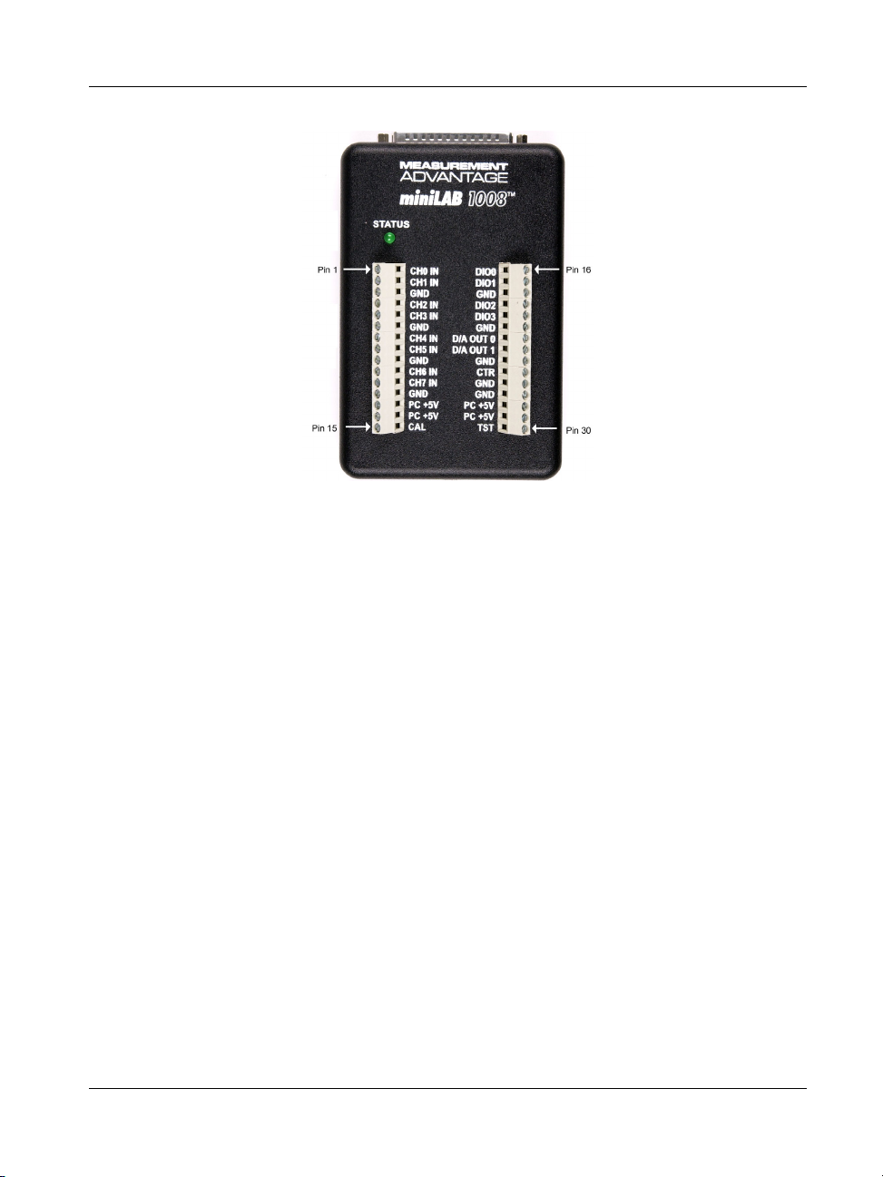
miniLAB 1008 User's Guide Functional Details
Figure 4-3. miniLAB 1008 Screw Terminals
Screw terminal – pins 1-15
The screw terminals on the left edge of the miniLAB 1008 (pins 1 to 15) provide the
following connections:
Eight analog input connections (
Four GND connections (
GND)
CH0 IN to CH7 IN)
One calibration terminal (CAL)
Two power connectors (
PC +5 V)
Screw terminal – pins 16-30
The screw terminals on the right edge of the miniLAB 1008 (pins 16 to 30) provide the
following connections:
Four digital I/O connections (
DIO0 to DIO3)
Two analog output connections (D/A OUT 0 to D/A OUT 1)
One external event counter connection (
CTR)
One testing and calibration terminal (TST)
Five ground connections (GND)
Two power connectors (
PC +5 V)
4-5
Page 46
miniLAB 1008 User's Guide Functional Details
Main connector and pin out
Connector type
Wire gauge range
4-channel differential
mode pin out
Note that the pins are
labeled for 8-channel
single-ended mode on the
miniLAB 1008.
8-channel
single-ended mode
pin out
Screw terminal
16 AWG to 26 AWG
CH0 IN HI 1
CH0 IN LO 2
GND 3
CH1 IN HI 4
CH1 IN LO 5
GND 6
CH2 IN HI 7
CH2 IN LO 8
GND 9
CH3 IN HI 10
CH3 IN LO 11
GND 12
PC +5 V 13
PC +5 V 14
CAL 15
16 DIO0
17 DIO1
18 GND
19 DIO2
20 DIO3
21 GND
22 D/A OUT0
23 D/A OUT1
24 GND
25 CTR
26 GND
27 GND
28 PC +5 V
29 PC +5 V
30 TST
Note that the pins are
labeled for 8-channel
single-ended mode on the
miniLAB 1008.
CH0 IN 1
CH1 IN 2
GND 3
CH2 IN 4
CH3 IN 5
GND 6
CH4 IN 7
CH5 IN 8
GND 9
CH6 IN 10
CH7 IN 11
GND 12
PC +5 V 13
PC +5 V 14
CAL 15
4-6
16 DIO0
17 DIO1
18 GND
19 DIO2
20 DIO3
21 GND
22 D/A OUT0
23 D/A OUT1
24 GND
25 CTR
26 GND
27 GND
28 PC +5 V
29 PC +5 V
30 TST
Page 47
miniLAB 1008 User's Guide Functional Details
Analog input terminals (CH0 In - CH7 In)
Connect up to eight analog input connections to the screw terminal connections labeled
CH0 In through CH7 In. Refer to the pinout diagrams on page 4-6 for the location of
these pins.
You can configure the analog input channels as eight single-ended channels or four
differential channels. When configured for differential mode, each analog input has
12-bit resolution. When configured for single-ended mode, each analog input has 11-bit
resolution, due to restrictions imposed by the A/D converter.
Single-ended configuration
When all of the analog input channels are configured for single-ended input mode, eight
analog channels are available. In single-ended mode, the input signal is referenced to
signal ground (GND). The input signal is delivered through two wires:
The wire carrying the signal to be measured connects to CH# IN.
The second wire connects to GND.
The input range for single-ended mode is ±10 V, max, with a gain of 2. No other gains
are supported in single-ended mode.
Figure 4-4
illustrates a typical single-ended measurement connection.
CH0
+
1.5
-
CH1 (differential configuration)
GND
Figure 4-4. Single-Ended Measurement Connection
Single-ended measurements using differential channels
To perform a single-ended measurement using differential channels, connect the voltage
to an analog input with an even-number, and ground the associated odd-numbered
analog input. This configuration is shown in Figure 4-4.
4-7
Page 48

miniLAB 1008 User's Guide Functional Details
Differential configuration
When all of the analog input channels are configured for differential input mode, four
analog channels are available. In differential mode, the input signal is measured with
respect to the low input.
The input signal is delivered through three wires:
The wire carrying the signal to be measured connects to CH<0, 2, 4, 6> IN. In
differential mode, the even numbered channels are considered HI inputs. Hence,
CH0 IN, CH2 IN, CH4 IN and CH6 IN are considered HI input channels.
The wire carrying the reference signal connects to CH<1, 3, 5, 7> IN. In differential
mode the odd numbered channels are considered the LO input. Hence, CH1 IN,
CH3 IN, CH5 IN and CH7 IN are considered LO input channels.
The third wire connects to GND.
When should you use a differential mode configuration?
Differential input mode is the preferred configuration for applications in noisy
environments, or when the signal source is referenced to a potential other than PC
ground.
A low-noise precision programmable gain amplifier (PGA) is available on differential
channels to provide gains of up to 20 and a dynamic range of up to 16-bits.
In differential mode, the following two requirements must be met for linear operation:
Any analog input must remain in the −10 V to +20 V range with respect to ground
at all times.
The maximum differential voltage on any given analog input pair must remain
within the selected voltage range.
The input [common-mode voltage + signal] of the differential channel must be in the
−10 V to +20 V range in order to yield a useful result.
For example, you input a 4 volt peak-to-peak (Vpp) sine wave to CHHI, and apply the
same sine wave 180° out of phase to CHLO. The common mode voltage is 0 V. The
differential input voltage swings from 4 V-(-4 V) = 8 V to -4 V-4 V = -8 V. Both inputs
satisfy the -10 V to +20 V input range requirement, and the differential voltage is suited
for the ±10 V input range (see Figure 4-5).
4-8
Page 49

miniLAB 1008 User's Guide Functional Details
+4V
CHHI
0V
-4V
Measured Signal
8V Differential
+4V
CHLO
-4V
+/-8V
Figure 4-5. Differential voltage example: common mode voltage of 0 V
If you increase the common mode voltage to 11 V, the differential remains at ±8 V.
Although the [common-mode voltage + signal] on each input now has a range of +7 V to
+15 V, both inputs still satisfy the -10 V to +20 V input requirement (see Figure 4-6).
+15V
CHHI
CHLO
+11V
+11V
+7V
8V Differential
+/-8V
Measured Signal
Figure 4-6. Differential voltage example: common mode voltage of 11 V
If you decrease the common-mode voltage to -7 V, the differential stays at ±8 V.
However, the solution now violates the input range condition of -10 V to +20 V. The
voltage on each analog input now swings from -3 V to -11 V. Voltages between -10 V
and -3 V are resolved, but those below -10 V are clipped (see Figure 4-7).
CHHI
CHLO
-3V
-7V
-11V
-3V
-7V
-11V
3V
8V Differential
+/-7V
Measured Signal
Figure 4-7. Differential voltage example: common mode voltage of -7 V
4-9
Page 50

miniLAB 1008 User's Guide Functional Details
Since the analog inputs are restricted to a −10 V to +20 V signal swing with respect to
ground, all ranges except ±20 V can realize a linear output for any differential signal
with zero common mode voltage and full scale signal inputs. The ±20 V range is the
exception. You cannot put −20 V on CHHI, and 0 V on CHLO, since this violates the
input range criteria. Table 4-3 shows some possible inputs and the expected results.
Table 4-3. Sample Inputs and Differential Results
CHHI CHLO Result
-20 V 0 V Invalid
-15 V +5 V Invalid
-10 V 0 V -10 V
-10 V +10 V -20 V
0 V +10 V -10 V
0 V +20 V -20 V
+10 V -10 V +20 V
+10 V 0 V +10 V
+15 V -5 V +20 V
+20 V 0 +20 V
Additional information on analog signal connections
For general information regarding single-ended and differential inputs, refer to the
Guide to Signal Connections (available on our web site at
www.mccdaq.com/signals/signals.pdf).
Digital I/O terminals (DIO0 - DIO3)
Connect up to four digital I/O lines to the screw terminals containing pins DIO0 to
DIO3. Refer to the pinout diagrams on page 4-6 for the location of these pins. You can
configure each digital channel independently for either input or output.
Overvoltage/short circuit protection is provided with a 1.5 kΩ series resistor on each I/O
pin. Use of the resistor may limit the value of the output current, however. For example,
if the output current is 1 mA, the resistor drops 1.5 V, resulting in an output of 3.5 V.
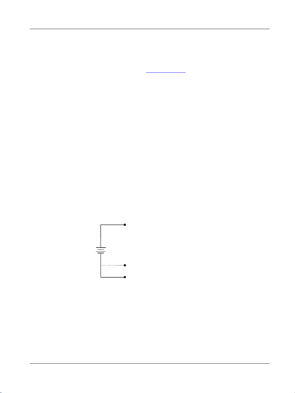
You can use the digital I/O terminals to detect the state of any TTL level input. In Figure
4-8, if the switch is set to the +5 V input, and the DIO0 reads TRUE (1). If the switch is
moved to GND, the DIO0 reads FALSE.
4-10
Page 51

miniLAB 1008 User's Guide Functional Details
DIO0
+5V+GND
Figure 4-8. Digital connection DIO0 detecting the state of a switch
Additional information on digital signal connections
For general information regarding digital signal connections and digital I/O techniques,
refer to the Guide to Signal Connections (available on our web site at
www.mccdaq.com/signals/signals.pdf).
Power terminals
The PC +5V connections on the screw terminal draw power from the USB connector.
The +5 V screw terminal is a 5 volt output that is supplied by the computer.
Caution! The +5 V terminals are outputs. Do not connect an external power supply to a
+5 V screw terminal, or you may damage the device and possibly the computer.
The maximum total output current that can be drawn from all miniLAB 1008
connections (power, analog and digital outputs) is 500 mA. This maximum applies to
most personal computers and self-powered USB hubs. Bus-powered hubs and notebook
computers may limit the available output current to 100 mA.
Just connecting the miniLAB 1008 to your computer draws 20 mA of current from the
USB +5V supply. Once you start running applications with the device, each DIO bit can
draw up to 2.5 mA, and each analog output can draw 30 mA. The maximum amount of
+5 V current available to the user is the difference between the total current requirement
of the PMD (based on the application), and the allowed current draw of the PC platform
(again, 500 mA for desktop PCs and self-powered hubs, or 100 mA for bus-powered
hubs and notebook computers).
With all outputs at their maximum output current, you can calculate the total current
requirement of the miniLAB 1008 device's USB +5 V as follows:
(miniLAB 1008 @ 20 mA) + (4 DIO @ 2.5 mA ea) + (2 AO @ 30 mA ea ) = 90 mA
For an application running on a PC or powered hub, this value yields a maximum user
current of 500 mA − 90 mA = 410 mA. This number is the total maximum available
current at the PC +5 V screw terminals. Measurement Computing highly recommends
that you figure in a safety factor of 20% below this maximum current loading for your
applications. A conservative, safe user maximum in this case would be in the
300-320 mA range.
4-11
Page 52

miniLAB 1008 User's Guide Functional Details
Since laptop computers typically allow up to 100 mA, the miniLAB 1008 in a fullyloaded configuration may be above that allowed by the computer. In this case, you must
determine the per-pin loading in the application to ensure that the maximum loading
criteria is met. The per-pin loading is calculated by simply dividing the +5V by the load
impedance of the pin in question.
Ground terminals
There are 9 identical ground connections that provide a common ground for all
miniLAB 1008 functions. Refer to the pinout diagrams on page 4-6 for the location of
the GND terminal pins.
Calibration terminal
The CAL connection on the output terminal provides a calibration reference voltage.
This terminal should only be used during calibration of the miniLAB 1008 device.
Calibration of the miniLAB 1008 is software-controlled via InstaCal. Refer to
"Calibrating with InstaCal
" on page 5-1 for calibration instructions.
Testing terminal
The TST terminal is reserved for factory testing only.
Counter terminal
The input connection to the 32-bit external event counter is made to the screw terminal
labeled CTR. Refer to the pinout diagrams on page 4-6 for the location of this pin. The
internal counter increments whenever the CTR input voltage changes from <1 volt to
more than 4 volts. The counter is capable of counting frequencies up to 1 MHz.
Accuracy
The overall accuracy of any instrument is limited by the error components within the
system. Quite often, resolution is incorrectly used to quantify the performance of a
measurement product. While "12-bits" or "1 part in 4096" does indicate what can be
resolved, it provides little insight into the quality of an absolute measurement. Accuracy
specifications describe the actual results that can be realized with a measurement device.
4-12
Page 53

miniLAB 1008 User's Guide Functional Details
e
There are three types of errors which affect the accuracy of a measurement system:
offset
gain
nonlinearity
The primary error sources in the miniLAB 1008 are offset and gain. Nonlinearity is
small in the miniLAB 1008, and is not significant as an error source with respect to
offset and gain.
Figure 4-9
shows an ideal, error-free, miniLAB 1008 transfer function. The typical
calibrated accuracy of the miniLAB 1008 is range-dependent, as explained in the
"Specifications
" chapter of this document. We use a ±10 V range here as an example of
what you can expect when performing a measurement in this range.
The accuracy plot in Figure 4-9 is drawn for clarity and is not drawn to scale.
Input Voltage
+FS
Output Cod
0
Figure 4-9. Ideal ADC transfer function
2048
-FS
4095
The miniLAB 1008's offset error is measured at mid-scale. Ideally, a zero-volt input
should produce an output code of 2048. Any deviation from this is an offset error. Fi
shows the miniLAB 1008 transfer function with an offset error. The typical offset
4-10
gure
error specification on the ±10 V range is ±9.77 millivolts (mV). Offset error affects all
codes equally by shifting the entire transfer function up or down along the input voltage
axis.
4-13
Page 54

miniLAB 1008 User's Guide Functional Details
e
V
The accuracy plots in Figure 4-10 are drawn for clarity and are not drawn to scale.
Input Voltage
+FS
Ideal
2
2048
9.77mV
Output Cod
4095
0
Actual
Offset=9.77mV
-FS
Figure 4-10. ADC transfer function with offset error
Gain error is a change in the slope of the transfer function from the ideal, and is typically
expressed as a percentage of full-scale. shows the miniLAB 1008 transfer
Figure 4-11
function with gain error. Gain error is easily converted to voltage by multiplying the
full-scale (FS) input by the error.
The accuracy plots in Figure 4-11 are drawn for clarity and are not drawn to scale.
Input Voltage
+FS
Ideal
Gain error=+0.2%, or +20 m
Gain error=-0.2%, or -20 mV
Actual
0
2048
-FS
Output Code
4095
Figure 4-11. ADC Transfer function with gain error
4-14
Page 55

miniLAB 1008 User's Guide Functional Details
For example, the miniLAB 1008 exhibits a typical calibrated gain error of ±0.2% on all
ranges. For the ±10 V range, this would yield 10V × ±0.002 = ±20 mV. This means that
at full scale, neglecting the effect of offset for the moment, the measurement would be
within 20 mV of the actual value. Note that gain error is expressed as a ratio. Values
near ±FS are more affected from an absolute voltage standpoint than are values near
mid-scale, which see little or no voltage error.
Combining these two error sources in , we have a plot of the error band of
Figure 4-12
the miniLAB 1008 for the ±10 V range. This is a graphical version of the typical
accuracy specification of the product.
The accuracy plots in Figure 4-12 are drawn for clarity and are not drawn to scale
Ideal +9.77mV + 20 mV
Ideal
Ideal -(9.77mV + 20 mV)
Input Voltage
9.77mV
0
Figure 4-12. Error band plot
+FS
2048
-FS
Ideal +9.77mV + 20 mVIdeal +9.77mV + 20 mV
Ideal
Ideal -(9.77mV + 20 mV)
Output Code
4095
Channel gain queue
The miniLAB 1008's channel gain queue feature allows you to set up a scan sequence
with a unique per-channel gain setting and channel sequence.
The channel gain queue feature removes the restriction of using an ascending channel
sequence at a fixed gain. This feature creates a channel list which is written to local
memory on the miniLAB 1008. This list is made up of a channel number and range
setting. An example of a four-element list is shown in . Table 4-4
4-15
Page 56

miniLAB 1008 User's Guide Functional Details
Table 4-4. Sample channel gain queue list
Element Channel Range
0 CH0 BIP10V
1 CH0 BIP5V
2 CH7 BIP10V
3 CH2 BIP1V
When a scan begins with the gain queue enabled, the miniLAB 1008 reads the first
element, sets the appropriate channel number and range, and then acquires a sample. The
properties of the next element are then retrieved, and another sample is acquired. This
sequence continues until all elements in the gain queue have been selected. When the
end of the channel list is detected, the sequence returns to the first element in the list.
This sequence repeats until the specified number of samples is gathered. You must
carefully match the gain to the expected voltage range on the associated channel—
otherwise, an over range condition can occur. Although this condition does not damage
the miniLAB 1008, it does produce a useless full-scale reading. It can also introduce a
long recovery time from saturation, which can affect the next measurement in the queue.
Digital connector cabling
Table 4-5 lists the digital I/O connector, applicable cables and accessory equipment. The
x in the compatible cable name indicates the length of the cable.
Table 4-5. Digital connector and accessory equipment
Connector type 37 D-Type, shielded
Compatible cables
Compatible accessory products CIO-MINI37
C37FF-x (Figure 4-13)
C37FFS- x (Figure 4-14)
C37FM- x (Figure 4-15)
SSR-RACK24
SSR-RACK08
CIO-ERB24
CIO-ERB08
4-16
Page 57

miniLAB 1008 User's Guide Functional Details
The red stripe
1
20
37
19
identifies pin # 1
1
19
20
37
Female connector Female connector
Figure 4-13. C37FF-x cable
1
20
19
37
1
19
20
37
Figure 4-14. C37FFS-x cable
The red stripe
1
20
37
19
identifies pin # 1
20
37
1
19
Female connector Male connector
Figure 4-15. C37FM- x cable
4-17
Page 58

Page 59
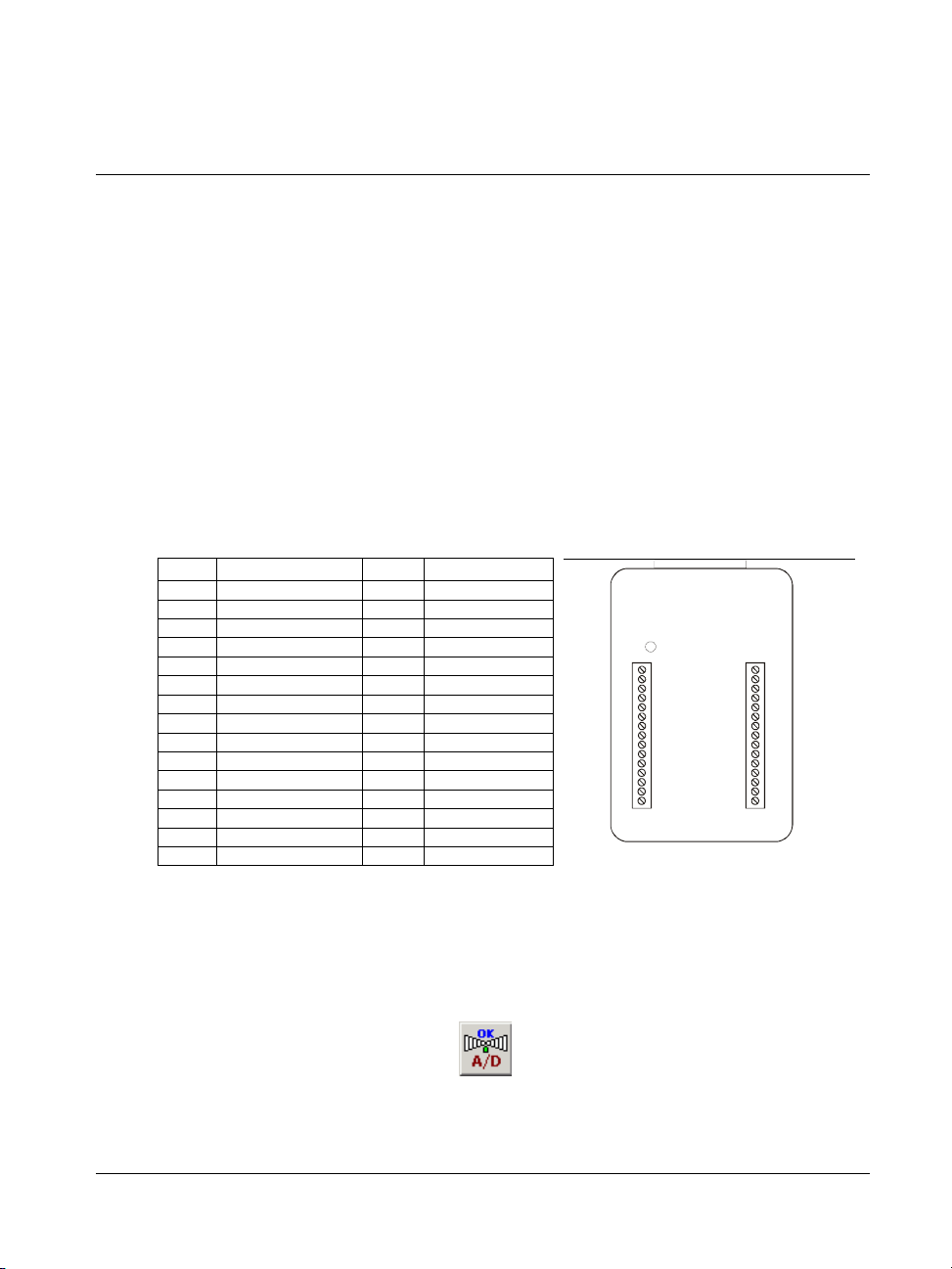
Calibrating and Testing the Device
Calibrating with InstaCal
InstaCal's calibration feature calibrates the offset and gain corrections for the miniLAB
1008's analog inputs. These corrections are stored in nvRAM. You should calibrate the
miniLAB 1008 every six months.
You can calibrate an individual channel, a range of channels, or all channels at the same
time. If you calibrate only selected analog input channels, any existing calibration
coefficients for channels not included in the calibration are preserved.
The pin numbers and associated signals on the miniLAB 1008 are specified below for
differential mode. Refer to these pin numbers when making connections to the inputs
Pin Signal Name Pin Signal Name
1 CH0 IN HI 16 DIO0
2 CH0 IN LO 17 DIO1
3 GND 18 GND
4 CH1 IN HI 19 DIO2
5 CH1 IN LO 20 DIO3
6 GND 21 GND
7 CH2 IN HI 22 D/A OUT 0
8 CH2 IN LO 23 D/A OUT 1
9 GND 24 GND
10 CH3 IN HI 25 CTR
11 CH3 IN LO 26 GND
12 GND 27 GND
13 PC+5V 28 PC+5V
14 PC+5V 29 PC+5V
15 CAL 30 TST
CH0 IN HI 1
CH0 IN LO 2
GND 3
CH1 IN HI 4
CH1 IN LO 5
GND 6
CH2 IN HI 7
CH2 IN LO 8
GND 9
CH3 IN HI 10
CH3 IN LO 11
GND 12
PC +5 V 13
PC +5 V 14
CAL 15
Chapter 5
16 DIO0
17 DIO1
18 GND
19 DIO2
20 DIO3
21 GND
22 D/A OUT0
23 D/A OUT1
24 GND
25 CTR
26 GND
27 GND
28 PC +5 V
29 PC +5 V
30 TST
To calibrate the miniLAB 1008, follow the steps below.
1.
Click on Start > Measurement Computing > InstaCal to launch the InstaCal
software. The InstaCal main form opens.
2.
Pull down the Calibrate menu and select A/D, or click on the Calibrate A/D icon.
5-1
Page 60
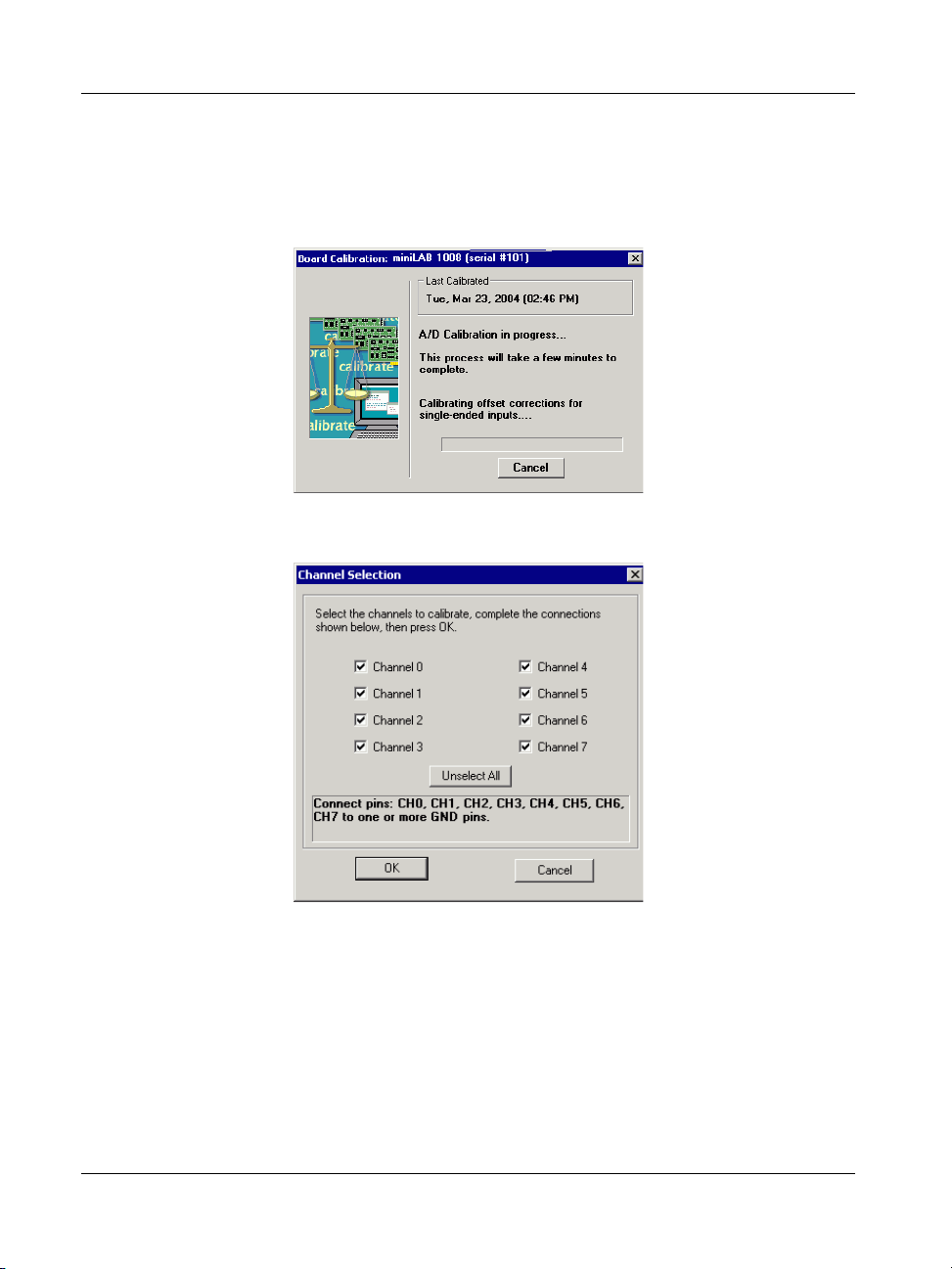
miniLAB 1008 User's Guide Calibrating and Testing the Device
The Board Calibration dialog opens, followed by the Channel Select dialog. This
dialog displays the date when the miniLAB 1008 was last calibrated. If the
miniLAB 1008 was calibrated within the previous six months, it may not need
calibrating.
The Channel Selection dialog automatically opens after the Board Calibration dialog.
By default, all of the analog input channels are selected for calibration. To calibrate
specific channels, click on the
Unselect All button to remove the check mark from
each channel (the button label also changes to Select All), and then click in the
check box of the channel(s) you want to calibrate. The dialog dynamically updates
with the pin numbers of the channel(s) to connect to a ground terminal (GND).
This procedure shows you how to calibrate all of the analog input channels.
3. Connect each analog input (pin CH0, CH1, CH2, CH3, CH4, CH5, CH6 and CH7)
to one or more ground (GND) terminals, as directed in the
Channel Selection
dialog.
5-2
Page 61
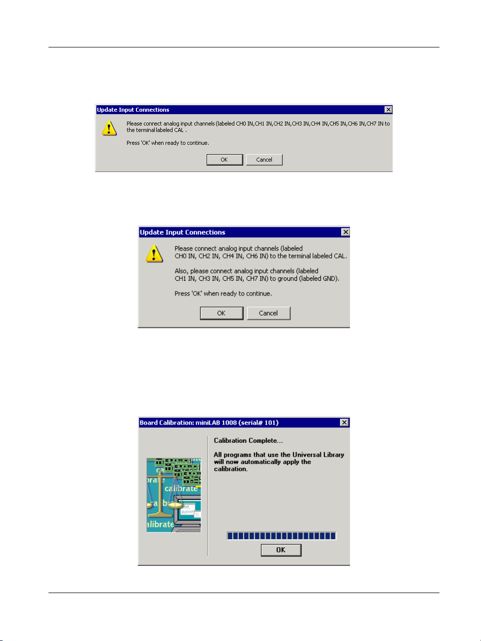
miniLAB 1008 User's Guide Calibrating and Testing the Device
4. Click the OK button to begin calibration. The first of two Update Input
Connections dialog opens.
5. Connect the analog input pins labeled CH0 IN, CH1 IN, CH2 IN, CH3 IN, CH4 IN,
CH5 IN, CH6 IN, and CH7 IN to the CAL output (pin 15) and press OK. The
second Update Input Connections dialog opens.
6. Connect the analog input channels labeled CH0 IN, CH2 IN, CH4 IN, and CH6 IN
to the CAL output (pin 15), and connect the analog input channels labeled CH1 IN,
CH3 IN, CH5 IN, and CH7 IN to one or more GND terminals, and then click the
OK button.
When all of the gain and offset corrections are calibrated, the following dialog
opens.
7. Click the OK button to exit the calibration procedure.
5-3
Page 62
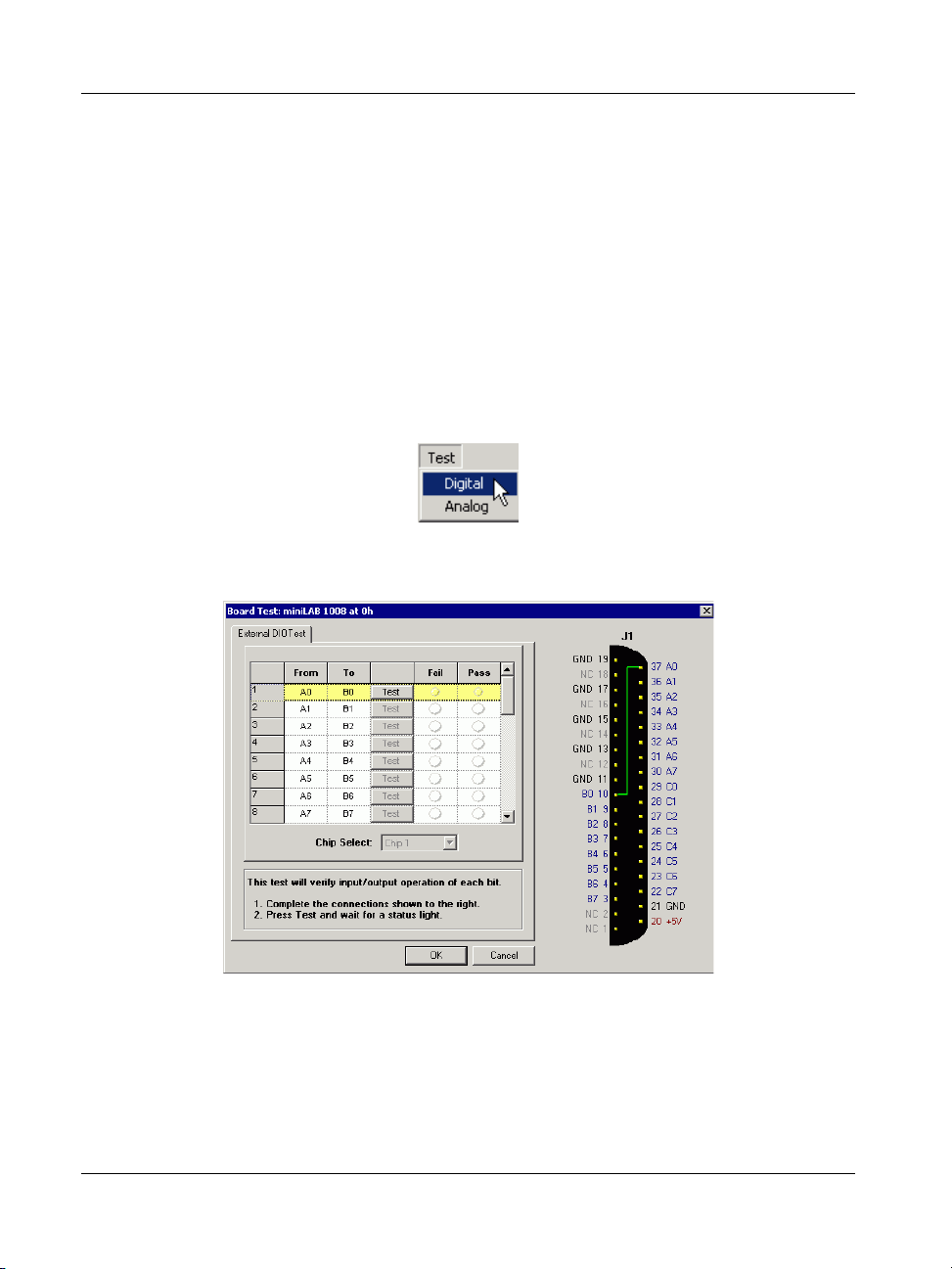
miniLAB 1008 User's Guide Calibrating and Testing the Device
Testing with InstaCal
InstaCal provides test procedures that you can perform to verify that the miniLAB 1008
analog and digital functions are working properly. To access these tests, start InstaCal,
and select the desired test option from the
Testing the digital functions
The external DIO test verifies that the input/output operation of each digital bit is
functional. To access this test, do the following:
1. From InstaCal’s main form, pull down the Test menu and select the Digital option.
The Board Test dialog opens with one tab – the External DIO Test tab. The
following dialog is shown configured with its default settings.
Test menu.
Row 1 is highlighted – this is where you begin the test. Follow the wiring
instructions on the dialog.
2. Connect the signals as specified in row 1. Pin numbers are listed in the wire
illustration.
For example, wire signal
button.
A0 (pin 37) to signal B0 (pin 10) and click on the Test
5-4
Page 63
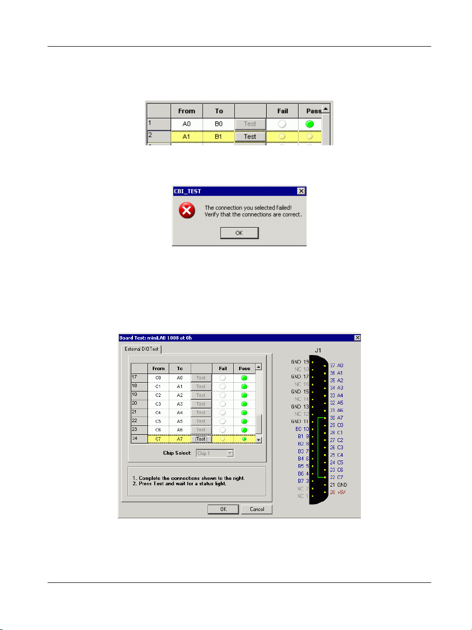
miniLAB 1008 User's Guide Calibrating and Testing the Device
o The Pass status light illuminates green to indicate a successful test, and the
next row is automatically highlighted for the next signal test.
o If the Fail status LED turns red, the test on the connection failed, and the
following dialog displays.
Click on the OK button, check your connections, and repeat the test. If you verify
the connection and the test still fails, contact MCC Technical Support.
3. Repeat the test in each row until all of the signals have been tested. The wire
illustration dynamically updates the numbers of the pins that you connect in each
row. The dialog below shows the
External DIO Test dialog after you pass all of the
digital signal tests.
4. When you are done testing the digital channels, click on the OK button to return to
InstaCal’s main form.
5-5
Page 64

miniLAB 1008 User's Guide Calibrating and Testing the Device
Testing the analog functions
InstaCal provides two tests that verify that the miniLAB 1008's analog functions are
working properly—a loop back test and a scan test.
The loop back test is a non-paced analog input test that verifies that a single analog
input is functional.
The scan test is a paced analog input test verifies that multiple analog inputs and the
pacer circuit are functional.
To access these tests, do the following:
1. From InstaCal’s main form, pull down the
Test menu and select Analog.
The Board Test dialog opens with two tabs – the Analog Loop Back Test tab and
the Scan Test tab. The dialog is shown configured with its default settings.
2. Click on the tab of the test you want to perform and follow the procedures listed
below.
5-6
Page 65

miniLAB 1008 User's Guide Calibrating and Testing the Device
Running a loop back test
Run the loop back test to verify that a single analog input is functional. This test also
verifies that the onboard signal source—such as a digital output—is functional. In this
test, you wire a connection between a digital output, analog output, or external signal
source, and an analog input. To perform the loop back test, do the following:
1.
Select the input channel (CH 0 to CH 3, or CH 0 to CH 7 in single-ended mode),
signal source (DIO0 to DIO3, DAC0, DAC1, or External,) and range to test.
2.
Connect a wire between the pins. Use the wire illustration at the bottom of the
dialog as a reference for the pin numbers to connect.
3.
Verify that the specified waveform appears in the plot area.
In the example below, pin 1 (signal CH0 IN) is connected to pin 16 (signal DIO0).
This connection generates a square wave in the plot area.
When you change the input channel or signal source, the wire illustration dynamically
updates the pin numbers to connect, and the plot area displays the data from the selected
input channel.
Running a scan test
Run the scan test to verify that a range of analog inputs is functional. This is a more
advanced test than the loop back test, in that it also exercises the pacer circuit. In this
test, you apply a low frequency signal to one or more analog input channels. The UL
function
cbAInScan()reads the A/D voltage of each channel in the scan, and outputs
the data as a waveform in the plot area. The data is also output to a table.
5-7
Page 66

miniLAB 1008 User's Guide Calibrating and Testing the Device
To perform the scan test, do the following:
1. Click on the
Scan Test tab. The following dialog is shown configured with its
default settings.
2. Click on the Scan Options button. The Scan Options dialog opens. This dialog is
shown configured with its default settings.
3.
Select the channel(s) to scan, range, rate that you want to perform the scan test on
and click OK.
4.
Connect an external signal to each channel to be scanned, press the
Start button,
and verify the waveform(s) displayed in the plot area.
In the following example, a square wave is input to channel 0, and a sine wave is
input to channel 1.
5-8
Page 67

miniLAB 1008 User's Guide Calibrating and Testing the Device
Click the View Data button to launch the ScanView utility program and display the
data in a table. ScanView is included with the Universal Library software. The
following dialog shows the data generated from channel 0 and channel 1.
You can scroll to the bottom of the spreadsheet for a summary of the data.
5-9
Page 68

miniLAB 1008 User's Guide Calibrating and Testing the Device
You can print and save the data generated by the scan test from the options on the
File menu. The data, however, is in a proprietary format that cannot be exported or
modified.
You can click on the InstaCal – Scan Plots tab to display a graph of each channel.
5.
Click the X in the upper right corner of the dialog to return to the Scan Test dialog.
6.
When you are finished testing the miniLAB 1008 analog channels, click
OK to exit
the dialog and return to InstaCal’s main form.
5-10
Page 69

Specifications
Typical for 25 °C unless otherwise specified.
Analog Input Section
Parameter Conditions Specification
A/D converter type Successive approximation type
Input voltage range for linear
operation, single ended mode
Input voltage range for linear
operation, differential mode
Absolute maximum input
voltage
Input current (Note 1)
Number of channels
Input ranges, single ended
mode
Input ranges, differential mode ±20 V, G=1
Throughput
Channel Gain Queue Up to 8 elements
CAL accuracy CAL = 2.5 V ±0.05% typ, ±0.25% max
Chapter 6
CHx to GND ±10 V max
CHx to GND -10 V min, +20 V max
CHx to GND ±40 V max
Vin = +10 V 70 µA typ
Vin = 0 V -12 µA typ
Vin = -10 V -94 µA typ
8 single ended / 4 differential,
software selectable
±10 V, G=2
±10 V, G=2
±5 V, G=4
±4 V, G=5
±2.5 V, G=8
±2.0 V, G=10
±1.25 V, G=16
±1.0 V, G=20
Software selectable
Software paced 50 S/s
Continuous scan 1.2 kS/s
Burst scan to 4 k
sample FIFO
Differential 12 bits, no missing codes Resolution (Note 2)
Single ended 11 bits
8 kS/s
Software configurable channel,
range, and gain.
6-1
Page 70

miniLAB 1008 User's Guide Specifications
Parameter Conditions Specification
Integral linearity error ±1 LSB typ
Differential linearity error ±0.5 LSB typ
Repeatability ±1 LSB typ
Source 5 mA max CAL current
Sink 20 µA min, 200 nA typ
Trigger Source Software selectable External Digital: DIO0-DIO3
Note 1:
Input current is a function of applied voltage on the analog input channels. For
a given input voltage, Vin, the input leakage is approximately equal to
(8.181*Vin-12) µA.
Note 2:
The AD7870 converter only returns 11-bits (0-2047 codes) in single-ended
mode.
Table 6-1. Accuracy, differential mode
Range Accuracy (LSB)
±20 V 5.1
±10 V 6.1
±5 V 8.1
±4 V 9.1
±2.5 V 12.1
±2 V 14.1
±1.25 V 20.1
±1 V 24.1
Table 6-2. Accuracy, single-ended mode
Range Accuracy (LSB)
±10 V 4.0
Table 6-3. Accuracy components, differential mode - All values are (±)
Range % of
Reading
±20 V 0.2 40 9.766 49.766
±10 V 0.2 20 9.766 29.766
±5 V 0.2 10 9.766 19.766
±4 V 0.2 8 9.766 17.766
±2.5 V 0.2 5 9.766 14.766
±2 V 0.2 4 9.766 13.766
±1.25 V 0.2 2.5 9.766 12.266
±1 V 0.2 2 9.766 11.766
Gain Error
at FS (mV)
Offset (mV) Accuracy at FS (mV)
6-2
Page 71

miniLAB 1008 User's Guide Specifications
Table 6-4. Accuracy components, single-ended mode
Range % of
Reading
±10 V 0.2 20 19.531 39.531
Gain Error
at FS (mV)
Analog Output Section
Parameter Conditions Specification
D/A converter type PWM
Resolution 10-bits, 1 in 1024
Maximum output range 0 -5 Volts
Number of channels 2 voltage output
Throughput Software paced 100 S/s single channel mode
Power on and reset voltage Initializes to 000h code
Maximum voltage (Note 3)
Output drive Each D/A OUT 30 mA
Slew rate 0.14 V/mS typ
Note 3: Vs is the USB bus +5V power. The maximum analog output voltage is equal to
Vs at no-load. V is system dependent and may be less than 5 volts.
Offset (mV) Accuracy at FS (mV)
50 S/s dual channel mode
No Load Vs
1mA Load 0.99*Vs
5mA Load 0.98*Vs
Digital Input / Output (Screw Terminal DIO3:0)
Parameter Conditions Specification
Digital type Discrete, 5 V/TTL compatible
Number of I/O 4
Configuration
Input high voltage 3.0 V min, 15.0 V absolute max
Input low voltage 0.8 V max
No Load Vs - 0.4 V min, Vs typ Output voltage (Note 4)
1 mA Load Vs - 1.5 V
Input leakage current ±1.0 µA
Output short-circuit current (Note 4) Output High 3.3 mA
Power-up / reset state Input mode (high impedance)
Note 4: The DIO[3:0] lines available at the screw terminals are protected with
1.5 kOhm series resistors.
6-3
4 bits, independently
programmable for input or output.
Page 72

miniLAB 1008 User's Guide Specifications
Digital Input / Output (DB37)
Digital type 82C55
Number of I/O 24 (Port A0 through Port C7)
Configuration 2 banks of 8 and 2 banks of 4, or 3 banks of 8
Pull up/pull-down configuration
Input high voltage 2.0 V min, 5.5 V absolute max
Input low voltage 0.8 V max, –0.5 V absolute min
Output high voltage (IOH = -2.5 mA) 3.0 V min
Output low voltage (IOL = 2.5 mA) 0.4 V max
All pins pulled up to Vs via 47 k resistors (default).
Positions available for pull down to ground.
Hardware selectable via zero ohm resistor.
External Trigger
Parameter Conditions Specification
Trigger source External digital
Trigger mode
Trigger latency Burst 25 µs min, 50 µs max
Trigger pulse width Burst 40 µs min
Input high voltage 3.0 V min, 15.0 V absolute max
Input low voltage 0.8 V max
Input leakage
current
Software
selectable
±1.0 µA
DIO[3:0], only DIO may be selected as a trigger
input
Level sensitive: user configurable for TTL level high
or low input.
Counter Section
Counter type Event counter
Number of channels 1
Input source CTR screw terminal
Resolution 32 bits
Schmidt trigger hysteresis 20 mV to 100 mV
Input leakage current ±1 µA
Maximum input frequency 1 MHz
High pulse width 500 ns min
Low pulse width 500 ns min
Input low voltage 0 V min, 1.0 V max
Input high voltage 4.0 V min, 15.0 V max
6-4
Page 73

miniLAB 1008 User's Guide Specifications
Non-volatile Memory
Memory size
Memory configuration
8192 bytes
Address Range Access Description
0x0000 – 0x17FF Read/Write A/D data (4 k samples)
0x1800 – 0x1EFF Read/Write User data area
0x1F00 – 0x1FEF Read/Write Calibration data
0x1FF0 – 0x1FFF Read/Write System data
Power
Parameter Conditions Specification
Supply current (Note 5) 20 mA
+5 V USB power available
(Note 6)
Note 5:
This is the total current requirement for the miniLAB-1008 which includes up
to 5 mA for the status LED.
Connected to Self-Powered Hub 4.5 V min, 5.25 V max
Connected to Bus-Powered Hub 4.1 V min, 5.25 V max
Connected to Self-Powered Hub 450 mA min, 500 mA max Output current (Note 7)
Connected to Bus-Powered Hub 50 mA min, 100 mA max
Note 6:
Self-powered refers to USB hubs and hosts with a power supply. Bus-powered
refers to USB hubs and hosts without their own power supply.
Note 7:
This refers to the total amount of current that can be sourced from the USB
+5 V, analog outputs and digital outputs.
General
Parameter Conditions Specification
USB Controller clock error
Device type USB 1.1 low-speed
Device compatibility USB 1.1, USB 2.0
Environmental
Operating temperature range -40 to 85 °C
Storage temperature range -40 to 85 °C
Humidity 0 to 90% non-condensing
25 °C ±30 ppm max
0 to 70 °C ±50 ppm max
-40 to 85 °C ±100 ppm max
6-5
Page 74

miniLAB 1008 User's Guide Specifications
Mechanical
Case dimensions 157 mm (L) x 102 mm (W) x 40 mm (H), including connectors
USB cable length 3 meters max
User connection length 3 meters max
Main connector and pin out
Connector type Screw terminal
Wire gauge range 12 AWG to 22 AWG
6-6
Page 75
miniLAB 1008 User's Guide Specifications
4-channel differential mode
Pin Signal Name Pin Signal Name
1 CH0 IN HI 16 DIO0
2 CH0 IN LO 17 DIO1
3 GND 18 GND
4 CH1 IN HI 19 DIO2
5 CH1 IN LO 20 DIO3
6 GND 21 GND
7 CH2 IN HI 22 D/A OUT 0
8 CH2 IN LO 23 D/A OUT 1
9 GND 24 GND
10 CH3 IN HI 25 CTR
11 CH3 IN LO 26 GND
12 GND 27 GND
13 PC +5 V 28 PC +5 V
14 PC +5 V 29 PC +5 V
15 CAL 30 TST
8-channel single-ended mode
Pin Signal Name Pin Signal Name
1 CH0 IN 16 DIO0
2 CH1 IN 17 DIO1
3 GND 18 GND
4 CH2 IN 19 DIO2
5 CH3 IN 20 DIO3
6 GND 21 GND
7 CH4 IN 22 D/A OUT 0
8 CH5 IN 23 D/A OUT 1
9 GND 24 GND
10 CH6 IN 25 CTR
11 CH7 IN 26 GND
12 GND 27 GND
13 PC +5 V 28 PC +5 V
14 PC +5 V 29 PC +5 V
15 CAL 30 TST
DB37 connector and pin out
Connector type 37 D-type, shielded
Compatible cables
Compatible accessory products CIO-MINI37
C37FF-x
C37FFS-x
C37FM-x
SSR-RACK24
SSR-RACK08
CIO-ERB24
CIO-ERB08
6-7
Page 76

miniLAB 1008 User's Guide Specifications
Pin Signal Name Pin Signal Name
1 n/c 20 USB +5V
2 n/c 21 GND
3 Port B7 22 Port C7
4 Port B6 23 Port C6
5 Port B5 24 Port C5
6 Port B4 25 Port C4
7 Port B3 26 Port C3
8 Port B2 27 Port C2
9 Port B1 28 Port C1
10 Port B0 29 Port C0
11 GND 30 Port A7
12 n/c 31 Port A6
13 GND 32 Port A5
14 n/c 33 Port A4
15 GND 34 Port A3
16 n/c 35 Port A2
17 GND 36 Port A1
18 n/c 37 Port A0
19 GND
6-8
Page 77

Declaration of Conformity
Manufacturer: Measurement Computing Corporation
Address: 16 Commerce Boulevard
Middleboro, MA 02346
USA
Category: Electrical equipment for measurement, control and laboratory use.
Measurement Computing Corporation declares under sole responsibility that the product
miniLAB 1008
to which this declaration relates is in conformity with the relevant provisions of the
following standards or other documents:
EU EMC Directive 89/336/EEC: Electromagnetic Compatibility, EN 61326 (1997)
Amendment 1 (1998)
Emissions: Group 1, Class A
EN 55011 (1998)/CISPR 11: Radiated and Conducted emissions.
Immunity: EN61326, Annex A
EN 61000-4-2 (1995): Electrostatic Discharge immunity, Criteria C.
EN 61000-4-3 (1997): Radiated Electromagnetic Field immunity Criteria A.
EN 61000-4-8 (1995): Power Frequency Magnetic Field immunity Criteria A.
Power line and I/O tests to EN61000-4-4, EN61000-4-5, EN61000-4-6, and
EN61000-4-11 were not required. The device is DC powered from an I/O cable which is
less than three meters long.
Declaration of Conformity based on tests conducted by Chomerics Test Services,
Woburn, MA 01801, USA in June, 2004. Test records are outlined in Chomerics Test
Report #EMI3902.04.
We hereby declare that the equipment specified conforms to the above Directives and
Standards.
Carl Haapaoja, Vice-President of Design Verification
Page 78

Measurement Computing Corporation
16 Commerce Boulevard,
Middleboro, Massachusetts 02346
(508) 946-5100
Fax: (508) 946-9500
E-mail: info@mccdaq.com
www.mccdaq.com
 Loading...