

Page 1

E-DIO24-OEM
User's Guide
Ethernet-based Digital I/O
Document Revision 1A
October 2015
© Copyright 2015
Page 2

HM E-DIO24-OEM.docx
Trademark and Copyright Information
Measurement Computing Corporation, InstaCal, Universal Library, and the Measurement Computing logo are
either trademarks or registered trademarks of Measurement Computing Corporation. Refer to the Copyrights &
Trademarks section on mccdaq.com/legal for more information about Measurement Computing trademarks.
Other product and company names mentioned herein are trademarks or trade names of their respective
companies.
© 2015 Measurement Computing Corporation. All rights reserved. No part of this publication may be
reproduced, stored in a retrieval system, or transmitted, in any form by any means, electronic, mechanical, by
photocopying, recording, or otherwise without the prior written permission of Mea
Corporation.
Notice
Measurement Computing Corporation does not authorize any Measurement Computing Corporation product for
use in life support systems and/or devices without prior written consent from Measurement Computing
Corporation. Life support devices/systems are devices or systems that, a) are intended for surgical implantation
into the body, or b) support or sustain life and whose failure to perform can be reasonably expected to result in
injury. Measurement Computing Corporation products are not designed with the components required, and are
not subject to the testing required to ensure a level of reliability suitable for the treatment and diagnosis of
people.
surement Computing
Page 3

Table of Contents
Preface
About this User's Guide ....................................................................................................................... 5
What you will learn from this user's guide ......................................................................................................... 5
Conventions in this user's guide ......................................................................................................................... 5
Where to find more information ......................................................................................................................... 5
Chapter 1
Introducing the E-DIO24-OEM ............................................................................................................. 6
Ethernet interface ................................................................................................................................................ 6
Functional block diagram ................................................................................................................................... 6
Chapter 2
Installing the E-DIO24-OEM .................................................................................................................. 7
Unpacking........................................................................................................................................................... 7
Downloading the software .................................................................................................................................. 7
Connecting external power ................................................................................................................................. 7
Connecting the E-DIO24-OEM .......................................................................................................................... 7
Configuring network settings ............................................................................................................................. 8
Address mode ................................................................................................................................................................... 8
IP address settings ............................................................................................................................................................. 8
Configuring the network router for communication across networks ................................................................ 9
Network alarm .................................................................................................................................................... 9
Restoring factory default network settings ......................................................................................................... 9
Updating firmware ................................................................................................................................ .............. 9
Firmware update mode ..................................................................................................................................................... 9
Chapter 3
Functional Details ............................................................................................................................... 10
Components ...................................................................................................................................................... 10
Header connectors ............................................................................................................................................................10
LED status indicators .......................................................................................................................................................11
Ethernet connector ...........................................................................................................................................................11
External power connectors ...............................................................................................................................................12
Factory reset button .........................................................................................................................................................12
Signal connections ............................................................................................................................................ 12
Digital I/O ........................................................................................................................................................................12
Counter input ...................................................................................................................................................................13
Voltage output .................................................................................................................................................................13
Ground ................................................................................................................................................................ .............14
Mechanical drawings ................................................................................................................................ ........ 14
Chapter 4
Specifications ...................................................................................................................................... 15
Digital input/output........................................................................................................................................... 15
Counter ............................................................................................................................................................. 16
Memory ............................................................................................................................................................ 16
Power ................................................................................................................................................................ 16
Network ............................................................................................................................................................ 17
Ethernet connection .........................................................................................................................................................17
Network interface ............................................................................................................................................................17
Network factory default settings ......................................................................................................................................17
Network security ..............................................................................................................................................................17
LED displays and the factory reset button ........................................................................................................ 18
3
Page 4

E-DIO24-OEM User's Guide
Environmental .................................................................................................................................................. 18
Mechanical ....................................................................................................................................................... 18
Header connector .............................................................................................................................................. 18
Screw terminal connector (not populated) ........................................................................................................ 19
4
Page 5

Preface
About this User's Guide
What you will learn from this user's guide
This user's guide describes the Measurement Computing E-DIO24-OEM data acquisition device and lists device
specifications.
Conventions in this user's guide
For more information
Text presented in a box signifies additional information and helpful hints related to the subject matter you are
reading.
Caution! Shaded caution statements present information to help you avoid injuring yourself and others,
damaging your hardware, or losing your data.
bold text Bold text is used for the names of objects on a screen, such as buttons, text boxes, and check boxes.
italic text Italic text is used for the names of manuals and help topic titles, and to emphasize a word or phrase.
Where to find more information
Additional information about E-DIO24-OEM hardware is available on our website at www.mccdaq.com. You
can also contact Measurement Computing Corporation by phone, fax, or email with specific questions.
Knowledgebase: kb.mccdaq.com
Tech support form: www.mccdaq.com/support/support_form.aspx
Email: techsupport@mccdaq.com
Phone: 508-946-5100 and follow the instructions for reaching Tech Support
5
Page 6

Chapter 1
Introducing the E-DIO24-OEM
The E-DIO24-OEM is an Ethernet based digital I/O data acquisition device that is compatible with TCP (IPv4
only) and UDP network protocols. The E-DIO24-OEM provides the following features:
24 individually-configurable digital I/O bits
±24 mA drive capability
Software-paced transfer rates up to 5 kHz (typical throughput on a local network)
One 32-bit event counter (shared with a DIO pin)
Remote network access, configuration, and alarm
Header connectors for field wiring connections
Functionally equivalent to USB-DIO24 Series and USB-1024 Series hardware.
The E-DIO24-OEM requires a 5 VDC external power supply (available separately).
Ethernet interface
The E-DIO24-OEM has one built-in 10/100 BASE-T auto-negotiation, high-speed communication port. You
can remotely access and configure your E-DIO24-OEM from anywhere on the network. Only one computer can
control the E-DIO24-OEM at one time. The networking protocols are TCP and UDP.
A unique media access control (MAC) address is assigned to each device at the factory. You configure the
Ethernet connection settings through software. A network name in the format E-DIO24-xxxxxx, is assigned to
the device, where xxxxxx represents the lower six characters of the device MAC address.
Functional block diagram
E-DIO24-OEM functions are illustrated in the block diagram shown here.
Figure 1. Functional block diagram
6
Page 7

Chapter 2
Installing the E-DIO24-OEM
Unpacking
As with any electronic device, you should take care while handling to avoid damage from static
electricity. Before removing the device from its packaging, ground yourself using a wrist strap or by simply
touching the computer chassis or other grounded object to eliminate any stored static charge.
Contact us immediately if any components are missing or damaged.
Downloading the software
Refer to the E-DIO24-OEM product page on the on the Measurement Computing website for information about
the supported software you can download.
Install the software before you install the hardware
The driver needed to run the device is installed when you install the software. Therefore, you need to install the
software package you plan to use before you install the hardware.
Connecting external power
E-DIO24-OEM operation requires a 5 volt power supply. External power can be connected to either the barrel
connector (J4) or 2-pin terminal block (W1).
Connect a 5 VDC supply to either connector J4 or W1
Do not attempt to apply power to both external power connectors simultaneously.
A 5 volt, 1 amp external power adapter (PS-5V1AEPS) is available as a separate purchase for connection to J4.
The Power LED turns on when 5 V power is supplied. If the voltage supply is less than 4.2 V or more than
5.6 V, the POWER LED does not turn on. Refer to Figure 2 on page 10 for the location of the Power LED.
Connecting the E-DIO24-OEM
The E-DIO24-OEM requires a TCP and UDP connection to a network or computer.
Using the Ethernet cable provided, connect the E-DIO24-OEM to a 10Base-T- or 100Base-TX compatible
Ethernet port, hub, or switch. When connecting the E-DIO24-OEM for the first time, make sure that you
connect to a local network with DHCP enabled. If you are unsure whether you have access to a local network or
that DHCP is enabled on that network, you should connect directly to a Windows PC.
It may take a minute or two for the network DHCP server to detect the device and assign an address. The green
Link/activity LED on the lower left of the Ethernet connector turns on when a valid Ethernet link is established,
and blinks when network activity is detected.
Once the E-DIO24-OEM is physically connected to the local network or PC, you can run the software (InstaCal
for example) to establish a connection. If a connection cannot be established, make sure the device is using the
default configuration by following the instructions in the Restoring factory default network settings on page 9.
Once a connection is established and you can communicate with the device, you can change the configuration
for other network scenarios.
7
Page 8

E-DIO24-OEM User's Guide Installing the E-DIO24-OEM
Configuring network settings
The following E-DIO24-OEM network settings are software-selectable. One user at a time can connect to the
device and configure network options. The default settings are recommended for typical local networks.
Address mode
The address mode settings determine whether default IP parameters (IPv4 address, subnet mask, and gateway)
are assigned to the E-DIO24-OEM, or whether an auto-addressing method is used to assign these parameters.
DHCP or Link-Local enabled (default)
If connected to a network with a DHCP server, the service automatically assigns IP addresses to the E-DIO24OEM. If the connected network does not have a DHCP server, the address stored in the default IP address is
assigned.
If the E-DIO24-OEM is directly connected to a Windows PC or other host that supports link-local addressing, a
link-local address is assigned. A link-local address is valid only for communications between the E-DIO24OEM and the PC to which it is connected.
DHCP Only
This setting enables configuration by a DHCP server, if one is available. The E-DIO24-OEM is assigned an IP
address shortly after it is powered up and attached to the network.
Link-local Only
The E-DIO24-OEM is assigned a link-local IP address by the Windows PC or other host that supports link-local
addressing to which it is connected. A link-local address is valid only for communications between the
E-DIO24-OEM and the PC to which it is connected.
Static
The default IPv4 Address is manually configured on the E-DIO24-OEM.
IP address settings
The default settings of the following IP address are assigned to the E-DIO24-OEM when automatic addressing
is either disabled or not available (DHCP or link-local, for example):
IPv4 address – The IP address stored on the device. The default IPv4 address is 192.168.0.101.
Subnet mask – The subnet mask stored on the device. The subnet mask determines the number of bits of
the IP address that is used for the host portion of the address vs. the number of bits used for the network
portion. The default subnet mask is 255.255.255.000.
Gateway – The gateway IP address stored on the device. The gateway address of the device bridges
subnets within a network. The default gateway is 192.168.0.1.
Connection code
The connection code is number between 0 (default) and 999999999. Change this number from its default to
prevent other users from connecting to and configuring the device. When the code is set to a value other than 0,
the device remains visible to other users on the network, but connection by another user is not allowed.
8
Page 9

E-DIO24-OEM User's Guide Installing the E-DIO24-OEM
Configuring the network router for communication across networks
To communicate with the E-DIO24-OEM from a computer connected to a different network – such as over the
Internet – you must change the network configuration of the network router.
Caution! This procedure should only be performed by a network administrator or computer professional.
Incorrect settings can significantly disrupt a network.
Complete the following steps to configure the network router for communication across networks. In this
procedure, the E-DIO24-OEM is installed on the host LAN, and the computer is installed on the client LAN.
1. Connect the E-DIO24-OEM to a local network and determine its IP address.
If the address was assigned by DHCP, we recommend that you change it to a static address: set the default
address to the address assigned, and set the device network configuration to a static value.
2. Configure the firewall/router to forward incoming traffic to the following ports to the IP address assigned
to the device:
o UDP:54211 (discovery)
o TCP:54211 (commands)
3. On the computer connected to the client LAN, enter the WAN address of the host router, and specify the
ports that were forwarded to connect to the remote E-DIO24-OEM.
You can select a different port if the port above is not available on your router; however make sure that the
same port is configured for both UDP and TCP.
Network alarm
You can configure a digital output bit to change state when a host is connected to or disconnected from the
E-DIO24-OEM. All alarm settings are selectable with software.
Restoring factory default network settings
The reset button is used to restore the factory default network settings. The location of this button is shown in
Figure 2 on page 10.
To reset network configuration settings to factory default values, press and hold the Factory reset button for at
least four seconds until both the Power and Activity LEDs blink. When you release the button, the device starts
up with the network settings restored to factory default values. If you release the button before the two LEDs
blink, the settings are not affected and the device starts up normally. If InstaCal is open when default settings
are restored, click the Refresh Boards toolbar button to reflect the changes.
Updating firmware
The E-DIO24-OEM firmware can be updated in the field if required. Firmware available for download is posted
at www.mccdaq.com/firmware.aspx. MCC recommends that you check this page periodically to see if an
update to your device firmware is available.
Firmware update mode
If a firmware update fails, you can force the device into firmware update mode and use InstaCal to recover from
the failure.
To put the device into firmware update mode, press and hold the device reset button and apply power. The
device LEDs will continuously blink. InstaCal will detect a device in this mode as a bootloader device. Run
InstaCal and download the firmware. After downloading the firmware, refresh the device list and add the device
to InstaCal again.
9
Page 10

1
Header connector W6
6
Factory reset button
2
Pull-up/down jumper W3 (port 1)
7
Power (top) and Activity (bottom) LEDs
3
Pull-up/down jumper W4 (port 2)
8
Ethernet connector
4
Pull-up/down jumper W5 (port 0)
9
External power barrel connector J4
5
Header connector W2
10
External power header connector W1
Functional Details
Components
The E-DIO24-OEM has the following components, as shown in Figure 2:
Header connectors
LED status indicators
Ethernet connector
External power connectors
Factory reset button
Chapter 3
Figure 2. E-DIO24-OEM components
Header connectors
The E-DIO24-OEM header connectors are labeled W2 and W6 and provide the following connections:
24 digital I/O connections (P0D0 to P2D7)
One counter input (access with P2D7)
One voltage power output (+VO)
Ground (GND) connections
10
Page 11

E-DIO24-OEM User's Guide Functional Details
Pin
Signal name
Pin description
Pin
Signal name
Pin description
1
P0D0
Port 0 bit 0
2
P0D1
Port 0 bit 1
3
P0D2
Port 0 bit 2
4
P0D3
Port 0 bit 3
5
GND
Ground
6
P0D4
Port 0 bit 4
7
P0D5
Port 0 bit 5
8
P0D6
Port 0 bit 6
9
P0D7
Port 0 bit 7
10
GND
Ground
11
GND
Ground
12
P2D0
Port 2 bit 0
13
P2D1
Port 2 bit 1
14
P2D2
Port 2 bit 2
15
P2D3
Port 2 bit 3
16
GND
Ground
Pin
Signal name
Pin description
Pin
Signal name
Pin description
1
P1D0
Port 1 bit 0
2
P1D1
Port 1 bit 1
3
P1D2
Port 1 bit 2
4
P1D3
Port 1 bit 3
5
GND
Ground
6
P1D4
Port 1 bit 4
7
P1D5
Port 1 bit 5
8
P1D6
Port 1 bit 6
9
P1D7
Port 1 bit 7
10
+VO
User voltage output
11
GND
Ground
12
P2D4
Port 2 bit 4
13
P2D5
Port 2 bit 5
14
P2D6
Port 2 bit 6
15
P2D7
Port 2 bit 7 / Counter
16
GND
Ground
W6 pinout
W2 pinout
The signal location of each pinout is shown in Figure 3.
Figure 3. Header connector pinout, typical
LED status indicators
The E-DIO24-OEM has two LED indicators that indicate the status of power and host communications. The
LEDs are stacked one above the other:
The Power LED (top) is on when external power between 4.2 V to 5.6 V is supplied.
This LED is off when the external power supply is not connected, or the input power is outside of the 4.2 V
to 5.6 V voltage range of the external supply, causing a power fault.
The E-DIO24-OEM has an onboard voltage supervisory circuit that monitors the 5 V external power
supply.
The Activity LED (bottom) is on when a valid host connection is detected.
This LED blinks when a command is received.
Both Power and Activity LEDs blink once when factory default settings are restored. Refer to Restoring factory
default network settings on page 9 for more information.
Ethernet connector
The E-DIO24-OEM has one 10/100 BASE-T, auto-negotiation, high-speed communication port. The port
connector is an RJ-45, eight-position type that accepts CAT-5 shielded or unshielded twisted pair cable. The
maximum communication distance without using a repeater is 100 meters (328 feet). You can send your data
100 meters at data speeds of up to 100 Mbps using only one Ethernet cable connected to the network.
Ethernet connector LEDS
The green Link/activity LED on the left of the connector is on when a valid Ethernet link is
established, and blinks when network activity is detected.
The yellow Speed LED on the right of the connector is on when the transmission speed is
100 Mbps, and off when the transmission speed is 10 Mbps or no Ethernet link is established.
11
Page 12
E-DIO24-OEM User's Guide Functional Details
External power connectors
The E-DIO24-OEM requires 5 VDC external power. The board provides two options to connect external power:
2-pin terminal block header connector W1; pin 1 is the positive input.
Barrel connector J4
Measurement Computing offers an optional 5 volt AC adapter (PS-5V1AEPS) for connection to J4.
Connect a 5 VDC supply to either connector W1 or J4
Do not attempt to apply power to both external power connectors simultaneously.
Factory reset button
Use the factory reset button to restore network configuration settings to the factory default values. Refer to
Restoring factory default network settings on page 9 for instructions.
The reset button can also used to put the device into firmware update mode to recover if a firmware update fails.
Refer to the Universal Library software help topic for details.
Signal connections
Digital I/O
The E-DIO24-OEM has 24 DIO lines configured as three 8-bit ports – port 0, port 1, and port 2. Each bit is
individually configurable for input or output. The digital I/O transfer rate is 5 kHz, maximum for softwarepaced operation on a local network.
You can specify a digital bit configured for output as a network alarm and change state when an Ethernet
connection with a host is established or lost. All alarm settings are selectable with software.
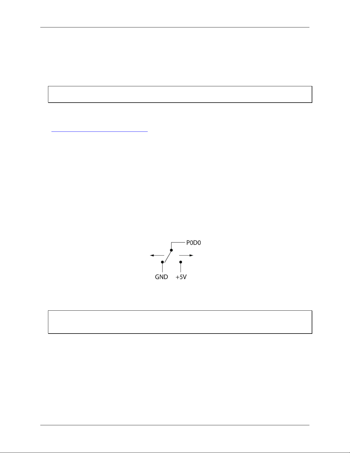
The digital I/O terminals can detect the state of any TTL-level input signal with CMOS output. Refer to the
schematic shown in Figure 4.
Figure 4. Schematic showing switch detection by digital channel P0D0
If you set the switch to the +5 V input, the digital bit reads TRUE (1). If you move the switch to GND, the bit
reads FALSE (0).
Hardware compatibility
The E-DIO24-OEM is functionally equivalent to USB-DIO24 Series and USB-1024 Series hardware. Software
programs written for those hardware devices can be run with the E-DIO24-OEM.
12
Page 13
E-DIO24-OEM User's Guide Functional Details
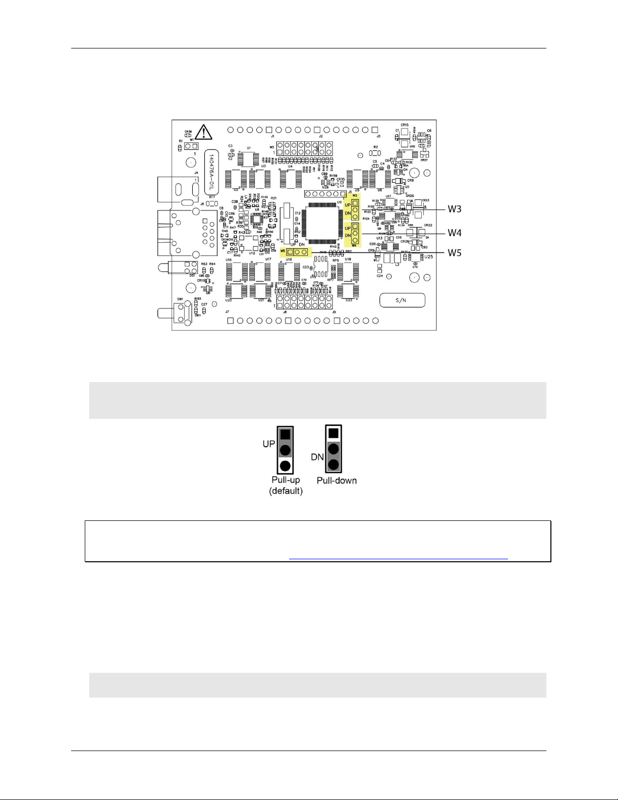
Pull-up/down configuration
All DIO lines are pulled high by default to 5 V through 47 kΩ resistors via jumpers W3, W4, and W5 (see
Figure 5 below). Each jumper configures a digital port for pull-up or pull-down.
Figure 5. W3 jumper location
The pull-up/down voltage is common to all 47 kΩ resistors. Each jumper is configured by default for pull-up.
Figure 6 below shows the jumper configured for pull-up and pull-down.
Caution! The discharge of static electricity can damage some electronic components. Before touching the
board, ground yourself using a wrist strap or touch the computer chassis or other grounded object
to eliminate any stored static charge.
Figure 6. Pull-up/down jumper configurations, typical
For more information about digital signal connections
For general information about digital signal connections and digital I/O techniques, refer to the Guide to DAQ
Signal Connections (available on our web site at www.mccdaq.com/pdfs/DAQ-Signal-Connections.pdf).
Counter input
The 32-bit event counter is accessed with digital port 2 bit 7 (P2D7). This pin accepts a frequency input up to
10 MHz. The internal counter increments when the TTL levels transition from low to high.
Voltage output
The +VO terminal can output up to 10 mA maximum. You can use this terminal to supply power to external
devices or circuitry.
Caution! The +VO terminal is an output. Do not connect to an external power supply or you may damage
the device and possibly the computer.
13
Page 14

E-DIO24-OEM User's Guide Functional Details
Ground
The ground (GND) terminals provide a common ground for the digital I/O, counter input, and power output
terminal.
Mechanical drawings
Figure 7. E-DIO24-OEM device circuit board dimensions
14
Page 15

Parameter
Specification
Digital type
5 V TTL input / CMOS output
Number of I/O
24, configured as 3 ports of 8 bits each (Port 0, Port 1, Port 2)
Configuration
Each bit can be independently configured for input or output
Pull-up configuration
Each port has 47 kΩ resistors configurable as pull-up (default) or pull-down via
internal jumpers W3 (port 1), W4 (port 2), and W5 (port 0).
Digital I/O transfer rate
(system-paced)
100 to 5000 reads/writes per second, typical, on a local network (Note 1)
Alarm functionality
Any combination of DIO bits may be configured to become outputs and go to defined
values when an Ethernet connection with a host is established or lost.
Power on and reset state
All bits are input unless the alarm functionality is enabled for them.
Input high voltage threshold
2.0 V min (Note 2)
Input high voltage limit
5.5 V absolute max
Input low voltage threshold
0.8 V max (Note 2)
Input low voltage limit
–0.5 V absolute min
0 V recommended min
Output high voltage
4.4 V min (IOH = –50 µA)
3.76 V min (IOH = –24 mA)
Output low voltage
0.1 V max (IOL = 50 µA)
0.44 V max (IOL = 24 mA)
Specifications
All specifications are subject to change without notice.
Typical for 25 °C unless otherwise specified.
Specifications in italic text are guaranteed by design.
Digital input/output
Table 1. Digital input/output specifications
Chapter 4
Note 1: This is the typical throughput when the device and host are both connected by Ethernet to the same
local network. Throughput can vary significantly, and typical throughput is not guaranteed, if a
wireless connection is involved or data is sent over the internet.
Note 2: The digital input thresholds (P2D7 only) and counter input thresholds are different due to different
buffer types.
15
Page 16

E-DIO24-OEM User's Guide Specifications
Parameter
Specification
Pin name
P2D7 (shared with digital I/O)
Counter type
Event counter
Number of channels
1
Input type
Schmitt trigger; uses port 2 digital I/O pull-up/down selection.
Resolution
32 bits
Schmitt trigger hysteresis
1.01 V typ
0.6 V min
1.5 V max
Input high voltage threshold
2.43 V typ (Note 3)
1.9 V min
3.1 V max
Input high voltage limit
5.5 V absolute max
Input low voltage threshold
1.42 V typ (Note 3)
1.0 V min
2.0 V max
Input low voltage limit
–0.5 V absolute min
0 V recommended min
Input frequency
10 MHz max
High pulse width
50 ns min
Low pulse width
50 ns min
Parameter
Specification
Non-volatile memory
4,096 bytes (272 bytes for settings, 3,824 bytes for user)
Parameter
Condition
Specification
External power supply
5 V ±5% required
5 V, 1 A supply recommended (PS-5V1AEPS)
Supply current
Quiescent current
160 mA typical (Note 4)
840 mA max, including all external loading
User output voltage range
Available at +VO pin
4.40 V min to 5.25 V max; assumes recommended AC
adapter is used
User output current
Available at +VO pin
10 mA max
Counter
Table 2. Counter specifications
Note 3: The digital input thresholds (P2D7 only) and counter thresholds are different due to different buffer
types.
Memory
Table 3. Memory specifications
Power
Table 4. Power specifications
Note 4: This is the total quiescent current requirement for the device that includes the LEDs. This value does
not include any potential loading of the digital I/O bits or +VO pin.
16
Page 17

E-DIO24-OEM User's Guide Specifications
Parameter
Specification
Ethernet type
100 Base-TX
10 Base-T
Communication rates
10/100 Mbps, auto-negotiated
Connector
RJ-45, 8 position
Cable length
100 meters (328 feet) max
Additional parameters
HP Auto-MDIX support
Parameter
Specification
Protocols used
TCP (IPv4 only) and UDP
Network ports used
UDP: 54211 (discovery)
UDP: 6234 (bootloader only)
TCP: 54211 (commands)
Network IP configuration
DHCP + link-local, DHCP, static, link-local
Network name
E-DIO24-xxxxxx, where xxxxxx are the lower 6 digits of the device MAC
address
Network name publication
By NBNS; responds to b-node broadcasts, therefore only available on the local subnet
Parameter
Specification
Factory default IP address
192.168.0.101
Factory default subnet mask
255.255.255.0
Factory default Gateway
192.168.0.1
Factory default DHCP setting
DHCP + link-local enabled
Parameter
Specification
Security implementation
TCP sockets are not opened unless application sends the correct PIN connection
code; stored in non-volatile memory; may be changed by user; default value is 0000
Number of concurrent sessions
1
Vulnerabilities
TCP Sequence Number Approximation Vulnerability
Network
Ethernet connection
Table 5. Ethernet connection specifications
Network interface
Table 6. Factory default specifications
Network factory default settings
Table 7. Factory default specifications
Network security
Table 8. Factory default specifications
17
Page 18

E-DIO24-OEM User's Guide Specifications
Parameter
Specification
Power LED (top)
4.2 V < V
ext
< 5.6 V: On
V
ext
< 4.2 V, V
ext
> 5.6 V: Off (power fault)
Both LEDs blinking continuously: In firmware update mode
Activity LED (bottom)
On when there is a valid host connection.
Blinks when a command is received.
Both LEDs blinking continuously: In firmware update mode.
Ethernet connector LEDS
Left (green) – Link/activity indicator: on when there is a valid Ethernet link, and
blinks when network activity is detected.
Right (yellow) – Speed indicator: on for 100 Mbps, off for 10 Mbps or no link.
Factory reset button
Resets network and alarm configuration settings to factory default values.
Press and hold for 4 seconds. The Power and Activity LEDs will both blink twice
and turn off to indicate that network settings have been restored to default values.
Release the button to allow the device to reset and use the default settings.
If the reset button is released before the two LEDs blink, settings are not affected.
Holding the reset button at power on forces the device into firmware update mode
in case of a failed firmware update. In this mode, both LEDs blink together
constantly. The device may be returned to normal operation by cycling the power.
Parameter
Specification
Operating temperature range
0 °C to 55 °C max
Storage temperature range
–40 °C to 85 °C max
Humidity
0% to 90% non-condensing max
Parameter
Specification
Dimensions (L × W × H)
101.35 × 76.71 × 14.61 mm (3.99 × 3.02 × 0.575 in.) max
Parameter
Specification
I/O connector type
Two 2 × 8 pin 0.1 in. pitch headers labeled W2 and W6
Power connector type
DC barrel input jack labeled J4 (mates with 5.5 mm OD / 2.1 mm ID plug, center
positive)
1×2 pin 0.1 in. pitch header labeled W1 (pin 1: positive input)
LED displays and the factory reset button
Table 9. LED and button configurations
Environmental
Mechanical
Header connector
Table 10. Environmental specifications
Table 11. Mechanical specifications
Table 12. Header connector specifications
18
Page 19

E-DIO24-OEM User's Guide Specifications
Pin
Signal name
Pin description
Pin
Signal name
Pin description
1
P0D0
Port 0 bit 0
2
P0D1
Port 0 bit 1
3
P0D2
Port 0 bit 2
4
P0D3
Port 0 bit 3
5
GND
Ground
6
P0D4
Port 0 bit 4
7
P0D5
Port 0 bit 5
8
P0D6
Port 0 bit 6
9
P0D7
Port 0 bit 7
10
GND
Ground
11
GND
Ground
12
P2D0
Port 2 bit 0
13
P2D1
Port 2 bit 1
14
P2D2
Port 2 bit 2
15
P2D3
Port 2 bit 3
16
GND
Ground
Pin
Signal name
Pin description
Pin
Signal name
Pin description
1
P1D0
Port 1 bit 0
2
P1D1
Port 1 bit 1
3
P1D2
Port 1 bit 2
4
P1D3
Port 1 bit 3
5
GND
Ground
6
P1D4
Port 1 bit 4
7
P1D5
Port 1 bit 5
8
P1D6
Port 1 bit 6
9
P1D7
Port 1 bit 7
10
+VO
User voltage output
11
GND
Ground
12
P2D4
Port 2 bit 4
13
P2D5
Port 2 bit 5
14
P2D6
Port 2 bit 6
15
P2D7
Port 2 bit 7 / Counter
16
GND
Ground
Parameter
Specification
Connector type
3.51 mm screw terminal footprints (not populated), labeled J1, J2, J3, J7, J8, J9
J1
J7
Pin
Signal name
Pin description
Pin
Signal name
Pin description
5
P1D0
Port 1 bit 0
1
P0D0
Port 0 bit 0
4
P1D1
Port 1 bit 1
2
P0D1
Port 0 bit 1
3
P1D2
Port 1 bit 2
3
P0D2
Port 0 bit 2
2
P1D3
Port 1 bit 3
4
P0D3
Port 0 bit 3
1
GND
Ground
5
GND
Ground
6 P0D4
Port 0 bit 4
J2
J8
Pin
Signal name
Pin description
Pin
Signal name
Pin description
5
P1D4
Port 1 bit 4
1
P0D5
Port 0 bit 5
4
P1D5
Port 1 bit 5
2
P0D6
Port 0 bit 6
3
P1D6
Port 1 bit 6
3
P0D7
Port 0 bit 7
2
P1D7
Port 1 bit 7
4
GND
Ground
1
+VO
User voltage output
5
GND
Ground
J3
J9
Pin
Signal name
Pin description
Pin
Signal name
Pin description
6
GND
Digital ground
1
P2D0
Port 2 bit 0
5
P2D4
Port 2 bit 4
2
P2D1
Port 2 bit 1
4
P2D5
Port 2 bit 5
3
P2D2
Port 2 bit 2
3
P2D6
Port 2 bit 6
4
P2D3
Port 2 bit 3
2
P2D7
Port 2 bit 7 / Counter
5
GND
Ground
1
GND
Ground
Table 13. W6 pinout
Table 14. W2 pinout
Screw terminal connector (not populated)
Table 15. Screw terminal connector specifications
Table 16. Screw terminal pinout
19
Page 20

E-DIO24-OEM User's Guide Specifications
20
Page 21

Measurement Computing Corporation
10 Commerce Way
Norton, Massachusetts 02766
(508) 946-5100
Fax: (508) 946-9500
E-mail: info@mccdaq.com
www.mccdaq.com
NI Hungary Kft
H-4031 Debrecen, Hátar út 1/A, Hungary
Phone: +36 (52) 515400
Fax: +36 (52) 515414
http://hungary.ni.com/debrecen
 Loading...