

Measurement Computing DaqBoard/300o, DaqBoard/3000, DaqBoard/3001, DaqBoard/3005, DaqBoard/3006 User Manual
Page 1

DaqBoard/3000, /3001, /3005, and /3006
PCI 16-Bit, 1-MHz
Multifunction Boards
Measurement Computing
10 Commerce Way
Norton, MA 02766
(508) 946-5100
Fax: (508) 946-9500
info@mccdaq.com
www.mccdaq.com
DaqBoard/3000 Series
USER’S MANUAL
*372563C-01*
372563C-01 1128-0901 rev 1.4
Page 2

Warranty Information
Contact Measurement Computing by phone, fax, or e-mail in regard to warranty-related issues:
Phone: (508) 946-5100, fax: (508) 946-9500, e-mail: info@mccdaq.com
Many Measurement Computing products carry the CE marker indicating they comply with the safety and emissions
standards of the European Community. When applicable these products have a Declaration of Conformity stating which
specifications and operating conditions apply. You can view the Declarations of Conformity at
www.mccdaq.com/legal.aspx (CE Information page).
Refer all service to qualified personnel. This caution symbol warns of possible personal injury or equipment damage
under noted conditions. Follow all safety standards of professional practice and the recommendations in this manual.
Using this equipment in ways other than described in this manual can present serious safety hazards or cause equipment
damage.
This warning symbol is used in this manual or on the equipment to warn of possible injury or death from electrical
shock under noted conditions.
This ESD caution symbol urges proper handling of equipment or components sensitive to damage from electrostatic
discharge. Proper handling guidelines include the use of grounded anti-static mats and wrist straps, ESD-protective bags
and cartons, and related procedures.
This symbol indicates the message is important, but is not of a Warning or Caution category. These notes can be of great
benefit to the user, and should be read.
In this manual, the book symbol always precedes the words “Reference Note.” This type of note identifies the location
of additional information that may prove helpful. References may be made to other chapters or other documentation.
Tips provide advice that may save time during a procedure, or help to clarify an issue. Tips may include additional
reference.
Limitation of Liability
Measurement Computing cannot be held liable for any damages resulting from the use or misuse of this product.
Copyright, Trademark, and Licensing Notice
All Measurement Computing documentation, software, and hardware are copyright with all rights reserved. No part of
this product may be copied, reproduced or transmitted by any mechanical, photographic, electronic, or other method
without Measurement Computing’s prior written consent. IOtech product names are trademarked; other product names, as
applicable, are trademarks of their respective holders. All supplied IOtech software (including miscellaneous support
files, drivers, and sample programs) may only be used on one installation. You may make archival backup copies.
CE Notice
Warnings, Cautions, Notes, and Tips
Specifications and Calibration
Specifications are subject to change without notice. Significant changes will be addressed in an addendum or revision to
the manual. As applicable, the hardware is calibrated to published specifications. Periodic hardware calibration is not
covered under the warranty and must be performed by qualified personnel as specified in this manual. Improper
calibration procedures may void the warranty.
Page 3

⇒
CAUTION
Using this equipment in ways other than describe d in this manual can cause
personal injury or equipment damage. Before setting up and using your
equipment, you should read all documentation that covers your system.
Pay special attention to Warnings and Cautions.
Note:
During software installation, Ado be
®
PDF versions of user manuals will a utomatically
install onto your hard drive as a par t of product support. The default location is in the
Programs group, which can be accessed from the Windows Desktop. Initial navigation
is as follows:
Start [on Desktop]
All Programs ⇒ IOtech …
Refer to the PDF documentation for information regarding hardware and software.
Page 4

Table of Contents
DaqBoard/1000 /2000 /3000 Series, Inst allation Guide (p/n 1033-0940)
1 – Device Overviews
Block Diagrams ….. 1-1
Connections …… 1-2
Theory of Operation…… 1-3
Daq Software …… 1-13
2 – Connections and Pinouts
Overview …… 2-1
Pinout for DaqBoard/3000 Series Boards …… 2-2
TB-100 Terminal Connector Option …… 2-3
PDQ30 Analog Expansion and DBK215 Connector Options …… 2-4
3 – CE-Compliance
Overview …… 3-1
Safety Conditions …… 3-1
Emissions/Immunity C o n d itions …… 3-2
CE Rules of Thumb …… 3-2
Noise Considerations …… 3-3
4 – Calibration
5 – Counter Input Modes
Debounce Module …… 5-1
Terms Applicable to Cou n ter Modes…….5-5
Counter Options …… 5-5
Counter/Totalize Mode …… 5-6
Period Mode …… 5-8
Pulsewidth Mode …… 5-11
Timing Mode …… 5-13
Encoder Mode …… 5-15
DaqBoard/3000 Series User’s Manual 937390
Page 5

6 – Setpoint Configuration for O ut put Control
Overview …… 6-1
Detecting Input Values …… 6-3
Controlling Analog, Digi tal, and Timer Outputs …… 6-4
P2C, DAC, or Timer Update Latency …… 6-6
More Exam p les of Control Outputs …… 6-7
Detection on an Analog Input, DAC and P2C Updates …… 6-7
Detection on an Analog Input, Timer Output Updates …… 6-8
Using the Hysteresis Function …… 6-8
Using Multiple Inputs to Control One DAC Output …… 6-10
7 – Specifications - DaqBoard/3000 Seri es and PDQ30
Appendices
Appendix A: DBK215 16-Connector BNC Connection Module
Appendix B: Hardware Analog Level Trigger
An Important Note Regarding Hardware Analog Level Trigger and Comparator Change State
Appendix C:
Glossary
Signal Modes and System Noise
937690 DaqBoard/3000 Series User’s Manual
Page 6
DaqBoard /1000 2000 3000 Series Installation Guide
Before you get started
PCI-bus Data Acquisi t ion Boards
Take ESD precautions!
Verify that you have the following items.
• DaqBoard/1000, /2000, or /3000 Series Device
• Data Acquisition CD
• Monitor: SVGA, 1024 x 768 screen resolution
• Windows 2000 and Windows XP users:
PC with Intel™ Pentium, 1 GHz or equivalent;
128 MB memory; 10 GB disk space
• Windows Vista users:
PC must be Windows Vista Premium Ready
Step 1 - Install Software
IMPORTANT
1. Remove previous version Daq drivers, if present. You can do this through Microsoft’s Add/Remove Programs feature.
2. Insert the Data Acquisition CD into your CD-ROM drive and wait for the CD to auto-run. An Opening
Screen will appear. As an alternative, you can download software from:
3. After the intro-screen appears, follow the screen prompts.
: Software must be installed before installing hardware.
www.iotech.com/ftp.html
Step 2 – Install Boards in availabl e P CI Bus-slots
IMPORTANT: Bus Mastering DMA must be Enabled on the PCI slot [for which the board is to be installed].
Refer to your PC Owner's Manual as needed.
1. Turn off power to, and UNPLUG the host PC and externally connected
equipment.
2. Remove the PC’s cover. Refer to your PC Owner’s Manual as needed.
3. Choose an available PCI bus-slot. Lower residual noise will result by
placing the board in a PCI slot which has vacant adjacent slots.
4. Carefully remove the DaqBoard from its anti-static protective bag. If you
have not already done so, write down the serial number of your board at this
time.
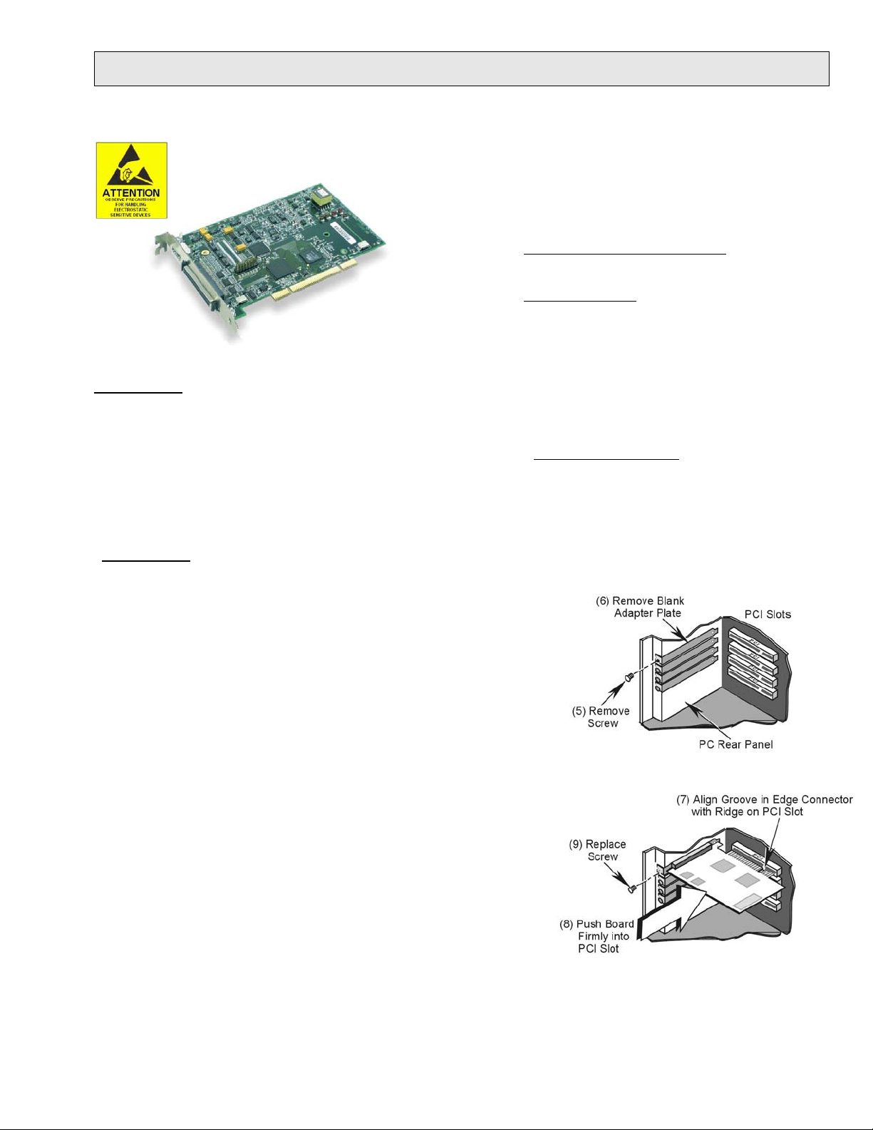
5. Remove the screw that secures the blank adapter plate, which is associated
with the PCI slot you will be using.
6. Remove the blank adapter plate.
7. Align the groove in the board’s PCI edge-connector with the ridge of the
desired PCI slot, and with the PC’s corresponding rear-panel slot.
8. Push the board firmly into the PCI slot. The board will snap into position.
9. Secure the board by inserting the rear-panel adapter-plate screw.
10. Using the previous steps, install additional boards into available PCI bus-
slots, if applicable to your application.
11. Replace the computer’s cover.
12. Plug in all cords and cables that were removed in step 1.
13. Apply power to, and start up the PC.
1033-0940, rev 9.0 324324B-01 Printed in Hungary
Page 7

Step 3 – Configure Boards
Measurement Computing
10 Commerce Way
Norton, MA 02766
(508) 946-5100
Fax: (508) 946-9500
info@mccdaq.com
www.mccdaq.com
1. Run the Daq Configuration control panel applet. Navigation from the desktop to the applet is as follows:
⇒ Settings ⇒ Control Panel ⇒ DaqConfiguration (double-click).
Start
2. Double-click on the Device Inventory’s DaqBoard icon (1K0, 2K0, or 3K0, as applicable).
ONLY IF the board’s icon is not present, perform A, B, and C, otherwise go directly to step 3.
(A) After accessing t he Daq Conf i guration control panel applet, cl i c k on the <Add Device> button.
(B) Using the Device Type’s pull-down list , select the applicable board.
(C) Click the <OK> button. The board’s Properti es tab will appear. At this point, complete steps 3 through 5.
3. Enter a “Device Name” in the text box, or use the default, e.g., DaqBoard2K0. The Name is for identifying the
specific DaqBoard, but actually refers to the PCI slot.
4. Verify that the “Device Type” shows the correct board, e.g., “DaqBoard/1000, DaqBoard/2001, etc.”
Note that available device types can be viewed via the pull-down list.
5. Confirm that the DaqBoard’s text box shows a Bus #, Slot #, and Serial Number. If this text box is empty, use its
pull-down list and select the serial number that matches the one for your board.
Step 4 – Test Hardware
Use the following steps to test the DaqBoard. Note that these steps are continued from those listed under the previous
section, “Configure Boards.”
1. Select the “Test Hardware” tab.
2. Click the “Resource Test” button.
3. After the test is complete, click “OK.” System capability is now tested; and test results are displayed.
Note: If you experience difficulties, please consult your user documentation (included on your CD) before calling for
technical support.
Step 5 – Connect Signals
For /1000 Series and /3000 Series boards, connection is typically made via a terminal board, such as the optional TB-100,
a DBK215 module via a 68-pin SCSI connector and/or or a PDQ30 via a HDMI connector. Note that the DaqBoard/3006
has no HDMI connector and cannot be connected to a PDQ30. The user’s manual, included on the Data Acquisition CD
and also available on our website, contains detailed information, including specifications, pinouts, and numerous
illustrations.
Note that /2000 Series
information regarding the DBK200 Series, refer to the DBK Option Cards and Modules User’s Manual (p/n 457-0905).
A copy is included on the Data Acquisition CD and on our website.
Reference Notes:
During software installation, Adobe PDF versions of user manuals are automatically installed onto your hard
drive as a part of product support. The default location is in the Programs group, which can be accessed
from the Windows Desktop. The documents can also be read directly from the CD. You will need Adobe
Acrobat or the Acrobat Reader.
boards typically make use of a DBK200 Series option for connecting signals. For detailed
*324324B-01*
324324B-01
Printed in Hungary
Page 8

Device Overviews 1
Block Diagrams …… 1-1
Connections …… 1-2
Product Features …… 1-3
Software ……1-13
DaqView can only be used with one DaqBoard at a time. DASYLab and LabView can be
used with multiple boards. For multiple board use (via custom programming) refer to the
Using Multiple Devices section of the Programmer’s Manual.
Reference Note:
Programming topics are covered in the Programmer’s User Manual (p/n 1008-0901). As a part
of product support, this manual is automatically loaded onto your hard drive during software
installation. The default location is the Programs group, which can be accessed through the
Windows Desktop.
Reference Note:
For board details refer to Chapter 6, Specifications.
Block Diagrams
Block Diagram for DaqBoard/3000 and /3001
Note: DaqBoard/3000 has two 16-Bit Digital-to-Analog Converters.
DaqBoard/3001 has four 16-Bit Digital-to-Analog Converters.
DaqBoard/3000 Series User’s Manual 988093 Daq Systems and Device Overviews 1-1
Page 9

Connections
SCSI - 68 pin
CA-G55 68-conductor ribbon expansion cable. 3 feet.
CA-G56 68-conductor shielded expansion cable. 3 feet.
CA-G56-6 68-conductor shielded expansion cable. 6 feet.
Block Diagram for DaqBoard/3005 and /3006
* Note: DaqBoard/3006 has 16 single-ended analog inputs; ±10V input range only;
it has no differential input. DaqBoard/3006 has no HDMI interface.
Reference Note:
For the DaqBoard/3000 Series installation procedure, refer to the DaqBoard Installation
Guide (1033-0940). A copy of the guide is included at the beginning of this manual.
All input and output signals are available at the 3000 Series board’s 68-pin SCSI
connector. Chapter 2 includes a pinout. A TB-100 screw-terminal board or a DBK215
BNC / screw-terminal module can be used to make all signal I/O connections. Either of
these two termination options can be connected to the DaqBoard/3000 Series SCSI
connector via one of the following cables.
HDMI
1-2 Daq Systems and Device Overviews
The HDMI connector can be used to connect a PDQ30 analog expansion module
to a DaqBoard/3000 Series board. Details are provided in Chapter 2 of this manual.
Cable CA-266-3 (3 ft.) [or CA-266-6 (6 ft.)] is used to connect the PDQ30 to the 3000
Series board.
The HDMI connector is not present on DaqBoard/3006.
988093 DaqBoard/3000 Series User’s Manual
Page 10

Product Features
I/O Comparison Matrix
Product or System Analog Input
Channels
DaqBoard/3000 16SE / 8DE 7 2 24 4 2
DaqBoard/3001 16SE / 8DE 7 4 24 4 2
DaqBoard/3005 16SE / 8DE 7 0 24 4 2
DaqBoard/3006 16SE only 1 0 24 4 2
DaqBoard/3000 with
PDQ30
DaqBoard/3001
with PDQ30
DaqBoard/3005
with PDQ30
64SE / 32DE 7 2 24 4 2
64SE / 32DE 7 4 24 4 2
64SE / 32DE 7 0 24 4 2
Input
Ranges
Analog
Output
Channels
Digital I/O
Channels
Counter
Inputs
Timer
Outputs
The DaqBoard/3000 Series boards feature a 16-bit/1-MHz A/D converter, 16 analog input channels [user
expandable up to 64], up to four 16-bit/1-MHz analog outputs, 24 high-speed digital I/O channels, 2 timer
outputs, and four 32-bit counters.
All analog I/O, digital I/O, and counter/timer I/O can operate synchronously and simultaneously,
guaranteeing deterministic I/O timing amongst all signal types. The DaqBoard/3000 Series boards include
a high-speed, low-latency, highly deterministic control output mode that operates independent of the PC. In
this mode both digital and analog outputs can respond to analog, digital and counter inputs as fast as 2µsec.
Other Hardware Features Include:
o Encoder measurements up to 20 MHz, including Z-channel zeroing
o Frequency and Pulse-width measurements with 20.83 nsec resolution
o Timing mode: can measure the time between two counter inputs to 20.83 nsec resolution
o Self-calibration
The DaqBoard/3000 series offers up to 12-MHz scanning of all digital input lines. Digital inputs and
counter inputs can be synchronously scanned [along with analog inputs] but do not affect the overall A/D
rate because they use no time slot in the scanning sequencer. For example, one analog input can be scanned
at the full 1-MHz A/D rate along with digital and counter input channels. The 1-MHz A/D rate is
unaffected by additional digital and counter channels.
Adding analog input channels to a DaqBoard/3000 Series board is easy. An additional 48 single-ended
[or 24 differential] analog input channels can be added to each board with the optional PDQ30 expansion
module.* The PDQ30 connects to the Daqboard/3000 series card via an external cable. With the
DaqBoard/3000’s 1-MHz aggregate sample rate, users can easily add multiple analog expansion channels
and still have enough bandwidth to have a per-channel sample rate in the multiple kHz range.
DaqBoard/3006 does not support PDQ30.
*
DaqBoard/3000 Series User’s Manual 988093 Daq Systems and Device Overviews 1-3
Page 11

Signal I/O
One 68-pin connector provides access to the 16SE/8DE analog input channels, 24 digital I/O lines,
counter/timer channels, and analog outputs (when applicable). With exception of DaqBoard/3006, a
HDMI connector is also located on the orb. The HDMI provides connection for channel expansion with
the PDQ30.
Analog Input
The DaqBoard/3000 series has a 16-bit, 1-MHz A/D coupled with 16 single-ended, or 8 differential
analog inputs. Seven software programmable ranges provide inputs from ±10V to ±100 mV full scale [with
exception of DaqBoard/3006 which has a fixed single-ended range of ±10V.] Each channel can be
software-configured for a different range, as well as for single-ended or differential bipolar input.
Synchronous I/O
The DaqBoard/3000 series has the ability to make analog measurements and scan digital and counter
inputs, while synchronously generating up to four analog outputs.
Additionally, while digital inputs and counter inputs can be synchronously scanned along with analog
inputs, they do not affect the overall A/D rate because they use no time slot in the scanning sequencer. For
example, one analog input can be scanned at the full 1-MHz A/D rate along with digital and counter input
channels. The 1-MHz A/D rate is unaffected by the additional digital and counter channels.
Orb with HDMI and 68-Pin SCSI Connectors
Note: The HDMI connector is not present on the DaqBoard/3006.
Input Scanning
DaqBoard/3000 Series devices have several scanning modes to address a wide variety of applications. A
512-location scan buffer can be loaded by the user with any combination of analog input channels. All
analog input channels in the scan buffer are measured sequentially at 1 µsec per channel. The user can also
specify that the sequence repeat immediately, or repeat after a programmable delay from 0 to 19 hours,
with 20.83 nsec resolution. For example, in the fastest mode, with a 0 delay, a single analog channel can
be scanned continuously at 1 Msamples/s; two analog channels can be scanned at 500K samples/seach;
16 analog input channels can be scanned at 62.5 Ksamples/s.
The digital and counter inputs can be read in several modes. First, via software the digital inputs or
counter inputs can be read asynchronously at anytime before, during, or after an analog input scan
sequence. This software mode is not deterministic as to exactly when a digital or counter input is read
relative to an analog input channel.
In either of the two synchronous modes, the digital inputs and/or counter inputs are read with deterministic
time correlation to the analog inputs. In the once-per-scan mode, all of the enabled digital inputs and
counter inputs are read during the first analog measurement of an analog input scan sequence. The
advantage of this mode is that the digital and counter inputs do not consume an analog input time slot, and
therefore do not reduce the available bandwidth for making analog input measurements. For example,
presume all 24 bits of digital input are enabled, and all four 32-bit counters are enabled, and eight channels
of analog inputs are in the scan sequence at full 1µsec/channel rate. At the beginning of each analog input
scan sequence, which would be 8 µsec in total duration, all digital inputs and counter inputs will be
measured and sent to the PC during the first µsec of the analog scan sequence.
1-4 Daq Systems and Device Overviews
988093 DaqBoard/3000 Series User’s Manual
Page 12
Another synchronous mode allows digital inputs to be scanned every time an analog input channel is
scanned. For example, if eight analog inputs are scanned at 1 µsec per channel continuously, and 24 bits of
digital inputs are enabled, then the 24 bits of digital inputs will be scanned at 24 bits per 1 µsec. If counters
are enabled in this mode, they will be scanned at once per scan, in the same manner as in the first example
above.
Note: It is not necessary to read counters as often as it is to read digital inputs. This is because counters
continue to count pulses regardless of whether or not they are being read by the PC.
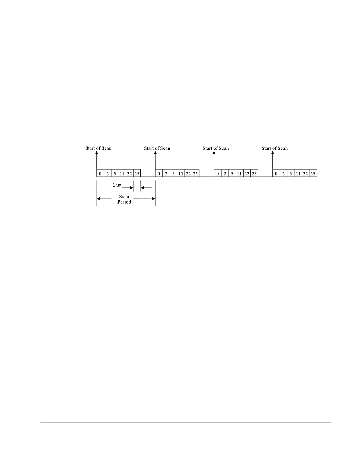
Example 1: Analog channel scanning of voltage inputs
The figure below shows a simple acquisition. The scan is programmed pre-acquisition and is made up of 6
analog channels (Ch0, Ch2, Ch5, Ch11, Ch22, Ch25.) Each of these analog channels can have a different
gain. The acquisition is triggered and the samples stream to the PC via DMA. Each analog channel
requires one microsecond of scan time therefore the scan period can be no shorter than 6 us for this
example. The scan period can be made much longer than 6 us, up to 19 hours. The maximum scan
frequency is one divided by 6us or 166,666 Hz.
Notice that some of the analog channels in the scan group are from a PDQ30 expansion module. All
analog channels are sampled at the same rate of 1us. Analog channels on the PDQ30 can also have any of
the gain ranges applied.
DaqBoard/3000 Series User’s Manual 988093 Daq Systems and Device Overviews 1-5
Page 13

Example 2: Analog channel scanning of voltage and temperature inputs
The figure below shows a more complicated acquisition. The scan is programmed pre-acquisition and is
made up of 6 analog channels (Ch0, Ch2, Ch5, Ch11, Ch22, Ch23.) Each of these analog channels can
have a different gain. Two of the channels (22 and 23) are from a PDQ30 expansion module. These two
channels can be programmed to directly measure thermocouples. In this mode, oversampling is
programmable up to 256 oversamples per channel in the scan group. When oversampling is applied, it is
applied to all analog channels in the scan group, including temperature and voltage channels. (Digital
channels are not oversampled.) If the desired number of oversamples is 256 then each analog channel in
the scan group will take 256 microseconds, the returned 16-bit value represents an average of 256
consecutive 1us samples of that channel. The acquisition is triggered and 16-bit values (each representing
an average of 256) stream to the PC via DMA.
Since two of the channels in the scan group are temperature channels, the acquisition engine will be
required to read a cold-junction-compensation (CJC) temperature every scan. In fact, depending upon
which PDQ30 channels are being used for temperature, there may be a CJC temperature required for each
temperature channel in the scan. Each 4 channel terminal block of the PDQ30 shares one CJC so if all
temperature channels are grouped on one (of the six) terminal blocks, then only one CJC temperature
measurement will need to be made per scan. For every PDQ30 terminal block that is measuring at least
one temperature channel, one additional CJC temperature measurement will be automatically added to the
scan group. This increases the scan period and reduces the maximum scanning frequency.
In this example, the desired number of oversamples is 256, therefore each analog channel in the scan group
requires 256 microseconds to return one 16-bit value. The oversampling is also done for CJC temperature
measurement channels. The minimum required scan period for this example is therefore 7 X 256 us or
1792 microseconds. The maximum scan frequency is the inverse of this number, 558 Hz.
Autozero may also be employed. This adds more channels to the scan group and further reduces the
maximum scan frequency. Auto zero channels read a shorted analog input that is internal to the PDQ30.
Auto zeroing reduces drift due to fluctuating ambient temperatures or ambient temperatures outside the DC
specifications.
1-6 Daq Systems and Device Overviews
988093 DaqBoard/3000 Series User’s Manual
Page 14
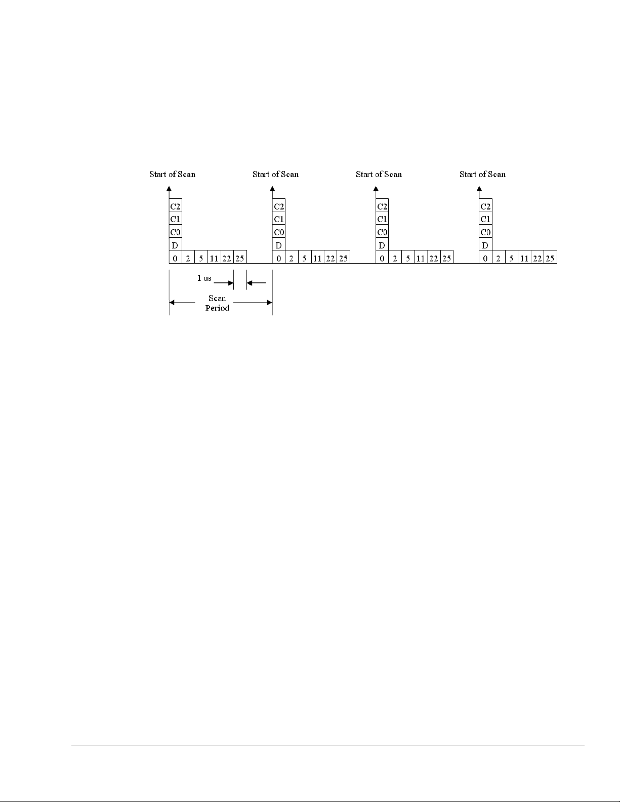
Example 3: Analog and digital channel scanning, once per scan mode
The figure below shows a more complicated acquisition. The scan is programmed pre-acquisition and is
made up of 6 analog channels (Ch0, Ch2, Ch5, Ch11, Ch22, Ch25) and 4 digital channels (16-bits of
digital IO, 3 counter inputs.) Each of the analog channels can have a different gain and each of the counter
channels can be put into a different mode (totalizing, pulsewidth, encoder, etc.) The acquisition is
triggered and the samples stream to the PC via DMA. Each analog channel requires one microsecond of
scan time therefore the scan period can be no shorter than 6 us for this example. All of the digital channels
are sampled at the start of scan and do not require additional scanning bandwidth as long as there is at least
one analog channel in the scan group. The scan period can be made much longer than 6 us, up to 19 hours.
The maximum scan frequency is one divided by 6us or 166,666 Hz.
The counter channels could be returning only the lower 16-bits of count value if that is sufficient for the
application. They could also be returning the full 32-bit result if necessary. Similarly, the digital input
channel could be the full 24 bits if desired or only 8 bits if that is sufficient. If the 3 counter channels are
all returning 32 bit values and the digital input channel is returning a 16 bit value, then 13 samples are
being returned to the PC every scan period, each sample being 16-bits. 32-bit counter channels are divided
into two 16-bit samples, one for the low word and the other for the high word. If the maximum scan
frequency is 166,666 Hz then the data bandwidth streaming into the PC is 2.167 MSamples per second.
Some slower PCs may have a problem with data bandwidths greater than 6 MSamples per second.
DaqBoard/3000 Series User’s Manual 988093 Daq Systems and Device Overviews 1-7
Page 15

Example 4: Sampling digital inputs for every analog sample in a scan group
The figure below shows another acquisition. The scan is programmed pre-acquisition and is made up of 6
analog channels (Ch0, Ch2, Ch5, Ch11, Ch22, Ch25) and 4 digital channels (16-bits of digital input, 3
counter inputs.) Each of the analog channels can have a different gain and each of the counter channels
can be put into a different mode (totalizing, pulsewidth, encoder, etc.) The acquisition is triggered and the
samples stream to the PC via DMA. Each analog channel requires one microsecond of scan time therefore
the scan period can be no shorter than 6 us for this example. All of the digital channels are sampled at the
start of scan and do not require additional scanning bandwidth as long as there is at least one analog
channel in the scan group. The 16-bits of digital input are sampled for every analog sample in the scan
group. This allows up to 1MHz digital input sampling while the 1MHz analog sampling bandwidth is
aggregated across many analog input channels. The scan period can be made much longer than 6 us, up to
19 hours. The maximum scan frequency is one divided by 6us or 166,666 Hz. Note that digital input
channel sampling is not done during the “dead time” of the scan period where no analog sampling is being
done either.
If the 3 counter channels are all returning 32 bit values and the digital input channel is returning a 16 bit
value, then 18 samples are being returned to the PC every scan period, each sample being 16-bits. 32-bit
counter channels are divided into two 16-bit samples, one for the low word and the other for the high word.
If the maximum scan frequency is 166,666 Hz then the data bandwidth streaming into the PC is 3
MSamples per second. Some slower PCs may have a problem with data bandwidths greater than 6
MSamples per second.
Analog Input & Channel Expansion
The DaqBoard/3000 series has a 16-bit, 1-MHz A/D coupled with 16 single-ended, or 8 differential analog
inputs. Seven software programmable ranges provide inputs from ±10V to ±100 mV full scale. Each
channel can be software-configured for a different range, as well as for single-ended or differential bipolar
input. A hybrid PGIA on the boards is guaranteed to settle to the specified accuracy while operating at the
full 1 Msample/s rate.
Adding additional analog input channels to the /3000 series boards is easy with the optional PDQ30
expansion module. The PDQ30 connects to the board via cable and does not consume a PCI slot. PDQ30
adds an additional 48 single-ended or [24 differential-ended] analog inputs for a total channel capacity of
64 single-ended [or 32 differential] inputs.
Measurement speed of PDQ30 channels is the same 1 Msample/s exhibited by the /3000 board channels.
The DaqBoard/3000 Series supports up to four boards per PC, effectively quadrupling the number of
channels.
The PDQ30 attaches via the CA-266-3 cable to the HDMI expansion connector on the orb of the
DaqBoard, with exception of the DaqBoard/3006.*
DaqBoard/3006 has no HDMI connector and is intended for small channel applications for which expansion is not a
*
desired option.
1-8 Daq Systems and Device Overviews
988093 DaqBoard/3000 Series User’s Manual
Page 16

Bus Mastering DMA
The DaqBoard/3000 series supports Bus Mastering DMA. Multiple DMA channels allow analog and
digital/counter input data, as well as analog and digital output data to flow between the PC and the
DaqBoard/3000 series without consuming valuable CPU time. The driver supplied with the
DaqBoard/3000, as well as all other third-party software support such as LabVIEW®, automatically
utilize Bus Mastering DMA to efficiently conduct I/O from the PC to the DaqBoard.
Triggering
Triggering can be the most critical aspect of a data acquisition application. The DaqBoard/3000 series
supports a full complement of trigger modes to accommodate any measurement situation.
Hardware Analog Triggering
level programmed by the user sets an analog DAC, which is then compared in hardware to the analog input
level on the selected channel. The result is analog trigger latency wh ich is guaranteed to be less than1 µs.
Any analog channel can be selected as the trigger channel, in cluding built-in or PDQ30 expansion
channels. The user can program both the trigger level, as well as the rising or falling edge and hysteresis.
Digital Triggering
latencies guaranteed to be less than 1 µs. Both the logic levels (1 or 0), as well as the rising or falling edge
can be programmed for the discrete digital trigger input.
Pattern Triggering
ability to mask or ignore specific bits.
Software-Based Channel Level Triggering
readings [analog, digital, or counter] are interrogated by the PC in order to detect the trigger event.
Triggering can also be programmed to occur when one of the counters reaches, exceeds, or is within a
programmed window.
. TheDaqBoard/3000 Series uses true analog triggering, whereby the trigger
. A separate digital trigger input line is provided, allowing TTL-level triggering with
. The user can specify a 16-bit digital pattern to trigger an acquisition, including the
. This mode differs from the modes just discussed because the
ed as a trigger source. Triggers can be
Any of the built-in counter/totalizer channels can be program
m
detected on scanned digital input channel patterns as well. Normally software-based triggering results in
long latencies from the moment a trigger condition is detected until the instant data is acquired. However,
theDaqBoard/3000 Series circumvents this undesirable situation by use of pre-trigger data. Specifically,
when software-based-triggering is employed, and the PC detects that a trigger condition has occurred,
(which may be thousands of readings after the actual occurrence of the signal), the DaqBoard driver
automatically looks back to the location in memory, to where the actual trigger-causing measurement
occurred. The acquired data presented to the user begins at the point where the trigger-causing
measurement occurs. The maximum latency in this mode is equal to one scan period
Stop Trigger
. Any of the software trigger modes previously described, including scan count, can be used
to stop an acquisition. Thus an acquisition can be programmed to begin on one event, such as a voltage
level, and then can stop on another event, such as a digital pattern.
Pre-Triggering and Post-Triggering Modes
. Six modes of pre-triggering and post-triggering are
supported, providing a wide variety of options to accommodate any measurement requirement. When
using pre-trigger, the user must use software-based triggering to initiate an acquisition. Th e six modes are:
o No pre-trigger, post-trigger stop event. This, the simplest of modes, acquires data upon receipt of
the trigger, and stops acquiring upon receipt of the stop-trigger event.
h
o Fixed pre-trigger with post-trigger stop event. In t
is mode, the user specifies the number of pre-
trigger readings to be acquired, after which, acquisition continues until a stop-trigger event occurs.
o No
pre-trigger, infinite post-trigger. No pre-t
rigger data is acquired in this mode. Instead, data is
acquired beginning with the trigger event, and is terminated when the operator issues a command
to halt the acquisition.
o Fix
ed pre-trigger with infinite post-trigger. The user speci
fies the amount of pre-trigger data to
acquire, after which the system continues to acquire data until the program issues a command to
halt acquisition.
DaqBoard/3000 Series User’s Manual 988093 Daq Systems and Device Overviews 1-9
Page 17

o Variable pre-trigger with post trigger stop event. Unlike the previous pre-trigger modes, this
mode does not have to satisfy the pre-trigger number of readings before recognizing the trigger
event. Thus the number of pre-trigger readings acquired is variable and dependent on the time of
the trigger event relative to the start. In this mode, data continues to be acquired until the stop
trigger event is detected. Driver support only.
Calibration
riable pre-trigger with infinite post trigger. Thi
o Va
s is similar to the mode described above, except
that the acquisition is terminated upon receipt of a command from the program to halt the
acquisition. Driver support only.
Every range of a DaqBoard/3000 Series device is calibrated at the factory using a digital NIST traceable
calibration method. This method works by storing a correction factor for each range on the unit at the time
of calibration. The user can adjust the calibration of the board while it is installed in the acquisition system.
This does not destroy the factory calibration supplied with the board. This is accomplished by having 3
distinct calibration tables in the DaqBoard/3000 series on-board EPROM, one which contains the factory
cal, and two which are available for user calibration.
e three cal tables provided [factory, user or self-cal tables] by API call or from
The user can select any of t
h
within factory-included software, DaqCal.
i
The user-friendly DaqCal application supports two cal
o Self-cal can be performed aut
omatically in minutes with included software and without the use of
bration modes: Self-Cal and User-Cal.
external hardware or instruments. Self-cal derives its tracebility through an on-board reference
which has a stability of 0.005% per year.
o User-cal is for users that require traceability to international standards such as NIST. A 6-1/2
gital multimeter is required and user calibration software is included with step-by-step
i
d
instructions for full calibration.
Note that a 2-year calibration period is recommended for DaqBoard/3000 Series boards.
Analog Output
DaqBoard/3000 and /3001 Only
DaqBoard/3000 has two 16-bit, 1 MHz analog output channels
The channels have an output range of -10V to +10V. Through the use of Bus Mastering DMA, each D/A
output
on the hard disk. In addition, a program can asynchronously output a value to any of the D/As for nonwaveform applications, presuming that the D/A is not already being used in the waveform output mode.
When used to generate waveforms, the D/As can be cl
separately selected to be clocked from one of the following sources.
. DaqBoard/3001 has four such channels.
can continuously output a waveform at up to 1 MHz. This can be read from PC RAM or from a file
ocked i
n several different modes. Each D/A can be
o Asynchronous Internal Clock
. The on-board programmable clock can generate updates ranging
from 1.5 Hz to 19 hours, independent of any acquisition rate.
o Synchronous Internal Clock
. The rate of analog output update can be synchronized to the
acquisition rate derived from 1 MHz to once every 19 hours.
o Asynchronous External Clock
. A user-supplied external input clock can be used to pace the
D/A, entirely independent of analog inputs.
o Synchronous External Clock
. A user-supplied external input clock can pace both the D/A and
the analog input.
1-10 Daq Systems and Device Overviews
988093 DaqBoard/3000 Series User’s Manual
Page 18

Digital Inputs and Outputs
Twenty-four TTL-level digital I/O lines are included in each of the DaqBoard/3000 Series boards. Digital
I/O can be programmed in 8-bit groups as either inputs or outputs and can be scanned in several modes
(see Input Scanning). Ports programmed as input can be part of the scan group and scanned along with
analog input channels, or can be asynchronously accessed via the PC at any time, including when a
scanned acquisition is occurring.
Two synchronous modes are supported when digital inputs are scanned along with analog inputs.
o Scanning digital inputs at the start of each scan sequence. In this mode the digital inputs are
scanned at the start of each scan sequence, which means the rate at which they are scanned is
dependent on the number of analog input channels and the delay period. For example, if 8 analog
inputs were enabled with a 0 delay period, then the digital inputs in this mode would be scanned at
once per 8µsec, i.e., 125 kHz.
o Scanning digital inputs synchronously with every analog input channel. In this synchronous
mode, the enabled digital inputs are scanned synchronously with every analog input channel. So in
the preceding example the digital inputs would be scanned at once per µsec, or 1 MHz. If no
analog inputs were being scanned the digital inputs could be scanned at up to 12 MHz.
Digital Outputs and Pattern Generation
Digital outputs can be updated asynchronously at anytime before, during or after an acquisition. Two of the
8-bit ports can also be used to generate a 16-bit digital pattern at up to 12 MHz. The DaqBoard/3000 Series
boards support digital pattern generation via Bus Mastering DMA. In the same manner as analog output,
the digital pattern can be read from PC RAM or a file on the hard disk. Digital pattern generation is
clocked in the same four modes as described with analog output.
The ultra low-latency digital output mode allows a digital output to be updated based on the level of an
analog, digital or counter input. In this mode, the user associates a digital output bit with a specific input,
and specifies the level of the input where the digital output changes state. The response time in this mode is
dependent on the number of input channels being scanned, and can typically be in the range of 2 to 20
µsec.
Example 5: Analog channel scanning of voltage inputs and streaming analog outputs
The figure below shows a simple acquisition. The scan is programmed pre-acquisition and is made up of 6
analog channels (Ch0, Ch2, Ch5, Ch11, Ch22, Ch25.) Each of these analog channels can have a different
gain. The acquisition is triggered and the samples stream to the PC via DMA. Each analog channel
requires one microsecond of scan time therefore the scan period can be no shorter than 6 us for this
example. The scan period can be made much longer than 6 us, up to 19 hours. The maximum scan
frequency is one divided by 6us or 166,666 Hz.
DaqBoard/3000 Series User’s Manual 988093 Daq Systems and Device Overviews 1-11
Page 19

This example has all 4 DACs being updated and the 16-bits of digital IO. These updates are performed at
the same time as the acquisition pacer clock (also called the scan clock.) All 4 DACs and the 16-bits of
pattern digital output are updated at the beginning of each scan. Note that the DACs will actually take up
to 4 us after the start of scan to settle on the updated value. This is due to the amount of time to shift the
digital data out to the DACs plus the actual settling time of the digital to analog conversion.
The data for the DACs and pattern digital output comes from a PC-based buffer. The data is streamed
across the PCI bus to the Daqboard/3000 via DMA.
It is possible to update the DACs and pattern digital output with the DAC pacer clock (either internally
generated or externally applied.) In this case, the acquisition input scans are not synchronized to the
analog outputs or pattern digital outputs. It is possible to synchronize everything (input scans, DACs,
pattern digital outputs) to one clock. That clock can be either internally generated or externally applied.
Counter Inputs
Four 32-bit counters are built into the DaqBoard/3000 Series boards. Each of the four counters accepts
frequency inputs up to 20 MHz. The high-speed counter channels can be configured on a per-channel
basis. Possible configurations include the following modes:
Counter
o
o Period
o Pulse width
o Time between edges
o Multi-axis quadrature encoder
Reference Note:
For detailed information regarding the various counter modes refer to Chapter 5,
Counter Input Configuration Modes.
The counters can concurrently monitor time periods, frequencies, pulses, and other event driven
incremental occurrences directly from encoders, pulse-generators, limit switches, proximity switches, and
magnetic pick-ups.
As with all other inputs to the boards, the counter inputs can be read asynchronously under program
control, or synchronously as part of an analog and digital scan group based on a programmable internal
timer or an external clock source.
The boards support quadrature encoders with up to 2 billion pulses per revolution, 20 MHz input
frequencies, and x1, x2, x4 count modes. With only A-phase and B-phase signals, 2 channels are
supported. With A-phase, B-phase, and Z-index signals, 1 channel is supported.
Each input can be debounced from 500 ns to 25.5 ms (total of 16 selections) to eliminate extraneous noise
or switch induced transients. Encoder input signals must be within -15V to +15V and the switching
threshold is TTL (1.3V). Power is available for encoders, +5V at up to 500 mA.
1-12 Daq Systems and Device Overviews
988093 DaqBoard/3000 Series User’s Manual
Page 20

Timer Outputs
Two 16-bit timer outputs are built into every 3000 series board. Each timer is capable of generating a
different square wave with a programmable frequency in the range of 16 Hz to 1 MHz.
Example 6: Timer Outputs
Timer outputs are programmable square waves. The period of t
along as 65535 us. See the table below for some examples.
There are 2 timer outputs that can generate different square waves. The ti
asynchronously at any time. Both timer outputs can also be updated during an acquisition as the result of
setpoints applied to analog or digital inputs. See the section on pattern detection setpoints for more
information and examples.
Multiple DaqBoards per PC
The features described for DaqBoard/3000 Series boards can be replicated up to four times, as up to four
boards can be installed in a single host PC. The serial number on each board differentiates one from
another, and a user-selected name can be assigned to each board for easy recognition within the program.
When multiple boards are installed they can be operated synchronously. This is done by designating one
board as the master. The other boards [slaves] are synchronized to the master by the pacer clock which is
externally routed to the designated slave boards.
e square wave can be as short as 1us or as
h
Divisor Timer Output Frequency
1 1 MHz
100 10 kHz
1000 1 kHz
10000 100 Hz
65535 15.259 Hz
mer outputs can be updated
Software
Included with the /3000 Series is a complete set of drivers and example programs for the most popular
programm
ing languages and software packages. Driver support includes Visual Basic®, C/C++,
LabVIEW®, DASYLab®, and MATLAB®. DaqCOM™ provides Windows®-basedActiveX/COMbased programming tools for Microsoft® VisualStudio® and VisualStudio.NET®. Also included with the
/3000 Series is new DaqView™ software, a comprehensive Out-of-the-Box™ application that enables setup, data logging, and real-time data viewing without existing programming skills. Optional DaqView/Pro
also adds features such as direct-to-Excel® enhancements, FFT analysis, statistics, etc. DaqView software
provides Out-of-the-Box™, quick and easy set up and collection of data.
o
Daq devices have software options capable of handling m
st applications. Three types of software are
available:
• ready-to-use graphical programs, e.g., DaqView, DaqViewXL, and post acquisition data analysis
programs such as PostView, DIAdem, and eZ-PostView
vers for third-party, icon-driven software such as DASYLab and LabView
• dri
ous language drivers to aid custom programming using API
• vari
DaqBoard/3000 Series User’s Manual 988093 Daq Systems and Device Overviews 1-13
Page 21

Ready-to-use programs are convenient for fill-in-the-blank applications that do not require programming
for basic data acquisition and display:
• DaqView is a Windows-based program for basic set-up and data acquisition. DaqView lets you
select desired channels, gains, transducer types (including thermocouples), and a host of other
parameters with a click of a PC’s mouse. DaqView lets you stream data to disk and display data
in numerical or graphical formats. PostView is a post-acquisition waveform-display program
within DaqView.
• ViewXL/Plus allows you to interface directly with Microsoft Excel to enhance data handling and
display. Within Excel you have a full-featured Daq control panel and all the data display
capabilities of Excel.
• Post acquisition data analysis programs, e.g., PostView, DIAdem, and eZ-PostView, typically
allow you to view and edit post-acquisition data.
• The Daq Configuration control panel allows for interface configuration, testing, and
troubleshooting.
Each Daq system comes with an Application Programming Interface (API). API-language drivers include
C/C++ and Visual Basic. The latest software is a 32-bit version API.
Reference Notes:
o The software documents for: DaqView, ViewXL, and Post Acquisition Data Analysis are
not included as part of the hardcopy manual, but are available in PDF version. See the
PDF Note, below.
o Programming topics are covered in the Programmer’s User Manual (1008-0901). As a
part of product support, this manual is automatically loaded onto your hard drive during
software installation. The default location is the Programs directory, which can be
accessed through the Windows Desktop.
®
PDF
Note:
During software installation, Adobe
install onto your hard drive as a part of product support. The default location is in the
PDF versions of user manuals will automatically
Programs group, which can be accessed from the Windows Desktop. Refer to the PDF
documentation for details regarding both hardware and software.
A copy of the Adobe Acrobat Reader
®
is included on your CD. The Reader provides
a means of reading and printing the PDF documents. Note that hardcopy versions of the
manuals can be ordered from the factory.
1-14 Daq Systems and Device Overviews
988093 DaqBoard/3000 Series User’s Manual
Page 22

Connections and Pinouts 2
Overview …… 2-1
Pinout for DaqBoard/3000 Series Boards …… 2-2
TB-100 Terminal Connector Option …… 2-3
PDQ30 Analog Expansion and DBK215 Connector Options …… 2-4
Turn off power to all devices connected to the system before connecting cables or
setting configuration jumpers and switches. Electrical shock or damage to
equipment can result even under low-voltage conditions.
The discharge of static electricity can damage some electronic components.
Semiconductor devices are especially susceptible to ESD damage. You should
always handle components carefully, and you should never touch connector pins or
circuit components unless you are following ESD guidelines in an appropriate ESD
controlled area. Such guidelines include the use of properly grounded mats and
wrist straps, ESD bags and cartons, and related procedures.
CAUTION
CAUTION
Overview
DaqBoard/3000 Series boards communicate [external from the host PC] through a 68-pin SCSI connector.
A TB-100 terminal board can be used to provide convenient screw-terminal connections for all signal I/O.
Instead of the TB-100 [which is an open board], a DBK215 module can be used for connectivity. The
DBK215 includes 16 BNC connectors in addition to screw-terminals.
Pinouts for both the TB-100 and the DaqBoard/3000 Series boards follow. In addition, use of the optional
PDQ30 analog expansion module is discussed, as is the DBK215 should refer to Appendix A.
DaqBoard/3000 Series User’s Manual 918494 Connections & Pinouts 2-1
Page 23

Pinout for DaqBoard/3000 Series Boards
Pin numbers refer to the 68-pin SCSI female connector, located on the DaqBoard/3000.
Function Pin Pin Function
Analog input Channel 8
Analog input Channel 1
Analog Common
Analog input Channel 10
Analog input Channel 3
Analog Common
Analog input Channel 4
Analog Common
Analog input Channel 13
Analog input Channel 6
Analog Common
Analog input Channel 15
Analog Output 0 (DAC0) Note 1 22 56 Analog Output 3 (DAC3) Note 1
Analog Output 1 (DAC1) Note 1 21 55 Analog Output 2 (DAC2) Note 1
SELFCAL
Vcc (+5 VDC)
Digital I/O line A0
Digital I/O line A2
Digital I/O line A4
Digital I/O line A6
Digital I/O line B0
Digital I/O line B2
Digital I/O line B4
Digital I/O line B6
Digital I/O line C0
Digital I/O line C2
Digital I/O line C4
Digital I/O line C6
TTL Trigger Input
Counter Input CTR0
Counter Input CTR2
Timer Output 0
A/D Pacer Clock Input/Output
DAC Pacer Clock I/O
Note 1: DaqBoard/3000 includes DAC0 and DAC1
DaqBoard/3001 includes DAC0, DAC1, DAC2, and DAC3
DaqBoard/3005 has no DACs
DaqBoard/3006 has no DACs
34 68
33
32 66
31 65
30
29 63
28
27 61
26 60
25
24 58
23 57
20
19
18 52
17 51
16 50
15 49
14 48
13 47
12 46
11 45
10 44
9 43
8 42
7 41
6
5 39
4 38
3 37
2
1
Analog input Channel 0
Analog Common
67
Analog input Channel 9
Analog input Channel 2
Analog Common
64
Analog input Channel 11
Low Level Sense Common
62
Analog input Channel 12
Analog input Channel 5
Analog Common
59
Analog input Channel 14
Analog input Channel 7
Digital Common
54
Digital Common
53
Digital I/O line A1
Digital I/O line A3
Digital I/O line A5
Digital I/O line A7
Digital I/O line B1
Digital I/O line B3
Digital I/O line B5
Digital I/O line B7
Digital I/O line C1
Digital I/O line C3
Digital I/O line C5
Digital I/O line C7
Digital Common
40
Counter Input CTR1
Counter Input CTR3
Timer Output 1
Digital Common
36
Digital Common
35
2-2 Connections & Pinouts
918494 DaqBoard/3000 Series User’s Manual
Page 24

TB-100 Terminal Connector Option
The TB-100 Terminal Connector option can be used to connect all
signal I/O lines that are associated with a DaqBoard/3000 Series
device. TB-100 connects to the DaqBoard’s 68-pin SCSI connector
via a 68-conductor cable: p/n CA-G55, CA-G56, or CA-G56-6.
TB-100 Pinout The “Pin” column refers to the pin no. on the 68-Pin SCSI Connector.
Screw Terminals for TB2 Side Pin Screw Terminals for TB1 Side Pin
+5V Vcc (+5 VDC) 19 ACH0 Analog Input Channel 0 68
GND Digital Common Note 1 ACH8 Analog Input Channel 8 34
A0 Digital I/O Line A0 18 AGND Analog Common Note 2
A1 Digital I/O Line A1 52 ACH1 Analog Input Channel 1 33
A2 Digital I/O Line A2 17 ACH9 Analog Input Channel 9 66
A3 Digital I/O Line A3 51 AGND Analog Common Note 2
A4 Digital I/O Line A4 16 ACH2 Analog Input Channel 2 65
A5 Digital I/O Line A5 50 ACH10 Analog Input Channel 10 31
A6 Digital I/O Line A6 15 AGND Analog Common Note 2
A7 Digital I/O Line A7 49 ACH3 Analog Input Channel 3 30
B0 Digital I/O Line B0 14 ACH11 Analog Input Channel 11 63
B1 Digital I/O Line B1 48 AGND Analog Common Note 2
B2 Digital I/O Line B2 13 ACH4 Analog Input Channel 4 28
B3 Digital I/O Line B3 47 ACH12 Analog Input Channel 12 61
B4 Digital I/O Line B4 12 AGND Analog Common Note 2
B5 Digital I/O Line B5 46 ACH5 Analog Input Channel 5 60
B6 Digital I/O Line B6 11 ACH13 Analog Input Channel 13 26
B7 Digital I/O Line B7 45 AGND Analog Common Note 2
C0 Digital I/O Line C0 10 ACH6 Analog Input Channel 6 25
C1 Digital I/O Line C1 44 ACH14 Analog Input Channel 14 58
C2 Digital I/O Line C2 9 AGND Analog Common Note 2
C3 Digital I/O Line C3 43 ACH7 Analog Input Channel 7 57
C4 Digital I/O Line C4 8 ACH15 Analog Input Channel 15 23
C5 Digital I/O Line C5 42 XDAC3
C6 Digital I/O Line C6 7 SGND Low Level Sense Common 62
C7 Digital I/O Line C7 41 POSREF +5 VDC Positive Reference 20
TTLTRG TTL Trigger Input 6 XDAC2
GND Digital Common Note 1 NEGREF - 5 VDC Negative Reference 54
CNT0 Counter Input CTR0 5 AGND Analog Common Note 2
CNT1 Counter Input CTR1 39 XDAC0
CNT2 Counter Input CTR2 4 AGND Analog Common Note 2
CNT3 Counter Input CTR3 38 XDAC1
TMR0 Timer Output 0 3 AGND Analog Common Note 2
TMR1 Timer Output 1 37 XAPCR A/D Pacer Clock I/O 2
XDPCR DAC Pacer Clock I/O 1 GND Digital Common Note 1
GND Digital Common Note 1
Note 1: Digital Common Pins on the SCSI connector are: 35, 36, and 40.
Note 2: Analog Common Pins on the SCSI connector are: 24, 27, 29, 32, 59, 64, and 67
Analog Output, DAC3
Analog Output, DAC2
Analog Output, DAC0
Analog Output, DAC1
EGND Earth Ground N/A
56
55
22
21
DaqBoard/3000 Series User’s Manual
918494 Connections & Pinouts 2-3
Page 25

PDQ30 Analog Expansion and DBK215 Connector Options
PDQ30 Analog Expansion Module
DBK215 16 BNC Connector Module
DaqBoard/3000 Series boards can connect to optional devices through either or both of the board’s orb
connectors.
DaqBoard/3000 Series Connector Layout*
*
Note: DaqBoard/3006 has no HDMI Connector and cannot be connected to a PDQ30.
o The HDMI connector can be used to connect a PDQ30 Analog Expansion Module to a
DaqBoard/3000 Series board [other than a DaqBoard/3006]. A CA-266-3 (3-ft.) or a CA-266-6
(6-ft.) HDMI cable is used for this purpose.
o The 68-pin SCSI connector can be used to connect a TB-100 terminal option to the
DaqBoard/3000 Series board via a CA-G55, CA-G56, or CA-G56-6 cable, or
o The 68-pin SCSI connector can be used to connect a DBK215 BNC/Screw-Terminal connector
to the DaqBoard/3000 Series board. A CA-G55, CA-G56, or CA-G56-6 cable is used for this
purpose.
DaqBoard/3000 Connected to a PDQ30 and to a DBK215
Note that a TB-100 Terminal Connector option can be used in place of the DBK215 option.
2-4 Connections & Pinouts 918494 DaqBoard/3000 Series User’s Manual
Page 26

DBK215
If you are not using a TB-100 terminal board connection option with your DaqBoard/3000 Series board
you can, instead, make use of a DBK215 module. The DBK215 includes:
o BNC Access to 16 inputs or outputs (on front panel)
o on-board screw-terminal blocks*
o on-board socket locations for custom RC Filter networks*
o 68-pin SCSI connector (on rear panel)
* The top cover plate must be removed to access the terminal blocks and
the RC filter network section of the DBK215’s board.
The 68-pin SCSI connector (P5) connects to the DaqBoard/3000 Series board’s 68-pin SCSI connector via
a CA-G55, CA-G56, or CA-G56-6 cable.
The DBK215 provides BNC and screw-terminal access to all analog and digital I/O from the host data
acquisition device. Related to the screw-terminals is a front panel slot for routing all I/O wiring.
Reference Notes:
The remainder of this chapter focuses on the PDQ30 Ana l o g E x p a n s i o n o p t i o n . For details regarding using
DaqBoard/3000 Series boards with DBK215 refer to Appendix A.
PDQ30
PDQ30 is an optional analog expansion module that, when connected to a DaqBoard/3000 series device,
adds an additional 48 analog inputs. The features of the expansion channels are identical to the board’s
main channels, with exception that the PDQ30 channels can measure temperature when in differential
mode. Refer to PDQ30 specifications sheet for channel input specifications.
With exception of DaqBoard/3006, a PDQ30 can be connected to a DaqBoard/3000 Series board via a
three-foot long HDMI cable (CA-266-3) or a six-foot long cable (CA-266-6). The cable runs from the
board’s HDMI connector to the PDQ30’s DB25 connector.
DaqBoard/3006 has no HDMI connector.
Connection Tips
CAUTION
Turn off power to the host PC and externally connected equipment prior to connecting
cables or signal lines. Electric shock or damage to equipment can result even under
low-voltage conditions.
Take ESD precautions (packaging, proper handling, grounded wrist strap, etc.)
Use care to avoid touching board surfaces and onboard components. Only handle
boards by their edges (or ORBs, if applicable). Ensure boards do not come into
contact with foreign elements such as oils, water, and industrial particulate.
1. Ensure power is removed from all device(s) to be connected.
2. Observe ESD precautions when handling the board and making connections.
3. PDQ30’s DB25 connector connects to a DaqBoard/3000 Series boards’ HDMI connector via
a CA-266-3 cable. The cable is 3 feet long.
4. Refer to the Declaration of Conformity in regard to meeting CE requirements.
DaqBoard/3000 Series User’s Manual 918494 Connections & Pinouts 2-5
Page 27

System Example
A DaqBoard/3000 Series system example which includes both a PDQ30 and a DBK215 is illustrated on
page 2-4. For convenience, it has been repeated below. In regard to the PDQ30 aspect:
1) Connection from PDQ30 to DaqBoard/3000 is made via a CA-266-3 (or CA-266-6) HDMI cable.
2) PDQ30’s analog input lines connect via removable screw-terminal blocks (TB1 through TB6).
3) A pinout for PDQ30 follows shortly.
4) Users of DBK215 should refer to Appendix A.
5) Instead of connecting a DBK215 to the DaqBoard/3000 series 68-pin SCSI connector, a TB-100
terminal board option can be connected. The TB-100 option is discussed on page 2-3.
DaqBoard/3000 Connected to a PDQ30 and to a DBK215*
*Note: The DBK215 offers screw terminal connections and BNC connections in an enclosure. If B NC connectors and an
enclosure are not needed, a TB-100 Terminal Connector option can be connected to the 68-pin SCSI connector instead
of the DBK215. See page 2-3 for TB-100 information. Refer to Appendix A for DBK215
information.
2-6 Connections & Pinouts 918494 DaqBoard/3000 Series User’s Manual
Page 28

PDQ30 Terminal Block Pinouts (TB1 through TB6)
PDQ30 can measure 48 channels of voltage or 24 channels of temperature.
The temperature measurement requires the use of Differential Mode.
Reference Notes:
For PDQ30 specifications, refer to chapter 6.
DaqBoard/3000 Series User’s Manual 918494 Connections & Pinouts 2-7
Page 29

2-8 Connections & Pinouts 918494 DaqBoard/3000 Series User’s Manual
Page 30

CE Compliance & Noise Considerations 3
Noise Considerations …… 3-3
CE compliant products bear the “CE” mark and i nc l ude a Declaration of Conformity stating the
Unless otherwise stated our data acquisition products contain no user -serviceable
Overview …… 3-1
Safety Conditions …… 3-1
Emissions/Immunity Conditions …… 3-2
CE Rules of Thumb …… 3-2
Overview
particular specificat ions and conditions that apply. The test records and supporting docu mentation
that validate the compliance are kept on file at the factory.
The standards are published in the Official Journal of European Union under direction of CENELEC
(European Committee for Electrotechnical Standardization). The specific standards relevant to data
acquisition equipment are listed on the product’s Declaration of Conformity.
This product meets the essential requirements of applicable European directives, as amended for
CE markings in accordance with the product family standard for:
• electrical equipment for measurement, control, and laboratory use
• immunity requirements for equipment used in controlled EM environments
Refer to this product’s Declaration of Conformity (DoC) for any additional regulatory compliance
information. To obtain the DoC for this product, visit
Safety Conditions
Users must comply with all relevant safety conditions as stated in the user’s manual and in the pertinent
Declarations of Conformity. Both the documentation and the associated hardware make use of the
following Warning and Caution symbols. If you see any of these symbols on a product or in a document,
carefully read the related information and be alert to the possibility of personal injury and/or equipment
damage.
iotech.com/CE
This WARNING symbol is used in documentation and/or on hardware to warn of
possible injury or death from electrical shock under noted conditions.
This WARNING/CAUTION symbol is used to w arn of possible personal injury o r
equipment damage under noted conditions.
This CAUTION symbol warns of possible equipment damage due to electrostatic
discharge. The discharge of static electricity can damage some electronic
components. Semiconductor devices are especially susceptible to ESD damage. You
should always handle components carefully, and you should never touch connector
pins or circuit compone nts unless you are follo wing ESD guidelines in an a ppr opriate
ESD-controlled area. Such guidelines include t he use of properly grounded mats and
wrist straps, ESD bags a nd cartons, and rela ted procedures.
parts. Only qualified personnel are to provide service to the devices.
User’s Manual 949290 CE-Compliance & Noise Considerations 3-1
Page 31

The specific safety conditions for CE compliance vary by product; but general safety conditions include the
following bulleted items:
• The operator must observe all safety cautions and operating conditions specified in the
documentation for all hardware used.
• The host computer and all connected equipment must be CE compliant.
• All power must be off to the device and externally connected equipment before internal access to the
device is permitted.
• Ensure that isolation voltage ratings do not exceed documented voltage limits for power and signal
inputs. All wire insulation and terminal blocks in the system must be rated for the isolation voltage
in use. Voltages above 30 Vrms or ±60 VDC must not be applied if any condensation has formed on
the device.
• Current and power use must not exceed specifications. Do not defeat fuses or other over-current
protection.
Emissions/Immunity Conditions
The specific immunity conditions for CE compliance vary by product. General immunity conditions include the
following:
• Cables must be shielded, braid-type with metal-shelled connectors. Input terminal connections are to be
made with shielded wire. The shield should be connected to the chassis ground with the hardware provided.
• The host computer must be properly grounded.
• In low-level analog applications some inaccuracy is to be expected when I/O leads are exposed to RF fields
or transients, as noted on the Declaration of Conformity, if applicable to the device.
CE Rules of Thumb
The IOtech device is CE Compliant at the time it leaves the factory and should remain in compliance as long as the
conditions stated on the Decla ra tion of Conformity continue to be met.
A few general rules of thumb:
• Use short cables.
• When assembling or disassembling components, take ESD precautions,
including the use of grounded wrist straps.
• Ensure that the host computer is CE Compliant.
• Review the most recent Declaration of Conformity.
• Ensure all system components are properly grounded.
3-2 CE-Compliance & Noise Considerations 949290 User’s Manual
 Loading...