

Page 1

CB-7080 & CB-7080D
Counter/Timer
User’s Guide
© Copyright 2005, Measurement Computing Corporation
Document Revision 2, September, 2005
Page 2

Your new Measurement Computing product comes with a fantastic extra —
Management committed to your satisfaction!
Refer to www.mccdaq.com/execteam.html for the names, titles, and contact information of each key executive at
Measurement Computing.
Thank you for choosing a Measurement Computing product—and congratulations! You own the finest, and
you can now enjoy the protection of the most comprehensive warranties and unmatched phone tech support.
It’s the embodiment of our two missions:
To offer the highest-quality, computer-based data acquisition, control, and GPIB hardware and software
available—at the best possible price.
To offer our customers superior post-sale support—FREE. Whether providing unrivaled telephone
technical and sales support on our latest product offerings, or continuing that same first-rate support on
older products and operating systems, we’re committed to you!
30 Day Money Back Guarantee
30 days of purchase for a full refund of the price paid for the product being returned. If you are not satisfied,
or chose the wrong product by mistake, you do not have to keep it. Please call for an RMA number first. No
credits or returns accepted without a copy of the original invoice. Some software products are subject to a
repackaging fee.
: You may return any Measurement Computing Corporation product within
Page 3

Information furnished by Measurement Computing Corp. is believed to be accurate and reliable. However, no
responsibility is assumed by Measurement Computing Corp. neither for its use; nor for any infringements of patents or
other rights of third parties, which may result from its use. No license is granted by implication or otherwise under any
patent or copyrights of Measurement Computing Corp.
All rights reserved. No part of this publication may be reproduced, stored in a retrieval system, or transmitted, in any form
by any means, electronic, mechanical, by photocopying, recording or otherwise without the prior written permission of
Measurement Computing Corp.
Notice
Measurement Computing Corporation does not authorize any Measurement Computing Corporation product
for use in life support systems and/or devices without the written approval of the CEO of Measurement
Computing Corporation. Life support devices/systems are devices or systems which, a) are intended for
surgical implantation into the body, or b) support or sustain life and whose failure to perform can be
reasonably expected to result in injury. Measurement Computing Corporation products are not designed with
the components required, and are not subject to the testing required to ensure a level of reliability suitable for
the treatment and diagnosis of people.
ii
Page 4

Table of Contents
1111 Introduction .......................................................................................... 1-1
Comparing the 7080 and 7080D .................................................................................................... 1-1
Pin assignments............................................................................................................................. 1-2
Specifications................................................................................................................................. 1-2
Frequency measurement ........................................................................................................... 1-2
Digital output .............................................................................................................................. 1-3
Power ......................................................................................................................................... 1-3
Power consumption.................................................................................................................... 1-3
Functional block diagram ............................................................................................................... 1-3
Application wiring ........................................................................................................................... 1-4
Output drive to SSR or other load .............................................................................................. 1-4
Frequency Input ......................................................................................................................... 1-4
Counter input.............................................................................................................................. 1-5
Frequency input measurement................................................................................................... 1-5
Default settings .............................................................................................................................. 1-6
Application notes............................................................................................................................ 1-6
Counter/Frequency input mode selection................................................................................... 1-6
Counter alarm mode selection ................................................................................................... 1-7
Digital output application notes .................................................................................................. 1-7
Programmable threshold voltage setting .................................................................................... 1-8
Digital filter setting ...................................................................................................................... 1-8
Preset value setting.................................................................................................................... 1-9
Frequency input applications...................................................................................................... 1-9
Configuration Code .................................................................................................................. 1-10
2222 Command Set ....................................................................................... 2-1
Overview........................................................................................................................................ 2-1
General syntax format.................................................................................................................... 2-1
General Commands ................................................................................................................... 2-2
Frequency commands................................................................................................................ 2-2
General counter commands ....................................................................................................... 2-2
Alarm mode 0 commands .......................................................................................................... 2-3
Alarm mode 1 commands .......................................................................................................... 2-3
LED commands.......................................................................................................................... 2-3
%AANNTTCCFF............................................................................................................................ 2-4
#AAN ............................................................................................................................................. 2-1
~**.................................................................................................................................................. 2-2
~AA0 .............................................................................................................................................. 2-3
~AA1 .............................................................................................................................................. 2-4
~AA2 .............................................................................................................................................. 2-5
~AA3ETT ....................................................................................................................................... 2-6
~AAAS ........................................................................................................................................... 2-7
~AAO(name).................................................................................................................................. 2-8
$AA0H ........................................................................................................................................... 2-9
$AA0H(data) ................................................................................................................................ 2-10
$AA0L .......................................................................................................................................... 2-11
$AA0L(data)................................................................................................................................. 2-12
$AA1H ......................................................................................................................................... 2-13
$AA1H(data) ................................................................................................................................ 2-14
$AA1L .......................................................................................................................................... 2-15
$AA1L(data)................................................................................................................................. 2-16
$AA2 ............................................................................................................................................ 2-17
$AA3N ......................................................................................................................................... 2-18
$AA3N(data) ................................................................................................................................ 2-19
$AA4 ............................................................................................................................................ 2-20
$AA4S.......................................................................................................................................... 2-21
$AA5N ......................................................................................................................................... 2-22
$AA5NS ....................................................................................................................................... 2-23
$AA6N ......................................................................................................................................... 2-24
iii
Page 5

CB-7080 & CB-7080D Counter/Timer User's Guide
$AA7N ......................................................................................................................................... 2-25
$AA8 ............................................................................................................................................ 2-26
$AA8V.......................................................................................................................................... 2-27
$AA9(data)................................................................................................................................... 2-28
$AAG ........................................................................................................................................... 2-29
$AAAG......................................................................................................................................... 2-30
$AAB............................................................................................................................................ 2-31
$AABS ......................................................................................................................................... 2-32
$AAF............................................................................................................................................ 2-33
$AAI ............................................................................................................................................. 2-34
$AAM ........................................................................................................................................... 2-35
@AADI......................................................................................................................................... 2-36
@AADO0D .................................................................................................................................. 2-38
@AAEAN ..................................................................................................................................... 2-39
@AAEAT ..................................................................................................................................... 2-40
@AACA ....................................................................................................................................... 2-41
@AADA ....................................................................................................................................... 2-42
@AADAN..................................................................................................................................... 2-43
@AAGN ....................................................................................................................................... 2-44
@AAPN(data) .............................................................................................................................. 2-45
@AAPA(data) .............................................................................................................................. 2-46
@AAPA(data) .............................................................................................................................. 2-47
@AASA(data) .............................................................................................................................. 2-48
@AASA(data) .............................................................................................................................. 2-49
@AARP ....................................................................................................................................... 2-50
@AARP ....................................................................................................................................... 2-51
@AARA ....................................................................................................................................... 2-52
@AARA ....................................................................................................................................... 2-53
3333 Operating principle and application notes......................................... 3-1
INIT*_pin operation principle.......................................................................................................... 3-1
D/O operation principles ................................................................................................................ 3-1
iv
Page 6
1
Introduction
CB-7000 is a family of network data acquisition and control modules. They provide A/D, D/A, DI/O,
Timing/Counting and other functions. These modules can be remote controlled by a set of commands.
The common features of the CB-7080 and CB-7080D include:
Two independent 32-bit counters, counter 0 and counter 1.
Input signals can be isolated or non-isolated.
Programmable digital filter for isolated and non-isolated input.
External gate control for isolated and non-isolated input.
Programmable threshold value for non-isolated input.
Programmable alarm output.
Input frequency measurement up to 100 kHz.
The CB-7080D module identical to the CB-7080 with a 5-digit LED display added. The LEDs can display the
counter value and input signal frequency without PC control.
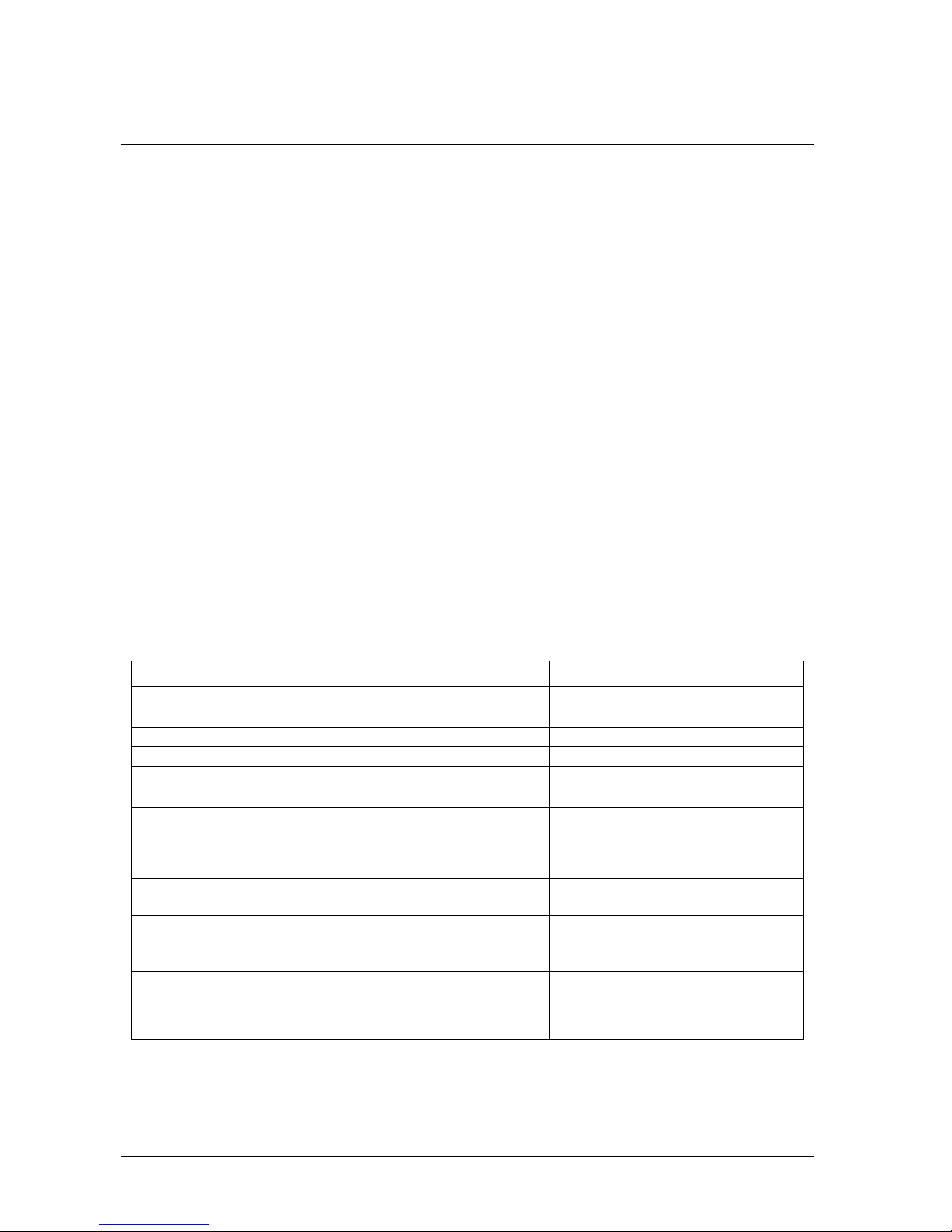
Comparing the 7080 and 7080D
Table 1-1 summarizes the features of the CB7080 and CB7080D modules.
Table 1-1. Comparison between CB-7080 and CB-7080D
5-digit LED display No Yes
Response to LED command No Yes
Module name programmable programmable
Counter preset value Yes (programmable) Yes (programmable)
Alarm on counter 0 only Yes (programmable) Yes (programmable)
Alarm on counter 0 and 1 Yes (programmable) Yes (programmable)
Channel 0 and channel 1 are both non-
isolated (input mode 0, $AAB0)
Channel 0 and channel 1 are both
isolated (input mode 1, $AAB1)
Channel 0 is non-isolated and channel
1 is isolated (input mode 2, $AAB2)
Channel 0 is isolated and channel 1 is
non-isolated(input mode 3, $AAB3)
Input frequency 100 kHz max. 100 kHz max.
Default setting 4080 compatible
CB-7080 CB-7080D
Yes Yes
Yes Yes
Yes Yes
Yes Yes
4080D compatible
High alarm on counter 0
and 1
Counter preset value: 0
High/High-High alarm on counter 0
Counter preset value: 0
1-1
Page 7

CB-7080 & CB-7080D Counter/Timer User's Guide Pin assignments
CB-7080D
Pin assignments
The pin names and locations on the CB-7080D module are shown in Figure 1-1.
Figure 1-1. CB-7080D pin identification
Specifications
CB-7080 Counter/Frequency Module
CB-7080D CB-7080 with LED Display
Counter Input Channels Two independent 32 bit counters, counter 0 and 1.
Input signal Isolated or non-isolated programmable
Isolation input levels:
Logic level 0 +1 V max
Logic level 1 +3.5 V to +30 V
Isolation voltage 3750 V RMS
Non-isolation input threshold level: Programmable
Logic level 0 0 to +5 V (default = 0.8 V)
Logic level 1 0 to +5 V (default = 2.4 V)
Maximum count 32 bit (4,294,967,295)
Programmable digital noise filter
Alarming alarm on counter 0 or counter 0 and 1, programmable
Counter preset value Programmable
Display LED Indicator 5-digit read out, channel 0 or channel 1
Frequency measurement
Input frequency 1 Hz to 100 kHz max
Programmable built-in gate time 1.0 or 0.1 sec
2 µs to 65 ms
1-2
Page 8

CB-7080 & CB-7080D Counter/Timer User's Guide Functional block diagram
Non-isolated inputs
Digital output
Capacity 2 channels, open-collector to 30 V, 30 mA max load
Power Dissipation 300 mW
Power
Power Requirements +10V to 30V (non-regulated)
Power consumption
CB-7080 2.0 W
CB-7080D 2.2 W
Functional block diagram
5V
5-digit LED (CB-7080D)
In0+
Alarm
Output
D+
D-
V+
V-
D/O
O.C.
RS-485
DC
DC
EEPROM
Embedded
Controller
Programmable Digital Filter
5V
0V
Isolated/Non-isolated input selection
Isolated/Non-isolated gate selection
Counter_1
Counter_0
In0-
5V
In1+
In1-
5V
Gate0+
Gate0-
Programmable threshold voltage
Figure 1-2. CB-7080D Block Diagram
1-3
5V
Gate1+
Gate1-
Isolated inputs
Gate0(TTL)
Gate1(TTL)
In0(TTL)
In1(TTL)
Page 9

CB-7080 & CB-7080D Counter/Timer User's Guide Application wiring
6 5 4 3 8 2
10
12 11
16 17 18 13 19 20
Application wiring
Output drive to SSR or other load
CB-7080 and CB-7080D
11 Gate1-
12
Gate1+
In1-
13
In1+
143
15-
Gate0-
Gate0+
16
In0-
17
In0+
18
Do0/Lo
19
Do1/Hi
20
GND
+VS
Data+
Data-
Init*
Gate1
In1
D.Gnd
Gate0
In0
10
9
8
7
6
5
4
3
2
1
Ext. GND
Ext. 24V
RS-485 Data-
RS-485 Data-
1N4001
External Power
External Load
R1
+VS
SSR AC
R2
Figure 1-3. Output drive to SSR or other load
Note:
If the external load is resistive, the 1N4001 can be omitted. (transistor, lamp, resistor, etc.).
If the external load is inductive, the 1N4001 cannot be omitted. (relay coil, etc.).
Frequency Input
Use the $AABS command to select the isolated/non-isolated input.
Frequency 1
(isolated)
Frequency 0
(isolated)
Gate1-
Gate1+
In1-
In1+
143
15-
Gate0-
Gate0+
In0-
In0+
Do0/Lo
Do1/Hi
CB-7080 & CB-7080D
Figure 1-4. Frequency input
GND
+VS
Data+
Data-
Init*
Gate1
In1
D.Gnd
Gate0
In0
Ext. GND
9
Ext. 24V
RS-485 Data+
7
RS-485 Data-
Frequency-1
(non- isolated)
Frequency-0
1
(non- isolated)
1-4
Page 10

CB-7080 & CB-7080D Counter/Timer User's Guide Application wiring
Counter input
Counter-1
Input 1 & Gate-1
(isolated)
Counter-0
Input 0 & Gate-0
(isolated)
11 Gate1-
12
Gate1+
In1-
13
In1+
143
15-
Gate0-
Gate0+
16
In0-
17
In0+
18
Do0/Lo
19
Do1/Hi
20
CB-7080 & CB-7080D
GND
+VS
Data+
Data-
Init*
Gate1
In1
D.Gnd
Gate0
In0
10
9
8
7
6
5
4
3
2
1
Ext. GND
Ext. 24V
RS-485 Data-
RS-485 Data-
Counter-1 & Gate-1
(non-isolated)
Counter-0 & Gate-0
(non-isolated)
Figure 1-5. Counter input
Frequency input measurement
Perform the following procedure to measure the frequency input of each channel. Refer to Figure 1-4 for the
wire connection.
1. Power on and run the test.exe application.
2. Press 2
3. Press $012[Enter] Receive=!01500600
4. Press 2
5. Press %0101510600[Enter] Receive=>!01
6. Press 2
7. Press $01B0[Enter] Receive=!01
8. Press 2
9. Press #010[Enter] Receive=>????????
10. Press 2
11. Press #011[Enter] Receive=>????????
In step 3: the status of CB-7080 is COUNTER mode.
In step 5: Change to frequency mode.
In step 7: Select non-isolated input.
In step 9: Frequency measurement of channel-0.
In step 11: Frequency measurement of channel-1.
Note
The command $01B1 can be used in step 7 to select the isolated inputs. The commands $01B2 and $01B3 are
used for the other input mode selections.
1-5
Page 11

CB-7080 & CB-7080D Counter/Timer User's Guide Default settings
Counter input measurement
Perform the following procedure to measure the counter input. Refer to Figure 1-5 for the wire connection.
1. Power on and run the
2. Press
3. Press
4. Press
5. Press
6. Press
7. Press
8. Press
9. Press
2
$012
[Enter] Receive=!01500600
2
$01B0
[Enter] Receive=!01
2
#010
[Enter] Receive=>????????
2
#011
[Enter] Receive=>????????
test.exe
application.
In step 3: The status of CB-7080 is COUNTER mode
In step 5: Select non-isolated input
In step 7: Counter measurement of channel-0
In step 9: Counter measurement of channel-1
Note:
The command $01B1 can be used in step 5 to select the isolated inputs. The commands $01B2 and $01B3 are
used for the other input mode selections.
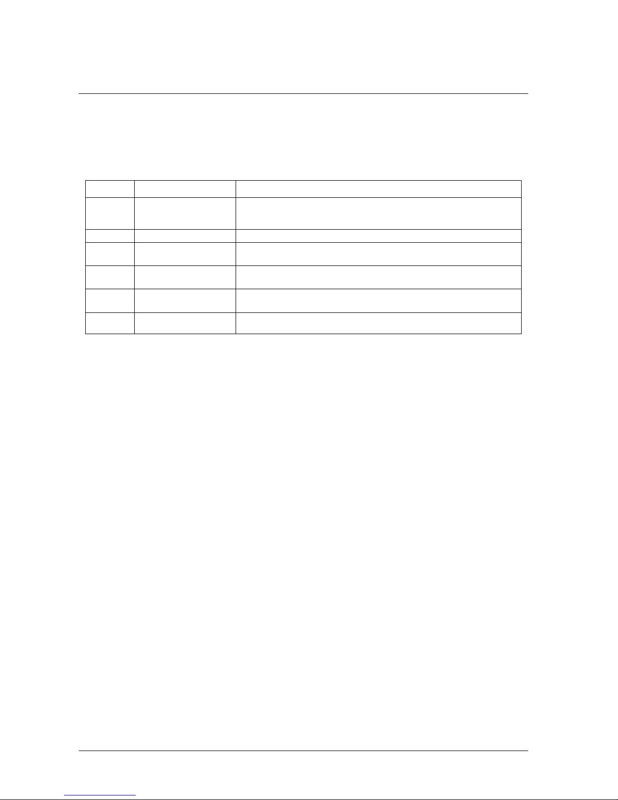
Default settings
CB-7080 and CB-7080D default settings are listed in Table 1-2.
Table 1-2. Default Settings
Address 01
Baud rate 9600
Checksum disabled
Data bits 1 start + 8 data + 1 stop (no parity)
Type 50 (counter input)
Alarm
CB-7080: High alarm on counter 0 and counter 1
CB-7080D High/High-High alarm on counter 0
Application notes
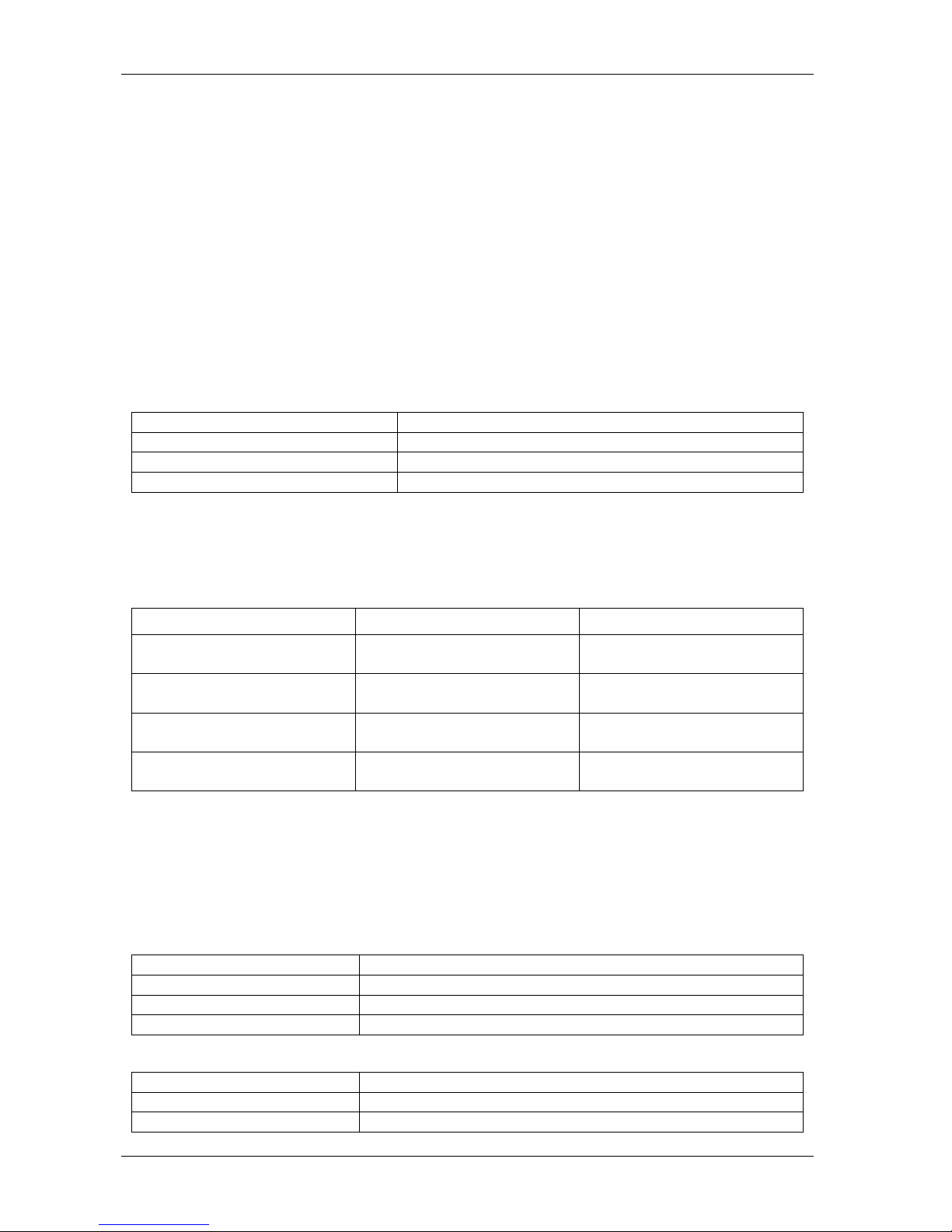
Counter/Frequency input mode selection
Select the counter/frequency input from either isolated or non-isolated signal inputs. Channel 0 and channel 1
can be selected separately. Four different input modes are listed in the following table. These four input
modes can be used in both the CB-7080 and the CB-7080D.
Table 1-3. Counter frequency input
Input Mode Command Channel 0 Channel 1
Input mode 0 $AAB0 Non-isolated Non-isolated
Input mode 1 $AAB1 Isolated Isolated
Input mode 2 $AAB2 Non-isolated Isolated
Input mode 3 $AAB3 Isolated Non-isolated
1-6
Page 12

CB-7080 & CB-7080D Counter/Timer User's Guide Application notes
Counter alarm mode selection
There are no alarm functions in frequency mode (51). There are two counter alarm modes,
Alarm Mode 1
. These two alarm modes can be used in both CB-7080 and CB-7080D.
Alarm Mode 0 is used for two-channel applications, as follows:
To select alarm mode 0: ~AAA0 (for both channels)
To enable channel 0: @AAEA0
To disable channel 0: @AADA0
Set the High alarm limit of channel 0: @AAPA(data)
if (counter 0 >= alarm limit 0) D/O 0 turn ON
if (counter 0 < alarm limit 0) D/O 0 turn OFF
Enable channel 1: @AAEA1
Disable channel 1: @AADA1
Set the High alarm limit of channel 1: @AASA(data)
if (counter 1 >= alarm limit 1) D/O 1 turn ON
if (counter 1 < alarm limit 1) D/O 1 turn OFF
Alarm mode 1 is used for single-channel applications, as follows:
Alarm Mode 0
and
Select alarm mode 1: ~AAA1 (for channel 0 only)
Enable channel 0: @AAEAT
Disable channel 0: @AADA
Clear latch alarm: @AACA
Set High alarm limit: @AAPA(data)
Set High-High alarm limit: @AASA(data)
Counter 0 < High alarm OFF OFF
High alarm <= counter 0, and
counter 0 < High-High alarm
High-High alarm <= counter 0 ON ON
Note:
ON OFF
The High-High alarm must greater than the High alarm.
Digital output application notes
The D/O0 and D/O1 can be used as D/O or an alarm output, as follows:
D/O in the frequency mode.
D/O in the counter mode and alarm disabled (by @AADA or @AADAN command).
An alarm output in the counter mode and an alarm enable (by @AAEAT or @AAEAN command).
1-7
Page 13

CB-7080 & CB-7080D Counter/Timer User's Guide Application notes
Table 1-4 Digital Alarm Configuration
Frequency mode D/O 0 D/O 1
Counter mode and alarm disabled D/O 0 D/O 1
Counter mode and alarm enable
(alarm mode 1, ~AAA1)
Counter mode and alarm enable (alarm
mode 0, ~AAA0 and @AAEA0)
Counter mode and alarm enable (alarm
mode 0, ~AAA0 and @AAEA1)
D/O 0 D/O 1
High alarm on counter 0 High-High alarm on counter 0
Alarm on counter 0 D/O 1 or alarm on counter 1
D/O 0 or alarm on counter 0 alarm on counter 1
Programmable threshold voltage setting
The programmable threshold voltage is valid for a non-isolated input of counter mode (50) and frequency
mode (51). The default settings are:
TTL compatible
Low trigger level = 0.8 volt
High trigger level = 2.4 volts
You can change the high trigger level by the $AA1H (data) command. The low trigger can be changed by the
$AA1L (data) command. The high trigger level must be greater than the low trigger level.
Digital filter setting
The digital filter is disabled in frequency mode (51). It is designed as a pulse-width filter for both high/low
pulses, and is valid for both non-isolated and isolated inputs. The digital filter can be enabled or disabled. Key
points of digital filter usage include:
1. Use $AABS to select the input signal.
2. Use $AA0H(data) to set the minimum width of high level.
3. Use $AA0L(data) to set the minimum width of low level.
4. Use $AA4S to enable/disable the digital filter (both channels).
If the high width of the input signal is smaller than the minimum high width of digital filter, the input signal is
filtered out. Also, the low width of the input signal must be greater than the minimum low width of digital
filter.
For example, if the width of the input signal is >1000 µs, set the digital filter at 900 µs. Therefore, all noise
<900 µs is filtered out by the digital filter. These steps are given as follows:
$AAB0
$AA0H00900
$AA0L00900
$AA41
1-8
Page 14
CB-7080 & CB-7080D Counter/Timer User's Guide Application notes
Gate control setting
The gate control is ignored in frequency mode (51). The gate control is disabled in counter mode (50) by
default. Use the following commands to enable/disable the gate control:
When you use the $AAA0 command, the gate input must be low to enable the counter.
When you use the $AAA1 command, the gate input must be high to enable the counter.
When you use the $AAA2 command, the gate input is disabled. The counter is
always enabled.
Preset value setting
The preset value is ignored in frequency mode (51). The counters go to their preset value in the first power-on
state. The reset counter command, $AA6N, also forces the counters to go to their preset value. The default
preset value is 0. Use the $AAPN(data) command to change the preset value. The key points include:
Table 1-5: Preset values
Factory default setting Counter preset value is 0
Power on state Counters 0/1 are set to the preset value
$AA6N Counter N is set to the preset value
$AAPN(data) Sets the preset value of counter N
Frequency input applications
To set the module to frequency mode set the configuration code to 51in the Set module configuration
command.
Table 1-6. Frequency mode settings
Command Result - Frequency 0 Result - Frequency 1
$AAB0 to set input mode 0
$AA1H(data) and $AA1L(data)
$AAB1 to set input mode 1
$AAB2 to set input mode 2
$AA1H(data) & $AA1L(data)
$AAB3 to set input mode 3
$AA1H(data) & $AA1L(data)
To measure frequency:
1. Use the $AA1H(data) and $AA1L(data) commands to set the threshold voltage values, if the frequency
input is a non-isolated input.
2. Use the $AAB? command to select the mode (this command will clear the current frequency first).
3. Use the #AA? command to perform frequency measurement.
Only four commands are important in frequency measurement mode:
$AAB? Select mode
$AA1H(data) Set high-level threshold value
$AA1L(data) Set low-level threshold value
#AA? Perform frequency measurement
Non-isolated channel 0 and
threshold voltage values active
Isolated channel 0 Isolated channel 1
Non-isolated channel 0 and
threshold voltage values active
Isolated channel 0 Non-isolated channel 1 and
Non-isolated channel 1 and
threshold voltage values active
Isolated channel 1
threshold voltage values active
The status-read-back commands are:
$AAB? Mode read back
$AA1H High_level threshold value read back
$AA1L(data) Low_level threshold value read back
1-9
Page 15

CB-7080 & CB-7080D Counter/Timer User's Guide Application notes
Counter input applications
To set the module to frequency mode set the configuration code to 50 in the Set module configuration
command
Table 1-7. Counter mode settings
$AAB0 to set input mode 0
$AA1H(data) and $AA1L(data)
$AAB1 to set input mode 1
$AAB2 to set input mode 2
$AA1H(data) and $AA1L(data)
$AAB3 to set input mode 3
$AA1H(data) and $AA1L(data)
Note:
Counter 0 Counter 1
Non-isolated channel 0 and
threshold voltage values active
Isolated channel 0 Isolated channel 1
Non-isolated channel 0 and
threshold voltage values active
Isolated channel 0 Non-isolated channel 1 and
Non-isolated channel 1 and
threshold voltage values active
Isolated channel 1
threshold voltage values active
The threshold voltage value commands $AA1H(data) and $AA1L(data) are effective for non-isolated inputs
only.
Configuration Codes
Use the configuration codes listed in the following tables to set or read back the baud rate, the status , and the
input type configuration codes of a module.
Table 1-8. Baud Rate Configuration Code: CC
CC Baud Rate
03 1200 BPS
04 2400 BPS
05 4800 BPS
06 9600 BPS
07 19200 BPS
08 38400 BPS
09 57600 BPS
0A 115200 BPS
Table 1-9. Status Configuration Code: FF, 2-char (for all)
7 6 5 4 3 2 1 0
0 checksum
0=disabled
1=enabled
TT Input Range
50 Counter
51 Frequency
0 0 0 frequency gate time
0: 0.1 second
1: 1.0 second
Table 1-10. Input Type Configuration Code: TT
0 0
1-10
Page 16
Command Set
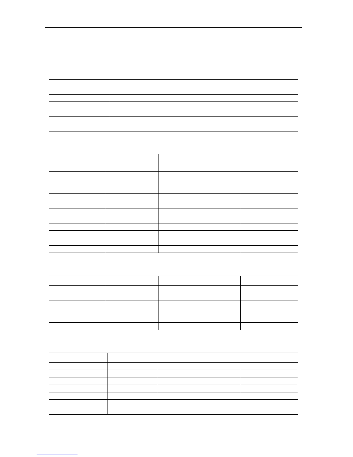
Overview
The commands in this section are grouped by function, and summarized as listed below.
Table Function Description
Table 2-1 General Command s
Table 2-2 Frequency Command s
Table 2-3 General Counter
Commands
Table 2-4 Alarm Mode 0
Commands
Table 2-5 Alarm Mode 1
Commands
Table 2-6 LED Commands
Read a module's name, status, firmware number and init pin
Read/write a module's configuration
Read or enable the watchdog timer
Set or read the input mode and trigger levels of a module
Set or read counter input settings of a module
Used in two-channel applications to set a different alarm mode for
each channel.
Used in two-channel application to set the same alarm mode for each
channel.
Get or set LED configuration
To send data to the LED
2
General syntax format
Commands are constructed with individual pieces of information represented as code. Each command is
structured as follows:
One-character Delimiter that indicates the type of command to execute.
Two-character HEX module address, from 00 to FF
Function, which indicates the task to execute.
Terminator character, to indicate the end of the command.
This section lists the commands to use to perform specific functions. When writing a command, replace the
generic address with the address of the module you want to perform the task on. For example, to read the
name of module 1:
Select $AAM, the command used to read the name of a module (see page 35).
1. Replace the address (AA) with 01, to indicate module 1.
2. Terminate the command with a carriage return (cr).
This command would then be written as $01M(cr).
2-1
Page 17
CB-7080 & CB-7080D Counter/Timer User's Guide General syntax format
Delimiter characters
The characters %, #, ~, %, $, @ are used as the leading character in a command. These characters indicate the
type of command to execute.
Delimiter Character Usage
% Set the configuration of a module.
#
~ Reset the data.
$ Get/set (read/write) module information.
[ ] Characters inside [ ] indicate optional code characters, such as [chk]
(cr) Indicates the end of the command.
! Always the leading character in the response to a command.
General Commands
Table 2-1. General Command Set
Command Response Description Reference
%AANNTTCCFF !AA Set the module configuration Page 2-4
#AAN >(data) Read the counter or frequency Page 2-1
~** No Response Host OK Page 2-2
~AA0 !AASS Read the module status Page 2-3
~AA1 !AA Reset the module status Page 2-4
~AA2 !AATT Read the Host Watchdog Timer Page 2-5
~AA3ETT !AA Enable the Host Watchdog Timer Page 2-6
~AAO(name) !AA Set the module name Page 2-8
$AA2 !AATTCCFF Read the module configuration Page 2-17
$AAF !AA(data) Read the firmware number Page 2-33
$AAI !AAS Read the value of INIT* pin Page 2-34
$AAM !AA(data) Read the module name Page 2-35
Frequency commands
Table 2-2. Frequency Command Set
Command Response Description Reference
$AAB !AAS Read the input mode Page 2-31
$AABS !AA Set the input mode Page 2-32
$AA1H !AA(data) Read the high trigger level Page 2-13
$AA1H(data) !AA Set the high trigger level Page 2-14
$AA1L !AA(data) Read the low trigger level Page 2-15
$AA1L(data) !AA Set the low trigger level Page 2-16
General counter commands
Table 2-3. General Counter Command Set
Command Response Description Reference
~AAAS !AA Set the counter alarm mode Page 2-7
$AA0H !AA(data) Read the minimum width of High Page 2-9
$AA0H(data) !AA Set the minimum width of High Page 2-10
$AA0L !AA(data) Read the minimum width of Low Page 2-11
$AA0L(data) !AA Set the minimum width of Low Page 2-16
$AA1H !AA(data) Read the high trigger level Page 2-13
$AA1H(data) !AA Set the high trigger level Page 2-14
2-2
Page 18

CB-7080 & CB-7080D Counter/Timer User's Guide General syntax format
Command Response Description Reference
$AA1L !AA(data) Read the low trigger level Page 2-15
$AA1L(data) !AA Set the low trigger level Page 2-16
$AA3N !AA(data) Read the max. counter value Page 2-18
$AA3N(data) !AA Set the max. counter value Page 2-19
$AA4 !AAS Read the filter status Page 2-20
$AA4S !AA Set the filter status Page 2-21
$AA5N !AAS Read the counter status Page 2-22
$AA5NS !AA Set the counter status Page 2-23
$AA6N !AA Reset the counter Page 2-24
$AA7N !AAS Read the overflow status Page 2-25
$AAA !AAG Read the gate control mode Page 2-29
$AAAG !AA Set the gate control mode Page 2-30
$AAB !AAS Read the input mode Page 2-31
$AABS !AA Set the input mode Page 2-32
@AADI !AAS0D00 Read the D/O and alarm state Page 2-36
@AADO0D !AA Set the D/O value Page 2-38
@AAGN !AA(data) Read the preset value Page 2-44
@AAPN(data) !AA Set the preset value Page 2-45
Alarm mode 0 commands
Table 2-4. Alarm-mode 0 Command Set
Command Response Description Reference
@AAEAN !AA Enable the alarm Page 2-39
@AADAN !AA Disable the alarm Page 2-43
@AAPA(data) !AA Set the counter 0 alarm value Page 2-46
@AASA(data) !AA Set the counter 1 alarm value Page 2-48
@AARP !AA Read the counter 0 alarm value Page 2-50
@AARA !AA Read the counter 0 alarm value Page 2-52
Alarm mode 1 commands
Table 2-5. Alarm-mode 1 Command Set
Command Response Description Reference
@AAEAT !AA Enable the alarm Page 2-40
@AACA !AA Clear the latch alarm Page 2-41
@AADA !AA Disable the alarm Page 2-42
@AAPA(data) !AA Set the Hi-alarm value Page 2-46
@AASA(data) !AA Set the Hi-Hi-alarm value Page 2-48
@AARP !AA Read the Hi-alarm value Page 2-51
@AARA !AA Read the Hi-Hi-alarm value Page 2-53
LED commands
Command Response Description Reference
$AA8 !AAS Read LED configuration Page 2-26
$AA8V !AA Set LED configuration Page 2-27
$AA9(data) !AA Send data to LED Page 2-28
Table 2-6. LED Command Set
2-3
Page 19

CB-7080 & CB-7080D Counter/Timer User's Guide %AANNTTCCFF
%AANNTTCCFF
Description
Syntax
: Set the configuration of a module.
: %AANNTTCCFF[chk](cr)
% A delimiter character.
AA Current 2-character HEX module address, from 00 to FF
NN New 2-character HEX module address, from 00 to FF
TT Input type code, refer to Table 1-10.
CC Baud rate code, refer to Table 1-8.
FF Status code, refer to Table 1-9.
[chk] 2-character checksum. If checksum is disabled, no [chk]
(cr) 0x0D
Response:
Valid response: !AA[chk](cr)
Invalid response: ?AA[chk](cr)
No response Syntax error, communication error or address error.
! A delimiter character indicating a valid response
? A delimiter character indicating an invalid response
AA 2-character HEX module address
[chk] 2-character checksum. If checksum is disabled, no [chk]
(cr) 0x0D
Examples
:
The address of module 01 is configured to a new address 02, counter mode:
command: %0102500600(cr)
response: !02(cr)
Change to frequency mode:
command: %0202510600(cr)
response: !02(cr)
2-4
Page 20

CB-7080 & CB-7080D Counter/Timer User's Guide #AAN
#AAN
Description:
Syntax
Read the counter or frequency value.
: #AAN[chk](cr)
# A delimiter character
AA 2-character HEX module address, from 00 to FF
N=0 Read Channel-0 counter or frequency value
N=1 Read Channel-1 counter or frequency value
[chk] 2-character checksum. If checksum is disabled, no [chk]
(cr) 0x0D
Response
:
Valid response [chk](data)(cr)
invalid response No Response
no response Syntax error, communication error or address error.
> A delimiter character indicating a valid response
(data) 8-character data (in HEX format)
[chk] 2-character checksum. If checksum is disabled, no [chk]
(cr)=0x0D
Examples:
Counter − 0=0x1E=30 (in decimal):
command: $012(cr)
response: !01500600(cr)
command: #010(cr)
response: >0000001E(cr)
Frequency − 1=0x1E Hz = 30 Hz (in decimal):
command: $022(cr)
response: !02510600(cr)
command: #021(cr)
response: >0000001E(cr)
2-1
Page 21

CB-7080 & CB-7080D Counter/Timer User's Guide ~**
~**
Description:
Syntax:
The host sends this command to tell all modules “Host is OK”.
~**[chk](cr)
~ A delimiter character
[chk] 2-character checksum. If checksum is disabled, no [chk]
(cr) 0x0D
Response
:
No response
Examples
:
command ~**(cr)
response No Response
2-2
Page 22

CB-7080 & CB-7080D Counter/Timer User's Guide ~AA0
~AA0
Description:
Reads the module status. The module status will be latched until ~AA1 command is sent. If the
host watchdog is enabled and the host is down, (no ~** command received), the module status will be set to 4.
If the module status=4, all output commands are ignored.
Syntax:
~AA0[chk](cr)
~ A delimiter character
AA 2-character HEX module address, from 00 to FF
[chk] 2-character checksum. If checksum is disabled, no [chk]
(cr) 0x0D
Response
:
Valid response !AASS[chk](cr)
Invalid response ?AA[chk](cr)
No response Syntax error, communication error or address error
! A delimiter character indicating a valid response
? A delimiter character indicating an invalid response
AA 2-character HEX module address
SS 2-character HEX status value:
Bit_0, Bit_1 = reserved
Bit_2 = 0: OK,
1: host watchdog time-out
[chk] 2-character checksum. If checksum is disabled, no [chk]
(cr) 0x0D
Examples
:
Status of module 01 is OK:
Command: ~010(cr)
Response: 0100(cr)
Module status=04; host watchdog timed-out; HOST is down now:
Command: ~020(cr)
Response: 0204(cr)
2-3
Page 23

CB-7080 & CB-7080D Counter/Timer User's Guide ~AA1
~AA1
Description:
Resets the module status. The module status will be latched until ~AA1 command is sent. If the
module status=4, all output commands will be ignored. Read the module status first to verify that the module
status is 0. If the module status is not 0, only a ~AA1 command can clear the module status.
Syntax
: ~AA1[chk](cr)
~ A delimiter character
AA 2-character HEX module address, from 00 to FF
[chk] 2-character checksum If checksum is disabled, no [chk]
(cr) 0x0D
Response
:
Valid response !AA[chk](cr)
invalid response ?AA[chk](cr)
No response: Syntax error, communication error or address error
! A delimiter character indicating a valid response
? A delimiter character indicating an invalid response
AA 2-character HEX module address
[chk] 2-character checksum. If checksum is disabled, no [chk]
(cr) 0x0D
Examples
:
Module status=0x04 host is down:
command: ~010(cr)
response: !0104(cr)
Output command is ignored:
command: @01DO00(cr )
response: !(cr)
Clear module status:
command: ~011(cr)
response: !01(cr)
Module status=0x00:
command: ~010(cr)
response: !0100(cr)
Output command is OK:
command: @01DO00(cr)
response: >(cr )
2-4
Page 24

CB-7080 & CB-7080D Counter/Timer User's Guide ~AA2
~AA2
Description:
Reads the status and timer value of host watchdog. When the host watchdog is enabled, the host
must send ~** command to all modules before the timer times-out. When the ~** command is received, the
host watchdog timer is reset and starts counting down. Use ~AA3ETT to enable/disable/setting the host
watchdog timer.
Syntax:
~AA2[chk](cr)
~ A delimiter character
AA 2-character HEX module address, from 00 to FF
[chk] 2-character checksum. If checksum is disabled, no [chk]
(cr) 0x0D
Response
:
Valid response AASTT[chk](cr)
invalid response ?AA[chk](cr)
no response Syntax error, communication error or address error
! A delimiter character indicating a valid response
? A delimiter character indicating an invalid response
AA 2-character HEX module address
S=0 Host watchdog is disabled
S=1 Host watchdog is enabled
TT 2-character HEX value, from 00 to FF, unit=0.1 second
[chk] 2-character checksum. If checksum is disabled, no [chk].
(cr) 0x0D
Examples
:
Host watchdog timer of module 01 is disabled
command: ~012(cr)
response: !01000(cr)
Host watchdog timer of module 02 is enabled and time-out
time = 0.1 x 10 = 1 second
command: ~022(cr)
response: !0210A(cr)
2-5
Page 25

CB-7080 & CB-7080D Counter/Timer User's Guide ~AA3ETT
~AA3ETT
Description:
Enable/disable the timer value of host watchdog. The host watchdog timer is a software host
watchdog. When the software host watchdog is enabled, the host must send ~** command to all modules
before the timer times-out. When the ~** command is received, the host watchdog timer is reset and restarted.
Use ~AA2 to read the host watchdog status and value.
Syntax
: ~AA3ETT[chk](cr)
~ A delimiter character
AA 2-character HEX module address, from 00 to FF
E 0 is disabled and 1 is enabled
TT 2-character HEX value, from 00 to FF, unit=0.1 second
[chk] 2-character checksum. If checksum is disabled, no [chk].
(cr) 0x0D
Response
:
Valid response !AA[chk](cr)
Invalid response ?AA[chk](cr)
no response Syntax error, communication error or address error
! A delimiter character indicating a valid response
? A delimiter character indicating an invalid response
AA 2-character HEX module address
[chk] 2-character checksum. If checksum is disabled no [chk]
(cr) 0x0D
Examples
:
Disable host watchdog timer of module 01
command ~013000(cr)
response !01(cr)
Host watchdog timer of module 02 is enabled and time-out time = 0.1 x 10 = 1 second.
command ~02310A(cr)
response !02(cr)
2-6
Page 26

CB-7080 & CB-7080D Counter/Timer User's Guide ~AAAS
~AAAS
Description
: Sets counter alarm mode. Refer to "Counter alarm mode selection" on page 1-7 for more
information.
Syntax
: ~AAAS[chk](cr)
~ A delimiter character
AA 2-character HEX module address, from 00 to FF
S=0 alarm mode 0.
S=1 alarm mode 1.
[chk] 2-character checksum. If checksum is disabled no [chk]
(cr) 0x0D
Response
:
Valid response !AA[chk](cr)
invalid response ?AA[chk](cr)
no response Syntax error, communication error or address error
! A delimiter character indicating a valid response
? A delimiter character indicating an invalid response
AA 2-character HEX module address
[chk] 2-character checksum. If checksum is disabled, no [chk].
(cr) 0x0D
Examples
:
Set alarm mode=0.
command: ~01A0(cr)
response: !01(cr)
Set alarm mode=1.
command: ~02A1(cr)
response: !02(cr)
2-7
Page 27

CB-7080 & CB-7080D Counter/Timer User's Guide ~AAO(name)
~AAO(name)
Description
Syntax
: Sets the module name.
: ~AAO(name)[chk](cr)
~ A delimiter character
AA 2-character HEX module address, from 00 to FF
(name) 4-character/5-character module name
[chk] 2-character checksum. If checksum is disabled, no [chk]
(cr) 0x0D
Response
:
Valid response !AA[chk](cr)
invalid response ?AA[chk](cr)
No response Syntax error, communication error or address error
! A delimiter character indicating a valid response
? A delimiter character indicating an invalid response
AA 2-character HEX module address
[chk] 2-character checksum. If checksum is disabled, no [chk].
(cr) 0x0D
Examples
:
Change module name from 7080 to 8080
command: $01M(cr)
response: !017080(cr)
command: ~01O8080(cr)
response: !01(cr)
Change module name from 7080D to 8080D
command: $01M(cr)
response: !017080D(cr)
command: ~01O8080D(cr)
response: !01(cr)
Note
This command was designed for OEM/ODM users. You can use it to change the module name for other
purposes.
2-8
Page 28

CB-7080 & CB-7080D Counter/Timer User's Guide $AA0H
$AA0H
Description:
Reads the minimum input signal width at high level. Refer to "Digital filter setting" on page 1-8
for more information.
Syntax:
$AA0H[chk](cr)
$ A delimiter character
AA 2-character HEX module address, from 00 to FF
[chk] 2-character checksum. If checksum is disabled, no [chk].
(cr) 0x0D
Response
:
Valid response !AA(data)[chk](cr)
Invalid response ?AA[chk](cr)
No response Syntax error, communication error or address error
! A delimiter character indicating a valid response
? A delimiter character indicating an invalid response
AA 2-character HEX module address
(data)
5-character decimal value for min. width at high level. The unit is microseconds
(µs) and the range can be from 2 µs to 65535 µs.
[chk] 2-character checksum. If checksum is disabled, no [chk].
(cr) 0x0D
Examples
:
Min. width = 10 µs
command $010H(cr)
response !0100010(cr)
Min. width = 1000 µs = 1 ms
command $020H(cr)
response !0201000(cr)
2-9
Page 29

CB-7080 & CB-7080D Counter/Timer User's Guide $AA0H(data)
$AA0H(data)
Description
: Sets the minimum input signal width at high level. Refer to "Digital filter setting" on page 1-8
for more information.
Syntax
: $AA0H(data)[chk](cr)
$ A delimiter character
AA 2-character HEX module address, from 00 to FF
(data)
5-character decimal value for minimum width at high level. The unit is
microseconds (µs) and the range can be from 2 µs to 65535 µs.
[chk] 2-character checksum. If checksum is disabled, no [chk].
(cr) 0x0D
Response
:
Valid response !AA[chk](cr)
invalid response ?AA[chk](cr)
No response Syntax error, communication error or address error
! A delimiter character indicating a valid response
? A delimiter character indicating an invalid response
AA 2-character HEX module address
[chk] 2-character checksum. If checksum is disabled, no [chk]
(cr) 0x0D
Examples
:
Min. width = 10 µs
command: $010H00010(cr)
response: !01(cr)
Min. width = 1000 µs = 1 ms
command: $020H01000(cr)
response: !02(cr)
2-10
Page 30

CB-7080 & CB-7080D Counter/Timer User's Guide $AA0L
$AA0L
Description
: Read the minimum input signal width at low level. Refer to "Digital filter setting" for more
information.
Syntax
: $AA0L[chk](cr)
$ A delimiter character
AA 2-character HEX module address, from 00 to FF
[chk] 2-character checksum. If checksum is disabled, no [chk].
(cr) 0x0D
Response
:
Valid response !AA(data)[chk](cr)
invalid response ?AA[chk](cr)
no response Syntax error, communication error or address error
! A delimiter character indicating a valid response
? A delimiter character indicating an invalid response
AA 2-character HEX module address
(data)
5-character decimal value for min. width at low level. The unit is microseconds and
the range can be from 2 µs to 65535 µs.
[chk] 2-character checksum. If checksum is disabled, no [chk].
(cr) 0x0D
Examples
:
Min. width=20 µs
command: $010H(cr)
response: !0100020(cr)
Min. width=2000 µs
= 2 ms
command: $020H(cr)
response: !0202000(cr)
2-11
Page 31

CB-7080 & CB-7080D Counter/Timer User's Guide $AA0L(data)
$AA0L(data)
Description
: Sets the minimum input signal width at low level. Refer to "Digital filter setting" for more
information.
Syntax
: $AA0H(data)[chk](cr)
$ A delimiter character
AA 2-character HEX module address, from 00 to FF
(data) 5-character decimal value for min. width at low level. The unit is microseconds
(µs), and the range can be from 2 µs to 65535 µs.
[chk] 2-character checksum. If checksum is disabled, no [chk].
(cr) 0x0D
Response
:
Valid response !AA[chk](cr)
invalid response ?AA[chk](cr)
no response Syntax error, communication error or address error
! A delimiter character indicating a valid response
? A delimiter character indicating an invalid response
AA 2-character HEX module address
[chk] 2-character checksum. If checksum is disabled, no [chk].
(cr) 0x0D
Examples
:
Min. width = 20 µs
command: $010H00020(cr)
response: !01(cr)
Min. width = 2000 µs = 2 ms
command: $020H02000(cr)
response: !02(cr)
2-12
Page 32

CB-7080 & CB-7080D Counter/Timer User's Guide $AA1H
$AA1H
Description
: Reads the high trigger level of non-isolated input. Refer to "Programmable threshold voltage
setting" on page 1-8 for more information.
Syntax
: $AA1H[chk](cr)
$ A delimiter character
AA 2-character HEX module address, from 00 to FF
[chk 2-character checksum. If checksum is disabled, no [chk].
(cr) 0x0D
Response
:
Valid response !AA(data)[chk](cr)
Invalid response ?AA[chk](cr)
no response Syntax error, communication error or address error
! A delimiter character indicating a valid response
? A delimiter character indicating an invalid response
AA 2-character HEX module address
(data) 2-character decimal value for high trigger level. The unit is 0.1 volt and the range
can be from 0.0 to 5.0 volts.
[chk] 2-character checksum. If checksum is disabled, no [chk].
(cr) 0x0D
Examples
:
High trigger level=2.4 volts:
command:$011H(cr)
response: !0124(cr)
High trigger level=3.0 volts:
command: $021H(cr)
response:!0230(cr)
2-13
Page 33

CB-7080 & CB-7080D Counter/Timer User's Guide $AA1H(data)
$AA1H(data)
Description
: Sets the high trigger level of non-isolated inputs. Refer to "Programmable threshold voltage
setting" for more information.
Syntax
: $AA1H(data)[chk](cr)
$ A delimiter character
AA 2-character HEX module address, from 00 to FF
(data) 2-character decimal value for high trigger level. The unit is 0.1 volt, and the range
can be from 0.0 to 5.0V.
[chk] 2-character checksum. If checksum is disabled, no [chk].
(cr) 0x0D
Response
:
Valid response !AA[chk](cr)
Invalid response ?AA[chk](cr)
no response Syntax error, communication error or address error
! A delimiter character indicating a valid response
? A delimiter character indicating an invalid response
AA 2-character HEX module address
[chk] 2-character checksum,
if checksum is disabled no [chk]
(cr) 0x0D
Examples
:
High trigger level=2.4 volts
command: $011H24(cr)
response: !01(cr)
High trigger level=3.0 volts
command: $021H30(cr)
response: !02(cr)
Note:
The default value for the high trigger level is 2.4V
2-14
Page 34

CB-7080 & CB-7080D Counter/Timer User's Guide $AA1L
$AA1L
Description
: Read the Low trigger level of non-isolated input. Refer to "Programmable threshold voltage
setting" for more information.
Syntax
: $AA1L[chk](cr)
$ A delimiter character
AA 2-character HEX module address, from 00 to FF
[chk] 2-character checksum
if checksum is disabled no [chk]
(cr) 0x0D
Response
:
Valid response !AA(data)[chk](cr)
Invalid response ?AA[chk](cr)
No response Syntax error, communication error or address error
! A delimiter character indicating a valid response
? A delimiter character indicating an invalid response
AA 2-character HEX module address
(data) 2-character decimal value for low trigger level. The unit is 0.1V, and the range can
be from 0.0 to 5.0V.
[chk] 2-character checksum. If checksum is disabled, no [chk].
(cr) 0x0D
Examples
:
Low trigger level=0.8 volts:
command: $011L(cr)
response: !0108(cr)
Low trigger level=1.0 volts:
command: $021L(cr)
response: !0210(cr)
2-15
Page 35

CB-7080 & CB-7080D Counter/Timer User's Guide $AA1L(data)
$AA1L(data)
Description
: Set the low trigger level of non-isolated input. Refer to "Programmable threshold voltage
setting" for more information.
Syntax
: $AA1L(data)[chk](cr)
$ A delimiter character
AA 2-character HEX module address, from 00 to FF
(data) 2-character decimal value for low trigger level. The unit is 0.1V and the
range can be from 0.0 to 5.0V
[chk] 2-character checksum. If checksum is disabled, no [chk].
(cr) 0x0D
Response
Valid response !AA[chk](cr)
Invalid response ?AA[chk](cr)
no response Syntax error, communication error or address error
! A delimiter character indicating a valid response
? A delimiter character indicating an invalid response
AA 2-character HEX module address
[chk] 2-character checksum. If checksum is disabled, no [chk].
:
(cr) 0x0D
Examples
:
Low trigger level=0.8 volt:
command: $011L08(cr)
response: !01(cr)
Low trigger level=1.0 volt:
command: $021L10(cr)
response: !02(cr)
Note:
The default value for the low trigger level is 0.8V.
2-16
Page 36

CB-7080 & CB-7080D Counter/Timer User's Guide $AA2
$AA2
Description:
Syntax
Read the configuration of module.
: $AA2[chk](cr)
$ A delimiter character
AA 2-character HEX module address, from 00 to FF
[chk] 2-character checksum. If checksum is disabled, no [chk].
(cr) 0x0D
Response
:
Valid response: !AATTCCFF[chk](cr),
Invalid response: ?AA[chk](cr)
no response: Syntax error, communication error or address error
! A delimiter character indicating a valid response
? A delimiter character indicating an invalid response
AA 2-character HEX module address
TT Refer to Table 1-10.
CC Refer to Table 1-8.
FF Refer to Table 1-9.
[chk] 2-character checksum. If checksum is disabled, no [chk].
(cr) 0x0D
Examples
:
Address=01, counter, 9600 BPS, checksum disabled:
command: $012(cr)
response: !01500600(cr)
Address=02, frequency, 19200 BPS, checksum disabled:
command: $022(cr)
response: !02510700(cr)
Note
If you use the %AANNTTCCFF command to change module configuration, the new configuration code is
stored into EEPROM immediately.
The configuration code includes the module address, module type, baud rate code, checksum enable/disable
code, calibration code, power-on value and safe value.
The EEPROM data of a CB-7080 can be read an infinite number of times, and can be written about 100,000
times maximum. Therefore, you should not frequently change the configuration code for testing.
The $AA2 command is used to read EEPROM data only. You can send this command to CB-7080 module
without limit.
2-17
Page 37

CB-7080 & CB-7080D Counter/Timer User's Guide $AA3N
$AA3N
Description
Syntax
: Read the maximum counter value.
: $AA3N[chk](cr)
$ A delimiter character
AA 2-character HEX module address, from 00 to FF
N=0 channel-0 of counter or frequency
N=1 channel-1 of counter or frequency
[chk] 2-character checksum. If checksum is disabled, no [chk].
(cr) 0x0D
Response
:
Valid response !AA(data)[chk](cr)
Invalid response ?AA[chk](cr)
no response Syntax error, communication error or address error
! A delimiter character indicating a valid response
? A delimiter character indicating an invalid response
AA 2-character HEX module address
(data) 8-character HEX value.
[chk] 2-character checksum. If checksum is disabled, no [chk].
(cr) 0x0D
Examples
:
Counter-0 from preset value to FFFFh
command: $0130(cr)
response: !010000FFFF(cr)
Counter-1 from preset value to FFFFFFFFh
command: $0131(cr)
response: !01FFFFFFFF(cr)
2-18
Page 38

CB-7080 & CB-7080D Counter/Timer User's Guide $AA3N(data)
$AA3N(data)
Description
Syntax
: Set the maximum counter value.
: $AA3N(data)[chk](cr)
$ A delimiter character
AA 2-character HEX module address, from 00 to FF
N=0 channel-0 of counter or frequency
N=1 channel-1 of counter or frequency
(data) 8-character HEX value.
[chk] 2-character checksum. If checksum is disabled, no [chk]
(cr) 0x0D
Response
:
Valid response !AA(data)[chk](cr)
Invalid response ?AA[chk](cr)
no response syntax error, communication error or address error
! A delimiter character indicating a valid response
? A delimiter character indicating an invalid response
AA 2-character HEX module address
[chk] 2-character checksum. If checksum is disabled, no [chk]
(cr) 0x0D
Examples
:
Counter-0 from preset value to FFFFh:
command: $01300000FFFF(cr)
response: !01(cr)
Counter-1 from preset value to FFFFFFFFh:
command: $0131FFFFFFFF(cr)
response: !01(cr)
2-19
Page 39

CB-7080 & CB-7080D Counter/Timer User's Guide $AA4
$AA4
Description
Syntax
: Read the status of digital filter. Refer to "Digital filter setting" for more information.
: $AA4[chk](cr)
$ A delimiter character
AA 2-character HEX module address, from 00 to FF
[chk] 2-character checksum. If checksum is disabled, no [chk]
(cr) 0x0D
Response
:
Valid response !AAS[chk](cr)
Invalid response ?AA[chk](cr)
no response Syntax error, communication error or address error
! A delimiter character indicating a valid response
? A delimiter character indicating an invalid response
AA 2-character HEX module address
S=0 digital filter is disabled
S= 1 digital filter is enable
[chk] 2-character checksum. If checksum is disabled, no [chk]
(cr) 0x0D
Examples
:
Digital filter is disabled:
command: $014(cr)
response: !010(cr)
Digital filter is enabled:
command: $024(cr)
response: !021(cr)
2-20
Page 40

CB-7080 & CB-7080D Counter/Timer User's Guide $AA4S
$AA4S
Description:
Syntax:
Set the filter status. Refer to "Digital filter setting" for more information.
$AA4S[chk](cr)
$ A delimiter character
AA 2-character HEX module address, from 00 to FF
S=0 digital filter is disabled
S=1 digital filter is enabled
[chk] 2-character checksum. If checksum is disabled, no [chk]
(cr) 0x0D
Response
:
Valid response !AA[chk](cr)
Invalid response ?AA[chk](cr)
no response Syntax error, communication error or address error
! A delimiter character indicating a valid response
? A delimiter character indicating an invalid response
AA 2-character HEX module address
[chk] 2-character checksum. If checksum is disabled, no [chk]
(cr) 0x0D
Examples
:
Disable the digital filter:
command: $0140(cr)
response !01(cr)
Enable the digital filter:
command $0241(cr)
response !02(cr)
2-21
Page 41

CB-7080 & CB-7080D Counter/Timer User's Guide $AA5N
$AA5N
Description
Syntax
: Read the counter status
: $AA5N[chk](cr)
$ A delimiter character
AA 2-character HEX module address, from 00 to FF
N=0 counter 0
N=1 counter 1
[chk] 2-character checksum. If checksum is disabled, no [chk]
(cr) 0x0D
Response
:
Valid response !AAS[chk](cr)
Invalid response ?AA[chk](cr)
no response Syntax error, communication error or address error
! A delimiter character indicating a valid response
? A delimiter character indicating an invalid response
AA 2-character HEX module address
S=0 counter is stopped (is disabled)
S= 1 counter is started (enabled)
[chk] 2-character checksum. If checksum is disabled, no [chk]
(cr) 0x0D
Examples
:
Stop Counter 0:
command $0150(cr)
response !010(cr)
Start Counter 1:
command $0151(cr)
response !011(cr)
2-22
Page 42

CB-7080 & CB-7080D Counter/Timer User's Guide $AA5NS
$AA5NS
Description
Syntax
: Set the counter status
: $AA5NS[chk](cr)
$ A delimiter character
AA 2-character HEX module address, from 00 to FF
N=0 counter 0
N=1 counter 1
S=0 stop counter
S=1 start counter
[chk 2-character checksum. If checksum is disabled, no [chk]
(cr) 0x0D
Response
:
Valid response !AA[chk](cr)
Invalid response ?AA[chk](cr)
no response Syntax error, communication error or address error
! A delimiter character indicating a valid response
? A delimiter character indicating an invalid response
AA 2-character HEX module address
[chk] 2-character checksum. If checksum is disabled, no [chk]
(cr) 0x0D
Examples
:
Stop counter 0:
command: $01500(cr)
response: !01(cr)
Start counter 1:
command: $01511(cr)
response: !01(cr)
2-23
Page 43

CB-7080 & CB-7080D Counter/Timer User's Guide $AA6N
$AA6N
Description
: Reset counter 0 or counter 1 to the preset value and clear the overflow flag. Refer to "Preset
value setting" for more information.
Syntax
: $AA6N[chk](cr)
$ A delimiter character
AA 2-character HEX module address, from 00 to FF
N=0 Counter 0
N=1 Counter 1
[chk] 2-character checksum. If checksum is disabled, no [chk]
(cr) 0x0D
Response
:
Valid response !AA[chk](cr)
Invalid response ?AA[chk](cr)
no response Syntax error, communication error or address error
! A delimiter character indicating a valid response
? A delimiter character indicating an invalid response
AA 2-character HEX module address
[chk] 2-character checksum. If checksum is disabled, no [chk]
(cr)=0x0D
Examples
:
Reads preset value of Counter 0.
command: @01G0(cr)
response: !0100000000(cr)
Preset value=0xABCD:
command: $0160(cr)
response: !01(cr)
Reset counter 1 to preset value 0xABCD:
command @01G1(cr)
response 010000ABCD(cr)
command: $0161(cr)
response: !01(cr)
2-24
Page 44

CB-7080 & CB-7080D Counter/Timer User's Guide $AA7N
$AA7N
Description
: Read the overflow flag of counter. You can use the $AA6S command to reset the counter and
clear the overflow flag.
Syntax
: $AA7N[chk](cr)
$ A delimiter character
AA 2-character HEX module address, from 00 to FF
N=0 Counter 0
N=1 Counter 1
[chk] 2-character checksum. If checksum is disabled, no [chk]
(cr) 0x0D
Response
:
Valid response !AAS[chk](cr)
Invalid response ?AA[chk](cr)
no response Syntax error, communication error or address error
! A delimiter character indicating a valid response
? A delimiter character indicating an invalid response
AA 2-character HEX module address
S=0 no overflow
S=1 overflowed
[chk] 2-character checksum. If checksum is disabled, no [chk]
(cr) 0x0D
Examples
:
Counter 0 has overflowed. Clear the overflow flag:
command: $0170(cr)
response: !011(cr)
command: $0160(cr)
response: !01(cr)
Counter 1 is OK:
command: $0171(cr)
response: !010(cr)
2-25
Page 45

CB-7080 & CB-7080D Counter/Timer User's Guide $AA8
$AA8
Description
Syntax
: Read the LED configuration.
: $AA8[chk](cr)
$ A delimiter character
AA 2-character HEX module address, from 00 to FF
[chk] 2-character checksum. If checksum is disabled, no [chk]
(cr) 0x0D
Response
:
Valid response !AAS[chk](cr)
Invalid response ?AA[chk](cr)
No response Syntax error, communication error or address error
! A delimiter character indicating a valid response
? A delimiter character indicating an invalid response
AA 2-character HEX module address
S=0 Show counter/frequency channel 0
S=1 Show counter/frequency channel 1
S=2 HOST control
[chk] 2-character checksum. If checksum is disabled, no [chk]
(cr) 0x0D
Examples
:
LED shows the value of channel 0:
command: $018(cr)
response: !010(cr)
LED shows the value of channel 1:
command: $028(cr)
response: !021(cr)
HOST controls the LED display:
command: $038(cr)
response: !032 (cr)
2-26
Page 46

CB-7080 & CB-7080D Counter/Timer User's Guide $AA8V
$AA8V
Description
Syntax
: Select LED Configuration.
: AA8V[chk](cr)
$ A delimiter character
AA 2-character HEX module address, from 00 to FF
V=0 LED shows counter/frequency channel 0
V=1 LED shows counter/frequency channel 1
V=2 HOST control LED
[chk] 2-character checksum. If checksum is disabled, no [chk]
(cr) 0x0D
Response
:
Valid response !AA[chk](cr)
Invalid response ?AA[chk](cr)
no response Syntax error, communication error or address error
! A delimiter character indicating a valid response
? A delimiter character indicating an invalid response
AA 2-character HEX module address
[chk] 2-character checksum. If checksum is disabled, no [chk]
(cr) 0x0D
Examples
:
LED shows channel 1:
command: $0181(cr)
response: !01(cr)
HOST will control LED:
command: $0282(cr)
response: !02(cr)
command: $029040.00(cr)
response: !02(cr)
2-27
Page 47

CB-7080 & CB-7080D Counter/Timer User's Guide $AA9(data)
$AA9(data)
Description
Syntax
: Send data to the LED display.
: $AA9(data)[chk](cr)
$ A delimiter character
AA 2-character HEX module address, from 00 to FF
9 The function to execute.
(data) 5 decimal digit + 1 decimal point
Maximum = 99999.
Minimum = 0.0000
[chk] 2-character checksum. If checksum is disabled, no [chk]
(cr) 0x0D
Response
:
Valid response !AA[chk](cr)
Invalid response ?AA[chk](cr)
no response Syntax error, communication error or address error
! A delimiter character indicating a valid response
? A delimiter character indicating an invalid response
AA 2-character HEX module address
[chk] 2-character checksum. If checksum is disabled, no [chk]
(cr) 0x0D
Examples
:
Show max. = 99999:
command: $01999999.(cr)
response: !01(cr)
Show min. = 0.0000:
command: $0290.0000(cr):
response: !02(cr)
Show display = 12.345:
command: $03912.345(cr)
response: !03(cr)
2-28
Page 48

CB-7080 & CB-7080D Counter/Timer User's Guide $AAG
$AAG
Description
Syntax
: Read gate control mode. Refer to "Gate control setting" for more information.
: $AAG[chk](cr)
$ A delimiter character
AA 2-character HEX module address, from 00 to FF
G=0 Gate is low active
G=1 Gate is high active
G=2 Gate is disabled
[chk] character checksum, if checksum is disabled, no [chk]
(cr) x0D
Response
:
Valid response !AAG[chk](cr)
Invalid response ?AA[chk](cr)
no response Syntax error, communication error or address error
! A delimiter character indicating a valid response
? A delimiter character indicating an invalid response
AA 2-character HEX module address
G=0 Gate is low active
G=1 Gate is high active
G=2 Gate is disabled
[chk] 2-character checksum. If checksum is disabled, no [chk]
(cr) 0x0D
Examples
:
Module 1 gate is active low:
command: $01A(cr)
response: !010(cr)
Module 2 gate is active high:
command: $02A(cr)
response: !021(cr)
Module 3 gate is disabled (always active):
command: $03A(cr)
response: !032 (cr)
2-29
Page 49

CB-7080 & CB-7080D Counter/Timer User's Guide $AAAG
$AAAG
Description
Syntax
: Set gate control mode. Refer to "Gate control setting" for more information.
: $AAAG[chk](cr)
$ A delimiter character
AA 2-character HEX module address, from 00 to FF
G=0 Gate is low active
G=1 Gate is high active
G=2 Gate is disabled
[chk] 2-character checksum. If checksum is disabled, no [chk]
(cr) 0x0D
Response
:
Valid response !AA[chk](cr)
Invalid response ?AA[chk](cr)
no response Syntax error, communication error or address error
! A delimiter character indicating a valid response
? A delimiter character indicating an invalid response
AA 2-character HEX module address
G=0 Gate is low active
G=1 Gate is high active
G=2 Gate is disabled
[chk] 2-character checksum. If checksum is disabled, no [chk]
(cr) 0x0D
Examples
:
Module 1 gate is active low:
command: $01A0(cr)
response: !01(cr)
Module 2 gate is active high:
command: $02A1(cr)
response: !02(cr)
Module 3 gate is disabled (always active):
command: $03A2(cr)
response: !03(cr)
2-30
Page 50

CB-7080 & CB-7080D Counter/Timer User's Guide $AAB
$AAB
Description
: Read input mode. Refer to "Counter/Frequency input mode selection" on page 1-6 for more
information.
Syntax
: $AAB[chk](cr)
$ A delimiter character
AA 2-character HEX module address, from 00 to FF
B
[chk] 2-character checksum. If checksum is disabled, no [chk]
(cr) 0x0D
Response
:
Valid response !AAB[chk](cr)
Invalid response ?AA[chk](cr)
no response Syntax error, communication error or address error
! A delimiter character indicating a valid response
? A delimiter character indicating an invalid response
AA 2-character HEX module address
S=0 channel 0 is non-isolated, channel 1 is non-isolated.
S=1 channel 0 is isolated, channel 1 is isolated.
S=2 channel 0 is non-isolated, channel 1 is isolated.
S=3 channel 0 is isolated, channel 1 is non-isolated.
[chk] 2-character checksum. If checksum is disabled, no [chk]
(cr) 0x0D
Examples
Counter/frequency channel 0 is non-isolated, channel 1 is non-isolated:
:
command: $01B(cr)
response: !010(cr)
Counter/frequency channel 0 is isolated, channel 1 is isolated:
command: $02B(cr)
response: !021(cr)
Counter/frequency channel 0 is non-isolated, channel 1 is isolated:
command: $03B(cr)
response: !032(cr)
2-31
Page 51

CB-7080 & CB-7080D Counter/Timer User's Guide $AABS
$AABS
Description
Syntax
: Set input mode. Refer to "Counter/Frequency input mode selection".
: $AABS[chk](cr)
$ A delimiter character
AA 2-character HEX module address, from 00 to FF
B
S=0 channel 0 is non-isolated, channel 1 is non-isolated.
S=1 channel 0 is isolated, channel 1 is isolated.
S=2 channel 0 is non-isolated, channel 1 is isolated.
S=3 channel 0 is isolated, channel 1 is non-isolated.
[chk] 2-character checksum. If checksum is disabled, no [chk]
(cr) 0x0D
Response
:
Valid response !AA[chk](cr)
Invalid response ?AA[chk](cr)
no response Syntax error, communication error or address error
! A delimiter character indicating a valid response
? A delimiter character indicating an invalid response
AA 2-character HEX module address
[chk] 2-character checksum. If checksum is disabled, no [chk]
(cr) 0x0D
Examples
:
Counter/frequency channel 0 is non-isolated, channel 1 is non-isolated:
command: $01B0(cr)
response: !01(cr)
Counter/frequency channel 0 is isolated, channel 1 is isolated:
command: $02B1(cr)
response: !02(cr)
Counter/frequency channel 0 is non-isolated, channel 1 is isolated:
command: $03B2(cr)
response: !03(cr)
2-32
Page 52

CB-7080 & CB-7080D Counter/Timer User's Guide $AAF
$AAF
Description
Syntax
: Read the version number of firmware.
: $AAF[chk](cr)
$ A delimiter character
AA 2-character HEX module address, from 00 to FF
F
[chk] 2-character checksum. If checksum is disabled no [chk]
(cr) 0x0D
Response
:
Valid response !AA(data)[chk](cr)
Invalid response ?AA[chk](cr)
no response Syntax error, communication error or address error
! A delimiter character indicating a valid response
? A delimiter character indicating an invalid response
AA 2-character HEX module address
data 5-character for version number
[chk] 2-character checksum. If checksum is disabled, no [chk]
(cr) 0x0D
Examples
:
Version A2.0:
command: $01F(cr)
response: !01A2.0(cr)
Version A3.0:
command: $02F(cr)
response: !02A3.0(cr)
2-33
Page 53

CB-7080 & CB-7080D Counter/Timer User's Guide $AAI
$AAI
Description
Syntax
: Read the value of *INIT pin.
: $AAI[chk](cr)
$ A delimiter character
AA 2-character HEX module address, from 00 to FF
I
[chk] 2-character checksum. If checksum is disabled, no [chk]
(cr) 0x0D
Response
:
Valid response !AAS[chk](cr)
Invalid response ?AA[chk](cr)
no response Syntax error, communication error or address error
! A delimiter character indicating a valid response
? A delimiter character indicating an invalid response
AA 2-character HEX module address
S=0 INIT* pin is connected to GND pin
S=1 INIT* pin is open
[chk] 2-character checksum. If checksum is disabled, no [chk]
(cr) 0x0D
Examples
:
INIT* pin is connected to GND pin:
command: $01I(cr)
response: !010(cr)
INIT* pin is open:
command: $02I(cr)
response: !021(cr)
Note
Refer to "INIT*_pin operation principle" for more information on INIT*.
2-34
Page 54

CB-7080 & CB-7080D Counter/Timer User's Guide $AAM
$AAM
Description
Syntax
: Read the module name.
: $AAM[chk](cr)
$ A delimiter character
AA 2-character HEX module address, from 00 to FF
M
[chk] 2-character checksum. If checksum is disabled, no [chk]
(cr) 0x0D
Response
:
Valid response !AA(data)[chk](cr)
Invalid response ?AA[chk](cr)
no response Syntax error, communication error or address error
! A delimiter character indicating a valid response
? A delimiter character indicating an invalid response
AA 2-character HEX module address
data 4-character for module name
[chk] 2-character checksum. If checksum is disabled, no [chk]
(cr) 0x0D
Examples
:
Module name of 01 is 7080:
command: $01M(cr)
response: !017080(cr)
Module name of 02 is 7080D:
command: $02M(cr)
response: !027080D(cr)
2-35
Page 55

CB-7080 & CB-7080D Counter/Timer User's Guide @AADI
@AADI
Description
: Read the status of the D/O and the alarm. Refer to "Counter alarm mode selection", "Digital
output application notes", and "D/O operation principles" for more information.
Syntax
: @AADI[chk](cr)
@ A delimiter character
AA 2-character HEX module address, from 00 to FF
D=0 D/O0=D/O1=OFF
D=1 D/O0=ON, D/O1=OFF
D=2 D/O0=OFF, D/O1=ON
D=3 D/O0=D/O1=ON
I
[chk] 2-character checksum. If checksum is disabled, no [chk]
(cr) 0x0D
Response
:
Valid response !AAS0D00[chk](cr)
Invalid response ?AA[chk](cr)
no response Syntax error, communication error or address error
! A delimiter character indicating a valid response
? A delimiter character indicating an invalid response
AA 2-character HEX module address
D=0 D/O0=D/O1=OFF
D=1 D/O0=ON, D/O1=OFF
D=2 D/O0=OFF, D/O1=ON
D=3 D/O0=D/O1=ON
Alarm mode 0:
S=0 counter 0 alarm=disabled, counter 1 alarm=disabled
S=1 counter 0 alarm=enabled, counter 1 alarm=disabled
S=2 counter 0 alarm=disabled, counter 1 alarm=enabled
S=3 counter 0 alarm=enabled, counter 1 alarm=enabled
Alarm mode 1:
S=0 counter 0 alarm=disabled
S=1 counter 0 alarm=enabled and MOMENTARY mode
S=2 counter 0 alarm=enabled and LATCH mode
[chk] 2-character checksum. If checksum is disabled, no [chk]
(cr) 0x0D
2-36
Page 56

CB-7080 & CB-7080D Counter/Timer User's Guide @AADI
Examples
:
Alarm disabled. D/O0=D/O1=OFF:
command: @01DI(cr)
response: !0100000(cr)
Alarm enabled. D/O0=ON. D/O1=OFF:
command: @02DI(cr)
response: !0230100(cr)
2-37
Page 57

CB-7080 & CB-7080D Counter/Timer User's Guide @AADO0D
@AADO0D
Description
Syntax
: Set digital output.
: @AADO0D[chk](cr)
@ A delimiter character
AA 2-character HEX module address, from 00 to FF
DO0
D=0 D/O0=D/O1=OFF
D=1 D/O0=ON, D/O1=OFF
D=2 D/O0=OFF, D/O1=ON
D=3 D/O0=D/O1=ON
[chk] 2-character checksum. If checksum is disabled, no [chk]
(cr) 0x0D
Response
:
Valid response !AA[chk](cr)
Invalid response ?AA[chk](cr)
alarm is enabled ?AA[chk](cr)
no response Syntax error, communication error or address error
! A delimiter character indicating a valid response
? A delimiter character indicating an invalid response
AA 2-character HEX module address
[chk] 2-character checksum. If checksum is disabled no [chk]
(cr) 0x0D
Examples
:
Turn all D/O OFF:
command: @01DO00(cr)
response: !01(cr)
Turn D/O ON; Turn D/O 1 OFF:
command: @02DO01(cr)
response: !02(cr)
Note:
If the alarm is enabled, D/O 0 and D/O 1 will always be controlled by the module. Therefore the following
D/O conditions will exist:
- Power-on value is changed to hi/lo condition immediately.
- The @AADO0D command is ignored.
2-38
Page 58

CB-7080 & CB-7080D Counter/Timer User's Guide @AAEAN
@AAEAN
Description
: Enable the counter alarm (for alarm-mode 0). Refer to "Counter alarm mode selection" for more
information.
Syntax
: @AAEAN[chk](cr)
@ A delimiter character
AA 2-character HEX module address, from 00 to FF
EA
N=0 Enable counter 0
N=1 Enable counter 1
[chk] 2-character checksum. If checksum is disabled, no [chk]
(cr) 0x0D
Response
:
Valid response !AA[chk](cr)
Invalid response ?AA[chk](cr)
no response Syntax error, communication error or address error
! A delimiter character indicating a valid response
? A delimiter character indicating an invalid response
AA 2-character HEX module address
[chk] 2-character checksum. If checksum is disabled, no [chk]
(cr) 0x0D
Examples
:
Enable counter 0:
command: @01EA0(cr)
response: !01(cr)
Enable counter 1:
command: @01EA1(cr)
response: !02(cr)
2-39
Page 59

CB-7080 & CB-7080D Counter/Timer User's Guide @AAEAT
@AAEAT
Description
: Enable the counter alarm (for alarm-mode 1). Refer to "Counter alarm mode selection" for more
information.
Syntax
: @AAEAT[chk](cr)
@ A delimiter character
AA 2-character HEX module address, from 00 to FF
T=M momentary alarm, T=L latch alarm
[chk] 2-character checksum. If checksum is disabled, no [chk]
(cr) 0x0D
Response
:
Valid response !AA[chk](cr)
Invalid response ?AA[chk](cr)
no response Syntax error, communication error or address error
! A delimiter character indicating a valid response
? A delimiter character indicating an invalid response
AA 2-character HEX module address
[chk] 2-character checksum. If checksum is disabled, no [chk]
(cr) 0x0D
Examples
:
Latch alarm for module 1:
command: @01EAL(cr)
response: !01(cr)
Momentary alarm for module 2:
command: @02EAM(cr)
response: !02(cr)
Note:
If the alarm is enabled, D/O 0 and D/O 1 will always be controlled by the module. Therefore the following
D/O conditions will exist:
- Power-on value is changed to hi/lo condition immediately.
- The @AADO0D command is ignored.
2-40
Page 60

CB-7080 & CB-7080D Counter/Timer User's Guide @AACA
@AACA
Description
: Clear latch alarm (for alarm-mode 1). Refer to "Counter alarm mode selection" for more
information.
Syntax
: @AACA[chk](cr)
@ A delimiter character
AA 2-character HEX module address, from 00 to FF
CA
[chk] 2-character checksum. If checksum is disabled, no [chk]
(cr) 0x0D
Response
:
Valid response !AA[chk](cr)
Invalid response ?AA[chk](cr)
no response Syntax error, communication error or address error
! A delimiter character indicating a valid response
? A delimiter character indicating an invalid response
AA 2-character HEX module address
[chk] 2-character checksum. If checksum is disabled, no [chk]
(cr) 0x0D
Examples
:
Clear the latch alarm for module 1:
command: @01CA(cr)
response: !01(cr)
Clear the latch alarm for module 2:
command: @02CA(cr)
response: !02(cr)
2-41
Page 61

CB-7080 & CB-7080D Counter/Timer User's Guide @AADA
@AADA
Description
: Disable alarm (for alarm-mode 1). Refer to "Counter alarm mode selection" for more
information.
Syntax
: @AADA[chk](cr)
@ A delimiter character
AA 2-character HEX module address, from 00 to FF
DA
[chk] 2-character checksum. If checksum is disabled, no [chk]
(cr) 0x0D
Response
:
Valid response !AA[chk](cr)
Invalid response ?AA[chk](cr)
no response Syntax error, communication error or address error
! A delimiter character indicating a valid response
? A delimiter character indicating an invalid response
AA 2-character HEX module address
[chk] 2-character checksum. If checksum is disabled, no [chk]
(cr) 0x0D
Examples
:
Disable the alarm for module 1:
command: @01DA(cr)
response: !01(cr)
Disable the alarm for module 2:
command: @02DA(cr)
response: !02(cr)
2-42
Page 62

CB-7080 & CB-7080D Counter/Timer User's Guide @AADAN
@AADAN
Description
: Disable alarm (for alarm-mode 0). Refer to "Counter alarm mode selection" for more
information.
Syntax
: @AADAN[chk](cr)
@ A delimiter character
AA 2-character HEX module address, from 00 to FF
N=0 disable counter 0
N= 1 disable counter 1
[chk] 2-character checksum. If checksum is disabled no [chk]
(cr) 0x0D
Response
:
Valid response !AA[chk](cr)
Invalid response ?AA[chk](cr)
no response Syntax error, communication error or address error
! A delimiter character indicating a valid response
? A delimiter character indicating an invalid response
AA 2-character HEX module address
[chk] 2-character checksum. If checksum is disabled, no [chk]
(cr) 0x0D
Examples
:
Disable the alarm for counter 0:
command: @01DA0(cr)
response: !01(cr)
Disable the alarm for counter 1:
command: @02DA1(cr)
response: !02(cr)
2-43
Page 63

CB-7080 & CB-7080D Counter/Timer User's Guide @AAGN
@AAGN
Description
Refer to "
Syntax
: Read the preset value of counter. The $AA6 command can reset counter to the preset value.
Preset value setting" for more information.
: @AAGN[chk](cr)
@ A delimiter character
AA 2-character HEX module address, from 00 to FF
G
N=0 read counter 0
N= 1 read counter 1
[chk] 2-character checksum. If checksum is disabled, no [chk]
(cr) 0x0D
Response
:
Valid response !AA(data)[chk](cr)
invalid response ?AA[chk](cr)
no response Syntax error, communication error or address error
! A delimiter character indicating a valid response
? A delimiter character indicating an invalid response
AA 2-character HEX module address
(data) 8-character HEX value.
[chk] 2-character checksum. If checksum is disabled no [chk]
(cr) 0x0D
Examples
:
The preset value of counter 0 is 0000FFFF:
command: @01G0(cr)
response: !010000FFFF(cr)
The preset value of counter 1 is 00000000:
command: @02G1(cr)
response: !0200000000(cr)
2-44
Page 64

CB-7080 & CB-7080D Counter/Timer User's Guide @AAPN(data)
@AAPN(data)
Description
"
Preset value setting" for more information.
Syntax
: Set the preset value of counter. The $AA6 command can reset counter to preset value. Refer to
: @AAPN(data)[chk](cr)
@ A delimiter character
AA 2-character HEX module address, from 00 to FF
P
N=0 Counter 0
N=1 Counter 1
(data) 8-character HEX value.
[chk] 2-character checksum. If checksum is disabled, no [chk]
(cr) 0x0D
Response
:
Valid response !AA(data)[chk](cr)
invalid response ?AA[chk](cr)
no response Syntax error, communication error or address error
! A delimiter character indicating a valid response
? A delimiter character indicating an invalid response
AA 2-character HEX module address
[chk] 2-character checksum. If checksum is disabled, no [chk]
(cr) 0x0D
Examples
:
The preset value of counter 0 is FFFF0000h:
command: @01P0FFFF0000(cr)
response: !01(cr)
The preset value of counter 1 is 0000FFFFh:
command: @02P10000FFFF(cr)
response: !02(cr)
2-45
Page 65

CB-7080 & CB-7080D Counter/Timer User's Guide @AAPA(data)
@AAPA(data)
Description
: Set the alarm limit of counter 0 (for alarm mode 0). Refer to "Counter alarm mode selection" for
more information.
Syntax
: @AAPA(data)[chk](cr)
@ A delimiter character
AA 2-character HEX module address, from 00 to FF
PA
(data) 8-character HEX value.
[chk] 2-character checksum. If checksum is disabled, no [chk]
(cr) 0x0D
Response
:
Valid response !AA[chk](cr)
Invalid response ?AA[chk](cr)
no response Syntax error, communication error or address error
! A delimiter character indicating a valid response
? A delimiter character indicating an invalid response
AA 2-character HEX module address
[chk] 2-character checksum. If checksum is disabled, no [chk]
(cr) 0x0D
Examples
:
The alarm limit of counter − 0 is FFFF0000h:
command: @01PAFFFF0000(cr)
response: !01(cr)
The alarm limit of counter 0 is 0000FFFFh:
command: @02PA0000FFFF(cr)
response: !02(cr)
2-46
Page 66

CB-7080 & CB-7080D Counter/Timer User's Guide @AAPA(data)
@AAPA(data)
Description
: Set the Hi-alarm limit of counter 0 (for alarm mode 1). Refer to "Counter alarm mode selection"
for more information.
Syntax
: @AAPA(data)[chk](cr)
@ A delimiter character
AA 2-character HEX module address, from 00 to FF
PA
(data) 8-character HEX value.
[chk] 2-character checksum. If checksum is disabled, no [chk]
(cr) 0x0D
Response
:
Valid response !AA(data)[chk](cr)
Invalid response ?AA[chk](cr)
no response Syntax error, communication error or address error
! A delimiter character indicating a valid response
? A delimiter character indicating an invalid response
AA 2-character HEX module address
[chk] 2-character checksum. If checksum is disabled, no [chk]
(cr) 0x0D
Examples
:
The Hi-alarm limit of counter 0 is FFFF0000h:
command: @01PAFFFF0000(cr)
response: !01(cr)
The Hi-alarm limit of counter 0 is 0000FFFFh:
command: @02PA0000FFFF(cr)
response: !02(cr)
2-47
Page 67

CB-7080 & CB-7080D Counter/Timer User's Guide @AASA(data)
@AASA(data)
Description
: Set alarm limit of counter-1(for alarm-mode 0). Refer to "Counter alarm mode selection" for
more information.
Syntax
: @AASA(data)[chk](cr)
@ A delimiter character
AA 2-character HEX module address, from 00 to FF
SA
(data) 8-character HEX value.
[chk] 2-character checksum. If checksum is disabled, no [chk]
(cr) 0x0D
Response
:
Valid response !AA[chk](cr)
Invalid response ?AA[chk](cr)
no response Syntax error, communication error or address error
! A delimiter character indicating a valid response
? A delimiter character indicating an invalid response
AA 2-character HEX module address
[chk] 2-character checksum. If checksum is disabled, no [chk]
(cr) 0x0D
Examples
:
The alarm limit of counter 1 is FFFF0000h:
command: @01SAFFFF0000(cr)
response: !01(cr)
The alarm limit of counter 1 is 0000FFFFh:
command: @02SA0000FFFF(cr)
response: !02(cr)
2-48
Page 68

CB-7080 & CB-7080D Counter/Timer User's Guide @AASA(data)
@AASA(data)
Description
: Set the Hi-Hi alarm limit of counter 0 (for alarm-mode 1). Refer to "Counter alarm mode
selection" for more information.
Syntax
: @AASA(data)[chk](cr)
@ A delimiter character
AA 2-character HEX module address, from 00 to FF
SA
(data) 8-character HEX value.
[chk] 2-character checksum. If checksum is disabled, no [chk]
(cr) 0x0D
Response
:
Valid response !AA[chk](cr)
Invalid response ?AA[chk](cr)
no response Syntax error, communication error or address error
! A delimiter character indicating a valid response
? A delimiter character indicating an invalid response
AA 2-character HEX module address
[chk] 2-character checksum. If checksum is disabled, no [chk]
(cr) 0x0D
Examples
:
The Hi-Hi alarm limit of counter 0 is FFFF0000h:
command: @01SAFFFF0000(cr)
response: !01(cr)
The Hi-Hi alarm limit of counter 0 is 0000FFFFh:
command: @02SA0000FFFF(cr)
response: !02(cr)
2-49
Page 69

CB-7080 & CB-7080D Counter/Timer User's Guide @AARP
@AARP
Description
: Read the alarm limit of counter 0 (for alarm-mode 0). Refer to "Counter alarm mode selection"
for more information.
Syntax
: @AARP[chk](cr)
@ A delimiter character
AA 2-character HEX module address, from 00 to FF
RP
[chk] 2-character checksum. If checksum is disabled, no [chk]
(cr) 0x0D
Response
:
Valid response !AA[chk](cr)
Invalid response ?AA[chk](cr)
no response Syntax error, communication error or address error
! A delimiter character indicating a valid response
? A delimiter character indicating an invalid response
AA 2-character HEX module address
(data) 8-character HEX value.
[chk] 2-character checksum. If checksum is disabled, no [chk]
(cr) 0x0D
Examples
:
The alarm limit of counter 0 is FFFF0000h:
command: @01RP(cr)
response: !01FFFF0000(cr)
The alarm limit of counter 0 is 0000FFFFh:
command: @02RP(cr)
response: !020000FFFF(cr)
2-50
Page 70

CB-7080 & CB-7080D Counter/Timer User's Guide @AARP
@AARP
Description
: Read the Hi-alarm limit of counter 0 (for alarm-mode 1). Refer to "Counter alarm mode
selection" for more information.
Syntax
: @AARP[chk](cr)
@ A delimiter character
AA 2-character HEX module address, from 00 to FF
RP
[chk] 2-character checksum. If checksum is disabled, no [chk]
(cr) 0x0D
Response
:
Valid response !AA(data)[chk](cr)
Invalid response ?AA[chk](cr)
no response Syntax error, communication error or address error
! A delimiter character indicating a valid response
? A delimiter character indicating an invalid response
AA 2-character HEX module address
(data) 8-character HEX value.
[chk] 2-character checksum. If checksum is disabled, no [chk]
(cr) 0x0D
Examples
:
The Hi-alarm limit of counter 0 is FFFF0000h:
command: @01RP(cr)
response: !01FFFF0000(cr)
The Hi-alarm limit of counter 0 is 0000FFFFh:
command: @02RP(cr)
response: !020000FFFF(cr)
2-51
Page 71

CB-7080 & CB-7080D Counter/Timer User's Guide @AARA
@AARA
Description
: Read the alarm limit of counter-1 (for alarm-mode 0). Refer to "Counter alarm mode selection"
for more information.
Syntax
: @AARA[chk](cr)
@ A delimiter character
AA 2-character HEX module address, from 00 to FF
RA
[chk] 2-character checksum. If checksum is disabled, no [chk]
(cr) 0x0D
Response
:
Valid response !AA[chk](cr)
Invalid response ?AA[chk](cr)
no response Syntax error, communication error or address error
! A delimiter character indicating a valid response
? A delimiter character indicating an invalid response
AA 2-character HEX module address
(data) 8-character HEX value.
[chk] 2-character checksum. If checksum is disabled, no [chk]
(cr) 0x0D
Examples
:
The alarm limit of counter 1 is FFFF0000h:
command: @01RA(cr)
response: !01FFFF0000(cr)
The alarm limit of counter 1 is 0000FFFFh:
command: @02RA(cr)
response: !020000FFFF(cr)
2-52
Page 72

CB-7080 & CB-7080D Counter/Timer User's Guide @AARA
@AARA
Description
: Read the Hi-Hi-alarm limit of counter 0 (for alarm-mode 1). Refer to Counter alarm mode
selection for more information.
Syntax
: @AARA[chk](cr)
@ A delimiter character
AA 2-character HEX module address, from 00 to FF
RA
[chk] 2-character checksum. If checksum is disabled, no [chk]
(cr) 0x0D
Response
:
Valid response !AA(data)[chk](cr)
invalid response ?AA[chk](cr)
no response: Syntax error, communication error or address error
! A delimiter character indicating a valid response
? A delimiter character indicating an invalid response
AA 2-character HEX module address
(data) 8-character HEX value.
[chk] 2-character checksum. If checksum is disabled, no [chk]
(cr) 0x0D
Examples
:
The Hi-Hi-alarm limit of counter 0 is FFFF0000h:
command: @01RA(cr)
response: !01FFFF0000(cr)
The Hi-Hi-alarm limit of counter 0 is 0000FFFFh;
command: @02RA(cr)
response: !020000FFFF(cr)
2-53
Page 73

3
Operating principle and application notes
INIT*_pin operation principle
All CB-7000 modules contain an EEPROM to store configuration information. To determine the status of the
CB-7080 modules, connect the INIT*_pin to the GND_pin and apply power to the module. The CB-7080
modules will go to the factory default setting without changing the EEPROM data. The factory default setting
is as follows:
Address = 00
baud rate = 9600
checksum = DISABLED
data format = 1 start + 8 data bits + 1 stop bit
To auto-configure the CB-7080/7080D module according to the EEPROM data:
Disconnect the INIT*_pin and GND_pin.
To find the EEPROM configuration data easily in the default setting:
1. Power-down the module, and connect the INIT*_pin to GND_pin.
2. Power-up the module.
3. Send command string $002[0x0D] to the module.
The module returns EPROM data.
4. Record the EEPROM data.
5. Power-down the module, and disconnect the INIT*_pin from the GND pin.
6. Power-up the module.
D/O operation principles
Refer to Digital output application notes on page 1-7 for more information.
The D/O outputs of CB-7080 and CB-7080D modules are OFF on the first power-up.
The D/O outputs are changed to the desired state if the “@AADO0D” command is received. Then, all
D/Os will stay in the same states until the next “@AADO0D” command.
If the host watchdog is active, D/Os do not change, and the module status is set to 04. If the host
computer sends “@AADO0D” to those modules now, those modules will ignore this command and
return “!” as warning information. The host must use “~AA1” command to clear the module status to 0,
then the CB-7080 and CB-7080D module will accept the “@AADO0D” again.
If a D/O output is configured as an alarm output, the module controls the ON/OFF state automatically.
The “@AADO0D” command is ignored in this condition.
3-1
Page 74

EC Declaration of Conformity
We, Measurement Computing Corporation, declare under sole responsibility that the product:
CB-7080 2 channel 32-bit counter/frequency input module
CB-7080D 2 channel 32-bit counter/frequency input module with LED display
Part Numbers
to which this declaration relates, meets the essential requirements, is in conformity with, and CE marking has
been applied according to the relevant EC Directives listed below using the relevant section of the following
EC standards and other normative documents:
EU EMC Directive 89/336/EEC: Essential requirements relating to electromagnetic compatibility.
EU 55022 Class B (1995): Radiated and conducted emission requirements for information technology
equipment.
EN 50082-1 (1997): EC generic immunity requirements.
EN 61000-4-2 (1995): Electrostatic discharge immunity.
EN 61000-4-3 (1997) ENV 50204 (1996): RF Immunity.
EN 61000-4-4 (1995): Electric fast transient burst immunity.
Description
We hereby declare that the equipment specified conforms to the above Directives and Standards.
Carl Haapaoja, Vice-President of Design Verification
Page 75

Measurement Computing Corporation
16 Commerce Boulevard,
Middleboro, Massachusetts 02346
(508) 946-5100
Fax: (508) 946-9500
E-mail:
info@mcc.com
www.mcc.com
 Loading...