

Page 1

ZonicBook
Getting Started User’s Manual
the smart approach to instrumentation
™
IOtech, Inc.
25971 Cannon Road
Cleveland, OH 44146-1833
Phone: (440) 439-4091
Fax: (440) 439-4093
E-mail (sales): sales@iotech.com
E-mail (post-sales): productsupport@iotech.com
Internet: www.iotech.com
ZonicBook
Getting Started
User’s Manual
p/n
1086-0920
Rev.
3.0
© 2001 by IOtech, Inc November 2001 Printed in the United States of America
Page 2

Page 3
Warranty Information
Your IOtech warranty is as stated on the product warranty card. You may contact IOtech by phone,
fax machine, or e-mail in regard to warranty-related issues.
Phone: (440) 439-4091, fax: (440) 439-4093, e-mail: sales@iotech.com
Limitation of Liability
IOtech, Inc. cannot be held liable for any damages resulting from the use or misuse of this product.
Copyright, Trademark, and Licensing Notice
All IOtech documentation, software, and hardware are copyright with all rights reserved. No part of this product may be
copied, reproduced or transmitted by any mechanical, photographic, electronic, or other method without IOtech’s prior written
consent. IOtech product names are trademarked; other product names, as applicable, are trademarks of their respective
holders. All supplied IOtech software (including miscellaneous support files, drivers, and sample programs) may only be used
on one installation. You may make archival backup copies.
FCC Statement
IOtech devices emit radio frequency energy in levels compliant with Federal Communications Commission rules (Part 15)
for Class A devices. If necessary, refer to the FCC booklet How To Identify and Resolve Radio-TV Interference Problems
(stock # 004-000-00345-4) which is available from the U.S. Government Printing Office, Washington, D.C. 20402.
CE Notice
Many IOtech products carry the CE marker indicating they comply with the safety and emissions standards of the
European Community. As applicable, we ship these products with a Declaration of Conformity stating which
specifications and operating conditions apply.
Warnings, Cautions, Notes, and Tips
Refer all service to qualified personnel. This warns of possible personal injury or equipment damage under noted
conditions. Follow all safety standards of professional practice and the recommendations in this manual. Using this
equipment in ways other than described in this manual can present serious safety hazards or cause equipment damage.
This warning symbol is used in this manual or on the equipment to warn of possible injury or death from electrical
shock under noted conditions.
Use proper ESD handling guidelines when handling equipment or components sensitive to damage from electrostatic
discharge. Proper handling guidelines include the use of grounded anti-static mats and wrist straps, ESD-protective bags
and cartons, and related procedures.
This symbol indicates the message is important, but is not of a Warning or Caution category. These notes can be of
great benefit to the user, and should be read.
In this manual, the book symbol always precedes the words “Reference Note.” This type of note identifies the location
of additional information that may prove helpful. References may be made to other chapters or other documentation.
Tips provide advice that may save time during a procedure, or help to clarify an issue. Tips may include additional
reference.
Specifications and Calibration
Specifications are subject to change without notice. Significant changes will be addressed in an addendum or revision to the
manual. As applicable, IOtech calibrates its hardware to published specifications. Periodic hardware calibration is not covered
under the warranty and must be performed by qualified personnel as specified in this manual. Improper calibration procedures
may void the warranty.
Quality Notice
IOtech has maintained ISO 9001 certification since 1996. Prior to shipment, we thoroughly test our products and review
our documentation to assure the highest quality in all aspects. In a spirit of continuous improvement, IOtech welcomes
your suggestions.
Page 4

Page 5

ZonicBook Getting Started
Introduction…… 1
ZonicBook Hardware ….. 1
ZonicBook Software …… 1
System Requirements …… 2
Software Installation …… 3
Hardware Setup …… 4
Configuring Channels via DIP-Switches …… 4
Connecting and Powering a ZonicBook System……5
Installing ZonicBook Drivers …… 5
Windows XP Users …… 6
Windows 2000 Users …… 10
Windows Me Users …… 14
Windows95/98 Users …… 17
Windows/NT Users …… 21
Starting the ZonicBook …… 23
Specifications …… 24
Introduction
ZonicBook Hardware
ZonicBook 4, 8, and 16-channel data acquisition modules are built to take advantage of PCs running under
Windows operating systems.
Inside each ZonicBook is an analog to digital converter with anti-aliasing filters for each channel.
Synchronous sampling of all channels ensures accurate phase relationships and the correlation of data.
The interface between the ZonicBook and the host PC is a type III PCMCIA card, which we will refer to as
a “DSP Card” (Digital Signal Processing Card). A proprietary chip set on the card provides the digital
signal processing of both time history and Fast Fourier Transform (FFT) analysis data. A four-megabyte
buffer is used to ensure gap-less data, independent of available processor memory.
Machine conditions and analysis solutions can be shared instantaneously with associates, providing that
ZonicBook’s host PC is connected to an Ethernet LAN, file server, internet, or intranet.
ZonicBook Software
The ZonicBook is operated via Graphical User Interface (GUI). Prior to using a ZonicBook system, it is
essential that:
•
•
•
Depending on your application, one or more of the following software programs can be used for interactive
communication with your ZonicBook system.
the DSP program has been loaded into the DSP Card
the ZonicBook is initialized
system communications are working properly
ZonicBook
11-01-01
Getting Started, pg. 1
Page 6

eZ-Analyst: This software package provides control features for your ZonicBook Data Acquisition system
as well as full featured Fast Fourier Transform (FFT) analysis. It’s ideal for Modal Analysis, Operating
Deflection Shape Analysis, Machine Tool Analysis, and general time and frequency applications where the
test article is in a constant response mode. eZ-Analyst captures gapless, alias-free data (up to the selected
bandwidth) and streams it directly to the storage media. Live data can be viewed on a channel-by-channel
basis.
eZ-NDT/RI: eZ-NDT/RI is a Non-Destructive Testing program that uses resonance to determine the
quality of the test object. A ZonicBook system with eZ-NDT/RI can be place in a production line to
perform the non-destructive resonant inspections during the production run.
eZ-TOMAS (Temporary Online Monitoring and Analysis Software): With this software, a ZonicBook
can monitor and analyze vibrations from rotating machinery. Note that these ZonicBook systems can be
moved from one machine to another with relative ease.
eZ-Balance: is a multi-plane, multi-sensor balancing application that can be used with the ZonicBook for
automated data acquisition.
System Requirements
Before setting up the hardware or installing the software, verify that you have the following items.
❑
ZonicBook Data Acquisition Module
❑
ZonicBook DSP-Card
❑
Universal Power Supply with cord (U.S.)
❑
A ZonicBook Suite CD-ROM
❑
Passwords for purchased software packages
The Passwords for your purchased software accompany your CD. Keep your passwords
in a safe place. You will need to enter them during software installation.
In addition to the previous checklist items, verify that your computer meets the following
minimum requirements.
❑
❑
❑
❑
❑
❑
™
Intel
, Pentium 90 MHz or equivalent
a slot for a Type III PCMCIA Card
32 MB Memory
100 MB Hard Disk space
Monitor: SVGA, 800 x 600 resolution
Microsoft
®
Windows 95/ 98/ Me/ NT/ 2000/ XP Operating System.
Getting Started, pg. 2
11-01-01
ZonicBook
Page 7
Software Installation
1. Start Windows.
2. Close all running applications.
3. Insert the ZonicBook Suite CD into your CD-ROM drive and wait for it to auto-run (see note).
Note: The CD should run automatically, unless the computer’s CD auto-run feature is disabled.
If the CD does not start on its own:
(a) click the desktop’s <Start> button
(b) choose the Run command
(c) select the drive applicable to your CD-ROM drive
(d) click <OK>.
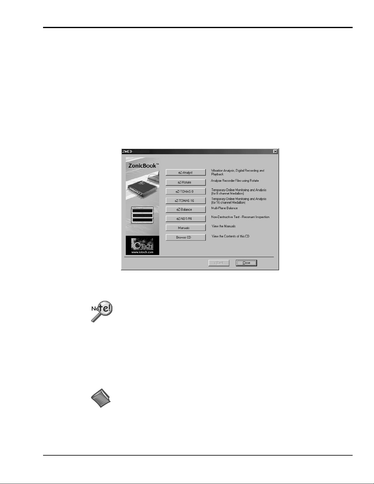
4. A Software and Manuals Selection Screen will appear, similar to the one shown in the
following figure.
Software and Manuals Selection Screen
5. Click the screen button that corresponds with your purchased software.
The Passwords for your software accompany your CD. You will need to enter the
passwords when indicated by the on-screen prompt.
6. Follow the on-screen directions to install your software.
7. Install other ZonicBook software programs, if applicable.
Note: In addition to installing software, you can use the Software and Manuals Selection Screen
(previous figure) to view Adobe PDF versions of ZonicBook documentation. Simply click the
<Manuals> button to access the document files.
Reference Note:
After your software is installed you can setup your ZonicBook Data Acquisition Module and
connect it to the host computer. Instructions for Hardware Setup begin on page 4.
ZonicBook
11-01-01
Getting Started, pg. 3
Page 8
Hardware Setup
D
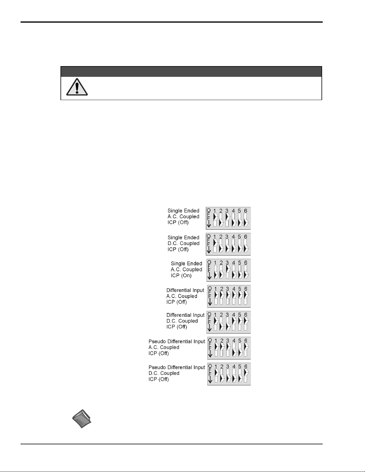
Configuring Channels via DIP-Switches
ZonicBook channel configuration is determined by DIP-switch settings. The default setting is “Single
Ended, A.C. Coupled ICP (Off).” Possible settings are illustrated below.
Each channel must have its associated DIP-switch properly set to achieve the desired
configuration, as determined by your application. Improper settings can damage
your equipment, and will produce erroneous measurements.
To set the switches:
1. Ensure the ZonicBook is disconnected from power, the PC, and all signal lines.
2. Remove ZonicBook’s bottom cover plate.
3. Set each channel’s DIP-switch according to the desired configuration.
Refer to other documentation if needed.
4. Replace the bottom cover plate.
5. For 16-Channel ZonicBook’s only.
(a) After setting the DIP-switches for Channels 1 through 8,
replace the bottom cover plate.
(b) Remove the top cover plate.
(c) Set the DIP-switches for Channels 9 through 16.
(d) Replace the top cover plate.
&$87,21
efault
Channel DIP-Switch Settings
Reference Note:
For convenience, ZonicBook’s bottom cover plate includes illustrations of
the DIP-switch settings.
Getting Started, pg. 4
11-01-01
ZonicBook
Page 9
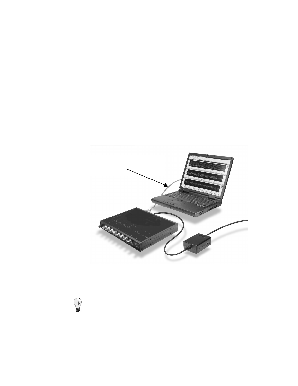
Connecting and Powering a ZonicBook System
It is relatively easy to connect a ZonicBook system, and to supply power to it. The steps are as follows:
1. Insert the DSP-Card into your computer’s PCMCIA slot.
2. Connect the DSP cable to the DSP-Card.
3. Connect the ZonicBook to the DSP-cable.
4. Connect the Power Supply to the ZonicBook.
5. Connect the Power Cord to the Power Supply.
6. Connect the Power Supply to an appropriate power source.
7. Connect the computer to power.
8. Turn on the computer.
9. Turn on the ZonicBook.
A green Power ON LED (on the face of the unit) will light.
DSP-Card with Cable
(DSP-Card, not shown, is in NoteBook’s
PCMCIA Slot)
Notebook PC
with PCMCIA Slot
Power Cord
ZonicBook
Data Acquisition Module
Power Supply
8-Chanel ZonicBook System
Cap unused BNCs to reduce extraneous noise, and to keep the connectors free of
dust and other debris.
ZonicBook
11-01-01
Getting Started, pg. 5
Page 10

Installing ZonicBook Drivers
Only install the drivers that apply to your operating system.
To avoid installing the wrong driver, be sure to use the instructions that are intended for
your PC’s Windows system. Refer to the following sections as applicable.
➣
Windows XP (pg.6)
➣
Windows 2000 (pg. 10)
➣
Windows Me (pg. 14)
➣
Windows95/98 (pg. 17)
➣
Windows/NT (pg. 21)
Note: If you have previously installed ZonicBook drivers, you should not need to do so again,
even if you are upgrading your software.
Windows XP Users
Prior to installing the drivers, be sure that your ZonicBook system is
properly connected and powered.
1. Insert the DSP-Card into your computer’s PCMCIA slot 0.
Windows XP will start the Hardware Wizard.
2. After the dialog box appears, verify that “Install from a list or specific location” is selected.
See following figure.
3. Click <Next>. A new dialog box will appear (following figure).
Getting Started, pg. 6
11-01-01
ZonicBook
Page 11

4. Check “Include this location in the search.”
5. Click <Browse,> then expand the CD-ROM node labeled “IOtech.”
6. Locate and expand the node labeled “Medallion Drivers.”
7. Highlight the “Win2000” folder.
Windows XP Users
ZonicBook
8. Click <Ok>. A dialog box will appear (following figure). The box indicates the driver path.
9. Click <Next>. Windows will locate the device driver, and then install the software.
11-01-01
Getting Started, pg. 7
Page 12

Windows XP Users
10. After the software install is complete, click <Finish>.
The Hardware Wizard will close.
This completes the driver installation for Windows XP. Your computer is now ready to run
ZonicBook software and communicate with the ZonicBook module. After installation is completed,
you can verify that the device has been installed correctly. The verification steps follow.
Verifying the DSP-Card has been Correctly Installed, for Windows XP Users
1. Using the Windows XP Administrator, select the Control Panel.
2. Locate the “System” Icon, and click on it (following figure).
Getting Started, pg. 8
11-01-01
ZonicBook
Page 13

3. In Systems Properties, click on the Hardware tab (following figure).
4. Click on the <Device Manager> button (following figure).
Windows XP Users
ZonicBook
If the device was correctly installed it should appear listed in the device manager
under the CACDSP node.
11-01-01
Getting Started, pg. 9
Page 14

Windows 2000 Users
Prior to installing the drivers, be sure that your ZonicBook system is
properly connected and powered.
1. Insert the DSP-card into your computer’s PCMCIA slot 0.
Windows 2000 will start the Hardware Wizard.
2. After the dialog box appears, click <Next>.
3. Verify that “Search for a suitable driver for my device” is selected, then click <Next>.
4. Check “Specify a location.”
5. Click on the <Next> button.
Getting Started, pg. 10
11-01-01
ZonicBook
Page 15

6. Click <Browse>.
7. Locate and open the “Win2000” folder.
Windows 2000 Users
8. Select the “zonic.inf file.
9. Click <Open> .
ZonicBook
10. Click <Ok>.
11-01-01
Getting Started, pg. 11
Page 16

Windows 2000 Users
11. After the Hardware Wizard indicates that it found
the driver file, Click <Next>.
If the driver was installed correctly, a final dialog box will appear, stating that Windows
has finished installing the driver for DSP.
12. Click <Finish>.
Verifying the DSP-Card has been Correctly Installed, for Windows 2000 Users
Getting Started, pg. 12
This completes the driver installation for Windows 2000. Your computer is now ready to run
ZonicBook software and communicate with the ZonicBook module. After installation is
completed, you can verify that the device has been installed correctly. The verification steps
follow.
1. Click on the start menu and click on Control panel
11-01-01
ZonicBook
Page 17

2. In the control panel, find the <System> Icon and click on it.
3. Click on the Hardware tab (following figure).
4. Click on the <Device Manager> button (following figure).
Windows 2000 Users
ZonicBook
If the device was correctly installed it should appear listed in the device manager
under the CACDSP node.
11-01-01
Getting Started, pg. 13
Page 18

Windows Me Users
Prior to installing the drivers, be sure that your ZonicBook system is
properly connected and powered.
1. Insert the DSP-card into your computer’s PCMCIA slot 0. Windows Me will start the
Hardware Wizard.
2. Verify that the “Specify the location of the driver” option is selected.
3. Click <Next>.
4. In the new dialog box, check “Specify a location.”
Getting Started, pg. 14
5. Click <Browse>.
6. Expand the CD-ROM drive node; then find and open the “Win95-98” folder.
Note: ZonicBook drivers for Windows Me are located in the “Win95-98” folder.
There is not a separate Me folder.
11-01-01
ZonicBook
Page 19

Windows Me Users
A new dialog box, similar to the one below, should appear. The driver path
should appear next to the <Browse> button.
7. Click <Next>. Windows will open a new box, indicating that it has found a
device driver and is ready to install it.
The wizard may recommend using a driver file that is located in the “Win2000”
folder; however, DO NOT use any files from that folder in conjunction with
Windows Me. Windows Me must use the file that is located in the “Win95-98”
folder.
8. Verify that the “One of the other packages” option is selected.
9. Click the <View List> button.
10. From the resulting list, select the driver located in the “Win95-98” location.
The driver description will be “
The location will be *:
\MEDAL~21\WIN95-98\ZONIC.INF
MEDALLION Digital Signal Processor.”
Where: * is the CD-ROM Drive Designation.
11. Click <Ok>. A new dialog box will appear (following figure).
ZonicBook
11-01-01
Getting Started, pg. 15
Page 20

Windows Me Users
12. Click <Next>.
The Hardware Wizard is now ready to install the DSP-card driver
(see following figure).
13. Click <Next>.
14. After the device driver has been installed, click <Finish> (following figure).
This completes the driver installation for Windows Me. Your computer is now ready to run
ZonicBook software and communicate with the ZonicBook module.
Reference Note:
You can use the Windows Control Panel to verify that the DSP-card has been installed
correctly. See, Verifying the DSP-Card has been Correctly Installed, on page 19.
Getting Started, pg. 16
11-01-01
ZonicBook
Page 21

Windows95/98 Users
1. Insert the DSP-Card card into your computer’s PCMCIA slot 0. Windows will start the
2. After the dialog box appears, click <Next>.
3. Verify “Search for the best driver for your device” is selected.
Prior to installing the drivers, be sure that your ZonicBook system is
properly connected and powered.
Hardware Wizard.
ZonicBook
4. Click <Next>.
5. Put a check mark next to “Specify a location.”
6. Click <Browse>; expand the CD-ROM drive node; then locate and open the“Win95-98”
folder. See following figure.
11-01-01
Getting Started, pg. 17
Page 22

Windows95/98 Users
The driver’s location path should appear above the <Browse> button (see following figure).
7. Click <Next>. A new dialog box should appear, as follows.
8. Click <Next> to begin the actual install.
Getting Started, pg. 18
9. Once the device driver has been installed, click <Finish>.
This completes the driver installation for Windows Me. Your computer is now ready to run
ZonicBook software and communicate with the ZonicBook module.
Reference Note:
You can use the Windows Control Panel to verify that the DSP-card has been installed correctly.
See, Verifying the DSP-Card has been Correctly Installed, on page 19.
11-01-01
ZonicBook
Page 23

Verifying the DSP-Card has been Correctly Installed, for Windows 95/98/Me
You can either of two methods to verify that your DSP-card has been correctly installed. Although the
screen shots were taken from Windows 98, the steps for Windows 95 and Windows Me are essentially the
same as those provided below.
The “PC-card” Icon Method
1. From the Windows Desktop, click <Start>.
2. Click Settings.
3. Click Control Panel.
4. In the Control Panel, locate and double-click on the PC-card icon.
ZonicBook
At this point you should see a dialog box similar to following. The box identify the DSP-card
and its associated PCMCIA socket.
This completes the PC-card icon method.
11-01-01
Getting Started, pg. 19
Page 24

Windows 95/98/Me Users
The “System” Icon Method
You can verify that the DSP-card has been properly installed by using the Control Panel’s “System” Icon.
The steps for this method are as follows.
1. From the Windows Desktop, click <Start>.
2. Click Settings.
3. Click Control Panel.
4. Click the System icon.
5. Click the “Device Manager” tab.
6. Locate a node called “D32DSP.”
7. Expand that node by clicking on the “+” symbol.
At this point you should see “MEDALLION Digital Signal Processor” listed below the
D32DSP, as indicated in the following figure.
Getting Started, pg. 20
11-01-01
ZonicBook
Page 25

Windows NT Users
Note: Typically winnt is located on Drive C and often also has a version
Prior to installing the drivers, be sure that your ZonicBook system is
properly connected and powered.
1. Verify that you are logged on with Administrator capabilities.
2. Insert the ZonicBook Suite CD-ROM into your computer’s CD-ROM drive.
3. Open the WinNT folder.
4. Copy the following files to “WINNT\SYSTEM32\”.
cac_cfg.cpl
D32util.dll
number attached as part of the name. i.e. winnt35, winnt40.
5. Copy the following file to “WINNT\SYSTEM32\DRIVERS\”.
cac.sys
6. Reboot your computer. Unless the drivers are already installed, you should see the
“New Hardware Found” message.
7. Click <OK>.
8. Verify IRQ and I/O Port availability. This is done as follows:
(a) From the Start menu, navigate as follows:
Program ⇒ Windows NT Diagnostics ⇒ Resources
(b) Verify and write down the I/O Port Address; for example: 0110-011F
(c) Verify and write down available IRQs; for example: 9, 10, 11.
9. Open the Control Panel.
10. Double-click the CACDSP icon. This opens the CAC API Configuration Utility window.
11. In the data entry box, enter the I/O Port Address [from step 8b].
Typically the I/O Port is either 0x0110 or 0x0120.
12. In the data entry box, enter an available interrupt (IRQ) for your system [from step 8c].
Typically this is 10 or 11.
13. Click the DSP Tab.
14. Select PCMCIA.
15. Click the <ADD> button.
Note: For Windows NT operating systems, the I/O Port Address and IRQ values do not show
up in the menus after you close the window. They are; however, stored in memory.
16. Click <OK.>
17. Restart your computer.
Your computer is now ready to run ZonicBook software and communicate with the
ZonicBook module.
Reference Note:
If the DSP-Card does not respond in Windows NT, refer to the steps on page 22.
ZonicBook
11-01-01
Getting Started, pg. 21
Page 26

Windows NT Users
If the DSP-Card does not respond in Windows NT, try the following:
1. From the desktop, open the Control Panel. This is done by navigating as follows:
Start ⇒ Settings ⇒ Control Panel ⇒ System ⇒ Device Manager ⇒ CACDSP
Note: “CACDSP” represents the DSP-Card device
2. Double-click the “CACDSP” (DSP-Card) device.
3. Click the <Start> button. This starts the DSP-Card without the need to reboot the computer.
4. To enable or disable the DSP-Card, click the <Startup> button, then click the <Enable> or the
<Disable> button as applicable.
5. Click the <HW Profiles> button.
6. If the Startup method is not set to “Automatic,” set the DSP-Card for “Automatic” startup.
Getting Started, pg. 22
11-01-01
ZonicBook
Page 27

Starting the ZonicBook
The ZonicBook system is ready for use once the tasks in the following checklist have been completed.
❑
Software Installed (pg. 3)
❑
Channel DIP-switches Set (pg. 4)
❑
Hardware Connected and Powered ON (pg. 5)
❑
Drivers Installed (pg. 6)
❑
Signal Lines Connected to ZonicBook BNC Connectors for Channel Input
❑
Unused BNC Connectors Capped
To start the ZonicBook system:
1. On the Start Menu, select Programs.
2. Select ZonicBook.
3. Select the applicable ZonicBook software, e.g., eZ-Analyst, eZ-Balance.
Reference Note: Refer to the applicable document module in regard to software specifics.
ZonicBook
11-01-01
Getting Started, pg. 23
Page 28

ZonicBook Specifications
General Specifications
Environment
Operating:
(ZonicBook only)
Storage:
Power Consumption:
supply
Input Power Range:
Dimensions:
(11” x 8.5” x 1.375”)
Weight:
PC-Card (included):
PC-Card to ZonicBook Cable (included):
0° to 50°C, 0° to 95% RH, non-condensing
-20° to 70°C
8.5 watts max with +12 VDC power
9 to +15 VDC
279 mm W x 216 mm D x 35 mm H
1.32 kg (2.9 lbs)
Requires one type III slot
Analog Inputs
Input Channels:
Input Connector:
A/D:
One 16-bit Sigma Delta converter per channel
Sampling:
up to 51.2 kHz max per channel
Digital Decimation Filter:
Dynamic Range:
Amplitude Flatness:
Bipolar Ranges:
Maximum Overvoltage:
Input Bandwidth:
4- and 8-Channel ZonicBook: DC to 20 kHz
16-Channel ZonicBook: DC to 10 kHz
Input Coupling:
AC Coupling:
ICP Voltage (@ 4 mA):
Input Impedance
Single-Ended:
Differential:
Accuracy:
Channel Match:
Input Noise:
Total Harmonic Distortion: -62 dB typ
4, 8, or 16*
BNC
All input channels are sampled simultaneously,
92 dB stop-band attenuation
>80 dB typ
1 dB typ
25 mV to 25V full scale in 1.5 dB steps
±80 VDC
AC, DC; switch selectable, per channel
1.6 Hz; -3 dB point
24V ±.5V (no load), 20V bias max
1M Ohm in parallel with 30 Pf
2M Ohm in parallel with 30 Pf
25 mV to 25V; ±2% (±0.2 dB)
+1 dB amplitude, +1° phase
±3 LSB (RMS)
30 in.
Signal to Noise and Distortion: -60 dB typ
Cross Talk: < 75 dB max; relative to full scale
Anti-Alias Filters: 80 dB alias rejection
Output Characteristics
Number of Channels: 1 BNC output per ZonicBook
Output Frequency Range: 2 kHz
Dynamic Range: 80 dB typ
Frequency Resolution: 0.001 Hz
Frequency Accuracy: 100 ppm
Amplitude Accuracy: 2.0% @ 1V; up to 1 kHz
Maximum Amplitude: 2.8V peak-peak
DAC Resolution: 16-bit Sigma Delta
Processing Characteristics
Analysis Frequency: 10 Hz to 20 kHz for 4- or 8-channel
ZonicBooks; 10 Hz to 10 KHz for 16-channel ZonicBook;
All input channels are sampled synchronous; Analysis
Rate is set for all channels
Blocksize: 128 to 16,384 data samples per block of data
(in powers of 2)
FFT Windows
Response Channels:
Exponential, 3 Term Blackman Harris
Force Channels:
Integration/Differentiation (in frequency domain):
Single and Double Differentiation; Single and Double
Integration
Averaging: Linear, Exponential, Negative, Peak Hold,
Time Synchronous
Acquisition Triggers: Free Run
User-Programmed Trigger:
Time and Date, Pre or Post data trigger delay
Octave Filter: A, B, and C Weighting
Display Types: Time, Trend, Auto Spectrum, Cross
Spectrum, Spectrum, FRF, PSD, Transfer Function, 1/3
Octave, Full Octave, Coherence
Transfer Function Types: Inertance, Mobility,
Compliance, Apparent Mass, Impedance, Dynamic
Stiffness
Octave Types: 1/3, Full
None, Hanning, Flat Top,
None, Rectangular, Cosine Taper
Level and Slope,
Getting Started, pg. 24
11-01-01
ZonicBook
 Loading...