

Page 1
WBK40 and WBK41
Thermocouple & Multi-Function I/O Modules
For use with WaveBook/516E and WBK25
Overview ….. 1
What are WBK40 and WBK41? …… 1
Front Panel Connectors …… 2
Rear Panel Connectors ….. 4
Setup …… 5
Hardware Setup …… 5
Software Setup …… 14
Operational Aspects ...... 14
Block Diagrams …… 14
Thermocouple Measurements …… 15
Digital I/O, WBK41 Only …… 16
Synchronous Input Operations …… 16
Output Channel Configuration …… 17
Asynchronous I/O Operations …… 18
Analog Outputs, WBK41 Only (DBK46 Required) …… 19
Using a Temperature Calibrator …… 20
CE Compliance …… 21
Fuse Replacement …… 23
P1 - DB37 Connector Pinout …… 26
P2 – DB37 Connector Pinout (WBK41 Only) …… 27
Specifications …… 28
WBK40 & WBK41 Installation Guide
(p/n 1066-0901)
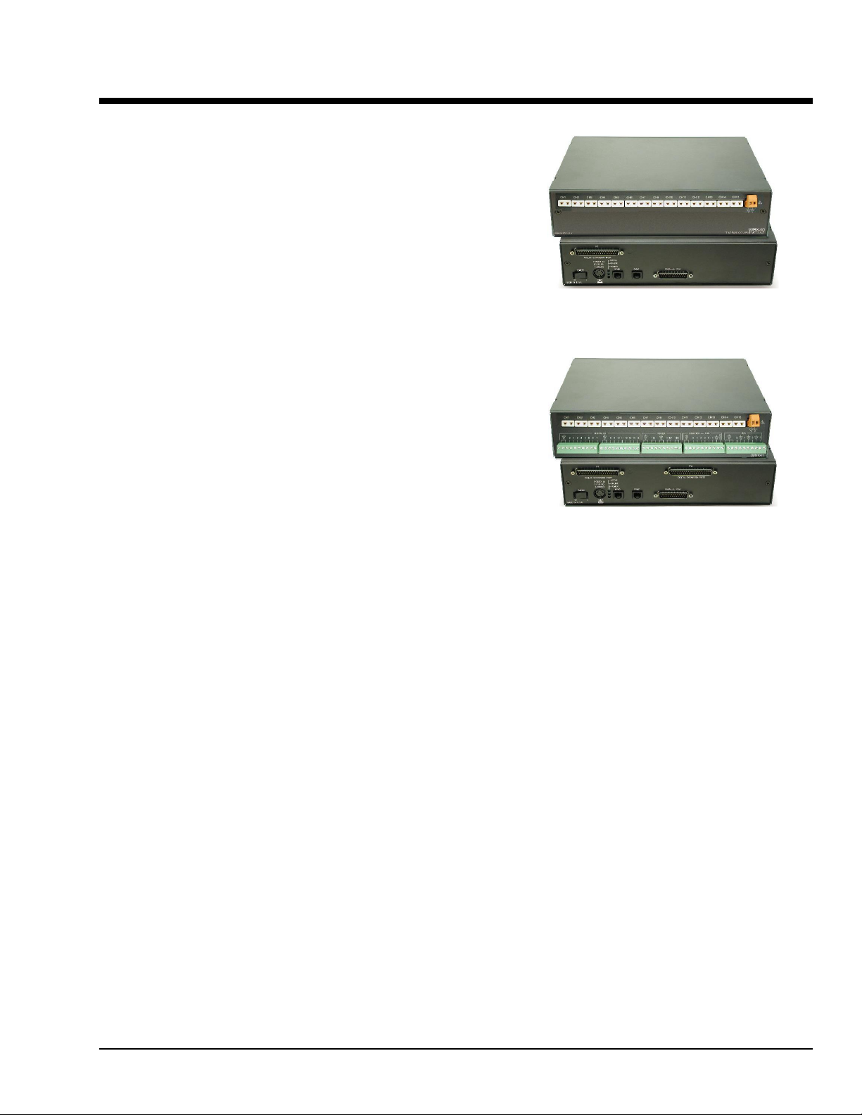
14 Channel Thermocouple Input Module,
WBK40
Front & Rear Views
WBK41
Multi-Function Thermocouple I/O Module,
Front & Rear Views
Overview
What are WBK40 and WBK41?
The WBK40 is a 14-Channel Thermocouple Input Module. The WBK41 is a Multi-Functional I/O Module. The
latter includes the thermocouple functionality of the WBK40 and additional features, as will be discussed shortly.
Both the WBK40 and WBK41 attach to any one of the three DB25 parallel expansion ports on a WaveBook/516E
or WBK25. Because the modules each have a built-in 16 bit, 200-kHz A/D converter, measurements do not
consume valuable sampling time from the host WaveBook’s 1-MHz A/D converter. For this reason, there are no
speed implications to WaveBook [or other WBK] measurements when a WBK40 or a WBK41 is attached.
Measurements can be made synchronous with the WaveBook/516E, providing precise time correlation between
readings from both measurement devices.
Features common to WBK40 and WBK41
Provides a means of adding from 14 to 224 thermocouple inputs to the WaveBook/516E or WBK25
•
Provides linearized and cold-junction compensated readings for all thermocouple types
•
Exhibits 1.0°C [or better] accuracy for most ranges and TC types
•
Consumes no measurement bandwidth from the WaveBook/516E
•
Detects open thermocouples
•
Additional features of the WBK41
16 Digital I/O Lines (via front panel screw-terminal blocks)
•
24 Digital I/O Lines (via a rear panel 37-pin connector, P2)
•
4 Counter Inputs (via front panel screw-terminal blocks)
•
2 Timer Outputs (via front panel screw-terminal blocks)
•
4 Channel, 16-bit, 100 kHz Analog Output (via front panel screw-terminal
•
blocks; but only when a factory-installed DBK46 option is in place)
Thermocouple & Multifunctional Modules
WBK40 & WBK41, pg. 1
926896
Page 2
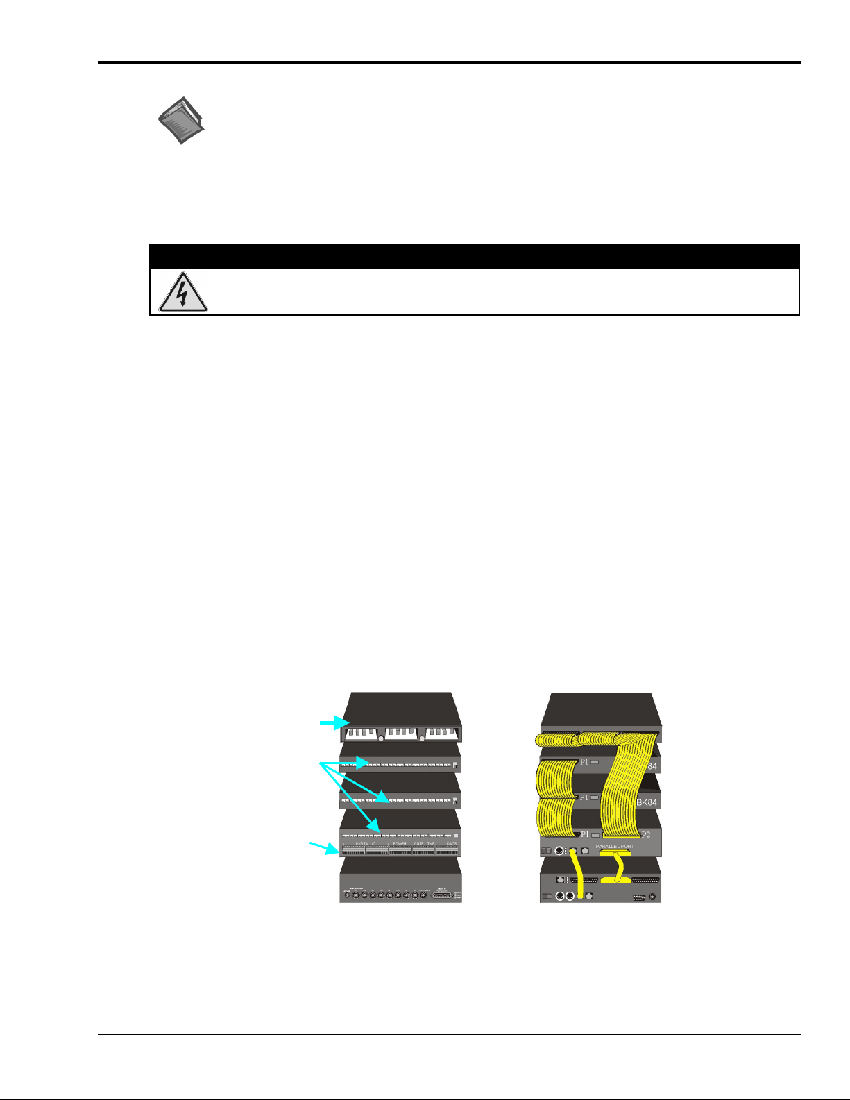
Front Panel Connectors
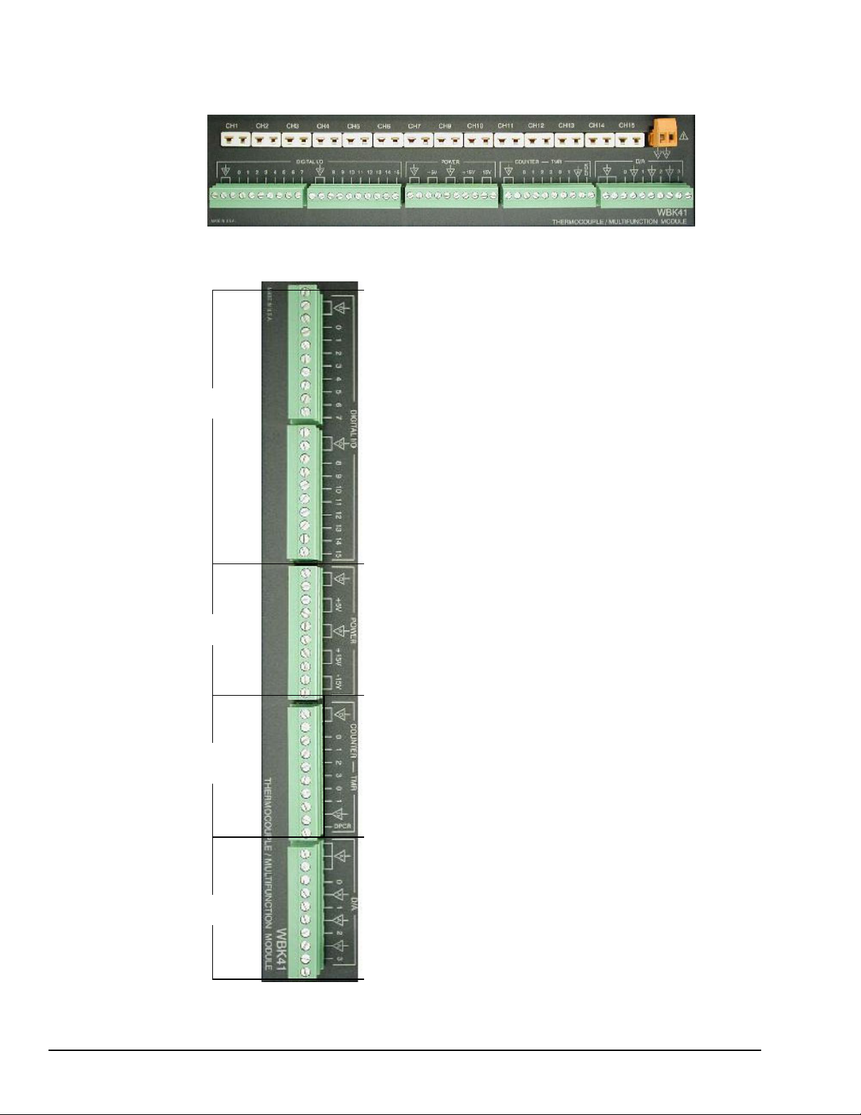
WBK41 Front Panel
Note that the WBK40’s Front Panel is identical, except it has no Screw-Terminal Blocks (see pg. 3).
WBK41, Front Panel Connectors
DIGITAL I/O
POWER
COUNTER /
TIMER
DACs
pg. 2, WBK40 & WBK41
DCOM
DCOM
Digital I/O, CH0
Digital I/O, CH1
Digital I/O, CH2
Digital I/O, CH3
Digital I/O, CH4
Digital I/O, CH5
Digital I/O, CH6
Digital I/O, CH7
DCOM
DCOM
Digital I/O, CH8
Digital I/O, CH9
Digital I/O, CH10
Digital I/O, CH11
Digital I/O, CH12
Digital I/O, CH13
Digital I/O, CH14
Digital I/O, CH15
DCOM
DCOM
+5V
+5V
ACOM
ACOM
+15V
+15V
-15V
-15V
DCOM
DCOM
Counter Input 0
Counter Input 1
Counter Input 2
Counter Input 3
Timer Output 0
Timer Output 1
DCOM
DPCR
ACOM
ACOM
ACOM
DAC0
ACOM
DAC1
ACOM
DAC2
ACOM
DAC3
The first two terminal blocks include connections
for DCOM (Digital Common) and Digital I/O
channels 0 through 15. 24 additional Digital I/O
lines are available from P2 on the rear panel
(WBK41 only), providing that P2 is not used for
DBK20 Series expansion.
In addition to DCOM (Digital Common) and ACOM
(Analog Common) Connections, the Power
terminal block provides general use power
connections of the following values: +5V, +15V,
and -15V. Power drawn from this terminal block
reduces the total power available for expansion
options.
The Counter/Timer terminal block provides three
Digital Common connectors, four Counter Input
connectors, two Timer Output Connectors, and
one connector for an External DAC Pacer Clock
(DPCR).
The DPCR connection allows the user to supply
an external input clock to pace the DACs.
The DACs terminal block includes six ACOM
(Analog Common) connectors and four connectors
for DACs (Digital-to-Analog Converters). The
DACs are designated:
DAC0, DAC1, DAC2, and DAC3. They are only
available if the DBK46 analog output option is
installed. Note that the DBK46 option is a Factoryinstall option only. Refer to the DBK46 section of
this document module for additional information.
Thermocouple and Multifunctional Modules
926896
Page 3
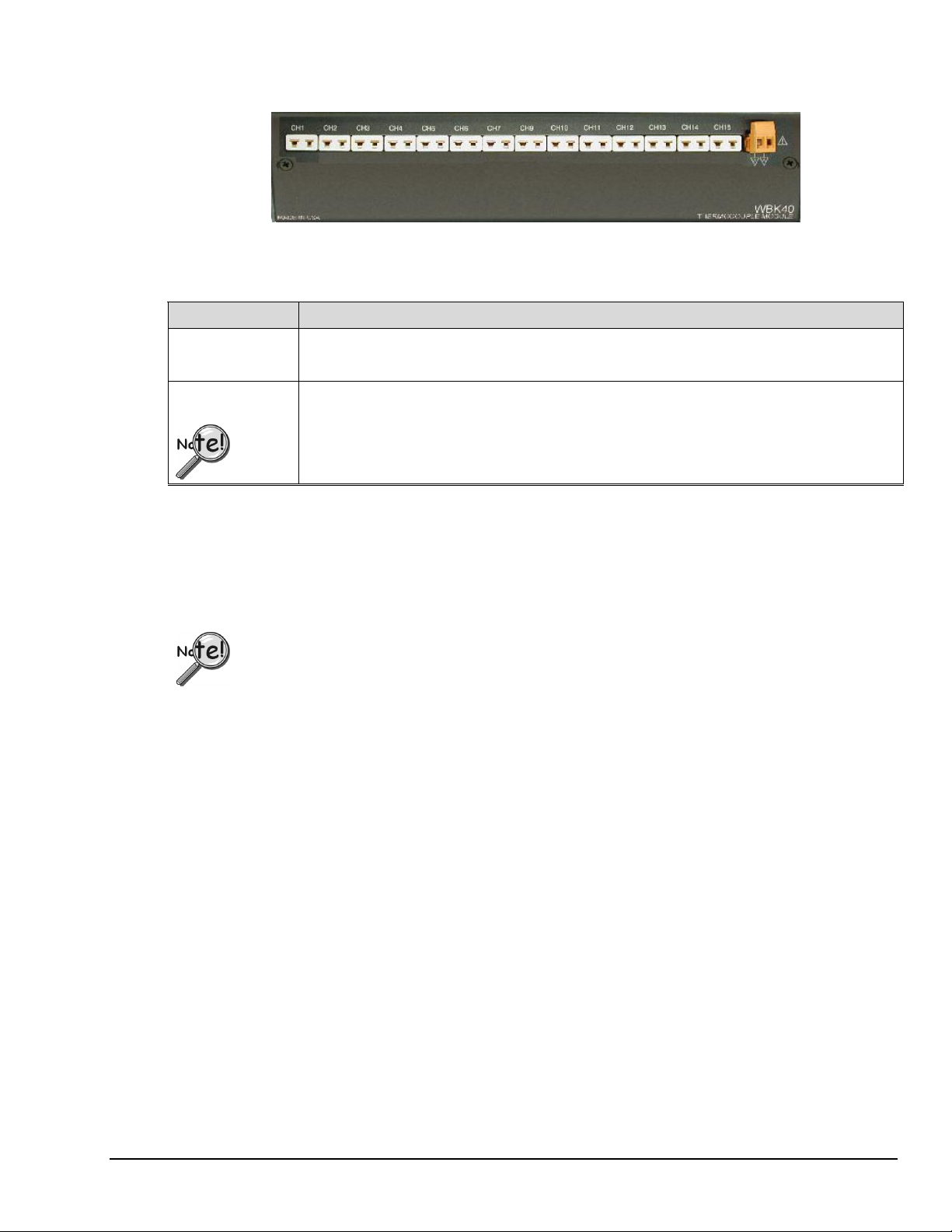
WBK40 Front Panel
WBK40 Front Panel Connectors
The Mini-TC and Analog Common Connectors exist on both the WBK40 and WBK41 Modules.
Item Description (Applies to both WBK40 and WBK41)
through
CH1
Mini-TC Connectors
Analog
Common
CH15
This row contains 14 mini-TC connectors. These are for connecting thermocouples to channels 1 through
7 and to channels 9 through 15. Channels 0 and 8 have no mini-TC connectors, as these two channels
are used for cold-junction compensation (CJC).
Analog Common. This is a dual-pin receptacle located next to the Channel 15 TC connector.
A typical use of the ACOM connection would be to attach the shield of a shielded thermocouple.
If a thermocouple shield is connected to a WBK40 [or WBK41] module, leave the shield
unconnected at the other end of the thermocouple to avoid a ground loop.
The modules’ built-in TC channels are accessed via mini-TC connectors on the front panel. This is true for both the
WBK40 and the WBK41. The 14 built-in TC channels can accept any type of thermocouple, including types J, K, S,
T, E, B, R, and N. The units can be expanded in 14-channel increments using DBK84 TC expansion modules. A
total of 15 DBK84s can be attached to one WBK40 [or WBK41], for a total TC channel capacity of 224 channels.
If more than eight DBK84 modules are to be connected to one WBK40 [or WBK41], additional
power must be supplied. The power can be obtained from DBK32A or DBK33 Auxiliary Power
Supply Cards, housed within a DBK10 expansion chassis.
WBK41’s Counter/Timer functions and 16 bits of Digital I/O are accessed via removable front panel screw-terminal
connectors (see previous figure). Additional Digital I/O and expansion connectors are located at the rear of the
WBK41, as indicated in the following figure.
The WBK41 can be easily expanded beyond its built-in channel capacity. WBK41 systems can include:
up to 224 TC Input Channels by connecting to 15 DBK84 modules •
•
up to 208 Digital I/O Channels by connecting to 4 DBK20 Series cards or up to
272 Digital I/O channels by connecting to 8 DBK208 expansion boards
•
4 Analog Output channels when a DBK46 DAC option card is installed
•
4 Counter Input channels and 2 Timer Output channels
Thermocouple & Multifunctional Modules
WBK40 & WBK41, pg. 3
926896
Page 4
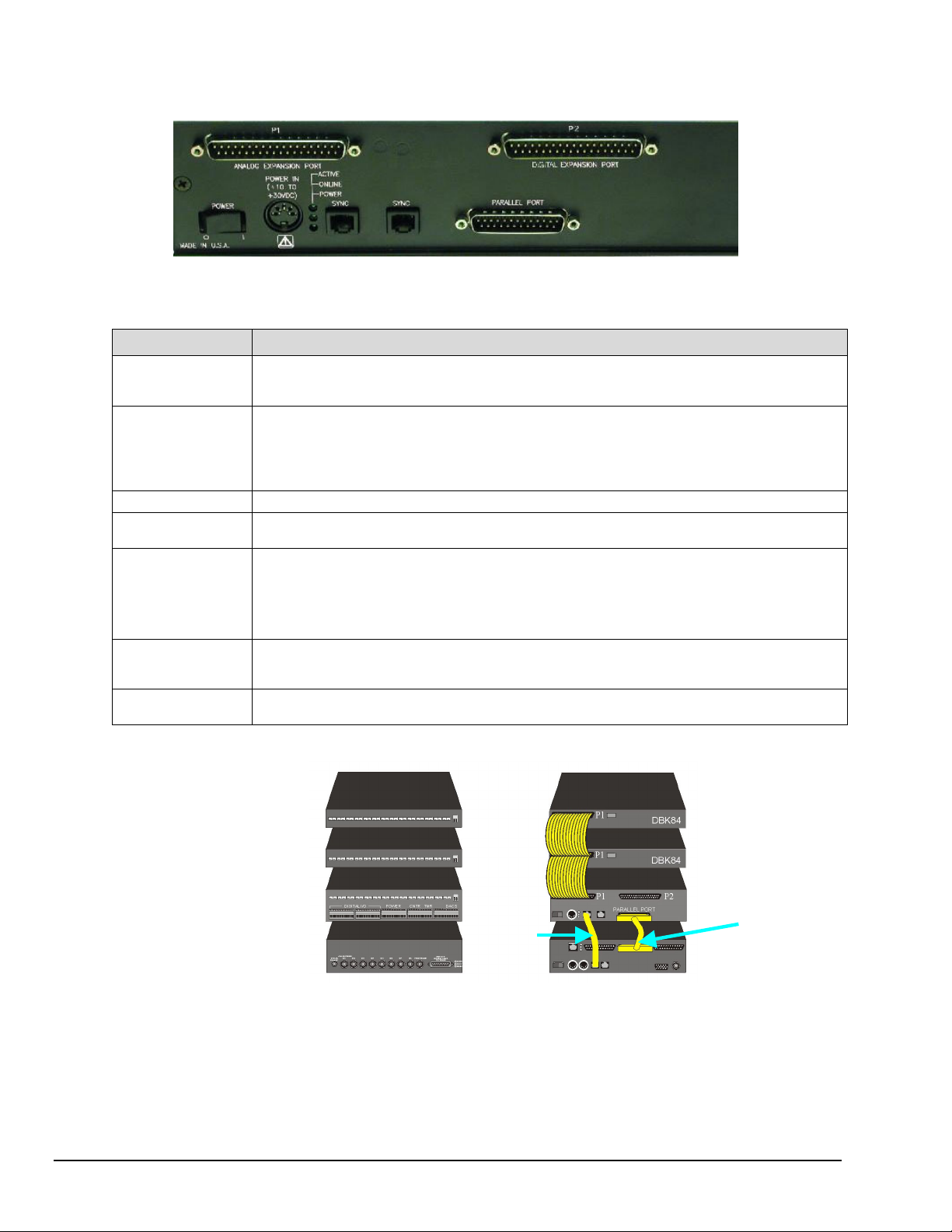
Rear Panel Connectors
:
Note
The P2 Connector
does not apply to
WBK40.
Note that WBK40’s Rear Panel is identical, except it has no P2 connector. Page 1 includes a photo of the WBK40 rear panel.
WBK41, Rear Panel Connectors
Item Description
P1
(see page 26 for
pinout)
(WBK41 Only)
P2
(see page 27 for
pinout)
POWER [switch]
POWER IN
LEDs
SYNC Ports (2)
PARALLEL PORT
P1 is an Analog Expansion Port. This DB37 connector is used to connect the WBK40 or WBK41 to an
optional DBK84, 14-Channel Thermocouple Module. The connection is typically made via a CA-37-x
ribbon cable, where “x” equals the number of analog expansion devices.
P2 is a Digital Expansion Port, which is available on the WBK41, but not on the WBK40. This DB37
connector can be used to connect the WBK41 to an optional DBK20 Series device. The connection is
typically made via a CA-37-x ribbon cable, where “x” equals the number of digital expansion devices.
If P2 is not used for DBK20 Series expansion, it allows for 24 bits of Digital I/O, which is in addition to the
16 bits of Digital I/O that are provided by front panel terminal blocks.
Two-position rocker switch with labels “0” for “Power OFF” and “1” for “Power ON.”
A DIN5 connector which accepts power of +10 to +30 VDC. Power is typically supplied via a
TR-40U power adapter.
ACTIVE – Lights when a sample is being converted by the Analog-to-Digital Converter (ADC) that resides
inside the WBK40 or WBK41.
ONLINE – Lights when software is communicating with the WBK40 or WBK41.
POWER – Lights when power is available to the WBK40 or WBK41, and the Power switch is in
the “1” (Power ON) position.
Two SYNC Ports are available to synchronize sampling with other connected devices that have SYNC
ports, for example, the WaveBook/516E. Cable CA-74-1 or CA-74-5 is typically used to provide
a synchronization link from a WBK40 [or WBK41] module to another device.
The Parallel Port is a DB25 connector that is used to connect the WBK40 [or WBK41] to a
WaveBook/516E or WBK25 Ethernet Interface Module.
DBK84
DBK84
WBK41
WaveBook/516E
Channel Input Side Device Interface Side
One of Many Possible WBK41-Based Systems
Note 1: Each DBK84 module requires a unique address setting as explained on page 13.
pg. 4, WBK40 & WBK41
(Note 1)
CA-35-12
CA-37-1T
CA-37-1T
CA-74-1
DBK84
DBK84
WBK41
WaveBook/516E
Thermocouple and Multifunctional Modules
926896
Page 5
Setup
Reference Note
For a quick set up involving connecting a WBK40 or a WBK41 to a WaveBook/516E or to a
WBK25, refer to the WBK40 & WBK41 Installation Guide (p/n 1066-0901). For convenience,
a copy has been placed after the specifications section of this document.
Hardware Setup, for WBK40 and WBK41
Electrical Shock Hazard! To avoid possible injury and equipment damage, turn off power to
devices and connected equipment prior to setup.
Connecting to the Channel Input Side
WBK40 and WBK41 each have a row of 14 mini-TC connectors. These are for connecting thermocouples to
channels 1 through 7 and to channels 9 through 15. Channels 0 and 8 have no mini-TC connectors, as these two
channels are used for cold-junction compensation (CJC). The connection information regarding thermocouples is
included in the upcoming sub-sections, Thermocouple Connections (page 6) and Open Thermocouple Detection
(page 7).
In addition to thermocouple connections, the WBK41 can accept signal lines for the following:
WARNING
16 Digital I/O Lines (via front panel screw-terminal blocks)
•
24 Digital I/O Lines (via a rear panel 37-pin connector, P2)
•
4 Counter Inputs (via front panel screw-terminal blocks)
•
2 Timer Outputs (via front panel screw-terminal blocks)
•
4 Channel, 16-bit, 100 kHz Analog Output (via front panel screw-terminal blocks;
•
but only when a factory-installed DBK46 option is in place)
System Example
144 Digital I/O
(via 3 DBK21 Cards in a DBK10 Chassis)
14 Thermocouples
each DBK84 and to the WBK41 (or WBK40).
For WBK41
(CNTR), Timer Output (TMR), and Analog
Output (DACS) lines can be connected to
the associated terminal block screw
connectors. (See following photo.)
can be connected to
: Digital I/O, Counter Input
DBK10 with
3 DBK21 Cards
DBK84
(Note 1)
DBK84
WBK41
WaveBook/516E
Channel Input Side Device Interface Side
One of Many Possible WBK41-Based Systems
Note 1: Each DBK84 module requires a unique address setting as explained on page 13.
Thermocouple & Multifunctional Modules
WBK40 & WBK41, pg. 5
926896
Page 6
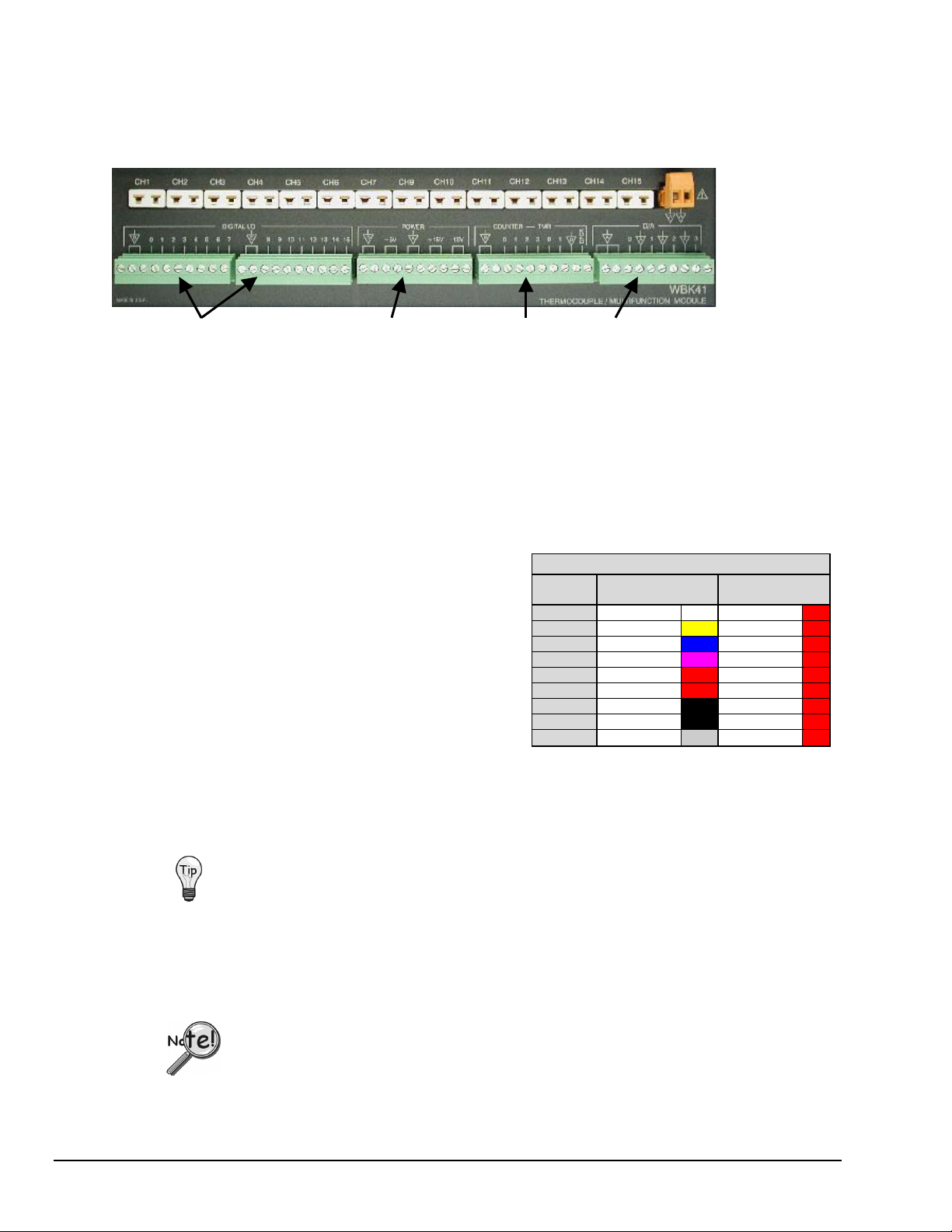
:
Note
The row of terminal
blocks does not
apply to WBK40.
DIGITAL I/O (2 Terminal Blocks) POWER [Out] COUNTER - TMR D/A (DAC0, DAC1, DAC2, DAC3)
WBK41, Front Panel Connectors
Note that WBK40’s Front Panel is identical, except it has no screw-terminal blocks. Page 1 includes a photo of WBK40.
Page 2 includes a table that describes each item found on the front panel.
Thermocouple Connections
The WBK40 and WBK41 each accept up to 14 thermocouples [with mini-TC plugs] via channels 1
through 7 and 9 through 15. All channels have the same level of functionality.
Thermocouple wire is standardized, color-coded, and polarized, as noted in the following table.
Mini-TC plugs are type-specific, and for best
measurement operation the plug TC type should match
the wire TC type. If necessary, copper/copper (Type U)
plugs may be used, but measurement stability will be
slightly degraded. Mini-TC plugs are polarized as well,
and it is critical for proper measurement operation that
this polarity be followed when connecting the
thermocouple wire. Once wired, the TC plugs will only
mate into the unit’s TC connectors in one orientation,
thus ensuring a correct connection.
T/C
Type
N28 Orange Red
N14 Orange Red
Thermocouple Standards
(+) Lead to
Channel High
J White Red
K Yellow Red
T Blue Red
E Violet Red
S Black Red
R Black Red
B Gray Red
(-) Lead to
Channel Low
It should be noted that thermocouples output very small voltages and that long thermocouple leads can
pickup a large amount of noise. However, both the WBK40 and WBK41 inherently provide a high level of
noise immunity via their 4 Hz signal bandwidth and input filtering. If desired, further noise reduction can
be achieved through the use of shielded thermocouples and/or averaging.
You can minimize the effect of noise by:
(1) using shielded thermocouples
(2) averaging readings
(3) employing both of the above practices
To accommodate shielding, grounded connections, labeled “Analog Common,” are provided. A typical
use of the connection would be to attach the shield of a shielded thermocouple. Note that the Analog
Common connector is removable to facilitate wiring.
If a thermocouple shield is connected to a WBK40, or WBK41 module, leave the shield
unconnected at the other end of the thermocouple.
pg. 6, WBK40 & WBK41
Thermocouple and Multifunctional Modules
926896
Page 7

Open Thermocouple Detection
The WBK40, WBK41, and DBK84 modules are equipped with open thermocouple detection for each
channel. This means that a broken thermocouple wire [or otherwise unconnected input] that is measured
will result in an off-scale reading. This is accomplished by applying a small bias current to each of the
channel inputs. Whenever a valid input is absent, the bias current saturates the input amplifier, resulting in
the off-scale reading. When in this “off-scale” state, however, the input amplifier draws more current from
the power supply. Specifically, the power draw of the module from ±15 V will increase by 0.75 mA for
each open channel.
If available power is limited, insert shorted TC plugs into unused channels. This will
minimize power consumption. Note that it is not enough to simply avoid scanning unused
channels; to minimize power consumption the channels must be physically shorted in the
hardware.
The power requirements, detailed in the product specification, assume worst case
connection conditions.
Digital I/O, Power, Counter/Timer, and DAC Connections (WBK41 Only)
The front panel of the WBK41 includes removable plug-in screw-terminal blocks for Digital I/O, Power,
Counter/Timer, and DAC (see following picture). Note that the DACs are only available if the DBK46
option is installed. Signal assignments are provided on page 2.
DIGITAL I/O (2 Terminal Blocks) POWER [Out] COUNTER - TMR D/A (DAC0, DAC1, DAC2, DAC3)
WBK41, Front Panel Connectors
CAUTION
Signal mix-up will result in erroneous readings and can damage equipment. Be sure to
connect signal lines to the proper screw-terminal connections.
Never move a wired terminal block from its intended terminal block socket to another.
The improperly routed signals, which result, can cause equipment damage.
Thermocouple & Multifunctional Modules
WBK40 & WBK41, pg. 7
926896
Page 8
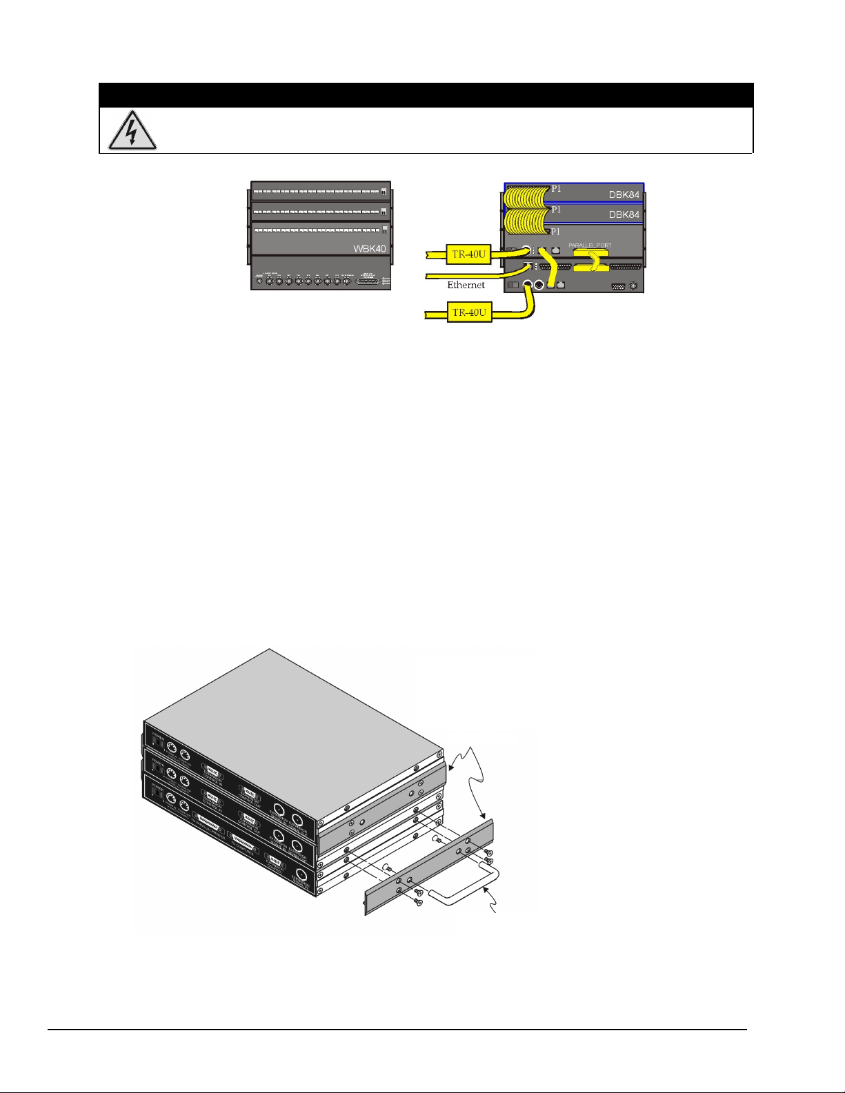
Connecting to the Device Interface Side –
WARNING
Electrical Shock Hazard! To avoid possible injury and equipment damage, turn off power to
devices and connected equipment prior to setup.
DBK84
DBK84
WBK40
WaveBook/516E
WBK40 System Examples
Note 1
Channel Input Side Device Interface Side
A WaveBook/516E with a WBK40 and two DBK84 Modules
Note 1: Each DBK84 module requires a unique address setting as explained on page 13.
Device Interface Connections (seen in the above example):
1.
From the WBK40 P1 connector to two DBK84 Modules via two CA-37-1T cables.
(Page 10 discusses T-Cables)
2. From a WBK40 SYNC port to a WaveBook/516E SYNC Port via a CA-74-1 cable.
3. From a WaveBook/516E EXPANSION PORT to the WBK40 PARALLEL PORT
via a CA-35-12 cable.
4. From the WaveBook/516E ETHERNET port to the Ethernet via a CA-242 cable.
5. Power Supply – a TR-40U was connected to the POWER IN [DIN 5] connector to supply power
at +10 VDC to +30 VDC for the WBK40 and for the WaveBook/516E.
Using Fastener Panels to Stack Modules:
Fastener Panels, sometimes referred to as “splice plates” (p/n 262-0801 and p/n 232-0810) are
typically used to stack modules to WaveBooks, and/or other modules. Optional handles
(p/n HA-111) may also be attached to a system. The following figure illustrates the simplicity
of the mounting process.
The fastener panels and associated screws are from
fastener panel kit p/n 262-0801 for connecting WBK
modules or p/n 232-0810 for connecting DBK84
modules.
Fastener Panels
Using Fastener Panels to Stack a WaveBook and two WBK Modules (use of the handle is optional)
Note:
When used with a WBK16, WaveBook/516, WaveBook/516A, or WaveBook/512A, fastener
panels will partially block the vents on the side of the module. This partial blocking of vents
does not jeopardize the cooling process.
pg. 8, WBK40 & WBK41
The optional handle is p/n HA-111.
Thermocouple and Multifunctional Modules
926896
Page 9
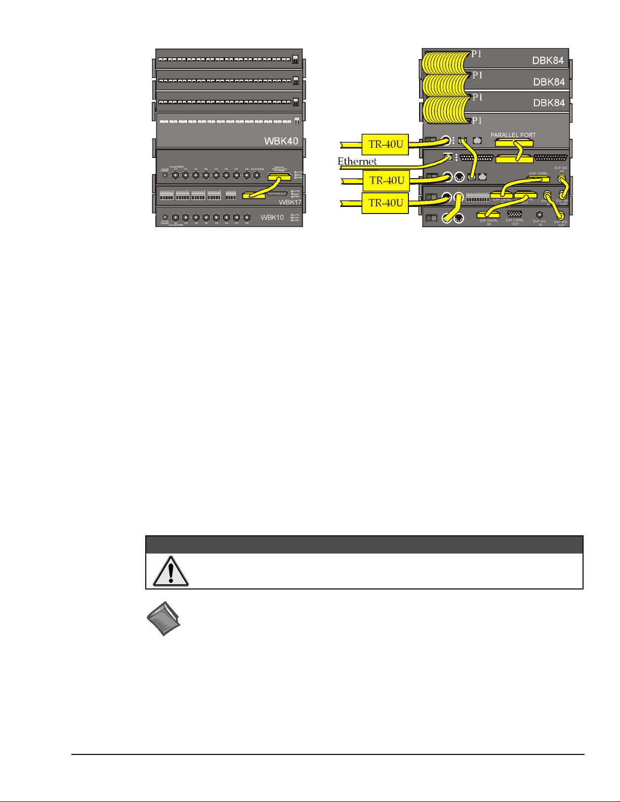
DBK84
DBK84
DBK84
WBK40
WaveBook/516E
WBK17
WBK10A
Channel Input Side Device Interface Side
A WaveBook/516E with a WBK17, WBK10A, WBK40, and three DBK84 Modules
Device Interface Connections (seen in the above example):
1. From the WBK40 P1 connector to three DBK84 Modules via three CA-37-1T cables.*
2. From the WBK40 SYNC port to WaveBook/516E SYNC Port via a CA-74-1 cable.
3. From the WBK40 PARALLEL PORT to the WaveBook/516E Expansion Port via a CA-35-12 cable.
4. From the WaveBook/516E’s ETHERNET port to the Ethernet via a CA-242 cable.
5. From the WaveBook/516E EXTERNAL CONTROL connector to the WBK17’s EXPANSION
CONTROL IN connector, via a CA-129 cable.
6. From the WaveBook/516E EXTERNAL SIGNAL IN connector to the WBK17 EXTERNAL
SIGNAL OUT connector via a CA-150 cable.
7. From the WaveBook/516E Channel Input Side’s DIGITAL I/O AND TRIGGER connector to the
WBK17 DIGITAL EXPANSION IN connector via a CA-217 cable.
8. From the WBK17 EXPANSION CONTROL OUT connector to the WBK10A EXPANSION
CONTROL IN connector via a CA-129 cable.
9. From the WBK17’s EXPANSION SIGNAL IN connector to the WBK10A’s EXPANSION SIGNAL
OUT connector via a CA-150 cable.
10. Power Supply – a TR-40U was connected to the POWER IN [DIN 5] connector to supply power at
+10 VDC to +30 VDC for the WBK40, WaveBook/516E, and WBK17.
Note 1
11. Power Supply – From the WBK17 POWER OUT [DIN 5] +10 VDC to +30 VDC connector to the
WBK10A POWER IN [DIN 5] connector via a CA-115 power cable. The CA-115 is a 6-inch long
cable which has a 5-pin DIN male connector at each end.
An incorrect use of power can damage equipment or degrade performance. Prior to
connecting your devices to power, calculate your system’s power requirements.
Reference Note
Information pertaining to connecting the system to power and calculating the amount of
power needed can be found in the WaveBook User’s Manual. A PDF version is included on
the data acquisition CD and can be accessed from the CD’s intro-screen by using the <View
PDFs> button.
* Information regarding the use of CA-37-T cables is provided on page 10.
Using Fastener Panels to Stack Modules:
Fastener panels are illustrated and discussed on page 8.
Note 1: Each DBK84 module requires a unique address setting as explained on page 13.
Thermocouple & Multifunctional Modules
CAUTION
WBK40 & WBK41, pg. 9
926896
Page 10
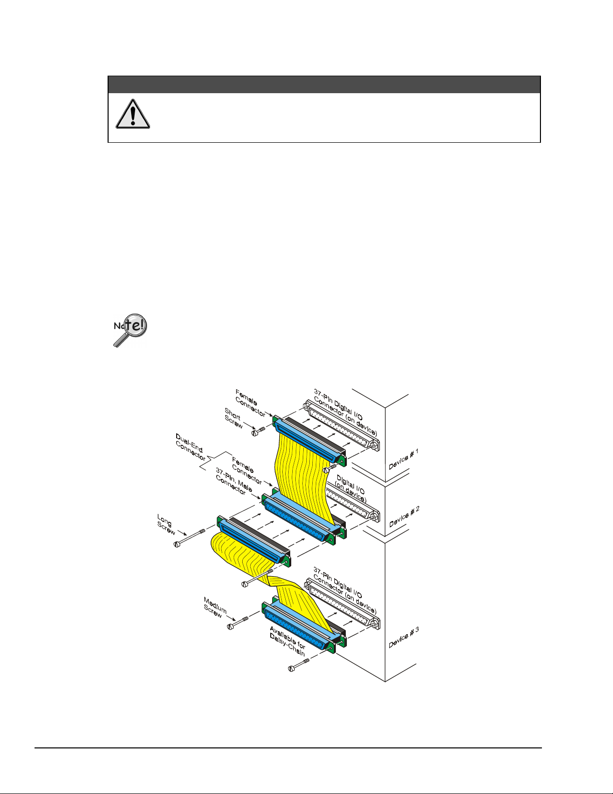
What are “T-Cables” and how are they used?
D
y
A T-Cable is a ribbon cable that extends the connections of one of the ports it plugs into, thus allowing a
second cable to plug into that port. The following figure clarifies the concept.
T-Cables are available in different lengths and can be used for linking two or more compatible devices
together via the device’s 37-pin connectors.
The bottom-end of the T-Cable is a dual-connector, consisting of both a female connector, and a 37-pin
(male) connector. As seen in the following illustration, the T-Cable’s 37-pin (male) connector can be used
for “Daisy-Chain” applications.
Each T-Cable comes with three sets of screws. These are designated (in the diagram) as: short, medium,
and long. Use the short screws to secure the single, female-end of the cable to the device; and use the
medium length screws to secure a cable’s “dual-end” connector. Use the long screws for daisy-chain
applications (when you are connecting one T-Cable to another T-Cable).
Turn power OFF to the acquisition devices and to externally connected equipment
prior to connecting cables. Electrical shock or damage to equipment can result even
under low-voltage conditions.
Tighten screws snug only; do not over-tighten!
CAUTION
ais
-Chain Example, Using Tw
Using two T-Cables to Connect Three Devices
Daisy-Chain Example
o T-Cables
pg. 10, WBK40 & WBK41
Thermocouple and Multifunctional Modules
926896
Page 11
Connecting to the Device Interface Side –
Electrical Shock Hazard! To avoid possible injury and equipment damage, turn off power to
devices and connected equipment prior to setup.
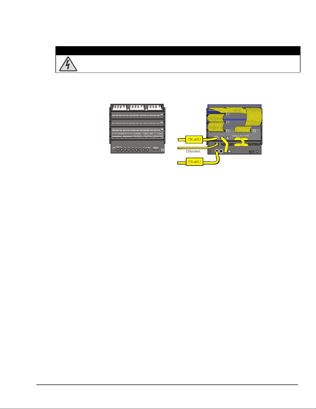
WBK41 System Examples
WARNING
3 DBK21 Cards in a DBK10
DBK84
DBK84
WBK41
WaveBook/516E
A WaveBook/516E with a WBK41, two DBK84 Modules, & three DBK21 Cards (in a DBK10)
Device Interface Connections (seen in the above example):
1. From the WBK41 P1 connector to two DBK84 Modules via two CA-37-1T Cables.*
2. From a WBK41 SYNC port to a WaveBook/516E SYNC Port via CA-74-1 Cable.
3. From the WaveBook/516E EXPANSION port to the WBK41 PARALLEL PORT via a
CA-35-12 cable.
4. From the WaveBook/516E ETHERNET port to the Ethernet via a CA-242 cable.
5. From the WBK41 P2 connector to three DBK21 Cards (in a DBK10 Chassis) via a
CA-37-3 cable.
6. Power Supply – a TR-40U was connected to the POWER IN [DIN 5] connector to supply
power at +10 VDC to +30 VDC for each of the following devices:
* Information regarding the use of CA-37-T cables is provided on page 10.
Note 1
Channel Input Side Device Interface Side
• • WBK41
WaveBook/516E
Using Fastener Panels to Stack Modules:
Fastener Panels are discussed on page 7.
Note 1: Each DBK84 module requires a unique address setting as explained on page 13 of this document
module and in the DBK Options User’s Manual (p/n 457-0905). Each DBK21 card also requires a
unique address as dicsussed in the DBK Options User’s Manual.
Thermocouple & Multifunctional Modules
WBK40 & WBK41, pg. 11
926896
Page 12

DBK84
Note 1
WBK41
WaveBook/516A
WBK25
Channel Input Side Device Interface Side
A WaveBook/516A with a WBK25, WBK41, and DBK84
Device Interface Connections (seen in the above example):
1. From the WBK41 P1 connector to the DBK84 Module via one CA-37-1T Cable.*
2. From a WBK41 SYNC port to a WaveBook/516A SYNC Port via CA-74-1 Cable.
3. From the WBK41 PARALLEL PORT connector to the WBK25 EXPANSION PORT 2 connector via a
CA-35-12 cable.
4. From the WaveBook/516A PARALLEL PORT to the WBK25 EXPANSION PORT 1 connector via a
CA-35-12 cable.
5. From the WBK25 ETHERNET port to the Ethernet via a CA-242 cable.
6. Power Supply – a TR-40U was connected to the POWER IN [DIN 5] connector to supply
power at +10 VDC to +30 VDC for the WBK41 and the WaveBook/516A.
7. Power Supply – From the WaveBook/516A’s POWER OUT [DIN 5] +10 VDC to +30 VDC connector to
the WBK25’s POWER IN [DIN 5] connector via a CA-115 power cable. The CA-115 is a 6-inch long
cable which has a 5-pin DIN male connector at each end.
CAUTION
An incorrect use of power can damage equipment or degrade performance. Prior to
connecting your devices to power, calculate your system’s power requirements.
Reference Note
Information pertaining to connecting the system to power and calculating the amount of
power needed can be found in the WaveBook User’s Manual. A PDF version is included on
the data acquisition CD and can be accessed from the CD’s intro-screen by using the <View
PDFs> button.
* Information regarding the use of CA-37-T cables is provided on page 10.
Using Fastener Panels to Stack Modules:
Fastener Panels are discussed on page 7.
Note 1: Each DBK84 module requires a unique address setting as explained on page 13.
pg. 12, WBK40 & WBK41
Thermocouple and Multifunctional Modules
926896
Page 13

Setting “Unique” Channel Addresses for DBK84 Modules
All DBK84 modules that are connected to WBK40 or WBK41 systems must have unique channel address
settings. Unlike the WBK40 and WBK41, which are internally pre-set with an address of “0,” each
DBK84 module requires that the address be set via DIP switches located on the front panel of that module.
CAUTION
Adjustment of the channel address must only be performed when the system
power is OFF. Failure to do so may result in equipment damage.
DBK84 modules that are connected to a WBK40 or WBK41 must have their addresses physically set to a
value between 1 and 15, inclusive. Four micro-switches [on a DIP switch] are used to set the module’s
channel address in binary.
Set a DBK84 address as follows:
1. Locate the DIP switch. It is just to the right of the P1 connector.
2. Ensure system power is OFF.
3. Adjust the micro-switches to set the desired address. Refer to the following figure.
Address “0” is used by WBK40 and WBK41 and is not to be assigned to a DBK84
that is part of a WBK40 or WBK41 system. Each connected DBK84 must have a
unique address. The following figure shows the complete range of switch settings.
See Note
regarding
Address “0”
Possible Address Settings for a DBK84
Thermocouple & Multifunctional Modules
WBK40 & WBK41, pg. 13
926896
Page 14

Software Setup
You will need to use the Daq* Configuration control panel applet to add the WBK40 or WBK41
device to the parent (first level) device, i.e., a WaveBook/516E or a WBK25 module. Refer to the
WBK40 & WBK41 Installation Guide (p/n 1066-0901). For convenience, a copy has been placed
after the specifications section of this document.
As this document goes to print there is no out-of-the-box software support for WBK40 and
WBK41 systems. At this early stage of the product cycle users must create their own custom
programs using API commands. These are covered in the Programmer’s Manual (p/n 1008-0901).
Refer to the ProgrammersManual.pdf
Acquisition CD and can be accessed via the <View PDF> button that appears on the CD’s opening
screen.
Operational Aspects
Block Diagrams
regarding API. The document is included on the Data
WBK41 Block Diagram
Digital I/O Expansion Port,
Connects to an Optional DBK20
Series Expansion Module,
or to 24 bits of Digital I/O
pg. 14, WBK40 & WBK41
Thermocouple and Multifunctional Modules
926896
Page 15

Thermocouple Measurements
Each WBK40 and WBK41 module’s internal circuitry includes cold junction compensation (CJC) for direct
measurement of type J, K, T, E, N28, N14, S, R, and B thermocouples. The following table provides the
temperature range for each of these thermocouple types.
T/C Type J K T E N28 N14 S R B
Temperature
Range °C
Temperature
Range °F
The modules automatically convert TC measurements into temperature readings, including cold-junction
compensation and linearization. Open TC detection and overload protection up to ±40V is also included on every
channel. To expand beyond the built-in 14 TC input channels, up to fifteen DBK84 expansion modules can be
attached to one WBK40 or WBK41, providing an additional 14 TC input channels per module.
Fifteen DBK84 Thermocouple Modules connected (via daisy-chain) to a single WBK40 or WBK41 module provide
up to 210 additional temperature channels, for a total system capability of 224 channels; i.e., 14 channels per device
x 16 devices.
-200 to
760
-328 to
1400
WBK40 Block Diagram
Thermocouple Temperature Ranges
-200 to
1200
-328 to
2192
-200 to
400
-328 to
752
-270 to
650
-454 to
1202
-270 to
400
-454 to
752
0 to
1300
32 to
2372
-50 to
1768
-58 to
3214
-50 to
1768
-58 to
3214
50 to
1780
122 to
3236
If more than eight DBK84 modules are to be connected to one WBK40 [or WBK41] module,
additional power must be supplied. The power can be obtained from DBK32A or DBK33
Auxiliary Power Supply Cards, housed within a DBK10 expansion chassis.
In comparison to typical DBK options, the DBK84 modules demand significant power from the
system’s ±15 V power supplies. It is important that you calculate your system’s power demand, as
you may need to add auxiliary power supplies. Refer to the Power Management section of the
DBK Option Cards and Modules User’s Manual, in regard to calculating system power
requirements.
Note that WBK40 and WBK41 can each provide up to 15000 mW of power to DBK84 modules
that are added to the system. (See previous note regarding auxiliary power).
Thermocouple & Multifunctional Modules
WBK40 & WBK41, pg. 15
926896
Page 16

In regard to adding thermocouples to WBK40, WBK41, or DBK84 modules, Channels 1 through 7 are used for the
first seven thermocouples, and channels 9 through 15 are used for the second set of seven. Channels “0” and “8”
are not used for thermocouple input, but instead measure the two CJCs.
In addition to thermocouple measurements, each input channel can be configured for a fixed voltage gain
of 100. When in this mode, voltage can be measured in the range of ±100 mV.
Built into the WBK40 and WBK41 is a 16 bit, 200-kHz A/D converter that samples all of the TC inputs, including
inputs attached to the DBK84 expansion modules. The SYNC connection between the WBK40 or WBK41 module
and the WaveBook/516E ensures that thermocouple measurements on the module are synchronized with higherspeed measurements on the WaveBook. WaveBook software automatically compensates for the difference in
sampling rates between the WaveBook and WBK40 [or WBK41], ensuring that there is exact time correlation
between readings from both devices.
The WBK40 and WBK41 automatically perform thermocouple linearization and cold-junction compensation,
providing accurate and stable temperature readings in either °C, °F, or °K. Typical TC accuracy is better than 1.0°C,
with channel-to-channel variation and noise typically better than 0.2°C.
Digital I/O, WBK41 Only
Forty Digital I/O lines are built-into the WBK41. Sixteen are accessible via front-panel removable screw terminal
connectors, and can be defined under program control as either all inputs or all outputs. As inputs, these channels
can be scanned synchronously during an acquisition, or asynchronously under program control. As outputs, these
lines can be set prior to an acquisition, or changed during an acquisition if used with a programming environment
such as Visual Basic®, C, or LabVIEW®.
In addition to the 16 front-panel Digital I/O lines, 24 lines are provided on the rear panel 37-pin D connector,
designated as P2. These lines are logically divided into three 8-bit ports, with each port programmable as input or
output. As with the front-panel Digital I/O, these lines can be scanned as inputs along with other channels in a scan
group, or read during an acquisition when a programming environment is being used.
Note that P2 can be used as a Digital I/O expansion port. In this role it can be expanded up to 256 digital I/O lines
using our DBK20 Series options. DBK20 Series devices provide additional signal I/O, including optical isolation
and relay closure. The DBK Option Cards and Modules User’s Manual (457-0905), which is included in PDF
format on your data acquisition CD, contains details regarding each DBK20 Series device.
Synchronous Input Operations
The WBK40 and the WBK41 allow synchronous scanning and acquisition of Thermocouple Inputs. This type of
data can be from either the WBK40, the WBK41, or from DBK84 expansion modules. In addition to
Thermocouple Input, the WBK41 can receive Digital Input and Counter Input Data at up to 200kHz aggregate
scanning rates. The WBK41 can input Digital Data through its Digital I/O terminal blocks [on the front panel], or
via its DB37 P2 connector, which can be used to expand to a DBK20 Series card or module.
Digital Input Channels
The WBK41 allows for either synchronous scanning of digital input channels or asynchronous I/O operations for all
configured digital channels.
pg. 16, WBK40 & WBK41
Thermocouple and Multifunctional Modules
926896
Page 17

Counter Input Channels
The devices allow synchronous scanning of the 4 16-bit counter input channels. The four 16-bit counter channels
can also be cascaded into two 32-bit counter channels. For either cascaded or non-cascaded counter channels each
channel can be configured for:
• Clear on Read Mode – specifies that each counter should be reset to zero upon being
read and placed into the input scan.
• Continuous Totalize Mode – specifies that each counter is to free-run and not be
cleared during the input acquisition.
Reference Note
Information pertaining to Synchronization and Scanning can be found in the WaveBook User’s
Manual. A PDF version is included on the data acquisition CD and can be accessed from the CD’s
intro-screen by using the <View PDFs> button.
Synchronous Output Operations -
With the optional DBK46 Analog Output card installed, the WBK41 will allow synchronous output of D/A
channels at up to 100kHz, for each channel. The channels may have output streamed to them and be clocked-out
synchronously.
All waveform data is downloaded to a 256k sample buffer on the DBK46. The waveform can then be started and
DAC updates made synchronous to the acquisition pacer clock.
Output Channel Configuration
Analog Output Channels
Each D/A channel of a DBK46 can be configured for waveform output individually. If the D/A channel is
not configured for waveform output it then is available for asynchronous output operations.
Synchronous Output Clocking
The devices allow clocking of the synchronized output by the acquisition clock source, an internal,
programmable pacer clock or by an external clock source. When the clock source generates a new clock
signal all outputs are updated concurrently. Regardless of the clock source, the clock may not exceed the
maximum update rate of 100kHz.
Synchronous Output Data Source
Each device [that has a DBK46 installed] allows the data source for synchronized DAC output operations
to be that of a memory based buffer on the DBK46. The output data, for all the channels, is contained in
the buffer.
- DBK46 Required
DBK46 Required
Thermocouple & Multifunctional Modules
WBK40 & WBK41, pg. 17
926896
Page 18

Asynchronous I/O Operations - WBK41
The WBK41 allows asynchronous input of any counter or digital channel that is not currently configured
for synchronous acquisition. The unit also allows for asynchronous output to any DBK46 D/A channels
that are not currently configured for waveform output. Note that the DBK46 is an option that must be
installed for this to be true.
Likewise, all 40 Digital I/O channels (16 from front panel terminal blocks and 24 from the rear panel P2
connector) can be used for both asynchronous input and output operations. In addition, the Timer Outputs
(from a front panel terminal block) can be programmed at any time, regardless of the current state of
synchronous or asynchronous operations on other channels.
Digital I/O Channels
Rear Panel P2 Connector, 24 Bit Digital I/O
The devices have an implemented Intel 8255 core in the digital I/O logic on the P2 port. With the Intel
8255 there are three 8-bit wide ports available for I/O and one 8-bit wide port for configuration purposes.
The configuration port is used to configure the other three 8-bit ports for either input or output operations.
Front Panel, Terminal Blocks, 16 Bit Digital I/O
The WBK41’s front panel terminal blocks include a 16-bit Digital I/O port. With this port, no
configuration is required; the port simply outputs when written to and inputs when read.
Expansion Digital I/O
The WBK41 has the ability to expand its Digital I/O capabilities via the rear panel P2 port via the
connection of applicable Digital I/O expansion modules, i.e., a DBK20 Series card or module. These
modules are discussed in the DBK Option Cards & Modules User’s Manual. When using Digital I/O
expansion modules the local P2 Intel 8255 Digital I/O becomes inaccessible in lieu of the expansion
modules. The expansion modules provide additional Intel 8255 ports, as well as input isolation for
applications that require the expanded capabilities.
Pulse Stream Output Using Timers
The WBK41 allows for the generation of output pulses based upon a programmable setting. These output
timers can be set at any time regardless of the state of any synchronous or asynchronous operations which
are currently taking place on other channels. Connections for the two Timer Outputs, designated as
“TMR 0” and “TMR 1,”are located on the front panel terminal blocks.
Counter Input Channels
WBK41 modules have Counter Input capabilities for four channels (CNTR0, CNTR1, CNTR2, and
CNTR3). Connection points are provided on a front panel terminal block. Providing that a counter
channel is not configured for synchronous acquisition, it can be used to read counter input. As in the case
of synchronous operations, the four 16-bit counter input channels can be used individually, or can be
cascaded into two 32-bit counter channels. For either cascaded or non-cascaded counter channels, each
channel can be configured for:
• Clear on Read Mode – specifies that each counter should be reset to zero upon being
read.
• Continuous Totalize Mode – specifies that each counter is to free-run and not be
cleared during the read operation.
pg. 18, WBK40 & WBK41
Thermocouple and Multifunctional Modules
926896
Page 19

Analog Output Channels (The DBK46 Factory Install Option is Required)
When a WBK41 has a DBK46 option installed, the module has the ability to output analog data to any of
the four D/A channels (DAC0, DAC1, DAC2, and DAC3). Connection points are on a front panel
terminal block. If a D/A channel is not being used for waveform output operations, it can be
asynchronously updated by an application.
WBK41 Front Panel,
Right-Edge Terminal Block
Internal DAC Pacer Clock
Internal Acquisition Pacer Clock
External DAC Pacer Clock (DPCR)
DBK46 Block Diagram, WBK41 Application
The DBK46 has a 256K sample buffer that can be used for one to four DACs. If only one DAC is enabled
for waveform output, then the entire 256K sample memory can be used to store a waveform for that DAC.
If two DACs are enabled for waveform output, then 128K of sample memory is available for each of the
two DACs. Use of all four DACs drops the available memory down to 64K per DAC.
Software loads the waveform(s) into the 256K sample buffer. The waveform data drives the DACs at the
rate of the specified DAC Pacer Clock. The waveforms will repeat until the DACs are disabled by
software.
The DBK46 provides an output range of -10V to +10V. The card’s 256 Kbyte of sample buffer memory
can store waveforms from the PC. When used to generate waveforms, the DACs can be clocked in one of
three modes. These are:
Internal DAC Pacer Clock - The WBK41 programmable clock can generate updates ranging from
•
1.5 Hz to 100 kHz, independent of any acquisition rate.
• • Internal Acquisition Pacer Clock – By using the WBK41 programmable clock, the analog output
rate of update can be synchronized to the acquisition rate derived from 100 kHz to once every 5.96
hours.
External DAC Pacer Clock (DPCR) - A user-supplied external input clock can be used to pace the
DAC, entirely independent of other analog inputs. This external clock input connects to the DPCR
connector, located on the Counter/Timer Terminal Block.
Thermocouple & Multifunctional Modules
WBK40 & WBK41, pg. 19
926896
Page 20

DBK46 is installed at the factory. To verify that a DBK46 is installed, simply check the acquisition
software’s Analog Output Window for the presence of DAC0, DAC1, DAC2, and DAC3.
Note that the DBK46 does not require any setup in software.
Reference Note:
In regard to the out-of-the-box software and analog output channels, refer to the WaveView
Document Module. However, as of this document date, the WaveView graphical user
interface (GUI) does not specifically address WBK40 or WBK41.
Using a Temperature Calibrator
The thermocouple modules provide accurate and repeatable temperature measurements across a wide range
of operating conditions. However, all instrumentation is subject to drift with time and with ambient
temperature change. If the ambient temperature of the operating environment is below 18°C or above
28°C, or if the product is near or outside its one-year calibration interval, then the absolute accuracy may
be improved through the use of an external temperature calibrator.
A temperature calibrator is a temperature simulation instrument that allows selection of thermocouple type
and temperature. For proper operation, it must be connected to the WBK40, WBK41, or DBK84 with the
same type thermocouple wire and connector that is used in normal testing. The calibrator then generates
and supplies a voltage to the module. The supplied voltage corresponds to that which would be generated
by the chosen thermocouple type at the selected temperature.
The temperature selected on the calibrator will be dictated by the nature of normal testing. 0°C is usually
the best choice. Calibrators are the most accurate at this setting, and the connecting thermocouple wire will
contribute very little error at this temperature. However, if the dynamic range of the normal testing is, for
example, 100°C to 300°C, a selection of 200°C may give better results. In either case, the level of
adjustment is determined by comparing the unit reading to the selected calibrator temperature. For
example, if the calibrator is set to 0°C output, and the unit reads 0.3°C, then an adjustment of –0.3°C is
required. That is, the adjustment value is determined by subtracting the device reading from the calibrator
setting.
To implement the adjustment in DaqView:
1. Ensure that the acquisition process is turned off.
2. Click on the cell in the Units column for the channel that is connected to the calibrator.
The engineering units pull-down menu above the grid becomes active.
3. Click on the down arrow and select the “mx+b” option. This option allows post-acquisition
mathematical manipulation.
4. For the example adjustment, enter –0.3 for “b.” The channel under calibration will now
read 0°C.
Note that this adjustment is a mathematical operation only, and in no way alters the hardware
calibration of the product. Moreover, it operates on a per channel basis, with the settings for a
given channel having no influence on any other channels.
Reference Notes:
For Additional mx+b information, refer to the mx_plus_b.pdf document, which is included on
the data acquisition CD.
pg. 20, WBK40 & WBK41
Thermocouple and Multifunctional Modules
926896
Page 21

CE Compliance
Overview
CE-compliant products bear the “CE” mark and include a Declaration of Conformity stating the
particular specifications and conditions that apply. The test records and supporting
documentation that validate the compliance are kept on file at the factory.
The European Union established CE standards in 1985. The standards include specifications for safety,
EMI emissions, and immunity from electromagnetic interference. Products that are intended for placement
in the European Union must meet or exceed the standards and bear the "CE" mark.
Although not required in the USA, meeting or exceeding the CE standards is considered good engineering
practice, since doing so enhances safety while reducing noise and ESD problems.
In contracted and in-house testing, most Daq products met the required specifications. In many cases,
products that were not originally in compliance were redesigned accordingly. In noted instances, alternate
product versions, shield plates, edge guards, special connectors, or add-on kits are required to meet CE
compliance.
CE Standards and Directives
The electromagnetic compatibility (EMC) directives specify two basic requirements:
1. The device must not interfere with radio or telecommunications.
2. The device must be immune from electromagnetic interference from RF transmitters, etc.
The standards are published in the Official Journal of European Union under direction of CENELEC
(European Committee for Electrotechnical Standardization). The specific standards relevant to Daq
equipment are listed on the product’s Declaration of Conformity and include: CISPR22:1985;
EN55022:1988 (Information Technology Equipment, Class A for commercial/industrial use); and
EN50082-1:1992 for various categories of EMI immunity.
The safety standard that applies to Daq products is EN 61010-1 : 1993 (Safety Requirements for Electrical
Equipment for Measurement, Control, and Laboratory Use, Part 1: General Requirements).
Environmental conditions include the following:
• indoor use
• altitude up to 2000 m
• temperature 5°C to 40°C (41°F to 104°F)
• maximum relative humidity 80% for temperatures up to 31°C (87.8°F) decreasing linearly
to 50% relative humidity at 40°C (104°F)
• mains supply voltage fluctuations not to exceed ±10% of the nominal voltage
• other supply voltage fluctuations as stated by the manufacturer
• transient overvoltage according to installation categories (overvoltage categories) I, II and III
For mains supply, the minimum and normal category is II
• pollution degree I or II in accordance with IEC 664
Thermocouple & Multifunctional Modules
WBK40 & WBK41, pg. 21
926896
Page 22

For clarification, terms used in some Declarations of Conformity include:
• pollution degree: any addition of foreign matter, solid, liquid or gaseous (ionized gases) that may
produce a reduction of dielectric strength or surface resistivity. Pollution Degree I has no influence
on safety and implies: the equipment is at operating temperature with non-condensing humidity
conditions; no conductive particles are permitted in the atmosphere; warm-up time is sufficient to
avert any condensation or frost; no hazardous voltages are applied until completion of the warm-up
period. Pollution Degree II implies the expectation of occasional condensation.
• overvoltage (installation) category: classification with limits for transient overvoltage, dependent
on the nominal line voltage to earth. Category I implies signals without high transient values.
Category II applies to typical mains power lines with some transients.
Safety Conditions
Users must comply with all relevant safety conditions in the user’s manual and the Declarations of
Conformity. This manual and Daq hardware make use of the following Warning and Caution symbols:
If you see either of these symbols on a product, carefully read the related information and be alert to the
possibility of personal injury.
Daq products contain no user-serviceable parts; refer all service to qualified personnel. The specific
safety conditions for CE compliance vary by product; but general safety conditions include:
• The operator must observe all safety cautions and operating conditions specified in the
documentation for all hardware used.
• The host computer and all connected equipment must be CE compliant.
• All power must be off to the device and externally connected equipment before internal access to the
device is permitted.
• Isolation voltage ratings: do not exceed documented voltage limits for power and signal inputs.
All wire insulation and terminal blocks in the system must be rated for the isolation voltage in use.
Voltages above 30 Vrms or ±60 VDC must not be applied if any condensation has formed on the
device.
• Current and power use must not exceed specifications. Do not defeat fuses or other over-current
protection.
This warning symbol is used in this manual or on the equipment to warn of possible
injury or death from electrical shock under noted conditions.
This warning/caution symbol is used to warn of possible personal injury or equipment
damage under noted conditions.
Emissions/Immunity Conditions
The specific immunity conditions for CE compliance vary by product; but general immunity conditions
include:
• Cables must be shielded, braid-type with metal-shelled connectors. Input terminal connections are to
be made with shielded wire. The shield should be connected to the chassis ground with the hardware
provided.
• The host computer must be properly grounded.
• In low-level analog applications, some inaccuracy is to be expected when I/O leads are exposed to
RF fields or transients over 3 or 10 V/m as noted on the Declaration of Conformity.
pg. 22, WBK40 & WBK41
Thermocouple and Multifunctional Modules
926896
Page 23

CE Enhancements for DBKs
The following CE enhancements are described in the individual document modules of the
DBK Cards and Modules User’s Manual (p/n 457-0905).
• DBK41/CE
• Edge Guard (for DBK5, DBK8, and DBK44)
• Applicable cables and connectors
CE Compliance for WaveBook System Expansion
WaveBooks, WBK40, WBK41, and other CE-designated WBK and DBK boards and modules are CE
Compliant at the time they leave the factory, and will remain in compliance providing that the required
conditions, as stated on the associated product’s Declaration of Conformity, continue to be met.
Note that connecting a non-CE Compliant DBK or WBK module or card to your system will make the
system non-compliant.
You may want to expand your WaveBook system while having it retain its status of “CE Compliant.” If
so, refer to the most recent Declaration of Conformity for each device, prior to making any efforts to
expand the system.
Fuse Replacement
Turn OFF the power to, and UNPLUG the WBK40 or WBK41 module and all
connected equipment. Remove all signal I/O lines from the unit. Electric shock or
damage to equipment can result even under low-voltage conditions.
Take ESD precautions, to include using a grounded wrist strap.
Use care to avoid touching board surfaces and onboard components. Ensure boards
do not come into contact with foreign elements such as oils, water, and industrial
particulate.
You should only replace a fuse if your device shows no sign of damage. If your device
appears damaged, such as evidenced by a “smoked” component, contact the factory as
soon as possible.
If the replacement fuse blows, contact the factory, as this indicates a problem may
exist with your WBK40 or WBK41 module.
Each WBK40 and WBK41 module has one user-replaceable fuse designated as F201.
F201 Input Power Fuse. 4.0 A, MINI ATO.
This 4-amp fuse is located near the rear panel’s 5DIN POWER IN connector.
If this fuse has blown, the WBK40 or WBK41 module will not power up.
CAUTION
Factory Part Number: FU-8-4
Littelfuse Part Number: 297-004, Littelfuse Body Color Code: Pink
Thermocouple & Multifunctional Modules
WBK40 & WBK41, pg. 23
926896
Page 24

You will need the following:
Phillips Screwdriver •
•
3AG Fuse Puller, or needle-nose pliers*
•
3/16-inch hex-nut driver
•
Grounding wrist strap and associated anti-static pad
•
Replacement fuse F201
Needle-nose pliers can be used to pull MINI ATO fuses; but should not be used to insert fuses.
*
Observe the Caution and the important note on page 23 of this document module prior to
beginning this fuse replacement procedure.
1. If you have not already done so, turn OFF the power to, and UNPLUG the WBK40 or WBK41 module
and all connected equipment. Remove all signal I/O lines from the unit.
2. Remove the Jackscrews from the P1 and PARALLEL PORT connectors. In addition, WBK41 users must
remove Jackscrews from the P2 connector. The following figure shows the screw locations.
3. Using a Phillips screwdriver, remove the two Rear Panel Screws and the Bottom Panel Screw.
Rear Panel Screw P1 and P2 Jackscrews* Rear Panel Screw
WBK40 has no P2 connector
*
Parallel Port Jackscrews
.
WBK41 Rear Panel, Screw Removal
4. Remove the Rear Panel from the rest of the chassis.
F201 Fuse Location
pg. 24, WBK40 & WBK41
Thermocouple and Multifunctional Modules
926896
Page 25

5. Locate fuse F201 (see the preceding figure).
6. While wearing a grounded wrist strap, remove and replace the bad fuse. Ensure that the new fuse is fully
seated.
7. Replace the Rear Panel and secure it to the chassis with the 2 Rear Panel Screws, the Bottom Panel Screw, and
the connector Jackscrews that were removed in step 2.
8. Return the WBK40 [or WBK41] to normal service. Should any problems be noted, consult the factory.
Thermocouple & Multifunctional Modules
WBK40 & WBK41, pg. 25
926896
Page 26

DB37 Connector Pinout Analog I/O
P1
Pin
1 +5 VDC Expansion +5 V power
2 -15 VDC Expansion -15 V power
3 Expansion 7 Digital OUT, external ADDRESS select bit 3
4 Expansion 9 Digital OUT, external ADDRESS select bit 1
5 Expansion 5 Digital OUT, external GAIN select bit 1
6 Expansion 6 Digital OUT, external GAIN select bit 0
7 DGND Digital Ground
8 Negative Reference Analog -5 V reference
9 Positive Reference Analog +5V reference
10 Not Connected N/A
11 CH 15 (SE), or CH 7 LO DIFF Ch 15 HI IN (single-ended mode) / Ch 7 LO IN (differential mode)
12 CH 14 (SE), or CH 6 LO DIFF Ch 14 HI IN (single-ended mode) / Ch 6 LO IN (differential mode)
13 CH 13 (SE), or CH 5 LO DIFF Ch 13 HI IN (single-ended mode) / Ch 5 LO IN (differential mode)
14 CH 12 (SE), or CH 4 LO DIFF Ch 12 HI IN (single-ended mode) / Ch 4 LO IN (differential mode)
15 CH 11 (SE), or CH 3 LO DIFF Ch 11 HI IN (single-ended mode) / Ch 3 LO IN (differential mode)
16 CH 10 (SE), or CH 2 LO DIFF Ch 10 HI IN (single-ended mode) / Ch 2 LO IN (differential mode)
17 CH 9 (SE), or CH 1 LO DIFF Ch 9 HI IN (single-ended mode) / Ch 1 LO IN (differential mode)
18 CH 8 (SE), or CH 0 LO DIFF Ch 8 HI IN (single-ended mode) / Ch 0 LO IN (differential mode)
19 Signal Ground (SGND) Sense Common (SGND)
20 A/I Clock External ADC Pacer Clock Input / Internal ADC Pacer Clock Output
21 +15 VDC Expansion +15 V power
22 Expansion 8 Digital OUT, external ADDRESS select bit 2
23 Expansion 10 Digital OUT, external ADDRESS select bit 0
24 Not Connected N/A
25 TTL Trigger Digital IN, External TTL Trigger Input
26 Expansion 11 Digital OUT, Simultaneous sample and hold (SSH)
27 Not Connected N/A
28 AGND Analog Ground
29 AGND Analog Ground
30 CH 7 (SE), or CH 7 HI DIFF Ch 7 IN (single-ended mode) / Ch 7 HI IN (differential mode)
31 CH 6 (SE), or CH 6 HI DIFF Ch 6 IN (single-ended mode) / Ch 6 HI IN (differential mode)
32 CH 5 (SE), or CH 5 HI DIFF Ch 5 IN (single-ended mode) / Ch 5 HI IN (differential mode)
33 CH 4 (SE), or CH 4 HI DIFF Ch 4 IN (single-ended mode) / Ch 4 HI IN (differential mode)
34 CH 3 (SE), or CH 3 HI DIFF Ch 3 IN (single-ended mode) / Ch 3 HI IN (differential mode)
35 CH 2 (SE), or CH 2 HI DIFF Ch 2 IN (single-ended mode) / Ch 2 HI IN (differential mode)
36 CH 1 (SE), or CH 1 HI DIFF Ch 1 IN (single-ended mode) / Ch 1 HI IN (differential mode)
37 CH 0 (SE), or CH 0 HI DIFF Ch 0 IN (single-ended mode) / Ch 0 HI IN (differential mode)
Signal Name
Description for P1 Pin Use
pg. 26, WBK40 & WBK41
Thermocouple and Multifunctional Modules
926896
Page 27

P2
DB37 Connector Pinout (WBK41 Only) Digital I/O
P2 does not apply to
WBK40.
Pin
1 Not Connected N/A
2 Not Connected N/A
3 Port B - B7 Digital I/O: P2 Digital Port B, Bit 7; or, P2 Expansion Address Bit 0 Out
4 Port B - B6 Digital I/O: P2 Digital Port B, Bit 6; or, P2 Expansion Address Bit 1 Out
5 Port B - B5 Digital I/O: P2 Digital Port B, Bit 5; or, P2 Expansion Address Bit 2 Out
6 Port B - B4 Digital I/O: P2 Digital Port B, Bit 4; or, P2 Expansion Address Bit 3 Out
7 Port B - B3 Digital I/O: P2 Digital Port B, Bit 3; or, P2 Expansion Address Bit 4 Out
8 Port B - B2 Digital I/O: P2 Digital Port B, Bit 2; or, P2 Expansion RESET Output
9 Port B - B1 Digital I/O: P2 Digital Port B, Bit 1; or, P2 Expansion WRITE Output
10 Port B - B0 Digital I/O: P2 Digital Port B, Bit 0; or, P2 Expansion READ Output
11 DGND Digital Ground
12 Not Connected N/A
13 DGND Digital Ground
14 Not Connected N/A
15 DGND Digital Ground
16 Not Connected N/A
17 DGND Digital Ground
18 + 5 Volt Supply Expansion +5 Volt Power
19 DGND Digital Ground
20 + 5 Volt Supply Expansion +5 Volt Power
21 DGND Digital Ground
22 Port C - C7 Digital I/O: P2 Digital Port C, Bit 7; or, P2 Expansion Data Bit 7
23 Port C - C6 Digital I/O: P2 Digital Port C, Bit 6; or, P2 Expansion Data Bit 6
24 Port C - C5 Digital I/O: P2 Digital Port C, Bit 5; or, P2 Expansion Data Bit 5
25 Port C - C4 Digital I/O: P2 Digital Port C, Bit 4; or, P2 Expansion Data Bit 4
26 Port C - C3 Digital I/O: P2 Digital Port C, Bit 3; or, P2 Expansion Data Bit 3
27 Port C - C2 Digital I/O: P2 Digital Port C, Bit 2; or, P2 Expansion Data Bit 2
28 Port C - C1 Digital I/O: P2 Digital Port C, Bit 1; or, P2 Expansion Data Bit 1
29 Port C - C0 Digital I/O: P2 Digital Port C, Bit 0; or, P2 Expansion Data Bit 0
30 Port A - A7 Digital I/O: P2 Digital Port A, Bit 7
31 Port A - A6 Digital I/O: P2 Digital Port A, Bit 6
32 Port A - A5 Digital I/O: P2 Digital Port A, Bit 5
33 Port A - A4 Digital I/O: P2 Digital Port A, Bit 4
34 Port A - A3 Digital I/O: P2 Digital Port A, Bit 3
35 Port A - A2 Digital I/O: P2 Digital Port A, Bit 2
36 Port A - A1 Digital I/O: P2 Digital Port A, Bit 1
37 Port A - A0 Digital I/O: P2 Digital Port A, Bit 0
Signal Name
Description for P2 Pin Use
Thermocouple & Multifunctional Modules
WBK40 & WBK41, pg. 27
926896
Page 28

Specifications – WBK40 and WBK41
Power
Supply Voltage Range: 10 to 30 VDC
Power Out, from P1:
+15 VDC @ 500 mA (via pin 21)
–15 VDC @ 500 mA (via pin 2)
+5 VDC @ 1000 mA (via pin 1)
Up to eight DBK84 options can be powered from the DB37 P1 connector.
•
For applications with 9 to 15 DBK84 options, a DBK32A must be added to the system.
•
The WBK41 includes a Power Terminal Block on the front panel. When used, it draws
•
from the total power available to P1.
Fuses:
Input Power Fuse (F201): 4A MINI ATO, user replaceable; refer to page 23 for details.
5V Power Output Fuse (F1): 2.5A resettable; not user replaceable.
General
Operating Temperature: 0° to 50°C (32° to 122°F)
Storage Temperature: -40° to 70°C (-40° to 158°F)
Relative Humidity: 0 to 95%, non-condensing
Vibration: MIL STD 810E
System Connectors:
Analog Expansion: P1, DB37 male connector on rear panel.
Digital Expansion: P2, DB37 male connector on WBK41 rear panel. P2 does not apply to WBK40.
TC/mV Connector: Mini-TC connectors (WBK40 & WBK41)
Digital I/O, Power [out], Counter/Timer, DAC: Removable Screw-Terminal Blocks on front panel, WBK41 only.
A factory installed DBK46 option is required for DAC outputs (see page 17).
Dimensions: 285 mm W x 220 mm D x 70 mm H (11” x 8.5” x 2.70”)
Weight: 1.6 kg (3.5 lbs)
A/D Specifications
Type: Successive approximation
Resolution: 16 bit
Conversion Time: 5 µs
Maximum Sample Rate: 200 kHz
Nonlinearity (Integral): ±1 LSB
Nonlinearity (Differential): No missing codes
Thermocouple Inputs
Functions: TC types J, K, S, T, E, B, R, N; x100 (voltage)
Inputs: 14 differential TC/mV inputs
Input Voltage Range: ±100 mV
Input Impedance: 40M Ohm (differential); 20M Ohm (single-ended)
Input Bandwidth: 4 Hz
Input Bias Current: 10 nA typical
CMRR: 100dB typical
Maximum Working Voltage (signal + common mode): ±10V
Over-Voltage Protection: ±40V
Voltage Accuracy: ±(0.2% of reading + 50 µV)
TC Accuracy: See the following table. Valid for one year, 18 to 28°C
Minimum Resolution: 0.1°C for all TC types
: Specifications are subject to change without notice.
Note
pg. 28, WBK40 & WBK41
Thermocouple and Multifunctional Modules
926896
Page 29

TC Accuracy at Measurement Temperature in °C (±°C)
Type Min Max -100 0 100 300 500 700 900 1100 1400
J
K
T
E
S
R
B
N28
N14
-200 760 0.6 0.5 0.5 0.6 0.7 0.7 — — —
-200 1200 0.7 0.6 0.6 0.7 0.8 0.8 0.9 1.0 —
-200 400 0.7 0.6 0.6 0.6 — — — — —
-270 650 0.6 0.5 0.5 0.5 0.6 — — — —
-50 1768 — 2.3 1.8 1.5 1.5 1.4 1.5 1.6 1.6
-50 1768 — 2.3 1.6 1.5 1.4 1.4 1.3 1.4 1.5
50 1780 — — — 3.7 2.4 2.1 1.8 1.7 1.5
-270 400 0.9 0.7 0.7 0.7 — — — — —
0 1300 — 0.7 0.7 0.7 0.8 0.8 0.9 1.0 —
Input Sequencer
Scan Clock Sources: 2
1. Internal, programmable from 5 µs to 5.96 hours in 5 µs steps
2. External, TTL level input up to 200 kHz max; pin 20 on P1.
Depth: 512 locations
Channel-to-Channel Scan Rate: 5 µs per channel, programmable
Data Buffer: 64 Ksample FIFO
Note for WBK41 Only: Analog, digital and frequency inputs can be scanned synchronously,
based on either an internal programmable timer, or an external clock source.
External Acquisition Scan Clock Input
Maximum Rate: 200 kHz
Clock Signal Range: 0V to +5V
Minimum Pulse Width: 50 ns high, 50 ns low
External SYNC Port: Available on rear panel, allows the modules to be synchronized with a WaveBook/516E
: Specifications are subject to change without notice.
Note
Thermocouple & Multifunctional Modules
WBK40 & WBK41, pg. 29
926896
Page 30

Triggering
WBK40, Trigger Sources
Four, individually selectable for starting and stopping an acquisition. Stop acquisition can occur on a different
channel than start acquisition; stop acquisition can be triggered via modes 2 or 4 described below. Pre-trigger is
supported with fixed or variable pre-trigger periods.
WBK41, Trigger Sources
Six, individually selectable for starting and stopping an acquisition. Stop acquisition can occur on a different
channel than start acquisition; stop acquisition can be triggered via modes 2, 4, 5, or 6 described below.
Pre-trigger is supported with fixed or variable pre-trigger periods.
1. Single-Channel Analog Hardware Trigger
Any analog input channel can be software programmed as the analog trigger channel, including any of the 224
TC expansion channels.
Input Signal Range: -10 V to +10 V max
Trigger Level: Programmable (11-bit resolution)
Hysteresis: Programmable (11-bit resolution)
Latency: 5 µs max
2. Single-Channel Analog Software Trigger
Any TC input channel, including any of the 224 TC expansion channels,
can be selected as the software trigger channel
Input Signal Range: Anywhere within range of the selected trigger channel
Trigger Level: Programmable (16-bit resolution), including “window triggering”
Latency: One scan period max
3. Single-Channel Digital Trigger
A separate digital input is provided for digital triggering.
Input Signal Range: -15V to +15V
Trigger Level: TTL
Minimum Pulse Width: 50 ns high, 50 ns low
Latency: 5 µs max
4. Software Triggering
Trigger can be initiated under program control.
5. Digital Pattern Triggering
8- or 16-bit pattern triggering on any of the digital input ports. Programmable for trigger on equal, above, below,
or within/outside of a window. Individual bits can be masked for “don’t care” condition.
Latency: One scan period max
6. Counter/Totalizer Triggering
Counter/totalizer inputs can trigger an acquisition. User can select to trigger on a frequency or on total counts
that are equal, above, below, or within/outside of a window.
Latency: One scan period, max.
: Specifications are subject to change without notice.
Note
pg. 30, WBK40 & WBK41
Thermocouple and Multifunctional Modules
926896
Page 31

Additional Specifications for WBK41
In addition to the preceding specifications, the following apply to WBK41. They do not apply to WBK40.
Power Out
(accessed from front panel Terminal Block connectors):
+15V @ 500 mA; -15 VDC @ 500 mA; +5VDC @ 1000 mA
WBK41 includes a Power Terminal Block on the front panel. When used, it draws from the total power
available to P1. The terminal block is not used to power DBK84 modules, but is for general use.
Note that the P1 connector, located on the rear panel, supplies power to up to eight DBK84 modules.
For applications with 9 to 15 DBK84 options, a DBK32A must be added to the system.
Analog Output
Digital I/O
(accessed from Terminal Block Connectors, if the optional DBK46 is installed)
Providing that the DBK46 factory-install has been made, four analog output channels can be updated
synchronously relative to scanned inputs, or clocked from either an internal onboard clock, or an
external clock source. Analog outputs can also be updated asynchronously, independent of any other
scanning in the system.
Channels: 4 (DAC0, DAC1, DAC2, and DAC3)
Resolution: 16 bits
Data Buffer: 256 Ksample
Output Voltage Range: ±10V
Output Current: ±10 mA
Offset Error: ±0.0045V max
Gain Error: ±0.01%
Update Rate: 100 kHz max, 1.5 Hz min (no minimum with external clock)
Settling Time: 10 µsec max to 1 LSB for full-scale step
Digital Feed-thru: a spike of up to 50 mV may occur on the DAC output each time that the
DAC output is updated.
Clock Sources: 4, programmable
1. Onboard D/A clock, independent of scanning input clock
2. Onboard scanning input clock
3. External D/A input clock, independent of external scanning input clock
(16 Channels accessed from front panel Terminal Block Connectors, 24 channels accessed from the
DB37 P2 connector on the on rear panel):
Channels: 40, expandable up to 272 with external digital DBK options
Input Scanning Modes: 2
1. Asynchronous, under program control at anytime relative to input scanning
2. Synchronous with input scanning
Ports: 3 x 8-bit from the rear panel DB37 (P2) connector; and 1 x 16-bit (front panel screw terminal);
each port is programmable as input or output
I/O Levels: TTL
Sampling/Update Rate: 200 kHz max
P2 – Digital I/O Characteristics:
Output Driver:
Resistor & Pull-up: 33 Ω series resistor with a 680 Ω pull-up to 5 V
Current: can only sink current, source-current from pull-up resistor
Output Voltage:
High Level: 2.0 V min @ 4 mA; 4.0 V min @ 1 mA
Low Level: 0.5 V min @ 4 mA
Input Voltage: valid range of - 0.3 V to + 5.0 V
Thermocouple & Multifunctional Modules
: Specifications are subject to change without notice.
Note
WBK40 & WBK41, pg. 31
926896
Page 32

Front Panel – Digital I/O Characteristics:
Note: The following characteristics apply to the16 Digital I/O lines that connect
to the front panel’s removable screw-terminal blocks.
Output Driver:
Resistor & Pull-up: 100 Ω series resistor with a 10 KΩ pull-up to 5 V
Current: source 12 mA; sink 12 mA
Output Voltage:
High Level: 2.5 V min @ 12 mA
Low Level: 0.5 V min @ 4 mA
Input Voltage: valid range of - 0.3 V to + 5.0 V
Frequency/Pulse Counters
Counter inputs can be scanned synchronously along with analog and digital scanned inputs, based either on
internal programmable timer, or an external clock source. Counters can be configured to clear when read, or to
totalize and clear under program control.
Channels: 4 x 16-bit; cascadable as 2 x 32-bit
Frequency Measurement Rate: 10 MHz max
Input Signal Range: -15V to +15V
Trigger Level: TTL
Minimum Pulse Width: 50 ns high, 50 ns low
Frequency/Pulse Generators
Channels: 2 x 16-bit
Output Waveform: Square wave
Output Rate: 1 MHz base rate divided by 1 to 65535 (programmable)
High-Level Output Voltage: 2.0V min @ -3.75 mA; 3.0V min @ -2.5 mA
Low-Level Output Voltage: 0.4V max @ 2.5 mA
pg. 32, WBK40 & WBK41
Thermocouple and Multifunctional Modules
926896
Page 33

Ordering Information
Modules
14-channel thermocouple input module for the
WaveBook/516E and WBK25 WBK40
Multi-function I/O module for the WaveBook/516E
and WBK25 WBK41
14-channel expansion module for the WBK40 and WBK41 DBK84
Accessories & Cables*
Fastener-panel kit for WBK Series Modules 262-0801
Fastener-panel kit for DBK Series Modules 232-0810
Fastener-panel handle HA-111
DB25M to DB25F, 12 inch parallel cable CA-35-12
Expansion cable for connecting DBK84 options;
specify number of DBK84 options (x) to be connected CA-37-x
Expansion cable for connecting to DBK expansion products,
2.5 inch expansion cable CA-37-1T
4.5 inch expansion cable CA-37-3T
5.5 inch expansion cable CA-37-4T
11.5 inch expansion cable CA-37-8T
SYNC cable for multi-unit synchronization; 1 ft. CA-74-1
SYNC cable for multiunit synchronization; 5 ft. CA-74-5
5-pin male DIN to 5-pin male DIN provides convenient
connection between WBK40 power input connectors
and battery packs CA-115
5-pin DIN to automobile cigarette lighter power cable, 8 ft. CA-116
Male Connectors for Subminiature TC Jacks
Type B male connector CN-144-BM
Type E male connector CN-144-EM
Type J male connector CN-144-JM
Type K male connector CN-144-KM
Type N male connector CN-144-NM
Type R male connector CN-144-RM
Type S male connector CN-144-SM
Type T male connector CN-144-TM
Copper to copper male connector CN-144-UM
Related Products
DBK20 - 48-Line General Purpose Digital I/O Card with two DB37 male connectors for signal outputs
DBK21 - 48-Line General Purpose Digital I/O Card with screw-terminals for signal outputs
DBK23 - 24-Line Optically Isolated Digital-Input Module
DBK24 - 24-Line Optically Isolated Digital-Output Module
DBK25 - 8-Channel Relay-Output Card
DBK32A - Auxiliary Power Supply Card
DBK46 - Analog Output, 4 DACs. This option, if selected, must be installed at the factory.
DBK84 - 14-Channel Thermocouple/mV expansion module
WaveBook/516E - 16-bit, 1-MHz sampling, with built in 10/100BaseT Ethernet Interface
WBK25 – Ethernet Interface Module for WaveBook, DaqBook, WBK40, and WBK41
* Additional cables and/or accessories may apply, depending on the WaveBook model and the WBK module(s)
that are being used in the WBK40-based [or WBK41-based] data acquisition system.
: Ordering information is subject to change without notice.
Note
Thermocouple & Multifunctional Modules
WBK40 & WBK41, pg. 33
926896
Page 34

pg. 34, WBK40 & WBK41
Thermocouple and Multifunctional Modules
926896
 Loading...