

Page 1

WaveBook
User's Manual
High-Speed Portable Data Acquisition Systems
• WaveBook/512
• WaveBook/512H
• WaveBook/516
• Related WBKs, DBKs, and Software
the smart approach to instrumentation
™
IOtech, Inc.
25971 Cannon Road
Cleveland, OH 44146-1833
Phone: (440) 439-4091
Fax: (440) 439-4093
E-mail: sales@iotech.com
Internet: www.iotech.com
WaveBook
High-Speed Portable Data Acquisition Systems
Various Models, Software, and System Expansion
p/n
User's Manual
481-0901
Rev.
4.0
© 1999, 2000, 2001 by IOtech, Inc. Revised per EO# 2127R1 June 2001 Printed in the United States of America
Page 2

Page 3

Warranty Information
Your IOtech warranty is as stated on the product warranty card. You may contact IOtech by phone,
fax machine, or e-mail in regard to warranty-related issues.
Phone: (440) 439-4091, fax: (440) 439-4093, e-mail: sales@iotech.com
Limitation of Liability
IOtech, Inc. cannot be held liable for any damages resulting from the use or misuse of this product.
Copyright, Trademark, and Licensing Notice
All IOtech documentation, software, and hardware are copyright with all rights reserved. No part of this product may be
copied, reproduced or transmitted by any mechanical, photographic, electronic, or other method without IOtech’s prior
written consent. IOtech product names are trademarked; other product names, as applicable, are trademarks of their
respective holders. All supplied IOtech software (including miscellaneous support files, drivers, and sample programs)
may only be used on one installation. You may make archival backup copies.
FCC Statement
IOtech devices emit radio frequency energy in levels compliant with Federal Communications Commission rules (Part 15)
for Class A devices. If necessary, refer to the FCC booklet How To Identify and Resolve Radio-TV Interference Problems
(stock # 004-000-00345-4) which is available from the U.S. Government Printing Office, Washington, D.C. 20402.
CE Notice
Many IOtech products carry the CE marker indicating they comply with the safety and emissions standards of the
European Community. As applicable, we ship these products with a Declaration of Conformity stating which
specifications and operating conditions apply.
Warnings, Cautions, Notes, and Tips
Refer all service to qualified personnel. This caution symbol warns of possible personal injury or equipment damage
under noted conditions. Follow all safety standards of professional practice and the recommendations in this manual.
Using this equipment i n ways other than described in t his manual can present serious safety hazards or cause equipment
damage.
This warning symbol is used in this manual or on the equipment to warn of possible injury or death from electrical
shock under noted conditions.
This ESD caution symbol urges proper handling of equipment or components sensitive to damage from electrostatic
discharge. Proper handling guidelines include the use of grounded anti-static mats and wrist straps, ESD-protective
bags and cartons, and related procedures.
This symbol indicates the message is important, but is not of a Warning or Caution category. These notes can be of
great benefit to the user, and should be read.
In this manual, the book symbol always precedes the words “Reference Note.” This type of note identifies the location
of additional information that may prove helpful. References may be made to other chapters or other documentation.
Tips provide advice that may save time during a procedure, or help to clarify an issue. Tips may include additional
reference.
Specifications and Calibration
Specifications are subject to change without notice. Significant changes will be addressed in an addendum or revision to
the manual. As applicable, IOtech calibrates its hardware to published specifications. Periodic hardware calibration is
not covered under the warranty and must be performed by qualified personnel as specified in this manual. Improper
calibration procedures may void the warranty.
Quality Notice
IOtech has maintained ISO 9001 certification since 1996. Prior to shipment, we thoroughly test our products and
review our documentation to assure the highest quality in all aspects. In a spirit of continuous improvement, IOtech
welcomes your suggestions.
Page 4

Your WaveBook order was carefully inspected prior to shipment. When you receive your
system, carefully unpack all items from the shipping carton and check for physical signs of
damage that may have occurred during shipment. Promptly report any damage to the
shipping agent and your sales representative. Retain all shipping materials in case the unit
needs to be returned to the factory.
Page 5

About This Manual
This user’s manual consists of several chapters and “document modules.” The modules are like chapters,
except they may be shared by other manuals, or may be used as stand-alone documents. For these reasons,
the modules do not contain chapter headings, nor do they contain footers that would be consistent with a
particular user’s manual.
The chapters and document modules are arranged in the following sequence.
Chapter 1 – Unpacking and Inspecting Your WaveBook Package
Chapter 2 – An Introduction to WaveBook and Optional WBKs
Chapter 3 – System Setup and Power Options
Chapter 4 – WaveBook Operation Reference
WBK Document Modules
WBK10, WBK10H, and WBK10A Expansion Modules
WBK11 Simultaneous Sample and Hold Card
WBK12, WBK12A, WBK13, and WBK13A Programmable Filter Cards
WBK14 Dynamic Signal Conditioning Module
WBK15 8-Slot 5B Signal Conditioning Module
WBK16 Strain Gage Module
WBK17 Counter-Input Module with Quadrature Encoder Support
WBK20A – PCMCIA/EPP Interface Card
WBKK21 - ISA/EPP Interface Plug-in Board
WBK30 WaveBook Memory Option
WBK61, WBK62 High Voltage Adapters
Chapter 5 – Software, An Introduction
Software Document Modules
WaveView
DIAdem
WaveCal
Chapter 6 – Troubleshooting and Customer Support
Glossary
&$87,21
Using this equipment in ways other than described in this manual can cause personal injury or
equipment damage. Pay special attention to all cautions and warnings.
Reference Note:
If you plan to create your own applications programs refer to the Programmer’s Manual PDF located
on the install CD-ROM. The manual includes program examples and API Command Reference
material. You will need to use Adobe® Acrobat Reader, version 3.0 or later) to view or print the
document. We have included a copy of the reader on the CD.
Reference Note:
Information (not available at the time of publication), will be made available in ReadMe files, or in
supplemental documentation.
WaveBook User’ s Manual
06-21-01
i
Page 6

ii
06-21-01
WaveBook User’s Manual
Page 7

Table of Contents
Chapter 1 – Unpacking and Inspecting Your WaveBook Package
Chapter 2 – An Introduction to WaveBook and Optional WBKs
What are WaveBooks? …… 2-1
How do the different WaveBook models compare with each other?…… 2-2
What are WBKs?…… 2-3
How do WaveBooks and WBKs interrelate? …… 2-5
How are WaveBook systems powered?…… 2-6
WaveBook Specifications …… 2-7
Chapter 3 – System Setup and Power Options
Introduction …… 3-1
Connecting a WaveBook to a PC …… 3-1
PC Requirements…… 3-1
Connecting the Communication Cable…… 3-2
System Enhancement and Expansion …… 3-2
Adding WBK Option Cards …… 3-2
Adding WBK Modules…… 3-4
Module Options……3-4
Connectors and Cables ……3-5
Example of a WaveBook System Daisy-Chain …… 3-7
How Channel Numbers are Determined ……3-7
Stacking Modules …… 3-8
Connecting Encoders to WB K 17…… 3-8
Connecting the System to Power ……3-9
Calculating the System Power Requirement…… 3-9
Three System Examples …… 3-11
Power Supplies …… 3-13
Installing Software……3-21
Using the Daq Configuration Applet to Check Connections…… 3-21
Chapter 4 – WaveBook Operation Reference
WaveBook/512 and WaveBook/512H, Basic Operation …… 4-2
WaveBook/516, Basic Operation …… 4-4
Analog-Signal & Ground Conections…… 4-6
Digital I/O Connections…… 4-7
WaveBook/512 and WaveBook/512H …… 4-7
WaveBook/516 Series …… 4-8
Triggers …… 4-9
Digital Trigger and Single-Channel Trigger ……4-9
Multi-Channel Trigger …… 4-10
Trigger Latency and Jitter …… 4-13
Pulse Trigger (WaveBook/516 Series Only) …… 4-14
Digital-Pattern Trigger (WaveBook/516 Series Only) …… 4-15
External Clock and Counter-Timer (WaveBook/516 Series Only) …… 4-15
Programmable Features …… 4-16
Selecting a Channel’s Range …… 4-17
Selecting a Channels Units …… 4-17
mx + b, an Example …… 4-17
WaveBook User’s Manual
06-21-01
iii
Page 8

WBK Document Modules
WBK10, WBK10H, and WBK10A Expansion Modules
WBK11 Simultaneous Sample and Hold Card
WBK12, WBK12A, WBK13, and WBK13A Programmable Filter Cards
WBK14 Dynamic Signal Conditioning Module
WBK15 8-Slot 5B Signal Conditioning Module
WBK16 Strain Gage Module
WBK17 Counter-Input Module with Quadrature Encoder Support
WBK20 and WBK21, PC Interface Cards
WBK30 WaveBook Memory Option
WBK61, WBK62 High Voltage Adapters
Chapter 5 – Software, An Introduction
Software Document Modules
WaveView
WaveCal
DIAdem
Chapter 6 – Troubleshooting and Customer Support
Electrostatic Discharge (ESD), Handling Notice…… 6-1
Product Care …… 6-1
ReadMe Files and the Install CD-ROM ……6-2
Driver Support……6-2
Connection Problems……6-2
32-Bit WaveView Issues……6-3
Windows 95/98/Me Issues……6-3
Resource Settings……6-3
ECP (Enhanced Capabilities Port) Setup ……6-3
Parallel Port Setup (general)…… 6-4
Frequently Asked Questions …… 6-7
Customer Support …… 6-11
Glossary
iv
06-21-01
WaveBook User’s Manual
Page 9
Unpacking and Inspecting your WaveBook Package 1
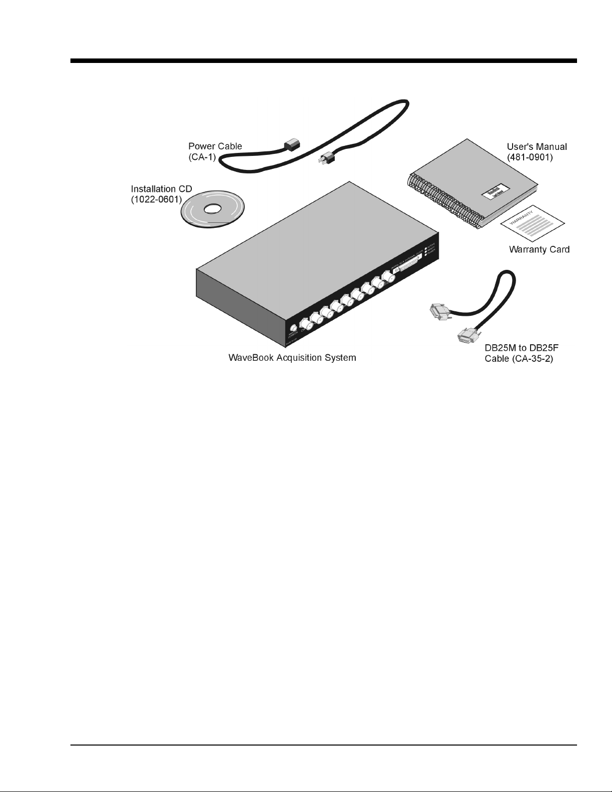
WaveBook, Basic Package
The basic WaveBook package consists of items depicted in the above figure. For reason of clarity,
packaging materials are not shown.
Your order was carefully inspected prior to shipment. When you receive your order, carefully unpack all
items from the shipping carton and check for physical signs of damage that may have occurred during
shipment. Promptly report any damage to the shipping agent and the factory. Retain all shipping materials
in case the unit needs returned.
If you ordered any accessories, for example, expansion cards or modules, check the package to ensure the
additional items are included.
Report any problems to your sales agent.
WaveBook User’ s Manual
05-15-01
Unpacking 1-1
Page 10

1-2 Unpacking
05-15-01
WaveBook User’s Manual
Page 11

An Introduction to WaveBook and Optional WBKs 2
What are WaveBooks? …… 2-1
How do the different WaveBook models compare with each other?…… 2-2
What are WBKs?…… 2-3
How do WaveBooks and WBKs interrelate? …… 2-5
How are WaveBook systems powered?…… 2-6
WaveBook Specifications …… 2-7
What are WaveBooks?
WaveBooks are high-speed portable data acquisition devices that can be used in a variety of applications,
such as testing engine strain, multi-channel acoustics, mechanical integrity, and vibration/shock/strain.
WaveBook features include:
•
Power Options: Power can be supplied from an AC-to-DC adapter, battery, DBK30A rechargeable
battery module, DBK34 or DBK34A uninterruptible power supply modules.
•
Easy Connection to Notebook or Desktop PCs.
•
Analog Input Channels: BNC connectors keep input signals isolated from the chassis and commons.
•
High-Speed Digital Inputs: 8 high-speed digital inputs (16 for WaveBook/516).
•
Digital Signal Processing (DSP): Allows you to define a channel scan-sequence and associated gains
across all channels. Also provides for real-time digital calibration on a per-sample basis.
•
Programmable Scan Sequencing: A 128-location scan sequencer allows you to program the analog
channel scan sequence, the associated unipolar/bipolar A/D range, and the input amplifier gain.
WaveBook performs 1 MHz scanning and gain switching over both its built-in and expansion channels.
•
Single, or Multi-Channel Triggering
•
Pre- and Post-Trigger Readings
In addition to the features just listed, the following apply to WaveBook/516:
•
Digital-Pattern Trigger: Trigger occurs when a Digital I/O pattern is equal too, not-equal too, greater
than, or less than a user-defined 16-bit digital pattern. This is useful when trying to capture noise,
vibrations or some other physical disturbance that occurs at a particular point in a digitally-sequenced
process, such as a relay-logic-control system. Trigger latency of the digital pattern trigger is less than
200 ns for post-trigger acquisitions.
•
Pulse Trigger: Enables triggering and the correlation of lower-speed waveforms with the occurrence of
a user-defined, high-speed pulse.
•
20 kHz Low Pass Filter: Each of the eight channels has its own low pass, anti-alias filter.
•
External Clock Input: The external clock is useful when data collection depends on rotational speed
or axial position. Note that the external clock’s input can be reset to a slower rate.
WaveBook User’ s Manual
05-22-01
An Introduction to WaveBook 2-1
Page 12

How do the different WaveBook models compare with each other?
The WaveBook series presently includes three main unit models: WaveBook/512, WaveBook/512H, and
WaveBook/516. Each provides 1 MHz sampling and supports the WBK options described shortly.
WaveBook Product Comparison*
Analog Input WaveBook/512 WaveBook/512H WaveBook/516
A/D resolution
A/D speed
Sample rate
Ranges
Unipolar (
Note 2)
12-bit 12-bit 16-bit
1 MHz 1 MHz 1 MHz
1 µs/channel 1 µs/channel 1 µs/channel
0 to +10V, 0 to +5V,
0 to +2V, 0 to +1V
0 to +10V, 0 to +4V,
0 to +2V
(Note 2)
0 to +10V, 0 to +4V,
0 to +2V
(Note 2)
Bipolar
A/D accuracy
Data packing
20-kHz low-pass filter
Analog input channels
Differential amplifiers
PGAs
Maximum capacity
FIFO depth
Total Harmonic Distortion
10Hz to 20Khz, Typical
Signal to Noise and Distortion
(SINAD)
1
1
±5V, ±2.5V, ±1V, ±0.5V
±
0.025% FS
44
optional Optional
8 DE 8 DE 8 DE
1 (shared by all 8 inputs) 1 (shared by all 8 inputs) 8 (1 per analog input)
1 (shared by all 8 inputs) 1 (shared by all 8 inputs) 1 (shared by all 8 inputs)
72 Channels 72 Channels 72 Channels
64K samples 64K samples 64K samples
-78dB -78dB -84dB
-66dB -66dB -74dB
±
10V, ±5V, ±2V, ±1V
±
0.025% FS
±10V, ±5V, ±2V, ±1V
±
0.012% FS
For 12-bit resolution only
High-Speed Digital Inputs
Digital I/O
8816
Timer Input
32-Bit Timer
None None
Trigger
Single and multi-channel
Digital Pattern
Pulse
1
For WaveBook512, t he Total Harmonic Distort i on (THD) and SINAD values shown apply to the –5 to +5 V range.
For WaveBook512H and /516, the THD and SINAD values apply to the –10 t o +10 V range.
2
Unipolar ranges do not apply to WaveBook/512H or W aveB ook/516 when a WBK11, WBK12, or WBK13 is instal l ed.
*
Specifications subject to change without notic e.
444
None None
None None
4
4
4
4
2-2 An Introduction to WaveBook
05-22-01
WaveBook User’s Manual
Page 13
What are WBKs?
You can use various modules and option cards to expand your WaveBook system. These WaveBook options are known
as WBKs.
Internally, WaveBook has room for one signal-conditioning card. Externally, you can use one or more expansion
modules.
Reference Note:
The WBK option cards and modules that follow are detailed later in this user’s manual. The information is
provided in WBK document modules that begin immediately after chapter 4. The WBK document modules
are presented in alpha-numerical order and include product specifications.
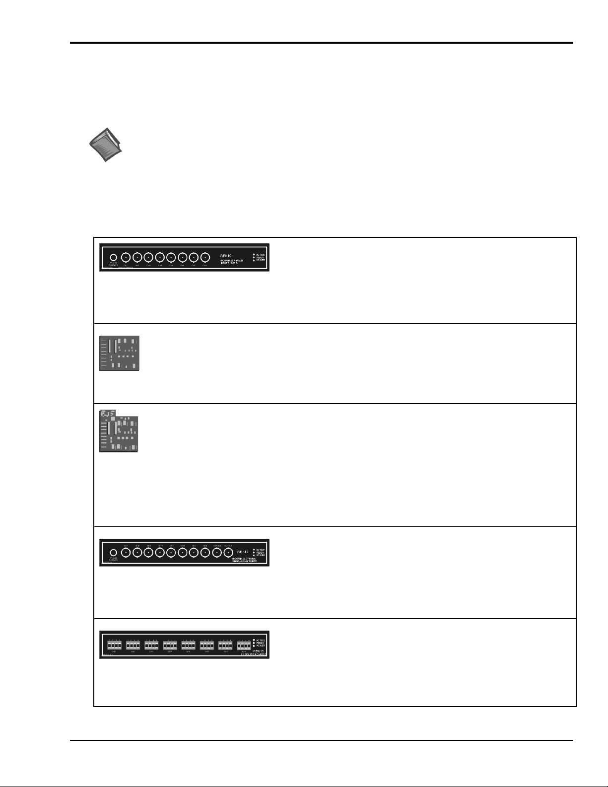
WBK Options -
Each of the following options are detailed in product-dedicated document modules.
Note that the items represented in the table are not shown to the same scale.
WBK10, WBK10H, and WBK10A
Analog Expansion Modules
8 Channels via BNC Connectors
WBK11 and WBK11A
Simultaneous Sample & Hold Card (8 channels)
WBK12 and WBK12A
Programmable Low-Pass Fil t er Card
(8 channels)
WBK13 and WBK13A
Programmable Low-Pass Fil t er Card with SSH
(8 channels)
WBK14
Dynamic Signal Conditioning Module
8 Channels via BNC Connectors
Each WBK 10 series module can be used to provi de WaveBook with
8 additional differential-analog-inputs. The modules are equipped
with a programmable gain instrumentation amplifier (PGA) and, like
the WaveBook, each has a built-in expansion bus.
Up to eight WBK 10 series modules can be c ascaded together for a
system capacity of 72 differential channels . Each module is capabl e
of supporting a WBK11, WBK 12, or WBK13 series option card.
The WBK11series cards can simultaneously sample 8 channels and
can be installed inside a WaveBook or in a WBK10 series m odul e.
The cards allow for concurrent (<150 ns) capture of multiple input
channels and virtually elim i nate channel-to-channel tim e skewing.
WBK12, WBK12A, WBK13, and WBK13A are 8-channel
programmable low-pass fil t er cards for use with W aveBook data
acquisition systems. These cards ins t al l di rectly into a WaveB ook or
WBK10 series module and provide programmabl e l ow-pass filtering
over all channels. Multiple WBK12 series and WBK13 series cards
can be installed in one syst em for up to 72 channels. Al l of the cards’
low-pass filters and cutof f frequencies are configured via s oftware.
WBK13 and WBK13A cards have the additional c apability of
sampling all channels at the same time.
The WBK14 is a dynamic analog signal input module. It enables
WaveBooks t o i nterface with piezoelectric t ransducers that include
accelerometers, microphones, and force/ pressure transducers.
Each WBK14 channel has a:
•
current source for transduc er bi asing
•
high-pass filter
•
programmable gain ampli fier
•
anti-aliasing low-pass filt er
•
simultaneous sample-and-hold (SSH) amplif i ers
WBK15
8-Slot 5B Signal Conditioning Module
8 channels via 5B Modules
WaveBook User’s Manual
The WBK15 m odul e provi des for a diverse range of signals avail abl e
through optional 5B modules. Meas urement types include: LVDT,
potentiometer, isolated current loop, ±10mV to ±40V inputs, li neari zed
RTD, thermocouple, frequency-to-voltage, and strain gage.
See latest catalog or c ont act your sales representat i ve in regard to the
types of 5B Modules av ai l abl e for your application.
05-22-01
An Introduction to WaveBook 2-3
Page 14
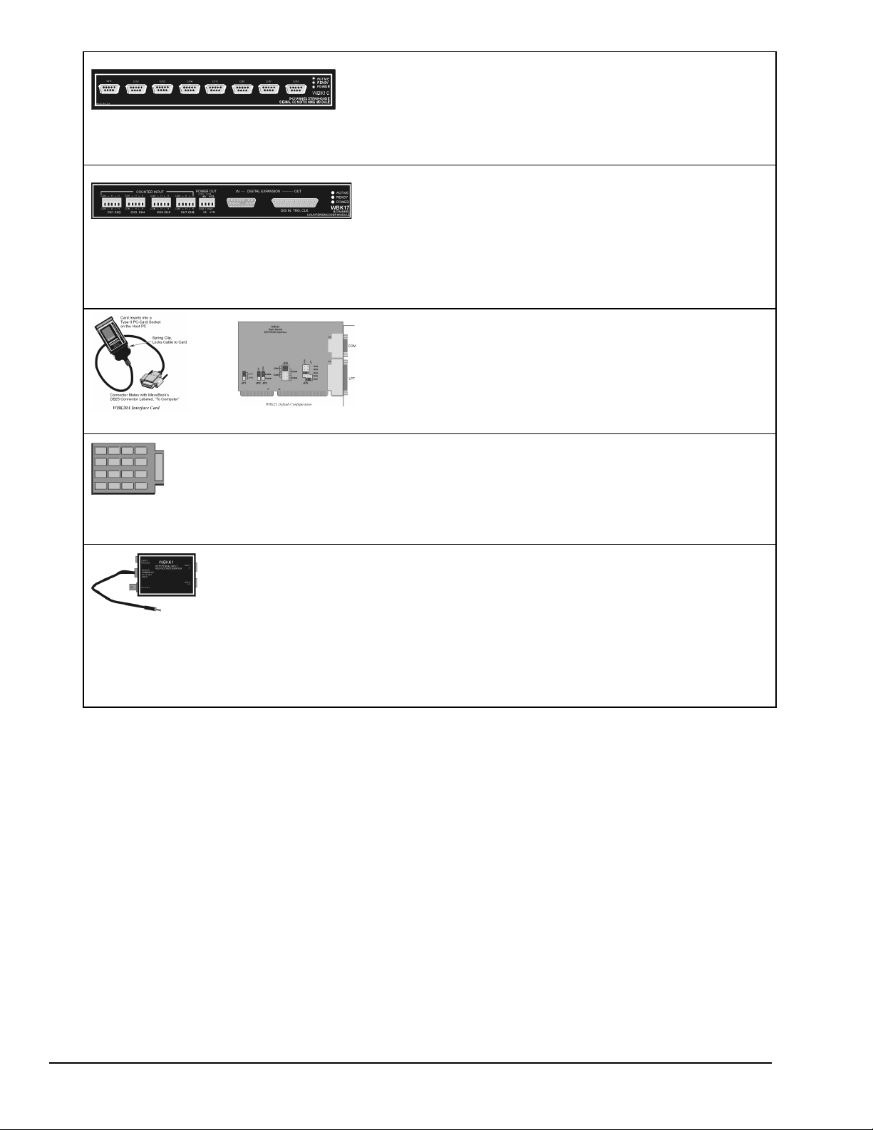
WBK16
Strain-Gage Module
8 channels via Standard Female DB9
WBK17
Used with WaveBook/516 Only
Counter-Input Module with Quadr ature Encod er
Support
8 channels via Removable Screw Terminal B l ocks
WBK20A
WBK21
WBK30
WaveBook Memory Options
WBK16 is an 8-channel strain-gage signal-condit i oni ng module. Up
to eight WBK 16 modules (64 channels) can be accommodated by
the WaveBook and s canned at 1 µs/channel. Alm ost all bridge
configurations are supported via a bri dge-completion network and
software. High-gain differential-amplifier applicati ons are also
supported. Software controls bri dge configuration, gain, offset,
excitation voltage, polarity, f i l tering, and the calibration proc ess.
The WBK17 is an 8-channel multi-functi on counter/encoder module
for use with Wavebook/ 516 systems. Eac h of the high-speed, 32-bit
counter channels can be confi gured for counter, period, pulse width,
time between edges, or encoder m odes. All channels are capable of
measuring analog inputs that are digitized by the W avebook/516.
WBK20A – PCMCIA/EPP Interface Card
(for linking W aveBook to a Notebook PC)
WBK21
– ISA/EPP Interface Plug-in Board
(For linking WaveBook to a desktop PC)
These devices are shipped with separate doc umentation and are not
detailed in this manual ; they are, however, discussed brief l y i n t he
WBK20A and WBK21 Doc ument M odul es
WBK30 is a DRAM-based memory board that ins talls inside a
WaveBook. There are t hree models of W B K30 available; each
significantly increases the capacity of WaveBook's s tandard data
buffer of 64 K samples. Capacities are as fol l ows:
WBK30/16— 16 MB
WBK30/64— 64 MB
WBK30/128— 128 MB
.
WBK61 and WBK62
WBK61
: High-Voltage Adapter with 200:1 Voltage
Divider (1 channel)
WBK62
: High-Voltage Adapter with 20:1 Voltage
Divider (1 channel)
WBK61 and WBK62 are single-channel hi gh-vol tage adapters that
can be used with the WaveB ook or WBK10/10H/ 10A expansion
modules. In addition, WBK61 and WBK62 can be used in conjunc tion
with WBK11, WBK12, and WBK13 series cards.
WBK61 and WBK62 include safety-style banana-jacks for the high
and low inputs, and 60-inch (152 cm) c abl es with probe tips and
alligator clips for eas y i nput connection.
2-4 An Introduction to WaveBook
05-22-01
WaveBook User’s Manual
Page 15
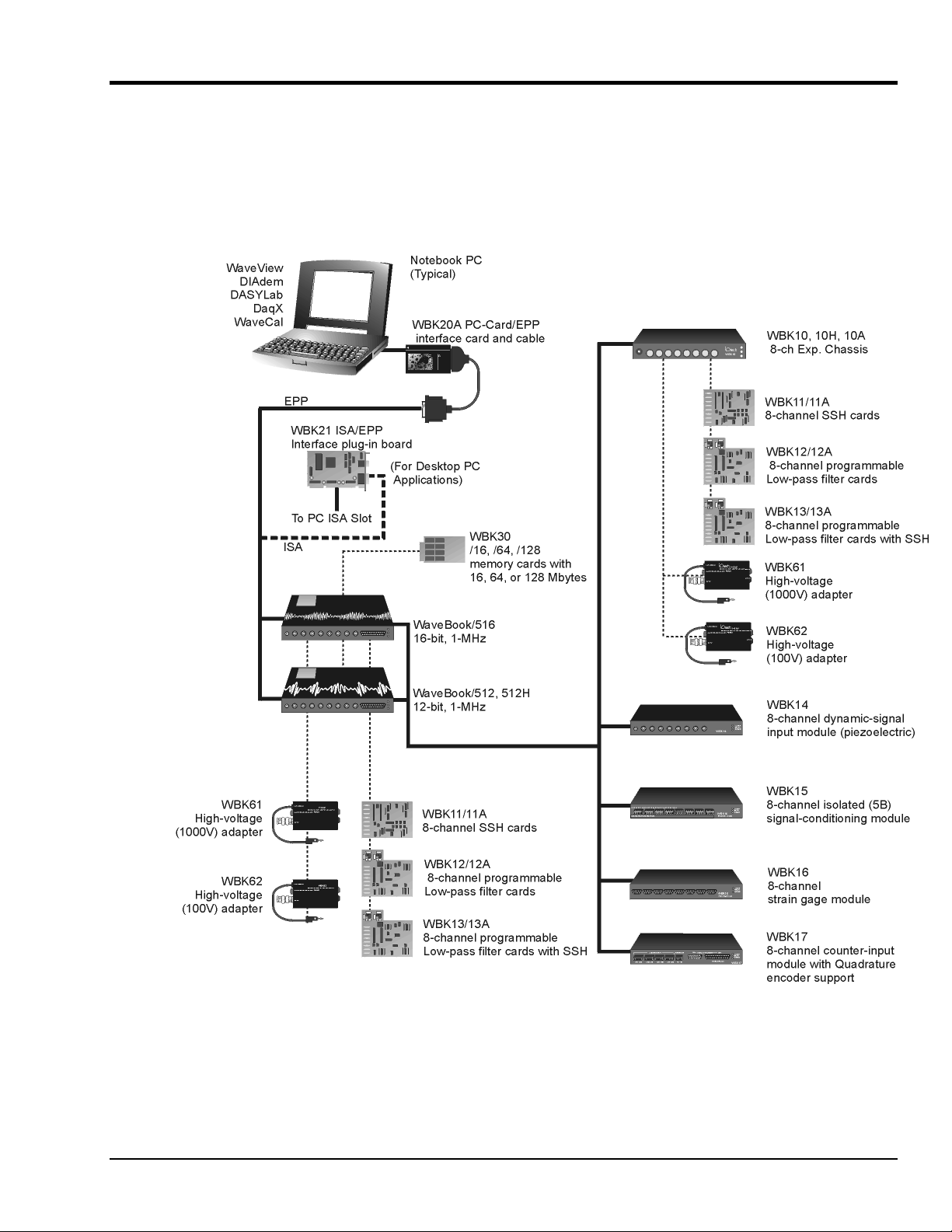
How do WaveBooks and WBKs interrelate?
WaveBooks and WBKs interrelate when they become part of the same data-acquisition system. The
relationship can be broken down into enhancement, expansion, or both. The following illustrates the
relationship of various system components. Detailed information and product specifications are provided in
WBK document modules that are included as a part of this manual.
WaveBook System Components
WaveBook User’s Manual
05-22-01
Note
: WBK17 is for use with
WaveBook/516 only.
An Introduction to WaveBook 2-5
Page 16

How are WaveBook systems powered?
Input voltage to the WaveBook and to the system modules (WBK10 series, WBK14, WBK15, WBK16,
and WBK17) must be in the range of 10 to 30 VDC and can come from an appropriate AC-to-DC adapter,
or from a battery.
Available AC-to-DC adapters include the TR-40U (supplied), which has an input of 90-264 VAC and a
output rating of 2.2 amps @ 15 VDC.
Battery options include the DBK30A, DBK34A, or other 10 to 30 VDC source such as a car battery. The
DBK30A provides 14 VDC and when fully-charged has a storage capacity of 3.4 A⋅hr; car batteries have
much higher capacities. The basic formula for battery life is:
Runtime (hr) = Battery capacity (A⋅hr) / Current load (A)
System cards (WBK11, WBK12, or WBK13 series) get power from their WaveBook or WBK10/10H/10A
expansion module.
Before connecting your system to power, you need to know the power requirements of your specific system.
A calculation method, that incorporates the use of worktables, is presented in Chapter 3.
Reference Notes:
•
Chapter 3, System Setup and Power Options, includes examples of power connections for
different WaveBook system scenarios. In these examples the included TR-40U power
adapters are used.
•
Chapter 4, WaveBook Operation Reference, includes discussion of power supplies other
than the TR-40U.
2-6 An Introduction to WaveBook
05-22-01
WaveBook User’s Manual
Page 17

WaveBook Specifications – Product Comparison
WaveBook Product Comparison
Features WaveBook/512 WaveBook/512H WaveBook/516*
Analog Input
A/D resolution
A/D speed
Sample rate
Ranges
Unipolar
12-bit 12-bit 16-bit
1 MHz 1 MHz 1 MHz
1 µs/channel 1 µs/channel 1 µs/channel
0 to +10V, 0 to +5V,
0 to +10V, 0 to +4V,
0 to +2V, 0 to +1V
0 to +2V
0 to +10V, 0 to +4V,
0 to +2V
Bipolar
A/D accuracy
Data packing
20-kHz low-pass filter
Analog input channels
Differential amplifiers
PGAs
Maximum capacity
FIFO depth
Total Harmonic Distortion
10Hz to 20Khz, Typical
Signal to Noise and
Distortion (SINAD)
1
±5V, ±2.5V, ±1V, ±0.5V
±
0.025% FS
44
optional optional
8 DE 8 DE 8 DE
1 (shared by all 8 inputs) 1 (shared by all 8 inputs) 8 (1 per analog input)
1 (shared by all 8 inputs) 1 (shared by all 8 inputs) 8 (1 per analog input)
72 Channels 72 Channels 72 Channels
64K samples 64K samples 64K samples
1
-78dB -78dB -84dB
-66dB -66dB -74dB
±
10V, ±5V, ±2V, ±1V
±
0.025% FS
±10V, ±5V, ±2V, ±1V
±
0.012% FS
For 12-bit resolution only
High-Speed Digital Inputs
Digital I/O
8816
Counter Input
32-Bit Counter
None None
Trigger
Single and multi-channel
Digital Pattern
Pulse Trigger
1
For WaveBook512, t he Total Harmonic Distort i on (THD) and SINAD values shown apply to the –5 to +5 V range.
444
None None
None None
For WaveBook512H and /516, the THD and SINAD values apply to the –10 t o +10 V range.
4
4
4
4
Note: Specifications are subject to change without notice.
WaveBook User’s Manual
05-22-01
An Introduction to WaveBook 2-7
Page 18

WaveBook/512 and WaveBook/512H – Specifications*
WaveBook/512 and WaveBook/512H Specifications*
General
Power Consumption
Input Power Range
Operating Temperature
Storage Temperature
Humidity
Dimensions
Weight
Fuse
Analog Inputs
Channels
Connector
Resolution
Maximum Overvoltage
Input Current
Input Impedance
Accuracy
Offset
Triggering
Single-Channel Analog Trigger
: 0 to 95% RH, non-condensing
(8.5" × 11" × 1.375”)
Single-ended:
Differential:
Range
Latency
: 216 mm wide × 279 mm l ong × 35 mm high
: 1.5 kg (3.3 lb)
: user-replaceable 4-A Littel f use # 251004
: 8 differential, expandable up to 72 diff erential
: BNC
: 12 bit
: ±0.025% FS
: ±1 LSB max
: -5 to +10 VDC
: 300 ns
: 0.9A max @ 15 VDC
: 10 to 30 VDC
: 0 to 50°C
: 0 to 70°C
: ±30 VDC
: 50 nA typ, 500 nA max
:
5 MΩ in parallel with 30 pF
10 MΩ in parallel with 30 pF
:
Multi-Channel Analog Trigger (up to 72 channels)
TTL Trigge r
Software Trigger
Latency
Sequencer
Programmable for channel , gain & for unipolar/bipolar range
Depth
Channel to Channel Rate
Maximum Repeat Rate
Minimum Repeat Rate
Expansion Channel Sample Rate
High-Speed Digital Inputs / General-Purpose Outputs
I/O Lines
Connector
Sampling
Input Low Voltage
Input High Voltage
Input Low Current
Input High Current:
: Selectable per channel to i nput range
Range
: 2 µs/channel, plus 4µs (max)
Latency
Range
Latency
in random order
channels, 1 µs/ channel
:
: TTL-compatible
: 200 ns
:
: 100 µs typ
: 128 location
: 8, WaveBook /512
: DB25 female
: Sampled with analog data
:
: 1 µs/channel, fixed
: 1 MHz
: 100 seconds per scan
: Same as onboard
: 0.8 V max
: 2 V min
: 500 µA
300 µA
WaveBook/516 specifications are presented separately, in a new format beginning on the following page
*
Note:
Specifications are subject to change without notice.
.
2-8 An Introduction to WaveBook
05-22-01
WaveBook User’s Manual
Page 19

Wavebook/516 and WBK10A Specifications
Analog Specifications
(Either WaveBook/516 stand alone or WBK10A with WaveBook/516):
Channels:
Input Connector:
8 differential, expandable up to 72 different i al
BNC, center conductor is Channel Hi, outer conductor is Channel Low
Input Voltage Ranges (DC Specifications):
Standard Unit With WBK11A
Voltage
Range
0 to +10V .012% .008% 2 .012% .008% 2 .012% .008% 2.2 2.2
0 to +5V (10A)
0 to +4V (516)
0 to +2V .012% .012% 3 .012% .012% 3 .012% .012% 2.2 3
0 to +1V
(10A only)
0 to +.5V .018% .033% 6 .018% .033% 2.2 6
0 to +.2V .018% .08% 8 .018% .08% 2.2 12
0 to +.1V .018% .16% 15 .018% .16% 2.2 20
-10 to +10V .012% .008% 2 .012% .008% 2 .012% .008% 2.2 2.2
-5 to +5V .012% .008% 2 .012% .008% 2 .012% .008% 2.2 2.2
-2 to +2V .012% .009% 2 .012% .009% 2 .012% .009% 2.2 3
-1 to +1V .018% .012% 3 .018% .012% 3 .018% .012% 2.2 3.3
-.5 to +.5V
(10A only)
-.2 to +.2V .018% .033% 8 .018% .033% 2.2 12
-.1 to +.1V .018% .08% 15 .018% .08% 2.2 20
-.05 to +.05V
(10A only)
Notes: 1. Specifications assume differential input scan, unf i l tered.
2. Accuracy specif i cation is exclusive of noise.
3. Unipolar ranges unavailable for 516 with WBK11A, 12A, or 13A options installed. Avail abl e with WBK10A and any option.
Accuracy
One Year, 18-28
±
reading
.012% .009% 2 .012% .009% 2 .012% .009% 2.2 2.2
.012% .018% 3 .012% .018% 3 .012% .018% 2.2 3
.018% .018% 5 .018% .018% 6 .018% .018% 2.2 6
(Note 2)
%
±
range
°C
%
Input Noise
LSB rms
DC-500KHz
(typical)
Accuracy
One Year, 18-28
±
reading
.018% .16% 26 .018% .16% 440
(Note 2)
%
±
range
(Note 3)
Input Noise
LSB rms
DC-500KHz
°C
%
(typical)
With WBK12A/13A
Accuracy
One Year, 18-28
±
reading
(Note 2)
%
±
range
°C
1KHz
%
Filter
(Note 3)
Input Noise
LSB rms
(typical)
Filter
Bypass
System Performance:
Differential Nonlinearity:
Total Harmonic Distortion (10Hz-20KHz):
Signal to Noise and Distortion (SINAD, 10Hz-20KHz):
Temperature Coefficient of Accuracy (0-18 and 28-50°C):
Input Resistance:
Bias Current:
Common Mode Rejection:
Input Bandwidth:
Hostile Channel-to-channel Crosstalk (5Vrms input signal , DC-100KHz):
Over-Voltage Protection:
one year, 18-28°C unless otherwise noted
With PGA and WBK11A:
With WBK12A/13A:
5MΩ (single ended); 10MΩ (differential), in parallel with 30pF
<400 nA (0 to 35°C)
DC to 500KHz
Note: Specifications are subject to change without notice.
WaveBook User’s Manual
±2 LSB max
-84dB typical
-74dB typical
± (.002% + 0.6 LSB)/°C typical, -10 to +10V range
± (.002% + 1 LSB)/°C typical, -10 to +10V range
>70dB minimum ; >80dB typical; DC-20KHz
±35 V relative to analog common
05-22-01
-88dB typical
An Introduction to WaveBook 2-9
Page 20

PGA Filter
WBK11A Functions
WBK12A/13A Functions
Triggering
Filter Type:
Input Voltage Ranges:
Aperture Uncertainty (SSH):
Voltage Droop (SSH):
Input Voltage Ranges:
Low Pass Filter Type:
Anti-Aliasing Filters:
Low-Pass Filter Frequency Cutoff Range:
Filter Grouping:
Aperture Uncertainty (SSH):
Voltage Droop (SSH):
Channel 1 Analog Trigger
Input Signal Range:
Input Characteristics and Protection:
Latency:
Multi-Channel Analog Trigger (up to 72 channels):
Range:
Latency:
20KHz low pass, Butterworth, 5-pole fi l ter
Software programmable prior to a s can sequence
75ps max
0.01mV/ms typ
Software programmable prior to a s can sequence
Software selectable, 8-Pole elliptic or linear phase
Single-pole pre and post filters, automatically set depending on filter frequency se l ected
4 Channels each in two programmable bank s
75ps max
0.01mV/ms typ
-10 to +10V
Same as channel inputs
300ns
Selectable per channel to input range
2us/channel, plus 4us maximum
100KHz, 75KHz, 60KHz…400Hz, bypass (fc=300KHz/N where N=3 to 750
TTL Trigge r:
Input Signal Range:
Input Characteristics:
Input Protection:
Latency:
Software Trigger
Latency:
Pulse Trigger
Input Signal Range:
Input Characteristics:
Input Protection:
Minimum Pulse Width:
Latency:
External Clock
Connector:
Input Signal Range:
Input Characteristics:
Input Protection:
Delay: 200ns
Signal Slew Rate Requirement:
Rate:
Divisor ratio:
Clock Counter Accuracy:
Clock Counter Range:
0-5V
TTL-compatible with 10K ohm pul l -up res i stor
Zener clamped –0.7 to +5V
300ns
100us typical
0-5V
75 ohms
±
10V maximum
100ns
300ns
Available on DB25 digital input
5V TTL compatible
50K ohms pull up (to +5V) in parall el with 50pF
Zener clamped –0.7 to +5V
Up to 1MHz
Divide by 1 through 255, selectable
<0.02% error
0.01Hz to 100KHz
20V/us minim um
2-10 An Introduction to WaveBook
05-22-01
WaveBook User’s Manual
Page 21

Sequencer
Operation:
Depth:
Channel-to-Channel Rate:
Maximum Repeat Rate:
Minimum Repeat Rate:
Expansion Channel Sample Rate:
Programmable for channel , gai n, and for unipolar/bipolar range in random order
128 location
1.0-1.1us/channel, all channels equal
1MHz
100 seconds per scan
Same as on-board channels
High-Speed Digital Inputs/General-Purpose Outputs
Connector:
Configuration:
Input Characteristics:
Output Characteristics:
Output Updates:
Input/Output Protection:
DB25 Female
16 TTL-compatible pins, selectable for input or output
TTL-compatible
ALS TTL output in series with 33 ohm s
Outputs may be changed via program control
Diode clamped to ground and +5V
General Specifications
Warm-up:
Environment:
Power Consumption:
Input Power Range:
Vibration:
Dimensions:
Weight:
30 minutes to rated specifications
Operating:
Storage:
MIL Std 810E, Category 1 and 10
220 deep X 285 wide X 45 mm high (8.5 X 11 X 1.75 inches)
1.5kg (3.3 lbs)
0-50°C, 0-95% RH (non-condensing)
-20 to 70°C
1.4A max @ 15VDC (WBK10A or 516 with WBK13A i nstalled)
10-30VDC
Included Accessories and Software
Software:
Hardware:
WaveView
DIAdem View
DOS and Windows Drivers
WaveCal
AC Adapter
Parallel Cable
Users Manual
Optional Accessories
Software:
Hardware:
DasyLab
LabView Driver
HA-111 Fastener-Panel Handle
CA-115 5-pin male DIN to 5-pin male DIN
CA-116 5-pin DIN to automobile cigarett e l i ghter power cable, 8 ft
CA-178 DB25 to external cloc k BNC
CA-150-1 Single Male BNC to Male BNC CE Compliant cable
CA-150-8 Eight Male BNC to Mal e B NC CE Compliant cables
WaveBook User’s Manual
05-22-01
An Introduction to WaveBook 2-11
Page 22

2-12 An Introduction to WaveBook
05-22-01
WaveBook User’s Manual
Page 23
System Setup and Power Options 3
A
C
Introduction …… 3-1
Connecting a WaveBook to a PC …… 3-1
PC Requirements…… 3-1
Connecting the Communication Cable…… 3-2
System Enhancement and Expansion …… 3-2
Adding WBK Option Cards …… 3-2
Adding WBK Modules…… 3-4
Module Options……3-4
Connectors and Cables ……3-5
Example of a WaveBook System Daisy-Chain …… 3-7
How Channel Numbers are Determined ……3-7
Stacking Modules …… 3-8
Connecting Encoders to WB K 17…… 3-8
Connecting the System to Power ……3-9
Calculating the System Power Requirement…… 3-9
Three System Examples …… 3-11
Power Supplies …… 3-13
Installing Software……3-21
Using the Daq Configuration Applet to Check Connections…… 3-21
An incorrect use of power can damage equipment or degrade performance. Prior to
connecting your devices to power, calculate your system’s power requirements.
Introduction
This chapter pertains to setting up a WaveBook system. Topics include how to: connect a WaveBook to a
PC, add option cards and modules, properly power a system, install software, and check connections with
the Daq Configuration Applet. As stated in the above Caution, you will need to calculate system power
requirements prior to powering the system.
Connecting a WaveBook to a PC
PC Requirements
Notebook PCs are typically used to communicate with WaveBook
acquisition hardware. However, desktop PCs can be used.
Regardless of your PC preference, the following requirements apply:
•
16MB Ram (32 MB Ram recommended)
•
Pentium
•
10 MB of Available Disk Space
•
Windows Operating System
(Windows95/98/Me, or WindowsNT/2000)
•
Optional, but recommended:
EPP (Enhanced Parallel Port), or
ECP (Extended Capabilities Port)
®
90 Processor (or equivalent)
&$87,21
Notebook PC is Typically Used to
ommunicate with WaveBook
WaveBook User’ s Manual
05-15-01
System Setup and Power Options 3-1
Page 24
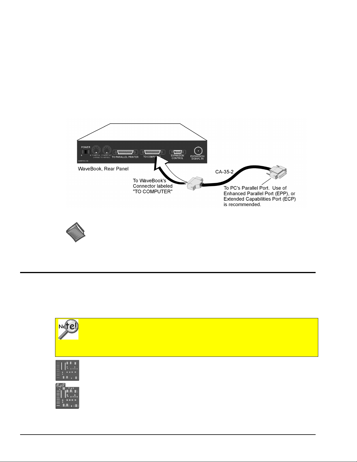
Connecting the Communication Cable
WaveBook communicates with a notebook or desktop PC through the computer’s parallel port. Use of an
Enhanced Parallel Port (EPP) or an Extended Capabilities P ort (ECP) is recommended.
Two card options are available for use with PCs that do not have Enhanced Parallel Ports. These are:
•
WBK20A PCMCIA/EPP interface-card, to be used in conjunction with
a notebook’s PC-Card port.
•
WBK21 ISA/EPP interface-card, for use with a desktop PC.
Both options are discussed in the WBK20A and WBK21 Document Module (included as a part of this
manual) and are shipped with additional documentation.
The CA-35-2 communication cable connects to the host PC through a 25 -pin connector , located o n
WaveBook’s rear panel. The WaveBook connector is labeled “TO COMPUTER.”
Connecting the Communication Cable (CA-35-2)
Reference Note:
For information regarding the optional WBK20A PCMCIA/EPP interface-card, or the
WBK21 ISA/EPP interface-card, refer to the documentation that is shipped with those
products. WBK20A connects to the notebook’s PC-Card port. WBK21 connects to a
desktop PC’s ISA slot. Both options are discussed briefly in the WBK20A and WBK21
Document Module.
System Enhancement and Expansion
Adding WBK Option Cards
This section pertains to adding a WBK11, WBK12, or WBK13 Series card to a WaveBook/512 or to a
WBK10, or WBK10H expansion module.
Important Notice Regarding the WaveBook/516 and the WBK10A
Cards for WaveBook/516 and WBK10A are installed at the factory per customer order.
Users are not to remove or install cards for these two products as the applicable cards are
not “plug-and-play” for these devices and erroneous signal values could result. If you
desire to remove or add a card to these products, contact your service representative.
WBK11, WBK11A
Simultaneous Sample & Hold Cards (8 channels each)
:
WBK12, WBK12A, WBK13, and WBK13A
WBK12, WBK12A: Programmable Low-Pass Filter Cards (8 channels each)
WBK13, WBK13A: Programmable Low-Pass Filter Card with SS H (8 c hannel s each)
All WBK11, WBK12,WBK13, and WBK11A, WBK12A, and WBK13A configurations are controlled by
software. There are no hardware settings.
3-2 System Setup and Power Options
05-15-01
WaveBook User’s Manual
Page 25
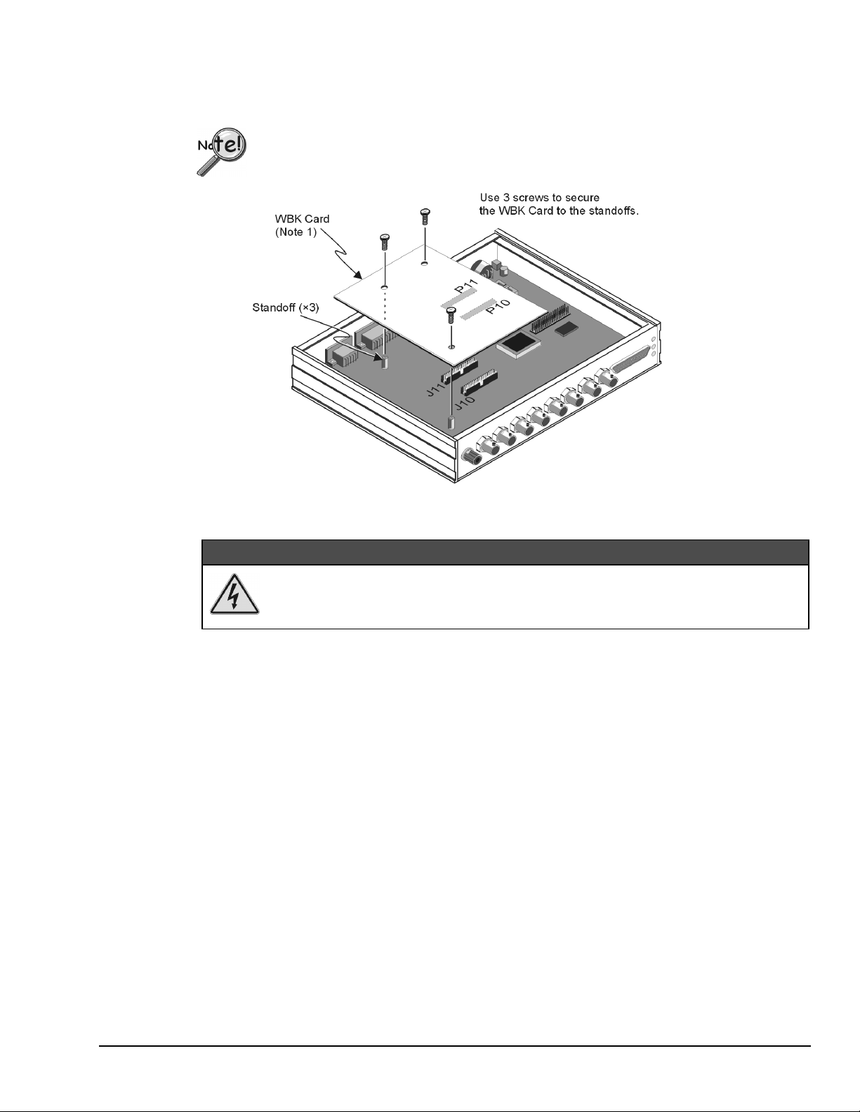
The WBK Card connects to headers J10 and J11 in the base unit. The base unit can be a WaveBook/512,
WaveBook/512H, WBK10 or WBK10H. The jumpers located on J10 and J11 provide signal pass-through
when a WBK option card is not installed. Refer to the following figure and steps to install an option card
into a WaveBook/512, WBK10, or WBK10H module.
Although the figure represents installation of a WBK11 into a WaveBook/512, the method
used to install other WBK options into a WaveBook, WBK10, or WBK10H is the same.
Installing a WBK Option Card
:$51,1*
Electric shock hazard! Remove the WaveBook, and all devices connected to it, from
power before removing the cover plate. Failure to do so could result in electric shock
and possible death.
1. Remove all power from the unit and any connected devices.
2. For WaveBook/512 series, WBK10, or WBK10H, remove the screw holding down the top panel
(cover), and slide the panel out towards the back (see following figure).
For WaveBook/516 and WBK10A, contact the factory in regard to adding or replacing option
cards.
3. Remove the stand-off screws, then remove old WBK card from J10 and J11.
If no card was present, skip to step 4.
4. Locate the headers J10 & J11 on the main board, and remove the jumpers (if present).
Save the jumpers in the event the SSH board needs to be removed.
5. Align the WBK card headers (P11 & P10) with the host board headers (J11 & J10), respectively.
6. Verify alignment of the board. An easy way is to check that the board’s screw holes are in line with the
standoffs.
7. Carefully push the WBK option card do wn until the connectors fully mate.
8. Using three screws, secure the WBK card to the standoffs. Do not over-tighten.
9. Slide the top panel onto the unit, and secure it using the top panel screw.
WaveBook User’s Manual
05-15-01
System Setup and Power Options 3-3
Page 26

Adding WBK Modules
Module Options
Several WBK module options are currently available for use with WaveBook systems. This section is
concerned with “how the modules are connected and powered.” Functions, specs, and software issues are
discussed elsewhere.
Note that each of the following module options offers 8 channels.
WBK10, WBK10H, & WBK10A
Expansion Modules
WBK14
Dynamic Signal Conditioni ng Module
WBK15
8-Slot 5B Signal Conditioning Module
WBK16
Strain-Gage Module
WBK17
Counter-Input Module with Quadrature Encoder Support;
Used with WaveBook/516 only.
Modules Currently Available for WaveBook System Expansion
Connection basics are the same, regardless of whether the WaveBook system has one module or eight
modules. Examples of various setups follow shortly.
Power requirements can vary greatly from one WaveBook system to another, and will need to be calculated
on a system by system basis, before power is applied to the system. This chapter includes instructions for
calculating power requirements.
Before discussing how to calculate power, we will look at the use of connectors and the types of cables
used.
3-4 System Setup and Power Options
05-15-01
WaveBook User’s Manual
Page 27

Connectors and Cables
To attach a module, connections must be made for power, expansion control, and expansion signals. The
following connectors and cables are used.
•
WaveBook POWER IN – connects to a 10 to 30 VDC source.
•
WaveBook POWER OUT – can be connected to the first module’s POWER IN.
•
WaveBook EXPANSION CONTROL – connects to the first module’s
EXPANSION CONTROL IN.
•
WaveBook EXPANSION SIGNAL IN – connects to the first module’s
EXPANSION SIGNAL OUT.
•
WBK POWER IN – connects to a 10 to 30 VDC source. When in a power daisy-chain,
POWER IN connects to the previous WaveBook or WBK module’s POWER OUT.
•
WBK module POWER OUT – can be connected to the next module’s POWER IN, providing the
5 amp current limit will not be exceeded. It may be necessary to use a supplemental power supply.
Power requirements and discussed in the following pages.
•
WBK module EXPANSION CONTROL OUT – connects to the next module’s
EXPANSION CONTROL IN.
•
WBK module EXPANSION SIGNAL IN – connects to the next module’s
EXPANSION SIGNAL OUT.
Prior to connecting your devices to power, calculate your system’s power requirements as
discussed in upcoming section of this chapter. Note that three examples of system setups
follow shortly.
Using Shielded BNC Connectors for CE Compliance
Certain Declarations of Conformity identify specific cables and connectors that must be used to
meet CE requirements. CE compliant BNC-equipped cards and modules have BNC connectors
that are insulated from high voltage sources, including electrostatic discharges (ESD). Such
voltages could enter the circuitry through the exposed conductive surface of a connector,
possibly resulting in damage to components.
O-Ring
S hielded
BNC Connector
Dust Cap
Shielded BNC Connector (with O-Ring) and PVC Dust Cap
To meet CE requi rements, PVC dust caps (p/n CN-96) must cove r all unused BNC connectors.
When dust caps are not in place, special coaxial cables (with insulated end-connectors and
rubber O-rings) must be used. Note that part number 418-0800 includes two cables (with
shielded BNC connectors at each end), and four insulating O-rings.
Properly installed connectors and dust caps ensure the metallic surfaces of the connectors are
not exposed to undesirable electrical charges.
WaveBook User’s Manual
05-15-01
System Setup and Power Options 3-5
Page 28

CA-115 Power Cables. CA-115 cables are 6 inches long and have two 5-pin male DIN
connectors. CA-115s are frequently used to link WaveBook’s POWER OUT connector to a WBK
expansion module’s POWER IN connector. CA-115 cables are also used to link an expansion
module’s POWER OUT connector to the next daisy-chained module’s POWER IN connector.
CA-115 cables and the device DIN5 connectors (see following figure) are limited to 5 amps
at 15 VDC.
Power is supplied to WaveBook modules via a DIN5
type connector located on the rear panel of the device.
+10 to +30 V 4
+10 to +30 V 1
Return
2
5 No conn ection
3 Retu rn
*The DIN5 pinout [to the left] is based on an external
DIN 5 Power Pinout*
view of a WaveBook rear panel.
Note: An optional CA-116 power cable is available. The CA-116 permits the system to be plugged into
a vehicle cigarette lighter, allowing use of the vehicl e’s battery as a power supply for the
WaveBook device.
CA-129 Expansion Control Cables. Control messages are carried by CA-129 expansion-control
cables with HD-15, plug and socket connectors. The first expansion unit’s control input is driven
from the main unit’s control output. Control inputs of additional WBK modules are driven from
the preceding unit’s control output.
CA-150 Expansion Signal Cables. Expansion signals are carried by a CA-150-1 male BNC to
male BNC coaxial cable. Each WBK module drives a common parallel analog bus that carries the
signals to WaveBook’s Analog-to-Digital Converter (ADC). Each WBK module has
EXPANSION SIGNAL IN and EXPANSION SIGNAL OUT connectors for daisy-chaining
multiple units.
Calculate system amp load prior to creating a system daisy-chain. Although WaveBook
device connectors and CA-115 power cables have 5 amp limits, TR-40Us are limited to
2.2 amps. Tables for determining amp load are provided in the following section,
Calculating System Power.
CA-177 Strain Gage Cablse. CA-177 is an optional set of eight strain-gage cables intended for
use with the eight channels of WBK16. Discussions of the CA-177 strain-gage cable and bridge
applications are contained in the WBK16 document module.
3-6 System Setup and Power Options
05-15-01
WaveBook User’s Manual
Page 29

Example of a WaveBook System Daisy-Chain
How Channel Numbers are Determined
The analog input channel numbers are determined by the order of
connection among the WaveBook and attached WBK modules.
•
Channel 0 is the WaveBook’s 8-bit digital I/O port.
•
Channels 1 through 8 are the Wave Book’s main channels.
•
Channels 9 through 16 are loc ated on the fir st expansion unit
connected directly to the WaveBook.
•
Additional channel numbers are added consecutively (in groups
of 8) with each added WBK module (see table at right).
* WBK in the “Unit” column refers to a module such as a WBK10,
WBK14, WBK15, WBK16, WBK17.
Unit* Channel #
WaveBook 0 (dig I/O)
WaveBook 1-8
1st WBK 9-16
2nd WBK 17-24
3rd WBK 25-32
4th WBK 33-40
5th WBK 41-48
6th WBK 49-56
7th WBK 57-64
8th WBK 65-72
WaveBook User’s Manual
05-15-01
System Setup and Power Options 3-7
Page 30

Stacking Modules
Using Splice Plates to Stack a WaveBook and two WBK Modules (the handle is optional)
WBK modules are typically shipped with a splice plate kit. Each kit includes two metal plates that screw
onto the sides of stacked modules. The plates provide a means of stacking modules to create one rigid
assembly. Optional handles can be attached to the splice plates.
Note:
Splice plates will partially block the vents on WBK16s and WaveBook/516s when stacked.
This partial blocking of vents does not jeopardize the cooling process.
Connecting Encoders to WBK17
Encoders can be used in a WaveBook system, providing the system contains at least one WBK17 module.
For information regarding encoders and the necessary connections, refer to the WBK17 Document Module.
3-8 System Setup and Power Options
05-15-01
WaveBook User’s Manual
Page 31

Connecting the System to Power
Calculating the System Power Requirement
An incorrect use of power can damage equipment or degrade performance. Prior to
connecting your devices to power, calculate your system’s power requirements.
Do not daisy-chain the power connections of more than three WBK10 series module
units. Daisy-chaining a power connection to a fourth module will exceed the power
connector’s 5 amp current limit.
It is important to supply your system with adequate, reliable power. For this reason, you need to know your
system’s power requirement. Computing power use is also important when using batteries to power
modules, as you will need to know a safe runtime before recharging is required.
&$87,21
&$87,21
s
The following statements relate to system power. They should be reviewed before
proceeding.
•
Higher voltages draw fewer Amps for the same power.
Remember: Watts = voltage x current (W = E*I).
•
The TR-40U power adapter provides power that is sufficient for the WaveBooks
and WaveBook modules. You do not need to make power requirement calculations
unless you intend daisy-chaining units, or yo u ha ve a critical battery runtime.
•
Do not overload your power supplies. TR-40U power adapters are limited to
2.2 amps. However, you can use more than one TR-40U, as indicated in one of the
upcoming daisy-chain examples.
•
Current drawn from other sources, such as car batteries, can be estimated from the
following WaveBook Product Current Requirements table.
Use the current requirements and worksheet tables to calculate your system’s total power requirement.
Take the appropriate amperage values from the first table to fill in the second table; then perform the
indicated multiplication and addition operations to calculate the amperage for all units in your system.
WaveBook User’s Manual
05-15-01
System Setup and Power Options 3-9
Page 32

WaveBook Product Current Requirements (in Amps)
Products and
Product Combinations
WaveBook/512 (alone)
WaveBook/512H (alone)
WaveBook/516 (alone)
WBK10 (alone)
WBK10H (alone)
WBK10A (alone)
WBK11, WBK11A
WBK12, WBK12A
WBK13, WBK13A
WBK14 (alone)
WBK15 (alone)
WBK15 (typical)
WBK15 (max)
WBK16 (no excitation)
WBK16 (full excitation)
WBK16/SSH
WBK17 (alone)
WBK17 with 1 encoder
WBK17 with 2 encoders
WBK17 with 3 encoders
WBK17 with 4 encoders
WBK30
Note 1: Typical with 8 voltage modul es.
Note 2: Maximum load with 8 strain-gage modules. You may need to consult power specificati ons for
individual 5B modules and fo r any excit ation currents required.
Note 3: Assumes 0.500 W per encoder.
Product Qty
WaveBook/512/512H
WaveBook/516
WBK10/10H
WBK10A
WBK11
WBK12
WBK13
WBK14
WBK15
WBK16
WBK17
Note 1
Note 2
Note 3
Note 3
Note 3
Note 3
Worksheet for Power Requirements
DBK30A
14 VDC
0.43 0.20 0.52 0.23 0.40
0.40 0.20 0.48 0.23 0.40
1.00 0.50 1.20 0.60 1.00
0.32 0.20 0.38 0.19 0.30
0.33 0.22 0.40 0.26 0.33
0.35 0.17 0.42 0.20 0.35
0.27 0.10 0.32 0.16 0.22
0.47 0.23 0.56 0.27 0.45
0.57 0.28 0.68 0.33 0.50
0.90 0.50 1.08 0.53 0.85
0.13 0.08 0.16 0.09 0.12
0.24 0.13 0.29 0.15 0.23
0.75 0.36 0.90 0.44 0.75
1.08 0.52 1.30 0.61 1.00
1.80 0.87 2.10 1.00 1.67
1.20 .60 1.44 0.70 1.20
0.52 0.31 0.62 0.36 0.52
0.56 0.33 0.67 0.38 0.56
0.61 0.35 0.73 0.41 0.61
0.65 0.38 0.78 0.44 0.65
0.70 0.40 0.84 0.47 0.70
0.01 0.005 0.01 0.006 0.01
×
Amps
× =
× =
× =
× =
× =
× =
× =
× =
× =
× =
× =
DBK30A
28 VDC
Maximum
Amps
DBK34A
12 VDC
=
Totals
DBK34A
24 VDC
TR-40U
15 VDC
It is important to supply your system with adequate, reliable power. For this reason, you need to know your
system’s power requirement. Knowing the power requirement is also important when using batteries to
power modules, as you should know a safe runtime, i.e., how long you can run the system be fore recharging
is required.
Input voltage to the WaveBook/512, WaveBook/516 and to the system modules (WBK10 series, WBK14,
WBK15, WBK16, and WBK17) must be in the range of 10 to 30 VDC and can come from an AC-to-DC
adapter or from another source, such as a battery. System cards (WBK11, WBK12, or WBK13) get power
from their host WaveBook or WBK10 series expansion module.
Available AC-to-DC adapters include the TR-40U (supplied), which has an input of 90-264 VAC and an
output of 2.2 amps @ 15 VDC.
3-10 System Setup and Power Options
05-15-01
WaveBook User’s Manual
Page 33

Battery options include the DBK30A, DBK34A, and other 10 to 30 VDC sources, such as car batteries. The
DBK30A provides 14 VDC and when fully-charged has a storage capacity of 3.4 A⋅hr; car batteries have
much higher capacities. The basic formula for battery life is:
Runtime (hr) = Battery capacity (A⋅hr) / Current load (A)
Battery life and performance depend on various factors including battery type, condition, charge
level, and ambient temperature. Be sure you consider these factors, especially when runtime is a
critical.
Three System Examples
WaveBook User’s Manual
Reference Note:
Although the preceding three examples make use of one or more TR-40U power adapters,
other power sources can be used. These options are discussed in the following section,
Power Supplies.
05-15-01
System Setup and Power Options 3-11
Page 34

Reference Note:
Although the preceding three examples make use of one or more TR-40U power adapters,
other power sources can be used. These options are discussed in the following section,
Power Supplies.
Reference Note:
For information regarding encoder connections, refer to the WBK17 Document Module.
3-12 System Setup and Power Options
05-15-01
WaveBook User’s Manual
Page 35

Power Supplies
The power supplies that can be used with WaveBook setups are listed in the following table.
Item Name/Description Capacity
TR-40U
DBK30A
DBK34A
Other
DBK30A - Rechargeable Battery Module
DBK30A contains two rechargeable nickel-cadmium batteries for use with WaveBook, expansion WBK
modules, and transducers. DBK30A shares the same base dimensions as other WaveBook products,
allowing for convenient stacking. Note that stacking can be easily accomplished with the included splice
plates.
AC Power Adapter (shipped with WaveB ooks & WBK Modules) 90-264 VAC input;
Rechargeable Battery/Excitat i on Module (opt i onal ) 12-14 VDC, or 24-28 VDC
UPS (Uninterruptable Power Supply)/Bat tery Module (optional) 12 V DC, or 24 VDC
10 to 30 VCD source, such as a vehicle battery. Depends on source
DBK30A Front Panel
WaveBook Product Power Supplies
2.2 A @ 15 VDC
3.4 A-hr @ 14 VDC
5.0 A-hr @ 12 VDC
The power adapter (included) converts AC power to 24 VDC for charging DBK30A’s two battery packs.
Automatic charging circuits recharge the internal batteries quickly and safely. The charged battery runtime
depends on the current load and mode of operation.
An internal slide switch (SW2) determines the unit’s mode. The two modes are:
•
14 VDC Mode (default)
•
28 VDC Mode
You should check the power requirements of each component in your system, and then
verify that the power source can provide sufficient power to meet your runtime
requirements.
Fully charge DBK30A’s batteries before use.
WaveBook User’s Manual
05-15-01
System Setup and Power Options 3-13
Page 36

14 VDC Mode (default)
This mode provides 14 VDC for 3.4 A-hr. The typical battery runtime is from 3 to 6 hours depending on the
load. Unless 28 VDC is required, the 14 VDC mode should be used in WaveBook and WBK applications,
28 VDC Mode
The 28 VDC mode actually provides both 14 VDC and 28 VDC. Loop currents for two-wire, 4-20 mA
transmitters (1.7 A-hr) require 28 VDC. The battery run-time ranges from 1 to 6 hours, depending on
system configuration. I n t his mode, 14 VDC i s used for unregulated bridge excitation (fo r bridgeconfigured sensors, such as load cells), and power to WBK expansion products.
Hardware Setup
Configuration
The only configuration option is the choice of modes (14 VDC, or 28 VDC). If you do not need 28 V, leave
SW2 in the default position.
Internal switch SW2 is located on the printed circuit board, near the front center of the unit. To change or
verify the mode:
Unless you need 28 V, leave the unit in the 14 VDC mode.
Use of the 28 VDC mode results in
a lower runtime, as only one battery pack can be used for 14 VDC. When in the 14 VDC mode,
both packs are used in parallel, resulting in a longer runtime for the same application.
Unless you need 28 V, leave the unit in the 14 VDC mode.
Use of the 28 VDC mode results in
a lower runtime, as only one battery pack can be used for 14 VDC. When in the 14 VDC mode,
both packs are used in parallel, resulting in a longer runtime for the same application.
If you are using a pre-owned DBK30A, or are unsure of the mode selected, use the
following steps to check SW2’s position. Note that new units are always shipped with SW2
selected to the 14 VDC mode.
1. Remove DBK30A’s cover by removing one screw and sliding the cover forward until it separates from
the module.
2. Look near the front center of the circuit board and locate slide switch SW2.
3. Check SW2’s selection. The silkscreen indicates the 14 and 28 VDC positions.
3-14 System Setup and Power Options
05-15-01
WaveBook User’s Manual
Page 37

4. Change the selection, if required. If you do not need 28 V, SW2 should be in the default position
(14 VDC).
5. Replace the top cover, and secure with screw.
Power
Connection. The figure shows the pinout for the POWER OUT DIN5 connector.
The 28 V pin is only active in the 28 VDC mode; however, the 14 V pin is active
+14 V
regardless of the mode selected.
GND
+28 V
The CA-115 cable connects to DBK30A’s POWER OUT connector and
DIN5 Power Out
WaveBook’s POWER IN connector. The cable can be used to daisy-chain a
DBK30A unit to a WBK expansion module.
28 VDC Mode. The primary purpose of the 28 VDC mode is to provide power for external loop
transmitters. The hookup is simple, as shown below.
T/C
WaveBook
2-W ire
+
T/C XMTR
2-W ire
+
Flow XMTR
4-20 mA
4-20 mA
250
250
COM
N
Ω
N
Ω
Connecting Loop Transmitters
Another use of the 28 VDC mode is to provide excitation for bridge-type sensors, such as load cells (strain
gages) and other devices that may be attached to 5B modules inside a WBK15.
Excitation voltage from DBK30A is not regulated by the unit, and must therefore be
regulated externally. For most load cells, excitation voltage should be regulated to 10 V.
Charging.
To charge the DBK30A batteries:
1. Connect the adapter to DBK30A’s POWER IN connector.
2. Plug the adapter into the AC power receptacle.
Note that the charge cycle will begin automatically whenever AC power is applied after an
interruption. The charge cycle will automatically end when the batteries are fully charged.
Charging DBK30A’s Batteries
3. To manually initiate a charge cycle, press the START CHARGE momentary rocker-arm switch.
Note that subsequent charge cycles applied to a fully-charged DBK30A will have no ill effect. The
module will sense the fully-charged status and revert to the trickle-charge state within a few
minutes.
WaveBook User’s Manual
05-15-01
System Setup and Power Options 3-15
Page 38

Three LEDs on the DBK30A provide status information on the charging process or the external load.
LED Indicators & Descriptions
POWER IN
BATTERY CHARGING
POWER OUT
Indicates the charger is connected to a source of AC power and to the battery module.
Steady Light - Indicates t he battery is in the high-current (2 A ) charge mode.
Flashing - One or two flashes at a time indicates the batteri es are fully charged.
Indicates power is flowing out to an external devic e, such as a W aveBook product.
&$87,21
Periodically, fully discharge the DBK30A to inhibit “lazy chemistry” (memory) in the
nickel-cadmium cells. To manually discharge a battery pack, connect a WaveBook to
the pack and leave it powered-on until the indicator lights go out.
Use While Charging. Both operating modes are capable of powering the WaveBook products while being
charged; however, the charging current is reduced, and charging time is increased. If AC power is
interrupted, a new charge cycle will begin automatically when AC power returns.
&$87,21
Even with the AC adapter, the batteries will eventually discharge under a WaveBook
operating load. Charging DOES NOT BEGIN AUTOMATICALLY (except on powerup). You must manually initiate the next charge cycle. Do not expect a WaveBook
powered by a DBK30A to operate a s an uninterrupta ble po wer supply.
Stacking Modules
Stacking can be accomplished with splice plates, as discussed earlier in the chapter.
DBK30A Battery Module - Specifications
Name/Function: Rechargeable Battery Module
Battery Type
Number of Battery Packs
Battery Pack Configuration
cells
Output Voltage
selected mode)
Output Fuses
Battery Amp-Hours
: Nickel-cadmium
: 2
: 12 series-connected sub-C
: 14.4 V or 28.8 V (depending on the
: 2 A
: 3.4 A-hr (1.7 A-hr/pack)
Charge Termination
Charge Time
Charging Voltage from Supplied AC Adapter
VDC @ 2 A
AC Adapter Input
Size
: 221 mm × 285 mm × 35 mm
(11" × 8-1/2" × 1-3/8")
Weight
: 2.4 kg (6 lb)
: Peak detection
: 2 hours
: 95 to 265 VAC @ 47 to 63 Hz
: 22 to 26
3-16 System Setup and Power Options
05-15-01
WaveBook User’s Manual
Page 39

DBK34A Vehicle UPS/Battery Module
DBK34A is similar to DBK34 in appearance and operation; but there are differences.
Before proceeding with this section, verify that your device is a DBK34A. If your device
does not have the “A” suffix, use the preceding section regarding the DBK34 Vehicle UPS
Module instead of this section.
DBK34A Front Panel
The DBK34A can power a data acquisition system in portable or in-vehicle UPS applications (both 12 V
and 24 V systems). Power storage capacity is 5 A-hr @ 12 VDC or 2.5 A-hr @ 24 VDC.
For reliable data acquisition in a vehicle, the DBK34A provides clean and consistent operating power:
•
Prior to engine/generator start
•
During engine start-up (battery sag due to the high-current demand of starter motor and solenoid)
•
After engine turn off.
•
Before and after connection to the vehicle
The DBK34A contains two sealed-lead rechargeable batteries (Gel-Packs), associated charging circuits and
current indicators. Typically, these batteries can last more than 500 full cycles and up to 10 years standby
lifetime at room temperature. Recharging is fast, and extreme temperature performance is good. The
DBK34A can be used with the LogBook, DaqBook, WaveBook, and related DBKs and WBKs. The unit’s
rugged metal package has a compatible 8×11” footprint for convenient stacking with Velcro tabs and
optional splice plates and handles for carrying.
Main and auxiliary power input comes from 12 or 24 VDC via a terminal block on the unit’s front panel
(12 or 24 V modes are set by front-panel jumpers). Automatic, temperature-compensated charging circuits
recharge the internal batteries quickly and safely. For trouble-free operation, you must fully charge the
batteries before use. The charged battery runtime will depend on the load and mode of operation.
During use of the internal batteries, the Charging LED blinks and a beeper sounds when battery life is
almost exhausted. Within a few minutes, internal cutoff circuits disconnect the load from the batteries to
prevent the possibility of deep-cycle damage.
Note: Current protection is provided by four fuses. Two 7.5A fuses for the unit’s internal batteries,
one 7.5 A fuse for an auxiliary (external) battery, and a 15 A fuse for the power input.
You can use a CA-172 cable to connect a vehicle battery (via a cigarette lighter) to the
DBK34A terminal board. The cable is six feet long, contains a cigarette lighter adapter at one
end, and stripped leads (for terminal connection) at the other.
For trouble-free operation, fully charge the batteries before use. Charged
battery runtime depends on the load and on the mode of operation.
WaveBook User’s Manual
05-15-01
System Setup and Power Options 3-17
Page 40

Hardware Setup
Configuration for 12 Volt (Default) or 24 Volt Operation
DBK34A’s screw terminal numbers read from right to left (9,8,7…3,2,1) when viewed from the front
panel (see figure).
For 12 Volt Operation:
For 24 Volt Operation:
Power
Power In (12 or 24 VDC only).
DBK34A Block Diagram
DBK34A’s Screw Terminal Board, TB1
1. Remove jumper from terminals 8 and 7, if present.
2. Use a jumper to short terminals 9 and 8
3. Use a jumper to short terminals 7 and 6
1. Remove jumpers from terminals 9 and 8, if present
2. Remove jumpers from terminals 7 and 6, if present.
3. Use a jumper to short terminals 8 and 7.
•
Connect MAIN POWER INPUT (+) positive to Terminal 3 of TB1.
•
Connect MAIN POWER INPUT (-) negative to Terminal 5 of TB1.
•
TB1’s Terminal 4 is reserved for factory use and is not to be connected by the user.
•
The use of an optional auxiliary battery will extend run-time. For use with DBK34A,
auxiliary batteries must be of lead-acid chemistry, in the 2 to 3 A-Hr range, and of the same
voltage as that set by the Voltage Select Jumpers. Auxiliary batteries charge and discharge in
the same manner as the internal batteries. If an auxiliary battery is to be used, connect AUX
BATT (+) positive to Terminal 1 (of TB1), and connect AUX BATT (-) negative to Terminal
2 (of TB1).
3-18 System Setup and Power Options
05-15-01
WaveBook User’s Manual
Page 41

Power Out. The pinout at the right applies to the
two POWER OUT DIN5 connectors. The DBK34A
package includes a short connecting cable to
connect to the powered device. This cable connects
the POWER OUT connector on the DBK34A and
to the POWER IN connector on the WaveBook,
LogBook, DaqBook, or WBK/DBK module.
DIN5 Power Output Connector
(2 per DBK34A)
Indicators. Three front-panel LED indicators provide power and charging status information.
LED Indicators & Descriptions
MAIN POWER
CHARGING
DISCHARGING
Lights when the DBK34A power input is connec t ed to a source of at least 12. 25 V DC
Lights when the internal batteries are bei ng f ast-charged at a rate of 0.1 am p/cell or greater.
Lights when internal batteries (or auxiliary batteries) are discharging at a rate of 0.25A or greater.
Runtime. Approximate runtime under various loads can be computed from the storage capacity
(5 A-hr in 12 V mode; 2.5 A-hr in 24 V mode) and the load (main unit and other DBKs).
The following Load Wattage vs. Hours graph is for a typical new battery that is fully charged.
Charging: In general, lead-acid batteries [and related Gel-Packs] require charging at 120% of drain energy
(e.g., the 5 A-hr DBK34A requires a charge equal to or greater than 6 A-hr). Charging times vary; but 4 to
5 hours at 14 V is typical for a completely discharged battery; after which, charging may continue
indefinitely.
Note that 16 to 18 VDC at the power input is required for optimal charging.
Voltage applied to a DBK34A must not exceed 30 VDC.
Environmental Concerns
DBK34A Gel-Pack batteries contain toxic materials (Pb and H2SO4). At the end of
the battery life cycle (typically after 5 to 10 years of use), the Gel-Packs must be
recycled or properly disposed of.
WaveBook User’s Manual
05-15-01
&$87,21
&$87,21
System Setup and Power Options 3-19
Page 42

Fuse Replacement
DBK34A contains four MINI ATO fuses that can be replaced by the user. Note that you should always
check your unit for blown fuses prior to sending it back to the factory for repair. This could save you time
and money.
The following table indicates the probable reason that a particular fuse may have blown, and includes part
numbers and fuse rating.
Fuse Rating Probable Cause of Blowing Fuse Replacement Fuse
F1 7.5 A Auxiliary Battery overload. 7.5A MINI ATO, LITTLEFUSE# 297-07.5
F2 7.5 A Output overload. 7.5A MINI ATO, LITTLEFUSE# 297-07.5
F3 7.5 A Output overload. 7.5A MINI ATO, LITTLEFUSE# 297-07.5
F4 15 A Input overload. 15A MINI ATO, LITTLEFUSE# 297-015
DBK34A, Fuse Locatio n Re ference
To replace a fuse:
1. Disconnect the DBK34A from loads and from supply power.
2. Remove the DBK34A’s cover plate. This requires the removal of 4 screws
(2 per side).
3. Examine the fuses (F1 through F4) to see which, if any, have blown. Note that
you can usually see the blown element through the fuse’s transparent casing.
4. Replace the blown fuse with the appropriate replacement fuse (see preceding
table). Note that the fuse value is present on top of the fuse; also, the fuses are
color coded as an aid to identification.
5. Replace the DBK34A cover and secure with screws (removed in step 2).
DBK34A UPS / Battery Module - Specifications
Name/Function: Vehicle UPS Module
Battery Type
Number of Battery Packs
Battery Pack Configuration
Output Voltage
Output Fuses
: Sealed-lead rechargeable
: 2
: 6 series-connected D c el l s
: 12 V or 24 V (depending on jumpers)
: 8 A on each internal battery (2)
Battery Capacity (Amp-Hours)
5 A-hr in 12 V mode (parallel)
2.5 A-hr in 24 V mode (series )
Operating Temperature
: 8½ × 11 × 1¾ in. ( 216 × 279 × 44 mm)
Size
: 7.2 lb (3.27 kg)
Weight
:
: -20°F to 122°F (-29°C to 50°C)
3-20 System Setup and Power Options
05-15-01
WaveBook User’s Manual
Page 43

Installing Software
WaveBook software includes WaveView, a Windows-based data acquisition program. For successful operation, your
computer should meet or exceed the PC requirements provided at the beginning of this chapter.
Remove any previous-installed versions of Wave Book software before installing a new version.
Install software according to the following
procedure.
1. Close all other programs. Insert CD-ROM and
wait for the PC to auto-access the CD.
2. On the Master Setup Screen check:
•
WaveBook Support 32-bit
•
Acrobat Reader
•
DIAdem Post Acquisition Data
Analysis Program.
Note that DIAdem is detailed in an
independent document module.
3. Follow the on-screen dialog boxes to complete
the installation.
Master Setup Screen
Using the Daq Configuration Applet to Check Connections
The Daq Configuration applet, designed for 32-bit Windows 95/98/Me/NT/2000 systems, is located in the
Windows Control Panel. It allows you to add or remove a de vi ce and change configuration settings. The
included test utility provides feedback on the validity of current configuration settings, as well as
per formance summaries.
Device Inventory Dialog Box
Run the applet by double-clicking on the Daq Configuration icon in the Windows Control Panel.
The Device Inventory dialog box will open, displaying all currently configured devices. Displayed devices
show their name and an icon to identify the device type. If no devices are currently configured, no devices
will appear in this field.
The four buttons across the bottom of the dialog box are used as follows:
•
Properties: Current configuratio n settings for a de vice can be changed by first bringing up the
corresponding Properties dialog box. Open the Properties dialog box by double-clicking on the device
icon or selecting the device and then clicking on the Properties button.
WaveBook User’s Manual
05-15-01
System Setup and Power Options 3-21
Page 44

•
Add Device: The Add Device button is
used to add a device configuration
whenever a new device is added to the
system. Failure to perform this step will
prevent applications from properly
accessing the device. Clicking on the Add
Device button will open the Select Device
Type dialog box.
•
Remove: The Remove button is used to
remove a devic e from the configuration.
A device may be removed if it is no
longer installed, or if the device
configuration no longer applies.
Note: If a device is removed, applications
may no longer access the device.
However, the device can be
re-configured at any time using the
Add Device function described above.
•
Close: The Close button may be used at
any time to exit the Daq Configuration
applet.
Daq Configuration - Device Inventory Dialog Box
Select Device Type Dialog Box
This dialog box opens when the Add Device
button of the Device Inventory dialog box is
selected.
The device type you select for configuring will
appear in the main edit box. Clicking on the
OK button will then open the Properties dialog
box (following figure).
Properties Dialog Box
This dialog box opens when the Properties button of the Device Inventory dialog box is selected, or when
the OK button of the Select Device Type dialog box is selected. It displays the properties for the WaveBook
device with the default configuration settings. The fields include:
Daq Configuration - Select Device Type Dialog Box
3-22 System Setup and Power Options
05-15-01
WaveBook User’s Manual
Page 45

•
Device Name: The Device Name field is displayed
with the default device name. As shown, this field
can be changed to any descriptive name as desired.
This device name is the name to be used with the
daqOpen
function to open the device. This name
will also be displayed in the device lists for opening
the device in the WaveView and WaveCal
applications.
•
Device Type: The Device Type field indicates the
device type that was initially selected. However, it
can be changed here if necessary.
•
Parallel Port: The Parallel Port field is used to set
the parallel port for communicating with the
WaveBook.
•
Protocol: The Protocol field is used to set the
parallel port protocol for communicating with the
WaveBook. Depending on your system, not all
protocols may be available. (See following Note).
Daq Configuration - Properties Dialog Box
In regard to Protocol – If you are using a WBK20A or WBK21, you must select
“Fast EPP (wbk/20/21)” to achieve the best performance.
•
Device Resources: The Device Resources field lists settings for various resources, among them Interrupt
Request, Input/Output Range, and Direct Memory Access.
•
OK: Click on the OK button to store the configuration and exit the current dialog box.
•
Cancel: Click on the Cancel button to exit the current dialog box without storing any changes.
•
Apply: Click on the Apply button to store the configuration. Or you can click the following tab:
•
Test Hardware: Click on the Test Hardware tab to test the current stored configuration for the device.
This selection will open the Test Hardware dialog box.
Test Hardware Dialog Box
Before testing WaveBook, make sure the device has been properly installed and powered-on. Make sure
the parallel port cable is firmly in place on both the WaveBook and the proper LPT port in the computer.
When testing WaveBook, if the unit does not respond within 30 seconds perform the following
steps:
1) reboot the system
2) upon power-up, re-open the Daq Configuration a pplet
3) select another configuration setting
4) reinitiate the test
To test the currently stored configuration for the WaveBook device, click the Test button. Results should be
displayed in a few seconds. The test results have two components: Resource Tests and Performance Tests.
Resource Tests.
The resource tests are intended to test system capability for the current device
configuration. Resource tests are pass/fail. Test failure may indicate a lack of availability of the resource,
or a possible resource conflict.
Base Address Test. This resource test checks the base address for the selected parallel port. Failure of this
test may indicate that the parallel port is not properly configured within the system. See relevant operating
system and computer manufacturer’s documentation to correct the problem.
WaveBook User’s Manual
05-15-01
System Setup and Power Options 3-23
Page 46

Performance Tests.
These types of tests are intended
to check various WaveBook functions, using the current
device configuration. Per formance tests provide
quantitative results for each supported functional group.
Test results represent maximum rates the various
operations can be performed. The rates depend on the
selected parallel port protocol, and vary according to
port hardware capabilities.
WBK30 FIFO Test. This performance test checks the
data-storing capabilities of the optional, WBK30
memor y card.
Note that the figure to the right represents results from a
previous test. Initially, the screen shows no test results.
Daq Configuration - Test Hardware Dialog Box
When the test is completed successfully, the Daq Configuration Test Dialog Box indicates a passed
condition. For example, in the above figure:
WBK30 FIFO Test
Passed.
Æ
Æ
“Passed” messages indicate that you can exit the test program and run your application.
3-24 System Setup and Power Options
05-15-01
WaveBook User’s Manual
Page 47

WaveBook Operation Reference 4
WaveBook/512 and WaveBook/512H, Basic Operation …… 4-2
WaveBook/516, Basic Operation …… 4-4
Analog-Signal & Ground Conections…… 4-6
Digital I/O Connections…… 4-7
WaveBook/512 and WaveBook/512H …… 4-7
WaveBook/516 Series …… 4-8
Triggers …… 4-9
Digital Trigger and Single-Channel Trigger ……4-9
Multi-Channel Trigger …… 4-10
Trigger Latency and Jitter …… 4-13
Pulse Trigger (WaveBook/516 Series Only) …… 4-14
Digital-Pattern Trigger (WaveBook/516 Series Only) …… 4-15
External Clock and Counter-Timer (WaveBook/516 Series Only) …… 4-15
Programmable Features …… 4-16
Selecting a Channel’s Range …… 4-17
Selecting a Channels Units …… 4-17
mx + b, an Example …… 4-17
Reference Note: Refer to the WBK document modules (included as a part of this user’s manual) for detailed
information regarding the following WBK options.
WBK Description Hardware Type
WBK10
WBK10H
WBK10A
WBK11
WBK11A
WBK12
WBK12A
WBK13
WBK13A
WBK14 8-Channel Dynamic Signal Input Module (piezoelectric) Expansion Module
WBK15 8-Channel Isolated (5B) Signal Conditioning Module Expansion Module
WBK16 8-Channel Strain Gage Module Expansion Module
WBK17 8-Channel Counter-Input Module with Quadrature Encoder Support Expansion Module
WBK20A PCMCIA/EPP Interface Card (for linking W aveBook to a Notebook PC) Interface Card
WBK21 ISA/EPP Interface Card (For linking WaveBook to a desktop PC) Interface Card
WBK30 Memory Expansion Cards; 16 MB, 64 MB, and 128 MB Memory Expansion Card
WBK61 1000V High Voltage Adapter with Probe High Voltage Adapter
WBK62 100V High Voltage Adapter with Probe High Voltage Adapter
8-Channel Expansion Chassis Expansion Module
8-Channel SSH Cards Signal Conditioning Card
8-Channel Programmable Low-Pass Fi l t er Cards S i gnal Condi tioning Card
8-Channel Programmable Low-Pass Fi l t er Cards with SSH Signal Conditioning Card
WaveBook User’ s Manual
06-08-01
WaveBook Operation Reference 4-1
Page 48

WaveBook/512 and WaveBook/512H, Basic Operation
Block Diagram for WaveBook/512 and WaveBook/512H
Note 1
Note 2
Each channel has input protection and connects t o J 10 via its own BNC connector. Channel 1 is the only channel that
:
connects to the Analog Trigger Detector.
An optional WBK11, WBK12, or WBK13 series board can be used in plac e of t he on-board PGA c irc uit. Prior to
:
installing an option board, jumpers on J10 and J11 m us t be rem oved to disengage the PGA circuitry.
In regard to WaveBook/512 and WaveBook/512H, each of the 8 pairs of differential signals (one per BNC
connector) is buffered and then switched by the channel-selection multiplexer. The selected differential
pair is then converted to a single-ended signal by the programmable gain amplifier (PGA) and level-shifted
to locate the desired range (within the A/D converter's fixed input range). Two offset settings are available,
unipolar and bipolar. Unipolar offset is used for sampling signals that are always positive. Bipolar offset
is used for signals that may be positive or negative. For example, when set for unipolar at a gain of ×5, the
input span is 2 volts and the amplified signal is offset so that input voltages from 0 to +2 volts can be
digitized. When set for bipolar operation, the offset is adjusted so that input voltages from -1.0 to +1.0 volts
can be digitized. The signal is then switched over to the A/D converter and digitized to 12 bits in 1 µs.
Note that the A/D converter's input can be switched to the expansion signal input, allowing the device to
read one of 64 possible expansion channels (supplied by up to eight WBK10 expansion chassis). A digital
signal processor (DSP) processes the digitized value and corrects the value for gain and offset errors. The
DSP places the corrected result into the FIFO data buffer that holds the samples until the PC reads the data.
If the sample is used for triggering, the DSP determines if a valid trigger event has occurred.
WaveBook includes low-latency analog or TTL-level triggering. The analog trigger detector examines
channel 1 to determine if a trigger has occurred. The selected low-latency trigger is presented to the controland-timing circuit that starts the acquisition after the trigger. The TTL trigger is taken directly from the
digital I/O port.
4-2 WaveBook Operation Reference
06-08-01
WaveBook User’s Manual
Page 49

For every sample, the DSP reads from a scan sequence table and accordingly programs the control-andtiming circuit for the next sample. The circuit waits precisely until the start of the next sample and then
selects the: input channel, PGA gain, level-shifter offset, and A/D input source. It also conveys this
information to any attached expansion units and precisely controls the A/D conversion timing.
The EEPROM holds the calibration information needed for real-time sample correction.
The digital I/O port is read and written by the Digital Signal Processor to transfer bytes of digital data.
It may be used as a simple 8-bit input port or as a 32-address byte-wide I/O port.
The high-speed EPP/ECP interface circuit connects the WaveBook and any attached printer to the PC via
standard DB-25 connectors. When the WaveBook is active, the interface holds the printer in a stable state;
and when the WaveBook is inactive, the interface connects the PC to the printer.
Pin-header J101 allows the addition of the WBK30 memory option. The WBK30 is detailed in the
WBK30 Document Module. Pin-headers J10 and J11 allow the addition of the optional WBK11, WBK12,
or WBK13. These cards can also be added toWBK10/10H/10A expansion modules.
WaveBook User’s Manual
06-08-01
WaveBook Operation Reference 4-3
Page 50

WaveBook/516, Basic Operation
WaveBook/516 Block Diagram
Note 1
Note 2
Each channel has input protection and connects t o J 10 via its own BNC connector. Channel 1 is the only channel that
:
connects to the Pulse Discriminator and Analog Trigger.
An optional WBK11, WBK12, or WBK13 series board can be used in plac e of WaveBook/516’s PGA board. For
:
WaveBook/516, t hes e boards are not “Plug-and-play.” They are only to be installed at t he f ac t ory.
In regard to WaveBook/516, each of the 8 pairs of differential signals (one per BNC connector) is buffered
and applied to a differential amplifier. The output of each differential amplifier is applied to a 5 pole, low
pass filter. The filter and channel-selection multiplexer then switches the non-filtered and filtered signals to
a programmable gain amplifier (PGA). The amplified signal is level-shifted to locate the desired range
(within the A/D converter's fixed input range). Two offset settings are available, unipolar and bipolar.
Unipolar offset is used for sampling signals that are always positive. Bipolar offset is used for signals that
may be positive or negative. For example, when set for unipolar at a gain of ×5, the input span is 2 volts
and the amplified signal is offset so that input voltages from 0 to +2 volts can be digitized. When set for
bipolar operation, the offset is adjusted so that input voltages from -1.0 to +1.0 volts can be digitized.
The signal is switched over to the A/D converter and digitized to 16 bits in 1 µs. Note that the A/D
converter's input can be switched to the expansion signal input, allowing the device to read one of 64
possible expansion channels (supplied by up to eight WBK10 expansion chassis). The digital signal
processor (DSP) processes the digitized value and corrects the value for gain and offset errors. The DSP
places the corrected result into the FIFO data buffer that holds the samples until the PC reads the data. If the
sample is used for triggering, the DSP determines if a valid trigger event has occurred.
4-4 WaveBook Operation Reference
06-08-01
WaveBook User’s Manual
Page 51

WaveBook includes low-latency analog or TTL-level triggering. The low-latency analog trigger detector
examines the WaveBook input channel 1 to determine if a trigger has occurred. The selected low-latency
trigger is presented to the control and timing circuit that starts the acquisition after the trigger. The TTL
trigger is taken directly from the digital I/O port.
The control-and-timing circuit and the DSP work together to coordinate activities. Every sample time, the
DSP reads from the scan sequence table and accordingly programs the control and timing circuit for the
next sample. The control and timing circuit waits precisely until the start of the next sample, then selects:
input channel, PGA gain, level-shifter offset, and A/D input source. It conveys this information to any
attached expansion units and precisely controls the A/D conversion timing.
The EEPROM holds the calibration information needed for real-time sample correction.
The digital I/O port is read and written by the Digital Signal Processor to transfer bytes of digital data.
It may be used as a simple 8-bit input port or as a 32-address byte-wide I/O port.
The high-speed EPP/ECP interface circuit connects the WaveBook and any attached printer to the PC via
standard DB-25 connectors. When the WaveBook is active, the interface holds the printer in a stable state;
and when the WaveBook is inactive, the interface connects the PC to the printer.
Pin-header J101 allows the addition of the WBK30 memory option. The WBK30 is discussed later in this
chapter. Pin-headers J10 and J11 allow the addition of the optional WBK11, WBK12, or WBK13. These
cards can also be added toWBK10/10H/10A expansion modules.
WaveBook/516 Fan
WaveBook/516 components are air-cooled and cooling to ambient occurs as long as the
surrounding environment is cooler than the unit. When the unit becomes too warm for ambient
cooling, a te mperature sensor signals the fan to run.
Fan speed varies according to WaveBook/516’s internal temperature. In cooler temperatures
the fan operates at lower speeds, thus reducing audible noise.
To allow for sufficient cooling, it is important to keep the fan and vents free of obstruction.
Note: The partial blocking of vents by splice plates (in stacked assemblies) does not
jeopardize unit cooling.
WaveBook User’s Manual
06-08-01
WaveBook Operation Reference 4-5
Page 52

Analog Signal & Ground Connections
Channel Analog Input, BNC Signal Connections
For each of the eight channel analog inputs, the BNC center (+) and shield (-) are internally connected to
WaveBook’s binding post labeled, ANALOG COMMON. The center (+) and shield (-) each connect to
ANALOG COMMON through a 5 M
(see figures). WaveBook’s ANALOG COMMON connects to the computer power supply ground through
the TO COMPUTER DB25 connector and cable.
Ω
resistor, resulting in a 10 MΩ differential input resistance
If the host computer is a desktop PC, then the computer ground will likely connect to the
•
AC power line ground.
If the host computer is a notebook PC, then the computer ground could be:
•
(a)
(b)
conjunction with the vehicle’s battery.
, for example, when operating on batteries, or
floating
connected to a vehicle ground
, for example, when using an aut omotive cigarette lighter adapt er i n
Note that a pair of Schottky diodes is used in the WBK10 to clamp the ANALOG COMMON to within
0.3V of computer ground (see figure).
WaveBook and WBK10/10H both have isolated power supplies. Power input common is isolated from
ANALOG COMMON by >10
9
Ω in parallel with 0.1µF.
For WaveBook [or WBK10/10H] to correctly measure analog signals, each signal must be within
±11 volts of ANALOG COMMON. The following notes pro v ide g uidelines o n ho w to achieve this.
Like WaveBooks, notebook computers are rarely connected to AC power line ground.
This is true even when these devices are plugged into AC adapters.
If the computer is battery operated
Floating Grounds
:
ungrounded senso r), then the inter nal 5 M
Ω
resistors
the signal source i s floating (such as an
and
provide e nough of a return p ath to ANALOG
may
COMMON. If either the computer or the analog signal source is committed to AC power line ground, then
you will require a direct connection between the signal source and ANALOG COMMON.
When in doubt, connect the signal source common to ANALOG COMMON.
A
single-ended
signal source needs to have its common connected to ANALOG COMMON. When
connecting several signal source commons to ANALOG COMMON, it is important that there is no voltage
potential [between these signal source commons]. Otherwise, ground currents will circulate, leading to
measurement errors.
If there is a
fixed voltage potential
source commons
needs connected to ANALOG COMMON. This is true
between multiple signal source commons, then
voltage of any input does not exceed ±11 volts.
4-6 WaveBook Operation Reference
06-08-01
as long as
only one of these signal
the common mode
WaveBook User’s Manual
Page 53

Digital I/O Connections
Digital I/O Connections for WaveBook/512 and WaveBook/512H
Note: The following pinout can be used for WaveBook/516, providing the unit is in the 8-bit mode (instead of 16-bit).
If using this pinout for WaveBook/516 (in 8-bit mode), pin 20 will be assigned to external clock input.
With the WaveBook/512 series, the following signals are present on the DB25F high-speed digital I/O
connector.
•
8 Digital I/O Lines (D8 – D15)
•
5 Address Lines (A0 –A4)
•
Active-low Digital I/O Enable output (EN-)
•
Active-low Digital I/O Write Strobe (WR-)
•
Active-low Digital I/O Read Strobe (RD-)
•
TTL Trigger Input (TTLTRG)
•
+15 V (pin 23), -15 V (pin 22), 50 mA max. (each)
•
two +5 V power (pins 19 and 21), 250 mA max. (total)
•
three Digital Grounds (pins 20, 24, and 25)
Digital I/O Connections, W aveBook/ 512
D8-D15 Digital I/O data lines
A0-A4 Digital I/O address lines
EN- Active-low digital I/O enable
RD- A ctive-low read strobe
WR- Active-low write strobe
TTLTRG TTL trigger input
+5 VDC 250 mA maximum
+15,-15 VDC 50 mA maximum (eac h)
Digital Grounds Pins 20, 24, and 25
WaveBook/512, DB25 Pinout
To sample just 8 digital input signals, connect them directly to the digital I/O data lines. D15 is the most
significant bit, and D8 is the least. The address lines, the read and write strobes, and enable signal may all
be left disconnected.
WaveBook User’s Manual
06-08-01
WaveBook Operation Reference 4-7
Page 54

Digital I/O Connections for WaveBook/516
With the WaveBook/516 series, the following signals are present on the DB25F high-speed digital I/O
connector.
•
16 High-Speed Digital I/O Line s (D0 through D1 5)
•
TTL Trigger Input (TTLTRG)
•
+15 V (pin 23), -15 V (pin 22), 50 mA max. (each)
•
two +5 V (pin 19 and pin 21), 250 mA max. (total)
•
External Clock (pin 20)
•
two Digital Grounds (pins 24 and 25)
To sample just 16 digital input signals, connect them directly to the digital I/O data lines.
D15 is the most significant bit, and D0 is the least.
*Note: For 8-bit mode, refer to the WaveBook/512 pinout,
with noted exception that in WaveBook/516 applications
pin 20 is for an external clock.
The following figure depicts WaveBook/516’s Front Panel, showing the DB25 connector and cable for
External Clock and TTL External Trigger.
(16-bit mode*)
Digital I/O Connections, W aveBook/ 516
D0 – D15 High Speed Digital I/O data lines
TTLTRG TTL trigger input
External Clock 16 bit mode, read/write strobe
+5 VDC 250 mA maximum
+15,-15 VDC 50 mA maximum (each)
Digital Grounds Pins 24 and25
WaveBook/516, DB25 Pinout
WaveBook/516 with Optional Clock and External Trigger Cable (CA-178)
4-8 WaveBook Operation Reference
06-08-01
WaveBook User’s Manual
Page 55

Triggers
External signals can be used to start or synchronize the data acquisition process. Both WaveBook/512 and
WaveBook/516 series support the following trigger sources:
•
Software Trigger. This trigger event is generated by a software command from the PC
without waiting for an external event. This feature may be used to begin a data acquisition
immediately or to force an acquisition to occur if the expected trigger did not occur.
•
Digital Trigger. Digital (or TTL-level) triggering (either rising- or falling-edge input) is
performed by digital logic connected to the digital expansion connector.
•
Single-Channel Trigger. Single-Channel (or Channel 1 Analog) triggering (rising or falling
signal level) is performed by comparator-based analog hardware connected directly to
analog input channel 1.
•
Multi-Channel Trigger. Here, the trigger event is a combination of measured channel
values. WaveBook's Digital Signal Processor (DSP) performs multi-channel triggering. The
DSP samples the specified channels; if programmable conditions are met, a trigger is generated.
Multi-channel triggering examines digitized data, and the trigger latencies are much greater.
WaveBook/516 supports the four trigger sources identified above, plus two more:
Digital-Pattern Trigger and Pulse Trigger.
•
Digital-Pattern Trigger: WaveBook/516 supports a digital-pattern trigger. This expanded
digital-trigger capability allows data collection to start when a user-defined 16-bit digital
pattern is matched on the digital I/O connector. This feature is useful when trying to
capture noise, vibrations or some other physical disturbance; such as those that can occur in a
programmed logic controller’s digitally sequenced process.
•
Pulse Trigger: WaveBook/516’s pulse trigger is a high-bandwidth input that enables
triggering and the correlation of lower-speed waveforms with the occurrence of a highspeed pulse. With pulse trigger, the user defines pulse amplitude between ±5 V and pulse
width from 100 ns to 800 ms.
More detailed information regarding triggers follows.
Digital Trigger & Single-Channel Trigger
The input of the digital (TTL) trigger and the output of the single-channel signal-comparator are each
connected directly to hardware circuits to provide low-latency triggering. WaveBook can respond to a TTL
or analog trigger with a jitter (or uncertainty in latency) of no more than 100 nanoseconds (ns).
•
If not collecting pre-trigger data, WaveBook responds to the trigger with a latency of less than
200 ns for TTL and 300 ns for analog.
•
If collecting pre-trigger data, then triggers are not acted upon until the end of the current pre-
trigger scan. This increases the trigger latency and jitter, but preserves the specified scan rates.
When using the single-channel trigger, the Channel 1 analog input signal is compared with a programmable
voltage level to generate an internal TTL signal that is true if the analog input is greater than the
programmable voltage level (false if less).
When the digital trigger is used, then the TTL trigger signal from the digital I/O connector is used directly.
The resulting TTL signal is examined under program control for either a false-to-true (rising edge) or trueto-false (falling edge) transition which, when it occurs, is the trigger event.
If the system is ready for a trigger, then the trigger event will be acted upon. If the system is not ready (due
to incomplete configuration or because it is still finishing the previous trigger's action), the trigger will be
ignored. No indication of an ignored trigger is given.
The low-latency analog trigger compares the analog signal with a programmable voltage source. The
effective range of this voltage source depends on whether or not the WBK11 SSH option is installed.
WaveBook User’s Manual
06-08-01
WaveBook Operation Reference 4-9
Page 56

•
T
D
T
D
A
I
S
I
V
V
R
F
N
T
T
D
M
Without SSH, the trigger threshold is settable from -5.0 to +9.996 volts with 12-bit
(WaveBook/512) resolution, regardless of any channel's gain settings. This gives better than
1% resolution at even the smallest input ranges (such as 0-1 or ±0.5 volts).
•
With SSH, the single-channel (Channel 1 analog) signal is first amplified by the SSH
programmable gain amplifier before being compared with the programmable voltage. This
allows precise trigger-level adjustment, even at high gain. The analog-trigger comparator
threshold-voltage range and resolution (with SSH) are shown in the following table.
SSH Input Range Trigger Threshold Range WaveBook/512
12-Bit Resolution (mV)
0-10 or ±5 -5.0 to 9.996 3.66 0.299
0-5 or ±2.5 -2.5 to 4.998 1.83 0.114
0-2 or ±1 -1.0 to 1.999 0.732 0.0458
0-1 or ±0.5 -0.5 to 0.9996 0.366 0.0229
0-0.5 or ±0.25 -0.25 to 0.4998 0.183 0.0114
0-0.2 or ±0.1 -0.10 to 0.1999 0.0732 0.00458
0-0.1 or ±0.05 -0.05 to 0.09996 0.0366 0.00229
WaveBook/516
16-Bit Resolution (mV)
Hysteresis
The analog trigger circuit has hysteresis that reduces the occurrence of retriggering due to input noise.
The hysteresis level without SSH is 25 mV; the hysteresis with SSH is 1/600 of the comparator range. The
next figure shows the hysteresis effect for a ri sing-edge trigger.
Trigger
No
Trigger
Trigger
Trigger Level
Hysteresis Range
A trigger will occur when the analog input rises above the trigger level—but only after the input level has
been below the hysteresis range. If the level momentarily drops just below the trigger level (perhaps due to
noise) and then rises above it again, no extra triggers will be generated—the signal did not drop below the
hysteresis range. After the level drops below hysteresis, it can then again produce a trigger by rising above
the trigger level.
Multi-Channel Trigger
When the small hardware-limited latencies of the digital (TTL) and single-channel (Channel 1 analog)
triggers are not required, the DSP chip may be used to examine the samples from one or more channels and
to decide if they constitute a pre-defined trigger condition.
The DSP can sample up to 72 input channels and
examine each one to determine if it meets programmed
levels for a valid trigger. This multi-channel triggering
is a two-step process:
1. The DSP examines each of its specified input
signals to determine trigger validity.
2. After all of the channels have been examined, the
DSP logically combines the individual triggers to
generate the actual trigger. The DSP may be
programmed to generate a trigger if
trigger is valid (OR) or if
(AND). See figure.
A mp lit u d e
Time
Hysteresis Effect on a Rising-Edge Trigger
individual
any
triggers are valid
all
etector
nalog
nput
ignals
e-Arm Command
rom Control Circuits
etector
etector
ulti-Channel Trigger Detection
rigger
rigger
rigger
nvalid Trigger
alid Trigger
alid Trigger
Trigger
Logic
AND
(all)
OR
(any)
o Trigger
rigger
Trigger validity in a multi-channel environment is determined by the logical relationship among three
elements (
4-10 WaveBook Operation Reference
slope, duration
, and
initialization)
as discussed in the next section.
06-08-01
WaveBook User’s Manual
Page 57

Multi-Channel Trigger Types
T
The first step in multi-channel
triggering is to examine the input
signals. To determine trigger
validity, WaveBook can examine
each input signal in 1 of 8 ways.
Note: Each trigger type is a
combination of three
Trigger Type Slope Duration Initialization
Above-level
Below-level
Above-level-with-latch
Below-level-with-latch
Rising-edge
Falling-edge
Rising-edge-with-latch
Falling-edge-with-latch
Rising Instantaneous Level
Falling Instantaneous Level
Rising Latched Level
Falling Latched Level
Rising Instantaneous Edge
Falling Instantaneous Edge
Rising Latched Edge
Falling Latched Edge
elements: slope, duration,
and initialization.
Slope (above/rising or below/falling) sets whether the trigger is valid when the signal is:
•
Above the trigger level (rising)
•
Below the trigger level (falling).
Duration (instantaneous or latched) specifies the action to take if the signal level becomes invalid after it
has been valid:
•
Instantaneous triggers become invalid as soon as the signal does; they are used to trigger on
the coincidence of signals, when two or more signals are simultaneously valid.
•
Latched triggers remain valid until the acquisition is complete; they are used to trigger on the
occurrence of signals, when two or more signals have already become valid.
The trigger duration only makes a difference in multi-channel "AND" triggering. In multi-channel "OR"
triggering, WaveBook will be triggered as soon as any channel becomes valid; what happens when a
channel becomes invalid does not matter. In contrast, "AND" triggering waits for all of the triggers to be
valid; and so, latching can be important for rapidly changing signals.
Initialization (level or edge) specifies the sequence necessary for a signal to be a valid trigger:
•
Level triggers become valid as soon as they reach or exceed the trigger level, even if they are
already past the trigger level when the acquisition is started.
•
Edge triggers first wait until the signal level is invalid. Then they wait for the signal to reach
the trigger level before becoming valid. Thus, level triggers look for a signal level, whenever
it occurs; and edge triggers look for a rising or falling transition that reaches the trigger level.
Examination of the input signals compares two specified signal levels: (a) The trigger level determines
when the input channel is a valid trigger, and (b) the hysteresis is the amount by which the channel must
differ from the trigger level for the channel to become invalid.
Above-Level Trigger
Rising slope
Instantaneous duration
Level initialization
rigger Trigger
Trigger Level
Hysteresis
No
Trigger
This trigger is valid whenever the signal level is above the trigger level and stays valid until the signal level
goes below the hysteresis range. In the figure, the channel trigger is valid during the 2 shaded intervals.
Whether this condition triggers WaveBook or not, depends on the type of multi-channel triggering ("AND"
or "OR") and on the state of other trigger channels. With "OR" multi-channel triggering, WaveBook will
trigger when the signal first rises above the trigger level—if ready for a new trigger, WaveBook will also
trigger the second time the signal rises above the trigger level. With "AND" multi-level triggering,
WaveBook will not trigger until every specified trigger channel is valid. If all other trigger channels are
valid, WaveBook will trigger when the signal reaches the shaded region; but if some channels are not valid,
this channel will have no effect.
WaveBook User’s Manual
06-08-01
WaveBook Operation Reference 4-11
Page 58

Below-Level Trigger
Falling slope
No Trigger
No Trigger
Instantaneous duration
Level initialization
Trigger Trigger
Hysteresis
Trigger Level
This trigger is valid whenever the signal level is below the trigger level and stays valid until the signal level
goes above the hysteresis range (the reverse of above-level triggering). As with all multi-channel trigger
types, WaveBook's actual trigger depends on the combination of this trigger with the other channels' trigger
states.
Above-Level-With-Latch Trigger
Rising slope
Latched duration
Trigger
Trigger Level
Level initialization
In this trigger type, the channel becomes valid when the signal level rises above the trigger level and stays
valid until the acquisition is complete and WaveBook is re-armed.
Below-Level-With-Latch Trigger
Falling slope
Latched duration
Level initialization
Trigger
Trigger Level
The channel becomes valid when the signal level rises above the trigger level and stays valid until the
acquisition is complete and WaveBook is re-armed (the reverse of above-level-with-latch triggering).
Latched triggers are often used in multi-channel "AND" triggering, where WaveBook will not trigger until
all trigger channels are valid. After a latched trigger becomes valid, it stays valid (waiting for the other
triggers to become valid) until WaveBook is triggered and the acquisition completes. If the trigger is nonlatched instead of latched, the channel may not stay valid and WaveBook will not trigger until the channel
becomes valid again and all channels simultaneously reach their trigger levels. In other words, latched
triggering is used to trigger after something has occurred, but non-latched triggering is used only during
the simultaneous occurrence of desired signal levels. It is possible to combine different trigger types in a
single multi-channel trigger. For example, WaveBook could trigger when channel 3 is below 0.9 volts after
channel 2 has gone above -1.3 volts (by configuring channel 3 for below-level triggering and channe l 2 for
above-level-with-latch triggering).
Rising-Edge Trigger
Rising slope
Instantaneous duration
Edge initialization
This trigger becomes valid after the signal level has been below the hysteresis range and then goes above
the trigger level. This trigger becomes invalid when the signal level goes below the hysteresis range.
Unlike above-level triggering, the channel cannot become valid until the signal level first goes below the
hysteresis range. This prevents the false triggering that would occur if the signal were above the trigger
level at the start of the acquisition.
4-12 WaveBook Operation Reference
06-08-01
Trigger
Trigger Level
Hysteresis
No
Trigger
WaveBook User’s Manual
Page 59

Falling-Edge Trigger
Falling slope
No Trigger
Instantaneous duration
Edge initialization
Trigger
Hysteresis
Trigger Level
This trigger is the reverse of the rising-edge trigger: the trigger becomes valid after the signal level has been
above the hysteresis range and then goes below the trigger level. This trigger becomes invalid whenever the
signal level goes above the hysteresis range. This prevents the false triggering that would occur with belowlevel triggering if the signal was below the trigger level at the start of the acquisition.
Rising-Edge-With-Latch Trigger
Rising slope
Latched duration
Trigger
Trigger Level
Hysteresis
Edge initialization
This trigger becomes valid like a rising-edge trigger: when the signal level goes above the trigger level after
first being be l ow the trigger range . However, the rising-edge-with-latch trigger does not become invalid,
regardless of the signal level, until the acquisition is complete. Rising-edge-with-latch is used to trigger
after the channel has reached the trigger level, rather than just while the channel is above the trigger level.
Falling-Edge-With-Latch Trigger
Falling slope
Latched duration
Edge initialization
Trigger
Hysteresis
Trigger Level
This trigger is the reverse of the rising-edge-with-latch trigger: the trigger becomes valid after the signal
level has been above the hysteresis range and then goes below the trigger level. The trigger remains valid
until the acquisition is complete.
Trigger Latency & Jitter
Trigger latency and jitter depend on the trigger source and the acquisition mode:
•
Trigger latency is the duration between the valid trigger and the start of the acquisition.
•
Trigger jitter is the variation of the latency, how much time the latency can vary from trigger to
trigger.
As discussed, WaveBook has post-trigger and pre/post-trigger acquisition modes. Post-trigger modes
(N-shot, N-shot with re-arm, and infinite-post-trigger) collect scans only after the trigger has occurred.
They are different from the pre/post-trigger mode that collects scans both before and after the trigger.
This difference affects the trigger latency and jitter.
In a post-trigger mode, WaveBook is not scanning while waiting for the trigger. Thus, it is free to respond
to the trigger as soon as it occurs. This minimizes the trigger latency and jitter.
In the pre/post-trigger mode, pre-trigger data is being collected while WaveBook waits for the trigger, and
WaveBook will not respond to a trigger until the current scan is complete. The pre-trigger scan period
separates the first scan after the t rigger from the last sc an before the trigger. All the scans (up through the
one immediately following the trigger) are collected at the pre-trigger rate; and all subsequent scans are
collected at the post-trigger rate. This preserves the integrity of the acquisition timebase as shown in the
figure below:
No acquisitions
before start
Pre-Trigger Scan Cou nt
Start
Pre-Trigger
Scan Period
Trigger
Armed
Pre-Trigger
Scan Period
Pre/Post-Trigger Acquisition
Post-Trigger Scan Count
Trigger
Time
P ost-T rigg e r
Scan Period
WaveBook User’s Manual
06-08-01
WaveBook Operation Reference 4-13
Page 60

The time needed to complete the final pre-trigger scan is part of the trigger latency; and so, in the pre/posttrigger mode, the trigger latency may be greatly increased.
Not only do the trigger latency and jitter depend on the pre- vs post-trigger type of acquisition, they also
depend on the trigger source: Software, digital (TTL), single-channel (Channel 1 analog), or multi-channel.
The following table gives the trigger latency and jitter for each of the different trigger sources and
acquisition modes:
Acquisition Type Trigger Source Max. Trigger Latency Trigger Jitter Notes
Software 100 µs + T 100 µs + T a, c
Digital (TTL) 200 ns + T 50 ns + T c
Pre-Trigger
Post-Trigger
N-Shot with re-arm, or
infinite-post-trigger)
Notes:
(N-Shot,
a) Software trigger latency and jitt er depend greatly on the host computer' s speed, operating system, and
printer-port protocol. Most s ys tems should take much less than 100 µs.
b) NC is the number of channel s amples used for mul t i -channel triggering, from 1 t o 72, as specified by the trigger
configuration.
c) T is the pre-trigger scan period.
d) NS is the number of samples in a scan incl udi ng, if present, the first "dummy" sam pl e, from 1 to 128.
e) WaveBook/516 s eri es only
Single-Channel 300 ns + T 50 ns + T c
Multi-Channel 2 * T - NS µs T c, d
Digital Pattern 300 ns + T 50 ns + T e
Pulse 300 ns + T 50 ns + T e
Software 100 µs 100 µs a
Digital (TTL) 200 ns 50 ns
Single-Channel 300 ns 50 ns
Multi-Channel 2 * NC + 3 µs NC +2 µs b
Digital Pattern 300 ns 50 ns e
Pulse 300 ns 50 ns e
Pulse Trigger
In addition to the standard “single-channel” trigger-on-level functions, the WaveBook/516 system supports
pulse trigger. The connection is made via BNC connector located next to the Channel 8 BNC. With pulse
trigger, you can define both the amplitude and the duration of the pulse that will be used to trigger the
acquisition. Pulse trigger can be used to detect spurious transients that can be missed by simple level
triggers.
(WaveBook/516 Series Only)
Pulse Tri gger allows the use of a hi ghbandwidth input for triggering, and the
correlation of lower-speed waveforms with
the occurrence of a high-speed pulse. You
can set a pulse amplitude between ±5 V and
a pulse width in the range of
100 ns and 800 ms.
This option allows you to trigger on analog level “pulses” on either the Channel 1 input or the Pulse Trigger
input. This trigger type is similar to the Channel 1 Analog trigger but places an additional time-based
condition on the signal. Depending on whether the pulse width is set as a minimum or a maximum, the
signal either must or must not cross the threshold again within the given amount of time.
4-14 WaveBook Operation Reference
06-08-01
Pulse Trigger Selected
WaveBook User’s Manual
Page 61

The red horizontal line (Threshold) and blue vertical lines (defining maximum width) will vary according to
the parameter settings. You can specify either one or two thresholds for the level and width settings. The
number of labels matches the number of thresholds and the placement follows the polarity.
•
For positive polarity, the text is “Rise Above... Stay Below.”
•
For negative polarity, the text is “Fall Below and Stay Above.”
Note: When used as a maximum, the pulse width setting can capture signal pulses.
As a minimum, it is useful for ignoring pul s es.
Digital-Pattern Trigger
This type of trigger is useful when trying to capt ure noise, vibrations or some other physical disturbance
that occurs at a particular point in a digitally-sequenced process, such as a relay-logic-control system.
When “Digital Pattern” is selected as the Triggering Type, the 16-bit pattern extension appears (as indicated
in the following figure). The Condition box allows the following choices:
Equal To (=) / Not Equal To (< >) – T hese options treat each digital line as a separate input to be
compared to logical 1 or 0. Selecting “Equal To” triggers only on the exact pattern of 1’s and 0’s selected.,
while “Not Equal” triggers on all others. You can also set any of the inputs to “don’t care” (X), which
excludes it from the comparison.
Greater Than (>) / Less Than (<) – These options interpret the digital inputs as a single 16-bit value and
allow a threshold trigger.
(WaveBook/516 Series Only)
Acquisition Configuration Dialog Box, with Digital Pattern Extensions
External Clock and Counter-Timer
Note:
The Internal and External buttons located in the rate section of the screen (previous and following
(WaveBook/516 Series Only)
figures) are used to select Internal Clock or External Clock, respectively.
WaveBook/516 is capable of receiving external clock input. The external clock is useful when data
collection depends on rotational speed or axial position. By synchronizing the system with an external
event for correlation of data, you can collect event-dependent data instead of time-dependent data.
WaveBook/516 can receive an external clock input through pin 20 of the DB25 connector labele d
DIGITAL I/O, EXTERNAL CLOCK, TTL TRIGGER. This enables data scanning to be correlated with an
external pulse train. To enable the external clock, select “External” for the Scanning Rate in the
Acquisition Configuration Dialog Box (see following screen shot). When the external clock is enabled,
WaveBook/516 begins a scan only after a rising edge on the TTL level occurs. Optionally, the external
clock may be divided [by a factor of 1 to 255]. This “pre-scaling” allows the user to select a reduced scan
rate.
WaveBook User’s Manual
06-08-01
WaveBook Operation Reference 4-15
Page 62

Acquisition Configuration Dialog Box with External Clock Enabled
Note:
The Clock Divider can be set t o a
value from 1 to 255
The WaveBook/516 has a 32-bit
The counter can be read with each scan of the analog data. This is often beneficial in later analysis, when
there is a need to correlate physical phenomena with speed.
The counter channel actually consists of two independent channels (CtrLo and CtrHi). These can be turned
“On” in the Channel Configuration Spreadsheet. When enabled, the low (CtrLo), then high (CtrHi) words
of the counter will be configured in each scan. Note that the spreadsheet’s
view a predefined period in units of seconds, ms, or µsec.
WaveView can be configured to read only the low word of the counter data (CtrLo:“On,” CtrHi: “Off”).
This decreases the minimum scan period by 1 usec. This LoCtr only option can be used only when the
external clock frequency is greater than 305 Hz (20,000,000 MHz / 65536]. Note that WaveView does not
enforce this.
Programmable Features
Channels can be configured thro ugh your own custom programs or through the includ ed out-of-the-box
WaveView software. WaveView includes a Channel Configuration screen (foll owing figure) that allows
you to turn channels ON or OFF, select channel ranges, change channel labels, and select engineering units.
Reference Note:
The WaveView chapter contains more detailed information. Individuals who write their own
programs should refer to the readme.txt file on the install CD-ROM regarding the location of
API reference material, including program examples.
internal counter
that calculates and reports the external clock’s period.
column can be used to
Units
Configuring Channels from Wa veView’ s Main Window
4-16 WaveBook Operation Reference
06-08-01
WaveBook User’s Manual
Page 63

Selecting a Channel’s Range
You can use WaveView to select a channel’s range in one of two ways.
(1) Click in a channel’s Range cell, then select the desired range from the “Select Range” pull-down list.
(2) Continue to double-click in the applicable channel’s Range cell to cycle through the a vailable ranges.
Stop double-clicking when the desired range is indicated.
Selecting a Channel’s Units
You can use WaveView to select a channel’s units in one of two ways.
(1) Click in a channel’s Units cell, then select the desired units from the “Select Units” pull-down
list.
(2) Double-click in a channel’s Units cell to cycle through the uni ts. Note that after the mX+b
dialog box appears you must click “OK” to continue cycling.
Note: You can use the mX+b equation to adjust a channel’s scale and offset. You can enter user-defined
units from the mX+b dialog box. An example of using mx + b is provided below, and on the
following page.
After completing channel configuration, you can select the Acquisition Configuration option from
WaveView’s View menu or tool bar. The figure to the right represents the Acquisition Configuration dialog
box. The parameters shown are a result of the values entered below the figure.
Clicking the Close button sets the acquisition parameters as the active parameters.
Acquisition Configuration Dialo g Box
Triggering
Type: Manual
Scanning Duration
Convention: Scans
Pre-Trigger: 1000 scans
Post-Trigger: 5000 scans
mX +b, an Example
From the Customize Engineering Units dialog box
(see figure at right), you can enter values for m and b
components of the equation that will be applied to
the data. There is also an entry field that allows you
to enter a label for the new units that may result from
the mX+b calculation.
An example of mX + b equation use follows.
WaveBook User’s Manual
06-08-01
Scanning Rate
Clock: Internal
Convention: Frequency
Pre-Tri gger: 50 kHz
Post-Tri gger: 50 kHz
WaveBook Operation Reference 4-17
Page 64

Engineering Units Conversion Using mx + b
Most of our data acquisition products allow the user to convert a raw signal input (for example, one that is
in volts) to a value that is in engineering units (for example, pressure in psi). The products accomplish this
by allowing the user to enter scale and offset numbers for each input channel, using the software associated
with the product. Then the software uses these numbers to convert the raw signals into engineering units
using the following “mx + b” equati on:
Engineering Units = m(Raw Signal) + b (1)
The user must, however, determine the proper values of scale (m) and offset (b) for the application in
question. To do the calculation, the user needs to identify two known values: (1) the raw signal values, and
(2) the engineering units that correspond to the raw signal values. After this, the scale and offset parameters
can be calculated by solving two equa t ions for the two unknowns. This method is made clea r by the
following example.
Example
An engineer has a pressure transducer that produces a voltage output of 10.5 volts when the measured
pressure is 3200 psi. The same transducer produces an output of 0.5 volt when the pressure is 0 psi.
Knowing these facts, m and b are calculated as follows.
A - Write a pair of equations, representing the two known points:
3200 = m(10.5) + b (2)
0 = m(0.5) + b (3)
B - Solve for m by first subtracting each element in equation (3) from equation (2):
3200 - 0 = m(10.5 – 0.5) + (b - b) (4)
Simplifying gives you:
This means:
C - Substitute the value for m into equation (3) to determine the value for b:
So
:
Now it is possible to rewrite the general equation (1) using the specific values for m and b that we just
determined:
3200 = m(10) (5)
m = 320 (6)
0 = 320 (0.5) + b (7)
b = - 160 (8)
Engineering Units = 320(Raw Signal) - 160 (9)
The user can then enter the values of m and b into the appropriate location using the facilities provided by
compatible data acquisition software, for example: WaveView, DaqView, Personal DaqView, LogView,
and TempView. The software uses equation (9) to calculate signal values in engineering units from that
point on.
4-18 WaveBook Operation Reference
06-08-01
WaveBook User’s Manual
Page 65

Software, An Introduction 5
This short chapter provides a brief summary of software that can be used for WaveBook system
applications. References to relevant documentation are included. Software discussed in this chapter
includes:
TM
•
WaveView™
•
DIAdem
•
WaveCal™
•
Icon-Based Software
•
DaqX
Language Drivers for Programmers
Out-of-the-Box
®
Out-of-the-Box
Out-of-the-Box
(DASYLab® and LabVIEW™)
TM
Software
TM
Software
Software
WaveView™
dem
DIA
®
Out-of-the-Box
TM
Out-of-the-Box
WaveView
is a graphical Windows-based program for use in WaveBook applications. This program allows
Software
users to acquire data for immediate viewing or for storage to the PC's hard disk. WaveView’s
“spread-sheet” style interface makes it easy to set up your application quickly and begin acquiring data
within minutes of completing hardware connecti ons. No pro gramming knowledge is required.
From
WaveView
•
Set up all analog or digital input parameters.
•
Acquire and save data to disk.
•
View the acquisition in real-time.
•
Send data to other Windows applications, such as spreadsheets and databases.
•
Launch DIA
The program is detailed in the
The basic DIA
you can:
, an independent application, to view file data that was recorded by WaveView.
dem
WaveView Document Module
TM
Software
-View application is included as part of the
dem
.
Out-of-the-Box
application software. The
program’s interactive graphics makes it possible to examine large data files at high speeds. Zoom and
cursor features permit the viewing of small details in the collected data.
Add-on software modules can be used to enhance the basic DIA
-View. The add-on options provide
dem
additional data-viewing and data-management tools, along with data analysis and report generation
functions. DIA
is detailed in a document module.
dem
WaveCal™
Out-of-the-Box
TM
Software
WaveCal is a Windows-based application intended for periodic calibration of WaveBo ok systems. The
calibration process makes use of internal references and a voltage source (such as a calibrator) capable of
supplying all required voltages fo r WaveBoo k’s channel ranges. WaveCal is discussed in a document
module.
WaveBook User’ s Manual
06-08-01
Software, An Introduction 5-1
Page 66

Icon-Based Software
Most WaveBook users do not need to go beyond WaveView and DIAdem to satisfy their application needs.
However, for individuals who want to customize their applications, “icon-based” programs such as
DASYLab® and LabVIEW™ offer a great degree of flexibility.
The installation CD includes language drivers for D ASYLab® and LabVIEW™. The CD also includes
program examples for each. The CD does not, however, include user documentation dedicated to these
software packages.
Individuals using either of these programs should refer to their DASYLab® or LabVIEW™ user manuals,
as applicable. You can obtain additional information from your sales representative.
(DASY
® and LabVIEW™)
Lab
DaqX
, Language Drivers for Programmers
No programming knowledge is require d for using WaveBook in conjunction with the included
Out-of-the-Box software package; However, a set of language dr ivers is included on the install CD-ROM
for individuals who want to develop their own custom applications using:
•
C/C++
•
Visual Basic
•
Delphi
The CD includes program examples and a Programmer’s Manual (p/n 1008-0901) in PDF format.
The Programmer’s Manual automatically installs during software installation for WaveBook Support, and
will be located in the directory you chose to install the WaveBook Support programs. Note that you will
need to use Adobe® Acrobat Reader, version 3.0 or later, to view or print the manual. We have included a
copy of the reader on the CD.
5-2 Software, An Introduction
06-08-01
WaveBook User’s Manual
Page 67

Troubleshooting and Customer Support 6
Electrostatic Discharge (ESD), Handling Notice…… 6-1
Product Care …… 6-1
ReadMe Files and the Install CD-ROM ……6-2
Driver Support……6-2
Connection Problems……6-2
32-Bit WaveView Issues……6-3
Windows 95/98/Me Issues……6-3
Resource Settings……6-3
ECP (Enhanced Capabilities Port) Setup ……6-3
Parallel Port Setup (general)…… 6-4
Frequently Asked Questions …… 6-7
Customer Support …… 6-11
Electrostatic Discharge (ESD), Handling Notice
The discharge of static electricity can damage some electronic components. Semiconductor devices are
especially susceptible to ESD damage. You should always handle components carefully, and you should
never touch co nnector pins or circuit components unless you are following ESD guidelines in an
appropriate ESD-controlled area. Such guidelines include the use of properly grounded mats and wrist
straps, ESD bags and cartons, and related procedures.
Product Care
WaveBooks and WBK options are essentially maintenance free and require a minimal amount of care.
They should be treated much like other high-tech equipment. In general:
•
•
•
•
•
A “common-sense” approach to handling WaveBook products will go a long way in protecting them from
inadvertent damage.
Note that you can use lint-free rags and Isopropyl Alcohol (Rubbing
Alcohol) to clean the outer plate surfaces of WaveBook and WBK
modules.
Keep them clear of harsh chemicals and abrasive elements.
Avoid exposing the products to extreme heat, for example, avoid setting up a WaveBook system near
a boiler or furnace.
Avoid extreme shock and vibration.
Avoid subjecting the units to liquids and extremely fine air particulate, such as silica dust.
Never touch circuit boards without proper ESD (Electrostatic Discharge) measures in place.
WaveBook User’ s Manual
05-22-01
Troubleshooting 6-1
Page 68

ReadMe Files and the Install CD-ROM
The Install CD-ROM includes ReadMe Files. These files often contain late-breaking information that may
not appear in the user documentation. During installation you should review the ReadMe files when
prompted to by the program.
The Install CD-ROM includes:
WaveBook Windows NT/2000 driver
•
WaveBook Windows 95/98/Me driver
•
•
DaqX.DLL
Microsoft C/C++ API support
•
Microsoft VB API support
•
Borland Delphi API support
•
Daq* Configuration Control Panel Applet
•
Program User’s Manual (PDF)
•
(32-bit API) for WaveBook
Upon installation, the user needs to run the Daq* Configuration Control Panel applet. The applet is used to
configure WaveBook for an appropriate LPT port. This must be performed in order for the application to
access WaveBook through the Windows NT/2000, or Windows 95/98/Me driver.
Driver Support
The daqX API can be used with WaveBook, DaqBook, DaqBoard, Daq PC Card and TempBook product
lines. All daqX functions share the
daq
prefix.
The API support examples can be found in the installed directory
Connection Problems
Make sure the parallel port is operable and capable of generating interrupts. The parallel port, to which the
WaveBook is to be connected, must be properly configured in order for the device to operate correctly.
Each device must be configured using the Daq*Configuration Applet [located in the Windows’ Control
Panel]. If a device is not configured correctly it will not be accessible from an application.
If communications cannot be established with the WaveBook or, if trying to connect causes the system to
hang or crash, try the following:
•
Verify that the MODULE POWER switch is set to ON and that the MODULES ON indicator is lit.
•
Check to make sure that the Notebook PC communication cable is properly connected to the
WaveBook’s DB25 connector labeled “TO COMPUTER PARALLEL PORT.”
•
Check that the desired LPT port is properly configured and the base address and interrupt are
recognized by the operating system.
•
Check the BIOS settings for the LPT port. Make sure that the BIOS LPT protocol settings are
compatible with the settings selected for the LPT port. "Compatibility mode" is recommended.
•
Run the Daq Configuration applet from the Windows Control Panel. Make sure the device is
configured to the appropriate LPT port with the appropriate protocol. Run the device test and if it fails
try other protocols for the device. Be sure to click on
the test.
\LANGS\WAVEBOOK
<Apply>
to apply the settings, before re-running
.
•
Windows NT/2000: Make sure that the driver has been loaded. The installation will configure the
operating system to automatically load the driver at boot-up. However, if there is a problem
communicating with the device, the driver can be loaded manually by using the following start
sequence from a DOS shell:
To unload the driver manually, use the following sequence:
•
Users of Enhanced Capabilities Ports (ECP) should refer to the ECP Setup section on page 6-3.
6-2 Troubleshooting
NET START WAVEBK
05-22-01
.
NET STOP WAVEBK
.
WaveBook User’s Manual
Page 69

32-Bit WaveView Issues
•
The 32-bit version of WaveView uses a default scheme whereby buffer allocation is dynamic depending
on the amount of physical memory on the computer. An advanced feature is available in this release to
let the user have more control of the buffer allocation. Generally, better performance will be obtained
by increasing the amount of RAM. This allows fewer swaps of VM (virtual memory) to the drive thus
allowing the possibility of greater performance. However, VM management during acquisition
configuration for large acquisitions may cause WaveView to take a significant amount of time to
configure the acquisition.
•
Acquisition parameters can no longer be changed during an active acquisition. The 16-bit version of
WaveView allowed the changing of configuration parameters during an acquisition.
•
Scope scale changes do not become effective until the focus changes. This is best accomplished by
hitting
<Enter>
•
International settings are supported, but some text boxes may not completely show the comma when it is
used as the decimal place holder.
•
The Scope Mode’s print resolution is determined by the host computer’s video driver. Some graphics
drivers may require adjustment of the resolution and/or color palette for proper print operation. Fo r
some printers, better output is attained by changing the printer's dithering setting to "None".
•
Text boxes for the filter settings may not display the proper setting if the number entered must be
rounded to the nearest filter setting. This is a problem only with the number displayed and does not
affect the actual filter setting passed down to the driver.
•
Conversion to Snap Master format from the menu option is not supported. Snap Master format
conversion does work properly when done as part of a direct-to-disk acquisition.
.
Windows 95/98/Me Issues
This section only applies to Windows 95/98/Me installations.
Resource Settings
If WaveBook fails to communicate or has problems transferring data, there may be a resource conflict with
other devices within the system. Take the following steps if this appears to be the case.
ECP (Enhanced Capabilities Port) Setup
If the WaveBook fails to communicate in ECP mode, make certain that the WaveBook hardware is actually
capable of ECP communications. This can be done as follows:
1. Locate the LPT port communications chip on the main board, near the connector that the parallel
cable connects to. The chip is relatively large and is stamped “262-0301” or “262-0301, rev B.”
A 262-0301 rev. B" chip supports ECP, the earlier rev does not. Contact the factory in regard to
upgrading. Note that most units purchased before July 2000 do not have ECP support.
2. Verify the parallel port hardware is in ECP mode. For ports built into the computer’s
motherboard, the port i s usually configured using the computer’s BIOS setup utility (accessible
during computer start up). See your computer's specific documentation regarding accessing the
BIOS setup utility and configuring peripherals.
3. Verify the parallel port is configured [in the Windows Control Panel] as an "ECP parallel port"
and not "Parallel port."
Windows95/98/Me users can follow the steps below in regard to locating parallel port resource
information.
WaveBook User’s Manual
05-22-01
Troubleshooting 6-3
Page 70

Parallel Port Setup (general)
If WaveBook fails to communicate or has problems transferring data there may be a problem with the way
the parallel port is configured. If this appears to be the case take the following steps:
1. Ensure that any hardware settings on the parallel port are configured properly. If unsure of proper
configuration, refer to the parallel port manufacturer's documentation. If this fails to solve the
problem, proceed to the next step until the problem is resolved.
2. Click the Windows desktop Start button; select the Settings menu item; then, select the Control
Panel menu item.
3. Double-click the System icon.
4. Click the Device Manager tab.
5. If the small box to the far left of the "Ports (COM & LPT)" entry contains a "+", click once on the
"+" to show all your communication and line printer ports.
6. In the Configuration utility, click once to highlight the line containing the LPT port you chose to
use with WaveBook.
7. Click the Properties button.
8. The Device Status section should contain the message “This device is working properly.” If the
message is not present, either the wrong I/O address is selected, or the hardware is missing or
broken.
9. Click the Resources tab.
10. The Resource Settings section should contain entries for “Input/Output Range” and “Interrupt
Request” with “Settings” from the table below that correspond to the LPT port chosen for
WaveBook.
Note: A “Direct Memory Access” entry may also exist for EPP or ECP printer ports.
Printer Port Input/Output Range Interrupt Request
LPT1 0378-037B (or 037F) 7
LPT2 0278-027B (or 027F) 5
LPT3 03BC-03BF 7 (share s with LPT1)
If the settings do not correspond to those in the previous table, or if there is no "Interrupt Request"
entry, complete step s 10a through 10b before moving on to step 11.
10a. Click on the check mark in the small box to the left of "Use automatic settings."
10b. Click on the now active drop-down combo-box to the right of "Setting based on."
10c. Click on different "Basic configuration" choices (use the up-down slide bar to the right if
needed) until the resource settings match those of your printer port in the table above.
11. The "Conflicting device list" section should contain the message "No conflicts." If this is not the case,,
and a DMA conflict is described, repeat Steps 10a - 10c but change only the DMA setting.
12. If one or more conflicts are described in the "Conflicting device list" section, you must find the
conflicting device(s) and change the conflicting resource(s) by following these steps:
12a. Take note of all conflicts, then click the OK button.
12b. If a window appears titled "Creating a Forced Configuration", click Yes to continue.
12c. Open the conflicting device type by clicking on the "+" in the small box to its left, if necessary.
12d. The conflicting device's icon should be marked with an exclamation point in a yellow circle.
Click once on the device to highlight it; then click the Properties button.
12e. Click the Resources tab.
12f. Perform Steps 10a - 10c to resolve the resource conflict.
12g. Repeat Step 11 for each additional existing resource conflict.
6-4 Troubleshooting
05-22-01
WaveBook User’s Manual
Page 71

13. If one or more resource conflicts remain, the conflicting device(s) must either be removed or kept
absolutely dormant for proper operation. Click the OK button to close the device properties window
and return to the "System Properties" window. If a window appears titled "Creating a Forced
Configuration", click the Yes butt on to continue. To remove a device, perform the following steps:
13a. If necessary, open the device type by clicking on the "+" in the small box to its left.
13b. Click once on the device to highlight it, then click the Remove button.
13c. Click the OK button to confirm the device's removal.
14. Click the Close button to close the "System Properties" window. Close the "Control Panel" window
and any other tasks runni ng; then shut down Windows 95/ 98/Me.
15. If any hardware was removed in Step 13 or if any hardware reconfigured in Step 12 requires manual
reconfiguring, power off the computer and re move or reconfigure the hardwar e before rebooting.
Otherwise, simply reboot the computer.
16. Run the Configuration utility and test WaveBook’s communication. If problems persist and no
resource conflicts exist, perform the following steps:
16a. Check for loose cable connections and verify the MODULE POWER indicator is ON.
16b. Verify that the computer's printer port and data cable work with a printer or other device.
16c. Verify there are no installed devices that Windows 95/98/Me does not recognize but whose
resources might conflict with the WaveBook.
16d. Verify that WaveBook works on another PC (from a different manufacture if possible).
Parallel Port Troubleshooting Tips
Windows9x Users
After completing the test hardware function within the DaqConfig control panel applet. It is possible that a
connection may not be made. Before doing anything else, try the following:
Recheck your parallel port cable and the power supply so you are certain that the connection is tight and
power is applied
Try all of the communication protocols listed in the DaqConfig icon because it is possible that the parallel
port has a communication protocol other than standard or normal mode.
If you still have not established communication, then go to control panel, system, device manager, ports,
LPT1 and verify that the following things are true:
Under the general and driver sections, make sure that the parallel port is a standard parallel port with a
driver installed and that no resource conflicts are present. If no driver is installed or resource conflicts are
present, then you need to resolve these issues with your computer supplier or your information services
department.
Under the resource section, make sure that the parallel port has an interrupt level assigned. If it doesn’t you
will need to add one by unchecking the use default settings box, selecting configuration one so the same
base address is maintained but an interrupt level is added, and then double clicking on the interrupt level so
you can add the interrupt level. Generally, 7 is reserved for parallel ports but you should pick one where no
conflict exists. Reboot the computer and everything should work If you find that the parallel port is
configured as an ECP parallel port, then you will need to access the bios and change the parallel port to a
standard or normal mode. You can generally access the bios by pushing F2 or escape during the initial boot
up of the computer. If so, you will see a computer message “Push F2 to enter setup”. Change the parallel
port mode from ECP to standard or normal. Reboot the computer and everything should work.
WaveBook User’s Manual
05-22-01
Troubleshooting 6-5
Page 72

WindowsNT Users
After completing the test hardware function within the daqconfig control panel applet. It is possible that a
connection may not be made. Before doing anything else, try the following:
Recheck your parallel port cable and the power supply so you are certain that the connection is tight and
power is applied
Try all of the communication protocols listed in the daqconfig icon because it is possible that the parallel
port has a communication protocol other than standard or normal mode
If you still have not established communication, verify that the parallel port drivers are installed by going to
control panel, devices, hardware profiles, parallel port. If the drivers are not installed, then you need to
resolve this issue with your computer manufacturer. Verify that your parallel port interrupt has an interrupt
level assigned to it by looking at the parallel port resources in daqconfig applet.
If it is necessary to add an interrupt level or to change to parallel port communication protocol, that must be
done in the BIOS, which can generally be accessed during computer boot up. You should see the message
“Push F2 to enter setup”. If the parallel port is configured for ECP or EPP, change it to standard or normal
and everything should be fine.
6-6 Troubleshooting
05-22-01
WaveBook User’s Manual
Page 73

Frequently Asked Questions
(1) Topic: Environmental Factors
Question: What Environments are WaveBook Systems Intended for?
Answer: WaveBook Systems are designed to operate within 0° to 50°C ( 32° to 122°F) and with a
relative humidity of up to 95%RH, non-condensing. The products can be stored at temperatures
within the range of -20° to +70°C (-40° to 158°F). WaveBook systems should always be
protected from snow, rain, extreme dust, and harsh sun.
2) Topic: 32-Bit API Support, DaqX
(
Question: I am writing my own application that interfaces to the WaveBook. Is the 32-bit enhanced mode
support for Windows 95, Windows 98 and Windows NT available?
Answer: Yes, the current version of the DaqX software supports 32 bit enhanced mode programming.
Question: What is DaqX software?
Answer: DaqX software is low-level software support for application development. DaqX is installed
during the installation of the WaveView application. DaqX supports Visual C++, Visual Basic,
and Delphi p rogramming environments.
Question: Where can I get the latest version of WaveView/DaqX software?
Answer: You can download the latest versions from our website. This service is free.
(3) Topic: WBK14 - Dynamic Signal Conditioning Module
Question: Why can't I use the external clock feature on the WBK14 to control my acquisition speed?
Answer: The external clock on the WBK14 is used to dynamically move the corner frequency of the
filter, not pace the A/D in the WaveBook. This feature is often required in vibration
applications where the filter is moved as the device under test is vibrated (or excited) at varying
frequencies. Unlike the WaveBook/516 that has a special input for clocking the A-to-D, the
WaveBook/512 has no provisions to do so.
Question: Is there anything special I should know about WBK14’s power-up state?
Answer: At power-up the current output of the WBK14 is open circuited. It is only after being
programmed that the current source is engaged.
Question: In regard to attenuation, what is the filter roll-off for the WBK14 filter?
Answer: The WBK14's Butterworth filter is down 3 dB at the corner frequency. Beyond that point, the
signal attenuates at 48 dB per octave or 160 dB per decade. This is a substantial amount of
attenuation for most applications.
WaveBook User’s Manual
05-22-01
Troubleshooting 6-7
Page 74

(4) Topic: WBK20 - PCMCIA/EPP Interface Card
Question: How do I configure the WBK20 in Windows 95 or Windows 98?
Answer: Insert the WBK20 into the PCMCIA slot. Windows 95/98 should recognize it and display a
window 'New Hardware Found' followed by a window 'Building driver data base'.
Select the option 'Select driver from disk provided by hardware manufacturer'. 'Install from
disk' is the next window. Provide a path to the floppy drive after you have inserted the disk that
came with the WBK20. It contains a file 'IOTWBK20.INF'. Select OK.
In the next window, select 'IOtech Inc' in the left box and 'IOtech WBK20: 1 Parallel Port' in the
right box. Select OK. At this time, it may ask for your Windows CD or certain diskettes. Then
you will be prompted to restart the computer.
The WBK20 will show up in ControlPanel/System/Device Manager/ Ports (COM and LPT) as
'IOtech WBK20: 1 Parallel Port LPT#'. Double clicking on this will show you the resources
(IRQ and I/O range).
(5) Topic: ECP and EPP
Question: My computer uses ECP. Is ECP the same as EPP?
Answer: No; ECP (Enhanced Capabilities Port) is a different protocol than EPP (Enhanced Parallel Port).
If the WaveBook fails to communicate in ECP mode, make certain that the WaveBook hardware
is actually capable of ECP communications. This can be done as follows:
1. Locate the LPT port communications chip on the main board, near the connector that the
parallel cable connects to. The chip is relatively large and is stamped “262-0301,”
or “262-0301, rev B.” A 262-0301 rev. B" chip supports ECP, the earlier rev does not.
Contact the factory in regard t o upgrading. No te that most units purchased before July
2000 do not have ECP support.
2. Verify the parallel port hardware is in ECP mode. For ports built into the computer’s
motherboard, the port i s usually configured using the computer’s BIOS setup utility
(accessible during computer start up). See your computer's specific documentation
regarding accessing the BIOS setup utility and configuring peripherals.
3. Verify the parallel port is configured [in the Windows Control Panel] as an "ECP parallel
port" and not "Parallel port."
(6) Topic: Sampling Rates
Question: Does the WaveBook really collect data at 1 MHz and what should I expect on my PC?
Answer: Yes, the WaveBook samples at 1 MHz. But your computer may not. The PC’s performance is a
function of the hardware configuration, operat ing system, background ta sk, and other fac tors.
The PC could very well be a bottleneck in regard to sampling.
Question: What transfer speeds can I expect from a standard 8-bit parallel port?
Answer: A typical computer will achieve 80K to 90K samples/sec [through-put to the PC].
6-8 Troubleshooting
05-22-01
WaveBook User’s Manual
Page 75

Question: I realize that the WBK20A and WBK21 are interface options. Will they improve my speeds?
Answer: In the majority of cases, by far, both products result in higher through-put [than you would see
with the use of the standard 8 bit port. The exact amount varies with PC configuration.
When using the WBK21, ISA plug-i n board, 1 MHz through put is more the rule t han the
exception. Because this boards sits directly on the bus, most computers can handle the data rate.
The WBK20A (PCMCIA card) plugs into the PC-card slot on the side of the notebook PC. Up
until early 1997, all notebooks with these slots were PCMCIA type. In these older computers,
1 MHz was often seen, but 750-800 kHz was typical. In early 1997 notebooks started shipping
with a PC card bus instead of the PCMCIA card slot. This change was almost completely
transparent to PC users since the PCMCIA card plugs in and the PC Card bus is backward
compatible with PCMCIA cards. However, one important change occurred. The WBK20A
appears to operate slower in the new PC Card slot. With this change, 1 MHz transfer rates using
the WBK20A in a PC Card slot are almost non-existent, instead, 300K to 500K samples/sec is
typical.
Question: I'm using the WBK20A but because of my PC architecture, the system is still slower than I
require. What else can I do?
Answer: One op tion is to install a WBK30 memory card. This increases the FIFO buffer inside the
WaveBook. While this option does not increase transfer speeds, it does extend the length of time
an acquisition can run before a buffer over flow occurs. The exact duration is a function of
sampling rates and transfer speeds. For example, assume you are using a WaveBook/512 in
packed mode with the WBK30/128. This option holds 128 Mbytes (64 Msamples) of data.
Furthermore, let us say you are digitizing at 1 MHz and transferring data at 400 Ksample/sec via
a WBK20A. In this case, you could expect to acquire data for about 1 minutes and 51 seconds.
In that amount of time, you would have collected about 148.7 Msamples. This is over a
quarter gigabyte of data.
(7) Topic: Calibration
Question: Should I calibrate my WaveBook system when I receive it?
Answer: No; because each WaveBook-related product is factory-calibrated to its rated accuracy before it
leaves the factory.
Question: When is calibration required?
Answer: Depending on your operating guidelines, your equipment will require periodic calibration to
ensure the original accuracy is maintained. We recommend that you have your WaveBook
system calibrated at least once a year. In addition, calibration is required whenever a change is
made to the signal path, for example, adding a WBK11 to the system. Note that the WaveCal
Document Module provides information regarding an out-of-the-box software application that
has been designed for calibr ating WaveBook systems. You can launch WaveCal from the
WaveBook software program group.
Question: Can WaveCal be used to calibrate WBK17 modules?
Answer: No. WaveCal is not supportive of WBK17. Consult the factory regarding WBK17 calibration.
WaveBook User’s Manual
05-22-01
Troubleshooting 6-9
Page 76

(8) Topic: Computers for Data Acquisition
Question: What type of computer do you recommend for use with data acquisition devices such as
WaveBook?
Answer: When selecting a computer for use as a data acquisition system look for a fast parallel port, disk
drives with high rotation speeds and low access times. If you are using a notebook PC, it should
have a PCMCIA or PC Card slot.
We recommend that you use a PC with more than 16 Mbytes of RAM with a Windows 95 (or
higher version) operating system. While RAM does not influence transfer speeds per se, it will
benefit the Windows operating system in operational areas other than transfer speed.
Note that processor speed usually has less bearing on transfer rates than one might suspect,
although you may want the speed for other things such as number crunching or scrolling
waveforms. A 400 MHz Pentium might not transfer as fast as a 75 MHz Pentium.
(9) Topic: WaveView
Question: WaveView can communicate with my WaveBook/512, but does not detect the WBK options and
does not acquire data. What could be wrong?
Answer: Mo st likely the parallel port interr upt WaveView is trying to use has a conflict or is not
operating. Try another interrupt setting.
6-10 Troubleshooting
05-22-01
WaveBook User’s Manual
Page 77

Customer Support
If you want to Expand or Enhance Your WaveBook System . . .
You can visit our internet site at http//:www.iotech.com to find the latest accessories and WBK options
that are available for your WaveBook system, or call our sales department at (440) 439-4091.
If you need to Report Problems or Request Product Support
Note: Please do not return any equipment to the factory unless it has an RMA number (Return
Merchandise Authorization number). RMA numbers are issued by the factory.
To report problems or request support, call the manufacturer’s Applications department. Contact
information follows shortly. When you contact us, please have the following information available, as
applicable:
•
Hardware model numbers and software ve rsion numbers.
•
Operating system, type of computer, and device information in the Windows control panel,
such as interrupts and address settings for our hardware and others.
•
Results of tests, such as the Daq* Configuration control panel.
•
Hardware setup and software configuration.
•
Information on input signals, including voltage ranges, si gnal impedance ranges, noise
content, and common mode voltages.
•
The name of a contact person from your company who can discuss the problems encountered.
•
Instructions for return shipping.
•
All troubleshooting notes and comments on tests performed, and all problem-related
conditions.
Note: Before calling for assistance, take a few minutes to read all parts of the manual that may be relevant
to the problem. Also, please review the troubleshooting material.
You can reach IOtech by one of the following means:
Phone: (440) 439-4091
Fax: (440) 439-4093
E-mail (Product Information/Sales): sales@iotech.com
E-mail (Technical Support): productsupport@iotech.com
Internet: http//:www.iotech.com
Mail: IOtech, Inc.
z
25971 Cannon Road
z
Cleveland, Ohio 44146-1833
All equipment returned to the manufacturer must have an RMA (Return Material Authorization) number.
You can obtain an RMA number by calling the Customer Service or Applications departments. When
returning the equipment, use the original shipping container (or equivalent) to prevent damage. Put the
RMA number on your shipping label to ensure that your shipment will be handled properly. After receiving
your equipment, we will fax a confirmation form that summarizes the charges (if applicable) and expected
return date.
WaveBook User’s Manual
05-22-01
Troubleshooting 6-11
Page 78

6-12 Troubleshooting
05-22-01
WaveBook User’s Manual
Page 79

Glossary
Acquisition
Analog
Analog-to-Digital
Converter (ADC)
API
Bipolar
Buffer
A collection of scans acquired at a specified rate as controlled by the sequencer.
A signal of varying voltage or current tha t communicates data.
A circuit or device that converts analog values into digital values, such as binary bits, for use in
digital computer processing.
Application Program Interface. The interface program within the Daq* system’s driver that
includes function calls specific to Daq* hardware and can be used with user-written programs
(several language s supported).
A range of analog signals with positive and negative values (e.g., -5 to +5 V); see unipolar.
Buffer refers to a ci rcuit or devi ce that allows a signal to pass through it, while providing
isolation, or another function, without altering the signal. Buffer usually refers to:
(a)
A device or circuit that allows for the temporary storage of data during data transfers. Such
storage can compensate for differences in data flow rates. In a FIFO (First In - First Out)
buffer, the data that is stored first is also the first data to leave the buffer.
(b)
A follower stage used to drive a number of gates without overloading the preceding stage.
(c)
An amplifier which accepts high source impedance input and results in low source
impedance output (effectively, an impedance buffer).
Buffer Amplifier
Channel
Common mode
Common mode
voltage
Crosstalk
Detection Signal
An amplifier used primarily to match two different impedance points, and isolate one stage from
a succeeding stage in order to prevent an undesirable interaction between the two stages. (Also
see, Buffer).
In reference to Daq*, channel simply refers to a single input, or output entity.
In a broader sense, an input channel is a signal path between the transducer at the point of
measurement and the data acquisition system. A channel ca n go through various stages
(buffers, multiplexers, or signal conditioning amplifiers and filters). Input channels are
periodically sampled for readings.
An output channel from a device can be digital or analog. Outputs can vary in a programmed
way in response to an input channel signal.
Common mode pertains to signals that are identical in amplitude and duration; also can be used
in reference to signal components.
Common mode voltage refers to a vol t age magnitude (referenced to a common point) tha t is
shared by 2 or more signals. Example: referenced to common, Signal 1 is +5 VDC and Signal
2 is +6 VDC. The common mode voltage for the two signals is +5.5 VDC [(5 + 6)/2].
An undesired transfer of signals between systems or system components. Crosstalk causes signal
interference, more commonly referred to as noise.
In relation to WBK17, a detection signal is one of 8 outputs of the pattern detection module.
Each input channel has an associated detection signal (Detect 1 for Channel 1, Detect 2 for
Channel 2, etc.) A channel’s detection signal will go active high when that channel’s counter
value meets the setpoint criteria programmed into the pattern detection module. Detection
signals can be scanned along with any other channel in the scan group.
WaveBook User’ s Manual
05-22-01
Glossary 1
Page 80

Detection Signal
In relation to WBK17, a detection signal is one of 8 outputs of the pattern detection module.
Each input channel has an associated detection signal (Detect 1 for Channel 1, Detect 2 for
Channel 2, etc.) A channel’s detection signal will go active high when that channel’s counter
value meets the setpoint criteria programmed into the pattern detection module. Detection
signals can be scanned along with any other channel in the scan group.
Digital
Digital-to-Analog
Converter (DAC)
DIP switch
Differential mode
Differential mode
voltage
Encoder Mode
A digital signal is one of discrete value, in contrast to a varying signal. Combinations of binary
digits (0s and 1s) represent digital data.
A circuit or device that converts digital values (binary bits), into analog signals.
A DIP switch is a group of miniature switches in a small Dual In-line Package (DIP). Typically,
users set these switches to configure their particular application.
The differential mode measures a voltage between 2 signal lines for a single channel. (Also see
single-ended mode).
Differential mode voltage refers to a voltage difference between two signals that are referenced to
a common point. Example: Signal 1 is +5 VDC referenced to common. Signal 2 is +6 VDC
referenced to common.
If the +5 VDC signal is used as the reference, the differential mode voltage is +1 VDC
(+ 6 VDC - +5 VDC = +1 VDC).
If the +6 VDC signal is used as the reference, the differential mode voltage is -1 VDC
(+ 5 VDC - +6 VDC = -1 VDC).
The encoder mode allows the WBK17 to make use of data from optical incremental quadrature
encoders. When in the encoder mode, the WBK17 accepts either differential or single-ended
inputs and provides power for up to four encoders. When reading phase A, phase B, and
index Z signals, the WBK17 provides positioning, direction, and velocity data.
ESD
Excitation
Gain
Gating
Isolation
Electrostatic discharge (ESD) is the transfer of an electrostatic charge between bodies having
different electrostatic potentials. This transfer occurs during direct contact of the bodies, or
when induced by an electrostatic field. ESD energy can damage an integrated circuit (IC); so
safe handling is required.
Some transducers [e.g. strain gages, thermistors, and resistance temperature detectors (RTDs)]
require a known voltage or current. Typical ly, the variation of this signal through the
transducer corresponds to the condition measured.
The degree to which an input signal is amplified (or attenuated) to allow greater accuracy and
resolution; can be expressed as ×n or ±dB.
In relation to the WBK17, any counter can be gated by the mapped channel. When the mapped
channel is high, the counter will be allowed to count, when the mapped channel is low, the
counter will not count but hold its value.
The arrangement or operation of a circuit so that signals from another circuit or device do not
affect the isolated circuit.
In reference to Daq*, isolation usually refers to a separation of the direct link between the signal
source and the analog-to-digital converter (ADC). Isolation is necessary when measuring high
common-mode voltage .
2 Glossary
05-22-01
WaveBook User’ s Manual
Page 81

Mapped Channel
In relation to the WBK17, a mapped channel is one of 16 signals that can get multiplexed into a
channel’s counter module. The mapped channel can participate with the channel’s input signal
by gating the counter, clearing the counter, etc. The 16 possible choices for the mapped
channel are the 8 input signals (post debounce) and the 8 detection signals.
Multiplexer (MUX)
Sample (reading)
Scan
Sequencer
Simultaneous
Sample-and-Hold
Single-ended mode
Start of Scan
Terminal Count
Ticksize
A device that collects signals from several inputs and outputs them on a single channel.
The value of a signal on a channel at an instant in time. When triggered, the ADC reads the
channel and converts the sampled value into a 12- or 16-bit value.
The channels that are selected for sampling.
A programmable device that manages channels and channel-specific settings.
An operation that gathers samples from multiple channels at the same instant and holds these
values until all are sequentially converted to digital values.
The single-ended mode measures a voltage between a signal line and a common reference that
may be shared with other channels. (Also see differential mode).
In relation to the WBK17, “start of scan” is a signal that is internal to the WBK17. It signals the
start of a scan group and therefore pulses once every scan period. It can be used to clear the
counters and latch the counter value into the acquisition stream.
In relation to theWBK17, this signal is generated by the counter value. There are only two
possible values for the terminal count: 65,535 (for a 16-bit counter) and 4,294,967,295 (for a
32-bit counter.) The terminal count can be used to stop the counter from rolling over to zero.
In relation to theWBK17, the ticksize is a fundamental unit of time and has four possible settings:
20ns, 200ns, 2000ns, 20000ns. For measurements that require a timebase reference like period
or pulsewidth, the ticksize is the basic unit of time. The count value returned in the scan is the
number of ticks that make up the time measurement.
Trigger
TTL
Unipolar
An event to start a scan or mark an instant during an acquisition. The event can be defined in
various ways; e.g., a TTL signal, a specified voltage level in a monitored channel, a button
manually or mechanically engaged, a software command, etc. Some applications may use preand post-triggers to gather data around an instant or based on signal counts.
Transistor-Transistor Logic (TTL) is a circuit in which a multiple-emitter transistor has replaced
the multiple diode cluster (of the diode-transistor logic circuit); typically used to communicate
logic signals at 5 V.
A range of analog signals that is always zero or positive (e.g., 0 to 10 V). Evaluating a signal in
the right range ( uni polar or bipolar) allows greater r esolution by using the full-range of the
corresponding digital value. See bipolar.
WaveBook User’s Manual
05-22-01
Glossary 3
Page 82

4 Glossary
05-22-01
WaveBook User’ s Manual
 Loading...