

Page 1
WBK12A and WBK13A
Important Notice! WaveBook/516E Users
WBK option cards for WaveBook/516E are installed at the factory per customer order.
Users are not to remove or install cards for these products as the cards are not “plug-andplay” for these devices and erroneous signal values could result. If you desire to remove
or add a card to WaveBook/516E contact the factory or your service representative.
Important Notice! WaveBook/516, /516A, /512A, and WBK10A Users
With exception of the WBK30 option, WBK option cards for WaveBook/516, /516A,
/512A, and WBK10A are installed at the factory per customer order. Users are not to
remove or install cards for these products [other than WBK30 series cards] as the cards
are not “plug-and-play” for these devices and erroneous signal values could result. If you
desire to remove or add a card to these products, contact the factory or your service
representative.
Description
The WBK12A and WBK13A are 8-channel programmable low-pass filter cards for use with 1-MHz
WaveBook data acquisition systems. These cards install directly into a WaveBook or WBK10A module and
provide programmable low-pass filtering over all channels. Multiple WBK12A and WBK13A cards can be
installed in one system for up to 72 channels. All of the cards’ low-pass filters and cutoff frequencies are
configured via software.
Programmable Low-Pass Filter Cards
The WBK13A card has the additional capability of sampling all channels at the same time. If more than one
WBK13A card is installed [within one system] all channels will be sampled within 100 ns of each other.
Features of the WBK12A and WBK13A include:
• Anti-Alias Low-Pass Filters. Each card provides 8 input channels, arranged in two 4-channel banks;
the filter and cutoff frequency configurations are applied per bank. The cards’ filters can be configured
as either an 8-pole elliptic filter with cutoff frequencies of 400 Hz to 100 kHz, or an 8-pole linearphase filter with 400 Hz to 50 kHz cutoff frequencies.
• 500 Khz Low Pass Filter. You can individually configure channels to bypass the programmable filter.
The bypass option results in a 1-pole low-pass filter at approximately 500 kHz.
• Cutoff Frequencies. The WBK12A and WBK13A provide 748 discrete cutoff frequencies that can be
determined exactly by the formula Fc = 300 kHz/N; where the integer N = 3 to 750. Alternatively, you
can configure any channel to bypass the programmable filter entirely, resulting in a 1-pole low-pass
filter at about 500 kHz.
• Programmable-Gain Amplifiers. The cards’ programmable-gain instrumentation amplifiers can be
software selected to various gains on a per channel basis. The gains are set prior to the beginning of an
acquisition sequence and cannot be changed during an acquisition.
• Simultaneous Sample-and-Hold (SSH) (WBK13 only). In addition to the filtering capability of the
WBK12A, the WBK13A provides per channel SSH. Simultaneous sampling of all channels occurs at
the start of a scan sequence.
When using a WaveBook with an SSH channel enabled, the per-channel sample rates
are reduced. The rate reduction is the same as that which would occur if another
channel were added. The per-channel rate (with SSH enabled) is:
1 MHz / (n+1), where n is the number of active channels.
Programmable Low-Pass Filter Cards
988396
WBK12A and WBK13A, pg. 1
Page 2
Hardware Setup
Configuration
All WBK12A and WBK13A series configurations are controlled by software. There are no hardware
settings.
Installation
There is no user installation permitted. See notes on page 1.
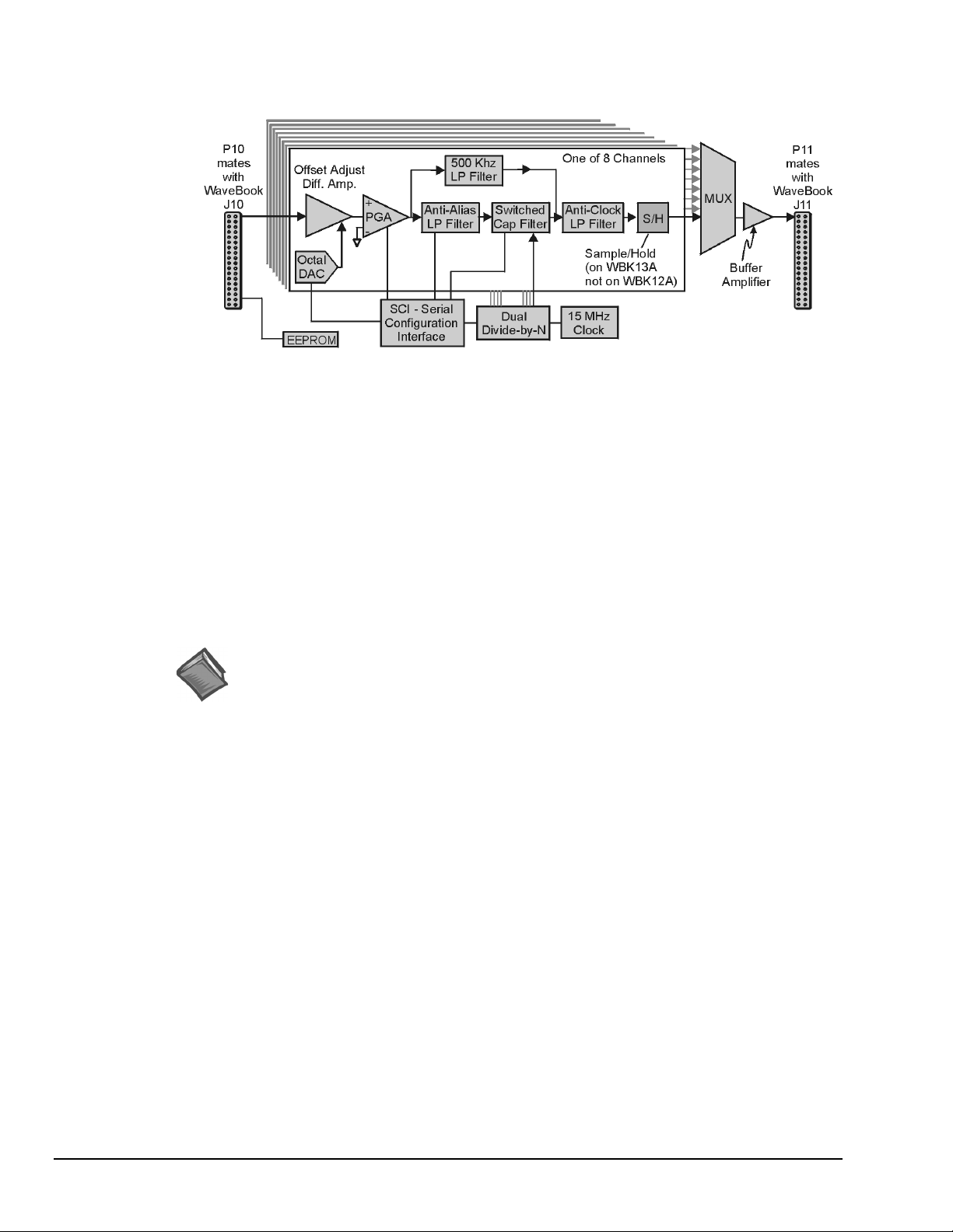
Software Setup
WBK12A and WBK13A Block Diagram
Reference Notes:
➣
Setup information pertaining to power, expansion control, and expansion signal
connections is contained in the System Setup and Power Options chapter of the
WaveBook User’s Manual (p/n 489-0901).
➣
For detailed WaveView information, refer to the WaveView Document Module that is
included on the data acquisition CD. The document can be accessed using the
<View PDFs> button on the CD’s opening screen.
pg. 2, WBK12A and WBK13A
988396
Programmable Low-Pass Filter Cards
Page 3

WBK12A and WBK13A – Specifications
Name/Function:
WBK12A, Programmable Low-Pass Filter Card
WBK13A, Programmable Low-Pass Filter Card With
SSH
Number of Channels
Connector
/516E, and WBK10A
(two 36-pin sockets mate with 36-pin connectors)
Programmable Gain Amplifier Ranges
×1, 2, 5, 10, 20, 50, and 100
Switched Capacitor Filter Cutoff Frequencies Range
400 Hz to 100 kHz
Number of Cutoff Frequencies
Filter Grouping
banks
: Internal to WaveBook/512A, /516, /516A,
Low-Pass Filter
elliptic filter
Low-Pass Filter Type
elliptic or linear phase
Software Selectable Cutoff Frequencies
Octave (kHz) Number of Cutoff
0.400 to 0.780 512
0.780 to 1.570 256
1.57 to 3.15 128
3.15 to 6.3 64
6.3 to 12.5 32
12.5 to 25 16
25 to 50 8
50 to 100 5
: 8
:
: 1024
: 4 channels each in 2 programmable
: Software selectable, 8-pole
: Software selectable,
Frequencies
Low-Pass Filter Frequency Cutoff Range
100 kHz, 75 kHz, 60 kHz...400 Hz,
bypass defined as Fc = 300 kHz/N where N = 3 to 750
Anti-Alias Frequencies
Accuracy
Offset
Aperture Uncertainty
Voltage Droop
Maximum Signal Voltage
:
THD
Number of Cutoff Frequencies Simultaneously Set
Weight
: ±0.03% FS DC, for WaveBook/512A
For WaveBook/516 Series see the table on
page 4 of this document module.
: ±1 LSB max (for WaveBook/512A)
: 1 mV/ms max (0.01 mV/ms typ)
: -65 dB (-70 dB typ) (for WaveBook/512A)
two, one for each 4-channel bank of inputs
: 0.14 kg (0.3 lb)
: determined by software control
: 75 ps max
: ±5.00 VDC (×1)
:
:
Input Voltage Ranges
Before a scan sequence begins, the input voltage ranges can be programmed via software.
The ranges can be expanded as follows:
Unipolar
0 to +10 V
0 to +5 V
0 to +2 V
0 to +1 V
0 to +0.5 V
0 to +0.2 V
0 to +0.1 V
Bipolar
-10 to +10 V
-5 to +5 V
-2 to +2 V
-1 to +1 V
-0.5 to +0.5 V
-0.2 to +0.2 V
-0.1 to +0.1 V
-.05 to + .05 V This range applies to WBK 10A only.
Programmable Gain Amplifier Gain Ranges
: Unipolar applies to WBK 10A only.
: Bipolar applies to
:
WaveBook/516, /516A, /516E, /512A, and WBK10A
: ×1, 2, 5, 10, 20, 50, 100
Programmable Low-Pass Filter Cards
988396
WBK12A and WBK13A, pg. 3
Page 4
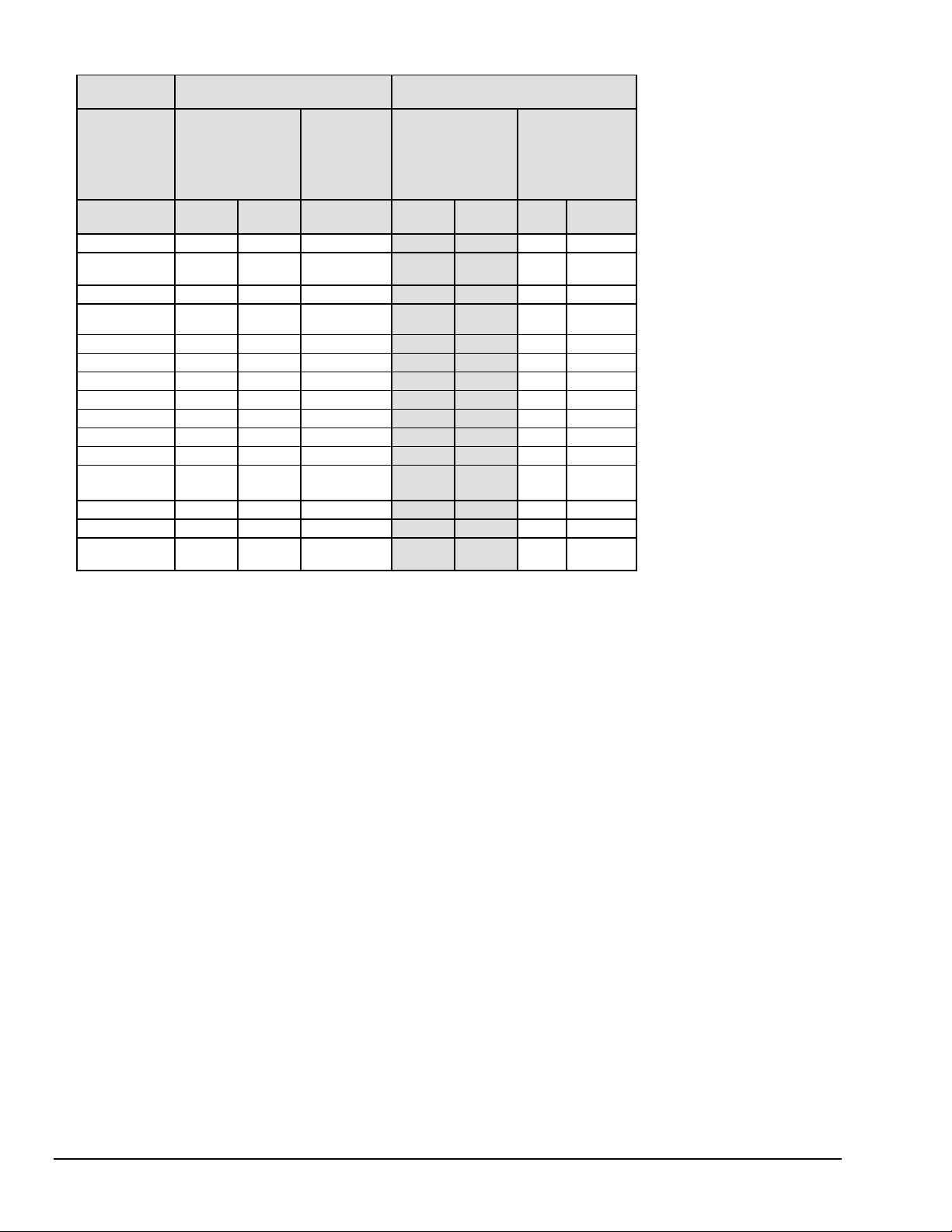
Accuracy and Noise Specifications
(
)
(
y)
(
y)
WaveBook/516 Series
(Alone)
Input Noise
Voltage
Range
Accuracy
(Note 2)
One Year, 18-28
°C
LSB rms
DC-500KHz
One Year, 18-28
(typical)
(Note 4)
%
±
reading
%
±
range
reading
0 to +10V .012% .008% 2 .012% .008% 2.2 2.2
0 to +5V (10A)
0 to +4V
516
.012% .009% 2 .012% .009% 2.2 2.2
0 to +2V .012% .012% 3 .012% .012% 2.2 3
0 to +1V
.012% .018% 3 .012% .018% 2.2 3
10A onl
0 to +.5V .018% .033% 2.2 6
0 to +.2V .018% .08% 2.2 12
0 to +.1V .018% .16% 2.2 20
-10 to +10V .012% .008% 2 .012% .008% 2.2 2.2
-5 to +5V .012% .008% 2 .012% .008% 2.2 2.2
-2 to +2V .012% .009% 2 .012% .009% 2.2 3
-1 to +1V .018% .012% 3 .018% .012% 2.2 3.3
-.5 to +.5V
.018% .018% 5 .018% .018% 2.2 6
(10A only)
-.2 to +.2V .018% .033% 2.2 12
-.1 to +.1V .018% .08% 2.2 20
-.05 to +.05V
10A onl
WaveBook/516 Series
with a WBK12A or a WBK13A
Accuracy
(Note 2)
°C
Input Noise
LSB rms
(typical)
±
%
±
range
1KHz
%
Filter
Bypass
.018% .16% 440
(Note 3)
Filter
Notes
: 1. Specifications assume differential input scan, unfiltered
2. Accuracy specification is exclusive of noise.
3. Unipolar ranges are unavailable for a WaveBook/516 Series with a
WBK11A, W BK12A, or WBK13A option installed.
Unipolar mode is available with WBK10A and any option.
4. Maximum limit is 1.3X typical.
pg. 4, WBK12A and WBK13A
988396
Programmable Low-Pass Filter Cards
Page 5

Predicting Amplitude Loss
The following equations can be used to predict the amplitude loss when passing a signal through either the
anti-alias or clock suppression filter.
Definition of equation terms:
Fin is the signal to be measured.
Falias is the cutoff frequency of the anti-alias filter.
Fclock is the cutoff frequency of the clock suppression filter.
1
1
1
Fin
Falias
1
Fin
Fclock
Err 20 log
Err 20 log
.
.
Total error, in dB, due to both filters is :
Etot 20 log
1
1
Falias
..
Fin
1
1
Fin
Fclock
As an example, with the switched capacitor filter set to 10,000 Hz. and the input frequency set to 6000 Hz.
Fin = 6000
Falias = 33554
Fclock = 14848
Total amplitude loss = sum of both errors = -2.188 dB.
1
1
1
6000
33554
1
6000
14848
1
1
1
6000
33554
1
Fx
Fp
..
..
1
6000
1
14848
1
Fx
1
Fc
E1 20 log
E1 0.71446
E2 20 log
E2 1.47396
E1 E2 2.18843
Etot 20 log
Etot 2.18843
Fx 1 2,8000
Fp 33554
Fc 14848
EFx( ) 20 log
.
=
.
=
=
=
..
Programmable Low-Pass Filter Cards
988396
WBK12A and WBK13A, pg. 5
Page 6

0.25
0.5
0.75
1.25
0
1
EFx()
1.5
1.75
2
2.25
2.5
2.75
3
0 800 1600 2400 3200 4000 4800 5600 6400 7200 8000
Fx
WBK12A & WBK13A, Amplitude Loss in dB due to Anti-alias and Clock Filters
Input signal is swept from 1 to 8000 Hz
switched capacitor filter frequency = 8,000 Hz
anti-alias filter cutoff = 33.554 Hz
clock filter = 14,848 Hz
pg. 6, WBK12A and WBK13A
988396
Programmable Low-Pass Filter Cards
 Loading...