

Page 1
WBK10A
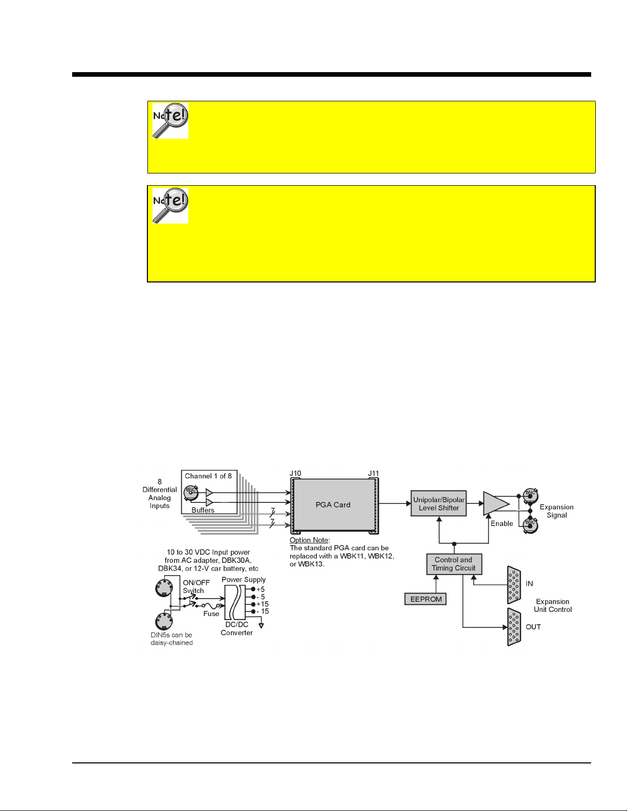
The WBK10A Analog Expansion Module can be used to provide WaveBook with 8 additional differentialanalog-inputs. The WBK10A is equipped with a programmable gain instrumentation amplifier (PGA) and,
like the WaveBook, has a built-in expansion bus.
Up to eight WBK10A modules can be cascaded together for a system capacity of 72 differential channels.
Each module is capable of supporting a WBK11A, WBK12A, or WBK13A option card.
Analog Expansion Module
Important Notice! WaveBook/516E Users
WBK option cards for WaveBook/516E are installed at the factory per customer order.
Users are not to remove or install cards for these products as the cards are not “plug-andplay” for these devices and erroneous signal values could result. If you desire to remove
or add a card to WaveBook/516E contact the factory or your service representative.
Important Notice! WaveBook/516, /516A, /512A, and WBK10A Users
With exception of the WBK30 option, WBK option cards for WaveBook/516, /516A,
/512A, and WBK10A are installed at the factory per customer order. Users are not to
remove or install cards for these products [other than WBK30 series cards] as the cards
are not “plug-and-play” for these devices and erroneous signal values could result. If you
desire to remove or add a card to these products, contact the factory or your service
representative.
Note: WBK10A can be ordered with a PGA, WBK11A, WBK12A, or a WBK13A card installed.
WBK10A Block Diagram
WBK10A, Analog Expansion Module
988397
WBK10A, pg. 1
Page 2
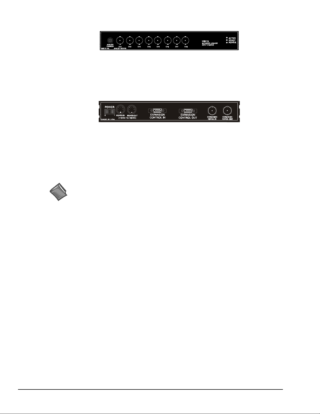
The front panel has the following connectors and indicators:
WBK10A Front Panel
• 1 Analog Common binding post for reference.
• 8 BNC connectors for analog inputs. Channels are labeled 1 through 8.
• 3 Status LEDs (Active, Ready, Power).
The rear panel has a power switch and the following connectors:
WBK10A Rear Panel
•
2 DIN5 connectors [one for Power In, one for Power Out]
• 1 HD-15M Expansion Control In
• 1 HD-15F Expansion Control Out
•
2 BNC connectors [one for analog Expansion Signal In,
one for analog Expansion Signal Out]
Reference Notes:
➣
Setup information pertaining to power, expansion control, and expansion signal connections
is contained in the System Setup and Power Options chapter of the WaveBook User’s
Manual (p/n 489-0901).
➣
For detailed WaveView information, refer to the WaveView Document Module that is
included on the data acquisition CD. The document can be accessed using the
<View PDFs> button on the CD’s opening screen.
pg. 2, WBK10A
988397
WBK10A, Analog Expansion Module
Page 3

Specifications - WaveBook/516, /516A, /516E, and WBK10A
(
)
(
y)
(
y)
Analog Specifications
For either a stand alone WaveBook, or for a WBK10A with a WaveBook
Channel Capacity
WaveBook/516E
WaveBook/516 and /516A
BNC Input Connectors
Input Voltage Ranges (DC Specifications)
Voltage
Range
0 to +10V .012% .008% 2 .012% .008% 2 .012% .008% 2.2 2.2
0 to +5V (10A)
0 to +4V
0 to +2V .012% .012% 3 .012% .012% 3 .012% .012% 2.2 3
0 to +1V
10A onl
0 to +.5V .018% .033% 6 .018% .033% 2.2 6
0 to +.2V .018% .08% 8 .018% .08% 2.2 12
0 to +.1V .018% .16% 15 .018% .16% 2.2 20
-10 to +10V .012% .008% 2 .012% .008% 2 .012% .008% 2.2 2.2
-5 to +5V .012% .008% 2 .012% .008% 2 .012% .008% 2.2 2.2
-2 to +2V .012% .009% 2 .012% .009% 2 .012% .009% 2.2 3
-1 to +1V .018% .012% 3 .018% .012% 3 .018% .012% 2.2 3.3
-.5 to +.5V
(10A only)
-.2 to +.2V .018% .033% 8 .018% .033% 2.2 12
-.1 to +.1V .018% .08% 15 .018% .08% 2.2 20
-.05 to +.05V
10A onl
Notes: 1. Specifications assume differential input scan, unfiltered.
2. Accuracy specification is exclusive of noise.
516
3. Unipolar ranges are not available for WaveBook/516, /516A, or /516E when a WBK11A, W BK12A,
:
: 8 built-in voltage channels, expandable up to 72 channels via WBK options. In addition, WaveBook/516E can
accommodate up to 3 WaveBook/516A, /512A, or WBK40 options, in any combination. Each added on WaveBook can
be expanded up to 72 channels. The maximum W BK41 capacity is 224 T/C channels, 4 analog output channels, 272
digital I/O channels, and 6 counter/timer channels.
: 8 differential, expandable up to 72 differential
: Center conductor is Channel Hi, outer conductor is Channel Low
Standard Unit With WBK11A
Input Noise
Accuracy
One Year, 18-28
±
reading
.012% .009% 2 .012% .009% 2 .012% .009% 2.2 2.2
.012% .018% 3 .012% .018% 3 .012% .018% 2.2 3
.018% .018% 5 .018% .018% 6 .018% .018% 2.2 6
or WBK13A option is installed. Unipolar ranges are available with WBK10A and any option.
(Note 2)
%
%
±
range
°C
LSB rms
DC-500KHz
(typical)
Accuracy
One Year, 18-28
±
reading
.018% .16% 26 .018% .16% 440
(Note 2)
%
±
range
°C
%
(Note 3)
Input Noise
LSB rms
DC-500KHz
(typical)
With WBK12A/13A
Accuracy
One Year, 18-28
±
reading
(Note 2)
%
±
range
°C
1KHz
%
Filter
(Note 3)
Input Noise
LSB rms
(typical)
Filter
Bypass
System Performance:
Differential Nonlinearity:
Total Harmonic Distortion (10Hz-20KHz)
Signal to Noise and Distortion (SINAD, 10Hz-20KHz):
Temperature Coefficient of Accuracy (0-18 and 28-50°C)
Input Resistance
Bias Current
Common Mode Rejection
Input Bandwidth:
Hostile Channel-to-channel Crosstalk (5Vrms input signal, DC-100KHz):
Over-Voltage Protection
WBK10A, Analog Expansion Module
one year, 18-28°C unless otherwise noted
±2 LSB max
: -84dB typical
-74dB typical
:
With PGA and WBK11A:
With WBK12A/13A:
: 5MΩ (single ended); 10MΩ (differential), in parallel with 30pF
: <400 nA (0 to 35°C)
: >70dB minimum; >80dB typical; DC-20KHz
DC to 500KHz
: ±35 V relative to analog common
988397
± (.002% + 0.6 LSB)/°C typical, -10 to +10V range
± (.002% + 1 LSB)/°C typical, -10 to +10V range
Note
: Specifications are subject to change without notice.
-88dB typical
WBK10A, pg. 3
Page 4

PGA Filter
WBK11A Functions
WBK12A, WBK13A Functions
Triggering
Filter Type
Input Voltage Ranges:
Aperture Uncertainty (SSH)
Voltage Droop (SSH)
Input Voltage Ranges:
Low Pass Filter Type
Anti-Aliasing Filters
Low-Pass Filter Frequency Cutoff Range
Filter Grouping:
Aperture Uncertainty (SSH)
Voltage Droop (SSH)
Channel 1 Analog Trigger
Input Signal Range:
Input Characteristics and Protection:
Latency
: 20KHz low pass, Butterworth, 5-pole filter
N=3 to 750
: 300ns
Software programmable prior to a scan sequence
: 75ps max
: 0.01mV/ms typ
Software programmable prior to a scan sequence
: Software selectable, 8-Pole elliptic or linear phase
: Single-pole pre and post filters, automatically set depending on filter frequency selected
: 100KHz, 75KHz, 60KHz…400Hz, bypass (fc=300KHz/N where
4 Channels each in two programmable banks
: 75ps max
: 0.01mV/ms typ
-10 to +10V
Same as channel inputs
Multi-Channel Analog Trigger (up to 72 channels)
Range
Latency
TTL Trigger
Input Signal Range
Input Characteristics
Input Protection:
Latency
Software Trigger
Latency:
Pulse Trigger
Input Signal Range:
Input Characteristics
Input Protection:
Minimum Pulse Width:
Latency
External Clock
Connector:
Input Signal Range:
Input Characteristics:
Input Protection:
Delay: 200ns
Signal Slew Rate Requirement:
Rate:
Divisor ratio:
Clock Counter Accuracy:
Clock Counter Range:
:
: Selectable per channel to input range
: 2us/channel, plus 4us maximum
:
: 0-5V
: TTL-compatible with 10K ohm pull-up resistor
Zener clamped –0.7 to +5V
: 300ns
100us typical
0-5V
: 75 ohms
±10V maximum
100ns
: 300ns
Available on DB25 digital input
5V TTL compatible
50K ohms pull up (to +5V) in parallel with 50pF
Zener clamped –0.7 to +5V
20V/us minimum
Up to 1MHz
Divide by 1 through 255, selectable
<0.02% error
0.01Hz to 100KHz
pg. 4, WBK10A
988397
WBK10A, Analog Expansion Module
Page 5

Sequencer
Operation
Depth
Channel-to-Channel Rate
Maximum Repeat Rate
Minimum Repeat Rate
Expansion Channel Sample Rate
:
Programmable for channel, gain, and for unipolar/bipolar range in random order
: 128 location
: 1.0-1.1us/channel, all channels equal
: 1MHz
: 100 seconds per scan
: Same as on-board channels
High-Speed Digital Inputs/General-Purpose Outputs
Connector:
Configuration
Input Characteristics:
Output Characteristics:
Output Updates
Input/Output Protection:
DB25 Female
: 16 TTL-compatible pins, selectable for input or output
TTL-compatible
ALS TTL output in series with 33 ohms
: Outputs may be changed via program control
Diode clamped to ground and +5V
Period Counter
Operation
Clock Counter Accuracy
Clock Counter Range
: Internal counter calculates and reports the external clock’s period;
counter can be read with each scan
General Specifications
Warm-up:
Environment
Power Consumption
Input Power Range
Input Power Fuse F201
Vibration:
PC Communication
Channel Capacity
Dimensions
Weight
30 minutes to rated specifications
:
Operating:
Storage:
/516E
/516, /516A & /512A:
MIL STD 810E, Category 1 and 10
/516E
/516, /516A & /512A:
/516E
/516, /516A & /512A:
:
/516E
/516, /516A & /512A:
:
/516E
/516, /516A & /512A
: <0.02% error
: 0.01 Hz to 100 kHz
0-50°C, 0-95% RH (non-condensing)
-20 to 70°C
:
: 1.8A max @ 15 VDC
1.4A max @ 15VDC
: 10 VDC to 30 VDC
: 4A MINI ATO; See chapter 9 for fuse replacement instructions.
:
: 10/100BaseT Ethernet
Enhanced Parallel Port (EPP)
:
: 8 built-in voltage channels, expandable up to 72 channels via WBK options. In
addition, WaveBook/516E can accommodate up to 3 WaveBook/516A, /512A, or
WBK40 options, in any combination. Each added on WaveBook can be expanded
up to 72 channels. The maximum WBK41 capacity is 224 T/C channels, 4 analog
output channels, 272 digital I/O channels, and 6 counter/timer channels.
8 built-in voltage channels, expandable up to 72 channels via WBK
options
: 285 mm wide x 220 mm deep x 70 mm high (11 x 8.5 x 2.70 inches)
285 mm wide x 220 deep x 45 mm high (11 x 8.5 x 1.75 inches)
: 1.9 kg (4.2 lbs)
: 1.5 kg (3.3 lbs)
WBK10A, Analog Expansion Module
988397
WBK10A, pg. 5
Page 6

pg. 6, WBK10A
988397
WBK10A, Analog Expansion Module
 Loading...