

Page 1
Option Cards and Modules for
WaveBook Systems
Measurement Computing Corporation
**
WBK Options
**
USER’S MANUAL
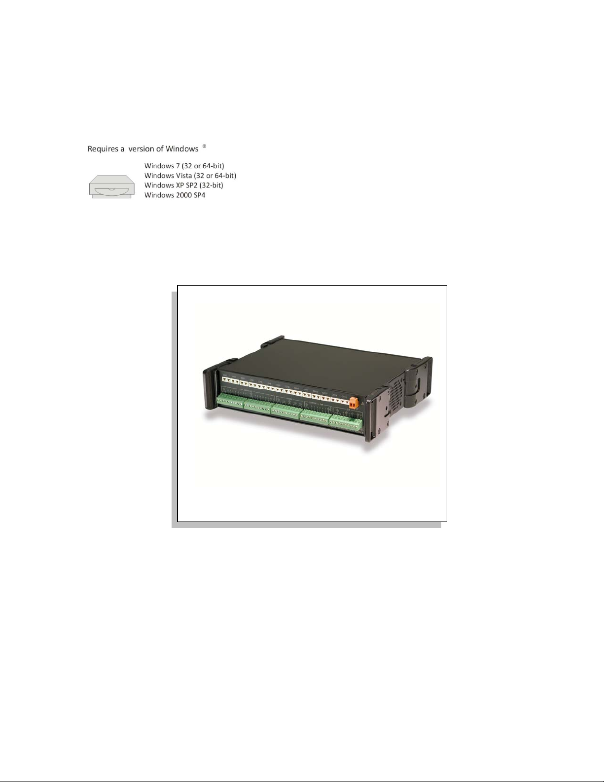
** Neither Windows Vista nor Windows 7 support WaveBook/512A, /516, or /516A.
Windows Vista and Windows 7 both support WaveBook/516E.
*372187C-01*
372187C-01 489-0902 rev 4.4
10 Commerce Way
Norton, MA 02766
USA
Phone: (508) 946-5100
Fax: (508) 946-9500
e-mail: info@measurementcomputing.com
Page 2
Your warranty is as stated on the product warranty card. You may contact MCC by phone,
fax machine, or e-mail in regard to warranty-related issues.
Refer all service to qualified personnel. This caution symbol warns of possible personal injury or equipment damage
This warning symbol is used in this manual or on the equipment to warn of possible injury or death from electrical
Warranty Information
Limitation of Liability
MCC cannot be held liable for any damages resulting from the use or misuse of this product.
Copyright, Trademark, and Licensing Notice
All IOtech documentation, software, and hardware are copyright with all rights reserved. No part of this product may be
copied, reproduced or transmitted by any mechanical, photographic, electronic, or other method without prior written
consent. IOtech product names are trad emarked; other product names, as applicable, ar e trademarks of their respective
holders. All supplied IOtech software (including miscellaneous support files, drivers, and sample programs) may only be
used on one installation. You may make archival backup copies.
CE Notice
Many IOtech products carry the CE marker indicating they comply with the safety and emissions standards of the
European Community. As applicable, include Declarations of Conformity on our website. The declarations state which
standards and operating conditions apply.
Warnings, Cautions, Notes, and Tips
under noted conditions. Follow all safety standards of professional practice and the recommendations in this manual.
Using this equipment in ways other than described in this manual can present serious safety hazards or cause equipment
damage.
shock under noted conditions.
This ESD caution symbol urges proper handling of equipment or components sensitive to damage from electrostatic
discharge. Proper handling guidelines include the use of grounded anti-static mats and wrist straps, ESD-protective
bags and cartons, and related procedures.
This symbol indicates the message is important, but is not of a Warning or Caution category. These notes can be of
great benefit to the user, and should be read.
In this manual, the book symbol always precedes the words “Reference Note.” This type of note identifies the location
of additional information that may prove helpful. References may be made to other chapters or other documentation.
Tips provide advice that may save time during a procedure, or help to clarify an issue. Tips may include additional
reference.
Specifications and Calibration
Specifications are subject to change without notice. Significant changes will be addressed in an addendum or revision to
the manual. As applicable, MCC calibrates its hardware to published specifications. Periodic hardware calibration is not
covered under the warranty and must be performed by qualified personnel as specified in this manual. Improper
calibration procedures may void the warranty.
WaveBook/512A, /516, /516A, /516E 988789 WaveBook User’s Manual iii
Page 3
Note:
PDF
489-0902
CAUTION
CAUTION
CAUTIONCAUTION
Using this equipment in ways other than described in this manual can cause
personal injury or equipment damage. Before setting up and using your
equipment, you should read all documentation that covers your system.
Pay special attention to Warnings and Cautions.
During software installation, Adobe
install onto your hard drive as a part of product support. The default location is in the
Programs group, which can be accessed from the Windows Desktop. You can also
access the PDF documents directly from the CD vis the <View PDFs> button on the
CD’s opening screen. Refer to the PDF documentation for details regarding both
hardware and software.
A copy of the Adobe Acrobat Reader® is included on your CD. The Reader provides
a means of reading and printing the PDF documents. Note that hardcopy versions of the
manuals can be ordered from the factory.
®
PDF versions of user manuals will automatically
WBK Option Cards and Modules User’s Manual
The WBK Option Cards and Modules Manual discusses each of the WBK products
available at the time of print. The following documents are related.
PDF
489-0901
PDF
481-0901
PDF
PDF
PDF
1008-0901
WaveBook User’s Manual,
Explains how to make signal and power connections and how to install software and
product support for the WaveBook/512A, /516, /516A, & /516E.
WaveBook User’s Manual,
Explains how to make signal and power connections and how to install software and
product support for the WaveBook/512 and WaveBook/512H.
for WaveBook/512A, /516, /516A, & /516E
for WaveBook/512 and /512H
WaveView
Discusses how to install and use this “out-of-the-box” data acquisition program that
was designed for use with WaveBook systems.
Post Acquisition Data Analysis User’s Guide
Programmer’s Manual
The programmer’s manual pertains to developing custom programs using Applications
Program Interface (API) commands.
Note that the install CD-ROM includes WaveBook program examples.
iv
988296
WBK Option Cards and Modules
Page 4
Table of Contents
An Introduction to WBKs
WBK10A – Analog Expansion Module
WBK11A – Simultaneous Sample and Hold (SSH) Card
WBK12A and WBK13A – Programmable Filter Cards
WBK14 – Dynamic Signal Conditioning Module
WBK15 – 5B Isolated Signal Conditioning Module
WBK16 – Strain Gage Module
WBK17 – Counter-Input Module with Quadrature Encoder Support
WBK18 – Dynamic Signal Conditioning Module
WBK20A – PCMCIA/EPP Interface Card and Cable
WBK21 – ISA/EPP Interface Plug-In Board
WBK23 – PCI/EPP Interface Plug-In Board
WBK25 – Ethernet Interface Module User's Guide (p/n 1087-0901)
WBK30 – WaveBook Memory Options
WBK40 and WBK41 – Thermocouple and Multi-Function I/O Modules
PDF Note:
WBK61 and WBK62 – High Voltage Adapters
Glossary
CAUTION
CAUTION
CAUTIONCAUTION
Using the equipment in ways other than described in this manual can cause personal injury or
equipment damage. Pay special attention to all cautions and warnings.
Reference Notes:
➣
Information (not available at the time of publication), will be made available in ReadMe files,
or in supplemental documentation.
➣
For programming-related information refer to the separate Programmer’s Manual,
p/n 1008-0901. (See PDF Note, below).
➣
WaveBook/512A, WaveBook/516, and WaveBook/516A are covered in the WaveBook User’s
Manual, p/n 489-0901.
➣
WaveBook/512 and WaveBook/512H are covered in WaveBook User’s Manual, p/n 481-0901.
During software installation, Adobe
®
PDF versions of user manuals will automatically install onto
your hard drive as a part of product support. The default location is in the Programs group, which
can be accessed from the Windows Desktop. Refer to the PDF documentation for details regarding
both hardware and software. The PDF documents can also be read directly from the CD using the
<View PDFs> button on the CD’s opening screen.
A copy of the Adobe Acrobat Reader
®
is included on your CD. The Reader provides a means of
reading and printing the PDF documents. Note that hardcopy versions of the manuals can be ordered
from the factory.
WBK Option Cards and Modules
v
967896
Page 5
An Introduction to WBKs
What are WBKs?…… 1
How do WaveBooks and WBKs Interrelate? ……4
How are WaveBook Systems Powered? …… 5
How are WBK Modules Mounted to other Modules or to WaveBooks? …… 5
What are WBKs?
WBKs are WaveBook system options that exist in the form of cards or modules. The WBK options can be used to
enhance and/or expand your WaveBook system.
Internally, WaveBook has room for one signal-conditioning card. Externally, one or more expansion modules can be
used with a WaveBook.
Reference Note:
The WBK option cards and modules that follow are detailed immediately after this introduction.
The information is presented in alpha-numerical order and includes product specifications.
WBK Options
Note: The items represented in the table are not shown to the same scale.
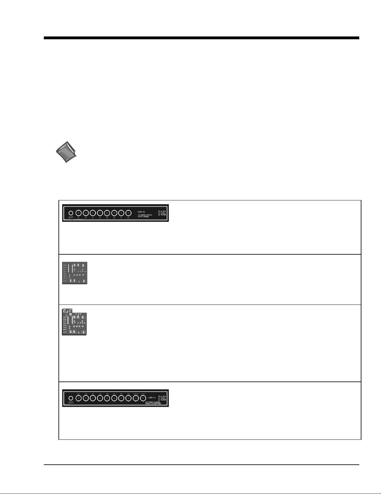
Each WBK10A module can be used to provide W aveBook with 8
additional differential-analog-inputs. The modules are equipped with
WBK10A
Analog Expansion Module
8 Channels via BNC Connectors
a programmable gain instrumentation amplifier (PGA) and, like the
WaveBook, each has a built-in expansion bus.
Up to eight WBK10A modules can be cascaded together for a
system capacity of 72 differential channels. Each module is capable
of supporting a WBK11A, WBK12A, or WBK13A option card.
WBK11A
Simultaneous Sample & Hold Card (8 channels)
WBK12A
Programmable Low-Pass Filter Card
(8 channels)
WBK13A
Programmable Low-Pass Filter Card with SSH
(8 channels)
WBK14
Dynamic Signal Conditioning Module
8 Channels via BNC Connectors
The WBK11A card can simultaneously sample 8 channels and can
be installed inside a WaveBook or in a WBK10A module. The cards
allow for concurrent (<150 ns) capture of multiple input channels and
virtually eliminate channel-to-channel time skewing.
The WBK11A option is factory install only.
WBK12A and WBK13A are 8-channel programmable low-pass filter
cards for use with WaveBook data acquisition systems. These cards
install directly into a WaveBook or WBK10A module and provide
programmable low-pass filtering over all channels. Multiple WBK12A
and WBK13A cards can be installed in one system for up to 72
channels. All of the cards’ low-pass filters and cutoff frequencies are
configured via software.
WBK13A cards have the additional capability of sampling all
channels at the same time.
The WBK12A and WBK13A options are factory install only.
The WBK14 is a dynamic analog signal input module. It enables
WaveBooks to interface with piezoelectric transducers that include
accelerometers, microphones, and force/pressure transducers.
Each WBK14 channel has a:
• current source for transducer biasing
• high-pass filter
• programmable gain amplifier
• anti-aliasing low-pass filter
• simultaneous sample-and-hold (SSH) amplifiers
WBK Option Cards and Modules
988397
Introduction 1
Page 6
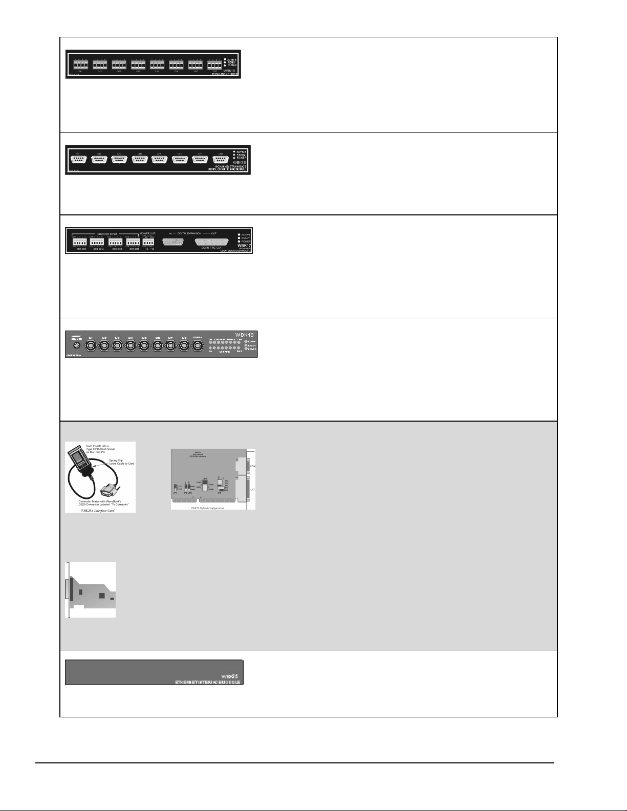
WBK15
8-Slot 5B Signal Conditioning Module
8 channels via 5B Modules
WBK16
Strain-Gage Module
8 channels via Standard Female DB9
WBK17
Counter-Input Module with Quadrature Encoder
Support
8 channels via Removable Screw Terminal Blocks
WBK18
Dynamic Signal Conditioning Module with
Transducer Electronic Data Sheet support
(T.E.D.S).
8 channels via BNC Connectors
WBK20A, WBK21, and WBK23
– Three Interface options that can be used to obtain an Enhanced Parallel Port.
The WBK15 module provides for a diverse range of signals available
through optional 5B modules. Measurement types include: LVDT,
potentiometer, isolated current loop, ±10mV to ±40V inputs,
linearized RTD, thermocouple, frequency-to-voltage, and strain
gage.
See latest catalog or contact your sales representative in regard to
the types of 5B Modules available for your application.
WBK16 is an 8-channel strain-gage signal-conditioning module. Up
to eight WBK16 modules (64 channels) can be accommodated by
the WaveBook and scanned at 1 µs/channel. Almost all bridge
configurations are supported via a bridge-completion network and
software. High-gain differential-amplifier applications are also
supported. Software controls bridge configuration, gain, offset,
excitation voltage, polarity, filtering, and the calibration process.
The WBK17 is an 8-channel multi-function counter/encoder module
for use with Wavebook/512A, /516, /516A, and /516E. Each of the
high-speed, 32-bit counter channels can be configured for counter,
period, pulse width, time between edges, or encoder modes. All
channels are capable of measuring analog inputs that are digitized by
the WaveBook.
WBK18 provides 8 channels of dynamic signal input for WaveBook
systems. Each channel on the WBK18 has independent, software
control for AC or DC coupling, ICP biasing (0 or 4 mA), and low-pass
filter cut-off frequency. The 8-pole Butterworth filter on each channel
is programmable from 5 Hz to 50 kHz, in a 1-2-5 progression. The
filter can also be bypassed, resulting in a bandwidth of greater than
200 kHz.
WBK20A
PC-Card /EPP
Interface & Cable
WBK21
ISA/EPP Interface
Plug-in Board
WBK23
PCI/EPP Interface Plug-In Board
WBK25
10/100BaseT Ethernet Interface Module
WBK20A – PCMCIA/EPP Interface Card and Cable
For linking WaveBook to a Notebook PC. This interface
provides an Enhanced Parallel Port via a PC-Card Slot.
WBK21 – ISA/EPP Interface Plug-in Board
For linking WaveBook to a desktop PC. This interface
provides an Enhanced Parallel Port via an ISA Bus-slot.
WBK23 – PCI/EPP Interface Plug-In Board
(For linking WaveBook to a desktop PC)
Provides an Enhanced Parallel Port from a PCI Bus-slot.
These three interfaces are shipped with separate documentation and
are not detailed in this manual.
The WBK25 provides high-speed Ethernet connectivity for
WaveBook, DaqBook and WBK40 series products. The WBK25
contains one 10/100BaseT Ethernet port for connection to a PC,
and three expansion ports that can attach to any model of
WaveBook, DaqBook, WBK40 Series option, or any combination
of these devices.
2 Introduction
988397
WBK Option Cards and Modules
Page 7
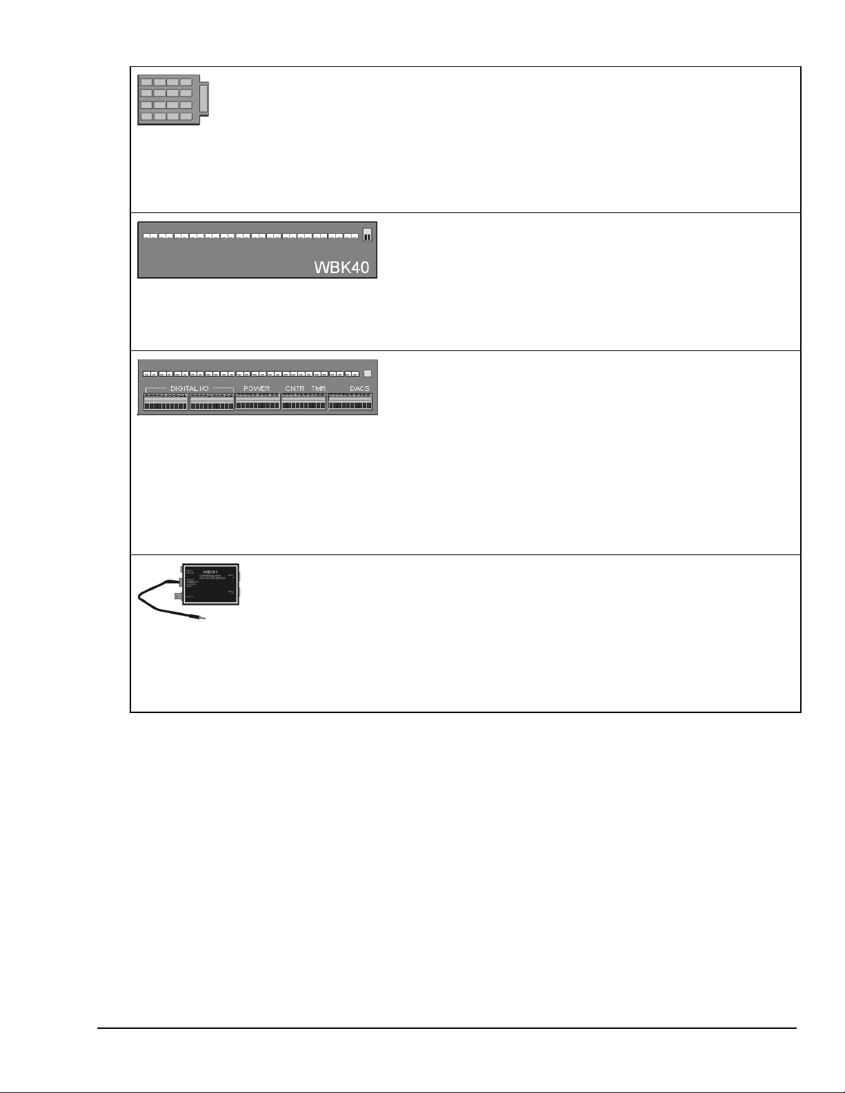
WBK30
WaveBook Memory Options
WBK40
Thermocouple Input Module
14 channels via Mini-T/C Connectors
WBK41
Multi-Function I/O Module
14 Thermocouple channels via Mini-T/C Connectors
40 Digital I/O Lines
4 Counter Inputs
2 Timer Outputs
(Optional) 4 Analog Channel Outputs
WBK30 is a DRAM-based memory board that installs inside a
WaveBook. There are three models of WBK30 available; each
significantly increases the capacity of a WaveBook's standard data
buffer of 64 K samples. Capacities are as follows:
WBK30/16 — 16 MB
WBK30/64 — 64 MB
WBK30/128 — 128 MB
Note: For WaveBook/516E the WBK30 option, if selected, must be
factory installed.
The WBK40 attaches to any one of the three expansion ports on the
WaveBook/516E or the WBK25, and provides 14 thermocouple input
channels. The 14 built-in TC channels accept any type of
thermocouple, including types J, K, S, T, E, B, R, and N. Mini-TC
connections make it quick and easy to attach thermocouples. The
WBK40 can be expanded in 14 channel increments using the
DBK84 TC expansion module. A total of 15 DBK84s can be attached
to one WBK40, for a total TC channel capacity of 224 channels.
The WBK41 attaches to any one of the three expansion ports on the
WaveBook/516E or WBK25 and provides 14 thermocouple inputs,
40 digital I/O lines, 4 counter inputs, and 2 timer outputs. The
WBK41 can also be supplied with an internal, 4-channel, 16-bit,
100-kHz analog output option.
The built-in TC channels on the WBK41 are accessed via mini-TC
connectors on the front panel. The counter/timer functions and 16
bits of digital I/O are accessed via removable front panel screwterminal connectors. Additional digital I/O and expansion connectors
are located at the rear of the WBK41.
The WBK41 can be easily expanded beyond its built-in channel
capacity. A maximum WBK41 system can include up to 224 TC
input channels, 272 digital I/O channels, 4 analog output channels,
4 counter input channels and 2 timer output channels.
WBK61 and WBK62
WBK61: High-Voltage Adapter with 200:1 Voltage
Divider (1 channel)
WBK62: High-Voltage Adapter with 20:1 Voltage
Divider (1 channel)
WBK61 and WBK62 are single-channel high-voltage adapters that
can be used with the WaveBook or with a WBK10A expansion
module. In addition, W BK61 and WBK62 can be used in conjunction
with WBK11A, W BK12A, and W BK13A cards.
WBK61 and WBK62 include safety-style banana-jacks for the high
and low inputs, and 60-inch (152 cm) cables with probe tips and
alligator clips for easy input connection.
WBK Option Cards and Modules
988397
Introduction 3
Page 8
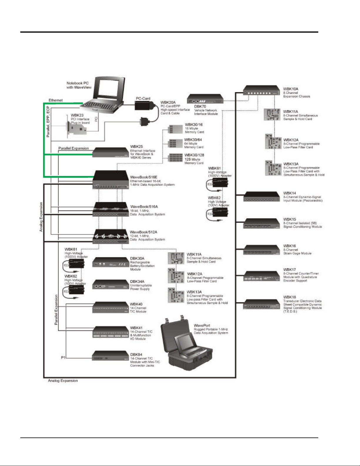
How do WaveBooks and WBKs Interrelate?
WaveBooks and WBKs interrelate when they become part of the same data-acquisition system. The
relationship can be broken down into enhancement, expansion, or both. The following illustrates the
relationship of various system components.
WaveBook System Components
4 Introduction 988397 WBK Option Cards and Modules
Page 9

How are WaveBook Systems Powered?
Power supply input voltage to the WaveBook and to the system modules, e.g., WBK10A, WBK14,
WBK15, WBK16, WBK17, WBK18, WBK40, and WBK41 must be in the range of 10 VDC to 30 VDC
and can come from an appropriate AC-to-DC adapter or a battery option. The latter includes DBK power
modules and batteries in the range of 10 VDC to 30 VDC.
Note: Power supply input to the WBK25 Ethernet Module must be in the range of 10 VDC to 20 VDC.
Available AC-to-DC adapters include the TR-40U (supplied), which has an input of 90-264 VAC and a
output rating of 2.2 amps @ 15 VDC.
Battery options include the DBK30A, DBK34A, and other 10 to 30 VDC sources, such as car batteries.
The DBK30A provides 14 VDC and when fully charged has a storage capacity of 3.4 A⋅hr; car batteries
have much higher capacities. The basic formula for battery life is:
Runtime (hr) = Battery capacity (A⋅⋅⋅⋅hr) / Current load (A)
System cards, e.g., WBK11A, WBK12A, and WBK13A, get power from their host WaveBook or their host
WBK10A expansion module.
Before connecting your system to power, you need to know the power requirements of your specific system.
A calculation method that incorporates the use of worktables is presented in Chapter 2 of the WaveBook
User’s Manual (p/n 489-0901).
Reference Notes:
•
In the WaveBook User’s Manual (p/n 489-0901), the System Setup and Power Options
chapter includes examples of power connections for different WaveBook system
scenarios. In these examples the included TR-40U power adapters are used.
• In the WaveBook User’s Manual (p/n 489-0901), the WaveBook Operation Reference
chapter includes discussions of power supplies other than the TR-40U.
How are WBK Modules Mounted to other Modules or to WaveBooks?
The fastener panels and associated
screws are from fastener-panel kit,
p/n 262-0801.
Fastener Panels
Using Fastener Panels to Stack a WaveBook and two WBK Modules (use of the handle is optional)
WBK Option Cards and Modules
988397
(p/n HA-111)
Introduction 5
Page 10

WBK modules can be stacked using fastener panels, sometimes referred to as splice plates. The panels
provide a means of stacking modules to create one rigid assembly. The Fastener Panel Kit, p/n 262-0801,
is available from the factory and consists of two metal plates and the necessary mounting screws.
A Fastener-Panel Handle (p/n HA-111) is also available from the factory. HA-111 consists of 1 handle and
two mounting screws.
The previous figure illustrates the simplicity of the mounting process.
Note:
When used with a WBK16, WaveBook/516, WaveBook/516A, or WaveBook/512A, fastener
panels will partially block the vents on the side of the module. This partial blocking of vents
does not jeopardize the cooling process.
6 Introduction
988397
WBK Option Cards and Modules
Page 11
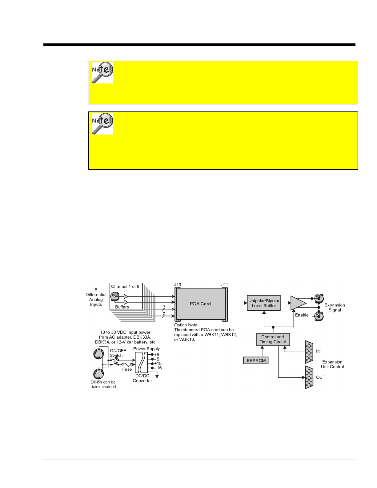
WBK10A
The WBK10A Analog Expansion Module can be used to provide WaveBook with 8 additional differentialanalog-inputs. The WBK10A is equipped with a programmable gain instrumentation amplifier (PGA) and,
like the WaveBook, has a built-in expansion bus.
Up to eight WBK10A modules can be cascaded together for a system capacity of 72 differential channels.
Each module is capable of supporting a WBK11A, WBK12A, or WBK13A option card.
Analog Expansion Module
Important Notice! WaveBook/516E Users
WBK option cards for WaveBook/516E are installed at the factory per customer order.
Users are not to remove or install cards for these products as the cards are not “plug-andplay” for these devices and erroneous signal values could result. If you desire to remove
or add a card to WaveBook/516E contact the factory or your service representative.
Important Notice! WaveBook/516, /516A, /512A, and WBK10A Users
With exception of the WBK30 option, WBK option cards for WaveBook/516, /516A,
/512A, and WBK10A are installed at the factory per customer order. Users are not to
remove or install cards for these products [other than WBK30 series cards] as the cards
are not “plug-and-play” for these devices and erroneous signal values could result. If you
desire to remove or add a card to these products, contact the factory or your service
representative.
Note: WBK10A can be ordered with a PGA, WBK11A, WBK12A, or a WBK13A card installed.
WBK10A Block Diagram
WBK10A, Analog Expansion Module
988397
WBK10A, pg. 1
Page 12
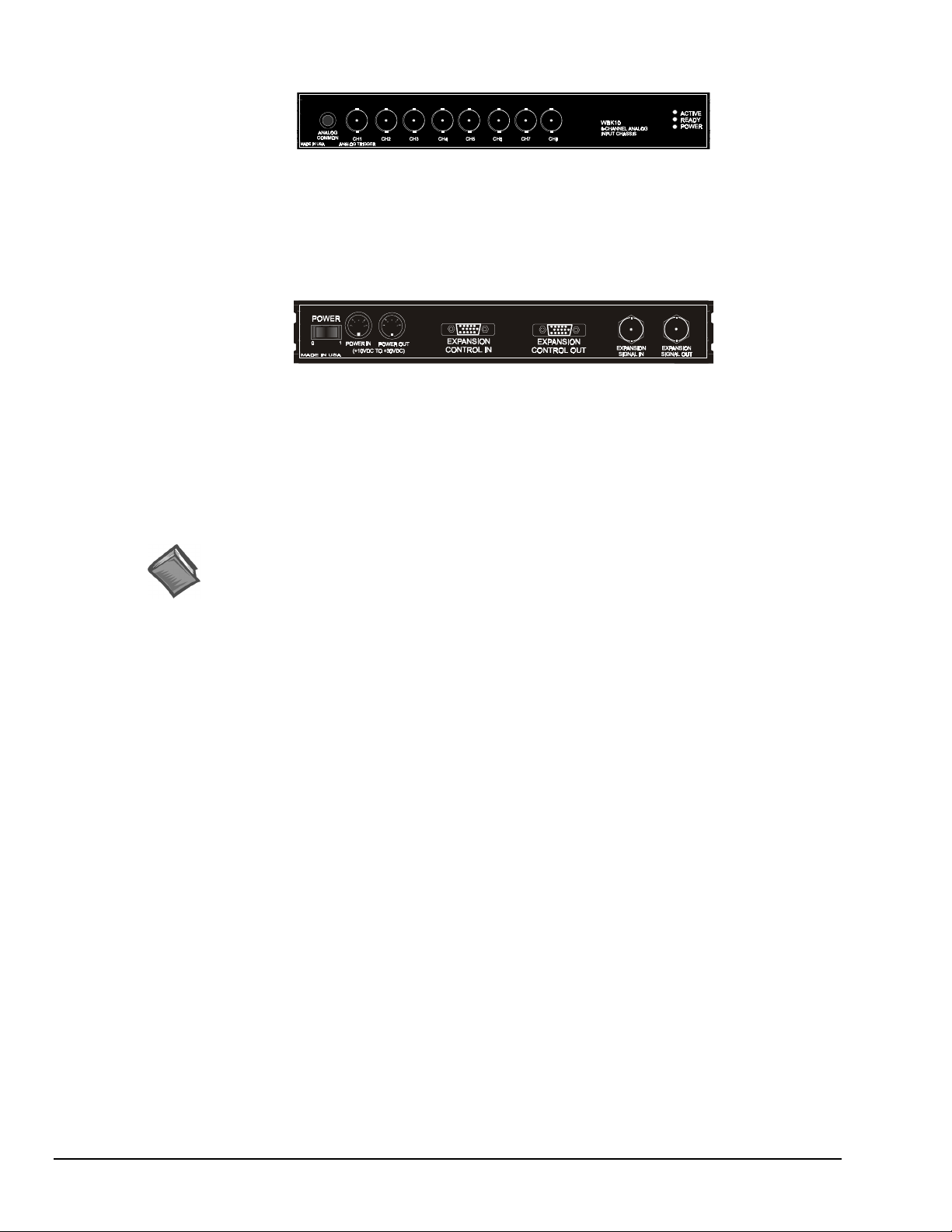
The front panel has the following connectors and indicators:
WBK10A Front Panel
• 1 Analog Common binding post for reference.
• 8 BNC connectors for analog inputs. Channels are labeled 1 through 8.
• 3 Status LEDs (Active, Ready, Power).
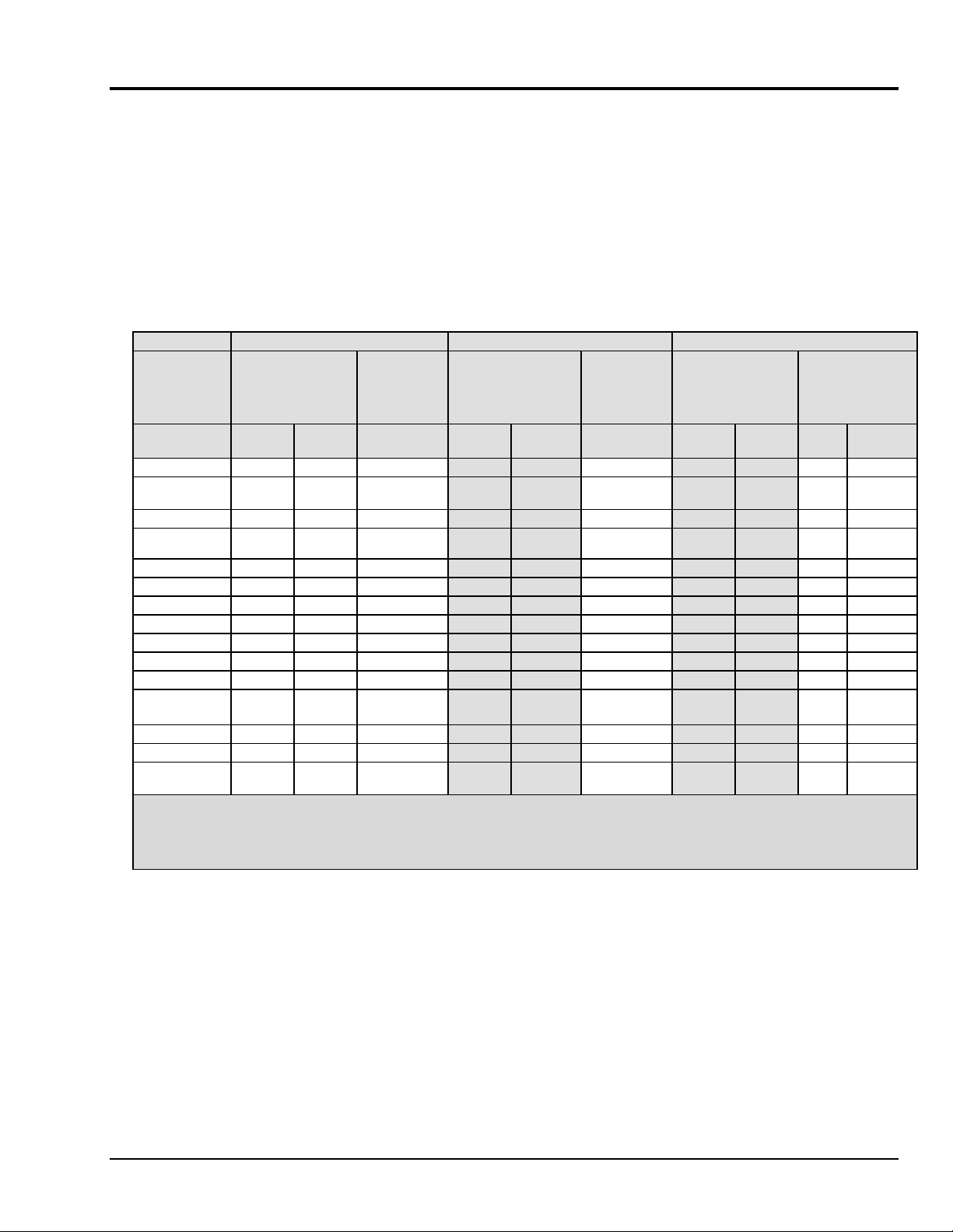
The rear panel has a power switch and the following connectors:
WBK10A Rear Panel
•
2 DIN5 connectors [one for Power In, one for Power Out]
• 1 HD-15M Expansion Control In
• 1 HD-15F Expansion Control Out
•
2 BNC connectors [one for analog Expansion Signal In,
one for analog Expansion Signal Out]
Reference Notes:
➣
Setup information pertaining to power, expansion control, and expansion signal connections
is contained in the System Setup and Power Options chapter of the WaveBook User’s
Manual (p/n 489-0901).
➣
For detailed WaveView information, refer to the WaveView Document PDF that is
included on the data acquisition CD. The document can be accessed using the
<View PDFs> button on the CD’s opening screen.
pg. 2, WBK10A
988397
WBK10A, Analog Expansion Module
Page 13
Specifications - WaveBook/516, /516A, /516E, and WBK10A
(
)
(
y)
(
y)
Analog Specifications
For either a stand alone WaveBook, or for a WBK10A with a WaveBook
Channel Capacity
WaveBook/516E
WaveBook/516 and /516A
BNC Input Connectors
Input Voltage Ranges (DC Specifications)
Voltage
Range
0 to +10V .012% .008% 2 .012% .008% 2 .012% .008% 2.2 2.2
0 to +5V (10A)
0 to +4V
0 to +2V .012% .012% 3 .012% .012% 3 .012% .012% 2.2 3
0 to +1V
10A onl
0 to +.5V .018% .033% 6 .018% .033% 2.2 6
0 to +.2V .018% .08% 8 .018% .08% 2.2 12
0 to +.1V .018% .16% 15 .018% .16% 2.2 20
-10 to +10V .012% .008% 2 .012% .008% 2 .012% .008% 2.2 2.2
-5 to +5V .012% .008% 2 .012% .008% 2 .012% .008% 2.2 2.2
-2 to +2V .012% .009% 2 .012% .009% 2 .012% .009% 2.2 3
-1 to +1V .018% .012% 3 .018% .012% 3 .018% .012% 2.2 3.3
-.5 to +.5V
(10A only)
-.2 to +.2V .018% .033% 8 .018% .033% 2.2 12
-.1 to +.1V .018% .08% 15 .018% .08% 2.2 20
-.05 to +.05V
10A onl
Notes: 1. Specifications assume differential input scan, unfiltered.
2. Accuracy specification is exclusive of noise.
516
3. Unipolar ranges are not available for WaveBook/516, /516A, or /516E when a WBK11A, WBK12A,
:
: 8 built-in voltage channels, expandable up to 72 channels via WBK options. In addition, WaveBook/516E can
accommodate up to 3 WaveBook/516A, /512A, or WBK40 options, in any combination. Each added on WaveBook can
be expanded up to 72 channels. The maximum W BK41 capacity is 224 T/C channels, 4 analog output channels, 272
digital I/O channels, and 6 counter/timer channels.
: 8 differential, expandable up to 72 differential
: Center conductor is Channel Hi, outer conductor is Channel Low
Standard Unit With WBK11A
Input Noise
Accuracy
One Year, 18-28
±
reading
.012% .009% 2 .012% .009% 2 .012% .009% 2.2 2.2
.012% .018% 3 .012% .018% 3 .012% .018% 2.2 3
.018% .018% 5 .018% .018% 6 .018% .018% 2.2 6
or WBK13A option is installed. Unipolar ranges are available with WBK10A and any option.
(Note 2)
%
%
±
range
°C
LSB rms
DC-500KHz
(typical)
Accuracy
One Year, 18-28
±
reading
.018% .16% 26 .018% .16% 440
(Note 2)
%
±
range
°C
%
(Note 3)
Input Noise
LSB rms
DC-500KHz
(typical)
With WBK12A/13A
Accuracy
One Year, 18-28
±
reading
(Note 2)
%
±
range
°C
1KHz
%
Filter
(Note 3)
Input Noise
LSB rms
(typical)
Filter
Bypass
System Performance:
Differential Nonlinearity:
Total Harmonic Distortion (10Hz-20KHz)
Signal to Noise and Distortion (SINAD, 10Hz-20KHz):
Temperature Coefficient of Accuracy (0-18 and 28-50°C)
Input Resistance
Bias Current
Common Mode Rejection
Input Bandwidth:
Hostile Channel-to-channel Crosstalk (5Vrms input signal, DC-100KHz):
Over-Voltage Protection
WBK10A, Analog Expansion Module
one year, 18-28°C unless otherwise noted
±2 LSB max
: -84dB typical
-74dB typical
:
With PGA and WBK11A:
With WBK12A/13A:
: 5MΩ (single ended); 10MΩ (differential), in parallel with 30pF
: <400 nA (0 to 35°C)
: >70dB minimum; >80dB typical; DC-20KHz
DC to 500KHz
: ±35 V relative to analog common
988397
± (.002% + 0.6 LSB)/°C typical, -10 to +10V range
± (.002% + 1 LSB)/°C typical, -10 to +10V range
Note
: Specifications are subject to change without notice.
-88dB typical
WBK10A, pg. 3
Page 14

PGA Filter
WBK11A Functions
WBK12A, WBK13A Functions
Triggering
Filter Type
Input Voltage Ranges:
Aperture Uncertainty (SSH)
Voltage Droop (SSH)
Input Voltage Ranges:
Low Pass Filter Type
Anti-Aliasing Filters
Low-Pass Filter Frequency Cutoff Range
Filter Grouping:
Aperture Uncertainty (SSH)
Voltage Droop (SSH)
Channel 1 Analog Trigger
Input Signal Range:
Input Characteristics and Protection:
Latency
: 20KHz low pass, Butterworth, 5-pole filter
N=3 to 750
: 300ns
Software programmable prior to a scan sequence
: 75ps max
: 0.01mV/ms typ
Software programmable prior to a scan sequence
: Software selectable, 8-Pole elliptic or linear phase
: Single-pole pre and post filters, automatically set depending on filter frequency selected
: 100KHz, 75KHz, 60KHz…400Hz, bypass (fc=300KHz/N where
4 Channels each in two programmable banks
: 75ps max
: 0.01mV/ms typ
-10 to +10V
Same as channel inputs
Multi-Channel Analog Trigger (up to 72 channels)
Range
Latency
TTL Trigger
Input Signal Range
Input Characteristics
Input Protection:
Latency
Software Trigger
Latency:
Pulse Trigger
Input Signal Range:
Input Characteristics
Input Protection:
Minimum Pulse Width:
Latency
External Clock
Connector:
Input Signal Range:
Input Characteristics:
Input Protection:
Delay: 200ns
Signal Slew Rate Requirement:
Rate:
Divisor ratio:
Clock Counter Accuracy:
Clock Counter Range:
:
: Selectable per channel to input range
: 2us/channel, plus 4us maximum
:
: 0-5V
: TTL-compatible with 10K ohm pull-up resistor
Zener clamped –0.7 to +5V
: 300ns
100us typical
0-5V
: 75 ohms
±10V maximum
100ns
: 300ns
Available on DB25 digital input
5V TTL compatible
50K ohms pull up (to +5V) in parallel with 50pF
Zener clamped –0.7 to +5V
20V/us minimum
Up to 1MHz
Divide by 1 through 255, selectable
<0.02% error
0.01Hz to 100KHz
pg. 4, WBK10A
988397
WBK10A, Analog Expansion Module
Page 15

Sequencer
Operation
Depth
Channel-to-Channel Rate
Maximum Repeat Rate
Minimum Repeat Rate
Expansion Channel Sample Rate
:
Programmable for channel, gain, and for unipolar/bipolar range in random order
: 128 location
: 1.0-1.1us/channel, all channels equal
: 1MHz
: 100 seconds per scan
: Same as on-board channels
High-Speed Digital Inputs/General-Purpose Outputs
Connector:
Configuration
Input Characteristics:
Output Characteristics:
Output Updates
Input/Output Protection:
DB25 Female
: 16 TTL-compatible pins, selectable for input or output
TTL-compatible
ALS TTL output in series with 33 ohms
: Outputs may be changed via program control
Diode clamped to ground and +5V
Period Counter
Operation
Clock Counter Accuracy
Clock Counter Range
: Internal counter calculates and reports the external clock’s period;
counter can be read with each scan
General Specifications
Warm-up:
Environment
Power Consumption
Input Power Range
Input Power Fuse F201
Vibration:
PC Communication
Channel Capacity
Dimensions
Weight
30 minutes to rated specifications
:
Operating:
Storage:
/516E
/516, /516A & /512A:
MIL STD 810E, Category 1 and 10
/516E
/516, /516A & /512A:
/516E
/516, /516A & /512A:
:
/516E
/516, /516A & /512A:
:
/516E
/516, /516A & /512A
: <0.02% error
: 0.01 Hz to 100 kHz
0-50°C, 0-95% RH (non-condensing)
-20 to 70°C
:
: 1.8A max @ 15 VDC
1.4A max @ 15VDC
: 10 VDC to 30 VDC
: 4A MINI ATO; See chapter 9 for fuse replacement instructions.
:
: 10/100BaseT Ethernet
Enhanced Parallel Port (EPP)
:
: 8 built-in voltage channels, expandable up to 72 channels via WBK options. In
addition, WaveBook/516E can accommodate up to 3 WaveBook/516A, /512A, or
WBK40 options, in any combination. Each added on WaveBook can be expanded
up to 72 channels. The maximum WBK41 capacity is 224 T/C channels, 4 analog
output channels, 272 digital I/O channels, and 6 counter/timer channels.
8 built-in voltage channels, expandable up to 72 channels via WBK
options
: 285 mm wide x 220 mm deep x 70 mm high (11 x 8.5 x 2.70 inches)
285 mm wide x 220 deep x 45 mm high (11 x 8.5 x 1.75 inches)
: 1.9 kg (4.2 lbs)
: 1.5 kg (3.3 lbs)
WBK10A, Analog Expansion Module
988397
WBK10A, pg. 5
Page 16
WBK11A
Description
The WBK11A is a simultaneous sample-and-hold card (SSH) that provide a means of obtaining concurrent
(<150 ns) capture from up to 8 input channels. The card virtually eliminates channel-to-channel time
skewing. The card is controlled by the acquisition system’s base WaveBook.
Simultaneous Sample & Hold Card
Important Notice! WaveBook/516E Users
WBK option cards for WaveBook/516E are installed at the factory per customer order.
Users are not to remove or install cards for these products as the cards are not “plug-andplay” for these devices and erroneous signal values could result. If you desire to remove
or add a card to WaveBook/516E contact the factory or your service representative.
Important Notice! WaveBook/516, /516A, /512A, and WBK10A Users
With exception of the WBK30 option, WBK option cards for WaveBook/516, /516A,
/512A, and WBK10A are installed at the factory per customer order. Users are not to
remove or install cards for these products [other than WBK30 series cards] as the cards
are not “plug-and-play” for these devices and erroneous signal values could result. If you
desire to remove or add a card to these products, contact the factory or your service
representative.
The WBK11A can be installed inside a WaveBook or in a WBK10A series module; however, it must be
installed by a qualified service representative (see the important notice above).
When using a WaveBook with an SSH channel enabled, the per-channel sample rates are
reduced. The rate reduction is the same as that which would occur if another channel were
added. The per-channel rate (with SSH enabled) is:
1 MHz / (n+1), where n is the number of active channels.
The WBK11A SSH card can accommodate higher gains than the main unit because its gains are fixed for
each channel prior to the acquisition. You can use WaveView to set each channel to the ranges listed in the
specifications on page 2. All channels equipped with SSH circuitry are sampled simultaneously as a
system.
P10
mates
with
WaveBook
J10
One of 8 Channels (Typical)
Offset Adjust
Diff. Amp.
+
PGA
-
Octal
DAC
SCI - Serial
Configuration Interface
Sample/
MUX
Hold
Buffer
Amplif ier
P11
mates
with
WaveBook
J11
WBK11A – SSH Card
WBK11A Block Diagram
988396
WBK11A, pg. 1
Page 17

Hardware Setup
Configuration
All WBK11A configurations are controlled by software. There are no hardware settings.
Reference Note:
For detailed WaveView information refer to the WaveView Document. A PDF version of
the document can be accessed from the data acquisition CD via the <View PDFs> button
on the CD’s opening screen.
Installation
There is no user installation permitted. See notes on page 1.
WBK11A – Specifications
Name/Function:
Number of Channels
Connectors
a 36 pin-socket connector mates with a 36-pin connector
Accuracy
Offset
Aperture Uncertainty
Voltage Droop
Maximum Signal Voltage
: ±0.025% FS for WaveBook/512A applications.
: ±1 LSB max
Input Voltage Ranges
Before a scan sequence begins, the input voltage ranges can be programmed via software.
The ranges can be expanded as follows:
Unipolar
0 to +10 V
0 to +5 V
0 to +2 V
0 to +1 V
0 to +0.5 V
0 to +0.2 V
0 to +0.1 V
Bipolar
: Bipolar applies to
-10 to +10 V
-5 to +5 V
-2 to +2 V
-1 to +1 V
-0.5 to +0.5 V
-0.2 to +0.2 V
-0.1 to +0.1 V
-.05 to + .05 V This range applies to WBK 10A only.
WBK11A; 8-Channel Simultaneous Sample-and-Hold Card
: 8
: Internal to the WaveBook/512 series, or WaveBook/516 series device;
For WaveBook/516 Series applications, see the table on page 3 of this WBK11A document module.
: 75 ps max
: 0.1 mV/ms max
: ±5.00 VDC (×1)
:
: Unipolar applies to WBK 10A only.
WaveBook/516, /516A, /516E, /512A, and WBK10A
Programmable Gain Amplifier Gain Ranges
Weight
: 0.14 kg (0.3 lb)
pg. 2, WBK11A
: ×1, 2, 5, 10, 20, 50, 100
988396
WBK11A – SSH Card
Page 18

Accuracy and Noise Specifications
(
)
(
y)
(
y)
WaveBook/516 Series
(Alone)
Voltage
Range
Accuracy
(Note 2)
One Year, 18-28
°C
Input Noise
LSB rms
DC-500KHz
(typical)
(Note 4)
%
±
reading
%
±
range
0 to +10V .012% .008% 2 .012% .008% 2
0 to +5V (10A)
0 to +4V
516
.012% .009% 2 .012% .009% 2
0 to +2V .012% .012% 3 .012% .012% 3
0 to +1V
.012% .018% 3 .012% .018% 3
10A onl
0 to +.5V .018% .033% 6
0 to +.2V .018% .08% 8
0 to +.1V .018% .16% 15
-10 to +10V .012% .008% 2 .012% .008% 2
-5 to +5V .012% .008% 2 .012% .008% 2
-2 to +2V .012% .009% 2 .012% .009% 2
-1 to +1V .018% .012% 3 .018% .012% 3
-.5 to +.5V
.018% .018% 5 .018% .018% 6
(10A only)
-.2 to +.2V .018% .033% 8
-.1 to +.1V .018% .08% 15
-.05 to +.05V
10A onl
WaveBook/516 Series
with a WBK11A
(Note 3)
Input Noise
Accuracy
(Note 2)
One Year, 18-28
°C
LSB rms
DC-500KHz
(typical)
%
±
reading
%
±
range
.018% .16% 26
Notes
: 1. Specifications assume differential input scan, unfiltered.
2. Accuracy specification is exclusive of noise.
3. Unipolar ranges unavailable for a WaveBook/516, /516A, or /516E
that has a WBK11A, WBK12A, or WBK13A option installed.
Unipolar mode is available with WBK10A and any option.
4. Maximum limit is 1.3X typical.
WBK11A – SSH Card
988396
WBK11A, pg. 3
Page 19
WBK12A and WBK13A
Important Notice! WaveBook/516E Users
WBK option cards for WaveBook/516E are installed at the factory per customer order.
Users are not to remove or install cards for these products as the cards are not “plug-andplay” for these devices and erroneous signal values could result. If you desire to remove
or add a card to WaveBook/516E contact the factory or your service representative.
Important Notice! WaveBook/516, /516A, /512A, and WBK10A Users
With exception of the WBK30 option, WBK option cards for WaveBook/516, /516A,
/512A, and WBK10A are installed at the factory per customer order. Users are not to
remove or install cards for these products [other than WBK30 series cards] as the cards
are not “plug-and-play” for these devices and erroneous signal values could result. If you
desire to remove or add a card to these products, contact the factory or your service
representative.
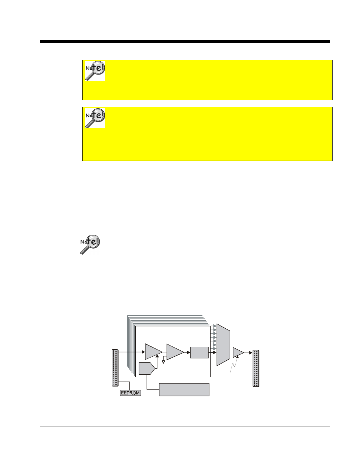
Description
The WBK12A and WBK13A are 8-channel programmable low-pass filter cards for use with 1-MHz
WaveBook data acquisition systems. These cards install directly into a WaveBook or WBK10A module and
provide programmable low-pass filtering over all channels. Multiple WBK12A and WBK13A cards can be
installed in one system for up to 72 channels. All of the cards’ low-pass filters and cutoff frequencies are
configured via software.
Programmable Low-Pass Filter Cards
The WBK13A card has the additional capability of sampling all channels at the same time. If more than one
WBK13A card is installed [within one system] all channels will be sampled within 100 ns of each other.
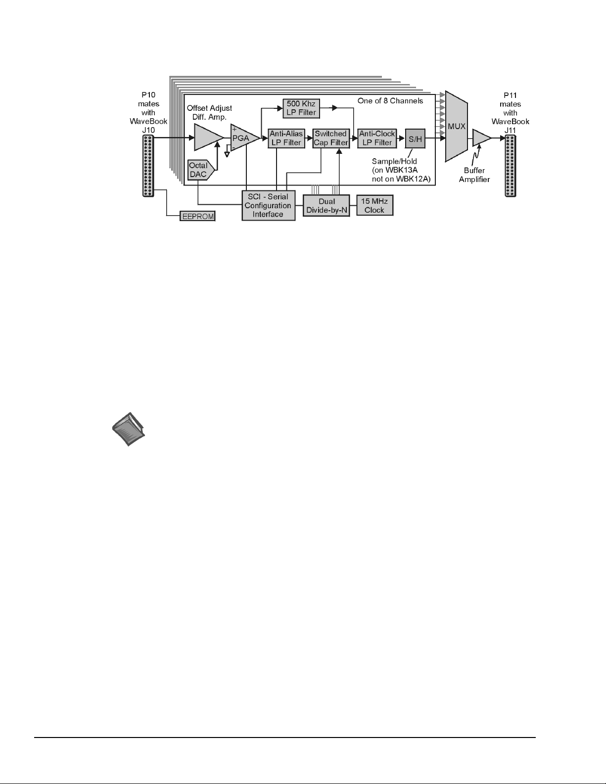
Features of the WBK12A and WBK13A include:
• Anti-Alias Low-Pass Filters. Each card provides 8 input channels, arranged in two 4-channel banks;
the filter and cutoff frequency configurations are applied per bank. The cards’ filters can be configured
as either an 8-pole elliptic filter with cutoff frequencies of 400 Hz to 100 kHz, or an 8-pole linearphase filter with 400 Hz to 50 kHz cutoff frequencies.
• 500 Khz Low Pass Filter. You can individually configure channels to bypass the programmable filter.
The bypass option results in a 1-pole low-pass filter at approximately 500 kHz.
• Cutoff Frequencies. The WBK12A and WBK13A provide 748 discrete cutoff frequencies that can be
determined exactly by the formula Fc = 300 kHz/N; where the integer N = 3 to 750. Alternatively, you
can configure any channel to bypass the programmable filter entirely, resulting in a 1-pole low-pass
filter at about 500 kHz.
• Programmable-Gain Amplifiers. The cards’ programmable-gain instrumentation amplifiers can be
software selected to various gains on a per channel basis. The gains are set prior to the beginning of an
acquisition sequence and cannot be changed during an acquisition.
• Simultaneous Sample-and-Hold (SSH) (WBK13 only). In addition to the filtering capability of the
WBK12A, the WBK13A provides per channel SSH. Simultaneous sampling of all channels occurs at
the start of a scan sequence.
When using a WaveBook with an SSH channel enabled, the per-channel sample rates
are reduced. The rate reduction is the same as that which would occur if another
channel were added. The per-channel rate (with SSH enabled) is:
1 MHz / (n+1), where n is the number of active channels.
Programmable Low-Pass Filter Cards
988396
WBK12A and WBK13A, pg. 1
Page 20
Hardware Setup
Configuration
All WBK12A and WBK13A series configurations are controlled by software. There are no hardware
settings.
Installation
There is no user installation permitted. See notes on page 1.
Software Setup
WBK12A and WBK13A Block Diagram
Reference Notes:
➣
Setup information pertaining to power, expansion control, and expansion signal
connections is contained in the System Setup and Power Options chapter of the
WaveBook User’s Manual (p/n 489-0901).
➣
For detailed WaveView information, refer to the WaveView Document PDF that is
included on the data acquisition CD. The document can be accessed using the
<View PDFs> button on the CD’s opening screen.
pg. 2, WBK12A and WBK13A
988396
Programmable Low-Pass Filter Cards
Page 21
WBK12A and WBK13A – Specifications
Name/Function:
WBK12A, Programmable Low-Pass Filter Card
WBK13A, Programmable Low-Pass Filter Card With
SSH
Number of Channels
Connector
/516E, and WBK10A
(two 36-pin sockets mate with 36-pin connectors)
Programmable Gain Amplifier Ranges
×1, 2, 5, 10, 20, 50, and 100
Switched Capacitor Filter Cutoff Frequencies Range
400 Hz to 100 kHz
Number of Cutoff Frequencies
Filter Grouping
banks
: Internal to WaveBook/512A, /516, /516A,
Low-Pass Filter
elliptic filter
Low-Pass Filter Type
elliptic or linear phase
Software Selectable Cutoff Frequencies
Octave (kHz) Number of Cutoff
0.400 to 0.780 512
0.780 to 1.570 256
1.57 to 3.15 128
3.15 to 6.3 64
6.3 to 12.5 32
12.5 to 25 16
25 to 50 8
50 to 100 5
: 8
:
: 1024
: 4 channels each in 2 programmable
: Software selectable, 8-pole
: Software selectable,
Frequencies
Low-Pass Filter Frequency Cutoff Range
100 kHz, 75 kHz, 60 kHz...400 Hz,
bypass defined as Fc = 300 kHz/N where N = 3 to 750
Anti-Alias Frequencies
Accuracy
Offset
Aperture Uncertainty
Voltage Droop
Maximum Signal Voltage
:
THD
Number of Cutoff Frequencies Simultaneously Set
Weight
: ±0.03% FS DC, for WaveBook/512A
For WaveBook/516 Series see the table on
page 4 of this document module.
: ±1 LSB max (for WaveBook/512A)
: 1 mV/ms max (0.01 mV/ms typ)
: -65 dB (-70 dB typ) (for WaveBook/512A)
two, one for each 4-channel bank of inputs
: 0.14 kg (0.3 lb)
: determined by software control
: 75 ps max
: ±5.00 VDC (×1)
:
:
Input Voltage Ranges
Before a scan sequence begins, the input voltage ranges can be programmed via software.
The ranges can be expanded as follows:
Unipolar
0 to +10 V
0 to +5 V
0 to +2 V
0 to +1 V
0 to +0.5 V
0 to +0.2 V
0 to +0.1 V
Bipolar
-10 to +10 V
-5 to +5 V
-2 to +2 V
-1 to +1 V
-0.5 to +0.5 V
-0.2 to +0.2 V
-0.1 to +0.1 V
-.05 to + .05 V This range applies to WBK 10A only.
Programmable Gain Amplifier Gain Ranges
: Unipolar applies to WBK 10A only.
: Bipolar applies to
:
WaveBook/516, /516A, /516E, /512A, and WBK10A
: ×1, 2, 5, 10, 20, 50, 100
Programmable Low-Pass Filter Cards
988396
WBK12A and WBK13A, pg. 3
Page 22

Accuracy and Noise Specifications
(
)
(
y)
(
y)
WaveBook/516 Series
(Alone)
Input Noise
Voltage
Range
Accuracy
(Note 2)
One Year, 18-28
°C
LSB rms
DC-500KHz
One Year, 18-28
(typical)
(Note 4)
%
±
reading
%
±
range
reading
0 to +10V .012% .008% 2 .012% .008% 2.2 2.2
0 to +5V (10A)
0 to +4V
516
.012% .009% 2 .012% .009% 2.2 2.2
0 to +2V .012% .012% 3 .012% .012% 2.2 3
0 to +1V
.012% .018% 3 .012% .018% 2.2 3
10A onl
0 to +.5V .018% .033% 2.2 6
0 to +.2V .018% .08% 2.2 12
0 to +.1V .018% .16% 2.2 20
-10 to +10V .012% .008% 2 .012% .008% 2.2 2.2
-5 to +5V .012% .008% 2 .012% .008% 2.2 2.2
-2 to +2V .012% .009% 2 .012% .009% 2.2 3
-1 to +1V .018% .012% 3 .018% .012% 2.2 3.3
-.5 to +.5V
.018% .018% 5 .018% .018% 2.2 6
(10A only)
-.2 to +.2V .018% .033% 2.2 12
-.1 to +.1V .018% .08% 2.2 20
-.05 to +.05V
10A onl
WaveBook/516 Series
with a WBK12A or a WBK13A
Accuracy
(Note 2)
°C
Input Noise
LSB rms
(typical)
±
%
±
range
1KHz
%
Filter
Bypass
.018% .16% 440
(Note 3)
Filter
Notes
: 1. Specifications assume differential input scan, unfiltered
2. Accuracy specification is exclusive of noise.
3. Unipolar ranges are unavailable for a WaveBook/516 Series with a
WBK11A, W BK12A, or W BK13A option installed.
Unipolar mode is available with WBK10A and any option.
4. Maximum limit is 1.3X typical.
pg. 4, WBK12A and WBK13A
988396
Programmable Low-Pass Filter Cards
Page 23
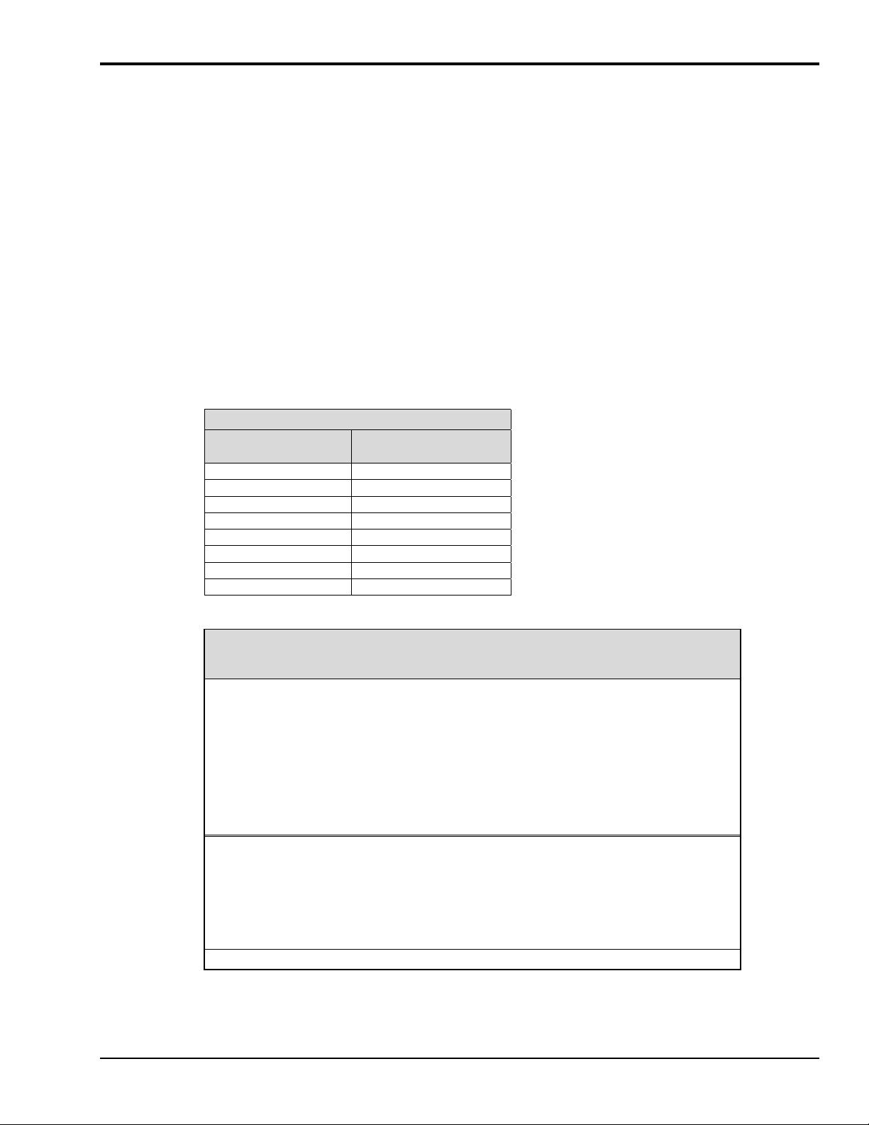
Predicting Amplitude Loss
The following equations can be used to predict the amplitude loss when passing a signal through either the
anti-alias or clock suppression filter.
Definition of equation terms:
Fin is the signal to be measured.
Falias is the cutoff frequency of the anti-alias filter.
Fclock is the cutoff frequency of the clock suppression filter.
1
1
1
Fin
Falias
1
Fin
Fclock
Err 20 log
Err 20 log
.
.
Total error, in dB, due to both filters is :
Etot 20 log
1
1
Falias
..
Fin
1
1
Fin
Fclock
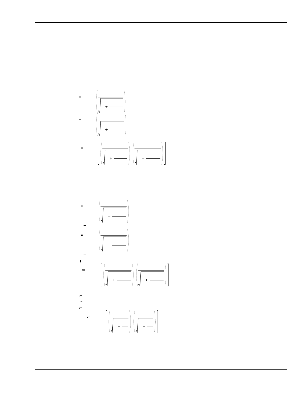
As an example, with the switched capacitor filter set to 10,000 Hz. and the input frequency set to 6000 Hz.
Fin = 6000
Falias = 33554
Fclock = 14848
Total amplitude loss = sum of both errors = -2.188 dB.
1
1
1
33554
1
14848
1
1
6000
6000
1
6000
33554
1
Fx
Fp
..
..
1
6000
1
14848
1
Fx
1
Fc
E1 20 log
E1 0.71446
E2 20 log
E2 1.47396
E1 E2 2.18843
Etot 20 log
Etot 2.18843
Fx 1 2,8000
Fp 33554
Fc 14848
EFx( ) 20 log
.
=
.
=
=
=
..
Programmable Low-Pass Filter Cards
988396
WBK12A and WBK13A, pg. 5
Page 24
0.25
0.5
0.75
1.25
0
1
EFx()
1.5
1.75
2
2.25
2.5
2.75
3
0 800 1600 2400 3200 4000 4800 5600 6400 7200 8000
Fx
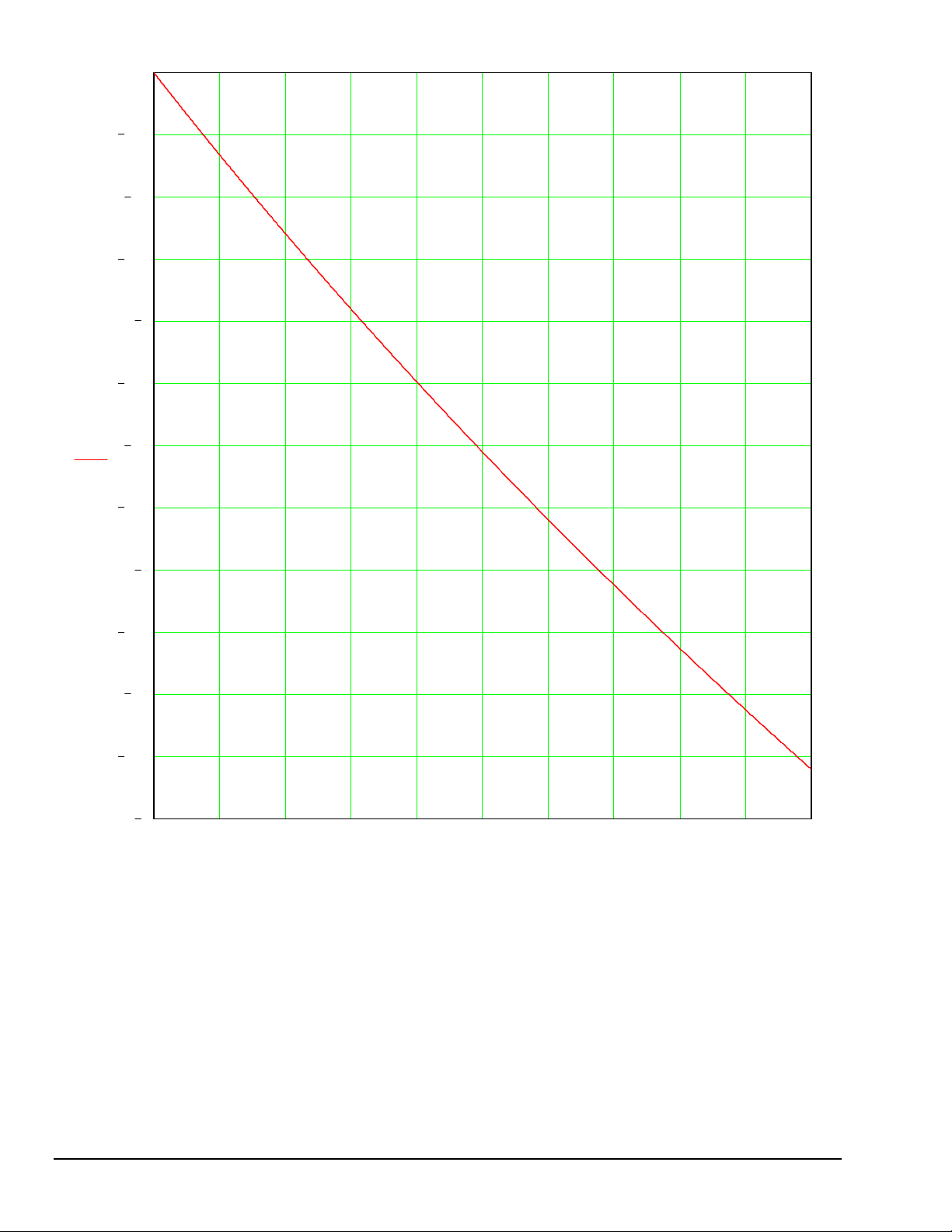
WBK12A & WBK13A, Amplitude Loss in dB due to Anti-alias and Clock Filters
Input signal is swept from 1 to 8000 Hz
switched capacitor filter frequency = 8,000 Hz
anti-alias filter cutoff = 33.554 Hz
clock filter = 14,848 Hz
pg. 6, WBK12A and WBK13A
988396
Programmable Low-Pass Filter Cards
Page 25

WBK14
Dynamic Signal Input Module
Description…… 1
Current Source …… 2
High-Pass Filter (HPF) …… 2
Programmable Gain Amplifier (PGA) …… 2
Programmable Low-Pass Filter Phase Equalizer …… 3
Programmable Low-Pass Anti-Aliasing Filter…… 2
Simultaneous Sample and Hold…… 3
Excitation Source …… 3
Calibration …… 3
Hardware Setup …… 4
Configuration…… 4
Power…… 4
Assembly…… 4
Software Setup …… 5
Using Accelerometers with WBK14 …… 6
Overview …… 6
Accelerometer Specification Parameters …… 6
Electrical Grounding…… 8
Cable Driving…… 8
WBK14 – Specifications …… 9
Description
The WBK14 is a dynamic analog signal input module for the WaveBook data acquisition system. The
WBK14 provides a complete system to interface to piezoelectric transducers that include accelerometers,
microphones, force/pressure transducers, and others.
Reference Note:
Information regarding accelerometers begins on page 6 of this document module.
Each WBK14 channel has a:
•
current source for transducer biasing
•
high-pass filter
• programmable gain amplifier
•
anti-aliasing low-pass filter
•
simultaneous sample-and-hold (SSH) amplifiers
The gain, filter cut-off frequencies and current biasing levels are software programmable.
WBK14 includes a built-in programmable excitation source. This source stimulates dynamic systems for
transfer function measurements, and serves as a reference signal for calibration.
WBK14, Dynamic Signal Input Module
988396
WBK14, pg. 1
Page 26
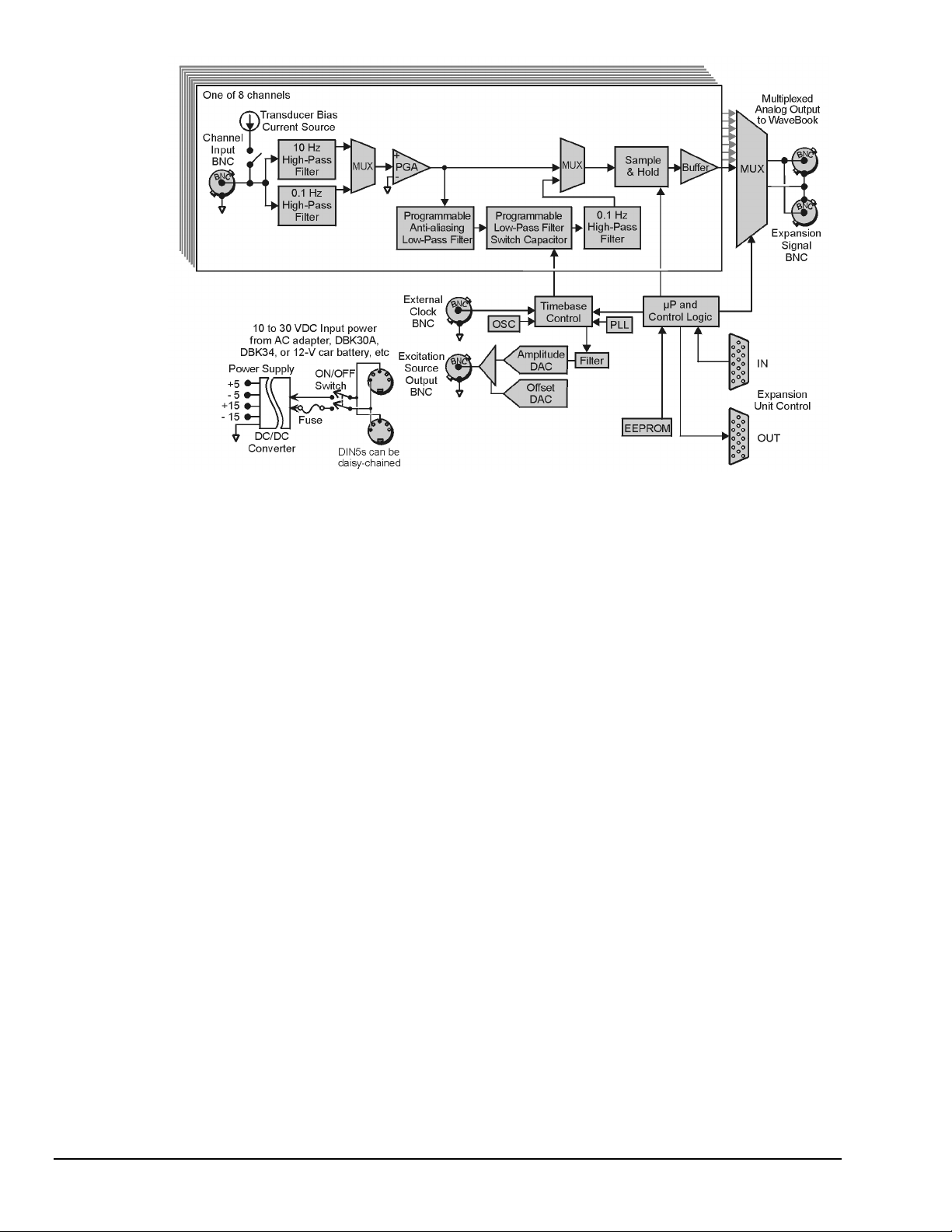
Current Source
WBK14 provides constant current to bias ICP transducers. Two current levels (2 mA or 4 mA) with
voltage compliance of 27 V can be selected via software. The bias current is sourced through the center
conductor of a coaxial lead and returns to the WBK14 by the outer conductor. The output impedance is
larger than 1 MΩ and presents virtually no loading effect on the transducer’s output. For applications that
do not require bias, the current source can be removed from the BNC input by opening a relay contact.
The current sources are applied to (or removed from) the input in channel groups of two; i.e.,
channels 1-2, 3-4, 5-6, 7-8.
High-Pass Filters (HPF)
Each WBK14 channel has three High-Pass Filters (HPFs) with a 3-dB cut-off frequency (Fc). Two filters
are at 0.1 Hz and the other is 10 Hz. The 0.1-Hz HPF filters are single-pole RC filters. They are primarily
used to couple vibration signals. The 10-Hz HPF is a 2-pole Butterworth type that can be used to couple
acoustic signals or attenuate setup-induced low-frequency signals; since these can reduce the dynamic range
of the measurement (for example when using tape recorders as signal sources).
Programmable Gain Amplifier (PGA)
The HPF removes the DC voltage from the input signal. A PGA amplifies the AC voltage with flat response
up to 500 kHz. Each channel has a PGA with programmable gains (1, 2, 5, 10, 20, 50, and 100) and a
software-controlled DAC for offset nulling. The WBK14 measures only bipolar signals up to 5 V peak.
WBK14 Block Diagram
Programmable Low-Pass Anti-Aliasing Filter
The first filter stage is a programmable 2-pole continuous-time low-pass filter. The filter provides more than
65 dB alias protection to the next filter stage. In addition, it fine-tunes the phase shift of the channel to
optimize the phase-matching between channels. At calibration, the phase shift of each channel is measured
and stored in an EEPROM that is read at configuration.
WBK14, pg. 2
988396
WBK14, Dynamic Signal Input Module
Page 27

Programmable Low-Pass Filter, Switch-Capacitor
Most of the signal alias rejection is performed by an 8-pole Butterworth filter. This filter is implemented
with a switch-capacitor network driven by a programmable clock (timebase control). Each channel has an
independent clock whose frequency determines the 3-dB cut-off frequency of the filter. The switchcapacitor filter provides no attenuation at the clock frequency—hence, the need for the continuous-time
low-pass filter.
Note: The Low-Pass Anti-Aliasing Filter can be bypassed to process signals with a bandwidth higher
than 100 kHz.
The External Clock input provides a path to externally control the cut-off frequency of the Low-Pass
Anti-Aliasing Filter. The input waveform can be TTL or sinusoidal, with an amplitude peak of at least
500 mV. In this mode, the cut-off frequency is set to the input frequency divided by 50.
Simultaneous Sample and Hold
All WBK14 channels are sampled simultaneously, after which the WaveBook measures each output at
1 µs/channel until all channels are digitized. The time-skew between sampling on all channels (up to 72)
is 150 ns, regardless of the number of WBK14s attached to the WaveBook.
When using WaveBook with an SSH channel enabled, the per-channel sample rates are
reduced. The rate reduction is the same as that which would occur if another channel
were added. The per-channel rate (with SSH enabled) is:
1 MHz / (n+1), where n is the number of active channels.
Excitation Source
The excitation source includes a sine/random waveform generator, a programmable gain amplifier (PGA), a
DC-level DAC, and a phase-lock loop (PLL). The PLL is used to synthesize the frequency of a fixedamplitude sine wave and control the bandwidth of the random signals. The PGA conditions the signal
amplitude to a value between 0 V to 5 V peak. The DC level of the signal is varied independently of signal
amplitude by a software-controlled DAC from -5 V to +5 V. The DC level of the excitation signal can be
used to balance static loads, while the AC signal provides the dynamic excitation.
Calibration
WBK14 is calibrated digitally, eliminating the need for all potentiometers and manual adjustments.
WaveCal, a provided Windows-based program, simplifies the calibration process.
Reference Note:
The calibration program is detailed in the WaveCal Document Module.
WBK14, Dynamic Signal Input Module
988396
WBK14, pg. 3
Page 28
Hardware Setup
Configuration
All WBK14 configurations are controlled by software. The WBK14 requires no hardware settings.
Power
Like the WaveBook, the WBK14 contains an internal power supply. The unit can be powered by an
included AC power adapter or from any 10 to 30 VDC source, such as a 12 V car battery. For portable or
field applications, the WBK14 and the WaveBook can be powered by the DBK30A rechargeable battery
module or the DBK34 uninterruptible power supply (UPS) / battery module.
CAUTION
CAUTION
CAUTIONCAUTION
If the following two conditions exist simultaneously:
• operating WBK14s in a configuration of 4 or more modules
• ambient temperature >40°C;
then you must mount the modules on their side (vertically) to facilitate air flow through the
side plates. Failure to due so could result in thermal-related problems.
Reference Notes:
➣
Setup information pertaining to power, expansion control, and expansion signal connections
is contained in the chapter System Setup and Power Options, in the WaveBook User’s
Manual (p/n 489-0901).
➣
For detailed WaveView information, refer to the WaveView document PDF. The document
can be accessed from the data acquisition CD via the <View PDFs> button on the opening
screen.
Assembly
You must compute power consumption for your entire system and (if necessary) use
auxiliary or high-current power supplies.
Reference Note:
For details regarding power, refer to the chapter, System Setup and Power Options, in the
WaveBook User’s Manual (p/n 489-0901).
The WBK14 shares the same footprint as other WBK modules and WaveBooks, allowing for convenient
mounting. A fastener panel allows multiple units to be stacked vertically. Screw-on handles are available for
portable applications. For more assembly information refer to this manual’s introduction.
WBK14, pg. 4
988396
WBK14, Dynamic Signal Input Module
Page 29
Software Setup
Depending on your application, you will need to set several software parameters. Proper settings will allow
WaveView to organize data to meet your requirements. Some items of importance to the WBK14 are the
low-pass and high-pass filter options that can be selected from the WaveView Configuration main window
and the excitation source parameters that can be chosen from the Module Configuration window. The
Module Configuration window can be accessed from the View pull-down menu or by use of the first toolbar
button (located just below the File pull-down menu).
Reference Note:
For detailed WaveView information, refer to the WaveView Document PDF. The
document can be accessed directly from the data acquisition CD via the <View PDFs>
button on the opening screen.
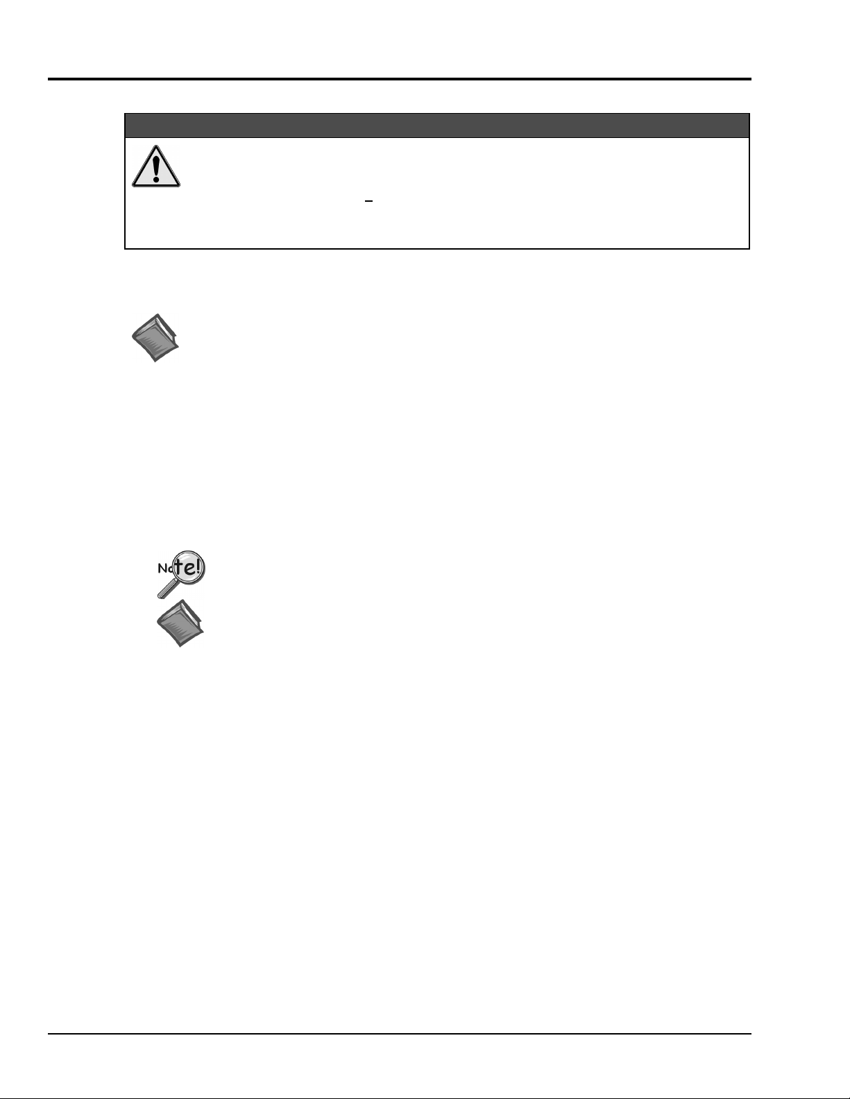
WaveView Configuration Window
In the WaveView Configuration main window (see figure) the following columns are
important in regard to filters.
LPF Mode – You can click on a cell in the LPF Mode column to make the cell “active,” and
then change its setting. Options for WBK14’s LPF Mode are:
(a) On – turns the Low-Pass Filter on
(b) External – selects an external filter
(c) Bypass – bypasses the low-pass filter
LPF Cutoff – the cells in this column are used to set the Low-Pass Filter cutoff frequency.
HPF Cutoff – the cells in this column are used to set the High-Pass Filter cutoff frequency.
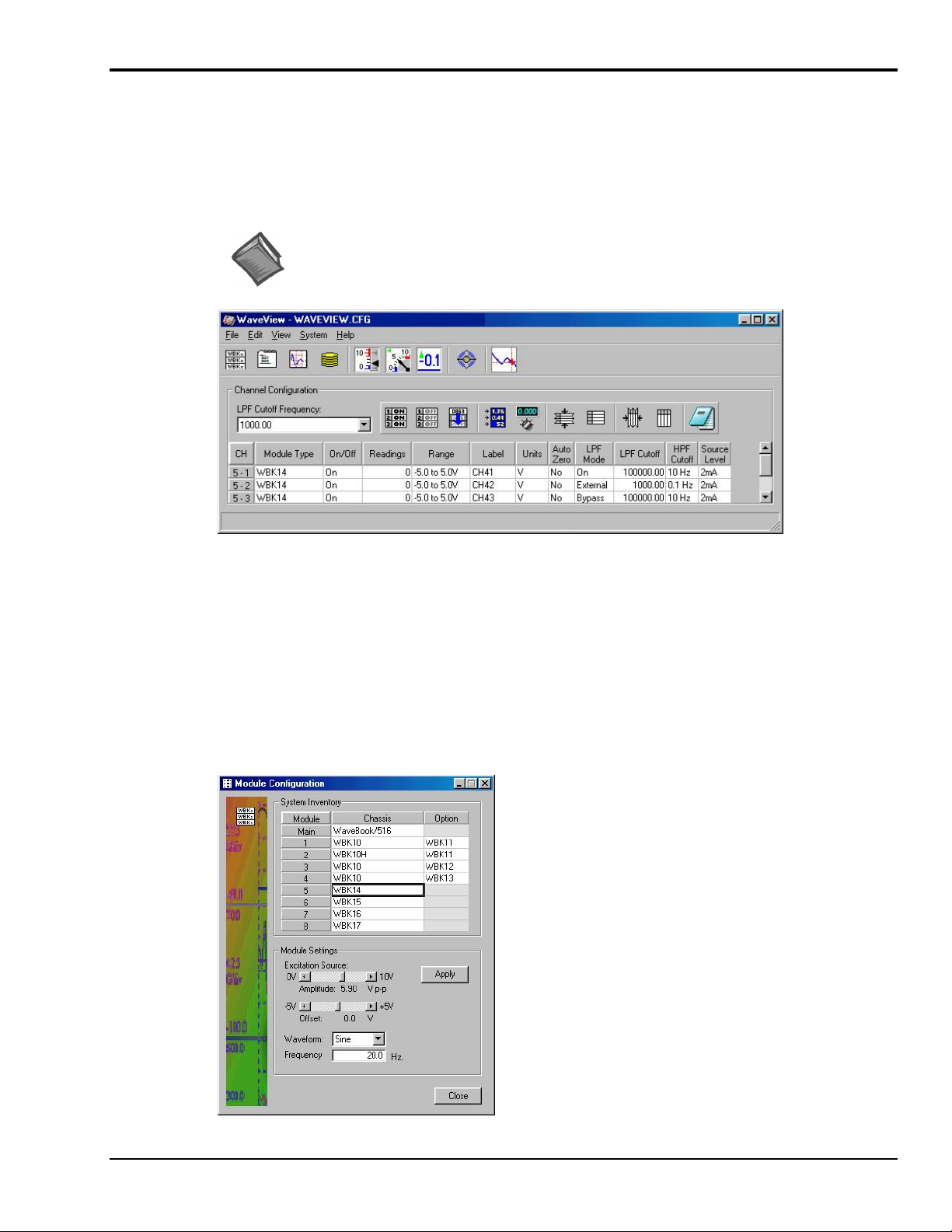
For WBK14 applications, the Module
Configuration window allows you to set
the excitation source in regard to:
amplitude
offset
waveform (Sine, or Random)
frequency
The Module Configuration window can
be accessed from the View pull-down
menu or by use of the first toolbar button
(located just below the File pull-down
menu).
Module Configuration Window
WBK14, Dynamic Signal Input Module
988396
WBK14, pg. 5
Page 30
Using Accelerometers with WBK14
(
)
Overview
A low-impedance piezoelectric accelerometer consists of a piezoelectric crystal and an electronic amplifier.
When stretched or compressed, the two crystal surfaces develop a charge variation that is related to the
amount of stress, shock, or vibration on the crystal. The amplifier outputs a corresponding signal and
transforms the sensor’s high impedance to a lower output impedance of a few hundred ohms. Note that, in
addition to acceleration, these sensors can also measure pressure and force.
The circuit requires only two wires (coax or twisted pair) to transmit both power and signal. At low
impedance, the system is insensitive to external or “triboelectric” cable noise. Cable length does not affect
sensitivity.
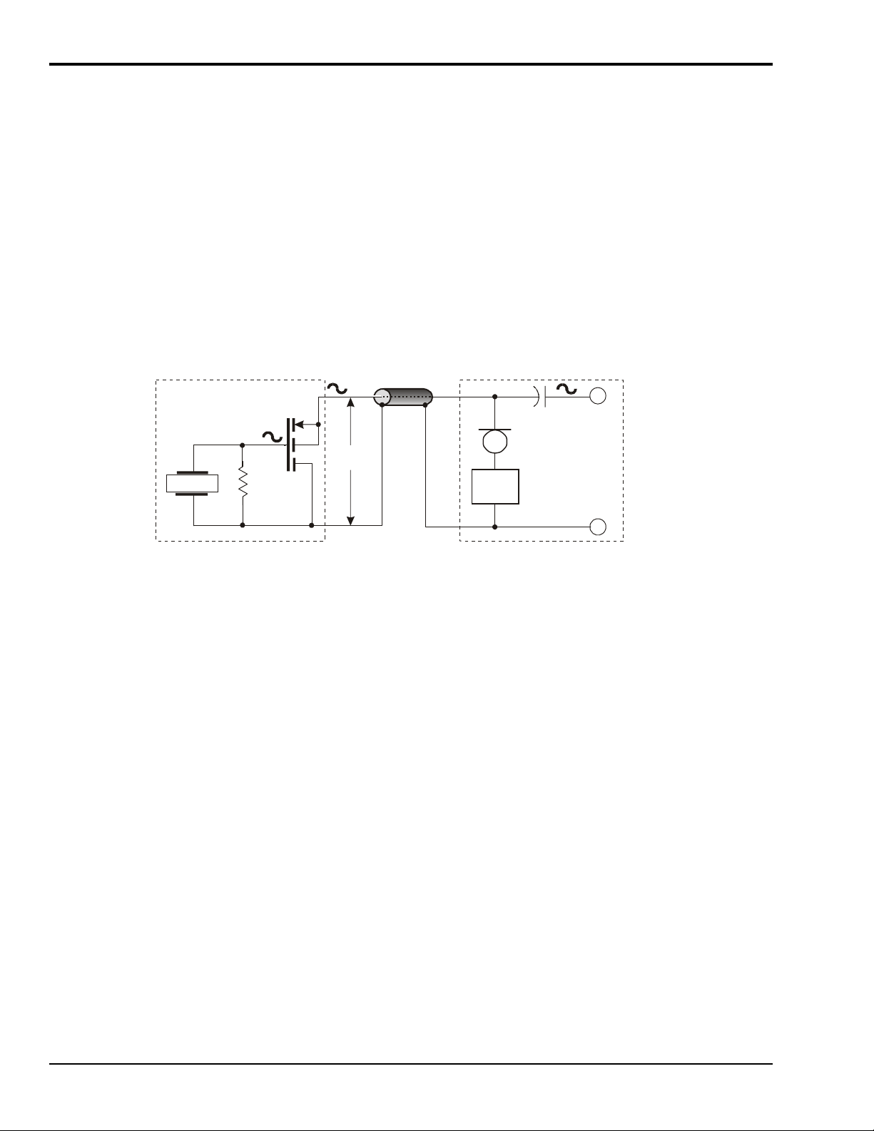
The following figure shows a simple sensor-WBK14 connection. The voltage developed across R is
applied to the gate of the MOSFET. The MOSFET is powered from a constant current source of 2 or 4 mA
and 27 volts.
Sensor to WBK14
Coaxial Cable
MOSFET
Bias
Vol tage
Sensor
R
Accelerometer Circuit
Crystal
The MOSFET circuit will bias off at approximately 12 V in the quiet state. As the system is excited,
voltage is developed across the crystal and applied to the gate of the MOSFET. This voltage will cause
linear variation in the impedance of the MOSFET and a proportional change in bias voltage. This voltage
change will be coupled to the WBK14 input amplifier through the capacitor C. The value of R and the
internal capacitance of the piezoelectric crystal control the low frequency corner. Units weighing only a
few grams can provide high level outputs up to 1 V/g with response to frequencies below 1 Hz.
Accelerometer Specification Parameters
Noise in Accelerometers
The noise floor or resolution specifies lowest discernible amplitude (minimum “g”) that can be measured.
There are two main sources of noise as follows:
• Noise from the crystal and microcircuit inside the accelerometer. Some types of crystals, such as
quartz, are inherently more noisy than others. A good noise floor is 10 to 20 µV.
-
+
30 VDC
Power
C
Constant
Current
2 or 4 mA
WBK14
Amplifier
Input
GND
• Noise from electrical activity on the mounting surface. Since the signal from the accelerometer is a
voltage, 60 Hz or other voltages (ground loop, etc) can interfere with the signal. The best protection is
to electrically isolate the accelerometer.
Sensitivity
The sensitivity of an accelerometer is defined as its output voltage per unit input of motion. The unit of
motion used is “g.” One “g” is equal to the gravitational acceleration at the Earth’s surface, which is
32.2 ft/(sec)(sec) or 981 cm/(sec)(sec). The output is usually specified in millivolts per “g” (mV/g).
Sensitivity is usually specified under defined conditions such as frequency, testing levels, and temperature.
An example: 100 mV/g at a frequency of 100 Hz, level +1 g, at 72°F. Note that, although a sensor may
have a “typical” sensitivity of 100 mV/g, its actual sensitivity could range from 95 to 105 mV/g (when
checked under stated conditions). Manufacturers usually provide sensor calibration values.
WBK14, pg. 6
988396
WBK14, Dynamic Signal Input Module
Page 31

Transverse Sensitivity - An accelerometer is designed to have one major axis of sensitivity, usually
perpendicular to the base and co-linear with its major cylindrical axis. The output caused by the motion
perpendicular to the sensing axis is called transverse sensitivity. This value varies with angle and frequency
and typically is less than 5% of the basic sensitivity.
Base-Strain Sensitivity - An accelerometer’s base-strain sensitivity is the output caused by a deformation
of the base, due to bending in the mounting structure. In measurements on large structures with low natural
frequencies, significant bending may occur. Units with low base-strain sensitivity should be selected.
Inserting a washer (smaller in diameter than the accelerometer base) under the base reduces contact surface
area; and can substantially reduce the effects of base-strain. Note that this technique lowers the usable
upper frequency range.
Acoustic Sensitivity - High-level acoustic noise can induce outputs unrelated to vibration input. In general,
the effect diminishes as the accelerometer mass increases. Use of a light, foam-rubber boot may reduce this
effect.
Frequency Response
An accelerometer’s frequency response is the ratio of the sensitivity measured at frequency (f) to the basic
sensitivity measured at 100 Hz. This response is usually obtained at a constant acceleration level, typically
1 g or 10 g. Convention defines the usable range of an accelerometer as the frequency band in which the
sensitivity remains within 5% of the basic sensitivity. Measurements can be made outside these limits if
corrections are applied. Care should be taken at higher frequencies because mounting conditions greatly
affect the frequency range (see Mounting Effects, in upcoming text).
Dynamic Range
The dynamic measurement range is the ratio of the maximum signal (for a given distortion level) to the
minimum detectable signal (for a given signal-to-noise ratio). The dynamic range is determined by several
factors such as sensitivity, bias voltage level, power supply voltage, and noise floor.
Bias Level
Under normal operation, a bias voltage appears from the output signal lead to ground. There are two basic
MOSFET configurations commonly used. One exhibits a 7-8 V bias and the second a 9-12 V bias.
Operation of the two circuits is identical except for the available signal swing. The low-voltage version
typically exhibits 5-10 µVrms versus 10-20 µVrms for the high voltage.
Thermal Shock - Temperature Transients
Piezoelectric accelerometers exhibit a transient output that is a function of a temperature’s “rate-of-change.”
This “thermal shock” is usually expressed in g/°C and is related to:
•
Non-uniform mechanical stresses set up in the accelerometer structure.
•
A pyroelectric effect in piezoelectric materials—an electrical charge is produced by the
temperature gradient across the crystal.
This quasi-static effect produces a low-frequency voltage input to the MOSFET amplifier. This voltage is
usually well below the low-frequency corner, but the effect can reduce the peak clipping level and cause
loss of data. This effect does not affect the accelerometer’s basic sensitivity or the data unless the thermal
shift in the operation bias level results in clipping. Where drastic thermal shifts are expected, use 12 V bias
models. The effect’s severity is related to the mass of the accelerometer. In 100 mV/g industrial units, the
effect is usually negligible. Using rubber thermal boots can reduce the effect significantly.
Overload Recovery
Recovery time from clipping due to over-ranging is typically less than 1 ms. Recoveries from quasi-static
overloads that generate high DC bias shifts are controlled by the accelerometer input RC time constant that
is fixed during manufacture.
Power Supply Effects
The nominal power supply voltage recommended by most manufacturers is 15 to 24 V. Units may be used
with voltages up to 28 volts. Sensitivity variations caused by voltage change is typically 0.05%/volt.
Power supply ripple should be less than 1 mVrms.
WBK14, Dynamic Signal Input Module
988396
WBK14, pg. 7
Page 32

Connector
This parameter specifies the connector type and size (4-48, 6-40, 10-32 coaxial etc) and the location on the
sensor, that is, top or side (usually on the hex base). Where there is no connector on the sensor, an integral
cable is specified with the length and the connector, that is, integral 6-ft to 10-32.
Electrical Grounding
Case-Grounded Design
In case-grounded designs, the common lead on the internal impedance matching electronics is tied to the
accelerometer case. The accelerometer base/stud assembly forms the signal common and electrically
connects to the shell of the output connector. Case-grounded accelerometers are connected electrically to
any conductive surface on which they are mounted. When these units are used, take care to avoid errors
due to ground noise.
Isolated-Base Design
To prevent ground noise error many accelerometers have base-isolated design. The outer case/base of the
accelerometer is isolated electrically off ground by means of an isolation stud insert. The proprietary
material used to form the isolation provides strength and stiffness to preserve high-frequency performance.
Cable Driving
Operation over long cables is a concern with all types of sensors. Concerns involve cost, frequency
response, noise, ground loops, and distortion caused by insufficient current available to drive the cable
capacitance.
The cost of long cables can be reduced by coupling a short (1 m) adapter cable from the accelerometer to a
long low-cost cable like RG-58U or RG-62U with BNC connectors. Since cable failure tends to occur at
the accelerometer connection where the vibration is the greatest, only the short adapter cable would need
replacement.
Capacitive loading in long cables acts like a low-pass, second-order filter and can attenuate or amplify highfrequency signals depending on the output impedance of the accelerometer electronics. Generally this is not
a problem with low-frequency vibration (10 Hz to 2000 Hz). For measurements above 2000 Hz and cables
longer than 100 ft, the possibility of high-frequency amplification or attenuation should be considered.
The WBK14 constant-current source provides 2 or 4 mA to integral electronics. Use the higher current
setting for long cables, high peak voltages, and high signal frequencies.
The maximum frequency that can be transmitted over a given length of cable is a function of both the cable
capacitance and the ratio of the maximum peak signal voltage to the current available from the constant
current source:
Drive Current
(mA)
2 10 185 kHz 37 kHz
2 100 18.5 kHz 3.7 kHz
2 1000 1.85 kHz 370 Hz
4 10 550 kHz 110 kHz
4 100 55 kHz 11 kHz
4 1000 5.5 kHz 1.1 kHz
Cable Length
@30 pF/ft (Ft)
Frequency Response to 5% of
Maximum Output Signal Amplitude
± 1 V ± 5 V
Where:
f
K
V
2
C
π
Icc Ib=−
WBK14, pg. 8
f = Maximum frequency in Hz
K = 3.45 ×10
and a factor to allow cable capacitance to charge to 95% of the final charge.
C = Cable capacitance in picoFarads
V = Maximum peak measured voltage from sensor in volts
Icc = Constant current from current source in mA
Ib = Current required to bias the internal electronics, typically 1 mA
9
. K is the scale factor to convert Farads to picoFarads and Amperes to milliAmperes
988396
WBK14, Dynamic Signal Input Module
Page 33

WBK14 – Specifications
Name/Function: WBK14, 8-Channel Dynamic Signal Conditioning Module
Connectors
Channels
Gain Ranges
Power Consumption:
Input Power Range:
Operating Temperature:
Storage Temperature:
Dimensions:
Weight:
ICP Current Source:
Output Impedance:
Compliance:
Current Levels:
Coupling :
10 Hz High-Pass Filter - Input Impedance:
0.1 Hz High-Pass Filter - Input Impedance:
Input Ranges:
Anti-Aliasing Low-Pass Filter:
Excitation Source:
Sine:
Frequency:
Distortion:
Amplitude:
Steps:
Random:
Spectral Distribution:
Amplitude Distribution:
Bandwidth:
RMS level:
External Clock:
Digital:
Sine:
: BNC connector, mates with expansion signal input on the WaveBook/512, /512A, /516, /516A, or /516E.
Two 15-pin connectors, mate with expansion signal control on the WaveBook; signals via 1 BNC per channel
: 8
: ×1, 2, 5, 10, 20, 50, 100
15 Watts typical
10 to 30 VDC
0°C to 70°C
216 mm wide × 279 mm long × 35 mm high (8.5” × 11” × 1.375”)
1.32 kg (2.9 lb)
> 1.0 MΩ @ 20 kHz
27 V
2 & 4 mA
AC
±5.0 V, ±2.5 V, ±1.0 V, ±500 mV, ±250 mV, ±100 mV, ±50 mV
Accuracy
Frequency Span:
Frequency Settings:
Dynamic Range @ 1 kHz:
THD @ 1 kHz
Amplitude Matching:
Phase Matching:
Max. Output Voltage:
Max. Output Current:
DC Output:
> 500 mV peak
: ±0.5 dB at the pass-band center
: 70 dB
± 5 V
20 Hz to 100 kHz
< 0.1%
± 5 V
256
20 Hz to 100 kHz
Adjustable in binary steps
TTL levels
0°C to 50°C
590K
10 MΩ
30 Hz to 100 kHz
300 kHz / N; N = 3,4,...10000
69 dB
± 0.1 dB
± 2°
± 10 V
10 mA
White, Band-limited
Gaussian
WBK14, Dynamic Signal Input Module
988396
WBK14, pg. 9
Page 34

WBK15
Description
5B Isolated Signal-Conditioning Module
Description …… 1
Hardware Setup …… 2
Configuration …… 2
Connection …… 3
Power …… 4
Safety Concerns …… 4
Using Fastener Panels to Stack Modules …… 4
Software Setup …… 5
WBK15 – Specifications …… 7
The WBK15 module can accommodate eight 5B isolated-input signal-conditioning modules for use with the
WaveBook. The WaveBook can accommodate 8 WBK15s for a maximum of 64 expansion channels. The
WaveBook scans WBK15’s channels at the same 1 µs/channel rate that it scans all WBK analog inputs,
allowing it to measure all channels of a fully configured 72-channel system in 72 µs.
Other features of WBK15 include:
• Built-in power supply that operates from 10 to 30 VDC and can power a full complement of 5B
modules (even with bridge excitation).
• Removable, plug-in screw-terminal blocks for convenient connection of 5B modules.
•
On-board cold-junction sensing for thermocouple 5B modules.
•
For each 5B module, 1500 V isolation from the system and from other channels.
Current-Sense
Resistor
5.000 V
Buffered
5B
Low-
Module
Pass
Socket
Filter
#1
Input
Terminal
Block
Channel 1
Channels 2-8 identical
DC Power
Input &
Expansion
+V
Cold
Junction
Sensor
GND
DIN-5
Power
Switch
CH1
CH2
CH3
CH4
CH5
CH6
CH7
CH8
+15 V
Filters
Isolated
+5, ±15 VDC
Power
Supply
Channel
Selection
MUX
Internal Jumpers
-15 V
+5 V
WBK15 Block Diagram
Reference
Bipolar
Offset
Amp
Buffer
Amp
Control
DAC
µP &
Control Logic
EEPROM
Output
MUX
Status
LEDs
BNC
N
N
Analog
Output to
Wave Book
Expansion
Control
From
WaveBo ok
WBK15, 5B Isolated Signal Conditioning Module
988396
WBK15, pg. 1
Page 35

Hardware Setup
Configuration
The next figure shows the board layout within a WBK15. Note the channel-number layout for the 5B
modules and the location for plug-in current-sense resistors.
Only current-input type modules require the plug-in resistors.
The plug-in resistors must be removed for all other module types.
Rear Panel
Front Panel - signal inputs from 8 channels
BNC
Expansion
Signal Out
CHANNEL 1
R10
ch 2
CHANNEL 2 CHANNEL 4
ch 1
BNC
Expansion
Signal In
R5
ch 1
ch 2
ch 4
DB15
Expansion
Control Out
CHANNEL 3
R16 R13
ch 3
DB15
Expansion
Control In
CHANNEL 5
R20
ch 6
ch 3
CHANNEL 6
ch 4 ch 5 ch 6
WBK15 Board Layout
R18
DIN5
Power
Out
ch 8
ch 5
CHANNEL 7
R22
CHANNEL 8
ch 7
DIN5
Power
In
Fuse
R23
ch 8
Screw-terminal
Signal Plug
ON/OFF
Switch
ch 7
Status
LEDs
WBK15, pg. 2
Installation of 5B Modules
WARNING
WARNING
WARNINGWARNING
Electric shock hazard! Turn off power to WBK15 and all connected modules and
devices before inserting or removing modules. Failure to do so could lead to injury or
death due to electric shock.
CAUTION
CAUTION
CAUTIONCAUTION
Handle the 5B module carefully while inserting pins into the daughterboard. Do not
over-tighten mounting screw.
The 5B modules plug into a daughterboard (×2) on WBK15’s motherboard. Rubber bumpers on one side
and a tilted daughterboard allow the module to rest at a 5° angle to facilitate insertion and removal. The
adjacent daughterboard has a cut-a-way to allow room for a screwdriver (see figure).
988396
WBK15, 5B Isolated Signal Conditioning Module
Page 36

Connection
Screwdriver
5°angle to
facilitate installation
Rubber Rest
5B Module
5B Module
WBK15 Main Board
5B Module Insertion/Removal
WARNING
WARNING
WARNINGWARNING
5B Pins
(×14)
Mounting Screw
Daughterboard
Screw
Receptacle
Pin (×14)
Receptacles
Electric shock hazard! De-energize circuits connected to WBK15 before changing the
wiring or configuration. Failure to do so could lead to injury or death due to electric
shock.
Signals are connected by screw-terminal signal plugs that plug into the 4-pin jacks on WBK15’s front panel
(see figure).
+EXC
-
-EXC
+
-EXC Negative excitation output - only used on strain-gage type modules
- Negative signal input
+ Positive signal input
+EXC Positive excitation output - only used on strain-gage type modules
Signal Connection Jacks (per channel)
Input signals (and excitation leads) must be wired to the plug-in terminal blocks. Eight 4-terminal blocks
accept up to 8 inputs.
Terminal blocks are connected internally to their corresponding signal conditioning module. The terminal
blocks accept up to 14-gage wire into quick-connect screw terminals. Each type of input signal or
transducer (such as a thermocouple or strain gage) should be wired to its terminal block as shown in the
figure below. Wiring is shown for RTDs, thermocouples, 20mA circuits, mV/V connections, and for fulland half-bridge strain gages.
SIG H
SIG L
+Vin
-Vin-EXC
Thermocouple
Connection
+EXC
4-Wire
+
_
Full-Bridge Strain-Gage Connection
+EXC+Vin-Vin-EXC
mV and V Connection
-Vin
+EXC+Vin-Vin-EXC
+Vin
3-Wire2-Wire
+Vin
-Vin-EXC
RTD Connection
+EXC
Half-Bridge
Strain-Gage Connection
Typical Signal Connections
WBK15, 5B Isolated Signal Conditioning Module
-Vin-EXC
988396
+Vin
+EXC
-EXC
4-20 mA
Connection
+EXC
AC1362
20 Ohm
Plug-In Resistor
(SC-AC-1362)
On-Board Socket
WBK15, pg. 3
Page 37

Power
Like the WaveBook, WBK15 contains an internal power supply. The unit can be powered by the included
AC power adapter or any 10 to 30 VDC source, such as a 12 V car battery. For portable or field
applications, WBK15 and the WaveBook can be powered by the DBK30A rechargeable battery module or
DBK34 vehicle UPS module. The supply input is fully isolated from the measurement system. If the fuse
requires replacement, it is a 2 A fuse (Littelfuse #251002).
Safety Concerns
WBK15 is specified for 1500 VDC isolation in a normal environment free from conductive pollutants and
condensation. The 1500 VDC rating requires a proper earth ground connection to the chassis and treatment
of adjacent inputs as potentially hazardous. CE-marked units used in the European community are rated at
600 VDC isolation. The 600 VDC CE isolation specification is based on a double insulation requirement,
and no earth ground is required.
Prior to daisy-chaining from one module’s power connector to another, be sure to
compute the power consumption for the entire system. Some modules may need
independent power adapters. The WaveBook manual’s chapter entitled, System Setup
and Power Options contains detailed information regarding power supply issues.
WARNING
WARNING
WARNINGWARNING
Shock Hazard! Voltages above 50 Vrms AC and voltages above 100 VDC are
considered hazardous. Safety precautions are required when 5B modules are used in
situations that require high-voltage isolation from the rest of the system. Failure to
practice electrical safety precautions could lead to injury or death.
Input cables must be rated for the isolation potential in use. Line voltage ratings are much lower than the
DC isolation values specified due to transients that occur on power lines. Never open the lid unless all
inputs with potentially hazardous voltages are removed. The lid must be securely screwed on during use.
Some things to remember:
• Before closing up an open WBK15, ensure no foreign objects are inside.
• Properly tighten all chassis screws before system use.
• Properly tighten the screw that retains the 5B module.
•
Never plug in or unplug potentially hazardous connections with power applied to any
connected equipment.
• Never attempt to change 5B modules or open the lid with power applied to the WBK15. You
could short out internally exposed circuits and cause personal injury or equipment damage.
Reference Note:
Refer to the System Setup and Power Options chapter of the WaveBook User’s Manual for
detailed information regarding the power aspects of WaveBook systems.
Using Fastener Panels to Stack Modules
For convenient mounting, the WBK15 has the same footprint as other WBK modules and WaveBooks.
Fastener panels (splice plates) provide a means for stacking WaveBooks and modules. Screw-on handles
are available for portable applications.
WBK15, pg. 4
Reference Note:
For an illustration pertaining to mounting modules with fastener panels refer to the introduction
of this manual.
When using WBK17 modules in conjunction with other WBK modules, the WBK17
modules must be located closest to the WaveBook/516 (or /516A), due to the CA-217
cable length. The order of the other WBK modules does not matter.
988396
WBK15, 5B Isolated Signal Conditioning Module
Page 38

Software Setup
You will need to set several parameters so WaveView can best meet your application requirements.
For detailed WaveView information, refer to the WaveView Document PDF.
After the 5B module type is identified, WaveView figures out the m and b (of the mx+b equation) for
proper engineering units scaling. An example of the mx + b equation follows shortly.
PDF Note:
Fastener panels will partially block the vents on WBK16, WaveBook/516, and
WaveBook/516A when stacked. This partial blocking of vents does not jeopardize the
cooling process.
Reference Note:
➣
For detailed WaveView information, refer to the
➣
The API does not contain functions specific to WBK15. Refer to related material in the
WaveView Document P
DF.
Programmer’s Manual (p/n 1008-0901) as needed.
During software installation, Adobe
®
PDF versions of user manuals automatically install onto
your hard drive as a part of product support. The default location is in the Programs group,
which can be accessed from the Windows Desktop. Refer to the PDF documentation for details
regarding both hardware and software. Note that you can also access PDF documents directly
from the data acquisition CD via the <View PDFs> button on the CD’s opening screen.
WaveView Configuration Main Window
mX +b, an Example
Customize Engineering Units
The
dialog box can be
accessed via the WaveView Configuration main
window
by activating the Units cell [for the desired
channel], then clicking to select mX+b.
From the Customize Engineering Units dialog box
(see figure at right), you can enter values for m and b
components of the equation that will be applied to
the data. There is also an entry field that allows you
to enter a label for the new units that may result from
the mX+b calculation.
An example of mX + b equation use follows.
WBK15, 5B Isolated Signal Conditioning Module
988396
WBK15, pg. 5
Page 39

Engineering Units Conversion Using mx + b
Most of our data acquisition products allow the user to convert a raw signal input (for example, one that is
in volts) to a value that is in engineering units (for example, pressure in psi). The products accomplish this
by allowing the user to enter scale and offset numbers for each input channel, using the software associated
with the product. Then the software uses these numbers to convert the raw signals into engineering units
using the following “mx + b” equation:
Engineering Units = m(Raw Signal) + b (1)
The user must, however, determine the proper values of scale (m) and offset (b) for the application in
question. To do the calculation, the user needs to identify two known values: (1) the raw signal values, and
(2) the engineering units that correspond to the raw signal values. After this, the scale and offset parameters
can be calculated by solving two equations for the two unknowns. This method is made clear by the
following example.
Example
An engineer has a pressure transducer that produces a voltage output of 10.5 volts when the measured
pressure is 3200 psi. The same transducer produces an output of 0.5 volt when the pressure is 0 psi.
Knowing these facts, m and b are calculated as follows.
A - Write a pair of equations, representing the two known points:
3200 = m(10.5) + b (2)
0 = m(0.5) + b (3)
B - Solve for m by first subtracting each element in equation (3) from equation (2):
3200 - 0 = m(10.5 – 0.5) + (b - b)(4)
Simplifying gives you:
This means:
m = 320 (6)
C - Substitute the value for m into equation (3) to determine the value for b:
3200 = m(10) (5)
0 = 320 (0.5) + b (7)
: b = - 160 (8)
So
Now it is possible to rewrite the general equation (1) using the specific values for m and b that we just
determined:
Engineering Units = 320(Raw Signal) - 160 (9)
The user can then enter the values of m and b into the appropriate location using the facilities provided by
compatible data acquisition software, for example: WaveView, DaqView, Personal DaqView, LogView,
and TempView. The software uses equation (9) to calculate signal values in engineering units from that
point on.
WBK15, pg. 6
988396
WBK15, 5B Isolated Signal Conditioning Module
Page 40

WBK15 – Specifications
Name/Function: WBK15 Multi-Purpose Isolated Signal Conditioning Module
Connectors: 2 BNC connectors, mate with expansion signal input on the WaveBook/512, /512A, /516,
/516A, /516E; two 15-pin connectors, mate with the WaveBook’s Expansion Signal Control
Module Capacity: Eight 5B modules (optional) See latest catalog or contact your sales representative in
Input Connections
Power Requirements
With 8 thermocouple-type modules: 12 VDC @ 0.25 A, 15 VDC @ 0.20 A, 18 VDC @ 0.2 A
With 8 strain-gage-type modules: 12 VDC @ 0.95 A, 15 VDC @ 0.75 A, 18 VDC @ 0.65 A
Cold-Junction Sensor
Shunt-Resistor Socket: One per channel for current loop inputs
Isolation
Signal Inputs to System
Input Channel-to-Channel: 1500 VDC (600 VDC for CE compliance)
Power Supply to System
Dimensions: 221 mm × 285 mm × 36 mm (8.5” × 11” × 1.375”)
: 1.8 kg (4 lb) [with no modules installed]
Weight
: Removable 4-terminal plugs (Weidmuller type BL4, PN 12593.6,
regard to the types of 5B Modules available for your application.
or type BLTOP4, PN 13360.6)
: 10 to 30 VDC, or 120 VAC with included adapter
: Standard per channel
: 1500 VDC (600 VDC for CE compliance)
: 50 VDC
WBK15, 5B Isolated Signal Conditioning Module
988396
WBK15, pg. 7
Page 41

WBK16 Strain-Gage Module
Description.....................................................................................................1
Excitation Connection...................................................................................6
Low-Pass Filter Customization....................................................................7
Configuration Diagrams................................................................................8
Connecting to the DB9 Channel Input Connector ...................................12
CA-177 Strain-Gage Cable.................................................................................12
CN-189, DB9 Adapter Option .............................................................................13
Using the WBK16/LC Load Cell Shunt Cal Option...................................15
Using the CN-115-1 User-Configurable Plug-In Card Option..................19
Software Setup ............................................................................................22
Sensor Calibration.......................................................................................22
The Five Methods of Sensor Calibration.............................................................29
2 Point Manual Calibration..................................................................................30
2 Point Auto Calibration......................................................................................30
Shunt (Internal Shunt) Calibration.......................................................................31
External Shunt Calibration (2 Pt Shunt)..............................................................32
Name Plate Calibration.......................................................................................33
Changing Low-Pass Filter Displays ..........................................................35
WBK16 – User Tips......................................................................................36
WBK16 – Specifications..............................................................................38
Description
The WBK16 is an 8-channel strain-gage signal-conditioning module for the WaveBook system. Up to
eight of these modules (64 channels) can be accommodated by a WaveBook and scanned at 1 µs/channel.
Almost all bridge configurations are supported via a bridge-completion network and software. High-gain
differential-amplifier applications are also supported. Software controls bridge configuration, gain, offset,
excitation voltage, polarity, filtering, and the calibration p rocess.
Refer to the following block diagram as needed while reading this section.
WBK16 Block Diagram
WBK16, Strain-Gage Module 949794 WBK16, pg. 1
Page 42

Channel Selection
The eight independent channels are routed to the Channel Selection MUX (multiplexer) for ou tput to the
WaveBook through the Analog Interface. The Digital Interface controls the channel-scanning process and
allows digital configuration of all channels through the WaveBook's Serial Control Bus.
Excitation Source
Excitation power is programmable from a dual source—channels 1 to 4 from one source and channels 5 to
8 from another source. Each channel has a separate regulator with a fold-back current limiter. Up to 85 mA
is provided at 10 V out, decreasing to 30 mA when shorted. This is sufficient current to operate 120 Ω
gages at any voltage. Programmable output voltages of 0, 0.5, 1, 2, 5, and 10 volts are available. Remotesense inputs are provided and should be connected at the strain gage for best accuracy. If they are not used,
they need to be jumpered to the excitation output at the connector. The remote-sense inputs are fully
differential, and may even be connected across the completion resistor to form a constant-current linearized
quarter-bridge configuration.
Bridge Configuration
The strain gage is connected to the amplifiers through the Bridge Completion and Shunt Cal Network. This
network consists of user installed resistors for bridge completion. Several combinations of resistors and
three different shunt values may be installed simultaneously. External connector tie points and the
programmable Input Configuration & Cal MUX determine the actual configuration in use. Once the
network is fully configured, most bridge configurations and resistances can be accommodated without reopening the box. The shunt resistors allow each bridge to be put into a known imbalance condition for
setting or verifying channel calibration. Shunt calibration allows a full-scale gain to be set without
physically loading the bridge.
Amplifiers
Each channel has an amplifier consisting of two series-connected stages. The instrumentation amplifier
(PGIA) has programmable gains of x1, x10, x100, and x1000. A programmable gain amplifier (PGA)
follows, with a gain range of 1 to 20 in 28% steps. This results in a combined programmable gain range
of 1 to 20,000 in 28% steps. The optimal gain is automatically determined during the gage calibration
process.
Offset Source
A low-drift, programmable offset voltage source with a range of ±3.0 V is used to balance the bridge
during the gage calibration process. This offset source will correct for mismatched bridge resistors and
quiescent loads of the strain gage and still retain the full dyn amic range.
Auto-zero removes the static portion of the strain load and zeros the input to compensate for any input
drift. Because this is done electronically, zeroing is independent of the user. Simply select the channels
that are to be auto-zeroed and the WBK16 will complete the task automatically.
Filters
Two different 4-pole Butterworth low-pass noise rejection filters are selectable through software by the
Output Selection MUX. The filters have a nominal cutoff frequency of 10 Hz and 1 kHz. Four SIP resistor
networks allow you to determine two cutoff frequencies. See the Hardware Configuration section for
details. If full bandwidth is required, a filter bypass mode is software selectable.
Output Selection
An AC coupling circuit with a 1-Hz cutoff frequency can be software selected by the MUX. This MUX
can also select an Inverting Amplifier for proper output signal polarity. The Inverter avoids having to
rewire the gage if the polarity is reversed. Note that the Inverter option is not available for AC-coupling
modes.
WBK16, pg. 2 949794 WBK16, Strain-Gage Module
Page 43

Front & Rear Panels
A
C
WBK16’s front panel has the following connectors and indicators as shown:
The rear panel has the power switch and the following connectors as shown:
Power
WBK16 requires an input voltage between
+10 and +30 VDC. The DC source should
be filtered but not necessarily regulated.
The TR-40U AC power adapter is
recommended for AC line applications.
WBK16 may be powered with the supplied
AC adapter that plugs into any standard AC
wall outlet or from any isolated 10-30 VDC
source of at least 25 W (see figure). Before
plugging unit in, make sure the power
switch is in the “0” (OFF) position.
If you are using an AC power adapter, plug it into an AC outlet and attach the low voltage end to WBK16’s
DIN5 jack. If you are using another source of power, make sure leads are connected to the proper DIN5
terminals as shown in the figure.
• 8 DB-9 connectors for bridge input
• 3 LEDs to indicate system status (Active, Ready, Power)
• 2 5-pin DIN5 connectors for power input and power pass-through
• 1 DB-15M expansion control input connector
• 1 DB-15F expansion control output connector
• 2 BNC connectors for analog expansion in and out
A
Power
Source
Power
Switch
AC
Power
Adapter
Power Inpu t
Connectors
+V
10 to 30 VDC
+
GND
WBK16 Power C onnections
CTIVE
READY
POWER
WBK16 Rear Panel
CAUTION
Do not exceed the 5 amp maximum DC current limit of the POWER IN and POWER OUT
DIN connectors.
Internal DC to DC converters provide properly isolated and regulated +15V, +12V, and +5V from the single 10
to 30 VDC external source. Excitation power is derived from these internal converters. An internal replaceable
fuse rated at 4 A provides overload protection. For replacement, use a
Littelfuse #251004. Reversed input polarity is the usual cause of a blown fuse.
Reference Note:
The WBK16 fuse (Littelfuse #251004, rated at 4A) is located on the board, between the
Power Switch and the Power In connector.
WBK16, Strain-Gage Module
Reference Note:
For details on powering WaveBook systems, refer to the WaveBook manual chapter entitled
System Setup and Power Options.
949794 WBK16, pg. 3
Page 44

Stacking Modules
For convenient mounting, the WBK16 has the same footprint as other WBK modules and WaveBooks.
Corner brackets (protective ears) provide a means for stacking WaveBooks and modules. Screw-on
handles are available for portable applications.
Board Layout
The following figure shows the WBK16 board layout for locating user-accessible components. You may
need to refer to this figure to locate components referenced in the text. The jumper positions are not user
functions, and are only shown for reference in case they are dislodged.
When using WBK17 modules in conjunction with other WBK modules, the WBK17
modules must be located closest to the WaveBook/516 (or /516A), due to the CA-217
cable length. The order of the other WBK modules does not matter.
WBK16 Board Layout
Configuration options on WBK16 include:
• Customization of low-pass filter frequencies using resistor networks
• Bridge completion resistor installation
• Shunt calibration resistor installation
CAUTION
WBK16, pg. 4 949794 WBK16, Strain-Gage Module
Be careful to avoid component damage while WBK16 enclosure is open. Always
remove bridge completion headers (CN-115) from the unit before soldering resistors
in the headers.
Page 45

A fan draws and exhausts air through vents in the WBK16 enclosure. To maintain
sufficient cooling it is important to keep the fan and vents free of obstruction.
Bridge Applications
WBK16 can accommodate many different strain-gage configurations. All strain-gage bridge configurations
consist of a 4-element network of resistors. The quarter, half or full designation of a strain gage refers to
how many elements in the bridge are strain-variable. A quarter-bridge has 1 strain-variable element; a halfbridge has 2 strain-variable elements; and a full-bridge has 4 strain-variable elements.
Full-bridges generally have the highest output and best performance. Output signal polarity is determined
by whether the strain-variable resistance increases or decreases with load, where it is located in the bridge,
and how the amplifier inputs connect to it. Configuration polarity is not important in WBK16, due to an
internal software-selected inversion stage. This simplifies bridge configuration.
Each WBK16 channel has locations for five bridge-completion resistors. These BCR’s are fo r use with
quarter and half-bridge strain gages. The resistors make up the fixed values necessary to complete the
4-element bridge design.
A full-bridge gage requires no internal completion resistors, but they may still be installed for other
configurations in use. The additional resistors will be ignored when the software has selected full-bridge
mode. Both quarter- and half-bridge gages require an internal half-bridge consisting of header positions Rg
and Rh. The recommended minimum values are 0.1%, <5 PPM/°C drift, 1 KΩ, and 0.25-watt resistors.
Lower values will dissipate more power and add heat. Values >1KΩ will increase the amount of drift and
noise. The same value half-bridge resistors can be used for any resistance strain gage. This internal halfbridge will be automatically selected by the software when needed.
Internal 1 MΩ shunt resistors are used to avoid open circuits.
These resistors are not suitable for high-accuracy/low-noise applications.
A quarter-bridge gage additionally requires a resistor of equal
value to itself. Up to 3 different values may be installed
simultaneously in header positions Ra, Rc, Re. All of these
resistors are connected to the (-) excitation terminal. An external
jumper at the input connector determines which resistor is
utilized. Therefore, 3 different quarter-bridge values can be
supported without opening the enclosure. Each different value
bridge would simply have the jumper in a different location;
when the gage is plugged in, the proper resistor is then already
selected. Configurations with the completion resistor on the (+)
excitation are redundant, due to the internal inversion stage, and
not used.
The bridge-configuration figures in the following text show various strain-gage configurations divided into
4 groups: Full-bridge, half-bridge, quarter-bridge, and high-gain voltmeter. Many of these configurations
can coexist but are shown individually for clarity.
WBK16, Strain-Gage Module 949794 WBK16, pg. 5
Page 46

Excitation Connection
Remote sense inputs are provided for the excitation regulators. The excitation voltage will be most accurate
at points where remote sense lines are connected, preferably at the bridge (this is often referred to as a
6-wire connection). Long cables will reduce the voltage at the bridge, due to current flow and wire
resistance, if remote sense is not used.
If the 6-wire approach is not used, the remote sense inputs must be jumpered to the excitation
outputs at the input connector. Internal 1 MΩ resistors are also connected where the jumpers would be
located to prevent circuit discontinuities. These 1 MΩ resistors are not suitable for high-accuracy
excitation-voltage regulation.
3-wire quarter-bridge configurations do not benefit from external remote sense connections. The lead
resistance is actually a balanced part of the bridge. If the + remote sense input is connected to the + input
on a quarter-bridge, the voltage is regulated across the bridge completion resistor. This results in a
constant-current linearized quarter-bridge; otherwise quarter-bridges are not perfectly linear.
Shunt-Calibration Resistors. StrainBooks and WBK16s each provide three physical locations for internal
shunt-calibration resistors for each channel. Each shunt resistor is switched in from the EXCITATION (-)
to the IN (+) of the Instrumentation Amp by a FET switch to create a repeatable bridge imbalance. Internal
resistance of the circuit is about 1 kΩ; the exact amount is automatically accounted for in the software. The
software also allows selection of the three shunt resistors ( B, D, F ). An internal inversion stage insures
correct polarity during the shunt calibration process; which arm is shunted is therefore irrelevant. Header
positions Rb, Rd, Rf correspond to the software shunt resistor selections of B, D, F.
For any balanced bridge, a resistance value can be placed in parallel with one element to create a
predictable imbalance and output voltage. This shunt-resistance value can be calculated by the following
equation, where V
Example:
R
= R
Shunt
= 350 [ ( 10 / 4(0.020)) - 0.5 ] = 43,575Ω
R
Shunt
Configuring the Bridge Completion Resistor Modules. For each channel, the
board has a 2×8 resistor socket with rows designated A through H. The removable
adapter plugs are included for soldering in the resistors. Additional adapter plugs
are available for convenient changeover of alternate configurations. Resistor Ra is
located nearest the front panel.
Be careful to avoid component damage while the WBK16 enclosure is open. Always
remove bridge completion headers (adapter plugs) from the unit before soldering
resistors in the headers.
is the differential output voltage of the gage.
out
Bridge Arm
[ ( V
Excitation
/ 4 (V
)) - 0.5 ]
out
CAUTION
Solder resistor lead
into support fork.
o Half-bridge completion resistors consist of Rg and Rh.
o Quarter-bridge completion resistors consist of Ra, Rc, and Re.
o Shunt resistors consist of Rb, Rd, and Rf.
Inserting resistors directly into the socket makes an unreliable connection and
is not recommended. Remove the plug from the main board; then solder
resistors to the adapter plug as indicated. To avoid damaging the pin
alignment on the plug, solder with minimal heat. After soldering, the resistor
leads should be snipped off close to the support.
WBK16, pg. 6 949794 WBK16, Strain-Gage Module
Soldering Resistors to
Adapter Plug
Page 47

Reference Notes:
Schematics of various bridge configurations begin on page 8.
DB9 connector information, including use of the optional CN-189 adapter, is located
on page 12.
The WBK16/LC Load Cell Shunt Cal Internal Option is discussed on page 15.
The CN-115-1 User-Configurable Plug-In Card performs the same function as the
CN-115 Header Plug-in Option. CN-115-1 is discussed on page 19.
Low-Pass Filter Customization
Each StrainBook and WBK16 module has 68 kΩ 4-resistor SIP networks installed at the factory. These
networks result in a 10.9 Hz cutoff for filter A and a 1092 Hz cutoff for filter B. The 4-resistor SIP
networks are socketed and can be altered to the range of values in the table below. Individual resistors may
also be used but should be matched within 2%. Cutoff frequency accuracy is about ±5%.
If you change the filter nominal values, be sure to update the filter cutoff frequencies in
the WaveView software. This is discussed in the Chapter 4 section entitled Changing
Low-Pass Filter Displays.
Filter A Filter B
Resistance
in kΩ
470 1.58 33 22.5 470 158 33 2250
330 2.25 22 33.8 330 225 22 3375
220 3.38 15 49.5 220 338 15 4950
150 4.95 10 74.3 150 495 10 7425
100 7.43 8.2 90.5 100 743 8.2 9055
82 9.05 6.8 109 82 905 6.8 10919
68 10.9 4.7 158 68 1092 4.7 15798
47 15.8 3.3 225 47 1580 3.3 22500
Lower frequency filters, such as the 10-Hz filter provided, are generally used to reduce hig her frequency
noise. Some common sources of noise are: 50/60 Hz power line pickup on long cables, electromagnetic
interference (EMI) from nearby equipment, unwanted vibrations in the strain gage system itself, or at
higher gains the intrinsic thermal noise of the amplifiers. All information above the cutoff will also be lost
due to the filter’s function.
Frequency
in Hz
Resistance
in kΩ
Frequency
in Hz
Resistance
in kΩ
Frequency
in Hz
Resistance
in kΩ
Frequency
in Hz
The 1-kHz filter provided is typically used as an anti-aliasing filter, or for slight noise reduction while still
maintaining moderate bandwidth.
WBK16, Strain-Gage Module 949794 WBK16, pg. 7
Page 48

Configuration Diagrams
Full-Bridge Configurations
The full-bridge has four strain-variable elements and requires no bridge completion components. Quarter and
half-bridge resistors may be left installed. Any bridge resistance from 60 to 1000 ohms can be accommodated.
5
9
4
8
3
7
2
6
1
External
Bridge
External
Bridge
DB-9
Input
RARBRC
Full-Bridg e (+ ), An y Resistance from 60 to 1000 Ohm s
5
9
4
8
3
7
2
6
1
DB-9
Input
RARBRC
Full-Bridge (+), with Remote Sense
JN01
RDRERF
Internal Bridge Completion
JN01
RDRERF
Internal Bridge Completion
+Sense
+Excitation
RH
3
2
1
IA
In this connection, excitation voltage is
regulated at the connector. This
configuration should only be used for
short cable lengths. Output polarity may
be altered by interchanging the (+) and (-)
input or by selecting the software invert
function.
RG
Switches
accessed
through
software
-Excitation
-Sense
+Sense
+Excitation
RH
3
2
1
IA
In this connection, excitation voltage is
regulated at the strain gage.
This eliminates errors due to cable
losses and is the preferred connection
for longer cables.
RG
Switches
accessed
through
software
-Excitation
-Sense
5
9
4
8
3
7
2
6
1
External
Bridge
DB-9
Input
RARBRC
Internal Bridge Completion
RDRERF
Full-Bridge (+), with B, D, or F Shunt
WBK16, pg. 8
+Sense
+Excitation
RH
3
JN01
2
1
IA
The B, D, or F shunt resistor may be
Switches
accessed
through
software
RG
949794
WBK16, Strain-Gage Module
-Excitation
-Sense
software selected when installed as
shown. Output polarity during shunt
calibration will be automatically
corrected by software. The shunt resistor
value will typically be different for each
value of bridge resistance.
Page 49

Half-Bridge Configurations
The half-bridge has two strain-variable elements and requires two internal bridge completion resistors (BCRs).
Any bridge resistance from 60 to 1000 ohms can be accommodated for either the internal or external bridge.
RH
JN01
3
2
1
External
Bridge
9
8
7
6
DB-9
Input
5
4
3
2
1
RA
RB
Internal Bridge Completion
RCRDRERFRG
Half-Bri dge (+), Any Resistance from 60 to 10 00 O hm s,
B,D, or F Shunt
Switches
accessed
through
software
+Sense
+Excitation
IA
-Excitation
-Sense
In this connection, excitation voltage is
regulated at the connector.
This configuration should only be used
for short cable lengths.
Output polarity can be altered by
selecting the software invert function.
The B, D, or F shunt resistor may be
software selected. Output polarity during
shunt calibration will be automatically
BCR
H
BCR
G
Shunt
Shunt
F
E
Shunt
D
C
B
Shunt
A
corrected by software.
+Sense
+Excitation
RH
JN01
3
2
1
IA
In this connection, excitation voltage is
Switches
accessed
through
software
-Excitation
-Sense
regulated at the strain gage.
This is the preferred connection for
longer cables.
External
Bridge
5
9
4
8
3
7
2
6
1
DB-9
Input
RA
RB
RCRDRERFRG
Internal Bridge Completion
Half-Bridge (+), with Remote Sense
+Sense
+Excitation
RH
5
9
4
8
3
7
2
6
1
External
Bridge
DB-9
Input
RARBRCRDRERFRG
Internal Bridge Completion
3-W ire TC Half- B ridge, Softw are Invert & B, D, F Shunt Ava il able
JN01
3
2
1
IA
This occasionally utilized connection can
Switches
accessed
through
software
-Excitation
-Sense
be made as shown. Two resistors
normally reserved for quarter-bridge
completion must be used.
For compatibility with other
configurations, use of one of the above
two configurations is preferred over
this one.
WBK16, Strain-Gage Module 949794 WBK16, pg. 9
Page 50

Three-Wire Quarter-Bridge Configurations
The three-wire quarter-bridge has only one strain-variable element and requires three bridge completion resistors
(BCRs). The internal half-bridge may be any two matched values, but the remaining resistor must match the
external quarter-bridge value precisely. Three of these values may be installed simultaneously when connected
as shown below; the connector pins determine which resistor is used. With all three values installed, WBK16
can accommodate all three quarter-bridge values without changing the internal resistors.
+Sense
+Excitation
RH
JN01
3
2
1
IA
A 120-ohm resistor and its corresponding
Switches
accessed
through
software
-Excitation
-Sense
shunt value may be installed as shown.
External
Bridge
5
9
4
8
3
7
2
6
1
DB-9
Input
RARBRCRDRERFRG
Internal Bridge Completion
Thre e-Wire Quarter-Bridge (+),
Using RA (120-Ohm nom i na l ), B Shunt Resistor
+Sense
+Excitation
External
Bridge
External
Bridge
RH
9
8
7
6
DB-9
Input
5
4
3
2
1
RARBRCRDRERFRG
Internal Bridge Completion
JN01
3
2
1
Switches
accessed
through
software
Three-Wire Quarter-Bri dg e (+),
Using RC (350-Ohm nominal), D Shunt Resistor
9
8
7
6
DB-9
Input
5
4
3
2
1
RARBRCRDRE
Internal Bridge Completion
JN01
RF
3
2
1
Switche s
accessed
through
software
RG RH
Thre e- Wire Quarter- Bridge (+),
Using RE (1-KOhm no m inal), F Shunt Re sisto r
IA
-Excitation
-Sense
+Sense
+Excitation
IA
-Excitation
-Sense
A 350-ohm resistor and its corresponding
shunt value may be installed as shown.
A 1000-ohm (or other value) resistor and
its corresponding shunt value may be
installed as shown.
WBK16, pg. 10 949794 WBK16, Strain-Gage Module
Page 51

High-Gain Amplifier Configurations
WBK16s are useful as a programmable high-gain amplifier. No external bridge is used in these cases.
The inputs are fully differential.
Note: The differential inputs are not isolated inputs. Common mode voltage should not exceed ±10 V.
+Sense
+Excitation
RH
5
9
8
7
6
DB-9
Input
4
3
2
1
RA
RB
Internal Bridge Completion
RCRDRERFRG
External
Bridge
+
-
Univer sal High - G ai n A m p lifier In p ut , D ifferent ia l
JN01
3
2
1
IA
No pull-down resistors are required if the
Switches
accessed
through
software
-Excitation
-Sense
input signal ground is connected to Pin 1
as shown.
+Sense
+Excitation
JN01
3
2
1
IA
Switches
accessed
through
software
RG RH
-Excitation
-Sense
External
Bridge
5
9
8
7
6
DB-9
Input
4
3
2
1
RA
RBRCRDRERF
Internal Bridge Completion
+
-
Universal High-Gain Amplifier Input, Differential with Pull Downs
+Sense
+Excitation
RH
JN01
3
2
1
IA
Switche s
accessed
through
software
-Excitation
-Sense
External
Bridge
5
9
8
7
6
DB-9
Input
4
3
2
1
RA
RB
Internal Bridge Completion
RCRDRERFRG
+
Universal Hi gh-Gai n Am p li f ie r Input , Si ng l e - E nd e d
A floating input without a ground
reference, such as a battery, requires a
path for input bias currents. Pull-down
resistors of 1k to 10MΩ may be installed
as shown to provide this function.
A 10MΩ resistor would be suitable in
most cases.
These resistors are not compatible with
other bridge configurations.
If the (-) input is ground referenced, the
input is non-differential and pull-down
resistors are not required. A floating
source would still result in a truly
differential input.
WBK16, Strain-Gage Module 949794 WBK16, pg. 11
Page 52

Connecting to the DB9 Channel Input Connector
CAUTION
Remove the module from power and disconnect the unit from all externally
connected equipment prior to connecting cables, signal lines, and/or removing the
cover to install or remove components. Electric shock or damage to equipment can
result even under low-voltage conditions.
Take ESD precautions (packaging, proper handling, grounded wrist strap, etc.)
Use care to avoid touching board surfaces and onboard components. Only handle
boards by their edges (or ORBs, if applicable). Ensure boards do not come into
contact with foreign elements such as oils, water, and industrial particulate.
The figure shows the pinout of the DB-9 connector used for channels 1
through 8 located on the front panel. The strain gage will connect
directly to these pin sockets, unless the CN-189, DB9 Adapter option is
used. The CN-189 option is discussed in the following sub-section.
A quality cable (such as the CA-177 strain-gage cable) can improve performance of the system, especially
with long cable runs. Use cable with an overall shield connected to the DB9 metal shell. Twisted pair cable
with paired leads for signal input, excitation output, and remote sense input is also beneficial.
WBK16’s DB9 Pinout
The wires should be soldered to the DB9 to eliminate noise created by contact resistance variations. The
protective hoods should be installed over the 9-pin connectors during use to avoid draft-induced thermalelectric noise in the connector solder joints. Molded cables wider than 1.23 inches will not fit WBK16's
connector spacing.
CA-177 Strain-Gage Cable
Use cable with an overall shield connected to the DB9 metal shell. Twisted pair cable with paired leads for
signal input, excitation output, and remote sense input are also beneficial.
The wires should be soldered to the cable’s DB9 connector to eliminate noise created by contact resistance
variations. The protective hoods should be installed over the 9-pin connectors
during use to avoid draft-induced thermal-electric noise in the connector solder
joints.
Molded cables wider than 1.23 inches will not fit the DB9 connectors due to
available space between the unit’s connectors. Cable Pinout*
CA-177 Strain-Gage Cable Pinout* Cable CA-177 Specifications
DB9 Male End (P1) Unterminated End (P2)
Pin 1 Brown wire
Pin 2 Red wire
Pin 3 Orange wire
Pin 4 Yellow wire
Pin 5 Green wire
Pin 6 Blue wire
Pin 7 Purple wire
Pin 8 Black wire
Pin 9 White wire
Shell Drain wire ---
*Cable DB9 numbering is opposite of that found on the WBK16 to allow for correct pin mating.
P1 Cable End: DB9 male, assembled metal
hood with thumbscrews
(solder cup DB9).
P2 Cable End: Unterminated, blunt cut.
Cable Type: Belden 9614 or equivalent.
Wire Gauge: 24 AWG.
Outer Shield: Foil and 65% braid.
Number of Conductors: Nine (9) plus drain.
Dimensions: Length: 72" ± 4",
Connector width: 1.220" maximum
P1-to-P2 Pinout Specifications:
As indicated at left.
WBK16, pg. 12 949794 WBK16, Strain-Gage Module
Page 53

CN-189, DB9 Adapter Option
Remove the WBK16 from power and disconnect the unit from all externally
connected equipment prior to connecting cables, signal lines, and/or removing the
cover to install or remove components. Electric shock or damage to equipment can
result even under low-voltage conditions.
Take ESD precautions (packaging, proper handling, grounded wrist strap, etc.)
Use care to avoid touching board surfaces and onboard components. Only handle
boards by their edges (or ORBs, if applicable). Ensure boards do not come into
contact with foreign elements such as oils, water, and industrial particulate.
The CN-189 option consists of two 7-pad jumpers (P3 and P4), a DB9 connector, and a 9-slot screwterminal block. The adapter plugs into channel input DB9 connectors on StrainBooks and WBK16
expansion modules.
With use of the terminal block and appropriate shorting of jumper pads, the user can easily set up the
desired bridge configuration. A table indicating bridge types and the respective CN-189 jumper pad shorts
follows shortly. In some cases, the user may want to install a resistor at location R1. The electrical
relation of CN-189 components is shown in the following schematic.
Be careful to avoid component damage while the WBK16 module is open. Always
remove bridge completion headers (CN-115) from the unit before soldering resistors
in the headers.
CAUTION
CN-189 DB-9 Adapter Option
The CN-189 is intended for convenience and is not shielded. Higher signal quality will
be obtained with the use of shielded cables, such as the CA-177 strain gage cable.
WBK16, Strain-Gage Module 949794 WBK16, pg. 13
Page 54

CN-189 Schematic
CN-189 DB9 Adapter for WBK16, Configuration Table
Function P3 P4 Resistor Used in R1
1 Internal Excitation Sense Short 1 and 2 Short 6 and 7
2 ¼ Bridge Using (RA) 2-Wire Short 3 and 4
3 ¼ Bridge Using (RC) 2-Wire Short 5 and 6
4 ¼ Bridge Using (RE) 2-Wire Short 6 and 7
5 High Gain Amp Ground Path (Short) Short 5 and 6
6 High Gain Amp (Resistive) Ground Path
(EXT)
Resistor between
5 and 6
7 High Gain Amp (RE) Ground Path (INT) Short 1 and 2
8 High Gain Amp (RC) Ground Path (INT) Short 2 and 3
9 High Gain Amp (RA) Ground Path (INT) Short 4 and 5
10 Current Measurement (Differential) Shunt resistor in R1
11 Differential Load Resistor Load resistor in R1
For the functions listed in the preceding table, internal WBK16 configurations
still apply as indicated on pages 8 through 12 .
WBK16, pg. 14 949794 WBK16, Strain-Gage Module
Page 55

Using the WBK16/LC Load Cell Shunt Cal Option
C
Purpose of the WBK16/LC
The WBK16/LC provides a non-committed dry contact on two pins of a single StrainBook or WBK16
channel connector. The WBK16/LC can be used for virtually all single value shunt calibration
requirements, some of which are not possible with the internal FET/analog switch provisions in the
standard channel configurations.
Shunt calibrations of load cells and pressure transducers, while conceptually equivalent to shunt calibration
of strain gages, do exhibit a few differences.
o Varying physical locations of the shunt cal resistor
o The shunt resistors are often expressed in engineering
units instead of ohms
o A shunt switch contact with nominally
zero-ohms is required
Any of the following situations can be accommodated by the uncommitted shunt contact of the
WBK16/LC:
• A shunt calibration resistor may be provided internal to a load cell or transducer, with an extra
connector pin or additional wire in the cable with the requirement that the line be connected to one
of the excitation lines to produce a signal equivalent to a specific physical stimulus applied to the
transducer.
• A shunt calibration resistor with a defined physical equivalence may be supplied with a transducer
giving specific instructions for connections to provide a signal output from the device.
• A user may, empirically, or by electrical calculation, determine the physical equivalence of an
available resistance connected to accessible transducer lines to produce an output signal.
The shunt calibration resistor can be located internal (soldered onto the WBK16/LC in the provided “R1”
location) or external to the host StrainBook or WBK16 at a wiring transition location. Four schematics
which include an External Full Bridge follow.
WBK16/L
WBK16, Strain-Gage Module 949794 WBK16, pg. 15
Page 56

Make the DB9 pin # 2 connection to the “low-side” or the “high-side” of the
circuit. BUT NEVER TO BOTH! Doing so will create a short circuit that could
damage equipment.
Internal Shunt Resistor, Low-Side Connection
Full Bridge (+) with Internal Shunt Resistor Installed at R1 on the WBK16/LC
CAUTION
DB9 Pin 2 Connected to the Low-Side
Internal Shunt Resistor, High-Side Connection
Full Bridge (+) with Internal Shunt Resistor Installed at R1 on the WBK16/LC
DB9 Pin 2 Connected to the High-Side
CAUTION
Make the DB9 pin # 2 connection to the “low-side” or the “high-side” of the
circuit. BUT NEVER TO BOTH! Doing so will create a short circuit that could
damage equipment.
Note 1: The switches represented in the schematics are controlled by software.
WBK16, pg. 16 949794 WBK16, Strain-Gage Module
Page 57

Make the DB9 pin # 2 connection to the “low-side” or the “high-side” of the
circuit. BUT NEVER TO BOTH! Doing so will create a short circuit that could
damage equipment.
External Shunt Resistor, Low-Side Connection
Full Bridge (+) with External Shunt Resistor
CAUTION
DB9 Pin 2 Connected to the Low-Side
External Shunt Resistor, High-Side Connection
Full Bridge (+) with External Shunt Resistor
DB9 Pin 2 Connected to the High-Side
CAUTION
Make the DB9 pin # 2 connection to the “low-side” or the “high-side” of the
circuit. BUT NEVER TO BOTH! Doing so will create a short circuit that could
damage equipment.
Note 1: The switches represented in the schematics are controlled by software.
WBK16, Strain-Gage Module 949794 WBK16, pg. 17
Page 58

Caveats
Transducers and load cells, most often employ full bridges with four active strain gages to benefit from
inherent temperature compensation and maximum output signal levels.
The mV/V sensitivities vary from unit to unit, but series resistors may be placed in the excitation lines to
adjust them into a particular range window. This technique makes externally connected shunt calibration a
little less exacting if the shunt resistor is not connected directly across the desired bridge arm. A shunt
calibration resistor provided internally by the transducer manufacturer will usually require connection to an
externally accessible node to activate the shunt. The variations in connection requirements require the
flexibility of a non-committed dry contact as provided by the WBK16/LC module.
Shunt calibration generally is done by shunting one arm of a bridge with four active arms. For this reason,
it is recommended that simulated signal levels be limited to about 20% of the full-scale output of the
transducer. Attempting to achieve a high level output with a single resistor will introduce non-linearity
errors into the picture. For example, a 5000 pound load cell should be shunt calibrated with a resistance
that will introduce about a 1000 pound output signal. Attempting to produce a 4000 pound signal by
shunting one of the bridge legs will generally not produce the same quality result.
Installation
CAUTION
Remove the WBK16 module from power and disconnect the unit from all externally
connected equipment prior to connecting cables, signal lines, and/or removing the
cover to install or remove components. Electric shock or damage to equipment can
result even under low-voltage conditions.
Take ESD precautions (packaging, proper handling, grounded wrist strap, etc.)
Use care to avoid touching board surfaces and onboard components. Only handle
boards by their edges (or ORBs, if applicable). Ensure boards do not come into
contact with foreign elements such as oils, water, and industrial particulate.
Be careful to avoid component damage while the WBK16 is open. Always remove the
WBK16/LC from the unit before soldering resistors.
You can easily install a WBK16/LC as follows:
Note: If a shunt calibration resistor is to be mounted on the WBK16/LC it should be done prior to the
installing the WBK16/LC. Shunt calibration resistors should be soldered in location R1 on the
WBK16/LC.
1. Review the preceding CAUTIONS.
2. Remove the StrainBook [or WBK16] from power and disconnect the unit from all external
devices and signals.
3. Observe proper ESD precautions.
4. Remove the cover from the StrainBook [or WBK16].
5. Locate the CN-115 channel header(s) in which the
WBK16/LC modules are to be installed.
6. Remove one shunt jumper from each of the two
3-pin headers. The 3-pin headers are located beside
the CN-115 16-pin header sockets (see figure).
7. Remove the CN-115-1 (or CN-115) to expose the
header socket.
8. Carefully plug the module into the header socket.
CN-115 Headers for CH1 and CH2
9. Re-install the cover to the StrainBook [or WBK16].
WBK16, pg. 18 949794 WBK16, Strain-Gage Module
Page 59

Calibration Using WaveView
Reference Note:
The Calibration Parameters Tab Selected section of Chapter 4 includes screen shots
and text related to the following steps.
1. Select ‘load cell’ or ‘transducer’ from the pull-down ‘Sensor Type’ menu.
2. Select ‘shunt’ from the pull-down ‘Calibration Method’ menu.
3. Enter a maximum intended value in the ‘Maximum Applied Load’ cell in engineering units.
4. Enter a value slightly below zero en gineering units in the Quiescent/Tare cell in engineering
units. [Note: if the transducer must measure bi-directionally, for example, pressure and
vacuum, enter the maximum anticipated negative engineering units.]
5. Enter the physical equivalence in engineering units in the ‘Point 2’ cell of the shunt calibration
resistance.
6. This method assumes the 0.00 engineering units already in the ‘Point 1’ cell is the intended
physical equivalence of the non-shunted transducer or load cell. [Possible exceptions are
atmospheric pressure transducers and load cells installed under load in which the relative
change is not the measurement of interest.]
7. Push the channel calibrate button and wait for the window verifying successful calibration.
Using the CN-115-1 User-Configurable Plug-In Card Option
CAUTION
Remove the WBK16 module from power and disconnect the unit from all externally
connected equipment prior to connecting cables, signal lines, and/or removing the
cover to install or remove components. Electric shock or damage to equipment can
result even under low-voltage conditions.
Take ESD precautions (packaging, proper handling, grounded wrist strap, etc.)
Use care to avoid touching board surfaces and onboard components. Only handle
boards by their edges (or ORBs, if applicable). Ensure boards do not come into
contact with foreign elements such as oils, water, and industrial particulate.
Be careful to avoid component damage while the WBK16 module is open. Always
remove bridge completion headers (CN-115) from the unit before soldering resistors
in the headers.
The CN-115-1 serves the same function as the CN-115 adapter plug and can be used for all of the same bridge
configurations detailed in the Configuration Diagrams section of this chapter. The CN-115-1 can be populated
with either standard axial lead resistors or square precision resistors.
Each StrainBook (and WBK16) channel has a on-board 2×8 resistor socket with rows designated A through H.
CN-115-1 is a removable plug-in board that can be pre-configured for various bridge options.
It will often be the case that both the top and bottom (plug-in) sides of the CN-115-1 card will need to have
resistors installed to create the desired bridge configuration. The configurations are illustrated earlier in the
chapter. In general, note that:
o Half-bridge completion resistors consist of RG and RH (or RG1 and RH1).
o Quarter-bridge completion resistors consist of RA, RC, and RE (or RA1, RC1, and RE1).
o Shunt resistors consist of RB, RD, and RF (or RB1, RD1, and RF1).
WBK16, Strain-Gage Module 949794 WBK16, pg. 19
Page 60

In the example below CN-115-1 is being used to create a half-bridge configuration with two Bridge Completion
Resistors (BCRs) and three Shunt resistors. The half-bridge to the left (using standard resistors) is functionally the
same as the half-bridge on the right (using “precision” resistors). The center illustration represents an unpopulated
card to permit reading of the silk-screen.
Using Standard Resistors
BCR at “RG1”
[Top Side of Card]
Shown Unpopulated
[Top Side of Card]
Using Precision Type Resistor
BCR at “RG” [Top Side of Card]
Using Standard Resistors
BCR at “RH1”
Shunts at “RB1” “RD1” “RF1”
[Plug-In Side of Card]
Shown Unpopulated
[Plug-In Side of Card]
Using Precision Type Resistors
For the functions listed in the preceding table, internal WBK16 configurations
still apply as indicated on pages 8 through 12 .
How to Interpret Resistor Connection Points
The CN-115-1 plug-in card’s silk-screen makes use of dual templates. For example, if we look at the RG / RG1
section [on the top side of the card] we will see a small resistor image “RG1” with lines connecting to two solder
points. Thus we know the connection points for standard resistors. If we are using a flat, relatively square
precision-type resistor we would look at the square “RG” portion of the template (right image in the following
figure) and ignore the RG1 image. We can see that the lower left solder point remains, however, the second point
has changed.
BCR at “RH”
Shunts at “RB” “RD” “RF”
[Plug-In Side of Card]
Determining Solder Points for Resistor Leads
WBK16, pg. 20 949794 WBK16, Strain-Gage Module
Page 61

Note that the two half-bridges previously described are iden tical [circuit wise] to the one illustrated below,
which is being repeated from page 6.
The A thru H bridge-completion relations are the same, regardless of whether or not you choose to use a
CN-115-1 plug-in option. Refer to the configuration diagrams to set up your desired circuit(s).
+Sense
RH
5
9
4
8
3
7
2
6
1
External
Bridge
DB-9
Input
RA
RB
RCRDRERFRG
Internal Bridge Completion
Half-Bri dge (+), Any Resistance from 60 to 10 00 O hm s,
B,D, or F Shunt
JN01
3
2
1
Switches
accessed
through
software
+Excitation
IA
-Excitation
-Sense
H
G
F
E
D
C
B
A
BCR
BCR
Shunt
Shunt
Shunt
Shunt
Half-Bridge Circuit Created by using the CN-115 Header Only, i.e., no plug-in card
If present, read the manufacturer’s data that applies to your resistors. Important soldering and
lead-bending information may be present.
CN-115-1 Mounting Orientation
When installing a CN-115-1 be careful to avoid bending the pins and ensure that the card is oriented in relation to
the DB9 connector as indicated below.
Jumper Pin Sections Must be Aligned
No Card Installed Card Installed
The main Pins Must be Aligned with Corresponding Sockets
CN-115-1 Orientation, Shown for Channel 1
WBK16, Strain-Gage Module 949794 WBK16, pg. 21
Page 62

Software Setup
WaveView contains special software features for WBK16. The WBK Sensor Configuration aspect of
WaveView is discussed in the following pages.
WBK16 support is only available with the 32-bit driver and 32-bit version of WaveView.
Reference Note:
For detailed information regarding non-WBK16 specific aspects of WaveView, refer to the
WaveView document. A PDF version of the document can be accessed from the data
acquisition CD via the <View PDFs> button on the CD’s opening screen.
Sensor Calibration
To use the Sensor Calibration Program you must first launch WaveView. This can be done from a shortcut
on the desktop, or by selecting WaveView from the Programs group, accessed from the desktop Start
menu.
WaveView holds user-configured parameters that can be saved to disk. The default configuration filename
WAVEVIEW.CFG. When WaveView starts up, it proceeds to search the working directory for this file.
is
WaveView also holds a default sensor calibration file. The
calibration file so that all sensor calibration information from the last WaveView session is also loaded into
WaveView during initial boot-up. If the default configuration file is found, all the required setup
information will be extracted from it, and the application’s main window will open. When connection is
established, the application’s main window will open with the default setting. If these options fail, a dialog
box will ask if you want to open a different setup file.
Reference Notes:
o For detailed WaveView startup information, refer to the WaveView PDF. The document
WAVEVIEW.CFG file holds the name of this
can be accessed from the data acquisition CD via the <View PDFs> button on the CD’s
opening screen.
o The WBK16/LC Load Cell Shunt Cal internal option board may be required to calibrate
load cells and transducers that have internal shunt cal resistors. See the WBK16/LC
section of chapter 6 for details.
WBK16, pg. 22 949794 WBK16, Strain-Gage Module
Page 63

WaveView Configuration Main Window(Top) and
Sensor Configuration [Calibration] Window (Bottom)
To open the Sensor Configuration [Calibration] window, click on WaveView’s Sensor
Calibration button. The button is depicted at the left and pointed out in the upper portion of the
previous figure. You can also open the window from WaveView’s System pull-down menu.
You can use the Sensor Configuration window’s File pull-down menu to Load an Existing
Configuration. This option opens a standard dialog box that allows you to select and open the
desired file.
WBK16, Strain-Gage Module 949794 WBK16, pg. 23
Page 64

Sensor Configuration Main Components
Sensor Configuration [Calibration] Window
Sensor Configuration Toolbar and Pull-Down Menus
Control functions in the sensor configuration window are available through the pull-down menus or the
toolbar. For descriptions of button functions, see the related menu selections. Note that some menu
selections have no corresponding button.
Sensor Configuration Window Toolbar
1 – New Configuration; 2 – Load an Existing Configuration; 3 – Save Current Configuration
4 – Take a Single Reading; 5 – Calibrate Enabled Channels; 6 – Return to WaveView
File
The File menu provides four functions:
New Configuration
Load an Existing Configuration
Save Current Configuration
Return to WaveView
Set all parameters to their default startup setting.
Load a saved sensor calibration configuration.
Save the current sensor calibration configuration for later recall.
Exit the Sensor Configuration window and return to WaveView.
WBK16, pg. 24 949794 WBK16, Strain-Gage Module
Page 65

Calibration
The Calibration menu provides two functions:
Take a Single Reading
Calibrate Enabled Channels
This command allows the user to take a single reading and display the values in
the Sensor Configuration window.
This command will calibrate all enabled channels.
Password
The sensor calibration application provides password protection. If you calibrate any StrainBook channels
[or WBK16 expansion channels] and then choose the password protection option WaveView will prevent
other users from making changes to your calibration file. The Password menu provides three functions:
Enter Password
Set a New Password
Clear Password
Use this command to enter a previously selected password, enabling you to
change parameters.
This command allows the user to select a 4-7 character password. A message
box will prompt you to enter a new password. Type a password and press
“enter”, or click on the “OK” button.
This command clears the password protection. A message box will prompt you
to enter the current password. Type the current password and press “enter”, or
click on the “OK button.
WBK16, Strain-Gage Module 949794 WBK16, pg. 25
Page 66

Calibration Parameters Tab Selected
Sensor Configuration Window
Column Description
Calibrate?
Sensor Type
Bridge Type Provides a means of selecting the bridge type. Choices are full-bridge, half-bridge, and
Calibration Method
Calibration Date
Units
Label
Sensor Label
“Yes” enables the selected channel to be calibrated with the “calibrate enabled channels”
option. “No” prevents the channel from being calibrated. All other columns for that channel
will be disabled if “no” is selected. The channel can still be turned on in WaveView.
Provides a means of selecting the sensor type. The three available sensor types are:
Strain Gage, Load Cell, and Transducer.
quarter-bridge. This option is only available for a strain gage sensor in the calibration
program. The bridge type for any sensor can be changed from the Sensor Configuration
window.
Allows the calibration method to be selected.
Possible selections are indicated in the
figure to the right. These calibration
methods are explained later in the
document.
Displays the time and date that the channel was calibrated. If the channel has not been
calibrated, “Not Calibrated” appears in the box.
To change the units: highlight the desired box, type-in the new parameters, and then press
<Enter> on the keyboard or select another box with the mouse. Up to 5 characters can be
entered into this column. To fill the entire column with the value of channel one, make sure
“yes” is selected in the “Calibrate” column. Then click on the column label with the mouse.
A message box will appear. Click on “yes”. All channels with the “calibrate” function
enabled will be filled. Changing the units here will also change the units column in the
WaveView Configuration main window.
Used to label channels.
A serial number or other identifying label for the sensor can be entered here. Up to 39
characters may be entered and 16 will be displayed. The fill option is available for this
column (see Units).
WBK16, pg. 26 949794 WBK16, Strain-Gage Module
Page 67

Calibration Parameters Section of Window
Two Views Obtained by Scroll Bar Movement
Column Description
Exc. Volts
Gage Factor Used for calibrating strain gages with the Name Plate calibration method. To change this
Sensitivity
(mV/V)
Shunt Resistor
(Ohm)
Bridge Resistor
(Ohm)
Full Rated Load
(Units)
Max Applied Load
(Units)
Quiescent/Tare
(Units)
Point 1
(mV)
Point 1
(Units)
Point 2
(mV)
Point 2
(Units)
Used to change the excitation voltage. Choose between 10.0, 5.0, 2.0, 1.0, .5, and “Off.”
Changing the excitation voltage on any channel between one and four will change the value
on all four lower channels. Likewise, changing the excitation voltage on any channel five
through eight will change the value on all four upper channels. Changing the Excitation
Voltage here will also change the Source Level column in the WaveView Configuration
main window.
value, select the box and enter a number greater than 0 and less than 1000. The fill option
is available for this column (see Units).
This column is used for calibrating a load cell or transducer using the Name Plate
calibration method. To change this value, select the box and enter a number greater
than 0 and less than 1000. The fill option is available for this column (see Units).
This column is used for calibrating any sensor using the Shunt calibration method. The
value must equal the value of the shunt resistor in ohms. To change the value, select the
box and enter a number greater than 0 and less than 1000000. The shunt value must not
exceed the value entered as the maximum load. The fill option is available for this column
(see Units).
Used for calibrating any sensor using the Shunt calibration method. The value refers to the
bridge arm that is shunted during shunt calibration. To change the value, select the box and
enter a number from 60 to 1000. The fill option is available for this column (see Units).
This column is used for calibrating a load cell or transducer using the Name Plate
calibration method. To change this value, select the box and enter a number greater than 0
and less than 100000. The full-rated load must be greater than the value entered for the
maximum applied load. The fill option is available for this column (see Units).
Used for calibrating any sensor using any calibration method. To change the value, select
the box and enter a number greater than 0 and less than 1000000. This value must be
greater than the quiescent/tare value. The fill option is available for this column (see Units).
This column is used for calibrating any sensor using any calibration method. The value
entered is the value of the quiescent load on the sensor. To change the value, select the
box and enter a number between –1000000 and 1000000. This value must be less than the
maximum applied load value. The fill option is available for this column (see Units).
This column is used for calibrating any sensor using the Shunt, or 2-Point Automatic
calibration method. The number must equal the input value, in mV, of the first point in the
calibration. To change the value, select the box and enter a number between -10000 and
10000. The fill option is available for this column (see Units).
This column is used for calibrating any sensor using the Shunt, 2-Point Automatic, or
2-Point Manual calibration method. The number must equal the value, in the selected
units, of the first point in the calibration. To change the value, select the box and enter a
number between -1000000 and 1000000. The fill option is available for this column (see
Units).
Used for calibrating any sensor using the 2-Point Automatic calibration method. The
number must equal the input value, in mV, of the second point in the calibration. To change
the value, select the box and enter a number between -10000 and 10000. The fill option is
available for this column (see Units).
This column is used for calibrating any sensor using the 2-Point Automatic, or 2-Point
Manual calibration method. The number must equal the value, in the selected units, of
the second point in the calibration. To change the value, select the box and enter a number
between -1000000 and 1000000. The fill option is available for this column (see Units).
WBK16, Strain-Gage Module 949794 WBK16, pg. 27
Page 68

Displaying a Single Reading. In the sensor calibration program, it is possible to take a single reading and
display it in the Sensor Configuration [Calibration] window. First, click on the Channel Values tab. Then
click on the Take a Single Reading button on the tool bar, or choose Take a Single Reading from the
Calibration menu item.
Displayed readings are based on the most recent calibration. Changing the calibration parameters,
without calibrating the system, will not affect the channel values.
Channel Values Tab Selected
Channel Values, Simplified Block Diagram
The simplified block diagram (above) can be used to better understand the relationship of channel amplifiers and their
corresponding user interface columns (visible in the Channel Values Tab). These columns are represented in the tab
figure, and in the following table.
Column Display Description
Bridge (mV)
Input Gain
Offset Null (Volts)
Scaling Gain
A/D In (Volts)
Units Scaling
Units Offset
Bridge (Units)
The input value from the bridge. The value is in millivolts.
The Gain setting of WBK16’s Input Amplifier. Any one of the following four settings is possible:
x1, x10, x100, or x1000.
The Voltage summed into WBK16s Scaling Amplifier. The voltage is to compensate for any
offset that is present in the sensor’s output. The Offset Null voltage is in the range of
-3 to +3 volts.
The Gain setting of WBK16’s Scaling Amplifier. Any one of the following 13 gain settings can
be used: 1.0, 1.28, 1.65, 2.11, 2.71, 3.48, 4.47, 5.47, 7.37, 9.46, 12.14, 15.58, or 20.0.
The digital voltage value that is received as input by WaveView software. This value is also
referred to as sensor output voltage.
The Multiplier value [used by the software] for converting sensor output voltage into User Units.
The Offset value that is added to “Units Scaling” for fine adjustment of what will be the final
reading (Bridge Units).
The Reading (in User Units, for example: lbs, psi, kg) that results from converting the initial
sensor reading (Bridge mV).
WBK16, pg. 28 949794 WBK16, Strain-Gage Module
Page 69

The Five Methods of Sensor Calibration
Before proceeding with calibration, remember to enter your password. The password
must be entered before channel parameters can be changed.
Unless all of the parameters (for each channel to be calibrated) are accurately entered
into the spreadsheet, the calibration will produce incorrect results.
The sensor calibration program uses five methods of calibration:
o 2-Point Manual
o 2-Point Automatic
o Shunt (Internal)
o 2-Point Shunt (External)
o Name Plate (for load cell or transducer)
Table of Calibration Methods and Required Parameters
2 Point
Manual
2 Point
Auto
Shunt
(Internal)
2 Point
Shunt
(External)
Nameplate
Excit-
ation
9
9
9 9
9
9
To use any of these calibration methods, enter the appropriate values into the required spreadsheet columns
of the Sensor Calibration window, as listed above, and click on the Calibrate Enabled Channels button on
the toolbar.
Gage
Factor
Sensi-
tivity
9
Shunt
Ohms
Bridge
Ohms
9 9
Full
Load
Max.
Load
9 9 9
Quiescent
9 9
Pt-1
(mV)
Pt-1
(Units)
9
Pt-2
(mV)
(Units)
9 9 9 9 9 9
9 9
9 9
9
9 9 9
In 2-Point Manual calibration, a message box prompts you to apply the first load. When
prompted, apply the load and click the OK button. A second message box will prompt
you to apply the second load. When prompted, apply the second load and click <OK>.
Pt-2
9
Saving a Calibration File. After calibrating the enabled channels, a message box asks if you want to save
the changes. Click on the Yes button to save the calibration and a dialog box will appear. If you choose not
to save the changes at this time, another message will appear asking if you want to save the changes when
you click on the Return to WaveView button on the tool bar. Click on the Yes button to save these changes
and a dialog box will appear. The most recently saved calibration file will be recorded in the
WAVEVIEW.CFG default configuration file and will be loaded into WaveView whenever a new session is
started. The current configuration can also be saved from the toolbar or File menu item.
WBK16, Strain-Gage Module 949794 WBK16, pg. 29
Page 70

2 Point Manual Calibration
In the 2 Point Manual Calibration method two readings are taken from the gage with different loads applied for each
reading. For this method, the user must enter the following 5 parameters:
Excitation - The value of the constant voltage source used to excite the gage.
Max Load - The maximum load value the gage is expected to measure. This value could be less than the
max rated load of the gage.
Quiescent Load - The minimum load value the gage is expected to measure. This value could be greater
than the min rated load of the gage.
Point 1 Units -The load that will be placed on the gage for the first calibration measurement.
Point 2 Units - The load that will be placed on the gage for the second calibration measurement.
Example: Excitation voltage is set to 10 volts. A strain gage with a full load rating of +/- 1000 µe is connected to
a StrainBook [or WBK16] channel. However, the gage will be used in an environment were the expected range of
measurement is limited to 0 to 600 µe. Two certified loads of 50 µe and 500 µe are available for calibration. In
the Calibration Parameters spreadsheet, the user would enter the values as follows:
Excitation = 10V
Max Load = 600
Quiescent Load = 0
Point 1 Units = 50
Point 2 Units = 500
1. When the <Calibrate Enabled Channels> toolbar button is pressed, the user is prompted to load the gage
with 50 µe.
2. After the load is applied, and the <Ok> button pressed, WaveView takes several voltage readings in an
attempt to find the best gain setting for the first load value.
3. When finished, the user is prompted to load the gage with 500 µe.
4. After the load is applied, and the <Ok> button pressed, WaveView again takes several measurements to
find the best gain settings for the second load value.
5. After both voltage measurements are obtained, WaveView configures the input channel to provide the
optimum settings for the two amplifier gain stages, and the Offset DAC. WaveView also sets the
channels mX+b parameters for proper conversion of the input voltage measurements to units of µe (or
whatever units have been specified by the user).
Note: The greatest accuracy is obtained from 2 Point Manual calibration when the two calibration points are at the
min and max load range of the gage. In the above example, the greatest possible accuracy would be
obtained if Point1 was equal to the Quiescent load, and Point 2 was equal to the Max load.
2 Point Auto Calibration
For 2 Point Auto Calibration the user must enter the following 7 parameters:
Excitation - This is the value of the constant voltage source used to excite the gage.
Max Load - Is the maximum load value that the gage will be expected to measure. This value could be
less than the max rated load of the gage.
Quiescent Load - Is the minimum load value that the gage will be expected to measure. This value cou ld
be greater than the min rated load of the gage.
Point 1 mV - This is the output voltage generated by the gage at the Point 1 Units load.
Point 1 Units - This is the load that is associated with the Point 1 millivolt value.
Point 2 mV - This is the output voltage generated by the gage at the Point 2 Units load.
Point 2 Units - This is the load that is associated with the Point 2 millivolt value.
No actual readings are taken when a 2 Point Auto Calibration is performed. Calibration constan ts are calculated
from the values entered by the user.
WBK16, pg. 30 949794 WBK16, Strain-Gage Module
Page 71

Shunt (Internal Shunt) Calibration
The Shunt calibration method pertains to an internal shunt. For this method two readings are acquired from a
bridge. The first reading is obtained with the bridge in its quiescent state; the second is taken with one leg of the
bridge shunted by one of three selectable resistors. The resistors are located on a plug-in header inside the
StrainBook or WBK16 module. Shunt calibration appears as "Shunt (RB)", "Shunt (RD)", and "Shunt (RF)" in the
list of calibration methods.
The Internal Shunt Calibration requires that the user enter the following 7 parameters:
Excitation - The value of the constant voltage source used to excite the gage.
Gage Factor - The Gage Factor value of the gage used in the bridge. A Gage Factor of 2 is typical.
Shunt Ohms - The value in Ohms of the shunt resistor mounted on the header inside the StrainBook or
WBK16 module.
Bridge Ohms - The resistance value of the gage. Typically 120 or 350 Ohms.
Max Load - The maximum load value the gage is expected to measure. This value could be less than the
max rated load of the gage.
Quiescent Load - The at rest value of the load applied to the gage. If no load will be applied to the gage in
its quiescent state, enter “0” zero.
Point 1 Units - The minimum load value the gage is expected to measure. This value could be greater than
the minimum rated load of the gage.
Example: Excitation voltage is set to 2 volts. A Quarter Bridge circuit employing a 350 Ohm strain gage with a
Gage Factor of 2 and a full load rating of +/- 1500 µe is connected to a StrainBook [or WBK16 channel]. The gage
will be used in an environment were the expected range of measurement is limited to -200 to +1000 µe. This gage
[in its quiescent state] has a 500 µe load. A 349,650 Ohm precision resistor is available that will be mounted on the
plug-in header in Shunt location R(B). Instructions for installing shunt resistors are provided elsewhere in the
document. In this example the user would enter the following values in the Calibration Parameters spreadsheet:
Cal Method Shunt R(B)
Excitation = 2V.
Gage Factor = 2
Shunt Ohms = 349,650
Bridge Ohms = 350
Max Load = 1000
Quiescent Load = 500
Point 1 Units = -200
The accuracy of Shunt Calibration is directly related to the tolerances of the Shunt resistor, Gage(s), and Bridge
Completion resistors used in the circuit. In the event that a precision shunt resistor is unavailable, WaveView
provides an alternate way of calculating Shunt calibration constants. This method is as follows:
(a) Install an appropriate non-precision shunt resistor of a value that creates the degree of bridge
imbalance desired.
(b) Press and hold the <Alt> key on the computer’s keyboard; then start the calibration process.
(c) Once the calibration process has started you release the <Alt> key.
This alternate Shunt Calibration method calculates the shunted load value from shunted and un-shunted bridge
voltage measurements; and then performs the equivalent of a 2 Point Manual calibration.
WBK16, Strain-Gage Module 949794 WBK16, pg. 31
Page 72

C
External Shunt Calibration (2 Pt Shunt)
This calibration method requires the use of a WBK16/LC option, which is discussed elsewhere in the document.
The method supports the use of an external shunt resistor. The resistor is shunted across the gage using the (RF)
switch in the StrainBook or WBK16. The method appears simply as "Shunt" in the list of calibration methods
when either “Load Cell” or “Transducer” is selected as the sensor type.
Note: The WBK16/LC provides a non-committed dry contact on two pins of a single StrainBook or WBK16
channel connector. The WBK16/LC can be used for virtually all single value shunt calibration requirements,
some of which are not possible with the internal FET/analog switch provisions in the standard channel
configurations.
Make the DB9 pin # 2 connection to the “low-side” or the “high-side” of the
circuit. BUT NEVER TO BOTH! Doing so will create a short circuit that could
damage equipment.
External Shunt Resistor, Low-Side Connection
Full Bridge (+) with External Shunt Resistor
DB9 Pin 2 Connected to the Low-Side
WBK16/L
CAUTION
Reference Note:
The WBK16/LC Load Cell Shunt Cal internal option board is detailed in an early section.
That section includes an alternate schematic for connecting Pin 2 to the High-side.
WBK16, pg. 32 949794 WBK16, Strain-Gage Module
Page 73

The External Shunt Calibration method requires that the user enter the following 5 parameters:
Excitation - The value of the constant voltage source used to excite the gage.
Max Load - The maximum load value that the gage is expected to measure. This value could be less than
Quiescent Load - The minimum load value that the gage is expected to measure. This value could be
Point 1 Units - The user-supplied, at rest value of the load applied to the gage. If no load is applied to the
Point 2 Units - The user-supplied effective load value that will appear at the gage when the external shunt
As with the Internal Shunt method, calibration accuracy is directly tied to the accuracy and stability of the shunt
resistor used.
Name Plate Calibration
Name Plate Calibration is similar to the 2 Point Auto Calibration method. No actual measurements are taken
during the calibration process. The calibration constants are calculated from information provided by the user. The
method is called “Name Plate” because the calibration information is obtained from the Name Plate or Label that is
attached to the gage or load cell.
The Name Plate Calibration method requires that the user enter the following 5 parameters:
Excitation - The value of the constant voltage source used to excite the gage.
Sensitivity - The output of the gage measured in millivolts per volt.
Full Rated Load - The maximum rated load of the gage.
Max Load - The maximum load value that the gage will be expected to measure. This value could be less
than the max rated load of the gage.
Quiescent Load -The minimum or at rest value of the load applied to the gage. If no load is applied to the
gage in its quiescent state, enter zero. WaveView assumes the Min Load value is equal to the
quiescent load value.
the max rated load of the gage.
greater than the minimum rated load of the gage.
gage in its quiescent state, enter “0”zero.
resistor is switched into place. This load value must be calculated based on the value of the
external shunt resistor.
Calibration Example using the Name Plate Method and a Load Cell
The following example uses Name Plate calibration with a load cell.
Load cells come with a mV/V specification (frequently referred to as sensitivity) which means for each volt
of excitation at maximum load, the load cell will output a specific millivolt level.
Consider a 3000-pound load cell rated at 3 mV/V using 10 V of excitation. When the load cell is used,
a 10-pound platform will be placed on it. Although the load cell is rated at 3000 pounds, 1500 pounds is
the maximum load that will ever be applied for this example.
From the above data we know the following parameters:
• Excitation Voltage = 10 volts
• Maximum Applied Load = 1500 pounds
• Quiescent Tare = 10 pounds
• Sensitivity = 3 mV/V
• Full Rated Load = 3000 pounds
Note: These 5 values are used in the following figure.
WBK16, Strain-Gage Module 949794 WBK16, pg. 33
Page 74

To calibrate this load cell using the sensor calibration p rogram:
1. Enter the 5 necessary parameters (see preceding bulleted list) into the calibration spreadsheet. These
values are used in the following figure, in which a load cell is connected to channel 7-1.
2. Once the parameters are entered into the spreadsheet, select Calibrated Enabled Channels either from
the menu bar or from the tool bar.
3. After the calibration is complete, the sensor calibration program will ask you if you want to save the
calibration data.
4. The calibration is now complete. To use the load cell, exit the Sensor Calibration window and return
to the main WaveView Configuration main window.
Calibration
Calibration
(View of window with scrollbar to the left)
(View of window with scrollbar to the right)
WBK16, pg. 34 949794 WBK16, Strain-Gage Module
Page 75

Changing Low-Pass Filter Displays
To change the LPF display, choose Advanced Features from the System menu item. Enter desired values in
the LPF Corner Frequencies Settings dialog box. The frequency range for the first LPF setting is 2Hz to
200Hz. The frequency range for the second LPF setting is 200 Hz to 20000 Hz.
Making changes to the “LPF Settings” or the “LPF Cutoff Column”(of WaveView’s Main
Window) will not result in any change to the actual filter. You must physically change
frequency cutoff selection resistors so they correspond with the values indicated by the
software (or visa versa).
Reference Note:
For information on customizing the Low-Pass Filters refer to Low-Pass Filter Customization
in Chapter 6, Bridge Configurations.
Accessing the LPF Corner Frequencies Dialog Box
Note: The LPF Corner Frequencies Dialog Box is accessed from WaveView’s main window
by selecting Advanced Features from the System pull-down menu.
Reference Note:
If creating your own programs, refer to the Programmer’s Manual, p/n 1008-0901, as needed.
®
PDF Note:
During software installation, Adobe
PDF versions of user manuals automatically install onto
your hard drive as a part of product support. The default location is in the Programs group,
which can be accessed from the Windows Desktop. Refer to the PDF documentation for details
regarding both hardware and software.
WBK16, Strain-Gage Module 949794 WBK16, pg. 35
Page 76

WBK16 – User Tips
There are some aspects of the WBK16 that can cause user difficulties if misunderstood. The following
tips should increase your level of understanding and help you get the most out of your WBK16.
(1) Keep things cool.
Operating 120 ohm bridges on 10 volts of excitation is possible with the WBK16 but the strain gages and
bridge completion resistors must both be rated for this voltage or there will be excessive drift as the gages
and resistors heat up. The 120 ohm bridge completion resistors we offer (part number R-17-120) are of
insufficient power rating for 10 volt bridges. If the excitation level is set to 5 volts, drift is not a problem
with our 120 ohm resistors. An alternative is to purchase higher quality, higher power and higher cost
bridge completion resistors (part number S-120-01) from the Measurement Group.
(2) Understand the difference between calibration and set-up.
Calibration requires measurements of channels with external wiring and gages connected to establish
computational data on which to base gain and offset settings. The two-point manual and shunt cal menu
choices provide calibration. Set-up uses manually entered parameters to computationally choose gain and
offset settings. The two-point automatic and nameplate menu choices provide channel set-up.
The nameplate menu selection for strain gages cannot effectively calibrate field configured strain gage
bridges which have not been externally hardware nulled because the software algorithm assumes the zero
point and computes the other settings based on the excitation voltage, gage factor and full scale value
entered by the user. Nameplate “calibration” is intended for packaged and pre-calibrated devices, such as
load cells and pressure transducers with nameplates listing their output sensitivity in mV/V and full-scale
output in engineering units.
(3) Do not attempt to “calibrate” all the channels simultaneously.
Although desirable, it is not possible, to globally calibrate all the channels without making any actual
measurements. It is possible to apply global auto-zero to previously calibrated channels that have auto-zero
enabled. However, the original requirement for the channel to have been externally nu lled, prior to
performing nameplate calibration remains. The overall settings for all of the channels can be stored as a
configuration for re-use, but assuming the overall calibration and external system are unchanged between
chronologically separated tests is risky and not recommended.
(4) Know an unbalanced bridge when you configure one.
Theoretically, a strain gage bridge is balanced with zero output until strain is applied producing an output
voltage linearly proportional to the strain. In the real world, the bridge is slightly unbalanced due to
component tolerances. There are two approaches to allow accurate strain measurements with the slightly
unbalanced bridge, (1) balance the bridge, or (2) compensate for the error with correction factors.
Understand that if you do neither, the bridge will provide erron eous results.
(5) Take it easy on the excitation regulators.
The excitation outputs of the WBK16 will deliver up to 90 mA without any degradation in output voltage.
If this level of current is exceeded, the voltage is reduced to protect the regulator. It is important to
consider the current drawn by the internal reference node resistors. These resistors are never switched off,
they continue to load the excitation regulator no matter what bridge configuration is chosen. If these
resistors are 120 ohm resistors, which they never really need to be, they draw 41.7 milliamps at 10 volts.
An external full bridge of 120 ohm resistors, and requiring an additional 83.3 milliamps will definitely
overload the regulator and result in a reduced excitation level and an incorrect signal level. For two
reasons, the best choice for the reference node resistors is 1000 ohms. The parts will draw less excitation
current, helping the regulators and the lower degree of self-heating will resu lt in less drift.
WBK16, pg. 36 949794 WBK16, Strain-Gage Module
Page 77

(6) Provide adequate input power to each WBK16 in a system.
Providing the proper level of input supply voltage is very important. Insufficient input voltage can cause
the WBK16 to exhibit channel-to-channel excitation interaction. All individual channels can be set
properly and then begin to lose voltage as additional channels are connected. It is imperative that the
WBK16 not be “starved” for input voltage. This can very easily happen if more than one WBK16 is
powered from the supplied TR-40U power adapter or some other smaller and inadequate source. A
WBK16 can require as much as 25 watts of input power if configured for eight channels of 120 ohm
bridges at 10 volts of excitation. The 15V, 2.4A (36 watts) output of the TR-40U is
not sufficient for two
WBK16’s. A variation of this problem can occur if a group of WBK16’s is daisy-chained together with
an insufficient wire size feeding the group. Voltage drop in the wiring can also starve the WBK16’s to a
greater degree as distance from the source increases. It is strongly recommended that individual WBK16
units each operate from the TR-40U provided or from an individual power lead from an adequately sized
source such as a large battery or power supply.
(7) Handle channel configuration headers carefully.
The 16-position, machined-pin IC sockets [into which the bridge completion headers are inserted] have
demonstrated a tendency to become unreliable if the headers are rocked sideways to remove them or if
resistors with larger leads than those we supply are plugged directly into them. The unreliability manifests
itself with widely fluctuating readings, especially if touched, or if the WBK16 enclosure is subjected to
shock or vibration. Cold solder joints on the headers have similar symptoms.
(8) Install internal reference node resistors if you plan to use half or quarter bridges
There are internal 1 Meg ohm bias resistors [located between the excitation rails] that create a very high
impedance “reference node voltage” in the WBK16 without installing the recommended resistors. Do not
attempt measurements using these default resistors, even though it seems to work. Install the previously
recommended 1000 ohm components and use a calibration method which compensates for the slight bridge
imbalance.
(9) Do not neglect the excitation regulator remote sense leads.
The remote sensing feature of the WBK16 will compensate for voltage drop in long lead wires to provide
accurate excitation levels at the terminals of full-bridge and half-bridge configurations. If the remote
sense lines are not used, be sure to tie them to their respective output lines to minimize excitation noise.
(10) Spend your resistor dollars wisely.
For the widely used 3-wire quarter bridge configuration, purchase the lower bridge completion resistor
) with the best available temperature coefficient and sufficient power rating as to minimize self-heating.
(R
A
The tolerance of the resistance is not as critical, but it should be 0.1% or better. The internal bridge
completion locations for the reference node (R
midpoint connection pads and the tap to the amplifier is at the lower end of this resistance. This resistance
nullifies the benefit of using bridge completion resistors with better than 0.1% resistance tolerance because
offset nulling will still be necessary. If using shunt calibration, purchase high-precision shunt calibration
resistors with micro-strain values appropriate to your application. These are the closest to “standards,”
short of a very high precision strain calibrator.
and RH) have about 50 milli-ohms resistance between their
G
WBK16, Strain-Gage Module 949794 WBK16, pg. 37
Page 78

WBK16 – Specifications
Name/Function: Strain-Gage Module
Number of Channels: 8
Input Connector: Standard female DB9 per channel
Input Type: Differential
Input Impedance: 100 MΩ
Coupling: AC and DC, software selectable
Accuracy:
Offset Drift: 1
CMMR @ DC to 60 Hz: 100 dB at gains > 100
Cross-Talk Rejection: > 90 dB @ less than 1 kHz
Bandwidth:
50 kHz @ gains < 1 to 100
10 kHz @ gains > 100 to 2000
1 kHz @ gains > 2000
Bridge Configuration:
Full-bridge (4- and 6-wire)
Half-bridge
Quarter-bridge (2- and 3-wire)
Bridge Completion: User supplied resistors on removable headers (included)
Bridge Resistance: 60 to 1000 Ω
Overall Gain: 1 to 20000, software selectable in 86 steps
Shunt Calibration: software selection of 3 user-supplied resistors
Auto-Balance: Selected per channel
Auto-Calibration: Either by actual measurement or by calculated load
Offset Adjustment:
±3 V RTI @ gains 1 to 10
±300 mV RTI @ gains 10 to 100
±30 mV RTI @ gains 100 to 2000
±3 mV RTI @ gains 2000 to 20000
Excitation Source: Two independent banks can be set to 0.5, 1.0, 2.0, 5.0, 10.0 volts or off
Excitation Accuracy: ±5 mV
Excitation Capacity: 85 mA per channel with fold-back current limiting
Filtering: 4-pole Butterworth, software-selectable and factory-set to 10 Hz, 1 kHz, or bypass;
field-changeable
Input Power Voltage Range: 10-30 VDC
Power Consumption: 1.0A @ 15V (min);
1.7A @ 15V (max)
Operating Temperature: 0° to 50°C
Storage Temperature: 0° to 70°C
Humidity: 0 to 95% RH, non-condensing
Dimensions: 221mm x 285mm x 35mm (8.5” × 11” × 1.375”)
Weight: 1.32 kg (2.9 lb)
µ
V RTI/°C
WBK16, pg. 38 949794 WBK16, Strain-Gage Module
Page 79

WBK17
Counter-Input Module with Quadrature Encoder Support
For use with WaveBook/516, /512A, /516A, and /516E
Description ……1
Hardware Setup ……3
Configuration ……3
Power …… 3
Using Fastener Panels to Stack Modules …… 4
Functional Concepts ……4
Input Coupling ……4
Analog Filtering ……5
Comparator ……6
Debounce Module ……7
Terms Applicable to Counter Modes…….11
Counter Options ……11
Counter/Totalize Mode ……12
Period Mode ……14
Pulsewidth Mode ……17
Timing Mode ……19
Encoder Mode ……20
Digital Inputs ……29
Digital Outputs…… 30
Pattern Detection and Data Markers ……31
Software Support ……31
Fuse Replacement ……36
WBK17 - Specifications …… 37
Description
Front Panel
Rear Panel
Front Panel
Rear Panel
WBK17 Modules – Showing Front and Rear Panels
Counter Input - snap-in terminal blocks. Includes connections for Common, Low, & High for each of 8 channels.
Power Out [for Encoders] snap-in terminal block. Includes connections for Common, +5 VDC, and +15 VDC.
Digital Expansion In (HD26 Female) & Digital Expansion Out / Digital In, Trigger, Clock (DB25 Female)
LED Indicators - Active, Ready, and Power
Power Switch
Power In and Out (DIN5 connectors) for +10 VDC to +30 VDC
Digital Outputs - snap-in terminal block with connection for Common and 8 Channels
Expansion Control In (DB15 Male) & Expansion Control Out (DB15 Female)
Expansion Signal In (BNC) & Expansion Signal Out (BNC)
WBK17, Counter/Encoder Module
987996
WBK17, pg. 1
Page 80

The WBK17 is an 8-channel multi-function counter/encoder module that can be used with WaveBook/516,
/512A, /516A, and /516E systems. The WBK17 module can not be used with earlier WaveBook models
such as WaveBook/512 and WaveBook/512H.
Each of the high-speed, 32-bit counter channels can be configured for counter, period, pulse width, time
between edges, or encoder modes.
All channels are capable of measuring analog inputs that are digitized by the WaveBook at up to
1 MHz. The Analog Waveform Input Mode can be used to measure waveforms from 0 to 100 V peak-topeak (±50 V). The maximum analog over-range is 150 V peak-to-peak (± 75 V). The resolution is:
0.002307 V/bit.
WBK17, pg. 2
WBK17 Block Diagram
The WBK17 can be used with any combination of up to 7 additional WBK signal-conditioning modules.
Together these modules can measure a broad range of signal types and address a broad range of
applications.
A discussion of the following items is presented in Functional Concepts, which immediately follows
Hardware Setup
AC/DC Coupling
•
Analog Filtering
•
Comparator
•
Debounce Circuit
•
Counter Options
•
Digital Inputs
•
Digital Outputs with Pattern Detection
•
.
987996
WBK17, Counter/Encoder Module
Page 81

Hardware Setup
Configuration
All WBK17 configurations are controlled by software. The WBK17 requires no hardware settings.
Power
Reference Notes:
Encoder setups for WBK17 applications begin on page 22 of this document module.
➣
Refer to the WaveBook User’s Manual (p/n 489-0901) in regard to power, expansion
➣
control, and expansion signal connections.
When using WaveView you will need to set several parameters so WaveView can best
➣
meet your application requirements. For software information, refer to the
WaveBook User’s Manual
(p/n 489-0901).
Power In
Power Out
[to the WBK17]
The WBK17 can be powered by an included AC power adapter or from any +10 to +30 VDC source, such
as a car battery. Check the WBK17 specifications for current requirements. For portable or field
applications, the WBK17 and the WaveBook can be powered by the DBK30A Battery Module or the
DBK34 UPS/Battery Module. Both devices contain rechargeable battery packs. The
Manual (p/n 489-0901) includes details.
[to the Encoders]
The WBK17 provides output power of +5V at 1A, and +15V at 500 mA to supply power to encoders.
Power connections from the WBK17 to [up to 4] encoders are made on the snap-in screw terminal block
located on the WBK17’s front panel. Example wiring diagrams for encoders begin on page 23.
You must compute power consumption for your entire system. You may need to use
auxiliary or high-current power supplies. The WaveBook User’s Manual
(p/n 489-0901) includes tables for calculating system power requirements and
discusses power supply options.
Reference Notes:
The
➣
➣
WaveBook User’s Manual
power requirements and discusses power supply options.
Encoder wiring diagrams are included in the Encoder section of functional concepts.
These drawings begin on page 23.
(p/n 489-0901) provides tables for calculating system
WaveBook User’s
CE Kit
WBK17, Counter/Encoder Module
If your WBK17 is to be part of a CE compliant system, you will need to use part
number WBK17-CE KIT. The kit includes the terminal block headers and cable
housings that are needed to cover exposed sections of connectors and wiring, thus
bringing your WBK17 up to meet or exceed CE standards.
For a list of applicable CE Safety and EMC standards, as well as the CE Compliant
Operating Conditions that have been specified for WBK17, refer to the WBK17
Declaration of Conformity, p/n 1064-0740.
987996
WBK17, pg. 3
Page 82

Using Fastener Panels to Stack Modules
For convenient mounting, the WBK17 has the same footprint as other WBK modules and WaveBooks.
Fastener Panels, sometimes referred to as “splice plates,” provide a means of stacking WaveBooks and
modules. Optional screw-on handles are available for portable applications. Refer to this manual’s
introduction for assembly information.
When using WBK17 modules in conjunction with other WBK modules, the WBK17
modules must be located closest to the WaveBook due to the CA-217 cable length.
The order of the other WBK modules does not matter.
Fastener panels will partially block the vents on WBK16s and the vents on
WaveBook/512A, /516, /516A, and /516E when the units are stacked.
This partial blocking of vents does not jeopardize the cooling process.
Functional Concepts
Input Coupling
Each WBK17 channel has a programmable input coupling feature. Input coupling can be turned off, or be
selected for AC or DC coupling. The type of coupling is determined after the input differential amplifier.
DC coupling makes use of the path going straight to the filter stage (of the programmable analog filter),
where as AC coupling makes use of the path with the 1 uF capacitor.
The inclusion [or exclusion]of DC offsets is important when calculating the appropriate comparator
threshold for the input waveform.
Use AC coupling to reject unwanted DC offsets. In other words, to prevent DC offsets from reaching the
comparator. AC coupling works well when the input is constantly changing. If the input stops for longer
than one second, it will appear as DC and may cause the comparator to switch on the decaying DC input.
Use DC coupling when both AC and DC components are to be presented as input to the comparator.
DC coupling does not reject anything. If the input can have periods of stability longer than one second, use
DC coupling so the comparator does not switch on a decaying DC input.
Input Coupling
WBK17, pg. 4
The input coupling stage, shown in the figure above, is compatible with encoder outputs that have balanced
outputs (driving both high and low.) The high and low voltages are required to be within the maximum
input voltage range of –75V to +75V. A wide range of input waveforms can be accommodated since the
WBK17’s comparator threshold can be set anywhere from –12.5V to +12.5V. Many encoders offer
line driver outputs, using 4469 or 8830 driver circuits. The 8830 is a dual differential line driver with
balanced TTL outputs capable of directly driving long lengths of coax or twisted pair cable. The 4469 is a
987996
WBK17, Counter/Encoder Module
Page 83

CMOS output driver with high current outputs used with voltages of up to 15 V. Balanced line drivers that
are used at higher voltages (e.g., +15 V and +24 V) and used in differential mode are particularly immune
to external noise sources.
Some encoder outputs will be open-collector type. These require a pullup resistor in order to operate. In
many cases, the pullup resistor is already incorporated inside the encoder, other times it must be supplied
externally. Since the “open-collector with pullup resistor” output is inherently unbalanced (drives strongly
in the low direction, weakly in the high direction) the input differential amplifier will distort the input
waveform. This distortion can be easily viewed when the input channel is scanned by the WaveBook. This
distortion may have to be taken into account when setting the comparator threshold. Many times the best
way to accommodate unbalanced inputs is to AC couple and set the threshold at 0.00V. This forces the
comparator to trigger on the center of the waveform, where the input has high slew and little noise. An
option is to DC couple and set the comparator threshold at the mid-point of the transition.
If external pullup resistors are required, they can be connected at the WBK17’s input terminal blocks.
A pullup resistor can be placed between any input channel and one of the two power supplies offered on the
output power connector (+5V and +15V.) Choose a pullup resistor value based on the encoder’s output
drive capability and the input impedance of the WBK17. Lower values of pullup resistors will cause less
distortion but also cause the encoder’s output driver to pull down with more current. Although the WBK17
has a wide input dynamic range and good common-mode rejection, you should connect the encoder GND to
the COM input, when possible.
Analog Filtering
Each channel has a single-pole, low-pass filter with three programmable cut-off frequencies.
These are: 100 kHz, 20 kHz, and 30 Hz.
Use analog filtering to reject low-level noise that may otherwise interfere with the comparator. The analog
filters are most beneficial when the unwanted noise is far outside the desired bandwidth. For example, if the
desired input bandwidth is only 0 to 10 kHz, then the 20 kHz low pass filter will reduce unwanted noise
components of 20 kHz by 3dB. Unwanted noise of 200 kHz will be reduced by 23dB; and noise
components of 2 MHz will be reduced by 43dB.
Since the analog filters come before the comparator circuit and the expansion analog output path, their
effects will be observed at the comparator and in the analog waveform scanned by the WaveBook.
The analog expansion path going back to the WaveBook has a 450 kHz single pole filter.
WBK17, Counter/Encoder Module
Analog Filter
987996
WBK17, pg. 5
Page 84

Comparator
Each channel has its own individually programmable comparator as shown in the figure below. The output
of the filter stage feeds the comparator circuit. The analog waveform that is present at the comparator is
gain adjusted and then multiplexed onto the WaveBook’s analog expansion port. This allows the analog
input waveform (as it appears at the comparator, post coupling, post filter) to be scanned like any other
analog waveform. The analog path going to the WaveBook is bandwidth-limited to 450 kHz. The analog
path between the input and the comparator is not bandwidth-limited unless a low-pass filter is used.
Comparator
The comparator has a programmable threshold, set by the DAC. The threshold can be set anywhere from
–12.5V to +12.5V in 100mV steps, referred to input. Since the counter output and analog waveform can
be scanned together, the effects of different comparator switching thresholds can be easily observed. This
allows easy adjustment of the comparator-switching threshold based on input waveform characteristics such
as noise and ringing.
The following diagram shows two common input waveforms: a square wave that has some ringing and a
sine wave. The comparator threshold should be set so that the ringing on the square wave does not cause
extraneous switching of the comparator, causing false counts to be measured. Ideally, the comparator
threshold should be set so that the comparator switches at the point of fastest slew rate on the input
waveform. This occurs in the grayed regions of the waveforms.
Amplitude modulated noise may also cause false switching of the comparator. The effects of amplitude
modulated noise can be minimized by setting the threshold at the point of fastest slew rate on the input
waveform. The sine wave shown below has its fastest slew rate within the gray region.
Set the comparator threshold within the gray regions to avoid the effects of ringing and noise.
WBK17, pg. 6
Setting the Comparator Threshold
987996
WBK17, Counter/Encoder Module
Page 85

Debounce Module
Each channel’s comparator output can be debounced with 16 programmable debounce times from
500 ns to 25.5 ms. The debounce module eliminates switch-induced transients typically associated with
electro-mechanical devices including relays, proximity switches, and encoders.
From the following illustration we can see that there are two debounce modes, as well as a debounce
bypass. In addition, the signal from the comparator can be inverted before it enters the debounce circuitry.
The inverter is used to make the input rising-edge or falling-edge sensitive.
Edge selection is available with or without debounce. In this case the debounce time setting is ignored and
the input signal goes straight from the inverter [or inverter bypass] to the counter module.
There are 16 different debounce times. In either debounce mode, the debounce time selected determines
how fast the signal can change and still be recognized.
The two debounce modes are “trigger after stable” and “trigger before stable.” A discussion of the two
modes follows.
Debounce Model
WBK17, Counter/Encoder Module
987996
WBK17, pg. 7
Page 86

Trigger After Stable Mode
In the “Trigger After Stable” mode, the output of the debounce module will not change state until a period
of stability has been achieved. This means that the input has an edge and then must be stable for a period of
time equal to the debounce time.
Debounce Module – Trigger After Stable Mode
The following time periods (T1 through T5) pertain to the above drawing. In Trigger After Stable mode, the
input signal to the debounce module is required to have a period of stability after an incoming edge, in order
for that edge to be accepted (passed through to the counter module.) The debounce time for this example is
equal to T2 and T5.
T1 – In the example above, the input signal goes high at the beginning of time period T1 but never stays
high for a period of time equal to the debounce time setting (equal to T2 for this example.)
T2 – At the end of time period T2, the input signal has transitioned high and stayed there for the required
amount of time, therefore the output transitions high. If the Input signal never stabilized in the high
state long enough, no transition would have appeared on the output and the entire disturbance on the
input would have been rejected.
T3 – During time period T3 the input signal remained steady. No change in output is seen.
T4 – During time period T4, the input signal has more disturbances and does not stabilize in any state long
enough. No change in the output is seen.
T5 – At the end of time period T5, the input signal has transitioned low and stayed there for the required
amount of time, therefore the output goes low.
WBK17, pg. 8
987996
WBK17, Counter/Encoder Module
Page 87

Trigger Before Stable Mode
In the “Trigger Before Stable” mode, the output of the debounce module immediately changes state, but
will not change state again until a period of stability has passed. For this reason the mode can be used to
detect glitches.
Debounce Module – Trigger Before Stable Mode
The following time periods (T1 through T6) pertain to the above drawing.
T1 – In the illustrated example, the Input signal is low for the debounce time (equal to T1); therefore when
the input edge arrives at the end of time period T1 it is accepted and the Output (of the debounce
module) goes high. Note that a period of stability must precede the edge in order for the edge to be
accepted.
T2 – During time period T2, the input signal is not stable for a length of time equal to T1 (the debounce
time setting for this example.) Therefore, the output stays “high” and does not change state during
time period T2.
T3 – During time period T3, the input signal is stable for a time period equal to T1, meeting the debounce
T4 – At anytime during time period T4, the input can change state. When this happens, the output will also
T5 – During time period T5, the input signal again has disturbances that cause the input to not meet the
T6 – After time period T6, the input signal has been stable for the debounce time and therefore any edge on
Mode Comparison
The following example shows how the two modes interpret the same input signal (which exhibits glitches).
Notice that the
mode. Use the
requirement. The output is held at the high state. This is the same state as the input.
change state. At the end of time period T4, the input changes state, going low, and the output follows
this action [by going low].
debounce time requirement. The output does not change state.
the input after time period T6 will be immediately reflected in the output of the debounce module.
Trigger Before Stable
option to achieve maximum glitch recognition.
bypass
mode will recognize more glitches than the
Trigger After Stable
WBK17, Counter/Encoder Module
Example of Two Debounce Modes Interpreting the Same Signal
987996
WBK17, pg. 9
Page 88

Debounce times should be set according to the amount of instability expected in the input signal. Setting a
debounce time that is too short may result in unwanted glitches clocking the counter. Setting a debounce
time too long may result in an input signal being rejected entirely. Some experimentation may be required
to find the appropriate debounce time for a particular application.
To see the effects of different debounce time settings, simply view the analog waveform along with the
counter output.
Use trigger before stable mode when the input signal has groups of glitches and each group is to be counted
as one. The trigger before stable mode will recognize and count the first glitch within a group but reject the
subsequent glitches within the group if the debounce time is set accordingly. The debounce time should be
set to encompass one entire group of glitches as shown in the following diagram.
Trigger after stable mode behaves more like a traditional debounce function: rejecting glitches and only
passing state transitions after a required period of stability. Trigger after stable mode is used with electromechanical devices like encoders and mechanical switches to reject switch bounce and disturbances due to
a vibrating encoder that is not otherwise moving. The debounce time should be set short enough to accept
the desired input pulse but longer than the period of the undesired disturbance as shown in the diagram
below.
WBK17, pg. 10
987996
WBK17, Counter/Encoder Module
Page 89

Terms Applicable to Counter Modes
The following terms and definitions are provided as an aid to understanding counter modes.
Detection Signal:
channel has an associated detection signal (Detect 1 for Channel 1, Detect 2 for Channel 2, etc.) A
channel’s detection signal will go active high when that channel’s counter value meets the setpoint criteria
programmed into the pattern detection module. Detection signals can be scanned along with any other
channel in the scan group.
Gating:
will be allowed to count, when the mapped channel is low, the counter will not count but hold its value.
Any counter can be gated by the mapped channel. When the mapped channel is high, the counter
Mapped Channel:
counter module. The mapped channel can participate with the channel’s input signal by gating the counter,
clearing the counter, etc. The 16 possible choices for the mapped channel are the 8 input signals (post
debounce) and the 8 detection signals.
Start of Scan:
group and therefore pulses once every scan period. It can be used to clear the counters and latch the counter
value into the acquisition stream.
Terminal Count:
the terminal count: 65,535 for a 16-bit counter (Counter Low); and 4,294,967,295 for a 32-bit counter
(Counter High). The terminal count can be used to stop the counter from rolling over to zero.
Ticksize:
20000ns. For measurements that require a timebase reference like period or pulsewidth, the ticksize is the
basic unit of time. The count value returned in the scan is the number of ticks that make up the time
measurement.
The ticksize is a fundamental unit of time and has four possible settings: 20ns, 200ns, 2000ns,
A detection signal is one of 8 outputs of the pattern detection module. Each input
A mapped channel is one of 16 signals that can get multiplexed into a channel’s
The start of scan is a signal that is internal to the WBK17. It signals the start of a scan
This signal is generated by the counter value. There are only two possible values for
Counter Options
The following mode options are available with the WBK17 and are detailed in the upcoming pages.
A separate block diagram has been created for each mode. Note that the OPT numbers relate to
sections of the block diagrams.
Counter/Totalize Mode
Period Mode
Pulsewidth Mode
(see page 12):
OPT0: Selects totalize or clear on read mode.
OPT1: Determines if the counter is to rollover or “stop at the top.”
OPT2: Determines whether the counter is 16-bits (Counter Low); or 32-bits (Counter High).
OPT3: Determines which signal latches the counter outputs into the data stream back to the
WaveBook. Start of scan or mapped channel.
OPT4: Allows the mapped channel to gate the counter.
OPT5: Allows the mapped channel to decrement the counter.
OPT6: Allows the mapped channel to increment the counter.
(see page 14):
OPT[1:0]: Determines the number of periods to time, per measurement (1, 10, 100, 1000).
OPT2: Determines whether the period is to be measured with a 16-bit (Counter Low);
or 32-bit (Counter High).
OPT4: Allows the mapped channel to gate the counter.
OPT6: Allows the mapped channel to be measured for periods.
(see page 17):
OPT2: Determines whether the pulsewidth is to be measured with a 16-bit counter (Counter Low);
or a 32-bit counter (Counter High).
OPT4: Allows the mapped channel to gate the counter.
OPT6: Allows the mapped channel to be measured for pulsewidth.
WBK17, Counter/Encoder Module
987996
WBK17, pg. 11
Page 90

Timing Mode
OPT2: Determines whether the time is to be measured with a 16-bit counter (Counter Low);
(see page 19).
or a 32-bit counter (Counter High).
Encoder Mode
OPT[1:0]: Determines the encoder measurement mode: 1X, 2X, or 4X.
OPT2: Determines whether the counter is 16-bits (Counter Low); or 32-bits (Counter High).
OPT3: Determines which signal latches the counter outputs into the data stream going back to the
WaveBook. Start of scan or mapped channel.
OPT4: Allows the mapped channel to gate the counter.
OPT5: Allows the mapped channel to clear the counter for Z reference.
Counter/Totalize Mode
The counter mode allows basic use of a 32-bit counter. While in this mode, the channel’s input can only
increment the counter upward. When used as a 16-bit counter (Counter Low), one channel can be scanned
at the 1MHz rate. When used as a 32-bit counter (Counter High), two sample times are used to return the
full 32-bit result. Therefore a 32-bit counter can only be sampled at a 500kHz maximum rate. If only the
upper 16 bits of a 32-bit counter are desired then that upper word can be acquired at the 1MHz rate.
The first scan of an acquisition always zeroes all counters. It is usual for all counter outputs to be latched at
the beginning of each scan; however, there is an option to change this. A second channel, referred to as the
“mapped” channel, can be used to latch the counter output. The mapped channel can also be used to:
gate the counter
•
increment the counter
•
decrement the counter
•
The mapped channel can be any of the eight input channels (post-debounce), or any of the eight detection
signals. Each channel has its own detection signal that goes active when any of the sixteen counter value
setpoints has been reached. A detailed explanation of pattern detection begins on page 31 of this document
module.
(see page 20).
WBK17, pg. 12
Counter/Totalize Mode
An explanation of the various counter options, depicted in the previous figure, follows.
987996
WBK17, Counter/Encoder Module
Page 91

COUNTER: OPT0: This selects
totalize
or
clear on read
mode.
Totalize Mode – The counter counts up and rolls over on the 16-bit (Low Counter) boundary, or on the
32-bit (High Counter) boundary. See OPT2 in regard to choosing 16-bit or 32-bit counters.
Clear On Read Mode – In WaveView, the “Clear On Read Mode” is referred to as the “Counter” mode.
The counter is cleared at the beginning of every scan; and the final value of the counter [the value just
before it was cleared] is latched and returned to the WaveBook.
When using either an EXT CLK input, or one or both SYNC ports, the clear on read mode
is not available. In these instances, the totalize mode should be used.
COUNTER: OPT1: This determines if the counter is to rollover or “stop at the top.”
Rollover Mode - The counter continues to count upward, rolling over on the 16-bit (Counter Low)
boundary, or on the 32-bit (Counter High) boundary. See OPT2 in regard to choosing 16-bit or 32-bit
counters.
Stop at the Top Mode - The counter will stop at the top of its count. The top of the count is FFFF for the
16-bit option (Counter Low), and FFFFFFFF for the 32-bit option (Counter High).
COUNTER: OPT2: Determines whether the counter is 16-bits or 32-bits (Counter Low, or Counter
High, respectively). This only matters when the counter is using the “stop at the top” option, otherwise this
option is inconsequential.
COUNTER: OPT3: Determines which signal latches the counter outputs into the data stream back to
the WaveBook. Normally, the start of scan signal latches the counter outputs at the beginning of every
scan; but an option is to have the mapped signal latch the counter outputs. This mapped-signal option
allows a second signal to control the latching of the count data. This allows the user to know the exact
counter value when an edge is present on another channel.
COUNTER: OPT4: Allows the mapped channel to gate the counter if desired. When the mapped
channel is high, the counter is enabled. When the mapped channel is low, the counter is disabled (but holds
the count value). The mapped channel can be any other input channel, or one of the detection signals.
COUNTER: OPT5: Allows the mapped channel to decrement the counter. With this option the input
channel [for the counter] will increment the counter. The mapped channel can be used to decrement the
counter.
COUNTER: OPT6: Allows the mapped channel to increment the counter instead of the main channel.
This option allows the counter to be used with any other input channel (post-debounce), or with one of the
detection signals. If the channel’s input is used elsewhere, for example, gating another counter, the counter
for this channel does not need to go unused.
Reference Notes:
For information on implementing Up/Down Counters of any size, refer to Application
Example #2 on page 26 of this document module.
WBK17, Counter/Encoder Module
987996
WBK17, pg. 13
Page 92

Period Mode
This mode allows for period measurement of the channel input. The measurement period is the time from
edge-to-edge, either both rising or both falling. Period data is latched as it becomes available and the data
is sent to the WaveBook at the scan rate. Therefore, if the scan period is much faster than the input
waveform, there will be a great deal of repetition in the period values. This repetition is due to the fact that
updates take place only when another full period becomes available.
Period Mode
An example: One channel’s acquired data might be: 0,0,0,0,80,80,80,80,79,79,79,79,81,81,81,81,…..
This data represents the number of ticksize intervals counted during the period measurement. The first
value(s) returned will be zero since the counters are cleared at the beginning of the acquisition. The data
comes in sets of four since the scan period is about one-fourth as long as the input channel’s period. Every
time the period measurement is latched from the counter, the counter is immediately cleared and begins to
count the time for the subsequent period.
If the scan period is a lot slower than the input period, the acquired data will be missing some periods.
To obtain greater resolution, you can increase the scan period, or use an averaging option (see OPT[1:0]).
The data returned is interpreted as time measured in ticks. There are four timebase settings: 20 ns, 200 ns,
2 µs, and 20 µs. These are often referred to as tick-sizes. The WBK17 uses a 50 MHz, 10 ppm oscillator
as a timing source.
PERIOD: OPT[1:0]: Determines the number of periods to time, per measurement. This makes it
possible to average out jitter in the input waveform, sampling error, noise, etc. There are four options:
(1) The channel’s measurement is latched every time one complete period has been observed.
(2) The channel’s measurement is latched every time that 10 complete periods have been observed,
the value that gets returned is equal to 10 consecutive periods of the input channel.
(3) The number returned is 100 consecutive periods.
(4) The number returned is 1000 consecutive periods.
PERIOD: OPT2: Determines whether the period is to be measured with a 16-bit (Counter Low), or
32-bit (Counter High) counter. Since period measurements always have the “stop at the top” option
enabled, this option dictates whether the measurement has a range of 0 to 65535 ticks or 0 to 4,294,967,295
ticks.
WBK17, pg. 14
PERIOD: OPT4: Allows the mapped channel to gate the counter if desired. When the mapped
channel is high, the counter is enabled. When the mapped channel is low, the counter is disabled, but still
holds the count value. The mapped channel can be any other input channel or a detection signal.
987996
WBK17, Counter/Encoder Module
Page 93

PERIOD: OPT6: This allows a mapped channel’s period to be measured, instead of the input channel.
The mapped channel can be any other input channel (post debounce) or one of the detection signals (on any
channel). This option allows the counter to be used with any other input channel (post-debounce), or with
one of the detection signals. If the channel’s input is used elsewhere, for example, gating another counter,
the counter for this channel does not need to go unused.
Period and Frequency Accuracy
The WBK17 can measure the period of any input waveform. It does this by counting the integral number of
“ticks” that make up the period, the data returned will always be time measured in “ticks.” The error in
each data sample will come from two sources: the sampling error caused by not being able to count a
partial “tick”; and the WBK17’s internal timebase inaccuracy. The WBK17’s internal timebase has an
absolute accuracy of 10ppm. The sampling error will vary with input frequency, selected ticksize, and
selected averaging mode. The absolute error is the “root-sum-of-squares” of the two independent error
sources. For example, if the sampling error is 10ppm and the timebase accuracy is 10ppm, the absolute
accuracy is 14.1 ppm.
Many times the desired accuracy is much less than what the internal timebase is capable of. Other
applications will require a more accurate period measurement and the effects of sampling error will have to
be averaged out leaving only the inaccuracy associated with the internal timebase. Inaccuracy due to the
internal timebase cannot be averaged out.
For period and frequency measurements, percent sampling error is equal to 100%/(n+1) where n=0 to
65,535 for a 16-bit counter and n=0 to 4,294,967,295 for a 32-bit counter. For small count values, the
sampling error is large and for large count values, the sampling error is small. If sampling error is to be less
than 0.2%, n must be greater than 499 regardless of counter size. If sampling error is to be less than
0.001% (10 ppm), n must be greater than 99,999 which requires use of a 32-bit counter. These values of n
were used to derive the frequency range tables below.
Sampling error can also be reduced by averaging many samples together. Assuming the input signal is
asynchronous to the WBK17’s internal timebase, sampling error can be divided by the square-root of the
number of samples taken. The averaging can be done with PC-based software.
The WBK17 has the ability to measure 1, 10, 100 or 1000 periods, dividing the sampling error by 1, 10,
100, or 1000. This is done inside the WBK17 and may eliminate the need for any averaging to be done in
the PC. For high accuracy on high frequency inputs, multiple period measurement and PC-based averaging
can be done.
The WBK17 has the ability to provide various frequency ranges that are based upon different ticksizes,
averaging options, and counter size (16 bit or 32 bit values.) The frequency ranges are designed to fit a
wide array of possible applications. Within each range, the sampling error decreases dramatically as the
input period increases. The ranges will get smaller as required accuracy increases.
Upper 16-bits of the 32-bit counter Lower 16-bits of the 32-bit counter
Range (Hz) Ticksize
(nS)
15u – 1500u 20000 1 1 – 100 20000 1
150u – 15m 2000 1 10 – 1k 2000 1
1500u – 150m 200 1 100 – 10k 200 1
15m – 1500m 20 1 1k – 100k 20 1
150m – 15 20 10 10k – 1M 20 10
1500m – 150 20 100 100k – 5M 20 100
15 – 1500 20 1000 1M – 5M 20 1000
Averaging
Option
Range (Hz) Ticksize (nS) Averaging
Option
WBK17, Counter/Encoder Module
Frequency Ranges for a 16-bit value, sampling error is less than 0.2%
987996
WBK17, pg. 15
Page 94

Each frequency range given in the previous table-set can be exceded. If the input waveform goes underrange by too much, the counter value will top out at 65535 indicating you have reached the lowest possible
frequency that can be measured on that range. If the input waveform goes over range by too much, the
counter will return values that are very course and have a lot of sampling error. The values returned will
have a small number of counts for the period duration. If an input waveform cannot fit within one of the
16-bit ranges shown above or requires much higher accuracy, then a 32-bit range should be considered.
Full 32-bit Counter
Range (Hz) Ticksize (nS) Averaging
Option
15u – 100 20000 1
150u – 1k 2000 1
1.5m – 10k 200 1
15m – 100k 20 1
150m – 1M 20 10
1.5 – 5M 20 100
15 – 5M 20 1000
Frequency Ranges for a 32-bit Value,
Sampling Error is Less than 0.2%
The 32-bit ranges shown above are much wider than the 16-bit ranges but also require the full 32-bit value
to be returned, this requires two sample periods within each scan group. The 32-bit frequency ranges can
also be exceeded with a loss of accuracy or topping out at 4,294,967,295 counts.
Some measurements will require the accuracy of an input waveform to be free of sampling error, having
only the absolute accuracy of the internal timebase as the source of error. Sampling error can be averaged
out to give the required result. In most cases, the WBK17 can perform the required averaging on the values
before they are returned to the PC. The frequency ranges shown below will give a sampling error that is
less than 10ppm or 1ppm.
Full 32-bit Counter <10 ppm Full 32-bit Counter <1 ppm
Range (Hz) Ticksize (nS) Averaging
Option
Range (Hz) Ticksize (nS) Averaging
Option
15u – 500m 20000 1 15u – 50m 20000 1
150u – 5 2000 1 150u – 500m 2000 1
1.5m – 50 200 1 1.5m – 5 200 1
15m – 500 20 1 15m – 50 20 1
150m – 5k 20 10 150m – 500 20 10
1.5 – 50k 20 100 1.5 – 5k 20 100
15 – 500k 20 1000 15 – 50k 20 1000
High Accuracy Frequency Ranges for a 32-bit Value
that has little sampling error (<10ppm, <1ppm)
If the input frequency is required to have less than 1 ppm sampling error and is greater than 50kHz, use the
15-50kHz, 1ppm range. The values returned will have sampling error that is greater than 1ppm but they can
be averaged by the PC software to further reduce the sampling error.
WBK17, pg. 16
987996
WBK17, Counter/Encoder Module
Page 95

Pulsewidth Mode
This mode provides a means to measure a channel’s pulsewidth. The measurement is the time from the
rising edge to the falling edge, or visa versa. The measurement will be either pulsewidth low, or pulsewidth
high, depending upon the edge polarity set in the debounce module.
Every time the pulsewidth measurement is latched from the counter, the counter is immediately cleared and
enabled to count the time for the next pulsewidth. The pulsewidth measurements are latched as they
become available.
Pulsewidth Mode
An example: one channel’s acquired data might be: 0,0,0,0,80,80,80,80,79,79,79,79,81,81,81,81,….
This data represents the number of ticksize intervals counted during the pulsewidth measurement. The first
value(s) returned will be zero since the counters are cleared at the beginning of the acquisition. In this
example the data comes in sets of four because the scan period is about one-fourth as long as the input
channel’s period. Every time the pulsewidth measurement is latched from the counter, the counter is
immediately cleared and enabled to count time for the next pulsewidth.
If the scan period is much slower than the input period, then the acquisitions will miss some pulsewidths.
Decreasing the scan period will increase the number of different pulsewidths received.
The data returned is interpreted as time measured in ticks. There are four timebase settings: 20 ns, 200 ns,
2 µs, and 20 µs. These are often referred to as tick-sizes. The WBK17 uses a 50 MHz, 10 ppm oscillator
as a timing source.
If the input signal has a poor slew rate the pulsewidth mode will provide variant results,
dependant upon the comparator threshold..
PULSEWIDTH: OPT2: Determines whether the pulsewidth is to be measured with a 16-bit (Counter
Low), or 32-bit (counter High) counter. Since pulsewidth measurements always have the “stop at the top”
option enabled, this option dictates whether the measurement has a range of 0 to 65535 ticks, or 0 to
4,294,967,295 ticks.
PULSEWIDTH: OPT4: Allows the mapped channel to gate the counter. When the mapped channel is
high, the counter is enabled to count. When the mapped channel is low, the counter is disabled, but holds
the count value. The mapped channel can be any other input channel, or one of the detection signals.
WBK17, Counter/Encoder Module
987996
WBK17, pg. 17
Page 96

PULSEWIDTH: OPT6: This allows the mapped channel’s pulsewidth to be measured instead of the
input channel. The mapped channel can be any other input channel (post debounce) or one of the detection
signals (on any channel). This option allows the counter to be used with any other input channel (postdebounce), or with one of the detection signals. If the channel’s input is used elsewhere, for example,
gating another counter, the counter for this channel does not need to go unused.
Pulsewidth and Timing mode Accuracy
The WBK17 has the ability to measure the pulsewidth of an input and the time between any two edges on
any two inputs. The time ranges are similar to those shown for period mode except that averaging is not
available. The ranges given below reflect this.
Upper 16-bits of the 32-bit Counter Lower 16-bits of the 32-bit Counter
Range (S) Ticksize (nS) Averaging
Option
Range (S) Ticksize (nS) Averaging
Option
800 – 80000 20000 1 10m – 1 20000 1
80 – 8000 2000 1 1m – 100m 2000 1
8 – 800 200 1 100u – 10m 200 1
800m – 80 20 1 10u – 1m 20 1
Pulsewidth and Time Ranges for a 16-bit Value
Sampling error is less than 0.2%
Full 32-bit Counter
Range (S) Ticksize (nS) Averaging
Option
10m – 80000 20000 1
1m – 8000 2000 1
100u – 800 200 1
10u - 80 20 1
Pulsewidth and Time Ranges for a 32-bit Value
Sampling error is less than 0.2%
Full 32-bit Counter <10 ppm Full 32-bit Counter <1 ppm
Range (S) Ticksize (nS) Averaging
Option
2 – 80000 20000 1 20 – 80000 20000 1
200m – 8000 2000 1 2 – 8000 2000 1
20m – 800 200 1 200m – 800 200 1
2m – 80 20 1 20m – 80 20 1
Range (S) Ticksize (nS) Averaging
High Accuracy Pulsewidth and Time Ranges for a 32-bit Value
that has little sampling error (<10ppm, <1ppm)
Option
WBK17, pg. 18
987996
WBK17, Counter/Encoder Module
Page 97

Timing Mode
This mode provides a means of measuring time between two subsequent events, i.e., the edge of one
channel with respect to the edge of another channel. The edge selection is done in each channel’s debounce
setup. Whenever the time measurement is latched from the counter, the counter is immediately cleared and
enabled for accepting the subsequent time period, which starts with the next edge on the main channel.
Timing Mode
An Example of Timing Mode
The following example represents one channel in timing mode. The time desired is between the rising edge
on the input channel and the falling edge on the mapped channel. Zeroes are returned, in the scan, until
one complete time measurement has been taken. At that point, the value (time in ticks) is latched and
output to the WaveBook until the next time measurement has been completed. Rising edges on the input
channel will clear the counter and falling edges on the mapped channel will latch the output of the counter
at that time. If the scan period is much slower than the rate of time-frames coming [available on the two
channels] then the data will miss some time-frames. The scan period can be decreased to capture more
time-frames.
The data returned is interpreted as time measured in ticks. This data represents the number of ticksize
intervals counted during the timing measurement. There are four timebase settings: 20 ns, 200 ns, 2 µs, and
20 µs. These are often referred to as tick-sizes. The WBK17 uses a 50 MHz, 10 ppm oscillator as a timing
source.
If the input signal has a poor slew rate the timing mode will provide variant results,
dependant upon the comparator threshold.
WBK17, Counter/Encoder Module
Example of One Channel in Timing Mode
987996
WBK17, pg. 19
Page 98

TIMING: OPT2: This determines whether the time is to be measured with a 16-bit (Counter Low), or
32-bit (Counter High) counter. Since time measurements always have the “stop at the top” option enabled,
this option dictates whether the measurement has a range of 0 to 65535 ticks or 0 to 4,294,967,295 ticks.
Encoder Mode
Introduction
Rotary shaft encoders are frequently used with CNC equipment, metal-working machines, packaging
equipment, elevators, valve control systems, and in a multitude of other applications in which rotary shafts
are involved.
The
encoder mode
allows the WBK17 to make use of data from optical incremental quadrature encoders.
When in the encoder mode, the WBK17 accepts either differential or single-ended inputs and provides
power for up to four encoders. When reading phase A, phase B, and index Z signals, the WBK17 provides
positioning, direction, and velocity data.
The WBK17 can receive input from up to four encoders; however, the WaveView data
acquisition program can accept input from only one or two encoders. To receive input
from three or four encoders [with one WBK17] refer to the Programmer’s Manual
(p/n 1008-0901).
The WBK17 supports quadrature encoders with a 16-bit (Counter Low), or a 32-bit (Counter High) counter,
5 MHz frequency, and x1, x2, and x4 count modes. With only phase A and phase B signals, 4 channels are
supported; with phase A, phase B, and index Z signals, 2 channels are supported.
WBK17, pg. 20
Quadrature encoders generally have 3 outputs: A, B, and Z. The A and B signals are pulse trains driven by
an optical sensor inside the encoder. As the encoder shaft rotates, a laminated optical shield rotates inside
the encoder. The shield has three concentric circular patterns of alternating opaque and transparent
windows through which an LED will shine. There is one LED for each of the concentric circular patterns
and likewise, one phototransistor. One phototransistor produces the A signal, another phototransistor
produces the B signal and the last phototransistor produces the Z signal. The concentric pattern for A has
512 window pairs (or 1024, 4096, etc.) The concentric pattern for B has the same number of window pairs
as A except that the entire pattern is rotated by 1/4 of a window-pair. Thus the B signal will always be
90 degrees out of phase from the A signal. The A and B signals will pulse 512 times (or 1024, 4096, etc.)
per complete rotation of the encoder.
The concentric pattern for the Z signal has only one transparent window and therefore pulses only once per
complete rotation. Representative signals are shown in the figure below.
Representation of Quadrature Encoder Outputs: A, B, and Z
987996
WBK17, Counter/Encoder Module
Page 99

As the encoder rotates, the A (or B) signal is indicative of the distance the encoder has traveled. The
frequency of A (or B) indicates the velocity of rotation of the encoder. If the Z signal is used to zero a
counter (that is clocked by A) then that counter will give the number of pulses the encoder has rotated from
its reference. The Z signal is a reference marker for the encoder. It should be noted that when the encoder
is rotating clockwise (as viewed from the back), A will lead B and when the encoder is rotating counterclockwise, A will lag B. If the counter direction control logic is such that the counter counts upward when
A leads B and counts downward when A lags B, then the counter will give direction control as well as
distance from the reference.
An Example of Encoder Accuracy
If there are 512 pulses on A, then the encoder position is accurate to within 360 degrees/512. Even greater
accuracy can be obtained by counting not only rising edges on A but also falling edges on A, giving
position accuracy to 360 degrees/1024. The ultimate accuracy is obtained by counting rising and falling
edges on A and on B (since B also has 512 pulses.) This gives a position accuracy of 360 degrees/2048.
These 3 different modes are known as 1X, 2X, and 4X. The WBK17 implements all of these modes and
functions, as described in the following options.
ENCODER: OPT[1:0]: This determines the encoder measurement mode: 1X, 2X, or 4X.
ENCODER: OPT3: This determines which signal latches the counter outputs into the data stream going
back to the WaveBook. Normally, the start of scan signal latches the counter outputs at the beginning of
every scan. The other option is to have the mapped signal latch the counter outputs. This allows the user to
have another signal control the latching of the count data, so the exact value of the counter is known when
an edge is present on another channel.
ENCODER: OPT4: This allows the mapped channel to gate the counter if desired. When the mapped
channel is high, the counter is enabled to count, when the mapped channel is low, the counter is disabled
(but holds the count value.) The mapped channel can be any other input channel or one of the detection
signals.
ENCODER: OPT5: This allows the mapped channel to clear the counter if desired. OPT5 implements
the Z-function [described above], allowing the encoder reference to clear the counter. The counter is
cleared on the rising edge of the mapped channel.
WBK17, Counter/Encoder Module
Encoder Mode
987996
WBK17, pg. 21
Page 100

Encoder Wiring Diagrams
You can use up to four encoders with each WBK17 module in your WaveBook system. Each A and B
signal can be made as a single-ended connection with respect to common ground, or as a differential
connection.
Encoder wiring diagrams and example setup tables are included in the following pages; refer to them as
needed.
For Single-ended Connections:
For single-ended applications, the connections made from the encoder to WBK17’s front panel are as
follows:
Signals A, B, and Z connect to the “H” (channel high) connectors on WBK17’s Counter Input
•
Terminal Blocks. A, B, and Z “highs” must be connected to separate channels.
The input channel lows must be jumpered to COM.
•
Each encoder ground connects to COM.
•
Up to four encoders can be powered from the Encoder Power (Power Out) terminal block.
•
Refer to your encoder specification sheet for actual power requirements. Each encoder power
wire connects to the Encoder Power (Power Out) terminal block’s +15 VDC or +5 VDC
connector, as applicable.
For
Differential Connections:
For differential applications, connections made from the encoder to the WBK17’s front panel are as
follows:
Signals A, B, and Z connect to the “H” (channel high) connections on WBK17’s Counter
•
Input Terminal Blocks. A, B, and Z “highs” must be connected to separate channels.
Signals /A, /B, and /Z connect to the respective “L” (channel low) connections on WBK17’s
•
Counter Input Terminal Blocks.
Each encoder ground connects to COM.
•
Up to four encoders can be powered from the Encoder Power (Power Out) terminal block.
•
Refer to your encoder specification sheet for actual power requirement. Each encoder power
wire connects to the Encoder Power (Power Out) terminal block’s +15 VDC or +5 VDC
connector, as applicable.
For Open-Collector Outputs: External pullup resistors can be connected to the WBK17’s
counter input terminal blocks. A pullup resistor can be placed between any input channel and
of the two power supplies (+5V, or +15V) provided by the Encoder Power (Power Out) terminal
block. Choose a pullup resistor value based on the encoder’s output drive capability and the input
impedance of the WBK17. Lower values of pullup resistors will cause less distortion but also
cause the encoder’s output driver to pull down with more current. If the inputs are connected
differentially, then each channel will need two pullup resistors, i.e., one on the low signal input and
one on the high signal input.
one
WBK17, pg. 22
987996
WBK17, Counter/Encoder Module
 Loading...