

Page 1

WaveView
and
WaveCal
Page 2

Page 3

WaveView
*
Introduction …… 1
Software Startup & Sample Acquisition…… 3
Startup WaveView…… 3
Configure Channels…… 5
Configure Acquisition…… 6
Collect and View Data…… 6
Store Data [and View File Data]…… 7
WaveView, A Detailed Reference ……8
Toolbar Buttons…… 8
Pull-down Menu Commannds …… 8
Input Channel Configuration…… 12
CH …… 13
Module Type……13
On/Off……13
Label……13
Readings……13
Units……14
Range……15
Auto Zero……15
LPF Mode……15
LPF Cutoff……15
HPF Cutoff……16
Source Level……16
Bridge Type……16
Invert……16
Counter Mode*……17
- Counter……17
- Totalize……17
- Frequency……18
- Period……18
- PulseWidth……18
- Timing Mode……19
- Encoder……19
Edge Level* ……19
Edge Type* ……20
Debounce Time*……20
Debounce Edge Detection*……20
Tick Duration*……20
Timing Intervals*……21
Data Conversion…… 21
Acquisition Configuration…… 22
General Information ….. 22
Trigger Types ….. 23
External Clock and Counter-Timer …… 24
Digital Pattern Trigger…… 25
Pulse Trigger …… 26
Scope Window…… 27
Direct-To-Disk Window… 30
Meters…… 32
Bar Graph Meters …… 32
Analog Meters ……33
Digital Meters …… 34
The asterisk indicates that the mode applies
only to WBK17 applications.
Introduction
WaveView
users to acquire data for immediate viewing or for storage to the PC's hard disk. No previous programming
knowledge is required.
From
WaveView
is a graphical Windows-based program for use in WaveBook applications. The program allows
WaveView
you can:
•
Set up all analog or digital input parameters.
•
Acquire and save data to disk.
•
View the acquisition in real-time.
•
Send data to other Windows applications, such as spreadsheets and databases.
•
Launch an independent post-data acquisition application, such as DIA
eZ-View,
to view file data recorded by
WaveView
. Refer to the applicable document module
dem, PostView, or
for detailed information.
03-05-02
WaveView, pg. 1
Page 4
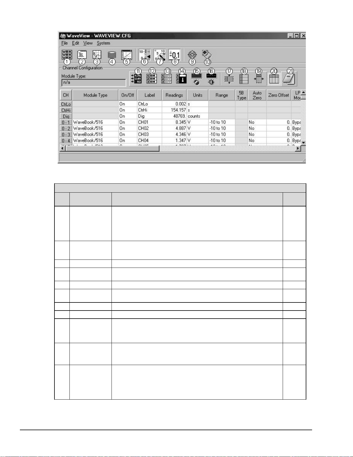
WaveView Configuration Main Window
WaveView Configuration Main Window, Button Identification
# Item Description
1 Module
Configuration
2 Acquisition
Configuration
3 Scope Window Opens the Scope W i ndow to display data acquisition waveforms in real -time. 27
4 Direct to Disk
Window
5 Vi ew File Dat a Starts an independent, post-data acquis i tion viewing program. 7
6 Bar Graph
Meters
7 Anal og Meters Used to display one or more channel s in analog meter format. 33
8 Digital Meters Used to display one or more channel s in digital meter form at. 34
9 WBK16 Sensor
Calibration
10 WBK16 Shunt
Mode
11 Enable [Disable]
Spreadsheet
Readings
Column
The Module Configuration column displays the current inventory of WaveBooks
and relevant WBK opt ions. Note that the W aveV i ew Configuration main window
provides a means of setting certain parameters for W BK options, e.g.., LPF
Type and LPF cutoff for WBK12 and WBK13, and excit at i on source amplitude
and offset for W B K 14. When applicable, the WBK options will be listed in the
Module Type column.
Opens the Acquisition Configuration display window to allow selection of the
number of scans, s can rate, and the triggering method to be us ed f or starting
the scan.
Provides a means of writing acqui red data to disk files. 7
Used to display one or more channel s in bar graph format. 32
Use of this button temporarily disables WaveV i ew and opens a s ensor
calibration spreadsheet so that each channel on a WBK16 can be calibrated to
the specifications of the sensor in use.
: This selection is available only if WaveView detec ts a WBK16 module.
Note
With shunt mode enabled WBK16 channels are set to their shunt position f or al l
acquisition operations i f they were most recently calibrated using the shunt
method.
This is an Enable/Disable toggle button. Use of this button to “enable” causes
all channels that are “On” to display an actual reading of the input signal in the
channel reading column. The readings column is updated about twice per
second. A status i ndicator “READINGS” appears above the spreadsheet when
the column is enabled. S i nce this is a toggle button, pressing it while the
readings column is enabled will disable it.
See
Page…
10
22
See
WBK16
Document
Module
See
WBK16
Document
Module
--
WaveView, pg. 2
03-05-02
WaveView
Page 5

WaveView Configuration Main Window, Button Identification
# Item Description
12 Make All
Channels
Active
13 Make All
Channels
Inactive
14 Fill Down When multiple cells within a column are selected, this command t ak es the top-
15 Auto Zero Active
Channels
16 Clear All Zero
Offsets
17 Hide Inactive
Channel Rows
18 Show All Rows Makes all channel rows visible. Can be used to restore the full spreadsheet
19 Customize
Column
Layout
20 Show All
Columns
21 Copy Visible
Cells to
Notepad
Makes all channels acti ve. When this button is pressed, the word “On” appears
in the On/Off column for every channel.
Makes all channels inact i ve. When this button is pressed, the word “Off”
appears in the On/Off column for every channel. If your channel scan includes
only a few channels, it may be easier to make all of the channels inactive, then
turn on the few desired channels.
most selected cell and copies its contents to the selected cells below.
This button zeros out a DC offs et signal on all channels that are “On” and have
Auto Zero set to “Yes.” Note that Auto Zero does not apply t o WBK17.
This button clears the zero of f set that was set with the Auto Zero Act i ve Channel
button. Note that Auto Zero does not apply to WBK17.
Hides all inactive channels, thus only the active (On) channels are di splayed.
A status indicat or “HI DDEN ROWS” appears above the spreadsheet when one
or more channels are hidden.
When a channel is hi dden, i ts configuration settings cannot be changed.
Note:
Block operations and other “All” acti ons, like the Make All Channels Active
menu item, have no eff ect on hidden channels.
after a Hide Inactive Channels action has been performed.
Opens a Customize Colum n Layout window that allows you to select the
columns that you want to have displayed. This feature allows you to hide
columns that do not appl y to your application. For example, WBK17 users may
want remove the Auto Zero, Source Level, Bridge Type, and Invert columns.
When this pus h-push button is depressed, all spreadsheet columns are shown
and the button remains indented. Pushing the button again shows the
spreadsheet with the customized column layout, as set up using button 19.
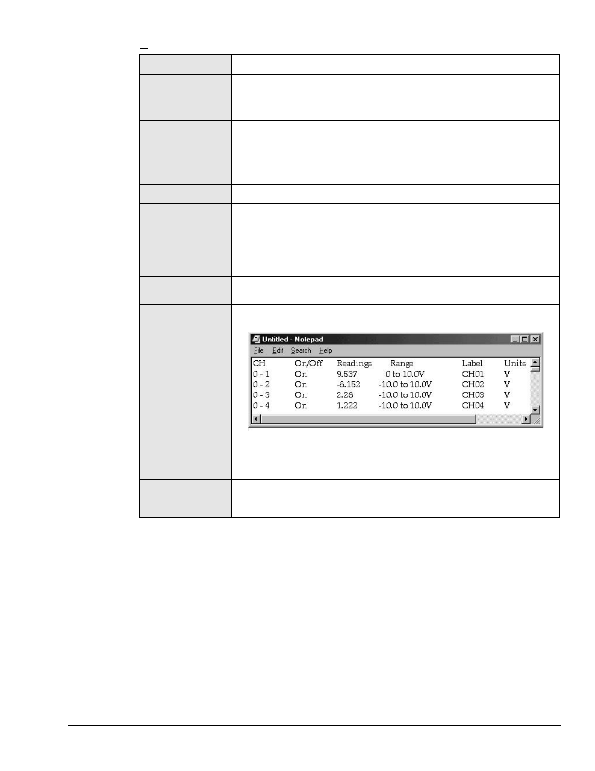
Places a tab-delimi ted text version of the spreadsheet into Micros oft’s Notepad
application. The inform ation can be imported into various spreads heet
programs, such as Mic rosoft Excel.
See
Page…
--
--
--
--
--
--
--
--
--
9
Software Startup & Sample Acquisition
The program installation CD-ROM contains both a 16-bit and a 32-bit version of WaveView. The figures in
this document module reflect the 32-bit version, only. Note that the 16-bit version has fewer toolbar
buttons and exhibits minor screen differences.
Startup WaveView
Start WaveView by double-clicking on its icon. WaveView holds user-configured parameters that can be
saved to disk. The default configuration filename is
the working directory for this configuration file. One of the following situations will occur:
•
If the default configuration file is f ound, all the required setup information is extracted from it, and
the application’s main window opens.
•
If the default configuration file is not found, WaveView attempts to connect with WaveBook using
the following default parameters: Printer Port LPT1, Interrupt Level 7, and 4-bit Standard Protocol. If
this fails, the program tries LPT2 and Interrupt Level 5.
•
If connection is established, WaveView’s main window opens.
Note: If connection to the device can not be
established, a WaveView StartUp box
appears with the following options:
Retry, Select Device, Load File, and Exit.
WAVEVIEW.CFG
. When WaveView starts up, it searches
WaveView StartUp Box
WaveView
03-05-02
WaveView, pg. 3
Page 6
Reference Note:
Refer to the WaveBook User Manual’s Troubleshooting chapter for advice regarding connection
problems.
•
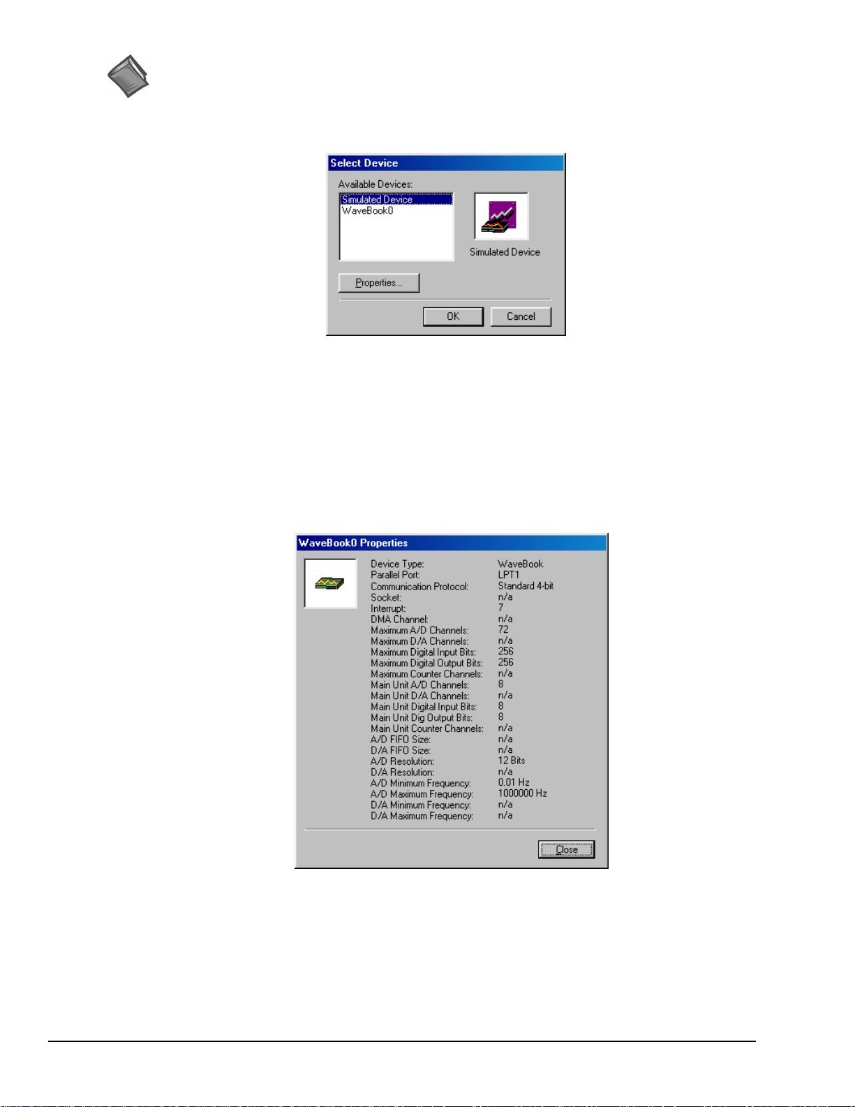
If no user-configuration file is found , or if no communication established, a dialog box prompts you
to choose an actual WaveBook from the device inventory, or to select a simulated device.
Select Device Box
Simulated WaveBook. If the hardware is not available, or if yo u j ust want to practice using the software,
select Simulated Device. The Simulated Device allows you to run vario us software functions with no
hardware concerns.
The Simulated mode is also available from WaveView’s pull-down menu. To select the simulated mode:
1. Choose Select Device from the System pull-down menu.
2. Select Simulated Device from the Available Devices list.
WaveBook Attached. If the WaveBook hardware is connected and switched on, select the applicable
WaveBook device. Then click on the Properties button to view the Device Properties screen (see following
figure).
Devices Properties (example)
After you have selected the device parameters, click Close.
WaveView attempts to find the WaveBook at the specified port. One of the following situations will occur:
•
The hardware is found, the WaveView main window opens.
•
The hardware is not found, a dialog box informs you and provides another chance to select
parameters.
WaveView, pg. 4
03-05-02
WaveView
Page 7
WaveView interrogates the hardware after it starts up to see what options and expansion modules are
actually connect ed to the WaveBook. The number of channels (shown on the co nfiguration menu)
represents the number of channels actually connected to WaveBook.
Configure Channels
Once WaveView determines the options and expansion modules, the individual channels can be configured,
as described in the text that follows.
If WaveView cannot identify the hardware, and you have verified that the selected hardware
parameters are correct, exit WaveView and then use the “Test Hardware” feature of the
Daq* Configuration control panel. A discussion of System Testing is included in the
System Setup and Power Options chapters of WaveBook Manuals 481-0901 and 489-0901.
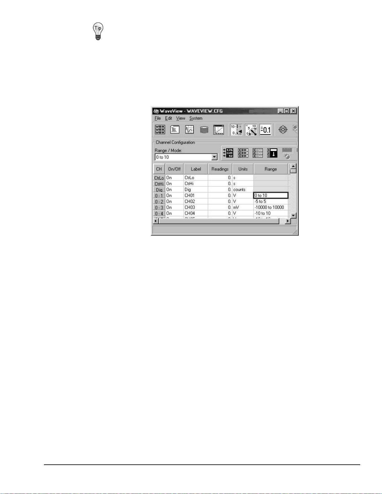
Configuring Channels from Wa veView’ s Main Window (Partial View)
•
On/Off - To acquire data with WaveView, channels must be properly connected to signal sources, and
must be enabled (On). Channels can be enabled as follows:
(1) Click in a channel’s On/Off cell, then select "On" from the drop-down menu (that appears
above the range column), or
(2) Double-click in a channel’s On/Off cell to toggle to “On.” Note that the on/off status will
change with each double-click, or
(3) Click on the toolbar’s “On” button (Make All Channels Active) to turn all channels on. Note
that the “Off” button (Make All Channels Inactive) turns all channels off.
•
Label - Channels have default labels, such as CH05. You can change the label by clicking on the cell,
then typing in the new label. Labels must be unique, i.e., each channel must have its own label.
Attempts to use duplicate labels, or use no label will result in a warning message.
•
Readings - Not user configurable. This column displays values of enabled channels.
•
Units - Select a channel’s units in one of two ways.
(1) Click in a channel’s Units cell, then select the desired units from the p ull-down menu.
(2) Double-click in a channel’s Units cell to cycle through the units. Note that when the mX+b
dialog box appears you need to click “OK” to continue cycling.
Note: You can enter user-defined units from the mX+b dialog box, and you can use the mX+b
equation to adjust a channel’s scale and offset. Refer to Units on page 14 for more information
and an example of the mX + b equation being used.
•
Range - Select a channel’s range in one of two ways.
(1) Click in a channel’s Range cell, then select the desired range from the drop-down menu.
(2) Continue to double-click in the applicable channel’s Range cell to cycle through the available
ranges. Stop double-clicking when the desired range is indicated.
WaveView
03-05-02
WaveView, pg. 5
Page 8
Configure Acquisition
The following text describes how to configure an acquisition.
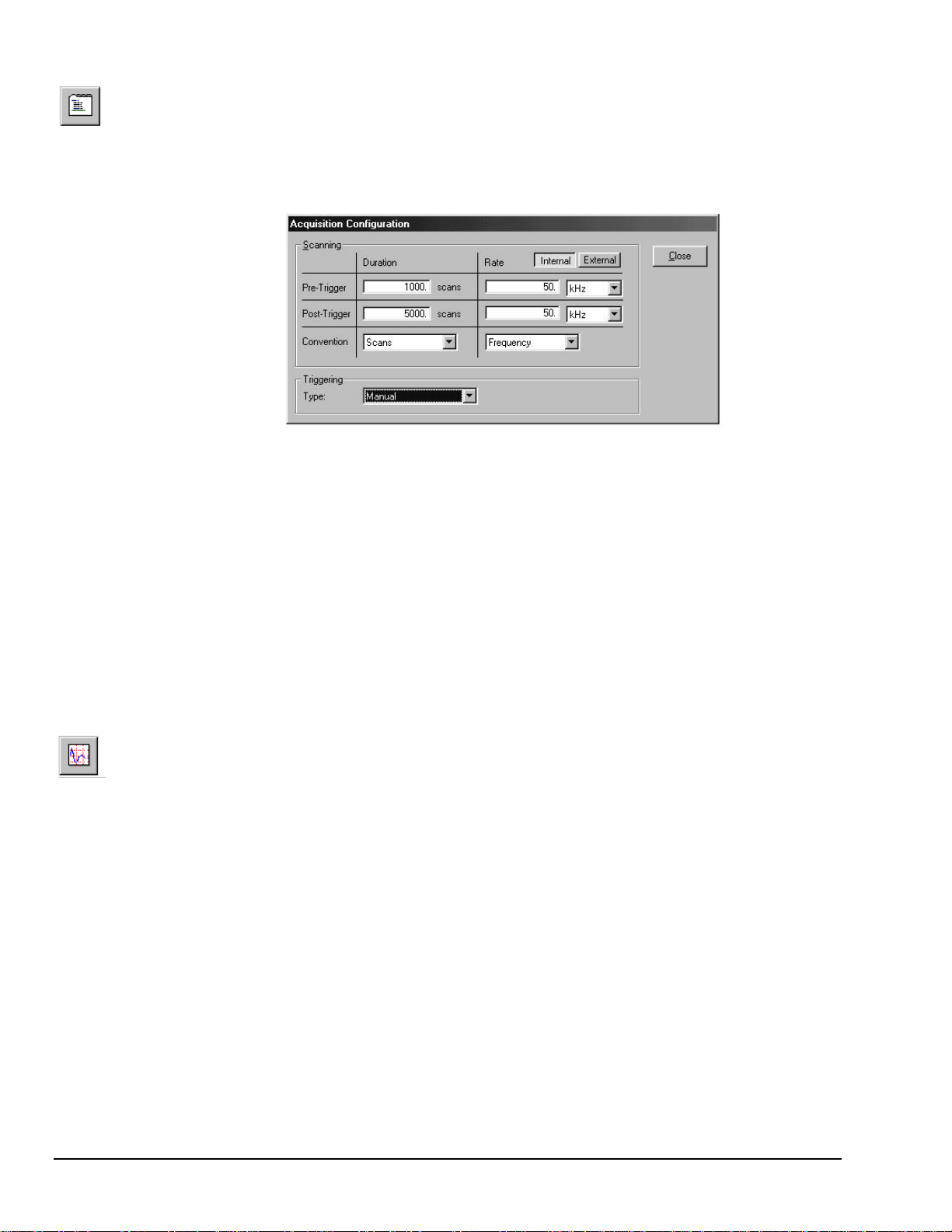
After completing channel configuratio n, select the Acquisition Configuration option from the View menu or
the tool bar. The following figure represents the Acquisition Configuration dialog box. The parameters
shown are a result of the values entered below.
Acquisition Configuration Dialo g Box
Triggering
Type: Manual
Scanning Duration
Convention: Scans
Pre-Trigger: 1000 scans
Post-Trigger: 5000 scans
Scanning Rate
Clock: Internal
Convention: Frequency
Pre-Tri gger: 50 kHz
Post-Tri gger: 50 kHz
After entering the values, click the Close button to set the acquisition parameters.
Collect and View Data
The following text describes how to collect data for a sample acquisition, and how to view a graphic
representation of the data.
To read and view a graphic representation of WaveBook data, select the Scope option from the View menu
or use the toolbar button. This accesses the WaveView Scope window. Complete the acquisition setup as
follows:
•
Number of Charts. First, the Scope window should be configured to display 4 charts since 4 channels
were previously selected for the acquisition. Select the Number of Charts option from the Charts menu
item. When the flyout appears showing a selection of up to 8 channels for display, click on 4.
•
Arm and Trigger. The system is now set to start collecting data. At this point, you ma y acquire one
acquisition or continuous acquisitions. For this sample acquisition, click the Arm button, then click the
Trigger button.
•
Data Acquisition. The system has now collected 1000 pre-trigger scans and 5000 post-trigger scans.
WaveView, pg. 6
03-05-02
WaveView
Page 9
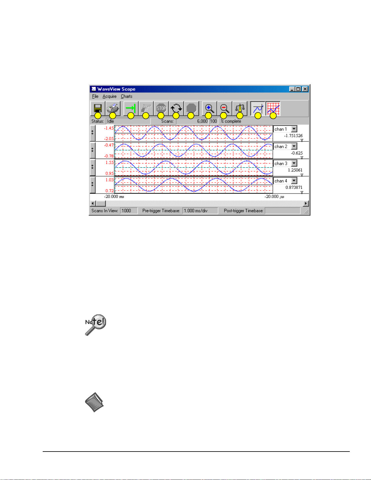
If desired, you may modify the current Scope window display as follows:
6789101
5432
•
View additional channels (up to 8) simultaneously by changing the entry in the Number of Charts
menu.
•
Change the channels viewed. Use the channel select list box at the right of the waveforms to display
waveforms of other active channels.
•
To scale the waveforms, click on the Scale All Charts button. All 4 waveforms should then be visible.
•
Examine the waveforms at any point along the timeline by using the horizontal scroll-bar.
•
Vary the number of scans displayed by using the Zoom In or Zoom Out buttons.
..
1
WaveView Scope Window
Item Description Item Description
1 Save 7 Stop Rearming
2 Print Window 8 Zoom In
3 Arm 9 Zoom Out
4 Trigger 10 Scale All Charts
5 Stop Acquiring 11 Toggle Cross Hairs
6 Auto-Rearm 12 Toggle Grids
1 12
Store Data
[and View File Data],
Option
Data to be viewed with the post acquisition data viewer must be in the appropriate
binary format. From WaveView, you can select the format by navigating as follows:
⇒
WaveView Main Window
File ⇒ Data Conversion Preferences and check the
appropriate box.
Save collected data to disk by clicking on the Save button (" floppy disk" or left-most button) of the
WaveView Scope window, and then giving the file a name. Note that you can analyze the saved data with a
post-acquisition data-viewer program, such as PostView, DIAdem, or eZ-View.
To open an installed post-acquisition data viewer application, return to the WaveView Configuration main
window then click on the View File Data toolbar button (button 9 in the following figure).
Reference Note:
For detailed information regarding post acquisition data analysis programs, refer to the
WaveView
applicable document module(s), e.g., DIAdem, PostView, or eZ-View.
03-05-02
WaveView, pg. 7
Page 10

WaveView, A Detailed Reference
When WaveView starts it interrogates the system hardware to see what options and expansion modules are
actually connected to the WaveBook. Unless you are using WaveView’s simulated mode, the channels
displayed on the WaveView.cfg window correspond to actual connected channels.
WaveView functions are initiated through toolbar buttons and pull-down menu selections. The toolbar
buttons were identified on page 2. An explanation of menu functions, in order of the menu structure, begins
in the "Pull-down Menu Commands" section, below.
Toolbar Buttons
Reference Note:
Pull-Down Menu Commands
The following menu descriptions apply to corresponding toolbar buttons (as depicted in the WaveView
Configuration Main Window, and in the related table (as seen on page 2). Note that some menu items have
no corresponding toolbar button.
File
New
Open
Save
Save As
Convert Data Files
Data Conversion
Preferences
Open WBK16
Calibration File
(WBK16 Only)
About
Exit
Toolbar buttons are identified and explained in the figure of the
Configuration Main Window
Sets all parameters t o their default startup settings.
Loads a saved configuration.
Saves the existing configurati on for later recall.
Prompts for a file name and saves the current configurat i on to that file name.
Runs the File Converter, which converts any acquired data file to any of the supported data
types.
Opens a dialog box, which lets you set the dat a f i l e conversion options that WaveView will
apply automatically whenever you acquire dat a.
Loads a WBK16 s ensor calibration table. This command loads saved WB K 16 calibration
data.
This selection is not avai l able unless WaveView detects the presence of a WBK 16.
Note:
Provides software version number and provi des access to a list of devi ce properties.
Closes WaveV i ew.
Before WaveView exits, i t saves the current configuration i n a file named
Note:
WAVEVIEW.CFG. The next time you run WaveView, this file is loaded automatically.
WaveView
, and in the related table. Both can be seen on page 2.
WaveView, pg. 8
03-05-02
WaveView
Page 11
Edit
Make All Channels
Active
Make All Channels
Inactive
Fill Down
Hide Rows of Inactive
Channels
Show All Rows
Customize Column
Layout
Reset Column Layout
Show All Columns
Copy Visible Cells to
Notepad
This command plac es an “On” in the “On/Off” field of all channels.
This command plac es an “Off” in the “On/Off” field of all channels. If your channel scan
includes only a few channels, it may be easier to make all of the channels inactive, then
turn on only those few channels that you want.
When multi pl e cells within a column are selected, this command takes the top-most
selected cell and copies its contents to the selected cells below.
Temporarily removes all inactive channels from the channel configuration spreadsheet. If
there are inactive (“Off”) channels, this results in a small er spreadsheet showing just the
currently active channels. A status indicator “HIDDEN ROWS” appears above the
spreadsheet when one or more channels are hidden.
When a channel is hi dden, i ts configuration settings cannot be changed. Block
Note:
operations and other “All” actions, li ke the Make All Channels Active menu item, have
no effect on hidden channels.
Makes all channel rows visible. Can be used to restore the full spreadsheet af ter a Hide
Inactive Channels action.
Opens a Customize Colum n Layout window that allows you to select the columns that you
want to have displayed. This feature all ows you t o hide columns that do not apply to your
application. For example, WBK17 users may want remove the Auto Zero, Source Level,
Bridge Type, and Invert colum ns.
This resets the custom column layout sett i ngs to the default values. All adjustments to
column widths will be lost and hidden columns will return to the spreadsheet. Once the
column layout is res et, there is no automatic recovery of the customized layout. Compare
this command with “Show All Columns.”
Displays all columns, including the
This button and the Custom i ze Col umn Layout button can be used to switch bac k-andforth between the full view of the spreadsheet (al l columns) and the custom i zed l ayout.
Places a tab-delimi ted text version of the spreadsheet into Micros oft’s Notepad application.
The information can be imported into various spreadsheet programs, such as Microsoft
Excel.
Module Type
column, which is typically not displayed.
Enable Spreadsheet
Reading Column
Auto Zero Active
Channels
Clear All Offsets
An Example of Visible Cells Copied to Notepad
This causes all channels that are “On” to display an actual reading of the input signal in the
channel reading column. This column is updated with new readings about twice per
second. A status i ndicator “READINGS” appears above the spreadsheet when the
reading column is enabled.
This zeros out a DC offset signal on all channels that are “On” and have Auto Zero set to
“Yes.” Note that Auto Zero does not apply to WBK17.
This clears the zero offs et that was set via the Auto Zero Active Channel.
Note that Auto Zero does not apply t o WBK17.
WaveView
03-05-02
WaveView, pg. 9
Page 12
View
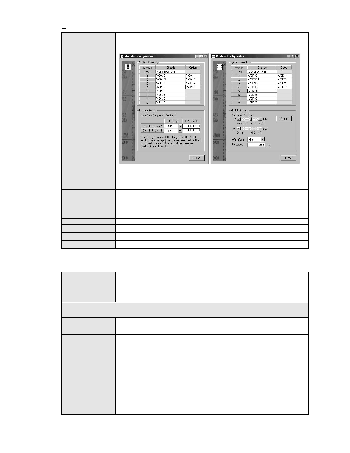
Module Configuration
Displays the current invent ory of expansion modules that are in the WaveBook system. I n
addition, the window provides a means of s et ting certain expansion module parameters,
i.e., LPF Type and LPF cutoff for WBK12 and W B K 13 options and excitation source
amplitude and offset for WBK14. The following figure provides two examples.
Two Examples of the Module Configuration Display Window
The window can be accessed from the View pull-down menu or by using the
associated toolbar button (1).
Acquisition
Configuration
Scope Window
Direct to Disk
Window
View File Data
Bar Graph Meters
Analog Meters
Digital Meters
Opens the display window to allow selection of t he number/speed of the scan and the
triggering method to start the scan.
Opens the display window to allow real-time viewing of t he acquired data.
Opens the display window to allow the writing of acquisit i on data to disk files.
Starts the independent application to view file data.
Used to display one or more channel s in bar graph format.
Used to display one or more channel s in analog meter format.
Used to display one or more channel s in digital meter form at.
System
Select Device
Options
: The following System sel ections apply only to WB K16 and are only available if a WBK16 module is detected.
Note
Refer to the WBK16 document module [in the 489-0902 WBK options manual] for additional information.
WBK16 Sensor
Calibration
WBK16 Shunt Mode
WBK16 LPF Corner
Frequencies
Brings up a dialog box that lets you sel ect a WaveBook device. I t also provides access to
the Simulated Device, which is listed as an option.
Brings up the WaveV i ew System Options dialog box. From there, you c an enabl e or di sable
WaveView options. The opt i ons dialog box has three tabs:
Module,
This command runs the s ensor calibration program. Selecting this option will tem porarily
disable WaveView and open a sensor calibration spreadsheet so that each channel on a
WBK16 can be c al i brat ed to the specifications of the sensor in use.
This command plac es WaveView in a shunt mode. When in this mode, all enabl ed WBK16
channels are set to their s hunt position for all acquisiti on operations, providing that the
channels were last calibrated us i ng t he shunt method.
During shunt mode operation, s preadsheet updating, scope window operations, analog
meter operations, and direc t-to-disk operations result in dat a that represents the raw
value of the shunt resist or.
Note that the shunt mode can be used to verify that the acquired shunt val ue agrees with
the expected shunt value.
This command brings up a di al og box to sel ect new cutoff frequencies for the LPF on a
WBK16. The WBK16 has a Low Pass Filter with two selectable cutoff frequencies.
Although the frequencies are f actory configured at 10 Hz and 1 kHz, changing the res i stor
packs inside the WBK16 can modify them. After the cutoff frequencies are altered, the
values that WaveView displays can then be modified to match the LPF frequencies using
this command.
and
WBK17.
The three tab selections are discussed, following this table.
Performance, Memory
WaveView, pg. 10
03-05-02
WaveView
Page 13
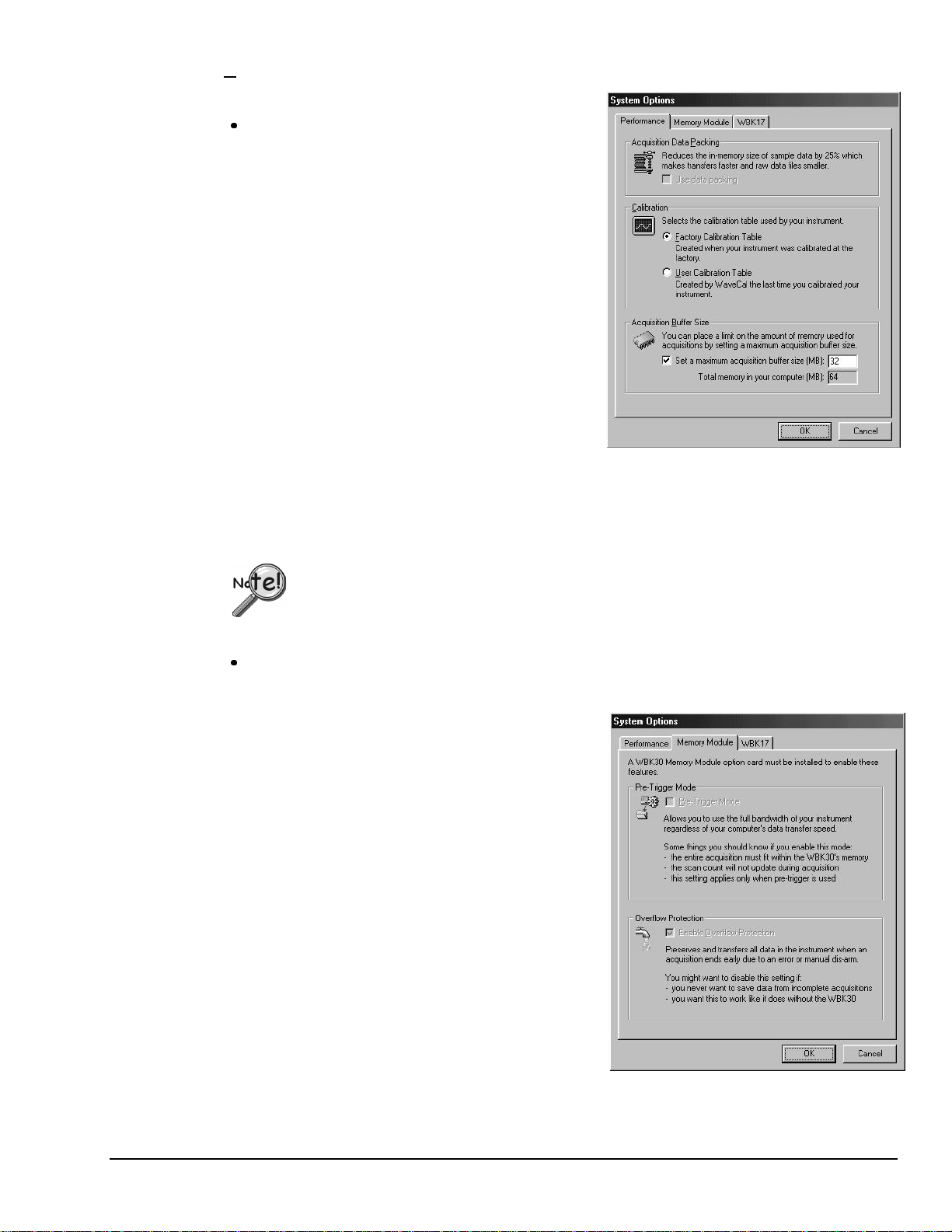
System …
Options
“Performance” Tab
zz
Acquisition Data Packing
(WaveBook/512 and /512H Only)
WaveBook/512
transfer it to WaveView in 16-bit words. Data can be
compressed so four 12-bi t samples are packed into three
16-bit words. This reduces transf er time and data storage
requirements. Use packed data if buffer overrun errors
occur. Disadvantages include extra processing time for
unpacking data and some loss in resolution (less than ½
LSB).
The Data Packing option does not appl y t o t he
WaveBook/516, /512A, /516A, or to WavePorts,
and is disabled for these devices.
•
Calibration
Factory Calibration Table
factory generated calibration constants of each system
component to achieve cal i bration of the system. This i s
useful if the system calibration changes often.
User Calibration Table
perform a calibration of the complete signal path from input
to A/D stage. The cal c onstants are stored in the Calibration
Table on the WaveBook main board. Recalibration is
required when any part of the signal path changes. Thi s
method is useful when the conf i guration remains stable and
you want slightly better accurac y.
and
:
devices acquire 12-bit data and
/512H
(
default),
, the WaveCal program lets you
the software uses the
:
System Options
Performance Ta b Selected
WavePort
In regard to WavePort devi ces, leave the Calibration Radio Button selected to Factory Calibration Table.
WBK17
For WBK17, leave t he Cal i bration Radio Button selected to Factory Calibration Table.
zz
Acquisition Buffer Size
Allows you to set a new buffer size for dat a acquisition. The dialog displays the maximum size of the acquisition
buffer. The buffer is never sized l arger than needed by the acquisition. For a one-channel, 1000 scan acquisition
the buffer will be 2000 bytes,
devices should only be calibrated at the factory, or by a factory-authorized service representative.
modules should only be calibrated at the factory, or by a fact ory-aut hori zed service representative.
:
the size shown in the dialog.
not
“Memory Module” Tab
: The WaveView System Memory Module Option settings
Note
are only pertinent if a WBK30 Memory module option
card is installed in your WaveBook.
•
Pre-Trigger Mode
bandwidth of your instrument regardles s of the computer's
data transfer speed. Note that when Pre-Trigger i s in
effect, certain conditions apply: (1) The entire acquisit i on
must fit in the WBK30's internal memory, (2) The scan
count will not update during acquisition, and (3) The PreTrigger Mode selection only applies if pre-trigger is used.
•
Overflow Protection
data in the instrument when an acquisition ends early due to
an error or manual disarm.
This option should not be used if you: (1) Never want to
save data from an incomplete acquisition, or (2) You want
the option to work like it does without a WBK30 installed.
: This allows you to use the full
: This preserves and transfers all
WaveView
03-05-02
System Options
Memory Module Tab Selected
WaveView, pg. 11
Page 14
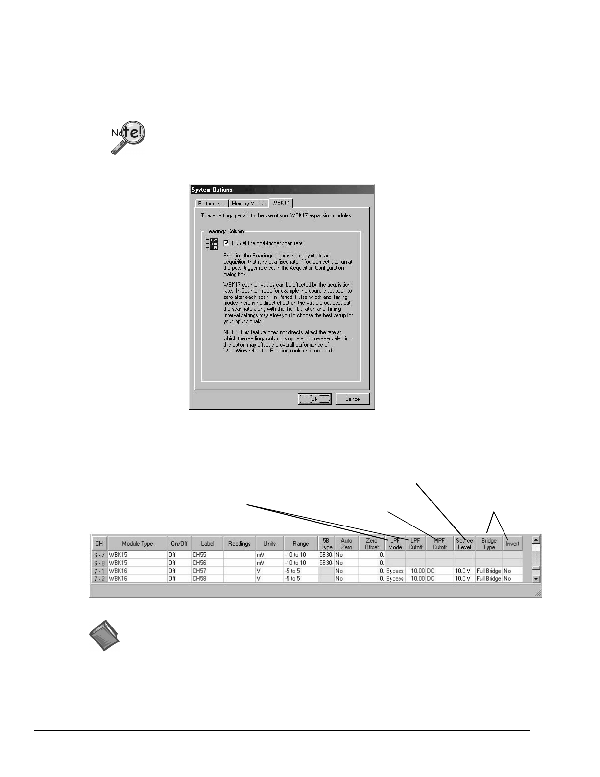
“WBK17” Tab
H
A
W
S
A
The “WBK17” tab provides a means of setting the Readings column to run at the post-trigger scan rate.
This system option applies only to WBK17 modules and impacts the Readings Column of WaveView’s
main window.
Setting the Readings column to run at the post-trigger scan rate does not directly affect the
rate at which the Readings column is updated; However, implementing this feature may
affect the overall performance of WaveView while the Readings column is enabled.
Input Channel Configuration
LPF Mode and LPF Cutoff
Apply to: WBK12, WBK13,
WBK14, WBK16, and WB K 17
Reference Note:
The above figure does not include WBK17-exclusive columns. See page 17 in regard to additional
columns that are dedicated specifically to the WBK17 module.
WaveView’s configuration spreadsheet provides is used to configure channels and display channel readings.
The top few rows are used for the high-speed digital input and other non-analog channels. The remaining
rows (up to 72) are used for analog input channels. The number of rows varies depending on system
configuration.
System Options, WBK17 Tab Selected
ource Level
pplies to: W BK14 and WBK16
PF Cutoff
pplies to: W BK14,
BK16, and WBK 17
Columns of the Channel Configuration Spreadsheet
Bridge Type and Invert
Apply to: WBK16 only
WaveView, pg. 12
03-05-02
WaveView
Page 15

The various columns contain the configuration information for each channel. Some columns allow blocks of
cells to be altered simultaneously, while others allow one cell to be changed at a time. Some columns may
be static and cannot be altered. Clicking a column header will select the entire column if applicable.
A discussion of each column follows.
- The channel number column labeled CH is static and cannot be altered. This column identifies the
CH
analog (or digital) input channel to be configured in that row. This number includes all channel numbers
from the WaveBook and any attached expansion chassis (WBK10/10H, WBK14, WBK15, WBK16, and
WBK17). The channels are numbered as follows:
CH Description Default Label
CtrLo External Clock Period (Lo); Appli es to WaveBook/516, / 512A, /516A CtrLo
CtrHi External Clock Period (Hi); Appl i es to WaveBook/516, /512A, /516A CtrHi
Dig WaveBook Digital Channel Dig
0-1 to 0-8 WaveBook Analog Channels CH01 to CH08
1-1 to 1-8 First Expansion Channels CH09 to CH16
2-1 to 2-8 Second Expansion Channels CH17 to CH24
etc. etc. etc.
Module Type –
“Customize Column Layout Window” that is activated by toolbar button (17), or by clicking the “Show All
Columns” button (18). The column identifies the types of modules and their installed option cards, if
applicable. The column’s information is automatically derived from the WaveBook system’s actual
hardware.
On/Off
will toggle the channel status, i.e., On to Off and visa versa. The Make All Channels Active and
Make All Channels Inactive menu items under the Edit menu can be used to simultaneously enable or
disable all channels.
➪
WBK17 Note -
each combination of the analog, counter low word, and counter high word values that can be acquired for
each WBK17 channel. The selected 16-bit values will be written to acquisition files and be available for
display in the Scope window.
Column.
“Volts and CtrLo (VL)”, “Volts and CtrHi (VH)”, “CtrLo and CtrHi (LH)”, and “Volts and CtrLo and
CltrHi (VLH)”. Long strings will fit in the selection list, but the On/Off column itself would use an
abbreviation, as follows: “Off”, “On;V”, “On:L” , “On:H” , “On:VL” , “On:VH” , “On:LH” , “On:VLH.”
Label -
that is similar to its channel number, but this can be changed to any combination of 8 characters. Click on
the desired cell, and type in the desired label name.
➪
WBK17 Note -
between the values: Volts, Co unter Low, and Counter High, a “-V”, “-L” or “-H” is appended to the label.
This column allows you to enable and disable channels. Do uble-clicking a cell in this column
-
The complete contents of the “On/Off” list are: “Off”, “Volts (V)”, “CtrLo (L)”, “CtrHi (H)”,
This column contains a descriptive name for the input channel. By default, it contains a label
This column is hidden by default, but can be displayed by selecting it in the
The On/Off column will contain a list of 8 different On/Off combinations, i.e., one for
Only one of the selected values will be shown in WaveView’s Readings
There will only be one user-defined la bel for all three 16-bit values. To distinguish
WaveView
Readings -
➪
WBK17 Note -
If the On/Off column selection indicates multiple 16-bit values, WaveView will make an automatic
selection of which value to display in the Readings column. This automatic selection will be according to
the following rule: the CtrLo value is preferred over the Volts value, and the CtrHi value is preferred over
the CtrLo value.
Unlike the Readings Column, acquisition data will include all selected WBK17 16-bit data channels.
For example, if “Volts and CtrLo and CtrHi” were selected as the “On/Off” value for all 8 channels of a
WBK17, the acquisition data file would contain data from twenty-four 16-bit channels.
Not user configurable. This column displays values for all enabled channels.
The Readings column will show, at most, one 16-bit value associated with the channel.
03-05-02
WaveView, pg. 13
Page 16

Units -
when the Scope option is selected. When a cell is selected, a selection box gives you a choice between volts
(V) or millivolts (mV). You can also enter user units and mX+b scales from this point. Making a selection
sets the choice into the individual cell or block of cells. This option has no effect on the Digital Input
channel. A discussion of mX +b follows.
From the Customize Engineering Un its dialog box, you can enter values for m and b components of the
equation that will be applied to the data. There is also an entry field that allows you to enter a label for the
new units that may result from the
This column allows you to change the voltage scale setting of each analog channel displayed
Customize Engineering Units Dialog Box
calculation.
mX+b
An example of mX + b equation use follows.
Engineering Units Conversion Using mx + b
Most of our data acquisition products allow the user to convert a raw signal input (for example, one that is
in volts) to a value that is in engineering units (for example, pressure in psi). The products accomplish this
by allowing the user to enter scale and offset numbers for each input channel, using the software associated
with the product. Then the software uses these numbers to convert the raw signals into engineering units
using the following “
mx + b
” equation:
Engineering Units = m(Raw Signal) + b (1)
The user must, however, determine the proper values of scale (m) and offset (b) for the application in
question. To do the calculation, the user needs to identify two known values: (1 ) the raw signal values, and
(2) the engineering units that correspond to the raw signal values. After this, the scale and offset parameters
can be calculated by solving two equatio ns for the two unknowns. This method is made clear by the
following example.
Example
An engineer has a pressure transducer that produces a vo ltage output of 10.5 volts when the measured
pressure is 3200 psi. The same transducer produces an output of 0.5 volt when the pressure is 0 psi.
Knowing these facts, m and b are calculated as follows.
A - Write a pair of equations, representing the two
known
points:
B - Solve for m by first subtracting each element in equation (3) from equation (2):
WaveView, pg. 14
3200 = m(10.5) + b (2)
0 = m(0.5) + b (3)
3200 - 0 = m(10.5 – 0.5) + (b - b) (4)
03-05-02
WaveView
Page 17

Simplifying gives you:
3200 = m(10) (5)
This means:
C - Substitute the value for m into equation (3) to determine the value for b:
So
:
Now it is possible to rewrite the general equation (1) using the specific values for m and b that we just
determined:
b = - 160 (8)
m = 320 (6)
0 = 320 (0.5) + b (7)
Engineering Units = 320(Raw Signal) - 160 (9)
The user can then enter the values of m and b into the appropriate location using the facilities provided by
compatible data acquisition software, for example: WaveView, Daq View, Personal DaqView, LogView,
and TempView. The software uses equation (9) to calculate signal values in engineering units from that
point on.
Range –
mouse in any of the analog channel
This column allows you to set the gain and polarity for the selected channel(s). Clicking the
Range
boxes brings up the "Select Range" selection box.
The range of gains available in the select ion box depends on the hardware installed in the
system. Double-clicking on a channel’s
Range
The
selections have no effect on the Digital Input channel.
Range
box will cycle through the available ranges.
5B Type –
Auto Zero
present in a channel. WaveView nulls out the offsets o f all channels set to “Yes” in the Auto Zero column,
providing the channels are enabled (“On”).
➪
WBK17 Note -
LPF Mode -
you to include or bypass a channel’s low-pass filter. The bypass mode is the default. Double-clicking a cell
in the LPF Mode column will cycle through the available options, i.e., “On” and “Bypass.”
➪
WBK12 and WBK13 Note
window, accessible via the associated toolbar button “1,” or from the View pull-down menu. The LPF type
and Cutoff settings apply to channel banks, not to individual channels. WBK12 and WBK13 each have two
banks of four channels. Setting one channel of a bank updates the banks remaining channels.
➪
WBK14 Note –
or “External.” The later is used to select an external filter.
LPF Cutoff –
you to set the low-pass filter cut-off frequency for the selected channel(s). Since the WBK12 and WBK13
filters are assigned to banks, setting one channel of a bank updates the banks remaining channels. Note that
LPF Cutoff can only be set in the
button (1) and the
If a 5B module is being used, the type will be displayed when this column is visible.
(32-Bit WaveView Only).
The Auto Zero function does not apply to WBK17.
Applies to: WBK12, WBK13, WBK14, WBK16, and WBK17
– The LPF type (linear or elliptic) is set in the Module Configuration
For WBK14 applications, the LPF Mode column allows you to select “On”, “Bypass”,
Applies to: WBK12, WBK13, WBK14, WBK16, and WBK17
Module Configuration window
View
pull-down menu.
Auto-zero is used to null out any DC offset that might be
. This column allows
. This column allows
accessible via the associated toolbar
WaveView
03-05-02
WaveView, pg. 15
Page 18

HPF Cutoff –
pass filter cut-off frequency for the selected channe l( s) , or in the case of the WBK17, to select AC or DC
coupling. When a spreadsheet cell is selected [in the HPF cutoff column], a selection box above the
spreadsheet will display the options available for configuring the filters. Double-clicking a cell in this
column will toggle the cut-off frequency status. A change in the high-pass filter cut-off frequency for one
channel will appropriately update other affected channels.
Applies to: WBK14, WBK16, and WBK17
HPF Cutoff Options
WBK14 WBK16 WBK17
0.1 Hz DC Off
10 Hz 1 Hz AC
-- -- DC
. This column allows you to set the high-
WBK17 users
coupling can be turned off, or be selected for AC or DC coupling. The inclusion [or exclusion] of DC
offsets is important when calculating the appropriate comparator threshold for the input waveform.
In regard to WBK17’s
to prevent DC offsets from reaching the comparator. AC coupling works well when the input is constantly
changing. If the input stops for longer than one second, it will appear as DC and may cause the comparator
to switch on the decaying DC input.
In regard to WBK17’s
to be presented as input to the comparator DC coupling does not reject anything. If the input can have
periods of stability longer than one second, use DC coupling so the comparator does not switch on a
decaying DC input.
Source Level –
source level for the selected channel(s). When selecting a cell or block of cells in this column, a selection
box above the spreadsheet may or may not appear, depending upon your particular hardware. If the
selection box appears, it will display the appropriate source level selections (such as “Off”, “2 mA”, or
“4 mA” for a WBK14 or an excitation voltage level for a WBK16) allowed by your hardware to configure a
source or block of sources. Double-clicking a cell in this column will toggle the source level status. A
change in the source level for one channel will app r opriately update any other affected channels.
➪
WBK14 Note –
Set the current-source level to “Off” before measuring voltage.
Bridge Type –
configuration for a strain gage or load cell sensor. When a cell is selected, a selection box above the
spreadsheet will display the appropriate bridge configuration selections (such as Full Bridge, Half-Bridge
and Quarter-Bridge). Double-clicking a cell in this column toggles the Bridge Type. Detailed information
is included in the WBK16 Document Module.
should note that each WBK17 channel has a programmable input-co upling feature. Input
AC coupling option
DC coupling option
Applies to: WBK14 and WBK1 6
For WBK14, when using an ICP transducer, either 2 mA or 4 mA must be selected.
Applies to WBK16 Only
– select “AC” to reject unwanted DC offsets. In other words,
– use “DC” coupling when both AC and DC components are
. This column allows you to apply or remove the
. This column allows you to select the specific bridge
Invert –
When a cell is selected, the selection box above the sp readsheet allows “Yes” or “No” options to determine
whether the channel is inverted. Double-clicking a cell in this column will toggle the invert status.
WaveView, pg. 16
Applies to: WBK16 Only
. This column allows you to invert the signal level of a channel.
03-05-02
WaveView
Page 19

The remaining columns apply only to the WBK17 module.
T
D
i
Reference Note:
Refer to the WBK17 Document Module (in the WBK Option Cards and Modules User’s Manual,
p/n 489-0902) for detailed information regarding the various modes. The WBK17 document
module includes explanations, block diagrams, and examples.
hese 7 columns apply only t o WBK17 modules.
etailed information regarding operational aspects
s provided in the WB K17 document module.
WaveView Configuration Window Showing WBK17-Dedicated Columns
Counter Mode
–
Applies to WBK17 Only
.
WaveView supports several counter modes and can receive input
from up to two encoders (in 1X, 2X, or 4X modes).
All WBK17 modes are detailed in the WBK17 Document Module.
:
Note
The Encoder Mode can only be selected on WBK17
channels x-1 and x-5. Inputs “B” and “Z” must b e
connected to the next consecutive channels.
Reference Note:
Refer to the WBK17 Document Module (in the WBK
Option Cards and Modules User’s Manual,
p/n 489-0902) for additional information regarding the
Counter Mode Pull-Down List
•
Counter
following counter modes.
The counter ma kes use of a 16-bit counter (Counter Lo w), or a 32-bit counter (Counter High). While
in this mode, the channel’s input increments the counter. The counter is cleared at the beginning of
each scan, and the value [just prior to clearing] is latched and returned to the WaveBook/516, /512A,
or WaveBook/516A. See the upcoming Programmer Note.
•
Totalize
The totalize mode makes use of a 16-bit co unter (Counter Low), or a 32-bit counter (Counter High) .
While in this mode, the channel’s input increments the counter and rolls it over, resulting in a
cumulative total for the counter value. (see the following Programmer No te)
Programmer Note:
In regard to programming, the “Counter Mode” involves selecting the “Clear on Read” option
within a single “Counter/Totalize Mode;” and the “Totalize Mode” involves selecting the
“Totalize” option. In WaveView, the Counter and Totalize modes are treated as two distinct
modes.
Note that the “
Clear on Read
” mode is not available when using an external clock.
Refer to the WBK17 Document Module (in the WBK Option Cards and Modules User’s Manual,
p/n 489-0902) for additional information.
WaveView
03-05-02
WaveView, pg. 17
Page 20

•
Frequency
This mode pr ovides a means of displaying the frequency of the channel i nput, even though the WBK17
does not actually supply frequency data. This is possible since frequency is reciprocal function of the
period, i.e., “1 divided by period.” W hen the frequency mode is selected, WaveView automatically
performs the conversion (1/period).
The frequency data is latched as it becomes available and the data is sent to the Wavebook/516, /512A,
or /516A at the scan rate. Therefore, if the scan period is much faster than the input waveform, there
will be a great deal of repetition in the frequency values.
The “Timing Intervals” feature, page 21, determines the number of periods to time [per measurement].
This relates to frequency since the frequency reading is the reciprocal of the period value. Possible
timing interval values are: 1, 10, 100, and 1000. The “Timing Interval s ” feature only applies to the
Period and Frequency modes.
: Frequency is 1/Period. The Timing Interval and Tick Duration set the Period Range.
Note
Reference Note:
Refer to the Period Mode section of the WBK17 Document Module for additional information
that pertains to frequency (1/period).
Counter Mode
•
Period
This mode allows for period measurement of the channel input. The measurement period is the
time from edge-to-edge, either both rising or both falling. Period data is latched as it becomes
available and the data is sent to the Wavebook/512A, /516A, or /516 at the scan rate. Therefore,
if the scan period is much faster than the input waveform, there will b e a great d eal of repetition
in the period values. This repetition is due to the fact that updates take place only when another
full period becomes available.
The “Timing Intervals” feature, page 21, determines the number of periods to time [per
measurement]. Possible values are: 1, 10, 100, and 1000. The “Timing Intervals” feature only
applies to the Period and Frequency modes. The frequency mode makes use of the reciprocal of
the period value.
: The Timing Interval and Tick Duration set the Period Range. Details are included in the
Note
WBK17 Document Module.
Reference Note:
Refer to the Period Mode section of the WBK17 Document Module for additional information.
•
Pulsewidth
This mode provides a means of measuring a channel’s pulsewidth. The measurement is the time
from the rising edge to the falling edge, or visa versa. The measurement will be either pulsewidth
low, or pulsewidth high, depending upon the edge polarity set in the debounce module.
Every time the pulsewidth measurement is latched from the counter, the counter is immediately
cleared and enabled to count the time for the next pulsewidth. The pulsewidth measurements are
latched as they become available.
(continued)
–
Applies to WBK17 Only
.
WaveView, pg. 18
: If the scan period is much slower than the input period, then the acquisitions will miss
Note
some pulsewidths. Decreasing the scan period will increase the number of different
pulsewidths received.
: The Tick Duration sets the Pulsewidth Range. Details are included in the WBK17
Note
Document Module.
Reference Note:
Refer to the Pulsewidth Mode section of the WBK17 Document Module for additional information.
03-05-02
WaveView
Page 21

•
Timing Mode
This mode provides a means of measuring time between two subsequent events, i.e., the edge of
one channel with resp ect to the edge of another channel. The edge selection is done in each
channel’s debounce setup. Whenever the time measurement is latched from the counter, the
counter is immediately cleared and enabled for accepting the subsequent time period, which starts
with the next edge on the main channel.
The data returned is interpreted as time measured in ticks. This data represents the number of
ticksize intervals counted during the timing measurement. There are four timebase settings:
20 ns, 200 ns, 2 µs, and 20 µs. These are often referred to as tick-sizes. The WBK17 uses
a 50 MHz, 10 ppm oscillator as a timing source.
If the input signal has a poor slew rate the timing mode will provide variant results,
dependant upon the comparator threshold.
In timing mode, time can be measured with a
counter. Since the time measurements always have a “stop at the top ” option enabled, the 16-bit
and 32-bit options dictate whether the measurement has a range of 0 to 65535 ticks or 0 to
4,294,967,295 ticks.
Reference Note:
Refer to the Timing Mode section of the WBK17 Document Module for additional information.
•
Encoder
The encoder mode allows the WBK17 to make use of data from optical incremental quadrature
encoders. When in the encoder mode, the WBK17 accepts either differential or single-ended
inputs and provides power for up to four encoders. When reading phase A, phase B, and index Z
signals, the WBK17 provides positioning, direction, and velocity data.
The WBK17 can receive input from up to four encoders; however, the WaveView data
acquisition program can accept input from only one or two encoders. To receive input
from three or four encoders [with one WBK17] refer to the
(p/n 1008-0901).
The WBK17 supports quadrature encoders with a 16-bit or 32-bit counter, 5 MHz frequency, and
x1, x2, and x4 count modes. With only phase A and phase B signals, 4 channels are supported;
with phase A, phase B, and index Z signals, 2 channels are supported.
Reference Note:
Refer to the Encoder Mode section of the WBK17 Document Module for additional information.
(Counter Low), or a
16-bit
(Counter High)
32-bit
Programmer’s Manual
WaveView
This completes the Counter Mode section of the WaveView Document Module.
The WBK17 Do cument Module contains additional information regarding each counter mode.
Edge Level
programmed fo r comparator threshold. WaveView’s Edge Level column is used to set the comparator input
threshold to a value within the range of -12.5 to +12.5 Volts. Each channel can have a different threshold
setting. The effects of different comparator thresholds can be easily observed since the counter output and
analog waveform can be scanned together.
The comparator threshold should be set such that ringing on the waveform does not cause extraneous
switching of the comparator, causing false counts to be measured. Ideally, the comparator threshold should
be set so that the comparator switches at the point of fastest slew rate on the input waveform.
Amplitude modulated noise may also cause false switching of the comparator. The effects of amplitude
modulated noise can be minimized by setting the threshold at the point of fastest slew rate on the input
waveform.
–
Applies to: WBK17 Only
Reference Note:
Refer to the Comparator section of the WBK17 Document Module for additional information
regarding edge level.
03-05-02
. Each WBK17 channel has its own comparator that can be
WaveView, pg. 19
Page 22

Edge Type
as a “Rising” or “Falling” edge. Each WBK17 channel’s edge type setting is independent of the settings for
the other channels.
–
Applies to WBK17 Only
. The Edge Type column is used to set the edge to be detected
Debounce Time
debounce module. The modules can be used to eliminate switch-induced transients that are typically
associated with electro-mechanical devices including relays, proximity switches, and encoders. The
16 possible selections for debounce time reside within the range of 500ns to 25.5ms [inclusive].
Debounce times should be set according to the amount of instability expected in the input signal. Setting a
debounce time that is too short may result in unwanted glitches clocking the counter. Setting a debounce
time too long may result in an input signal being rejected entirely. Some experimentation may be re quired
to find the appropriate debounce time for a particular application.
To see the effects of different debounce time settings, simply view the analog waveform along with the
counter output.
Reference Note:
Refer to the Debounce Module section of the WBK17 Document Module for additional
information.
Debounce Edge Detection
allows for one of two debounce trigger-mode selections. These are: (1) after stable, and (2) before stable.
The “trigger
only passing state transitions after a specified period of stability (the debounce time). Trigger after stable
mode is used with electro-mechanical devices like encoders and mechanical switches to reject switch
bounce and disturbances due to a vibrating encoder that is not otherwise moving. The debounce time
should be set short enough to accept the desired input pulse but longer than the period of the undesired
disturbance.
after stable
–
Applies to WBK17 Only
–
Applies to WBK17 Only
” mode behaves like a traditional debounce function, i.e., rejecting glitches and
. Each WBK17 channel has its own programmable
. The Debounce Edge Detection column
In the “trigger
not change state again until a period of stability has passed. For this reason the mode can be used to detect
glitches.
Use the trigger
counted as one. The trigger before stable mode will recognize and count the first glitch within a group but
reject the subsequent glitches within the group if the debounce time is set accordingly. In this case the
debounce time should be set to encompass one entire group of glitches.
before stable
before stable
Reference Note:
Refer to the Debounce Module section of the WBK17 Document Module for detailed
information.
Tick Duration
fundamental unit of time. WaveView’s Tick Duration column permits four possible settings: 20ns, 200ns,
2000ns, 20000ns. For measurements that require a timebase reference, such as period or pulsewidth, the
ticksize is the basic unit of time. The count value returned in the scan is the number of ticks that make up
the time measurement.
Reference Note:
Refer to the WBK17 Document Module for explanation on how the tick duration affects the
range for period, pulsewidth, and timing modes.
” mode, the output of the debounce module immediately changes state, but will
mode when the input signal has groups of glitches and each group is to be
–
Applies to WBK17 Only
. The “tick duration,” also referred to as “ticksize,” is a
WaveView, pg. 20
03-05-02
WaveView
Page 23

Timing Intervals
the ability to measure 1, 10, 100 or 1000 periods (Timing Intervals). This allows the device to divide
sampling error by 1, 10, 100, or 1000, accordingly. Because this division is done within the WBK17, the
need averaging to be done in the PC may be eliminated. For high accuracy on high frequency inputs,
multiple period measurement and PC-based averaging can be done.
Data Conversion
WaveView contains a file converter capable of converting raw binary data to other file formats. From the
File pull-down menu, select Data Conversion Preferences to choose the desired file formats. Note that the
application for viewing file data is selected by default. The following window is displayed:
–
Applies to: WBK17’s Period a nd Frequency Modes Only
. The WBK17 has
Reference Note:
Refer to the WBK17 Document Module for explanation on how the timing interval affects the
range of the period mode. Frequency is 1/period.
File Converter Preferences, Accessed via the File Pull-Down Menu
Check any box to set the file conversion options that WaveView will apply automatically to acquired data.
WaveView’s Con vert Data Files option of the File menu allows you to run the File Converter on previously
acquired data. A dialog box is displayed for you to select files from:
Convert Data Files Option, Accessed via the File Pull-Down Menu
During the conversion, a “Converting File” box shows an animated completion bar, the
format of the source and target files, and the file paths of the source and target.
WaveView
03-05-02
WaveView, pg. 21
Page 24

Acquisition Configuration
Reference Note:
For additional trigger-related information refer to the WaveBook User’s Manual chapter entitled,
WaveBook Operation Reference.
General Information
You can access the Acquisition Configuration dialog box
from the main window’s View pull-down menu or toolbar.
The Duration column has text-boxes for pre-trigger scans,
post-trigger sc ans, and convention (number of scans or
time period).
The follo wing formula determines the maximum number of
scans that can be stored for use in the Scope mode.
This does not apply to stora ge to disk.
(Scan duration) * (# of Channels) * 4 < Available PC Memory
A scan includes all channels that are set to “On” in the
analog input configuration spreadsheet.
The Rate column allows you to set pre-trigger and
post-trigger scan rates. Timebase settings can be for
Frequency or Period.
Timebase units are as follows:
Frequency - Hz, kHz, or MHz.
Period - seconds, milliseconds, or microseconds.
The scan rate can also be driven by the External clock of
the digital input port. With this option, enabled scans occur
as pulses are input on the external clock pin. The scan rate
is set as a fraction of the external clock rate by the Clock
Divider setting. The fastest scan rate is obtained from a
clock divider setting of 1. A setting of 10 would take one
scan every tenth pulse.
Acquisition Configuration (Internal Clock)
Note: The check-box for “Use Post-Trigger rate for
Readings Column acq uisitions” is, by default,
not checked. The option is intended for WBK17
counter mode applications and forces
WaveView’s Readings column to update at the
Post-Trigger rate.
Acquisition Configuration (External Clock)
In addition to the acquisition configuration aspects just discussed, WaveBook/516, /512A, and /516A
include a pin for receiving external clock input, a counter-timer, Digital-Pattern Trigger, and a Pulse
Trigger. Since these features do not apply to the WaveBook/512 or /512H, they are discussed separately in
the following section.
WaveView, pg. 22
03-05-02
WaveView
Page 25

Trigger Types
The Trigger selection pull-down list allows you to select
the triggering method to start the scan. The figure shows
the various triggering options available.
Immediate
Manual
Digital
Channel 1 Analog
Triggering starts immediately when the Arm toolbar
button of WaveView Scope is clicked.
Prior to acquiring data, the system must first be
armed by clicking on the Arm toolbar button of
WaveView Scope. Triggering starts when the
Trigger button is clicked.
Selecting Digital brings 2 triggering options to the
Trigger selection box, allowing you to select either a
"Rising" or "Falling" edge trigger. The TTL trigger
signal connects to pin (TTLTRG) of the Digital I/O
& Trigger port on the WaveBook front panel.
This option allows you to set up additional
parameters for the acquisition of analog data.
Several new items are added to the Trigger selection
box, including options for the Trigger Condition
and Trigger Threshold.
The selections for trigger correspond to the
following trigger conditions:(1) "Rising Edge",
where the signal level must have a positive slope as
it crosses the trigger threshold, or
(2) "Fall ing Edge", where the signal level must have
a negative slope as it crosses the trigger threshold.
Trigger Source Pull-Down List
(On Acquisition Configuration Dialog Box)
Provides the means of s el ecting the desired Trigger Type.
Digital Trigger
With Digital Trigger, the user must indicat e Ri sing or
Falling Edge.
Channel 1 Analog Trigger
Allows you to set a Trigger Threshold Value and i ndi cate
whether the signal is to be Rising or Falling in relation to
the trigger line.
Note: Channel 1 Analog triggering is only valid for
channel 1.
WaveView
Multiple Ch Analog
This Trigger Source provides a scroll list of Trigger
Conditions for use with AND, or OR Logical
Operators, as follows:
(1) Selecting "OR channels" causes the acquisition
to trigger when any of the selected channel
conditions become true
(2) Selecting "AND channels" issues a trigger when
all the selected channel conditions become true.
Multiple Ch Analog
If
Condition option has the following choices:
No Trigger.
◊
the list of channels to examine for trigger
conditions
Rising Edge.
◊
.
Then, the trigger channel is valid whenever the signal level is above the trigger level and stays valid
until the signal level goes below the trigger level by at least the hysteresis amount.
is selected, the Trigger
The channel will not be included in
The signal level must first go below the trigger level by the user-set hysteresis amount.
03-05-02
Provides a variety of Trigger Conditions and the use of
And
or Or Logic Operators.
Multiple Ch Analog
WaveView, pg. 23
Page 26

◊
Falling Edge. The signal level must first go below the trigger level by the user-set hysteresis amount.
Then, the trigger channel is valid whenever the signal level is below the trigger level and stays valid
until the signal level goes above the trigger level by at least the hysteresis amount.
◊
Above Thresh. A trigger channel is valid whenever the signal level is above the trigger level and stays
valid until the signal level goes below the trigger level by at least the user-set hysteresis amount.
◊
Below Thresh. A trigger channel is valid whenever the signal level is below the tr igger level and stays
valid until the signal level goes above the trigger level by at least the user-set hysteresis amount.
◊
Latch Rising Edge. The signal level must first go below the trigger level by the user-set hysteresis
amount. Then, the trigger channel is valid whenever the signal level is above the trigger level and stays
valid until the acquisition is complete.
◊
Latch Falling Edge. The signal level must first go below the trigger level by the user-set hysteresis
amount. Then, the trigger channel is valid whenever the signal level is below the trigger level and stays
valid until the acquisition is complete.
◊
Latch Above Thresh. A trigger channe l is valid whenever the signal level is above the trigger level and
stays valid until the acquisition is complete.
◊
Latch Below Thresh. A trigger channel is valid whenever the signal level is below the trigger level and
stays valid until the acquisition is complete.
Note: The threshold voltage and hysteresis level may be set for each channel as required. Position the
cursor per channel and enter the desired value(s).
External Clock and Counter-Timer
WaveBook/512A, /516, and /516A can receive an external clock input through pin 20 of the DB25
connector labeled DIGITAL I/O, EXTERNAL CLOCK, TTL TRIGGER. This enables data scanning to be
correlated with an external pulse train. To enable the external clock, select “External” for the Scanning
Rate in the Acquisition Configuration Dialog Box (see following screen shot). When the external clock is
enabled, the WaveBook will begin a scan, only after a rising edge on the TTL level occurs. Optionally,
the external clock may be divided [by a factor of 1 to 255]. This “pre-scaling” allows the user to select a
reduced scan rate.
Note:
The Clock Divider can be set
at a value from 1 to 255.
Acquisition Configuration Dialog Box with External Clock Enabled
WaveBook/516, /512A, and /516A each have a 32-bit internal counter that calculates and reports the
external clock’s period. The counter can be read with each scan of the analog data. This is often beneficial
in later analysis, when there is a need to correlate physical phenomena with speed.
The counter channel actually consists of two independent channels (CtrLo and CtrHi). These can be turned
“On” in the Channel Configuration Spreadsheet. When enabled, the low (CtrLo), then high (CtrHi) words
of the counter will be configured in each scan. Note that the spreadsheet’s Units column can be used to
view a predefined period in units of seconds, ms, or µsec.
WaveView, pg. 24
03-05-02
WaveView
Page 27

WaveView can be configured to read only the low word of the counter data (CtrLo:“On,” CtrHi: “Off”).
This decreases the minimum scan period by 1 usec. This LoCtr only option can be used only when the
external clock frequency is greater than 305 Hz (20,000,000 MHz / 65536]. Note that WaveView does not
enforce this.
Digital-Pattern Trigger
In addition to digital trigger, each WaveBook/512A, /516, and /516A supports a digital-pattern trigger.
This expanded capability allows data collection to start when a user-defined 16-bit digital pattern is
matched on the digital I/O connector. This feature is useful when trying to capture noise, vibrations or
some other physical disturbance that occurs at a particular point in a digitally-sequenced process (from a
PLC or relay-logic-control system).
When “Digital Pattern” is selected as the Triggering Type, the 16-bit pattern extension appears (as indicated
in the following figure). The Condition box allows the following choices:
Equal To (=) / Not Equal To (< >) – These options treat each digital line as a separate input to be
compared to logical 1 or 0. Selecting “Equal To” triggers only on the exact pattern of 1’s and 0’s selected.,
while “Not Equal” triggers on all others. You can also set any of the inputs to “don’t care” (X), which
excludes it from the comparison.
Greater Than (>) / Less Than (<) – These options interpret the digital inputs as a single 16-bit value and
allow a threshold trigger.
WaveView
Acquisition Configuration Dialog Box, with Digital Pattern Extensions
Note: The “Internal” and “External” buttons in the top row of the dialog box are used
to select Internal Clock, or External Clock, respectively.
03-05-02
WaveView, pg. 25
Page 28

Pulse Trigger
WaveBook/512A, /516, and /516A each support Pulse Trigger. This allows the use of a high-bandwidth
input for triggering, and the correlation of lower-speed waveforms with the occurrence of a high-speed
pulse. You can set a pulse amplitude to a value between +5 V and -5 V, and set a pulse width to a value
µ
in the range of 10 ns to10
s.
Pulse Trigger Selected
This option allows you to trigger on analog level “pulses” o n either the Channel 1 input or the Pulse Trigger
input. This trigger type is similar to the Channel 1 Analog trigger but places an additional time-based
condition on the signal. Depending on whether the pulse width is set as a minimum or a maximum, the
signal either must or must not cross the threshold again within the given amount of time.
The red horizontal line (Threshold) and blue vertical lines (defining maximum wid th) will vary according to
the parameter settings. You can specify either one or two threshold s for the level and width settings. The
number of labels matches the number of thresholds and the placement follows the polarity.
•
For positive polarity, the text is “Rise Above... Stay Below.”
•
For negative polarity, the text is “Fall Below and Stay Above.”
Note: In the triggering section (see figure, above) you can select “Maximum” width to capture
signal pulses. The “Minimum” width selection is useful when you desi re to ignore pulses.
WaveView, pg. 26
03-05-02
WaveView
Page 29

WaveView Scope Window
6789101
5432
Scope mode is a WaveView utility that can display data acquisition waveforms in real-time. Before this
mode can be enabled, at least one channel must be "ON." Up to eight channels can be displayed at a time.
Note: The following formula determines the maximum number of scans that can be stored for use in the
Scope mode. The formula does not apply to disk storage.
( Total Scans ) * ( # of Channels ) * 4 < Acquisition Buffer Size
..
1
WaveView Scope Window
Item Description Item Description
1 Save 7 Stop Rearming
2 Print Window 8 Zoom In
3 Arm 9 Zoom Out
4 Trigger 10 Scale All Charts
5 Stop Acquiring 11 Toggle Cross Hairs
6 Auto-Rearm 12 Toggle Grids
1 12
WBK17 Note – For Scope applications [pertaining to WBK17], the channels will be identified by the
➪
same names used in the Label column on the WaveView Configuration spreadsheet.
To view additional channels in Scope Display, simply change the entry in the Number of
Charts selection of the Charts pull-dow n menu. You can simultaneously view up to eight
channels in Scope Display.
A Channel pull-down menu box is located at the right end of each chart and is used to select the desired
channel. Click on the box to display the channel list; then click on the desired channel.
The waveform display is actually a window looking at a section of the acquisition. The window size may be
increased or decreased and moved to any location on the time-line. The waveforms may be examined during
or after the acquisition.
WaveView
03-05-02
WaveView, pg. 27
Page 30

Menu Items & Toolbar Buttons
You can control the acquisition process and the Scope display from the menu selections and toolbar
buttons. There are more pull-down menu selections available than there are buttons; however, each button
does have a corresponding menu item.
File
Save Data Files
Save Data File As
Print Window
Close Scope
Saves data in the file name and data formats that have been previousl y as signed.
Prompts you for a nam e f or the data file before saving the data.
Prints the contents of the display screen.
Closes the Scope displ ay and ret urns to the configuration menu.
Acquire
Arm
Arms the WaveBook to acquire data. Data acquisition will commence as soon as the
triggering conditions are sat i sfied.
Trigger
Stop Acquiring
Auto-Rearm
Stop Rearming
Issues a Software Trigger to the WaveBook. Whenever the WaveBook is armed and
waiting for a trigger, you can take thi s action to force data acquisi tion to start.
Ends the current acquisition immediately. All data collected prior to this action will be
retained in memory and dis pl ayed i n the chart control. If auto-rearm is enabled, this
action stops the rearming as well.
When enabled, the WaveBook is automat i cally re-armed whenever an acquisition ends.
With this feature, you can use WaveView like an oscilloscope to display a rapid series of
your channel inputs.
With auto-rearm enabled, this action stops auto-rearming but allows the current
acquisition to complete. (Pressing “Stop Acqui ri ng” ends the current acquisition
immediately.)
Charts
Number of Charts
Zoom In
Zoom Out
Enable AutoScaling
Scale All Charts
Display Cross Hairs
Display Grids
Individual cr oss-hairs can be moved by holding down the left mouse butto n and dragging the select ed crosshair to the new location on the chart. Holding the right mouse button and dragging, moves all the cross-hairs
simultaneously to a new location. The voltage and time display at the side changes as you do this.
Cross-hairs are disabled during an acquisition.
Sets the number of charts (maximum of 8) to be displayed simultaneously.
Halves the visible timebase. Example: if 10 ms of information is visible, clicking Zoom In
will show 5 ms. Maxim um Zoom In is 2 samples.
Doubles the visible timebase. Example: if 10 seconds of information is visible, clicking
Zoom Out will show 20 seconds. Maximum Zoom Out is 2000 samples.
Continuously adjusts the Y-axis for all channels so t hat the visible waveform fills 90% of
the graph’s range.
Adjusts the Y axis for all channels so that the visible waveform fills 90% of the graph’s
range.
A cross hair is a m arker that shows the numerical values of time and amplitude at it s
present location in the waveform . Toggl e button to turn cross hairs on or off.
Displays a grid for each chart . Toggle button to turn grids on or off.
WaveView, pg. 28
03-05-02
WaveView
Page 31

Scope Display
C
S
(
M
T
T
L
i
T
The following figure identifies features of the WaveView Scope display.
Y-axis Adjust,
Upper Limit
Individual
Channel
Scaling
Y-axis Adjust,
Lower Limit
Time of
First Scan
in View
rigger Point
Note 1: For Scope applications [pertaining to WBK17], the channels will be identified by the same names
used in the Label column on the WaveView Configuration spreadsheet.
Scope Mode Indicators & Descriptions
Y-axis Adjust
Individual Channel
Scaling
Time of First Scan in
View
Trigger Point
Time of Last Scan in
View
Channel Select
Magnitude
Time
Allows adjustment of t he di splayed range. Clicking on the value highlight s the number.
Enter desired new value and press Enter.
Adjusts the scaling of the individual c hannels so that the visible waveform fills 90% of the
graphs range.
Displays the acquisition time of the first scan currently displayed on the chart.
Displays the trigger event.
Note
: Depending on the current acquisition parameters and chart display c onfiguration,
the trigger point may or m ay not appear on the chart.
Displays the acquisition time of the last s can currently displayed on the chart.
Clicking on this control displays the list of al l channels selected in the WaveView
configuration menu. A maximum of 8 channels may be di splayed at one time with the
remaining channels available through the scroll bar.
Displays the magnit ude of the signal at the point where the marker cross-hair intersects
the waveform. Moving the marker to different locations on the waveform changes the
value of the displayed voltage.
Displays the point on the ac qui sition time-line where the marker cross-hair intersects the
waveform. This value changes as t he marker is moved along the X-axis (time s cale).
hannel
elect
Note 1)
agnitude
ime
ime of
ast Scan
n View
In addition to the above features of the Scope window, there are status bars above and below the charts that
display information about the timebase of the current display and the status of the current acquisition:
Status – Indicates the current acquisition state of the WaveBook. If there is no acquisition in progress, the
status is Idle. During an acquisition, the status steps through all or part of the following sequence:
Configuring, Wait ing For Trigger, Triggered, Transferring, Graphing, and then back t o Idle.
Scans – During an acquisition, this field displays the current transfer count. Afterwards, it is the total scans
in the previous acquisition. A percent complete value is shown to the right of the scan count. After an
acquisition, this normally reads 100%.
Activity Indicator – During an acquisition, a small window appears next to the status field that shows an
animated sine wave. This indicator is active whenever the acquisition status is not “Idle.”
Scans in View – The number of scans displayed across the X-axis.
Pre-trigger Timebase – The pre-trigger timebase in time units per division. This field is blank when no
pre-trigger data is currently on the chart.
Post-trigger Timebase – The post-trigger timebase in time units per division. This field is blank when no
post-trigger data is currently on the chart.
WaveView
03-05-02
WaveView, pg. 29
Page 32

WaveView Direct-To-Disk Window
5
1
432
WaveView Direct-to-Disk Window
Item Description
1Arm
2 Trigger
3 Stop Acquiring
4 Auto-Rearm
5 Stop Rearming
Control functions in the WaveView Direct-To-Disk window are available through the pull-down menu or the
toolbar. The figure shows the menu, the toolbar, and each tool button. In addition to the tool buttons, there
are status bars that display information about the data file and data conversion:
Status – Indicates the current acquisition state of the WaveBook. If there is no acquisition in progress, the
status is Idle. During an acquisition, the status steps through all or part of the following sequence:
Configuring, Wait ing For Trigger, Triggered, Transferring, Graphing, and then back t o Idle.
Scans – During an acquisition, this field displays the current transfer count. Afterwards, it is the total scans
in the previous acquisition. A percent complete value is shown to the right of the scan count. After an
acquisition, this normally reads 100%.
Activity Indicator – During an acquisition, a small window appears next to the status field that shows an
animated sine wave. This indicator is active whenever the acquisition status is not “Idle.”
Data File Name – Displays base filename; allows user to input filename using keyboard or Browse button.
Data File Path – Displays the path of the root data directory. All acquired and converted data is placed in
subdirectories of this location. You can press the Browse button to display a tree of all directories available
to your computer .
Subdirectory Tree Display – Shows the directory structure of the location where the data files are stored.
The presence of data subdirectories in the tree indicates the current data conversion setting. For example, if
you see a “DIAdem” subdirectory, you know that your data is automatically converted to the DIAdem
format at the end of every acquisition.
Note: If you double-click on a branch of the tree, Windows Explorer opens a folder view of that
subdirectory.
WaveView, pg. 30
03-05-02
WaveView
Page 33

Acquire
Data Conversion Options – Opens a dialog that allows you to set the data file conversion options that
WaveView will apply automatically whenever you acquire data.
Auto Increment Filename checkbox – If checked, allows automatic change to the suffix of the Current
Filename using the base Filename and the numbers in the “Start – End” range. If not checked, Current
Filename will be equal to base Filename. The current Filename is shown at the bottom of the dialog box.
Reset Current Index button – Resets current index and Current Filename to the “Star t Index.”
Next Data File - Displays the full path and file name of the next acquisition data file that will be created.
This field is most useful when the Auto-Increment feature is enabled since WaveView constructs the
filenames by combining the User File Name with the current file increment.
Note: During an acquisition this field displays the path of the file that will be created at the end of the
acquisition. With auto-increment enabled, as soon as the acquisition has ended the field is updated to
display the name of the next data file that will be created, not the name of the file just created.
In the following sections, menu functions are expl ained in order of the menu structure. Not e that not all
menu items have a corresponding toolbar button.
Selecting Acquire [from the WaveView Direct-to-Disk menu bar] d isp lays a pull-down menu with the
following command o ptions (see table).
Arm
Trigger
Stop Acquiring
Auto-Rearm
Stop Rearming
Close Direct to Disk
Arms the WaveBook to acquire data. Data acquisition will commence as soon as the
triggering conditions are sat i sfied.
Issues a Software Trigger to the WaveBook. Whenever the WaveBook is armed and
waiting for a trigger, you can take thi s action to force data acquisi tion to start.
Ends the current acquisition immediately. All data collected prior to this action will be
retained in memory and dis pl ayed i n the chart control. If auto-rearm is enabled, this
action stops the rearming as well.
When enabled, the WaveBook is automat i cally re-armed whenever an acquisition ends.
When this feature is used in conjunction with the Aut o-Increment feature, you can create
a series of acquisit i on f i l es with no user intervention. Once armed, t he WaveBook will
continue to wait for triggers and acqui re data unattended until the desired number of
acquisitions has been done.
With auto-rearm enabled, this action stops auto-rearming but allows the current
acquisition to complete. (Pressing “Stop Acqui ri ng” ends the current acquisition
immediately.)
Closes the Direct-To-Dis k display and returns to the Configuration menu.
WaveView
03-05-02
WaveView, pg. 31
Page 34

Meters
Bar Graph Meters
You can use the Bar Graph Meters button or select Bar Graph Meters from WaveView’s View pull-down
menu to access the Bar Graph window. This window displays several channels in bar graph format. To
activate the display, select the Start button (A) from the toolbar. You can select to view up to 32 meters at a
given time.
Note: To view an active meter, at least one active (On) channel must be assigned to the meter , and the
Reading’s column (on WaveView’s main window) must be enabled.
The items in this window ar e as follo ws:
A - Start C - Reset Peak Hold E - Print G - Number of Meters
B - Stop D - Stay On Top F - Rows x Columns H - Config uration Pop-Up Menu
These items are discussed in more detail, following the description of Digital Meters.
Configuration Note: …. for Bar Graph Meters
For Bar Gr aph Meters, confi gure the meter settings by first clicking the right mouse button anywhere
within the meter display area. A pop-up menu will appear, allowing you to reconfigure the meter in
regard to scale, limits, channel selection, adding peak hold indicators, etc. Refer to the upcoming
section entitled Meters Configuration Menu for more detail.
Note 1: Double-clicking the left mouse button in a meters scale area brings up a channel selection pop-up
WaveView, pg. 32
Bargraph Meters, Shown with 3 Meters Selected for Viewing
menu. A single click with the right mouse button in this same area brings up a configuration popup menu (item H). Both of these pop-up menus are discussed in the upcoming section, Meters
Configuration Menu.
03-05-02
WaveView
Page 35

Analog Meters
You can use the Analog Meters button or select Analog Meters from WaveView’s View pull-down menu to
access the Analog Meters window. This window displays several channels in a dial/gage format. To
activate the display, select the Start button (A) from the toolbar. You can select to view up to 32 meters at a
given time.
Note: To view an active meter, at least one active (On) channel must be assigned to the meter, and the
Reading’s column (on WaveView’s main window) must be enabled.
Analog Meters, Shown with 4 Meters Selected for Viewing
Double-clicking the left mouse button in a meters scale area brings up a channel selection pop-up menu (not
shown). A single-click with the right mouse button in this same area brings up a configuration pop-up menu
(see Bar Graph Meters figure, item H). Both of these pop-up menus are discussed in the section, Meters
Configuration Menu.
The items in this window ar e as follo ws:
A- Start C - Reset Peak Hold E - Print G - Number of Meters
B- Stop D - Stay On Top F - Rows x Columns
These items are discussed in more detail, following the description of the Digital Meters.
Configuration Note: …. for Analog Meters
For Analog Meters, configure the meter settings by first clicking the right mouse button anywhere
within the meter display area. A pop-up menu will appear allowing you to reconfigure the meter in
regard to scale, limits, channel selection, adding peak hold indicators, etc. Refer to the section
entitled Meters Configuration Menu for more detail.
WaveView
03-05-02
WaveView, pg. 33
Page 36

Digital Meters
Selecting Digital Meters from WaveView’s View pull-down menu brings up the Digital Meters window to
display several channels in numeric format. To activate the display, select the Start button from the
toolbar. At least one meter must be assigned to an active (On) channel. You can select to view up to
32 meters at a given time.
Digital Meters, Shown with 6 Meters Selected for Viewing
Note: Although the Digital Meters instrument is capable of displaying 6 decimal places, there is not
6-place accuracy in the readings. Due to transducer and transient noises, the accuracy of voltage
readings is ± 0.02%.
Double-clicking the left mouse button in a meters scale area brings up a channel selection pop-up menu.
A single-click with the right mouse button in this same area brings up a configuration pop-up menu
(see Bar Graph Meters figure, item H). Both of these pop-up menus are discussed in the upcoming section,
Meters Configuration Menu.
The items in this window ar e as follo ws:
A - Start C - N/A E - Print G - Number of Meters
B - Stop D - Stay On Top F - Rows x Columns
Toolbar items A through G are discussed in more detail in the following section, Meter Toolbars.
Configuration Note: …. For Digital Meters
Configure the Digital Meters settings by first clicking the right mouse button anywhere within the
digital meter display area. A pop-up menu will appear allowing you to reconfigure the meter in
regard to scale, limits, channel selection, etc. Refer to the section entitled, Configure Meter Settings
for more detail.
WaveView, pg. 34
03-05-02
WaveView
Page 37

Meter Toolbars
The toolbars for the three meter types are identical, with exception that the Digital Meters toolbar does not
have a Reset Peak Hold button (item C in the following figure).
Item Name Function
Meters Toolbar Buttons
AStart
BStop
C Reset Peak Hold
Indicator
D Stay On Top
(Push pin)
EPrint
FRows x Columns
G Number of Meters
Meter Pull-Down Menus
The meters windows each have a Control and View pull-down menu, as indicated by the following figure.
The functions of these menus can also be implemented by using the toolbar buttons.
Starts the meters.
Stops the meters.
Resets the floating markers. Upon reset, the markers will instantly
adjust to indicate the highest and lowest values reached since the time
of the reset. This feature (Item C) does not apply to the Digital
Meters.
Locks or unlocks the meter window on top of other windows.
Sends the meter(s) display image to connected printer.
Opens a small menu with “row x column” arrangement options.
Example: When the number of me ter s is 6 the grid options will be:
6x1, 3
x2, 2x3, and 2x4 with the first number being the number of
rows. If you then select 3x2, you will have 3 rows of meters with
2 meters per row.
Specifies the number of meters to appear on the screen.
A maximum number of 32 meters can be selected.
WaveView
Control and View Pull-Down Menus
03-05-02
WaveView, pg. 35
Page 38

Meters Configuration Menu
A meters configuration menu (lower left corner of figure) will appear when you place the mouse pointer
over a meter and click the right-hand mouse button. The menu allows you to access various dialog boxes
for changing parameters for an individual meter, or simultaneously for a group of meters. The steps for
configuring a meter are detailed below.
Note: The Show Peak Hold Indicator / Reset Peak Hold Indicator selections are not an option for Digital
Meters and do not appear on the configuration window for digital meters.
Configuring a Meter
1. Bring up the desired meter group (Bar Graph, Analog, or Digital).
2. Place the mouse cursor over the meter you desire to reconfigure.
3. Click on the right mouse button. A Meters Configuration Menu, similar to that in the above figure, will
appear.
Note: The Show Peak Hold Indicator / Reset Peak Hold Indicator selections are not an option for Digital
Meters and do not appear on the configuration window for digital meters.
4. Select the desired option from the meter configuration menu.
5. If a dialog box is required, for example, to change a limit, simply enter in the new value in the appropriate
parameter box and press “Apply” or “OK.” Pressing “Apply” implements your changes, but keeps the
dialog box open, allowing you to make additional changes. Pressing “OK” implements your changes and
closes the dialog box.
The following table and the preceding figure serve as a quick reference to meters configuration.
Meter Configuration Menu and Related Dialog Boxes
WaveView, pg. 36
03-05-02
WaveView
Page 39

Function
Configure Meter Settings, Function Descript ions
Description
1 Select
Channel
2Set Scale
3 Show Peak
Hold
Indicator
Reset Peak
Hold
Indicator
4 Show Trend
Indicator
5Set Limits
Show Limits
6 Properties
Select a new channel for display. The selected channel will replace the
one currently seen in the me ter . No te, double-clicking the left mouse
button in the meter region will also bring up a dialog box that allows you
to select a new channel.
Set the high and low points of the scale, as well as define the decimal place
format.
Places high and low uni-directional floating markers on the scale to
indicate the highest and lowest values reached up to the present time.
This feature does not apply to the Digital Meters selection.
Resets the floating markers. Upon reset, the markers will instantly adjust
to indicate the highest and lowest values reached since the time of the
reset. This feature does not apply to the Digital Meters selection.
Displays a pointer to indicate the direction of the trend. Note, during rapid
meter fluctuations the increase and decrease pointers will appear to blink
simultaneously.
Provides a way of establishing high and low limit set-points.
Displays limits in color (red for high, blue for low). The color is applied
to scale regions > the set limit values. For Digital Meters, the limits are
indicated by red numbers and an upper red bar for hitting or exceeding the
high limit; and blue numbers and a lower blue bar when reaching or
exceeding the low limit.
Allows setting and showing limits, as well as opening the Scale dialog box.
You can access a different dialog box from the one initially selected. For example, from the Set Scale
dialog box you can select Limits to access the Set Limits/Show Limits display, as well as select “Misc.” to
“Show Trend Indicator” and “Show P
eak Hold Indicators.” You can use the Simulated I nstrument mode to
familiarize yourself with various meter configuration options.
WaveView
03-05-02
WaveView, pg. 37
Page 40

WaveView, pg. 38
03-05-02
WaveView
Page 41

WaveCal
Overview
Overview…… 1
Configuring System Calibration…… 1
Performing System Calibration…… 2
A Note Regarding WaveView and Calibration Tables …… 8
Prior to shipment, each WaveBook-related product (including WavePort) is factory-calibrated to its rated
accuracy. Depending on your operating guidelines, your equipment will require period ic calib ration to
ensure this accuracy is maintained. We recommend that you have your WaveBook system calibrated at
least once a year.
•
Calibration is required whenever a change is made to the signal path, for example,
adding a WBK11 to the system.
•
WavePort Applications: Use of WaveCal for WavePort is not recommended, consult
the factory regarding WavePort calibration.
•
WBK17 Applications: WaveCa l is not supportive of WBK17. Consult the fa ct ory
regarding WBK17 calibration.
WaveCal is a Windows-based application intended for periodic calibration of WaveBo ok systems. The
calibration process makes use of internal references and a voltage source (such as a calibrator) capable of
supplying all required voltages for WaveBook’s channel ranges.
For each channel, WaveCal uses 2-point linear approximation to calculate Gain and Offset Errors for every
range. WaveCal is installed in the system’s host PC and its icon is generated in the WaveBook program
group during installation of WaveBook software.
You can launch W aveCal from the WaveB ook software progr am group.
The calibration tables are stored physically in the WaveBook. The calibration constants are also stored
within the WBK10 series expansion chassis and the WBK11 simultaneous-sample-and-hold card.
Configuring System Calibration
Upon loading, WaveCal performs a system inventory of all equipment connected to the WaveBook main
chassis. For each WaveBook, the system inventory includes any option cards installed and the date that the
unit was last calibrated.
WaveCal’s WaveBook Calibration Tool window (following figure) conta ins columns that display the
Module Type, Option [option cards] and Last Cal [last known calibration date]. Two additional columns
provide a means of selecting Calibrate and Concurrent. An explanation of these columns follows.
•
Module Type displays the type of
WaveBook main chassis found at the
specified address. Valid entries for
this column include modules such as
WaveBook/512, WaveBook/516, and
WBK10.
•
Option displays the type of card (if
any) that is installed on the
corresponding module. Valid entries
for this column include WBK11,
WBK12 and WBK13.
WaveCal – WaveBook Calibration Tool
05-22-01
Note: If no option cards are used, the column remains blank for the applicable module.
WaveCal, pg. 1
Page 42

•
Last Cal displays the date the system was last calibrated. The date indicates when calibration constants
were last written to WaveBook’s internal EEPROM.
•
;
Calibrate
related options are to be calibrated for at least one channel.
•
;
Concurrent
be calibrated simultaneously, instead of individually. If this box is not checked the 2-point calibration
process calibrates each channel (of the applicable module) on an individual basis.
By using the Concurrent method you will greatly reduce your system’s calibration time.
Make sure all of the system modules and options are properly connected and correctly listed in the
WaveBook Calibration Tool
whether their channels are to be individually or concurrently calibrated.
: Checking the
: Checking the
window. After this verification you may select the module(s) to calibrate and
Performing System Calibration
Open the Calibrate pull-down menu and click
for the selected module (see following figure).
Aspects of the
Calibrate
check-box informs
Concurrent
User Calibration
WaveCal
check-box informs
dialog box are discussed on the following page.
that the applicable module and its
WaveCal
Start
that all module channels are to
to access a
User Calibration
box
The Calibrate
Pull-Down Menu
WaveCal’s WaveBook Calibration Tool and User Calibration Box
WaveCal, pg. 2
05-22-01
Page 43

•
Title Bar: Identifies the module number and module typ e.
•
Calibrate [button]: Brings up the Calibrate Channel box (see following figure). Calibrate
causes WaveCal to perform a two-point calibration on the selected channel and range as
identified in the Channel Setup portion of the User Calibration box.
•
Test [button]: Reads channel data using the current User Calibration Table or the Factory
Calibration Table (whichever is selected). Test is used to verify proper calibration by checking a
channel readi ng with a known source value. The following page contains more detailed
information and includes a screen shot.
•
Channel: Identifies the channel (or channels, if concurrent) to be calibrated or tested. The
pull-down arrow provides a means of selecting a specific channel when concurrent is not
selected.
•
Range: Identifies the range and provides a means of selecting a specific range.
•
Next [button]: Proceeds to the next calibration or test. A check-box provides a means to choose
an “automatic next” to occur after each calibration, instead of needing to manually click the
“Next” button.
You can use the <ENTER> key of your host PC’s keyboard in place of the computer screen’s
Calibrate or Next button.
Calibrate
Brings up the Calibrate Channel box (see following figure). Calibrate causes WaveCal to perform a
two-point calibration on the selected channel and range, as identified in the Channel Setup portion of the
User Calibration box (previous figure).
WaveCal prompts you to apply a voltage source to the appropriate channel at the level indicated. After the
voltage level has been applied, click the Next button to begin the calibration of the first point. WaveCal will
then prompt you to apply a new voltage level to the channel (for calibration of the second point). After
applying the second-point voltage value, click the Next button. The 2-point calibration for the selected
channel(s) is now complete.
Note that WaveCal automatically updates the current calibration parameters, depending on their current
settings and user events.
[button]
05-22-01
The Calibrate Channel Box (Appears After Clicking the Calibrate Button)
WaveCal, pg. 3
Page 44

[button]
Test
The test button can be used to test channel voltage levels both before and after calibration. The command
causes
WaveCal
has been selected, then the voltage levels for all 8 channels for will be displayed at once, as indicated in the
following figure. Otherwise, only the voltage level for the selected individual channel will be displayed.
A sample test is shown below. Note that readings from the User Calibration Table can be compared with
those resulting from the Factory Calibration Table, by toggling between the two radio button options.
to display the current voltage level for the selected channel(s). If
WaveCal - Test Voltage Dialog Box with Calibration Results for the “Concurrent” Method
concurrent
calibration
A Calibration Example
The following example includes screen shots taken from calibration of a WaveBook/512. The calibration
process will be the same for other WaveBook systems.
The example makes use of the
are as follows:
1. We have placed a check in the
Calibrate box for Module #0, a
WaveBook/512 (in this example).
The module is now selected for
calibration.
2. We pull down the Calibrate menu and
select Start. Note that the <F5> key
can also be used.
The User Calibration Dialog Box
appears as seen in the figure for
step 3.
non-concurrent
mode for two channels . With WaveCal running, the steps
Selecting a Module to Calibrate
Selecting Start from the Calibrate Pull-Down Menu
WaveCal, pg. 4
05-22-01
Page 45

3. The User Calibration dialog box
indicates the Channel and the Range
that are currently scheduled for
calibration.
Notice that we have elected to use the
Automatic “Next” feature by placing
a checkmark in the feature’s selection
box.
At this point, cl ick your keyboard’s
<ENTER> key to continue.
Note that using your ke yboard’s
<ENTER> key has the same result as
if you where to click on the
“on-screen” Calibrate button.
After hitting <ENTER>, the Calibrate
Channel box appears for First Point
calibration (see figure for step 4).
4. Adjust the Calibrator Voltage to the
recommended value.
The User Calibration Dialog Box Showing
Channel 1, Range
Currently Scheduled for Calibration
–5.0 to 5.0 V
In the example we have a range of
-5.0 to +5.0 Volts.
We have set our Calibrator Voltage to
- 4.8 Volts, as recommended.
5. Hit <ENTER> on your keyboard, or
click on the screen’s Next button.
The Calibrate Channel box appears
for the “Second Point” as indicated in
the step 6 figure.
: If you input an unacceptable
Note
voltage value, such as -4.8 Volts
when +4.8 Volts is expected,
WaveCal notifies you with a message
box, as seen to the right.
Channel 1, Range
Scheduled for
First Point Calibration Using
Message Resulting from Attempting to
Enter an Unacceptabl e Voltage
–5.0 to 5.0 V
–4.8 V
05-22-01
WaveCal, pg. 5
Page 46

6. Apply the recommended calibrator
voltage for t he range, then hit
<ENTER> on the keyboard (or the
Finish button on your screen).
WaveCal is now ready for the “first
point” calibration of t he next range
(as indicated by the figure for step 7.)
7. WaveCal displays the channel setup
for the next two-point calibration. In
our example this is:
Channel 1, range -2.5 to +2.5 Volts.
8. Hit <ENTER> on your keyboard, (or
use an on screen button if preferred).
After hitting <ENTER>, the
Calibrate Channel box appears for
First Point calibration (see figure for
step 9).
9. Adjust the Calibrator Voltage to the
recommended value.
Channel 1, Range
Scheduled for
Second Point Calibration using
The User Calibration Dialog Box Showing
Channel 1, Range
Currently Scheduled for Calibration
–5.0 to 5.0 V
+4.8 V
–2.5 to 2.5 V
WaveCal, pg. 6
In the example we have a range of
–2.5 to +2.5 Volts.
We have set our Calibrator Voltage to
–2.4 Volts, as recommended.
10. Hit <ENTER> on your keyboard, or
click on the screen’s Next button.
The Calibrate Channel box appears
for the “Second Point” as indicated in
the step 11 figure.
Channel 1, Range
Scheduled for
First Point Calibration Using
–2.5 to 2.5 V
–2.4 V
05-22-01
Page 47

11. Apply an acceptable “Second Point”
calibrator voltage for the range, then
hit <ENTER> on the keyboard (or
the Finish button on your screen).
WaveCal is now ready for the “first
point” calibration of t he next range.
12. Continue this method for the
remaining ranges and for each
channel. Remember, if Concurrent is
selected (on the Workbook
Calibration Tool window, the
Channel box will show 1-8 and the
eight channels will be calibrated
simultaneously.
WaveCal allows you to select
individual channels and ranges for
calibration. For example:
Channel 1, Range
Scheduled for
Second Point Calibration Using
–2.5 to 2.5 V
+2.4 V
If you have a channel with
questionable values for one range,
but all other channels and ranges
appear fine, you can:
a) Use “non-concurrent” (no
check-box in Concurrent)
b) Select the applicable channel.
c) Select the range that is in
question.
d) Calibrate for First Point.
e) Calibrate for Second Point.
Channel 1, Range
Selecting a Specific Channel and Range for Calibration
–1.0 to 1.0 V
05-22-01
WaveCal, pg. 7
Page 48

A Note Regarding WaveView and Calibration Tables
In this section of the document module we are
discussing WaveView, not WaveCal.
WaveView Channel Readings can be adjusted from
either of two calibration tables (Factory or User).
The determination is made by Selection in
WaveView’s System Options dialog box. System
Options is accessed from the System pull-down menu
in WaveView’s menu toolbar.
The Calibration Table selected does not affect
WaveCal.
Reference Note:
If needed, refer to the WaveView Document
Module regarding selection of the User
Calibration Table.
WaveView Channel Readings ca n be adjusted from
Either of Two Calibration Tables
WaveCal, pg. 8
05-22-01
 Loading...