

Page 1
WaveBook
489-0901 Rev. 5.3
IOtech
25971 Cannon Road
Cleveland, OH 44146-1833
(440) 439-4091
Fax: (440) 439-4093
sales@iotech.com
productsupport@iotech.com
www.iotech.com
*372349B-01*
372349B-01
Requires one of the following
Operating Systems:
Windows 2000 SP4
Windows XP
Windows Vista**
A Hardware Reference Manual for:
WaveBook/512A
WaveBook/516
WaveBook/516A
WaveBook/516E
** Windows Vista does not support
/512A, /516, or /516A models.
WaveBook/516E is supported.
WaveBook
High-Speed Portable Data Acquisition Systems
USER’S MANUAL
Page 2

WaveBook User’s Manual 489-0901
Page 3
Warranty Information
Your IOtech warranty is as stated on the product warranty card. You may contact IOtech by phone,
fax machine, or e-mail in regard to warranty-related issues.
Phone: (440) 439-4091, fax: (440) 439-4093, e-mail: sales@iotech.com
Many IOtech products carry the CE marker indicating they comply with the safety and emissions standards of the
European Community. As applicable, we ship these products with a Declaration of Conformity stating which
specifications and operating conditions apply.
Refer all service to qualified personnel. This caution symbol warns of possible personal injury or equipment damage
under noted conditions. Follow all safety standards of professional practice and the recommendations in this manual.
Using this equipment in ways other than described in this manual can present serious safety hazards or cause equipment
damage.
This warning symbol is used in this manual or on the equipment to warn of possible injury or death from electrical
shock under noted conditions.
This ESD caution symbol urges proper handling of equipment or components sensitive to damage from electrostatic
discharge. Proper handling guidelines include the use of grounded anti-static mats and wrist straps, ESD-protective
bags and cartons, and related procedures.
This symbol indicates the message is important, but is not of a Warning or Caution category. These notes can be of
great benefit to the user, and should be read.
In this manual, the book symbol always precedes the words “Reference Note.” This type of note identifies the location
of additional information that may prove helpful. References may be made to other chapters or other documentation.
Tips provide advice that may save time during a procedure, or help to clarify an issue. Tips may include additional
reference.
Limitation of Liability
IOtech, Inc. cannot be held liable for any damages resulting from the use or misuse of this product.
Copyright, Trademark, and Licensing Notice
All IOtech documentation, software, and hardware are copyright with all rights reserved. No part of this product may be
copied, reproduced or transmitted by any mechanical, photographic, electronic, or other method without IOtech’s prior
written consent. IOtech product names are trademarked; other product names, as applicable, are trademarks of their
respective holders. All supplied IOtech software (including miscellaneous support files, drivers, and sample programs)
may only be used on one installation. You may make archival backup copies.
CE Notice
Warnings, Cautions, Notes, and Tips
Specifications and Calibration
Specifications are subject to change without notice. Significant changes will be addressed in an addendum or revision to
the manual. As applicable, IOtech calibrates its hardware to published specifications. Periodic hardware calibration is
not covered under the warranty and must be performed by qualified personnel as specified in this manual. Improper
calibration procedures may void the warranty.
WaveBook/512A, /516, /516A, /516E 947191 WaveBook User’s Manual iii
Page 4

CAUTION
Using this equipment in ways other than described in this manual can cause
personal injury or equipment damage. Before setting up and using your
equipment, you should read all documentation that covers your system.
Pay special attention to Warnings and Cautions.
Note:
During software installation, Adobe® PDF versions of user manuals will automatically
install onto your hard drive as a part of product support. The default location is in the
Programs group, which can be accessed from the Windows Desktop. Initial navigation
is as follows:
Start [on Desktop] Programs IOtech WaveBook Software
You can also access the PDF documents directly from the data acquisition CD by using
the <View PDFs> button located on the opening screen.
Refer to the PDF documentation for details regarding both hardware and software.
iv WaveBook User’s Manual 947191 WaveBook/512A, /516, /516A, /516E
Page 5
CAUTION
Using the equipment in ways other than described in the documentation can cause
personal injury or equipment damage. Pay attention to all Warnings and Cautions.
Reference Notes:
Information (not available at the time of publication), will be made available in ReadMe files,
or in supplemental documentation.
Reference Note:
This manual pertains to WaveBook/512A, WaveBook/516, WaveBook/516A, and
WaveBook/516E. For information regarding earlier WaveBook models, please refer to
document p/n 481-0901.
About WaveBook Documentation
In addition to the WaveBook User’s Manual there are several PDF documents of importance. During software
installation, Adobe® PDF versions of documents are automatically installed onto your hard drive. The default
location is in the Programs group, accessible through the Windows Desktop. The documents may also be
viewed directly from the data acquisition CD via the <View PDFs> button located on the CD’s opening screen.
Unless you have hardcopy equivalents, you should refer to the PDF version documents for details regarding both
hardware and software.
The WaveBook User’s Manual for WaveBook/512A, /516, /516A, and /516E consists of the following chapters.
The chapters contain references to other documents as applicable. If you use the PDF version of this and the
other documents, you can take advantage of the built in links to related material.
Chapter 1 – An Introduction to WaveBooks and Optional WBKs
Chapter 2 – System Setup and Power Options
Chapter 3 – System Examples
Chapter 4 – WaveBook Operation Reference
Chapter 5 – Software & Related Documents, An Overview
Chapter 6 – CE Compliance and Noise Considerations
Chapter 7 – Troubleshooting and Customer Support
Chapter 8 – Specifications
Chapter 9 – Fuse Replacement
Appendices
Appendix A – Using the Daq Configuration Applet
Appendix B – TCP/IP and Resource Tests
Glossary
WaveBook/512A, /516, /516A, /516E 947191 WaveBook User’s Manual v
Page 6

This page is intentionally blank.
vi WaveBook User’s Manual 947191 WaveBook/512A, /516, /516A, /516E
Page 7

Table of Contents
Quick Start – WaveBook/516E
Quick Start – WaveBook/512A and 516A
Chapter 1 – An Introduction to WaveBook and Optional WBKs
What Are WaveBooks? …… 1-1
How Do the WaveBook Models Compare?…… 1-2
What Are WBKs?…… 1-3
How Do WaveBooks and WBKs Interrelate? …… 1-6
How are WaveBook Systems Powered?…… 1-7
How Are Multiple WaveBooks Synchronized? …… 1-7
Chapter 2 – System Setup and Power Options
Minimum System Requirements …… 2-1
Understanding WaveBook and WBK Connectors …… 2-2
Parallel Port Connections…… 2-6
Ethernet Connections…… 2-8
System Enhancement and Expansion …… 2-21
Adding WBK Option Cards …… 2-21
Adding WBK Modules…… 2-22
The Daisy-Chain Concept …… 2-26
How Channel Numbers are Determined …… 2-26
Scan Synchronization …… 2-27
Stacking Modules …… 2-28
Connecting the System to Power ……2-29
Calculating the System Power Requirement…… 2-29
System Power, Examples …… 2-32
Power Supplies …… 2-33
Chapter 3 – System Examples
Introduction …… 3-1
Cable Review …… 3-2
Single WaveBook Systems, 4 Examples …… 3-3
Example 1: WaveBook/516E with two WBK10A Modules …… 3-3
Example 2: WaveBook/516E with a WBK17 and a WBK40 …… 3-4
Example 3: WaveBook/516A with a WBK25, WBK17, and a WBK10A …… 3-5
Example 4: WaveBook/516E with a WBK41 and 2 WBK10A Modules …… 3-6
Multiple WaveBook Systems, 2 Examples …… 3-7
Example 1: A WaveBook/516E with 3 WaveBook/516A Units …… 3-7
Example 2: Two WaveBook/516A Sub-Systems Connected via a WBK25 Module ….. 3-8
Chapter 4 – WaveBook Operation Reference
Basic Operation …… 4-2
WBK Option Cards and Modules …… 4-7
Analog-Signal & Ground Conections…… 4-12
Digital I/O Connections…… 4-13
Triggers …… 4-15
Synchronizing Multiple WaveBooks …… 4-22
Programmable Features …… 4-24
WaveBook/512A, /516, /516A, /516E 929792 WaveBook User’s Manual vii
Page 8

Chapter 5 – Software & Related Documents, An Overview
Accessing Software-Related PDF Documents …… 5-1
WaveView Out-of-the-Box Software …… 5-2
eZ-Analyst Series Software …… 5-3
Calibration Software …… 5-6
Icon-Based Software (DASYLab® and LabVIEW™) …… 5-6
DaqX Language Drivers for Programmers …… 5-6
Chapter 6 – CE Compliance and Noise Considerations
Overview …… 6-1
CE Standards and Directives …… 6-1
Safety Conditions ……6-2
Emissions/Immunity Conditions …… 6-3
Using Shielded BNC Connectors for CE Compliance …… 6-3
CE Compliance for WaveBook System Expansion …… 6-3
Noise Considerations …… 6-4
Chapter 7 – Troubleshooting and Customer Support
Electrostatic Discharge (ESD), Handling Notice…… 7-1
Product Care …… 7-1
ReadMe Files and the Install CD-ROM …… 7-2
Driver Support…… 7-2
Ethernet Problems …… 7-2
Parallel Port Problems…… 7-5
Frequently Asked Questions …… 7-10
Customer Support …… 7-14
Chapter 8 – Specifications
Specifications – WaveBook/512A ……8-1
Specifications – WaveBook/516, /516A, /516E, and WBK10A …… 8-3
Appendices
Appendix A – Using the Daq Configuration Applet
Appendix B – TCP/IP and Resource Tests
Glossary
viii WaveBook User’s Manual 897495 WaveBook/512A, /516,/516A, /516E
Page 9
WaveBook/516E Quick Start
Ethernet-Based Portable High-Speed Waveform Acquisition System
Before you get started
Verify that you have the following items.
•
WaveBook/516E
•
TR-40U Power Supply
•
Ethernet Patch Cable
•
Ethernet jack [on PC or on a hub connected to the Ethernet]
•
Software CD
Dynamic Signal Analysis CD (for eZ-Software*), or
Data Acquisition CD (for WaveView) See Note, pg. 2
•
License Keys for purchased [eZ]software
•
WaveBook/516E
Step 1 - Install Software
1. Close all running applications on the host PC.
2. Insert the CD [
An Opening Screen will appear. As an alternative, you can download software from:
for eZ-Software or WaveView, as applicable] into your CD-ROM drive and wait for the CD to auto-run.
Monitor: SVGA, 1024 x 768 screen resolution
•
Windows 2000 and Windows XP users:
PC with Intel™ Pentium, 1 GHz or equivalent;
512 MB memory; 10 GB disk space
• Windows Vista users:
PC must be Windows Vista Premium Ready
www.iotech.com/ftp.html
3. Click the <ENTER SETUP> button.
Note: If you are downloading software from our website, follow instructions provided there.
4. From the hardware selection screen [which follows a licensing agreement], select
WaveBook/516E from the drop-down list and follow the on-screen instructions.
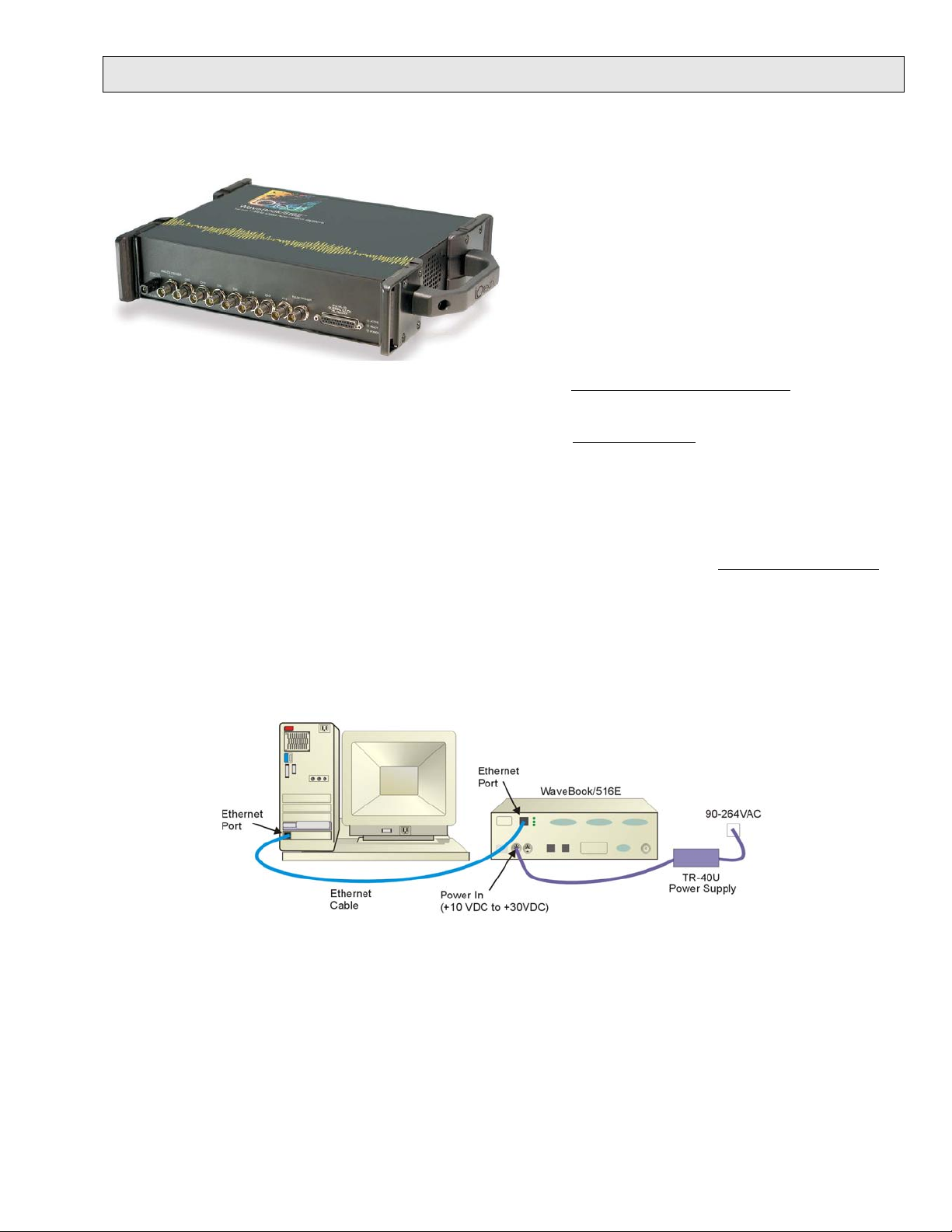
Step 2 - Connect the WaveBook/516E to the Ethernet
In this scenario a WaveBook/516E is connected directly to an Ethernet port on a host computer. Please consult your
user’s manual (located in PDF format on the CD) should you need information regarding other network types.
1. Connect the Ethernet cable to the WaveBook/516E Ethernet jack on the unit’s rear panel.
2. Connect the other end of the Ethernet cable to the Ethernet jack on the host computer or
network hub.
Step 3 - Connect the WaveBook/516E to Power
1. With the WaveBook/516E power switch “OFF,” connect the power supply cable from the TR-40U to the
WaveBook’s Power-In DIN5 connector (located on the rear panel).
2. Connect the TR-40U plug to a standard AC outlet; and turn the WaveBook’s power switch to “ON.”
489-0940, rev 2.0 324604B-01 Printed in Hungary
Page 10
Step 4 - Configure Computer Network Settings
Note: We recommend that you discuss this procedure with your Network Administrator before proceeding.
1. Open the Control Panel by navigating from the Windows Desktop as follows:
Start Menu ⇒ Settings ⇒ Control Panel.
2. Double-click the “Network Connections” icon.
3. Double-click the icon for the network that the WaveBook/516E is connected to.
4. In the “Local Area Connection Status” box, click on the <Properties> button. The “Local Area Connection
Properties” box will appear.
5. Double-click the “Internet Protocol (TCP/IP)” component. The “Internet Protocol (TCP/IP) Properties” box
will appear.
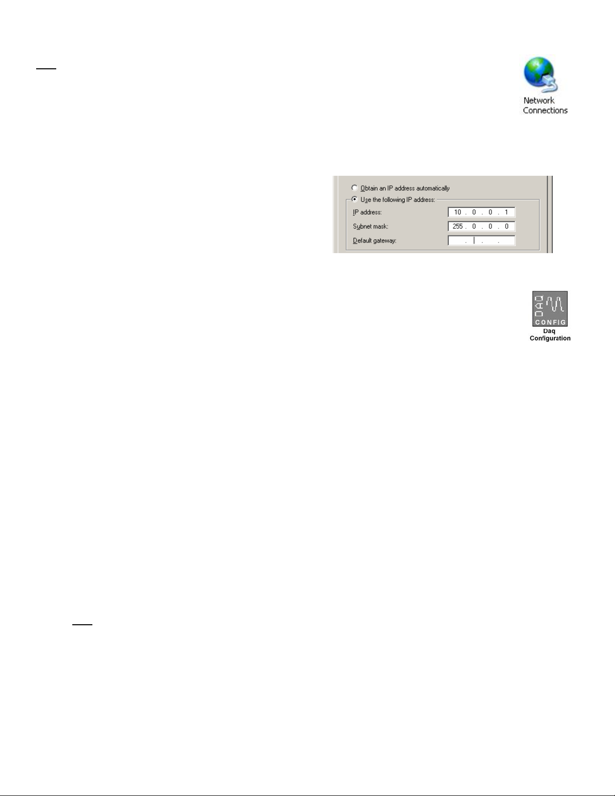
6. Select the “Use the following IP Address” radio
button. (See figure at left).
7. Set the IP address field to 10.0.0.x
where x is some number from 1 to 254.
Make sure that each computer and each device on
the dedicated network has a unique IP address.
8. Set the Subnet mask to 255.0.0.0. Note that the
remaining fields can be left as is. Click <OK>.
9. Click <OK> on follow-up screens to exit.
Internet Protocol (TCP/IP) Properties
(Partial View)
Step 5 - Configure & Test the System
1. Open the Daq Configuration Applet.
a. Navigate from the Windows’ Desktop: Start Menu ⇒ Settings ⇒ Control Panel
b. From the Control Panel, double-click the Daq Configuration icon.
2. Add the WaveBook/516E to the list of installed devices.
a. Select the Computer image in the Device Inventory configuration tree.
b. Click the <Add Device> button. The “Select Device Type” box will appear.
c. Select the WaveBook/516E from the list of devices.
d. Click the <OK> button. The “Properties” box will appear for the selected device.
e. Enter the Serial Number of the WaveBook/516E. The number is on the MAC label (rear panel, upper
left). The serial number is located just below a barcode.
f. Select the “Auto IP Setting” radio button. The IP Address of the WaveBook/516E will automatically
be calculated and displayed in the IP Address field
g. Click the <OK> button.
3. Test the system connections.
a. Make sure the device has been properly installed and is powered-on.
b. Make sure all cables are properly and securely connected.
c. Click the “Test Hardware” tab.
d. Click the <TCP/IP Test> button. This tests the Transmission Control Protocol / Internet Protocol.
e. Upon completion of the TCP/IP test, click the <Resource Test> button.
When testing, if the unit does not respond within 30 seconds perform the following steps:
1) reboot the system, 2) upon power-up, re-open the Daq Configuration applet, 3)select another
configuration setting, 4) reinitiate the test.
Step 6 - Connect Data Acquisition Signal Lines
Prior to making signal connections review the Specifications chapter of your user’s manual to ensure that your
intended signal inputs do not exceed the specified limits. The manual is included in PDF format on your CD.
Note: WaveView users only: If TEDS (Transducer Electronic Data Sheet) applies to your system,
use:
D7DB1F527813 as the Authorization Code, when prompted.
*324604B-01*
324604B-01
IOtech, 25971 Cannon Road, Cleveland, OH 44146-1833
Ph: (440) 439-4091 Fax: (440) 439-4093 productsupport@iotech.com Internet: www.iotech.com
Printed in Hungary
Page 11
WaveBook /512A /516A Quick Start
Portable Waveform Acquisition Systems
Before you get started
Verify that you have the following items.
•
WaveBook/512A or /516A
•
TR-40U Power Supply
•
Parallel Port-to-Parallel Port Cable
•
Software CD
Dynamic Signal Analysis CD (for eZ-Software*), or
Data Acquisition CD (for WaveView) See Note, pg. 2
•
License Keys for purchased [eZ]software
•
Monitor: SVGA, 1024 x 768 screen resolution
•
Computer that meets or exceeds the following:
™
Pentium, 1 GHz or equivalent;
Intel
WaveBook/516A
Microsoft
EPP (Enhanced Parallel Port) or
ECP (Enhanced Capabilities Port)
512 MB memory; 10 GB disk space
Step 1 - Install Software * /512A and /516A are not supported by Windows Vista.
1. Close all running applications on the host PC.
2. Insert the CD into your CD-ROM drive. An Opening Screen will appear.
®
Windows XP or 2000 Operating System*
3. Click the <ENTER SETUP> button.
4. From the hardware selection screen [which follows a licensing agreement], select the WaveBook/512A or
WaveBook/516A as applicable; then follow the on-screen instructions.
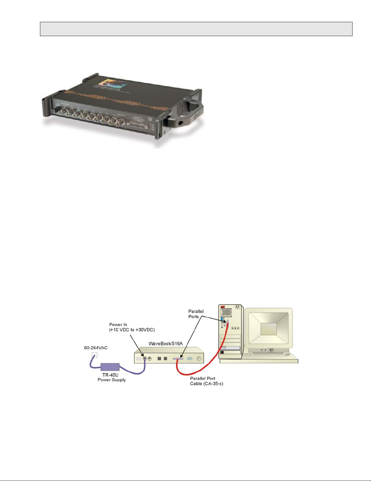
Step 2 - Connect the WaveBook to the Computer
For PCs that do not have an available parallel port, an interface option may be used, such as a WBK20A [interfaces with a
PCMCIA card slot], WBK21 [interfaces with an ISA bus slot], or WBK23 [interfaces with a PCI bus slot]. These are
discussed in PDF documents included on the CD. In regard to Ethernet connection, these WaveBook models can be
connected to one of three Expansion Ports on a WaveBook/516E or to one of three Expansion Ports on a WBK25 Ethernet
Module. Refer to the CD PDF documentation as needed.
1. Using a parallel port cable, connect the WaveBook to a parallel port on the computer.
2. With the WaveBook power switch “OFF,” connect the power supply cable from the TR-40U to the WaveBook’s
Power-In DIN5 connector (located on the rear panel).
3. Connect the TR-40U plug to a standard AC outlet; and turn the WaveBook power switch to “ON.”
489-0941, rev 2.0 324605B-01 Printed in Hungary
Page 12
Step 3 - Configure & Test the System
Step 3 - Configure & Test the System
with the Daq Configuration Applet
1. Open the Daq Configuration Applet. 1. Open the Daq Configuration Applet.
2. Add the WaveBook/512A or WaveBook/516A to the list of installed devices. 2. Add the WaveBook/512A or WaveBook/516A to the list of installed devices.
3. Test the System 3. Test the System
with the Daq Configuration Applet
a. Open the Control Panel by navigating from the Windows’ Desktop:
a. Open the Control Panel by navigating from the Windows’ Desktop:
Start Menu ⇒ Settings ⇒ Control Panel
Start Menu ⇒ Settings ⇒ Control Panel
b. From the Control Panel, double-click the Daq Configuration icon. b. From the Control Panel, double-click the Daq Configuration icon.
a. Click the <Add Device> button. The “Select Device Type” box will appear. a. Click the <Add Device> button. The “Select Device Type” box will appear.
b. Select the WaveBook/512A [or /516A], as applicable, from the list of devices. b. Select the WaveBook/512A [or /516A], as applicable, from the list of devices.
c. Click the <OK> button. The “Properties” box will appear for the selected device.
c. Click the <OK> button. The “Properties” box will appear for the selected device.
Click the “Test Hardware” tab and run the test. Should you need additional help, please refer to the user’s
Click the “Test Hardware” tab and run the test. Should you need additional help, please refer to the user’s
manual PDF included on the CD.
manual PDF included on the CD.
When testing, if the unit does not respond within 30 seconds, perform the following: 1) reboot the system, 2)
When testing, if the unit does not respond within 30 seconds, perform the following: 1) reboot the system, 2)
upon power-up, re-open the Daq Configuration applet, 3)select another configuration setting, 4) reinitiate the
upon power-up, re-open the Daq Configuration applet, 3)select another configuration setting, 4) reinitiate the
test.
test.
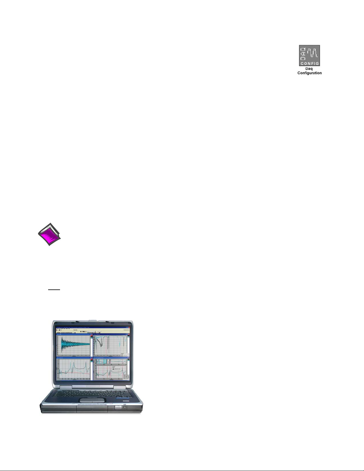
Step 4 - Connect Data Acquisition Signal Lines Step 4 - Connect Data Acquisition Signal Lines
Prior to making signal connections review the Specifications chapter of your user’s manual to ensure that your
Prior to making signal connections review the Specifications chapter of your user’s manual to ensure that your
intended signal inputs do not exceed the specified limits. The manual is included in PDF format on your CD.
intended signal inputs do not exceed the specified limits. The manual is included in PDF format on your CD.
Reference Notes:
Adobe Acrobat PDF versions of documents pertaining to the WaveBook/516E and associated
accessories and software are included on the Data Acquisition and Dynamic Signal Analysis CDs.
Documents are automatically installed onto your PC’s hard-drive as a part of product support at the time
of software installation. The default location is the Programs group. It can be accessed via the
Windows Desktop Start Menu.
Note:
WaveView users only: If you are using WaveView as your software application you will be using the Data
Acquisition CD (not the Dynamic Analysis CD). If this is the case, and if TEDS (Transducer Electronic
Data Sheet) applies to your system, use:
D7DB1F527813 as the Authorization Code, when prompted.
IOtech
25971 Cannon Road
Cleveland, OH 44146-1833
Phone: (440) 439-4091
Fax: (440) 439-4093
E-mail: sales@iotech.com
E-mail: productsupport@iotech.com
Internet: www.iotech.com
*324605B-01*
324605B-01
Printed in Hungary
Page 13

An Introduction to WaveBooks and Optional WBKs 1
What Are WaveBooks? …… 1-1
How Do the WaveBook Models Compare?…… 1-2
What Are WBKs?…… 1-3
How Do WaveBooks and WBKs Interrelate? …… 1-6
How Are WaveBook Systems Powered?…… 1-7
How Are Multiple WaveBooks Synchronized? …… 1-7
What Are WaveBooks?
WaveBooks are high-speed portable data acquisition devices that can be used in a variety of applications,
such as testing engine strain, multi-channel acoustics, mechanical integrity, and vibration/shock/strain.
WaveBook models that are discussed in this manual have the following features, with exceptions as noted:
• Power Options: Power can be supplied from an AC-to-DC adapter, battery, DBK30A rechargeable
battery module, DBK34, or DBK34A uninterruptible power supply modules.
• Easy Connection to Notebook or Desktop PCs.
• Analog Input Channels: BNC connectors keep input signals isolated from the chassis and commons.
• 16 High-Speed Digital Inputs
• Digital Signal Processing (DSP): Allows you to define a channel scan-sequence and associated gains
across all channels. Also provides for real-time digital calibration on a per-sample basis.
• Programmable Scan Sequencing: A 128-location scan sequencer allows you to program the analog
channel scan sequence, the associated unipolar/bipolar A/D range, and the input amplifier gain.
WaveBook performs 1 MHz scanning and gain switching over both its built-in and expansion
channels.
• Single, or Multi-Channel Triggering
• Pre- and Post-Trigger Readings
• Digital-Pattern Trigger: A trigger occurs when a Digital I/O pattern is equal to, not-equal to, greater
than, or less than a user-defined 16-bit digital pattern. This is useful when trying to capture noise,
vibrations or some other physical disturbance that occurs at a particular point in a digitally-sequenced
process, such as a relay-logic-control system. Trigger latency of the digital pattern trigger is less than
200 ns for post-trigger acquisitions.
• Pulse Trigger: Enables triggering and the correlation of lower-speed waveforms with the occurrence
of a user-defined, high-speed pulse.
• 20 kHz Low Pass Filters: When a PGA option is installed, eight low pass anti-alias filters are
available, one for each channel.
• External Clock Input: The external clock is useful when data collection depends on rotational speed
or axial position. Note that the external clock’s input can be set to a slower rate.
• Synchronization: The “A” and “E” Series WaveBooks include a synchronizing feature that allows
multiple WaveBook/516As, WaveBook/512As, and WaveBook/516E units to operate in sync.
• WaveBook/516E only: Includes a 10/100BaseT Ethernet connection port, which allows for a
continuous stream of data to be collected and stored in a PC.
• WaveBook/516E only: Includes 3 expansion ports for expanding the acquisition system via the built-
in parallel port interfaces of up to three other devices. For example, a WaveBook/516A could be
attached to WaveBook/516E’s Expansion Port 1, a WaveBook/512A could be attached to Expansion
Port 2, and a WBK40 Thermocouple Module could be attached to Expansion Port 3.
WaveBook/512A, /516, /516A, /516E 897995 An Introduction to WaveBooks & WBKs 1-1
Page 14
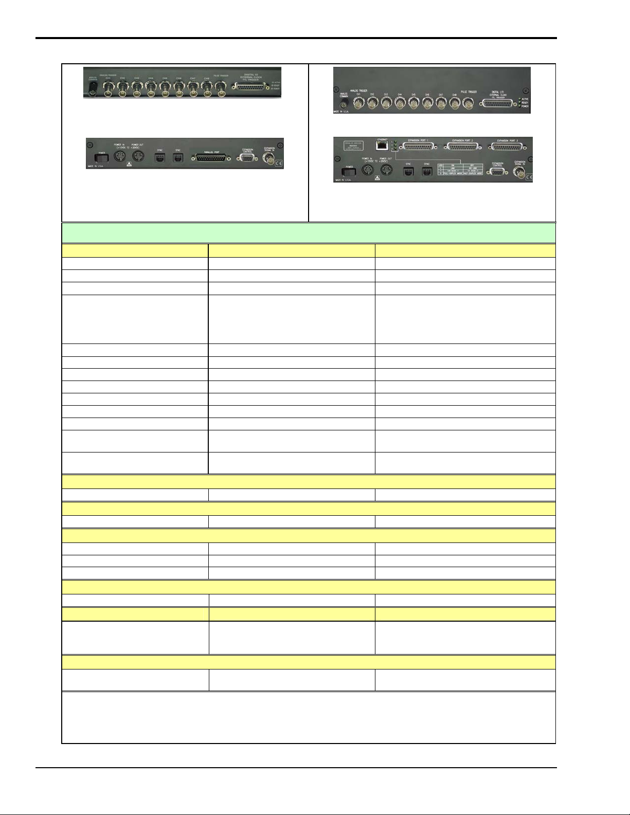
How Do the WaveBook Models Compare?
WaveBook/516A Front Panel
Note: /516 & /512A Front Panels also have this appearance.
WaveBook/516E Front Panel
WaveBook/516A Rear Panel
Note: The /512A Rear Panel also has this appearance.
The /516 Rear Panel has a Printer Pass-Thru Port
instead of two SYNC Ports.
WaveBook/516E Rear Panel
WaveBook Product Comparison
Analog Input /512A /516, /516A, /516E
A/D resolution
A/D speed
Sample rate
Ranges
Unipolar (
Bipolar
A/D accuracy
20-kHz low-pass filter
Analog input channels
Differential amplifiers
PGAs (Option)
Maximum capacity
FIFO depth
Total Harmonic Distortion
10Hz to 20Khz, Typical
Signal to Noise and Distortion
(SINAD)
Note 2)
1 (shared by all 8 inputs) 1 (shared by all 8 inputs)
1
1
High-Speed Digital Inputs
Digital I/O
External Clock / Frequency Input
32-Bit Period Measurement
Trigger
Single and multi-channel
Digital Pattern
Pulse
Synchronization
Ethernet Connection
Via a WBK25 Interface
or a connection to a WaveBook/516E
Parallel Expansion Ports
1
The THD and SINAD values apply to the -10 to +10 V range.
2
Unipolar mode does not apply when a WBK11A, WBK12A, or WBK13A is installed.
* Three parallel expansion ports are available to the WaveBook/512A, /516, and /516A when the unit is connected to a WBK25
Ethernet Interface option.
Note: Specifications are subject to change without notice.
12-bit 16-bit
1 MHz 1 MHz
1 µs/channel 1 µs/channel
0 to +2V
(Note 2)
0 to +10V, 0 to +4V,
±10V, ±5V, ±2V, ±1V
8 (1 per analog input) 8 (1 per analog input)
0 to +2V
(Note 2)
±0.03 % FS ±0.012% FS
Yes Yes
8 DE 8 DE
72 Channels 72 Channels
64K samples 64K samples
-70dB -84dB
-70dB -74dB
16 16
Yes Yes
Yes Yes
Yes Yes
Yes Yes
2 SYNC Ports 2 SYNC Ports (/516A & /516E Only)
/516E – Direct connection to Ethernet
/516 and /516A – via WBK25 Interface or a
connection to a WaveBook/516E
No* /516 and /516A – No*
0 to +10V, 0 to +4V,
±10V, ±5V, ±2V, ±1V
/516E – Yes, 3 expansion ports
1-2 An Introduction to WaveBooks & WBKs 897995 WaveBook/512A, /516, /516A, /516E
Page 15
What Are WBKs?
You can use optional modules and cards to enhance or expand your WaveBook system. These WaveBook options are
known as WBKs.
Internally, WaveBooks have room for one signal-conditioning card. Externally, you can use one or more expansion
modules.
Reference Note:
The WBK option cards and modules that follow are detailed in a companion document, the WBK Option
Cards and Modules User’s Manual, p/n 489-0902. A PDF version of the document is included on your
data acquisition CD.
WBK Options
Note: The items represented in the table are not shown to the same scale.
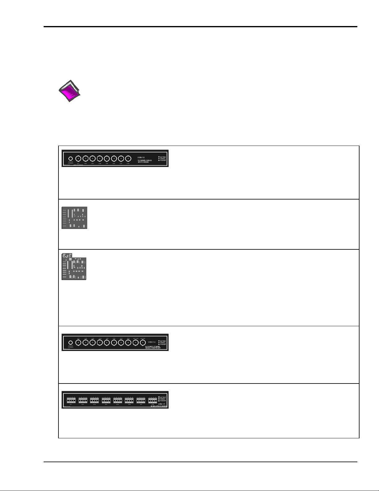
Each WBK10A module can be used to provide WaveBook with 8
additional differential-analog-inputs. The modules are equipped with
a programmable gain instrumentation amplifier (PGA) and, like the
WaveBook, each has a built-in expansion bus.
Up to eight WBK10A modules can be cascaded together for a system
capacity of 72 differential channels. Each module is capable of
supporting a WBK11A, WBK12A, or WBK13A option card.
The WBK11A card can simultaneously sample 8 channels and can
be installed inside a WaveBook or in a WBK10A module. The cards
allow for concurrent (<150 ns) capture of multiple input channels and
virtually eliminate channel-to-channel time skewing.
The WBK11A option is factory install only.
WBK10A
Analog Expansion Module
8 Channels via BNC Connectors
WBK11A
Simultaneous Sample & Hold Card (8 channels)
WBK12A
Programmable Low-Pass Filter Card
(8 channels)
WBK13A
Programmable Low-Pass Filter Card with SSH
(8 channels)
WBK14
Dynamic Signal Conditioning Module
8 Channels via BNC Connectors
WBK15
8-Slot 5B Signal Conditioning Module
8 channels via 5B Modules
WBK12A and WBK13A are 8-channel programmable low-pass filter
cards for use with WaveBook data acquisition systems. These cards
install directly into a WaveBook or WBK10A module and provide
programmable low-pass filtering over all channels. Multiple WBK12A
and WBK13A cards can be installed in one system for up to 72
channels. All of the cards’ low-pass filters and cutoff frequencies are
configured via software.
WBK13A cards have the additional capability of sampling all
channels at the same time.
The WBK12A and WBK13A options are factory install only.
The WBK14 is a dynamic analog signal input module. It enables
WaveBooks to interface with piezoelectric transducers that include
accelerometers, microphones, and force/pressure transducers.
Each WBK14 channel has a:
•
current source for transducer biasing
•
high-pass filter
•
programmable gain amplifier
•
anti-aliasing low-pass filter
•
simultaneous sample-and-hold (SSH) amplifiers
The WBK15 module provides for a diverse range of signals available
through optional 5B modules. Measurement types include: LVDT,
potentiometer, isolated current loop, ±10mV to ±40V inputs, linearized
RTD, thermocouple, frequency-to-voltage, and strain gage.
See latest catalog or contact your sales representative in regard to the
types of 5B Modules available for your application.
WaveBook/512A, /516, /516A, /516E 897995 An Introduction to WaveBooks & WBKs 1-3
Page 16
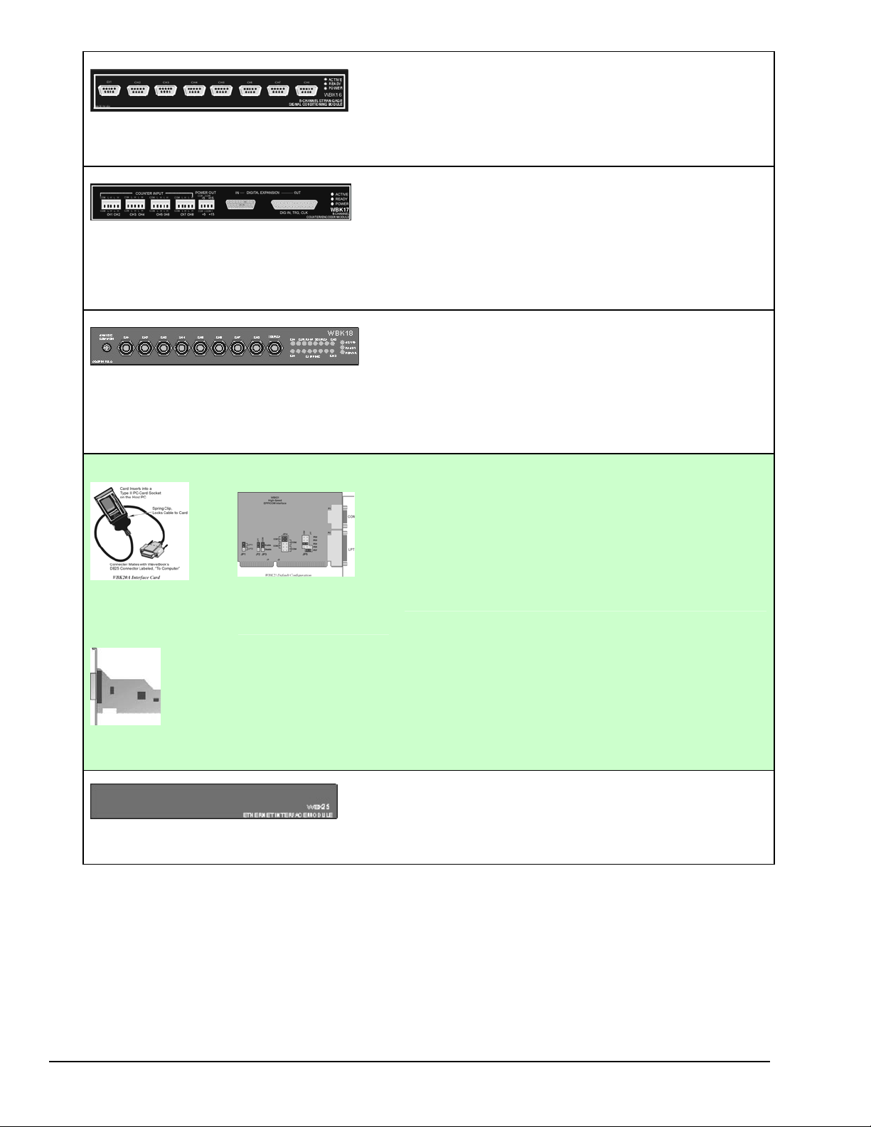
WBK16 is an 8-channel strain-gage signal-conditioning module. Up to
eight WBK16 modules (64 channels) can be accommodated by the
WaveBook and scanned at 1 µs/channel. Almost all bridge
WBK16
Strain-Gage Module
8 channels via Standard Female DB9
WBK17
Counter-Input Module with Quadrature Encoder
Support
8 channels via Removable Screw Terminal Blocks
WBK18
Dynamic Signal Conditioning Module with
Transducer Electronic Data Sheet support
(T.E.D.S).
8 channels via BNC Connectors
configurations are supported via a bridge-completion network and
software. High-gain differential-amplifier applications are also
supported. Software controls bridge configuration, gain, offset,
excitation voltage, polarity, filtering, and the calibration process.
The WBK17 is an 8-channel multi-function counter/encoder module
for use with Wavebook/512A, /516, /516A, and /516E. Each of the
high-speed, 32-bit counter channels can be configured for counter,
period, pulse width, time between edges, or encoder modes. All
channels are capable of measuring analog inputs that are digitized by
the WaveBook.
WBK18 provides 8 channels of dynamic signal input for WaveBook
systems. Each channel on the WBK18 has independent, software
control for AC or DC coupling, ICP biasing (0 or 4 mA), and low-pass
filter cut-off frequency. The 8-pole Butterworth filter on each channel
is programmable from 5 Hz to 50 kHz, in a 1-2-5 progression. The
filter can also be bypassed, resulting in a bandwidth of greater than
200 kHz.
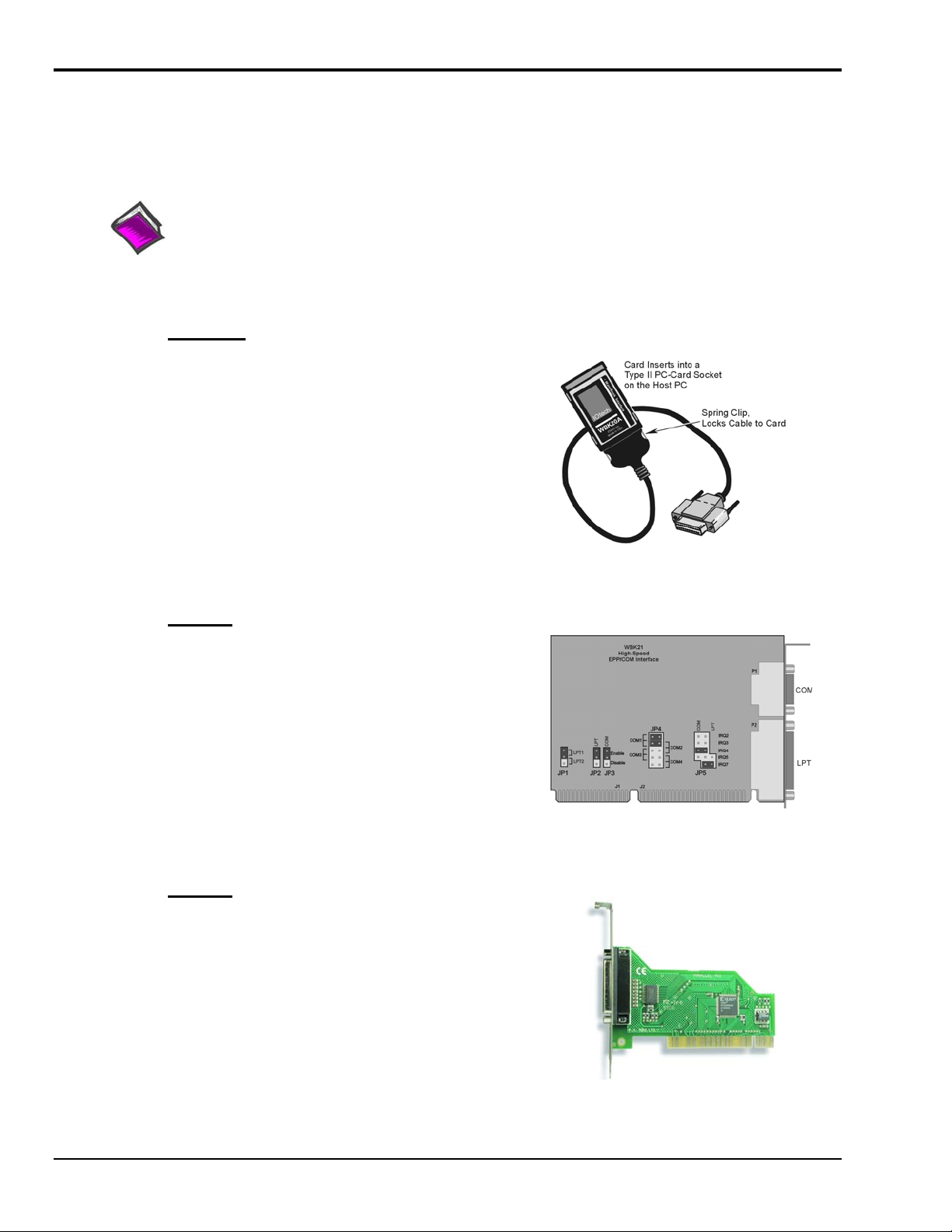
WBK20A, WBK21, and WBK23 – Three Interface options that can be used to obtain an Enhanced Parallel Port.
WBK20A
PC-Card /EPP
Interface & Cable
WBK21
ISA/EPP Interface
Plug-in Board
WBK23
PCI/EPP Interface Plug-In Board
WBK25
10/100BaseT Ethernet Interface Module
WBK20A – PCMCIA/EPP Interface Card and Cable
For linking WaveBook to a Notebook PC. This interface
provides an Enhanced Parallel Port via a PC-Card Slot.
WBK21 – ISA/EPP Interface Plug-in Board
For linking WaveBook to a desktop PC. This interface
provides an Enhanced Parallel Port via an ISA Bus-slot.
WBK23 – PCI/EPP Interface Plug-In Board
(For linking WaveBook to a desktop PC)
Provides an Enhanced Parallel Port from a PCI Bus-slot.
These three interfaces are shipped with separate documentation and
are not detailed in this manual.
The WBK25 provides high-speed Ethernet connectivity for
WaveBook, DaqBook and WBK40 series products. The WBK25
contains one 10/100BaseT Ethernet port for connection to a PC,
and three expansion ports that can attach to any model of
WaveBook, DaqBook, WBK40 Series option, or any combination
of these devices.
1-4 An Introduction to WaveBooks & WBKs 897995 WaveBook/512A, /516, /516A, /516E
Page 17
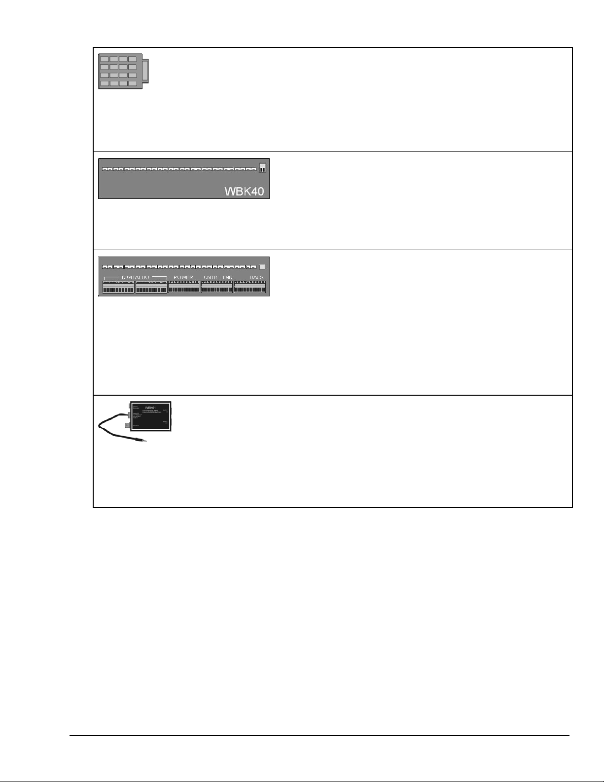
WBK30
WaveBook Memory Options
WBK40
Thermocouple Input Module
14 channels via Mini-T/C Connectors
WBK41
Multi-Function I/O Module
14 Thermocouple channels via Mini-T/C Connectors
40 Digital I/O Lines
4 Counter Inputs
2 Timer Outputs
(Optional) 4 Analog Channel Outputs
WBK30 is a DRAM-based memory board that installs inside a
WaveBook. There are three models of WBK30 available; each
significantly increases the capacity of a WaveBook's standard data
buffer of 64 K samples. Capacities are as follows:
WBK30/16 — 16 MB
WBK30/64 — 64 MB
WBK30/128 — 128 MB
Note: For WaveBook/516E the WBK30 option, if selected, must be
factory installed.
The WBK40 attaches to any one of the three expansion ports on the
WaveBook/516E or the WBK25, and provides 14 thermocouple input
channels. The 14 built-in TC channels accept any type of
thermocouple, including types J, K, S, T, E, B, R, and N. Mini-TC
connections make it quick and easy to attach thermocouples. The
WBK40 can be expanded in 14 channel increments using the DBK84
TC expansion module. A total of 15 DBK84s can be attached to one
WBK40, for a total TC channel capacity of 224 channels.
The WBK41 attaches to any one of the three expansion ports on the
WaveBook/516E or WBK25 and provides 14 thermocouple inputs, 40
digital I/O lines, 4 counter inputs, and 2 timer outputs. The WBK41
can also be supplied with an internal, 4-channel, 16-bit,
100-kHz analog output option.
The built-in TC channels on the WBK41 are accessed via mini-TC
connectors on the front panel. The counter/timer functions and 16
bits of digital I/O are accessed via removable front panel screwterminal connectors. Additional digital I/O and expansion connectors
are located at the rear of the WBK41.
The WBK41 can be easily expanded beyond its built-in channel
capacity. A maximum WBK41 system can include up to 224 TC input
channels, 272 digital I/O channels, 4 analog output channels,
4 counter input channels and 2 timer output channels.
WBK61 and WBK62
WBK61: High-Voltage Adapter with 200:1 Voltage
Divider (1 channel)
WBK62: High-Voltage Adapter with 20:1 Voltage
Divider (1 channel)
WBK61 and WBK62 are single-channel high-voltage adapters that
can be used with the WaveBook or with a WBK10A expansion
module. In addition, WBK61 and WBK62 can be used in conjunction
with WBK11A, WBK12A, and WBK13A cards.
WBK61 and WBK62 include safety-style banana-jacks for the high
and low inputs, and 60-inch (152 cm) cables with probe tips and
alligator clips for easy input connection.
WaveBook/512A, /516, /516A, /516E 897995 An Introduction to WaveBooks & WBKs 1-5
Page 18
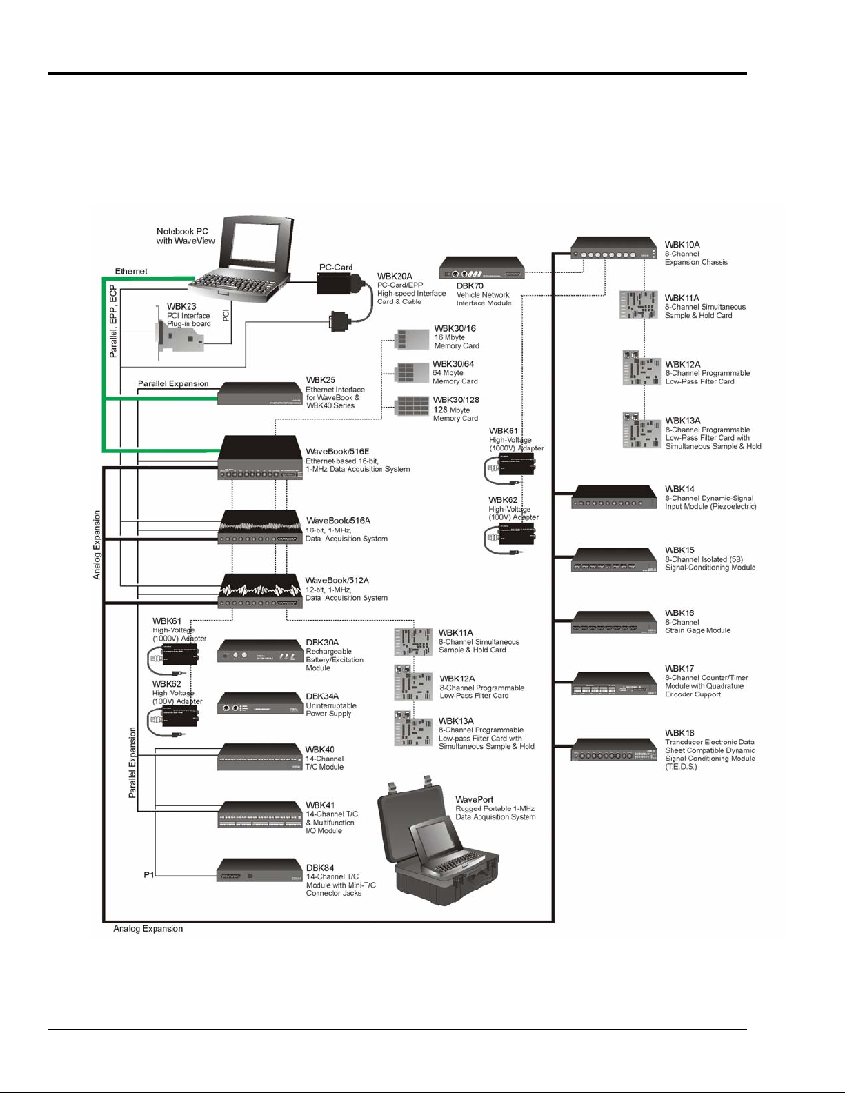
How Do WaveBooks and WBKs Interrelate?
WaveBooks and WBKs interrelate when they become part of the same data-acquisition system. The
relationship can be broken down into enhancement, expansion, or both. The following illustrates the
relationship of various system components. Detailed information and product specifications are provided
in WBK Option Cards and Modules Manual, p/n 489-0902.
WaveBook System Components
1-6 An Introduction to WaveBooks & WBKs 897995 WaveBook/512A, /516, /516A, /516E
Page 19
How Are WaveBook Systems Powered?
Power supply input voltage to the WaveBook and to the system modules, e.g., WBK10A, WBK14,
WBK15, WBK16, WBK17, WBK18, WBK40, and WBK41 must be in the range of 10 VDC to 30 VDC
and can come from an appropriate AC-to-DC adapter or a battery option. The latter includes DBK power
modules and batteries in the range of 10 VDC to 30 VDC.
Note: Power supply input to the WBK25 Ethernet Module must be in the range of 10 VDC to 30 VDC.
Available AC-to-DC adapters include the TR-40U, which has an input of 90-264 VAC and a output rating
of 2.2 amps @ 15 VDC.
Battery options include the DBK30A, DBK34A, and other 10 to 30 VDC sources, such as car batteries.
The DBK30A provides 14 VDC and when fully charged has a storage capacity of 3.4 A⋅hr; car batteries
have much higher capacities. The basic formula for battery life is:
Runtime (hr) = Battery capacity (A⋅hr) / Current load (A)
System cards, e.g., WBK11A, WBK12A, and WBK13A, get power from their host WaveBook or their
host WBK10A expansion module.
Before connecting your system to power, you need to know the power requirements of your specific
system. A calculation method that incorporates the use of worktables is presented in Chapter 2.
Reference Notes:
• Chapter 2, System Setup and Power Options, includes examples of power connections for
different WaveBook system scenarios. In these examples the included TR-40U power
adapters are used.
• Chapter 3, WaveBook Operation Reference, includes discussion of power supplies other
than the TR-40U.
How Are Multiple WaveBooks Synchronized?
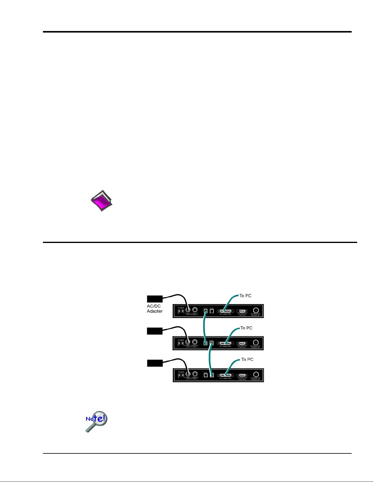
Up to four “A-series” and “E-Series” WaveBooks can be synchronized to each other via their SYNC ports.
Each unit has two identical SYNC ports. Either or both SYNC ports can be used to connect to the units via
SYNC cables CA-74-1 or CA-74-5 (1-foot or 5-foot cables, respectively). The units can be scansynchronized and triggered from any other SYNC-connected unit.
Three “A-Series” WaveBooks, Synchronized
Not all trigger modes are supported in multiple WaveBook Systems.
WaveBook/512A, /516, /516A, /516E 897995 An Introduction to WaveBooks & WBKs 1-7
Page 20

Synchronization Concept Block Diagram
The preceding diagram shows how an “A” or “E” series WaveBook can input or output synchronization
timing and trigger events on either SYNC connector.
SYNC cables are not to exceed a total combined length of 15 feet (4.57 m).
1-8 An Introduction to WaveBooks & WBKs 897995 WaveBook/512A, /516, /516A, /516E
Page 21

WaveBook/512A, /516, /516A, /516E Setup and Power Options 2
Minimum Requirements …… 2-1
Understanding WaveBook and WBK Connectors …… 2-2
Parallel Port Connections …… 2-6
Ethernet Connections …… 2-8
System Enhancement and Expansion …… 2-21
Adding WBK Option Cards …… 2-21
Adding WBK Modules…… 2-22
The Daisy-Chain Concept …… 2-26
How Channel Numbers are Determined …… 2-26
Scan Synchronization …… 2-27
Connecting the System to Power ……2-28
Calculating the System Power Requirement…… 2-28
System Power, Examples …… 2-31
Power Supplies …… 2-32
CAUTION
An incorrect use of power can damage equipment or degrade performance. Prior to connecting your
devices to power, calculate your system’s power requirements.
This chapter pertains to setting up a WaveBook system. Topics include how to: connect a WaveBook to a PC, add option
cards and modules, properly power a system, install software, and check connections using the Daq Configuration Applet. As
stated in the above Caution, you will need to calculate system power requirements prior to powering the system.
Minimum Requirements
WaveBook/516E Users
•
TR-40U Power Supply
•
Ethernet Patch Cable
•
Ethernet jack [on PC or on a hub connected to the Ethernet]
•
Software CD
Dynamic Signal Analysis CD (for eZ-Software*), or
Data Acquisition CD (for WaveView) See Note A
•
License Keys for purchased [eZ]software
•
Monitor: SVGA, 1024 x 768 screen resolution
•
Windows 2000 SP4 and Windows XP users:
PC with Intel™ Pentium, 1 GHz or equivalent;
512 MB memory; 10 GB disk space
• Windows Vista users:
PC must be Windows Vista Premium Ready
WaveBook/512A or /516A Users
•
TR-40U Power Supply
•
Parallel Port-to-Parallel Port Cable
•
EPP Enhanced Parallel Port or
ECP Enhanced Capabilities Port
•
Software CD
Dynamic Signal Analysis CD (for eZ-Software*), or
Data Acquisition CD (for WaveView) See Note A.
•
License Keys for purchased [eZ]software
•
Monitor: SVGA, 1024 x 768 screen resolution
•
Windows 2000 SP4 and Windows XP users:
PC with Intel™ Pentium, 1 GHz or equivalent;
512 MB memory; 10 GB disk space
Note: Windows Vista
WaveBook/516A
does not support WaveBook/512A or
Note A: WaveView users only: If you are using WaveView as your software application you will be using the
Data Acquisition CD (not the Dynamic Analysis CD). If this is the case, and if TEDS (Transducer
Electronic Data Sheet) applies to your system, use: D7DB1F527813 as the Authorization Code,
when prompted.
WaveBook User’s Manual 947191 System Setup and Power Options 2-1
Page 22
Understanding WaveBook and WBK Connectors
WaveBook/516E Front Panel
The WaveBook/516E Front Panel includes the following connectors and LED indicators.
Analog Common – banana jack receptacle
Channels 1 through 8 – BNC connectors; Channel 1 is also used for Analog Trigger
Pulse Trigger – BNC connector
Digital I/O, External Clock, TTL Trigger – DSUB25 connector
LEDs: ACTIVE – Lights when a sample has been converted by the A/D Converter.
READY – Lights when the WaveBook/516E’s internal Ethernet module establishes communication.
POWER – Lights when power is turned on and is present.
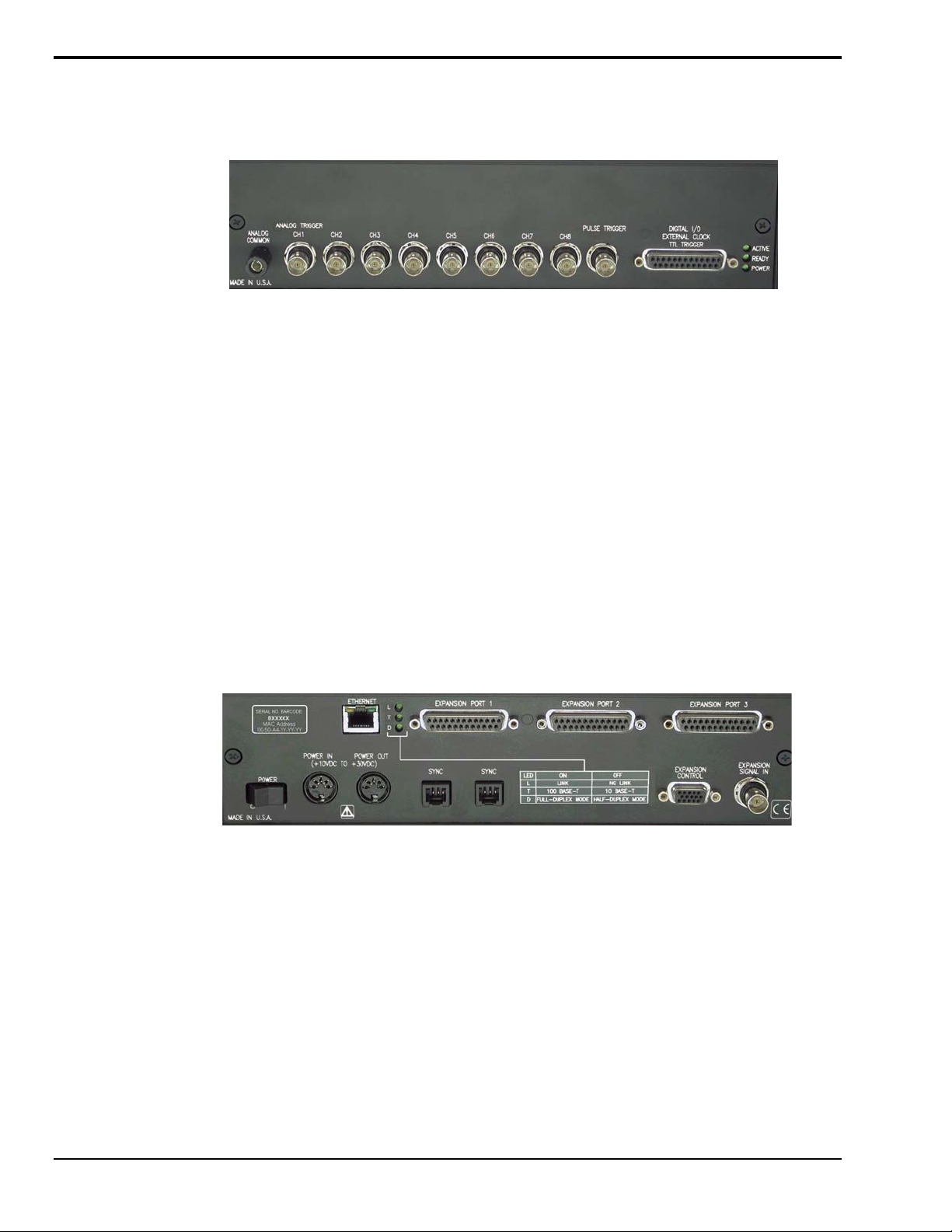
WaveBook/516E Rear Panel
The upper row of the WaveBook/516E rear panel includes a label with a barcode for the device serial
number and a MAC Address (Internet Protocol Address). The row also has an Ethernet Port, three LEDs
(designated L, T, and D), and three Expansion Ports. The panel’s lower row includes a Power Switch,
one DIN5 Power In connector, one DIN5 Power Out connector, two SYNC (synchronization ports), an
LED legend, a 15 pin Expansion Control connector, and a BNC Expansion Signal In connector.
Additional detail follows. Items described below are done so from left to right, when looking at the rear
panel.
MAC Address Label: The Media Access Control (MAC) label is located in the upper left corner of the
rear panel. The label shows the device serial number in barcode and base 10 formats. It also shows the
Ethernet address (MAC Address) which is derived from the serial number in hexadecimal. If prompted to
enter a serial number in software, use the base 10 number. Conversion to a hexadecimal number for use
in addressing will be automatic.
Note: If your network administrator asks you for a MAC number or MAC Address, provide him [or her]
with the hexadecimal number that is located at the bottom of the label.
ETHERNET: The 10/100BaseT Ethernet port can connect to the Ethernet port of the host PC, or to an
Ethernet network. Either of two Ethernet patch cables may be used to make the connection. CA-242 is a
1.5 foot cable. CA-242-7 is a 7-foot cable. Note that the Ethernet connector has two built in LEDs that
indicate traffic flow. These are discussed with the three other Ethernet-related LEDs. Note that the
Ethernet cable length must be <10m in order for the system to be CE Compliant.
2-2 System Setup and Power Options 947191 WaveBook User’s Manual
Page 23

LEDs: There are 5 ETHERNET Status LEDS. Two rectangular LEDs (Tx and
Rx) are built into the frame of the Ethernet jack. The other three LEDs,
located just to the right of the jack, are round and are labeled L, T, and
D.
Tx – “ON” indicates traffic is being transmitted (see figure at right).
Rx – “ON” indicates that the port is receiving traffic.
L (Link) “ON” indicates a link exists. “OFF” indicates no link.
T (BaseT) “ON” indicates 100BaseTx, “OFF” indicates 10BaseT.
D (Duplex) “ON” indicates full duplex, which allows simultaneous two-
way data traffic. “OFF” indicates half-duplex, which only
allows one-way data traffic at any given time.
EXPANSION PORTS [1, 2, and 3]: used to expand the system with up to three additional devices.
Each Expansion Port can be used to connect the WaveBook/516E to the PARALLEL PORT connector of
a WaveBook/516A, WaveBook/512A, WaveBook/516, WBK40, or WBK41.
POWER Switch: A rocker-type switch with a “0” label for Power Off, and a “1” for Power On.
POWER IN: +10 VDC to +30 VDC, through a socket type DIN5 connector on the chassis.
Power is typically supplied from a TR-40U power adapter.
POWER OUT: +10 VDC to +30 VDC, through a socket type DIN5 connector on the chassis.
Power can be supplied from the WaveBook/516E to another device in the system, in which case, the
power cable would connect the receiving device’s POWER IN DIN5 connector. A current limit of 5
amps is not to be exceeded.
Calculate system amp load prior to creating a system daisy-chain. Although WaveBook
device connectors and CA-115 power cables have 5 amp limits, TR-40Us are limited to
2.2 amps. Tables for determining amp load are provided in an upcoming section,
entitled Calculating the System Power Requirement.
Tx and Rx LEDs
SYNC (Qty of 2) – Two “synchronization ports” provide a means of synchronizing up to four
WaveBook “A” and/or “E” units in regard to post-trigger scanning. The ports accept CA-74-1 (1 foot)
and CA-74-5
(5 foot) cables. Both are 6-conductor RJ-11 cables.
Up to four units can be synchronized. The total combined length of the SYNC cables is
not to exceed 15 feet (4.57 m).
EXPANSION CONTROL: The HD15 EXPANSION CONTROL connector provides a means of
connecting a control output signal [from the WaveBook/516E] to the 15HD EXPANSION CONTROL IN
connector of the first WBK expansion device in the system. Expansion Control signal lines can be daisychained, as will be seen in upcoming system examples.
EXPANSION SIGNAL IN: This BNC connector provides a way for the WaveBook/516E to receive
return signals from the EXPANSION SIGNAL OUT BNC connector of the first WBK expansion device
in the system. Expansion Signal lines can be daisy-chained, as will be seen in upcoming system
examples.
WaveBook User’s Manual 947191 System Setup and Power Options 2-3
Page 24
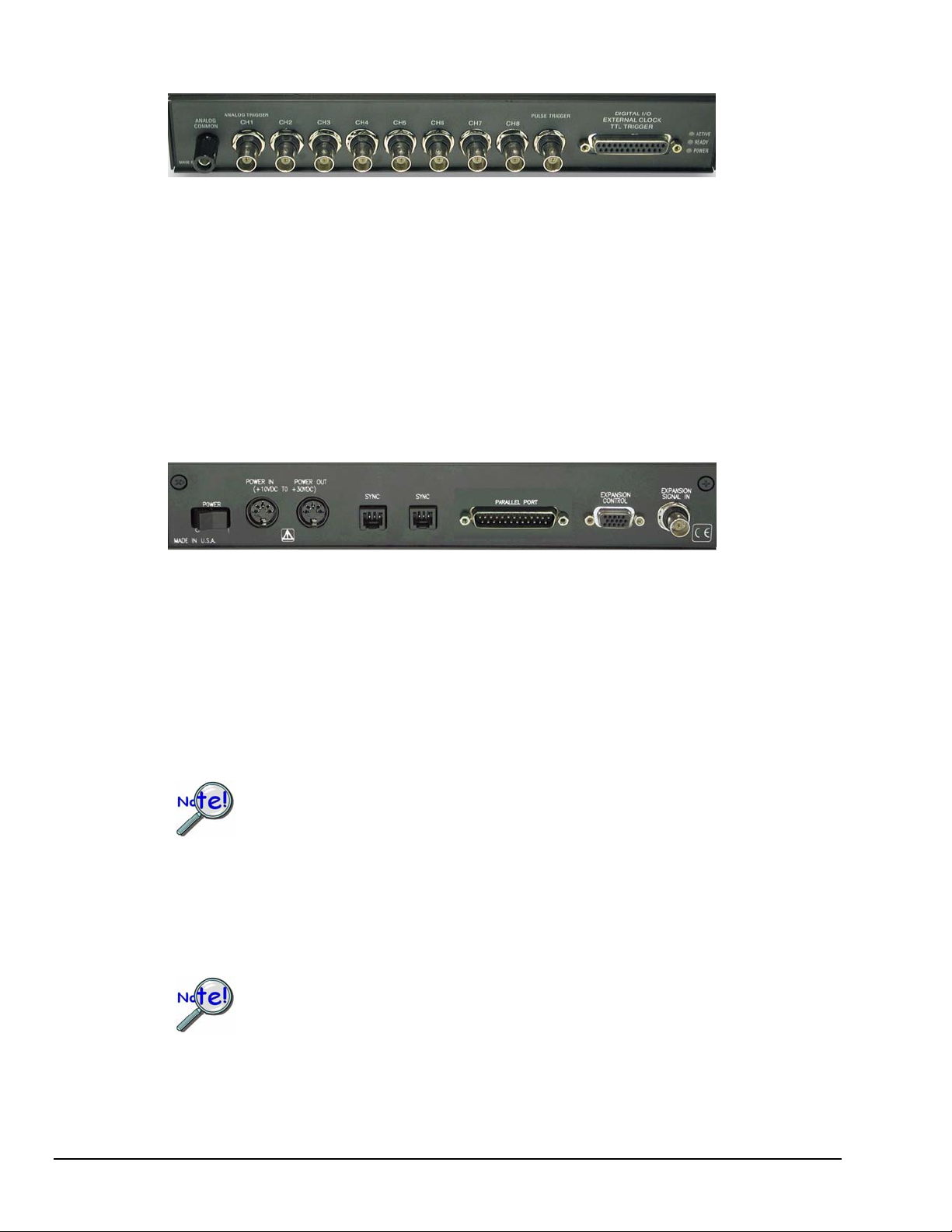
WaveBook/512A, /516, and /516A Front Panels
The front panel for each of these three units includes the following connectors and LED indicators.
Analog Common – banana jack receptacle
Channels 1 through 8 –BNC connectors; Channel 1 is also used for Analog Trigger
Pulse Trigger – BNC connector
Digital I/O, External Clock, TTL Trigger – DSUB25 Connector
LEDs: ACTIVE – Lights when a sample has been converted by the A/D Converter.
READY – Lights when an appropriate parallel port protocol has been established with the unit.
POWER – Lights when power is turned on and is present.
WaveBook/512A, /516, and /516A Rear Panels [WaveBook/516A Rear Panel Shown]
Note: WaveBook/516 has no SYNC ports. In their place is a DB25S connector that serves
as a printer pass-through.
POWER Switch: A rocker-type switch with a “0” label for Power Off, and a “1” for Power On.
POWER IN: +10 VDC to +30 VDC, through a socket type DIN5 connector on the chassis.
Power is typically supplied from a TR-40U power adapter.
POWER OUT: +10 VDC to +30 VDC, through a socket type DIN5 connector on the chassis.
Power can be supplied from the WaveBook/516E to another device in the system, in which case, the
power cable would connect the receiving device’s POWER IN DIN5 connector. A current limit of 5
amps is not to be exceeded.
Calculate system amp load prior to creating a system daisy-chain. Although WaveBook
device connectors and CA-115 power cables have 5 amp limits, TR-40Us are limited to
2.2 amps. Tables for determining amp load are provided in an upcoming section,
entitled Calculating the System Power Requirement.
SYNC (Qty of 2) – “A” and “E” units only. Two “synchronization ports” provide a means of
synchronizing up to four WaveBook “A” and/or “E” units in regard to post-trigger scanning. The SYNC
ports accept CA-74-1 and CA-74-5 cables. Both are 6-conductor, RJ-11 cables.
Note: WaveBook/516 has no SYNC ports. In their place is a DB25S connector that serves as a printer
pass-through.
Up to four units can be synchronized. The total combined length of the SYNC cables is
not to exceed 15 feet (4.57 m).
2-4 System Setup and Power Options 947191 WaveBook User’s Manual
Page 25
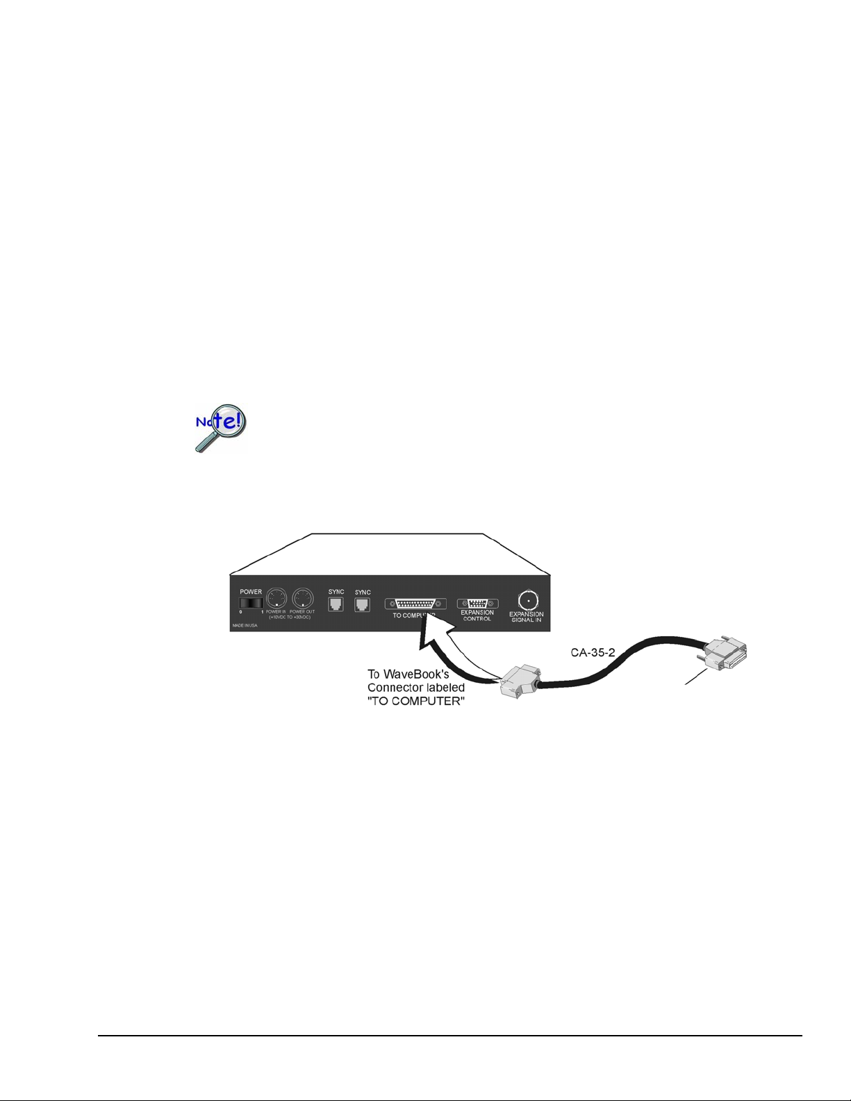
PARALLEL PORT: WaveBook/512A, /516, and /516A can be connected to a PC’s Parallel Port or to
an Ethernet. In regard to Parallel Port connection, use of an Enhanced Parallel Port (EPP) or an Extended
Capabilities Port (ECP) is recommended. Three WBK options, WBK20A, WBK21, and WBK23 are
available for use with PCs that do not have Enhanced Parallel Ports and are discussed on page 2-6. With
exception of the WBK20A, which has its own cable, when this type of connection is desired, a 2-foot
CA-35-2, or a 6-foot CA-35-6 communication cable is used to connect the WaveBook to the host PC.
In regard to Ethernet connection, the WaveBook can be connected to one of three Expansion Ports on a
WaveBook/516E or to one of three Expansion Ports on a WBK25 Ethernet Module.
EXPANSION CONTROL: The HD15 EXPANSION CONTROL connector provides a means of
connecting a control output signal [from the WaveBook/516E] to the 15HD EXPANSION CONTROL IN
connector of the first WBK expansion device in the system. Expansion Control signal lines can be daisychained, as will be seen in upcoming system examples.
EXPANSION SIGNAL IN: This BNC connector provides a way for the WaveBook/516E to receive
return signals from the EXPANSION SIGNAL OUT BNC connector of the first WBK expansion device
in the system. Expansion Signal lines can be daisy-chained, as will be seen in upcoming system
examples.
To ensure EPP speeds are properly handled, it is important that WaveBook systems make
use of a 1284-compliant cable. Standard parallel cables will not work properly, primarily
due to a lack of shielding. Note that CA-35-12 (1 foot), CA-35-2 (2-foot), and
CA-35-6 (6 foot) cables are 1284-compliant.
Use of the CA-35-12 cable will result in less noise due to its shorter length.
WaveBook/516A
To a PC Parallel Port or to one of 3
Expansion Ports on a WaveBook/516E
or WBK25 Ethernet Interface Module.
Connecting the Communication Cable (CA-35-2) to a WaveBook/516A
WaveBook User’s Manual 947191 System Setup and Power Options 2-5
Page 26
Parallel Port Connections
Note: If you do not need to add a parallel port, skip this parallel port section.
If you need to connect a WaveBook/512A, /516, or /516A to a notebook or desktop PC that lacks a parallel port,
you can use an interface device to obtain a port. To do so, your PC needs to have an available PC-Card Slot, ISA
Bus Slot, or a PCI Bus Slot. You can use one of the following devices, depending on which interface is needed.
Reference Note:
You will need to use the Daq Configuration Applet to set the parallel port system devices. Appendix A,
Using the Daq Configuration Applet, contains instructions for opening the applet and configuring devices.
Appendix B, TCP/IP and Resource Tests, provides instructions for using the Daq Configuration Applet to
test the system.
WBK20A
For Interfacing with a PC-Card Slot
If you need to connect your WaveBook/512A, /516,
or /516A to a notebook PC that has no available
parallel port, you can use a WBK20A. The device
consists of a PCMCIA Interface Card, cable, and
DB25 Connector.
Refer to separate instructions [supplied with the
WBK20A] if applicable.
WBK21
For Interfacing with an ISA Bus Slot.
WBK20A, Plugs into a PC-Card Slot
If you need to connect your WaveBook/512A, /516,
or /516A to a desktop PC that has no available
parallel port, you may be able to use the WBK21
option to provide a port. The board’s connector is
labeled LPT. WBK21 plugs into and ISA Bus Slot.
Refer to separate instructions [supplied with the
WBK21] if applicable.
WBK21, Plugs into an ISA Bus Slot
WBK23
For Interfacing with a PCI Bus Slot.
If you need to connect your WaveBook/512A,
/516, or /516A to a desktop PC that has no
available parallel port, you may be able to use a
WBK23 to provide a port. The WBK23 plugs into
a PCI Bus Slot.
Refer to separate instructions [supplied with the
WBK23] if applicable.
WBK23, Plugs into a PCI Bus Slot
2-6 System Setup and Power Options 947191 WaveBook User’s Manual
Page 27

WBK25
For interfacing with an Ethernet jack on a
PC or on a network hub.
If you are using a PC or a network with an
available Ethernet jack you can obtain three
parallel ports by using a WBK25 Ethernet-toParallel Port Interface.
The WBK25 provides high-speed Ethernet
connectivity for WaveBook, DaqBook, WBK40,
and WBK41 systems. Connection to the Ethernet
is made via an Ethernet patch cable, which links the
WBK25’s 10/100BaseT Ethernet port to a PC’s
Ethernet jack or an Ethernet network hub.
Refer to separate instructions [supplied with the WBK25] if applicable.
WBK25’s three parallel ports are labeled as expansion ports 1 through 3. They are
used to connect to WaveBook, DaqBook, WBK40, and WBK41 systems via parallel
cables. The ports cannot be used for other parallel devices, such as printers and
scanners.
The WBK25 Ethernet-to-Parallel Port Interface
connects to the Ethernet and provides three
parallel ports.
WaveBook User’s Manual 947191 System Setup and Power Options 2-7
Page 28

Ethernet Connections
DaqBook/2000E
WaveBook/516E
Connecting a DaqBook/2000E to the Ethernet
The WaveBook/516E connects in the same manner.
You can connect a WaveBook/516E directly to an Ethernet port on a PC or network hub, via the unit’s
built-in 10/100BaseT Ethernet interface. An Ethernet patch cable CA-242 (1.5 foot) or CA-242-7 (7 foot)
cable is used to make the connection. Note that either a straight-through or a cross-over cable may be used.
The circuitry automatically adjusts for the cable type to ensure proper connection.
Two methods of connecting a WaveBook/512A, /516, or /516A to the Ethernet are available. These are (1)
connect the unit to a WaveBook/516E, or (2) connect the unit to a WBK25 Ethernet Interface Module. In
both scenarios the DB25 Parallel Port of the WaveBook/512A, /516, or /516A device connects to one of
three Expansion Ports located on the WaveBook/2000E [or on the WBK25]. The connection would be
made with a CA-35-2 (2-foot) or a CA-35-12 (1-foot) cable.
Note: For the most part, the following Ethernet instructions apply to both WaveBook and DaqBook
Ethernet applications, with exceptions as noted. For illustrations or screen shots representing a
DaqBook/2000E, note that WaveBook/516E also applies, unless implied otherwise.
The DaqBook/2000E and WaveBook/516E connect directly to an Ethernet port [on a PC or network hub]
via the unit’s built-in 10/100BaseT Ethernet interface. An Ethernet patch cable CA-242 (1.5 foot) or
CA-242-7 (7 foot) cable is used to make the connection.
2-8 System Setup & Power Options Connecting to the Ethernet
Page 29
CAUTION
Turn off power to the system devices and externally connected equipment before connecting cables.
Electric shock or damage to equipment can result even under low-voltage conditions.
Take ESD precautions (packaging, proper handling, grounded wrist strap, etc.)
Reference Note: Adobe PDF versions of user manuals will automatically install onto your hard drive as a
part of product support. The default location is in the Programs group, which can be accessed from the
Windows Desktop. You can also access documents directly from the data acquisition CD via the <View
PDFs> button located on the CD’s opening screen.
STEP 1 – Install the Software
1. Remove previous version Daq drivers, if present. You can do this through Microsoft’s Add/Remove
Programs feature.
2. Place the Data Acquisition CD into the CD-ROM drive. Wait for PC to auto-run the CD. This may take a
few moments, depending on your PC. If the CD does not auto-run, use the Desktop’s Start/Run/Browse
feature to locate and run Setup.exe [from the applicable CD-ROM drive].
3. After the intro-screen appears, follow the screen prompts.
2-9 System Setup & Power Options 947191 Connecting to the Ethernet
Page 30
Some network devices such as a wireless access point may act as a DHCP server. If this is
the case, follow the instructions for the LAN with a DHCP server. For detailed information
consult the documentation that is specific to your network device.
STEP 2 – Determine the type of Network Connection
To properly connect and configure a DaqBook/2000E or a WaveBook/516E, you must determine the type
of network that the device will become part of. This is because the type of network used has a direct
bearing on the IP address of the device.
Briefly, the four network types are as follows:
Dedicated Network - with a direct cable connection from the PC to the device
Dedicated Network - making use of a network hub or switch
LAN with a DHCP server
(Local Area Network with a Dynamic Host Configuration Protocol)
LAN without a DHCP server
(Local Area Network with no Dynamic Host Configuration Protocol)
Brief descriptions and illustrations follow.
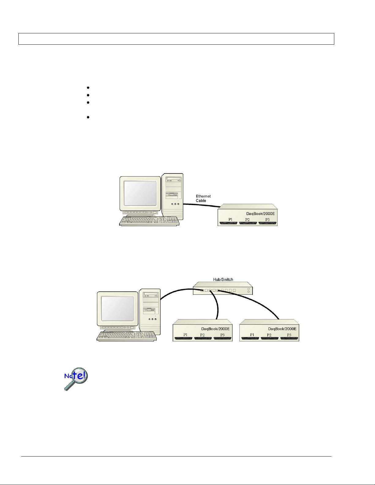
Dedicated Network - with a direct cable connection from the PC to the device
In this scenario a DaqBook/2000E or a WaveBook/516E is connected directly to an Ethernet jack on a host
computer.
Dedicated Network using a Direct Cable Connection
Dedicated Network - making use of a network hub or switch
In this scenario the DaqBook/2000E or WaveBook/516E connects to the Ethernet through a network hub or
switch. At least one computer is also connected to the hub.
Dedicated Network using a Hub/Switch
2-10 System Setup & Power Options Connecting to the Ethernet
Page 31

LAN with a DHCP Server (Local Area Network with a Dynamic Host Configuration Protocol server)
Many corporations use the LAN/Server with DHCP arrangement for their networks. In this type of setup
several computers are typically connected to a network that makes use of a DHCP server. In addition, a
DaqBook/2000E or WaveBook/516E is connected to the network hub/switch.
LAN with a DHCP Server
Notes:
Using a DaqBook/2000E or WaveBook/516E on a typical LAN may affect the speed of the network
and internet data transfer. Because of this we recommend adding a network card to the computer and
using one of the two dedicated network configurations.
Contact your network administrator before connecting a DaqBook/2000E or a WaveBook/516E
to a corporate network.
LAN with no DHCP Server
(Local Area Network with no Dynamic Host Configuration Protocol server)
This scenario looks the same as that shown in the previous illustration, except there is no Dynamic Host
Configuration Protocol (DHCP). In this type of setup, one or more computers are connected to a network;
and each computer has a static IP address.
2-11 System Setup & Power Options 947191 Connecting to the Ethernet
Page 32

Reference Note:
For examples of WaveBook system connections, including cable use, refer to the System Enhancement
and Expansion section of this chapter. The section begins on page 2-21.
When powering up a WaveBook system it is important that the WaveBook/516E (or WBK25) is
powered last, and that the most remote system components are powered first. Other power-up
sequences will result in software’s failure to recognize all components. *
First, power-on the WBK expansion modules.
Second, power-on WaveBooks or WBK modules that are connected to the expansion
ports of the WaveBook/516E or WBK25.
Finally, power-on the WaveBook/516E and/or WBK25 devices.
* An exception to this power-up scheme is to power-on the entire system at once.
Reference Notes:
The section System Enhancement and Expansion (which begins on page 2-21) contains
several examples, which include power connections.
The section entitled, Connecting the System to Power (page 2-28) should be reviewed prior to
powering up a system.
It is possible to use a VDC power source other than the commonly used switching-mode
power supply, often referred to as an adapter. However, be sure to consult the power-
STEP 3 – Connect the System Components
What you will need to connect a DaqBook/2000E or a WaveBook/516E to the Ethernet:
An available connection to the Ethernet. The connection can be either
- an Ethernet jack on a computer or
- an Ethernet jack on a hub that is connected to the Ethernet.
An Ethernet patch cable, e.g., a CA-242 (1.5 foot cable) or a CA-242-7 (7-foot cable).
1. Connect the Ethernet cable to the Ethernet jack on the DaqBook/2000E or WaveBook/516E.
2. Connect the other end of the Ethernet cable to the Ethernet jack on the host computer or
network hub.
STEP 4 – Power-up the System Components
What you will need:
A power supply with a range of +10 VDC to +30 VDC.
The power supply needs to have a male DIN5 connector.
Note: The switching-mode power supply that is commonly used with these systems has an input
range of 100 VAC to 240 VAC at 50 Hz to 60 Hz. The power supply’s output [to the
device] is typically 15 VDC @ 2.7 amps via a DIN5 connector.
Note: Various AC adapter models support power grids of USA, Europe, Japan, and Asia.
related sections of this chapter, which begin on page 2-28 before doing so.
2-12 System Setup & Power Options Connecting to the Ethernet
Page 33

Reference Note:
Refer to the power-related sections of this manual before powering up a system. The sections
begin on page 2-28.
How to make the connection:
1. Using the unit’s power switch, turn the DaqBook/2000E or WaveBook/516E “OFF.
The switch will be in the “0” position and the power LED will be unlit.
2. Connect the DIN5 end of the adapter’s cable to the power in connector on the DaqBook/2000E
or WaveBook/516E.
3. Connect the adapter’s plug to a standard AC outlet.
4. If your adapter has a power switch, position it to “ON.”
5. Turn ON the DaqBook/2000E or the WaveBook/516E by placing the power switch to the
“1” position. The power led will light up.
2-13 System Setup & Power Options 947191 Connecting to the Ethernet
Page 34

If using a LAN (Local Area Network), which has a DHCP server, skip this section and continue
with STEP 7 - Configure and Test the System using the Daq*Configuration Applet (page 2-18).
If using a LAN (Local Area Network), which has no DHCP server, skip this section and
continue with STEP 6 - Configure Device Network Settings using DaqIPConfig (page 2-17).
Local Area Connection Status
4. In the “Local Area Connection Status” box (previous figure), click on the <Properties> button.
The “Local Area Connection Properties” box will appear (following figure).
STEP 5 - Configure the Computer’s Network Settings [Applies to “dedicated networks” only]
1. Open the Control Panel by navigating from the Windows Desktop as follows:
Start Menu Settings Control Panel.
2. Double-click the “Network and Dial-up Connections” icon.
3. Double-click the “Network Connection” icon for the network that the DaqBook/2000E or the
WaveBook/516E is connected to.
2-14 System Setup & Power Options Connecting to the Ethernet
Page 35

2-15 System Setup & Power Options 947191 Connecting to the Ethernet
Local Area Connection Properties
5. Double-click the “Internet Protocol (TCP/IP)” component (previous figure).
The “Internet Protocol (TCP/IP) Properties” box will appear (following figure).
Internet Protocol (TCP/IP) Properties
Page 36

Internet Protocol (TCP/IP) Properties
Configure the Computer’s TCP/IP settings as follows.
6. Select the “Use the following IP Address” radio button.
7. Set the IP address field to 10.0.0.x where x is some number from 1 to 255.
Make sure that each computer on the dedicated network has a unique IP address!
8. Set the Subnet mask to 255.0.0.0. Note that the remaining fields can be left unchanged.
2-16 System Setup & Power Options Connecting to the Ethernet
Page 37

If using a LAN (Local Area Network), which has a DHCP server, skip this section and continue
with STEP 7 - Configure and Test the System using the Daq*Configuration Applet (page 2-18).
STEP 6 - Configure Device Network Settings using DaqIPConfig
Applies only to a LAN (Local Area Network), which has a no DHCP server.
The DaqIPConfig applet is designed for 32-bit Windows/2000/XP/Vista systems. You can use DaqIPConfig to
change the IP address of the device to be compatible with networks that require fixed IP addresses. As a precaution,
you should always consult with your IT administrator before using the applet to ensure that each device and host
computer connected to the network maintains a unique IP address. The applet is located in the program group for
the associated device and can be accessed from the Windows Desktop via the start menu.
1. Locate the DaqIPConfig Applet.
Locate the DaqIPConfig applet by navigating from the Windows’ Desktop as follows:
DaqBook Users: Start Menu Programs IOtech DaqX Software DaqIPConfig
WaveBook Users: Start Menu Programs IOtech WaveBook Software DaqIPConfig
2. Open the DaqIPConfig Applet.
Click on the DaqIPConfig selection to open the applet.
DaqIPConfig
3. Select the device that is to have the address change.
Note: In the above figure there is only one device to select, i.e., DaqBook/2000E.
4. Set the internet protocol (TCP/IP) settings to be compatible with host computer.
(a) Select the radio button labeled “Use the following IP address.”
(b) Enter the new internet protocol settings. If needed, consult your network administrator for
acceptable numbers. Do not set the TCP/IP to the computer’s IP address!
(c) Click the <OK> button.
5. Reboot the device.
The new IP address will not take affect until the device has been powered-off, then powered back on.
6. Repeat steps 3, 4, and 5 for other devices in the system.
After configuring the network settings for all devices, proceed to Step 7.
2-17 System Setup & Power Options 947191 Connecting to the Ethernet
Page 38

STEP 7 - Configure and test the System using the Daq* Configuration Applet
The Daq* Configuration applet is located in the Windows Control Panel. It allows you to add or remove a
device and change configuration settings. The included test utility provides feedback on the validity of
current configuration settings, as well as performance summaries.
1. Open the Daq* Configuration Applet.
a. Open the Control Panel by navigating from the Windows’ Desktop as follows:
Start Menu Settings Control Panel
b. From the Control Panel, double-click the Daq* Configuration icon.
2. Add the first-level device to the list of installed devices.
The first-level device is the device that will be connected directly to the Ethernet, via a host computer’s
Ethernet jack or a jack on a network hub. The DaqBook/2000E and WaveBook/516E are each examples of
first-level devices.
a. Select the Computer image in the Device Inventory configuration tree (following figure).
b. Click the <Add Device> button. The “Select Device Type” box will appear.
c. Select the DaqBook2000E or the WaveBook516E from the list of devices, as applicable.
d. Click the <OK> button. The “Properties” box will appear for the selected device.
Using Daq* Configuration Device Inventory & Select Device Type to Add a Device
Note: Although the above figure indicates that a WaveBook/516E was selected as the first level
device, we could similarly have a DaqBook/2000E as the first-level device.
2-18 System Setup & Power Options Connecting to the Ethernet
Page 39

Partial View of DaqIP Config
Showing IP Addresses & Serial Numbers
Provide your network administrator with the information on the device’s MAC label.
Also, find out from the administrator if the IP Address will be changing. If so, see if you
can obtain a permanent IP Address dedicated specifically to your device.
For DEDICATED Networks
For LAN with DHCP Server Networks
Daq* Configuration, Properties Dialog Boxes
Note: The above images are based on WaveBook/516E. We could similarly have DaqBook/2000E selected.
3. Set the properties of the first-level device.
In this step you will set the device properties according to one of the following two methods, depending on
whether you have a “Dedicated Network” or a “LAN with DHCP Server Network.” Illustrations of the
network types are provided on page B-3.
Users of Dedicated Networks follow these 2 steps.
a. Enter the Serial Number of the first-level device (DaqBook/2000E, or WaveBook/516E). In
the following screen shots the Serial Number is 800000.
b. Select the “Auto IP Setting” radio button. Note that the IP Address of the DaqBook/2000E,
or the WaveBook/516E will automatically be calculated and displayed in the IP Address field
as indicated in the following left-hand figure.
c. Click the <OK> button.
Users of LAN with DHCP Server Networks follow these 3 steps.
The DaqIPConfig applet provides the Serial Number and the IP Address of the device. Users of LAN
with DHCP Server Networks will need to enter both numbers in the Daq* Configuration, Properties
dialog boxes (previous right-hand figure). Page B-17 includes instructions for accessing DaqIPConfig.
If needed, refer to the upper right-hand figure in regard to radio-button and data entry locations.
a. Enter the base 10 version of the Serial Number
of the DaqBook/2000E or WaveBook/516E,
as applicable.
b. Select the “Manual IP Setting” radio button.
c. In the IP Address field, enter the IP address.
d. Click the <OK> button.
2-19 System Setup & Power Options 947191 Connecting to the Ethernet
Page 40

4. Test the system connections.
When testing a WaveBook or DaqBook device, if the unit does not respond within
30 seconds perform the following steps:
1) reboot the system
2) upon power-up, re-open the Daq* Configuration applet
3) select another configuration setting
4) reinitiate the test
Reference Notes:
Depending on your application and system setup, related information can be found in the
following sources:
The DBK Options Manual (p/n 457-0905).
The WBK Options Manual (p/n 489-0902).
The Programmer’s Manual, (p/n 1008-0901).
a. Make sure the device has been properly installed and is powered-on.
b. Make sure all cables are properly and securely connected.
c. Click the “Test Hardware” tab.
d. Click the <TCP/IP Test> button. This tests the Transmission Control Protocol / Internet
Protocol.
The TCP/IP test results have two components: Pinging Device and TCP Connection.
Appendix B, TCP/IP and Resource Tests, includes a brief explanation of each.
e. Upon completion of the TCP/IP test, click the <Resource Test> button.
The Resource Test consists of two components: Resource Tests and Performance Tests.
Appendix B, TCP/IP and Resource Tests, includes a brief explanation of each.
This completes the procedure for connecting a DaqBook/2000E or WaveBook/516E to the Ethernet. At this
point you should refer to other sections of the manual, e.g., pinouts, information on system expansion, and
data acquisition.
Note: You can access PDF documents directly from the opening screen of the data acquisition CD
via the <View PDFs> button.
2-20 System Setup & Power Options Connecting to the Ethernet
Page 41

System Enhancement and Expansion
Adding WBK Option Cards
Detailed information regarding WBK option cards is included in the WBK Option Cards and Modules User’s
Manual (p/n 489-0902). For WaveBook/516E, selected WBK card options must be installed at the factory. For
other WaveBook models, the WBK30 card option can be installed by the user; however, other option cards must be
factory-installed.
Important Notice! WaveBook/516E Users
WBK option cards for WaveBook/516E are installed at the factory per customer order.
Users are not to remove or install cards for these products as the cards are not “plug-andplay” for these devices and erroneous signal values could result. If you desire to remove or
add a card to WaveBook/516E contact the factory or your service representative.
Important Notice! WaveBook/516, /516A, /512A, and WBK10A Users
With exception of the WBK30 option, WBK option cards for WaveBook/516, /516A, /512A,
and WBK10A are installed at the factory per customer order. Users are not to remove or
install cards for these products [other than WBK30 series cards] as the cards are not “plugand-play” for these devices and erroneous signal values could result. If you desire to remove
or add a card to these products, contact the factory or your service representative.
WBK11A
8-Channel Simultaneous Sample & Hold Card. Note that configurations are controlled by
software. There are no hardware settings.
WBK12A and WBK13A
WBK12A: Programmable Low-Pass Filter Cards (8 channels each)
WBK13A: Programmable Low-Pass Filter Card with SSH (8 channels each)
Note that configurations are controlled by software. There are no hardware settings.
WBK30
WBK30 is a DRAM-based memory board option that can be installed inside a WaveBook.
There are three models of WBK30 available; each significantly increases the capacity of a
WaveBook's standard data buffer of 64 K samples. Capacities are as follows:
WBK30/16 — 16 MB
WBK30/64 — 64 MB
WBK30/128 — 128 MB
The WBK Option Cards and Modules section of Chapter 3 shows the WBK30 installation
location.
Note: For WaveBook/516E the WBK30 option, if selected, must be factory installed.
WaveBook User’s Manual 979194 System Setup and Power Options 2-21
Page 42
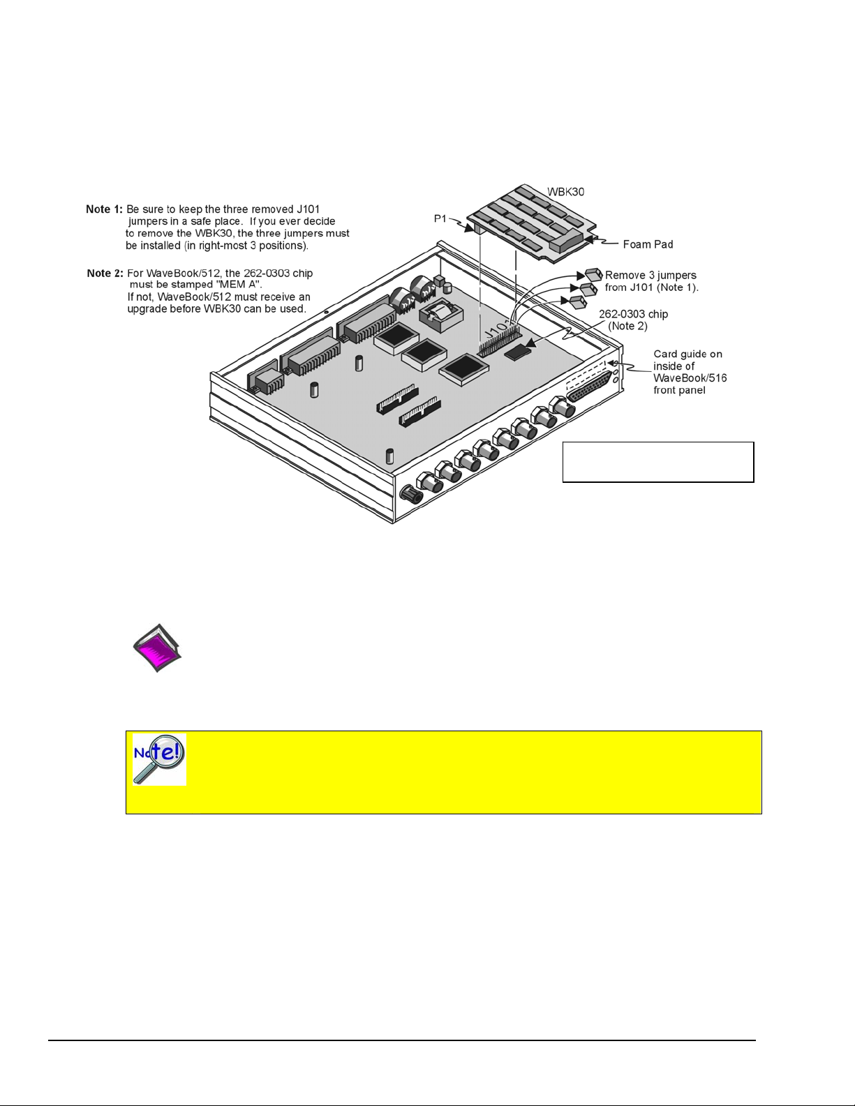
This illustration does not apply
to WaveBook/516E.
WBK30 Location
Reference Note:
Refer to the WBK Option Cards and Modules User’s Manual (p/n 489-0902) for WBK30
installation details. A PDF version of the document is included on the data acquisition CD.
Important Notice to WaveBook/516E Users!
WBK option cards for WaveBook/516E are installed at the factory per customer order.
Users are not to remove or install cards for WaveBook/516E. If you desire to remove or add
a card to a WaveBook/516E, contact the factory or your service representative.
2-22 System Setup and Power Options 979194 WaveBook User’s Manual
Page 43

Adding WBK Modules
Option Modules
Several WBK option modules are currently available for use with WaveBook systems. This section is
concerned with how the modules are connected and powered.
Reference Note:
WBK module functions and specifications are discussed in the WBK Option Cards and
Modules User’s Manual, p/n 489-0902. A PDF version of the document is included on your
data acquisition CD.
WBK10A
8-Channel Analog Expansion Module
WBK14
8-Channel Dynamic Signal Conditioning Module
WBK15
8-Channel 5B Signal Conditioning Module
WBK16
8-Channel Strain-Gage Module
WBK17
8-Channel Counter-Input Module with Quadrature
Encoder Support. This module can only be used with
WaveBook/512A, /516, 516A, and /516E.
WBK18
8-Channel, Dynamic Signal Conditioning Module with
Transducer Electronic Data Sheet support (T.E.D.S).
WBK25
10/100BaseT Ethernet Interface Module, includes three
Expansion Ports that can attach to any model of
WaveBook, DaqBook, WBK40 Series option, or any
combination of these devices.
WBK40
14-Channel Thermocouple Input Module with Mini-T/C
Connectors.
WBK41
Multi-Function I/O Module with: 14 thermocouple
channels, 40 Digital I/O Lines, 4 Counter Inputs, 2 Timer
Outputs, and an option for 4 Analog Channel Outputs.
Modules Currently Available for WaveBook System Expansion
Examples of various setups follow shortly.
WaveBook User’s Manual 979194 System Setup and Power Options 2-23
Page 44

Power requirements can vary greatly from one WaveBook system to another, and will need to be calculated
on a system by system basis, before power is applied to the system. This chapter includes instructions for
calculating power requirements.
Before discussing how to calculate power, we will look at the use of connectors and the types of cables
used.
Connectors and Cables
To attach a module, connections must be made for power, expansion control, and expansion signals.
The relevant connectors [located on the WBK Modules] are as follows:
• POWER IN – DIN5, connects to a 10 to 30 VDC source. When in a power daisy-chain,
POWER IN connects to the previous WaveBook or WBK module’s POWER OUT.
• POWER OUT – DIN5, can be connected to the next module’s POWER IN, providing the
5 amp current limit will not be exceeded. It may be necessary to use a supplemental power
supply. Power requirements and discussed in the following pages.
• EXPANSION CONTROL OUT – HD15, connects to the next module’s EXPANSION
CONTROL IN.
• EXPANSION SIGNAL IN – BNC, connects to the next module’s EXPANSION SIGNAL OUT.
• Additional Connectors on WBK25 Ethernet Module Only:
- ETHERNET – Connects to a PC’s 10/100BaseT Ethernet port, or to a
10/100BaseT Ethernet network.
- EXPANSION PORT (1, 2, & 3) – DB25, provides a means of connecting up to
three WaveBook or WBK40 Series devices.
Prior to connecting your devices to power, calculate your system’s power requirements as
discussed in upcoming section of this chapter. Note that examples of system setups follow
shortly.
CE Compliance
If your WaveBook system needs to be CE Compliant refer to the Declaration of
Conformity for each system component. Also, refer to Chapter 6, CE Compliance
and Noise Considerations.
Associated Cables
CA-35-12 (1 foot), CA-35-2 (2 foot), and CA-35-6 (6 foot) DB25 Male to DB25 Female Parallel
Cables. These cables are used to connect the parallel port of one device to that of another. They
are typically used to connect a WaveBook’s “TO COMPUTER” port (PARALLEL PORT) to the
EPP connector of the host PC.
CA-115 Power Cables. CA-115 cables are 6 inches long and have two 5-pin male DIN
connectors. CA-115s are frequently used to link WaveBook’s POWER OUT connector to a WBK
expansion module’s POWER IN connector. CA-115 cables are also used to link an expansion
module’s POWER OUT connector to the next daisy-chained module’s POWER IN connector.
CA-115 cables and the device DIN5 connectors (see following figure) are limited to 5 amps
at 15 VDC.
+10 to +30 V 4
+10 to +30 V 1
Return
2
5 No connection
3 Return
Power is supplied to WaveBook modules via a DIN5
type connector located on the rear panel of the
device.
DIN 5 Power Pinout*
2-24 System Setup and Power Options 979194 WaveBook User’s Manual
*The DIN5 pinout [to the left] is based on an external
view of a WaveBook rear panel.
Page 45

Note: An optional CA-116 power cable is available. The CA-116 permits the system to be plugged into
a vehicle cigarette lighter, allowing use of the vehicle’s battery as a power supply for the
WaveBook device.
Calculate system amp load prior to creating a system daisy-chain. Although WaveBook
device connectors and CA-115 and CA-116 power cables have 5 amp limits, TR-40Us are
limited to 2.2 amps. Tables for determining amp load are provided in the following section,
Calculating the System Power Requirement.
CA-129 Expansion Control Cables. Control messages are carried by CA-129 expansion-control
cables with HD-15, plug and socket connectors. The first expansion unit’s control input is driven
from the main unit’s control output. Control inputs of additional WBK modules are driven from
the preceding unit’s control output.
CA-150 Expansion Signal Cables. Expansion signals are carried by a CA-150-1 male BNC to
male BNC coaxial cable. Each WBK module drives a common analog bus that carries the signals
to WaveBook’s Analog-to-Digital Converter (ADC). Each WBK module has EXPANSION
SIGNAL IN and EXPANSION SIGNAL OUT connectors for daisy-chaining multiple units.
CA-177 Strain Gage Cables. CA-177 is an optional set of eight strain-gage cables intended for
use with the eight channels of WBK16. Discussions of the CA-177 strain-gage cable and bridge
applications are contained in the WBK16 document module.
CA-217 Digital Expansion Cables. These 8-inch cables are used for connecting one or more
WBK17s to a WaveBook/512A, /516, /516A, or /516E. The CA-217 cable has a DB25M
connector for Digital Expansion Out and a HD26M connector for Digital Expansion In. (See the
following page, second figure).
CA-242 and CA-242-7 Ethernet Patch Cables. CA-242 is a 1.5 foot cable that can be used to
connect a WaveBook/516E to an Ethernet port on a PC or network. CA-242-7 is a 7-foot cable
that can be used for the same purpose.
CA-74-1 and CA-74-5 SYNC Cables. 1-foot and 5-foot cables [respectively] used to synchronize
up to four “A” and/or “E” Series devices. The total combined SYNC cable length is not to
exceed 15 feet (4.57 m).
WaveBook User’s Manual 979194 System Setup and Power Options 2-25
Page 46

The Daisy-Chain Concept
Reference Note:
For information regarding
calculating system power
requirements, refer to the
upcoming section entitled,
Connecting the System to
Power.
Reference Note:
Refer to Chapter 3 for
additional system
examples.
WaveBook/512A, WaveBook/512A,
CA-150 CA-217
-
Example of a WaveBook Daisy-Chain with three WBK17 Modules
Unit* Channel #
How Channel Numbers are Determined
The analog input channel numbers are determined by the order of connection among the
WaveBook and attached WBK modules.
• Channel 0 is the WaveBook’s 8-bit digital I/O port.
• Channels 1 through 8 are the WaveBook’s main channels.
• Channels 9 through 16 are located on the first expansion unit connected directly
to the WaveBook.
• Additional channel numbers are added consecutively (in groups of 8)
with each added WBK module (see table at right).
WaveBook 0 (dig I/O)
WaveBook 1-8
1st WBK 9-16
2nd WBK 17-24
3rd WBK 25-32
4th WBK 33-40
5th WBK 41-48
6th WBK 49-56
7th WBK 57-64
8th WBK 65-72
* WBK in the “Unit” column refers to a module such as a WBK10A, WBK14, WBK15, WBK16, WBK17, WBK18.
Note that as this document goes to print the channel numbering method has not been determined for the WBK40 and
WBK41 modules.
2-26 System Setup and Power Options 979194 WaveBook User’s Manual
Page 47

Scan Synchronization
Up to four “A” and/or “E” Series WaveBooks can be scan-synchronized and triggered from any other
WaveBook (A or E Series) that is connected via a SYNC cable. Note that the two SYNC connectors
[on each WaveBook] are identical. Either one, or both, can be used to connect to other WaveBooks.
Note that chapter 3 includes additional system examples that make use of scan-synchronization.
Up to four units can be synchronized. The total combined length of the SYNC
cables is not to exceed 15 feet (4.57 m).
To PC, WBK25, or WaveBook/516E
CA-129
CA-150
CA-115, 5 Amp Limit
Synchronizing two WaveBook Systems, each having two Expansion Modules
Reference Notes:
Chapter 3, System Examples includes various system setups that make use of the
synchronization feature.
The Triggers section of Chapter 4, WaveBook Operation Reference, contains a
subsection regarding synchronization.
WaveBook User’s Manual 979194 System Setup and Power Options 2-27
Page 48
Connecting the System to Power
Calculating the System Power Requirement
CAUTION
An incorrect use of power can damage equipment or degrade performance. Prior to
connecting your devices to power, calculate your system’s power requirements.
CAUTION
Do not daisy-chain the power connections of more than three WBK10A modules.
Daisy-chaining a power connection to a fourth module will exceed the power
connector’s 5 amp current limit.
It is important to supply your system with adequate, reliable power. For this reason, you need to know
your system’s power requirement. Computing power use is also important when using batteries to power
modules, as you will need to know a safe runtime before recharging is required.
The following statements relate to system power. They should be reviewed before
proceeding.
Higher voltages draw fewer Amps for the same power.
Remember: Watts = voltage x current (W = V*I).
The TR-40U power adapter provides power that is sufficient for the WaveBooks
and WaveBook modules. You do not need to make power requirement
calculations unless you intend daisy-chaining units, or you have a critical battery
runtime.
Do not overload your power supplies. TR-40U power adapters are limited to
2.2 amps. However, you can use more than one TR-40U, as indicated in one of
the upcoming daisy-chain examples.
Current drawn from other sources, such as car batteries, can be estimated from
the following WaveBook Product Current Requirements table.
Use the current requirements and worksheet tables to calculate your system’s total power requirement.
Take the appropriate amperage values from the first table to fill in the second table; then perform the
indicated multiplication and addition operations to calculate the amperage for all units in your system.
2-28 System Setup and Power Options 979194 WaveBook User’s Manual
Page 49

WaveBook Product Current Requirements (in Amps)
Products and
Product Combinations
WaveBook/516 (alone)
WaveBook/516A (alone)
WaveBook/512A (alone)
WaveBook/516E (alone)
WBK10A (alone)
WBK11A
WBK12A
WBK13A
WBK14 Note 5
WBK15 without 5B modules
WBK15 (typical) Note 1
WBK15 (max) Note 2
WBK16 (no excitation)
WBK16 (full excitation)
WBK16/SSH
WBK17 (alone)
WBK17 with 1 encoder Note 3
WBK17 with 2 encoders Note 3
WBK17 with 3 encoders Note 3
WBK17 with 4 encoders Note 3
WBK18
WBK25
WBK30
WBK40 (alone) & w/o DBK46
WBK40 (max) Note 4
WBK41 (alone) & w/o DBK46
WBK41 (max) Note 4
Note 1: Typical with 8 voltage modules.
Note 2: Maximum load with 8 strain-gage modules. You may need to consult power specifications for
individual 5B modules and for any excitation currents required.
Note 3: Assumes 0.500 W per encoder.
Note 4: Assumes 8 DBK84 modules attached to P1 and no DBK46 installed.
Note 5: Assumes no transducer current is supplied.
DBK30A
14 VDC
1.00 0.50 1.20 0.60 1.00
1.80 1.0 2.2 1.1 1.7
0.35 0.17 0.42 0.20 0.35
0.27 0.10 0.32 0.16 0.22
0.47 0.23 0.56 0.27 0.45
0.57 0.28 0.68 0.33 0.50
0.90 0.50 1.08 0.53 0.85
0.13 0.08 0.16 0.09 0.12
0.24 0.13 0.29 0.15 0.23
0.75 0.36 0.90 0.44 0.75
1.08 0.52 1.30 0.61 1.00
1.80 0.87 2.10 1.00 1.67
1.20 .60 1.44 0.70 1.20
0.52 0.31 0.62 0.36 0.52
0.56 0.33 0.67 0.38 0.56
0.61 0.35 0.73 0.41 0.61
0.65 0.38 0.78 0.44 0.65
0.70 0.40 0.84 0.47 0.70
1.40 0.75 1.60 0.80 1.30
0.71 0.40 0.83 0.42 0.67
0.01 0.005 0.01 0.006 0.01
0.50 0.30 0.58 0.29 0.46
1.64 0.90 1.92 0.96 1.53
0.50 0.30 0.58 0.29 0.46
1.64 0.90 1.92 0.96 1.53
DBK30A
28 VDC
DBK34A
12 VDC
DBK34A
24 VDC
TR-40U
15 VDC
WaveBook User’s Manual 979194 System Setup and Power Options 2-29
Page 50

Worksheet for Power Requirements
Product Qty
WaveBook/512A
WaveBook/516 /516A
WaveBook/516E
WBK10A
WBK11A
WBK12A
WBK13A
WBK14
WBK15
WBK16
WBK17
WBK18
WBK25
WBK30
WBK40
WBK41
Maximum
× =
× =
× =
× =
× =
× =
× =
× =
× =
× =
× =
× =
× =
× =
× =
×
Amps
=
Amps
Totals
It is important to supply your system with adequate, reliable power. For this reason, you need to know
your system’s power requirement. Knowing the power requirement is also important when using batteries
to power modules, as you should know a safe runtime, i.e., how long you can run the system before
recharging is required.
Input voltage to the WaveBooks and to the system modules (WBK10A, WBK14, WBK15, WBK16,
WBK17, WBK18, WBK25, WBK40, and WBK41) must be in the range of 10 to 30 VDC and can come
from an AC-to-DC adapter or from another source, such as a battery. System cards such as theWBK11A,
WBK12A, or WBK13A get power from their host WaveBook or the WBK10A expansion module.
Available AC-to-DC adapters include the TR-40U, which has an input of 90-264 VAC and an output
of 2.2 amps @ 15 VDC.
Battery options include the DBK30A, DBK34A, and other 10 to 30 VDC sources, such as car batteries.
The DBK30A provides 14 VDC and when fully-charged has a storage capacity of 3.4 A⋅hr; car batteries
have much higher capacities. The basic formula for battery life is:
Runtime (hr) = Battery capacity (A⋅hr) / Current load (A)
Battery life and performance depend on various factors including battery type, condition, charge
level, and ambient temperature. Be sure you consider these factors, especially when runtime is a
critical.
2-30 System Setup and Power Options 979194 WaveBook User’s Manual
Page 51

System Power, Examples
WaveBook/516 with a
WBK11A Option Card:
Draws 1.22 Amps
WaveBook System Drawing 2.02 Amps
Reference Note:
Although the preceding two examples make use of one or more TR-40U power adapters,
other power sources can be used. These options are discussed in the following section,
Power Supplies.
WaveBook User’s Manual 979194 System Setup and Power Options 2-31
Page 52

Power Supplies
The power supplies that can be used with WaveBook setups are listed in the following table.
WaveBook Product Power Supplies
Item Name/Description Capacity
TR-40U
DBK30A
DBK34A
Other
DBK30A - Rechargeable Battery Module
DBK30A contains two rechargeable nickel-cadmium batteries for use with WaveBook, expansion WBK
modules, and transducers. DBK30A shares the same base dimensions as other WaveBook products,
allowing for convenient stacking. Note that stacking can be easily accomplished with the included splice
plates.
AC Power Adapter (shipped with WaveBooks & WBK Modules) 90-264 VAC input;
Rechargeable Battery/Excitation Module (optional) 12-14 VDC, or 24-28 VDC
UPS (uninterruptible Power Supply)/Battery Module (optional) 12 VDC, or 24 VDC
10 to 30 VCD source, such as a vehicle battery via a CA-116 cable. Depends on source
DBK30A Front Panel
2.2 A @ 15 VDC
3.4 A-hr @ 14 VDC
5.0 A-hr @ 12 VDC
The power adapter (included) converts AC power to 24 VDC for charging DBK30A’s two battery packs.
Automatic charging circuits recharge the internal batteries quickly and safely. The charged battery runtime
depends on the current load and mode of operation.
An internal slide switch (SW2) determines the unit’s mode. The two modes are:
• 14 VDC Mode (default)
• 28 VDC Mode
You should check the power requirements of each component in your system, and then
verify that the power source can provide sufficient power to meet your runtime
requirements.
Fully charge DBK30A’s batteries before use.
2-32 System Setup and Power Options 979194 WaveBook User’s Manual
Page 53

14 VDC Mode (default)
This mode provides 14 VDC for 3.4 A-hr. The typical battery runtime is from 3 to 6 hours depending on
the load. Unless 28 VDC is required, the 14 VDC mode should be used in WaveBook and WBK
applications,
28 VDC Mode
The 28 VDC mode actually provides both 14 VDC and 28 VDC. Loop currents for two-wire, 4-20 mA
transmitters (1.7 A-hr) require 28 VDC. The battery run-time ranges from 1 to 6 hours, depending on
system configuration. In this mode, 14 VDC is used for unregulated bridge excitation (for bridgeconfigured sensors, such as load cells), and power to WBK expansion products.
Hardware Setup
Configuration
The only configuration option is the choice of modes (14 VDC, or 28 VDC). If you do not need 28 V,
leave SW2 in the default position.
Unless you need 28 V, leave the unit in the 14 VDC mode. Use of the 28 VDC mode results in
a lower runtime, as only one battery pack can be used for 14 VDC. When in the 14 VDC mode,
both packs are used in parallel, resulting in a longer runtime for the same application.
Unless you need 28 V, leave the unit in the 14 VDC mode. Use of the 28 VDC mode results
in a lower runtime, as only one battery pack can be used for 14 VDC. When in the 14 VDC
mode, both packs are used in parallel, resulting in a longer runtime for the same application.
If you are using a pre-owned DBK30A, or are unsure of the mode selected, use the
following steps to check SW2’s position. Note that new units are always shipped with SW2
selected to the 14 VDC mode.
WaveBook User’s Manual 979194 System Setup and Power Options 2-33
Page 54

Internal switch SW2 is located on the printed circuit board, near the front center of the unit. To change or
verify the mode:
1. Remove DBK30A’s cover by removing one screw and sliding the cover forward until it separates from
the module.
2. Look near the front center of the circuit board and locate slide switch SW2.
3. Check SW2’s selection. The silkscreen indicates the 14 and 28 VDC positions.
4. Change the selection, if required. If you do not need 28 V, SW2 should be in the default position
(14 VDC).
5. Replace the top cover, and secure with screw.
Power
Connection. The figure shows the pinout for the POWER OUT DIN5 connector.
The 28 V pin is only active in the 28 VDC mode; however, the 14 V pin is active
GND
+14 V
regardless of the mode selected.
+28 V
The CA-115 cable connects to DBK30A’s POWER OUT connector and
WaveBook’s POWER IN connector. The cable can be used to daisy-chain a
DIN5 Power Out
DBK30A unit to a WBK expansion module.
28 VDC Mode. The primary purpose of the 28 VDC mode is to provide power for external loop
transmitters. The hookup is simple, as shown below.
T/C
WaveBo ok
2-Wire
+
T/C XMTR
2-Wire
+
Flow XMTR
4-20 mA
4-20 mA
Connecting Loop Transmitters
250
250
COM
N
Ω
N
Ω
Another use of the 28 VDC mode is to provide excitation for bridge-type sensors, such as load cells (strain
gages) and other devices that may be attached to 5B modules inside a WBK15.
Excitation voltage from DBK30A is not regulated by the unit, and must therefore be
regulated externally. For most load cells, excitation voltage should be regulated to 10 V.
Charging.
To charge the DBK30A batteries:
1. Connect the adapter to DBK30A’s POWER IN connector.
2. Plug the adapter into the AC power receptacle.
Note that the charge cycle will begin automatically whenever AC power is applied after an
interruption. The charge cycle will automatically end when the batteries are fully charged.
2-34 System Setup and Power Options
Charging DBK30A’s Batteries
979194
WaveBook User’s Manual
Page 55

3. To manually initiate a charge cycle, press the START CHARGE momentary rocker-arm switch.
Note that subsequent charge cycles applied to a fully-charged DBK30A will have no ill effect.
The module will sense the fully-charged status and revert to the trickle-charge state within a few
minutes.
Three LEDs on the DBK30A provide status information on the charging process or the external load.
LED Indicators & Descriptions
POWER IN
BATTERY CHARGING
POWER OUT
Indicates the charger is connected to a source of AC power and to the battery module.
Steady Light - Indicates the battery is in the high-current (2 A) charge mode.
Flashing - One or two flashes at a time indicates the batteries are fully charged.
Indicates power is flowing out to an external device, such as a WaveBook product.
CAUTION
Periodically, fully discharge the DBK30A to inhibit “lazy chemistry” (memory) in the
nickel-cadmium cells. To manually discharge a battery pack, connect a WaveBook to
the pack and leave it powered-on until the indicator lights go out.
Use While Charging. Both operating modes are capable of powering the WaveBook products while being
charged; however, the charging current is reduced, and charging time is increased. If AC power is
interrupted, a new charge cycle will begin automatically when AC power returns.
CAUTION
Even with the AC adapter, the batteries will eventually discharge under a WaveBook
operating load. Charging DOES NOT BEGIN AUTOMATICALLY (except on powerup). You must manually initiate the next charge cycle. Do not expect a WaveBook
powered by a DBK30A to operate as an uninterruptible power supply.
Stacking Modules
Stacking can be accomplished with splice plates, as discussed earlier in the chapter.
DBK30A Battery Module - Specifications
Name/Function: Rechargeable Battery Module
Battery Type: Nickel-cadmium
Number of Battery Packs: 2
Battery Pack Configuration: 12 series-connected sub-C
cells
Output Voltage: 14.4 V or 28.8 V (depending on the
selected mode)
Output Fuses: 2 A
Battery Amp-Hours: 3.4 A-hr (1.7 A-hr/pack)
Charge Termination: Peak detection
Charge Time: 2 hours
Charging Voltage from Supplied AC Adapter: 22 to 26
VDC @ 2 A
AC Adapter Input: 95 to 265 VAC @ 47 to 63 Hz
Size: 221 mm × 285 mm × 35 mm
(11" × 8-1/2" × 1-3/8")
Weight: 2.4 kg (6 lb)
WaveBook User’s Manual 979194 System Setup and Power Options 2-35
Page 56

DBK34A Vehicle UPS/Battery Module
DBK34A is similar to DBK34 in appearance and operation; but there are differences.
Before proceeding with this section, verify that your device is a DBK34A. If your device
does not have the “A” suffix, use the preceding section regarding the DBK34 Vehicle UPS
Module instead of this section.
DBK34A Front Panel
The DBK34A can power a data acquisition system in portable or in-vehicle UPS applications (both 12 V
and 24 V systems). Power storage capacity is 5 A-hr @ 12 VDC or 2.5 A-hr @ 24 VDC.
For reliable data acquisition in a vehicle, the DBK34A provides clean and consistent operating power:
• Prior to engine/generator start
• During engine start-up (battery sag due to the high-current demand of starter motor and solenoid)
• After engine turn off.
• Before and after connection to the vehicle
The DBK34A contains two sealed-lead rechargeable batteries (Gel-Packs), associated charging circuits and
current indicators. Typically, these batteries can last more than 500 full cycles and up to 10 years standby
lifetime at room temperature. Recharging is fast, and extreme temperature performance is good. The
DBK34A can be used with the LogBook, DaqBook, WaveBook, and related DBKs and WBKs. The unit’s
rugged metal package has a compatible 8×11” footprint for convenient stacking with Velcro tabs and
optional splice plates and handles for carrying.
Main and auxiliary power input comes from 12 or 24 VDC via a terminal block on the unit’s front panel
(12 or 24 V modes are set by front-panel jumpers). Automatic, temperature-compensated charging circuits
recharge the internal batteries quickly and safely. For trouble-free operation, you must fully charge the
batteries before use. The charged battery runtime will depend on the load and mode of operation.
During use of the internal batteries, the Charging LED blinks and a beeper sounds when battery life is
almost exhausted. Within a few minutes, internal cutoff circuits disconnect the load from the batteries to
prevent the possibility of deep-cycle damage.
Note: Current protection is provided by four fuses. Two 7.5A fuses for the unit’s internal batteries,
one 7.5 A fuse for an auxiliary (external) battery, and a 15 A fuse for the power input.
You can use a CA-172 cable to connect a vehicle battery (via a cigarette lighter) to the
DBK34A terminal board. The cable is six feet long, contains a cigarette lighter adapter at one
end, and stripped leads (for terminal connection) at the other.
For trouble-free operation, fully charge the batteries before use. Charged
battery runtime depends on the load and on the mode of operation.
2-36 System Setup and Power Options 979194 WaveBook User’s Manual
Page 57

Hardware Setup
Configuration for 12 Volt (Default) or 24 Volt Operation
DBK34A Block Diagram
DBK34A’s Screw Terminal Board, TB1
DBK34A’s screw terminal numbers read from right to left (9,8,7…3,2,1) when viewed from the front
panel (see figure).
For 12 Volt Operation:
1. Remove jumper from terminals 8 and 7, if present.
2. Use a jumper to short terminals 9 and 8
3. Use a jumper to short terminals 7 and 6
For 24 Volt Operation:
1. Remove jumpers from terminals 9 and 8, if present
2. Remove jumpers from terminals 7 and 6, if present.
3. Use a jumper to short terminals 8 and 7.
Power
Power In (12 or 24 VDC only).
• Connect MAIN POWER INPUT (+) positive to Terminal 3 of TB1.
• Connect MAIN POWER INPUT (-) negative to Terminal 5 of TB1.
• TB1’s Terminal 4 is reserved for factory use and is not to be connected by the user.
• The use of an optional auxiliary battery will extend run-time. For use with DBK34A,
auxiliary batteries must be of lead-acid chemistry, in the 2 to 3 A-Hr range, and of the same
voltage as that set by the Voltage Select Jumpers. Auxiliary batteries charge and discharge in
the same manner as the internal batteries. If an auxiliary battery is to be used, connect AUX
BATT (+) positive to Terminal 1 (of TB1), and connect AUX BATT (-) negative to Terminal
2 (of TB1).
WaveBook User’s Manual 979194 System Setup and Power Options 2-37
Page 58

Power Out. The pinout at the right applies to the
two POWER OUT DIN5 connectors. The DBK34A
package includes a short connecting cable to
connect to the powered device. This cable connects
the POWER OUT connector on the DBK34A and
to the POWER IN connector on the WaveBook,
LogBook, DaqBook, or WBK/DBK module.
DIN5 Power Output Connector (2 per DBK34A)
Indicators. Three front-panel LED indicators provide power and charging status information.
LED Indicators & Descriptions
MAIN POWER
CHARGING
DISCHARGING
Lights when the DBK34A power input is connected to a source of at least 12.25 VDC
Lights when the internal batteries are being fast-charged at a rate of 0.1 amp/cell or greater.
Lights when internal batteries (or auxiliary batteries) are discharging at a rate of 0.25A or greater.
Runtime. Approximate runtime under various loads can be computed from the storage capacity
(5 A-hr in 12 V mode; 2.5 A-hr in 24 V mode) and the load (main unit and other DBKs).
The following Load Wattage vs. Hours graph is for a typical new battery that is fully charged.
Charging: In general, lead-acid batteries [and related Gel-Packs] require charging at 120% of drain energy
(e.g., the 5 A-hr DBK34A requires a charge equal to or greater than 6 A-hr). Charging times vary; but 4 to
5 hours at 14 V is typical for a completely discharged battery; after which, charging may continue
indefinitely.
Note that 16 to 18 VDC at the power input is required for optimal charging.
CAUTION
Voltage applied to a DBK34A must not exceed 30 VDC.
Environmental Concerns
CAUTION
DBK34A Gel-Pack batteries contain toxic materials (Pb and H2SO4). At the end of
the battery life cycle (typically after 5 to 10 years of use), the Gel-Packs must be
recycled or properly disposed of.
2-38 System Setup and Power Options 979194 WaveBook User’s Manual
Page 59

Fuse Replacement
DBK34A contains four MINI ATO fuses that can be replaced by the user. Note that you should always
check your unit for blown fuses prior to sending it back to the factory for repair. This could save you time
and money.
The following table indicates the probable reason that a particular fuse may have blown, and includes part
numbers and fuse rating.
Fuse Rating Probable Cause of Blowing Fuse Replacement Fuse
F1 7.5 A Auxiliary Battery overload. 7.5A MINI ATO, LITTLEFUSE# 297-07.5
F2 7.5 A Output overload. 7.5A MINI ATO, LITTLEFUSE# 297-07.5
F3 7.5 A Output overload. 7.5A MINI ATO, LITTLEFUSE# 297-07.5
F4 15 A Input overload. 15A MINI ATO, LITTLEFUSE# 297-015
DBK34A, Fuse Location Reference
To replace a fuse:
1. Disconnect the DBK34A from loads and from supply power.
2. Remove the DBK34A’s cover plate. This requires the removal of 4 screws
(2 per side).
3. Examine the fuses (F1 through F4) to see which, if any, have blown. Note that
you can usually see the blown element through the fuse’s transparent casing.
4. Replace the blown fuse with the appropriate replacement fuse (see preceding
table). Note that the fuse value is present on top of the fuse; also, the fuses are
color coded as an aid to identification.
5. Replace the DBK34A cover and secure with screws (removed in step 2).
DBK34A UPS / Battery Module - Specifications
Name/Function: Vehicle UPS Module
Battery Type: Sealed-lead rechargeable
Number of Battery Packs: 2
Battery Pack Configuration: 6 series-connected D cells
Output Voltage: 12 V or 24 V (depending on jumpers)
Output Fuses: 8 A on each internal battery (2)
Battery Capacity (Amp-Hours):
5 A-hr in 12 V mode (parallel)
2.5 A-hr in 24 V mode (series)
Operating Temperature: -20°F to 122°F (-29°C to 50°C)
Size: 8½ × 11 × 1¾ in. ( 216 × 279 × 44 mm)
Weight: 7.2 lb (3.27 kg)
WaveBook User’s Manual 979194 System Setup and Power Options 2-39
Page 60

2-40 System Setup and Power Options 979194 WaveBook User’s Manual
Page 61

System Examples 3
Introduction …… 3-1
Cable Review …… 3-2
Single WaveBook Systems, 4 Examples …… 3-3
Example 1: WaveBook/516E with two WBK10A Modules …… 3-3
Example 2: WaveBook/516E with a WBK17 and a WBK40 …… 3-4
Example 3: WaveBook/516A with a WBK25, WBK17, and a WBK10A …… 3-5
Example 4: WaveBook/516E with a WBK41 and 2 WBK10A Modules …… 3-6
Multiple WaveBook Systems, 2 Examples …… 3-7
Example 1: A WaveBook/516E with 3 WaveBook/516A Units …… 3-7
Example 2: Two WaveBook/516A Sub-Systems Connected via a WBK25 Module ….. 3-8
Introduction
This chapter provides examples of various single WaveBook and multiple WaveBook systems, and
includes a review of the cables that are used for making various system connections.
Prior to connecting your devices to power, calculate your system’s power requirements as
discussed in chapter 2.
CE Compliance
If your WaveBook system needs to be CE Compliant refer to the Declaration of Conformity
for each system component. Also, refer to Chapter 6, CE Compliance and Noise
Considerations.
WaveBook User’s Manual 897895 System Examples 3-1
Page 62
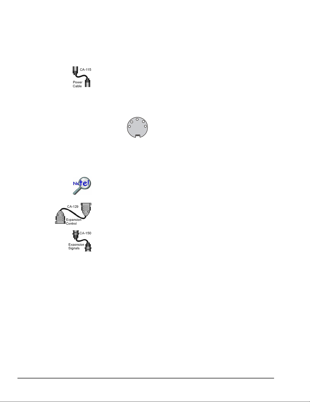
Cable Review
r
n
CA-35-12 (1 foot) and CA-35-2 (2 foot) DB25 Male to DB25 Female Parallel
Cables. Either of these two cables can be used to connect the parallel port of one
device to that of another. The cables are typically used to connect a WaveBook’s TO
COMPUTER (PARALLEL PORT) to the EPP connector of the host PC.
CA-115 Power Cables. CA-115 cables are 6 inches long and have two 5-pin male
DIN connectors. CA-115s are frequently used to link WaveBook’s POWER OUT
connector to a WBK expansion module’s POWER IN connector. CA-115 cables are
also used to link an expansion module’s POWER OUT connector to the next daisychained module’s POWER IN connector.
CA-115 cables and the device DIN5 connectors (see following figure) are limited
to 5 amps at 15 VDC.
Power is supplied to WaveBook modules via a DIN5
type connector located on the rear panel of the
device.
+10 to +30 V 4
+10 to +30 V 1
Return
2
5 No con
3 Retu
DIN 5 Power
Pinout*
*The DIN5 pinout [to the left] is based on an external
view of a WaveBook rear panel.
Note: An optional CA-116 power cable is available. The CA-116 permits the system to be
plugged into a vehicle cigarette lighter, allowing use of the vehicle’s battery as a
power supply for the WaveBook device.
Calculate system amp load prior to creating a system daisy-chain. Although
WaveBook device connectors and CA-115 and CA-116 power cables have 5 amp
limits, TR-40Us are limited to 2.2 amps. Tables for determining amp load are
provided in the Calculating the System Power Requirement section of Chapter 2.
CA-129 Expansion Control Cables. Control messages are carried by CA-129
expansion-control cables with HD-15, plug and socket connectors. The first expansion
unit’s control input is driven from the main unit’s control output. Control inputs of
additional WBK modules are driven from the preceding unit’s control output.
CA-150 Expansion Signal Cables. Expansion signals are carried by a CA-150-1
male BNC to male BNC coaxial cable. Each WBK module drives a common parallel
analog bus that carries the signals to WaveBook’s Analog-to-Digital Converter
(ADC). Each WBK module has EXPANSION SIGNAL IN and EXPANSION
SIGNAL OUT connectors for daisy-chaining multiple units.
CA-177 Strain Gage Cables. CA-177 is an optional set of eight strain-gage cables
intended for use with the eight channels of WBK16. Discussions of the CA-177
strain-gage cable and bridge applications are contained in the WBK16 document
module.
3-2 System Examples
CA-217 Digital Expansion Cables. These 8-inch cables are used for connecting one
or more WBK17s to a WaveBook/512A, /516, /516A, or /516E. The CA-217 cable
has a DB25M connector for Digital Expansion Out and a HD26M connector for
Digital Expansion In.
CA-242 and CA-242-7 Ethernet Patch Cables. CA-242 is a 1.5 foot cable that can
be used to connect a WaveBook/516E to an Ethernet port on a PC or network. CA242-7 is a 7-foot cable that can be used for the same purpose.
CA-74-1 and CA-74-5 SYNC Cables. 1-foot and 5-foot cables, respectively, that are
used to synchronize multiple devices. WaveBook synchronization applies only to “A”
and “E” Series devices.
897895
WaveBook User’s Manual
Page 63

Single WaveBook Systems, 4 Examples
d
Example 1: WaveBook/516E System with two WBK10A Modules
Power
Ethernet
Power
Device Interface Side Channel Input Side
WaveBook/516E System
with 2 WBK10A Modules
Lines and Cables Used in Example 1, excluding channel input connections.
1. Power Supply - To the WaveBook/516E POWER IN DIN 5 connector, +10 VDC to +30 VDC,
typically from a TR-40U power adapter.
2. Power Supply - To the first WBK10A’s POWER IN DIN 5 connector, +10 VDC to +30 VDC,
typically from a TR-40U power adapter.
3. Power Supply – From the first WBK10A’s POWER OUT DIN 5 connector, +10 VDC to +30 VDC,
to the second WBK10A’s POWER IN DIN 5 connector via a CA-115 Power Cable.
WBK10A (2
WBK10A (1
WaveBook/516E
n
)
st
)
4. Ethernet – From the WaveBook/516E ETHERNET jack to a 10/100BaseT Ethernet Network or to
the ETHERNET jack on a PC. Applicable Ethernet patch cables (1.5-foot or 7-foot) are CA-242 and
CA-242-7, respectively.
5. Expansion Control – From WaveBook/516E EXPANSION CONTROL to the first WBK10A’s
EXPANSION CONTROL IN. Connection is via a 15-pin CA-129 cable.
6. Expansion Control – From the first WBK10A’s EXPANSION CONTROL OUT to the second
WBK10A’s EXPANSION CONTROL IN. Connection is via a 15-pin CA-129 cable.
7. Expansion Signal – From the second WBK10A’s EXPANSION SIGNAL OUT to the first
WBK10A’s EXPANSION SIGNAL IN. Connection is via a BNC coaxial CA-150 cable.
8. Expansion Signal – From the first WBK10A’s EXPANSION SIGNAL OUT to the
WaveBook/516E’s EXPANSION SIGNAL IN. Connection is via a BNC coaxial CA-150 cable.
WaveBook User’s Manual 897895 System Examples 3-3
Page 64

Power
Ethernet
Power
Example 2: WaveBook/516E System with a WBK17 and a WBK40
Device Interface Side Channel Input Side
WaveBook/516E System
with a WBK17 and a WBK40
Lines and Cables Used in Example, excluding channel input connections.
1. Power Supply - To the WaveBook/516E POWER IN DIN 5 connector, +10 VDC to +30 VDC,
typically from a TR-40U power adapter.
2. Power Supply - To the WBK17’s POWER IN DIN 5 connector, +10 VDC to +30 VDC, typically
from a TR-40U power adapter.
WBK40
WBK17
WaveBook/516E
3. Power Supply – From the WBK17’s POWER OUT DIN 5 connector, +10 VDC to +30 VDC, to the
WBK40’s POWER IN DIN 5 connector via a CA-115 Power Cable.
4. Ethernet – From the WaveBook/516E ETHERNET jack to a 10/100BaseT Ethernet Network or to
the ETHERNET jack on a PC. Applicable Ethernet patch cables (1.5-foot or 7-foot) are CA-242 and
CA-242-7, respectively.
5. Synchronization – From a WaveBook/516E SYNC jack to a WBK40 SYNC jack. The connection
is made via a CA-74-1 cable.
6. Expansion – From WaveBook/516E EXPANSION PORT 1 to the WBK40’s PARALLEL PORT
connector. The connection is made via a 25-pin CA-35-12 cable.
7. Expansion Control – From WaveBook/516E EXPANSION CONTROL to the WBK17’s
EXPANSION CONTROL IN. Connection is via a 15-pin CA-129 cable.
8. Expansion Signal – From the WBK17’s EXPANSION SIGNAL OUT to the WaveBook/516E’s
EXPANSION SIGNAL IN. Connection is via a BNC coaxial CA-150 cable.
9. Digital Expansion – This connection is made on the channel input side of the units. The cable runs
from the WaveBook/516E’s DIGITAL I/O / EXTERNAL CLOCK / TTL TRIGGER connector to
the WBK17’s IN-DIGITAL EXPANSION connector (HD26 type). The connection is made via a
CA-217 Digital Expansion Cable.
3-4 System Examples 897895 WaveBook User’s Manual
Page 65

Power
Power
Example 3: WaveBook/516A System with a WBK25, WBK17, and a WBK10A
WBK10A
WBK17
WaveBook/516A
WBK25
Ethernet
Device Interface Side Channel Input Side
WaveBook/516A System
with a WBK25, WBK17, and a WBK10A
Lines and Cables Used in Example 3, excluding channel input connections.
1. Power Supply - To the WaveBook/516A POWER IN DIN 5 connector, +10 VDC to +30 VDC,
typically from a TR-40U power adapter.
2. Power Supply – From the WaveBook/516A’s POWER OUT DIN 5 connector to the WBK25’s
POWER IN DIN 5 connector via a CA-115 Power Cable.
3. Power Supply - To the WBK17’s POWER IN DIN 5 connector, +10 VDC to +30 VDC, typically
from a TR-40U power adapter.
4. Power Supply – From the WBK17’s POWER OUT DIN 5 connector, +10 VDC to +30 VDC, to the
WBK10A’s POWER IN DIN 5 connector via a CA-115 Power Cable.
5. Ethernet – From the WBK25’s ETHERNET jack to a 10/100BaseT Ethernet Network or to the
ETHERNET jack on a PC. Applicable Ethernet patch cables (1.5-foot or 7-foot) are CA-242 and
CA-242-7, respectively.
6. Expansion – From the WBK25’s EXPANSION PORT 1 to the WaveBook/516A’s PARALLEL
PORT connector. The connection is made via a 25-pin CA-35-12 cable.
7. Expansion Control – From WaveBook/516A’s EXPANSION CONTROL to the WBK17’s
EXPANSION CONTROL IN. Connection is via a 15-pin CA-129 cable.
8. Expansion Control – From the WBK17’s EXPANSION CONTROL OUT to the WBK10A’s
EXPANSION CONTROL IN. Connection is via a 15-pin CA-129 cable.
9. Expansion Signal – From the WBK10A’s EXPANSION SIGNAL OUT to the WBK17’s
EXPANSION SIGNAL IN. Connection is via a BNC coaxial CA-150 cable.
10. Expansion Signal – From the WBK17’s EXPANSION SIGNAL OUT to the WaveBook/516A’s
EXPANSION SIGNAL IN. Connection is via a BNC coaxial CA-150 cable.
11. Digital Expansion – This connection is made on the channel input side of the units. The cable runs
from the WaveBook/516A’s DIGITAL I/O / EXTERNAL CLOCK / TTL TRIGGER connector to
the WBK17’s IN-DIGITAL EXPANSION connector (HD26 type). The connection is made via a
CA-217 Digital Expansion Cable.
WaveBook User’s Manual 897895 System Examples 3-5
Page 66

Example 4: WaveBook/516E with a WBK41 and 2 WBK10A Modules
Power
Ethernet
Power
Power
WBK41
WaveBook/516E
WBK10A (1
WBK10A (2
st
)
nd
)
Device Interface Side Channel Input Side
WaveBook/516E with a WBK41 and 2 WBK10A Modules
Lines and Cables Used in Example 4, excluding channel input connections.
1. Power Supply - To the WaveBook/516E POWER IN DIN 5 connector, +10 VDC to +30 VDC,
typically from a TR-40U power adapter.
2. Power Supply - To the WBK41 POWER IN DIN 5 connector, +10 VDC to +30 VDC, typically
from a TR-40U power adapter.
3. Power Supply – To the first WBK10A POWER IN DIN 5 connector, +10 VDC to +30 VDC,
typically from a TR-40U power adapter.
4. Power Supply – From the first WBK10A’s POWER OUT DIN 5 connector, +10 VDC to +30 VDC,
to the second WBK10A’s POWER IN DIN 5 connector via a CA-115 Power Cable.
5. Ethernet – From the WaveBook/516E’s ETHERNET jack to a 10/100BaseT Ethernet Network or to
the ETHERNET jack on a PC. Applicable Ethernet patch cables (1.5-foot or 7-foot) are CA-242 and
CA-242-7, respectively.
6. Synchronization – From a WaveBook/516E SYNC jack to a WBK41 SYNC jack. The connection is
made via a CA-74-1 cable.
7. Expansion – From WaveBook/516E’s EXPANSION PORT 1 to the WBK41’s PARALLEL PORT.
The connection is made via a CA-35-12 cable.
8. Expansion Control – From WaveBook/516E’s EXPANSION CONTROL to the first WBK10A’s
EXPANSION CONTROL IN. Connection is via a 15-pin CA-129 cable.
9. Expansion Control – From the first WBK10A’s EXPANSION CONTROL OUT to the second
WBK10A’s EXPANSION CONTROL IN. Connection is via a 15-pin CA-129 cable.
10. Expansion Signal – From the second WBK10A’s EXPANSION SIGNAL OUT to the first
WBK10A’s EXPANSION SIGNAL IN. Connection is via a BNC coaxial CA-150 cable.
11. Expansion Signal – From the first WBK10A’s EXPANSION SIGNAL OUT to the
WaveBook/516E’s EXPANSION SIGNAL IN. Connection is via a BNC coaxial CA-150 cable.
3-6 System Examples 897895 WaveBook User’s Manual
Page 67

Multiple WaveBook Systems, 2 Examples
Example 1: A WaveBook/516E with 3 WaveBook/516A Units
Power
Power
Power
Ethernet
Power
Device Interface Side Channel Input Side
A WaveBook/516E with 3 WaveBook/516A Units
WaveBook/516A
rd
)
(3
WaveBook/516A
nd
)
(2
WaveBook/516A
st
)
(1
WaveBook/516E
Lines and Cables Used in Example 5, excluding channel input connections.
1. Power Supply - To the WaveBook/516E POWER IN DIN 5 connector, +10 VDC to +30 VDC,
typically from a TR-40U power adapter.
2. Power Supply – To each WaveBook/516A’s POWER IN DIN 5 connector, +10 VDC to +30 VDC.
Each unit uses its own dedicated TR-40U power adapter.
3. Ethernet – From the WaveBook/516E’s ETHERNET jack to a 10/100BaseT Ethernet Network or to
the ETHERNET jack on a PC. Applicable Ethernet patch cables (1.5-foot or 7-foot) are CA-242 and
CA-242-7, respectively.
4. Synchronization – From a WaveBook/516E SYNC jack to a SYNC jack on the first
WaveBook/516A. The connection is made via a CA-74-1 cable.
5. Synchronization – From the first WaveBook/516A’s remaining SYNC jack to a SYNC jack on the
second WaveBook/516A. The connection is made via a CA-74-1 cable.
6. Syncronization – From the second WaveBook/516A’s remaining SYNC jack to a SYNC jack on the
third WaveBook/516A. The connection is made via a CA-74-1 cable.
7. Expansion 1 – From the WaveBook/516E’s EXPANSION PORT 1 to the first WaveBook/516A’s
PARALLEL PORT connector. The connection is made via a 25-pin CA-35-12 cable.
8. Expansion 2 – From the WaveBook/516E’s EXPANSION PORT 2 to the second
WaveBook/516A’s PARALLEL PORT connector. The connection is made via a 25-pin CA-35-12
cable.
9. Expansion 3 – From the WaveBook/516E’s EXPANSION PORT 3 to the third WaveBook/516A’s
PARALLEL PORT connector. The connection is made via a 25-pin CA-35-12 cable.
WaveBook User’s Manual 897895 System Examples 3-7
Page 68

Example 2: Two WaveBook/516A Sub-Systems Connected via a WBK25 Ethernet Interface Module
This system example consists of two WaveBook/516A Systems, one located beneath a WBK25 Ethernet Module
and the other system above it. For this reason there are two lists of lines and cables used, i.e., a list for each subsystem.
WBK10A
st
)
(1
WBK17
Power
Power
Ethernet
Power
Power
Power
Device Interface Side Channel Input Side
WaveBook/516A
st
)
(1
WBK25
WaveBook/516A
nd
)
(2
WBK18
WBK10A
nd
)
(2
Two WaveBook/516A Sub-Systems Connected via a WBK25 Ethernet Interface Module
Lines and Cables Used in Example 2, excluding channel input connections.
1st WaveBook/516A Sub-System -- Includes the WBK25 Ethernet Module and the 3 components above it.
1. Power Supply - To the first WaveBook/516A’s POWER IN DIN 5 connector, +10 VDC to
+30 VDC, typically from a TR-40U power adapter.
2. Power Supply – To the WBK17’s POWER IN DIN 5 connector, +10 VDC to +30 VDC, typically
from a TR-40U power adapter.
3. Power Supply – From the WBK17’s POWER OUT DIN 5 connector to the first WBK10A’s
POWER IN DIN 5 connector via a CA-115 power cable.
4. Expansion Control – From the first WaveBook/516A’s EXPANSION CONTROL to the
WBK17’s EXPANSION CONTROL IN. Connection is via a 15-pin CA-129 cable.
5. Expansion Control – From the WBK17’s EXPANSION CONTROL OUT to the first WBK10A’s
EXPANSION CONTROL IN. Connection is via a 15-pin CA-129 cable.
6. Expansion Signal – From the first WBK10A’s EXPANSION SIGNAL OUT to the WBK17’s
EXPANSION SIGNAL IN. Connection is via a BNC coaxial CA-150 cable.
7. Expansion Signal – From the WBK17’s EXPANSION SIGNAL OUT to the first
WaveBook/516A’s EXPANSION SIGNAL IN. Connection is via a BNC coaxial CA-150 cable.
8. Expansion – From the first WaveBook/516A’s PARALLEL PORT to the WBK25 Ethernet
Interface Module’s EXPANSION PORT 1. The connection is made via a 25-pin CA-35-12 cable.
9. Synchronization – From the first WaveBook/516A’s SYNC jack to a SYNC jack on the second
WaveBook/516A. The connection is made via a CA-74-1 cable.
10. Ethernet – From the WBK25’s ETHERNET jack to a 10/100BaseT Ethernet Network or to the
ETHERNET jack on a PC. Applicable Ethernet patch cables (1.5-foot or 7-foot) are CA-242 and
CA-242-7, respectively.
11. Digital Expansion – This connection is made on the channel input side of the units. The cable
runs from the first WaveBook/516A’s DIGITAL I/O / EXTERNAL CLOCK / TTL TRIGGER
connector to the WBK17’s IN-DIGITAL EXPANSION connector (HD26 type). The connection is
made via a
CA-217 Digital Expansion Cable.
3-8 System Examples 897895 WaveBook User’s Manual
Page 69

Example 2 (continued):
2nd WaveBook/516A Sub-System -- Includes the WBK25 Ethernet Module and the 3 components beneath it.
1. Power Supply - To the second WaveBook/516A’s POWER IN DIN 5 connector, +10 VDC to
+30 VDC, typically from a TR-40U power adapter.
2. Power Supply – From the second WaveBook/516A’s POWER OUT DIN 5 connector to the
WBK25’s POWER IN DIN 5 connector via a CA-115 power cable.
3. Power Supply – To the WBK18’s POWER IN DIN 5 connector, +10 VDC to +30 VDC,
typically from a TR-40U power adapter.
4. Power Supply – To the second WBK10A’s POWER IN DIN 5 connector, +10 VDC to +30
VDC, typically from a TR-40U power adapter.
5. Expansion – From the second WaveBook/516A’s PARALLEL PORT to the WBK25 Ethernet
Interface Module’s EXPANSION PORT 2. The connection is made via a 25-pin CA-35-12 cable.
6. Expansion Control – From the second WaveBook/516A’s EXPANSION CONTROL to the
WBK18’s EXPANSION CONTROL IN. Connection is via a 15-pin CA-129 cable.
7. Expansion Control – From the WBK18’s EXPANSION CONTROL OUT to the second
WBK10A’s EXPANSION CONTROL IN. Connection is via a 15-pin CA-129 cable.
8. Expansion Signal – From the second WBK10A’s EXPANSION SIGNAL OUT to the WBK18’s
EXPANSION SIGNAL IN. Connection is via a BNC coaxial CA-150 cable.
9. Expansion Signal – From the WBK18’s EXPANSION SIGNAL OUT to the second
WaveBook/516A’s EXPANSION SIGNAL IN. Connection is via a BNC coaxial CA-150 cable.
Note: Ethernet and Synchronization aspects for Multiple WaveBooks, example 2, are dealt with in the list
of lines and connections for the first WaveBook/516A Sub-System.
WaveBook User’s Manual 897895 System Examples 3-9
Page 70

3-10 System Examples 897895 WaveBook User’s Manual
Page 71

WaveBook Operation Reference 4
Basic Operation …… 4-2
WBK Option Cards and Modules …… 4-7
Analog-Signal & Ground Connections…… 4-12
Digital I/O Connections…… 4-13
Triggers …… 4-15
Digital Trigger and Single-Channel Trigger ……4-15
Multi-Channel Trigger …… 4-16
Trigger Latency and Jitter …… 4-19
Pulse Trigger …… 4-20
Digital-Pattern Trigger …… 4-21
External Clock and Counter-Timer …… 4-21
Synchronizing Multiple WaveBooks …… 4-23
Programmable Features …… 4-25
Selecting a Channel’s Range …… 4-25
Selecting a Channels Units …… 4-26
mx + b, an Example …… 4-26
Reference Note:
Refer to the WBK Option Cards and Modules User’s Manual (p/n 489-0902) for detailed information regarding
the following WBK options. A PDF version of the document is included on the data acquisition CD.
WBK20A PCMCIA/EPP Interface Card – provides a Parallel Port Interface Card
WBK21 ISA/EPP Interface Plug-In Board – provides a Parallel Port Interface Plug-In Board
WBK23 PCI/EPP Interface Plug-In Board – provides a Parallel Port Interface Plug-In Board
WBK25 10/100BaseT Interface Module (includes 3 Expansion Ports) Interface/Expansion Module
WBK30 Memory Expansion Cards; 16 MB, 64 MB, or 128 MB
WBK40 14-Channel Thermocouple Input Module Expansion Module
WBK41 Multi-Function I/O Module (14-Channel T/C, 40-Channel Digital I/O,
WBK61 1000V High Voltage Adapter with Probe High Voltage Adapter
WBK62 100V High Voltage Adapter with Probe High Voltage Adapter
WBK Description Hardware Type
WBK10A 8-Channel Expansion Chassis Expansion Module
WBK11A 8-Channel SSH Card Signal Conditioning Card
WBK12A 8-Channel Programmable Low-Pass Filter Card Signal Conditioning Card
WBK13A 8-Channel Programmable Low-Pass Filter Card with SSH Signal Conditioning Card
WBK14 8-Channel Dynamic Signal Input Module (piezoelectric) Expansion Module
WBK15 8-Channel Isolated (5B) Signal Conditioning Module Expansion Module
WBK16 8-Channel Strain Gage Module Expansion Module
WBK17 8-Channel Counter-Input Module with Quadrature Encoder Support Expansion Module
WBK18 8-Channel Dynamic Signal Conditioning Module with Transducer
Electronic Data Sheet support (T.E.D.S.)
(WBK30/16, WBK30/64, WBK30/128)
4 Counter Inputs, 2 Timer Outputs, Optional 4 Analog Output
Channels)
Expansion Module
Memory Expansion Cards
Expansion Module
WaveBook Fan
The internal components of WaveBook/512A, /516, /516A, and /516E are air-cooled. Cooling
to ambient occurs as long as the surrounding environment is cooler than the unit. When the
unit becomes too warm for ambient cooling, a temperature sensor signals the fan to run.
Fan speed varies according to the WaveBook’s internal temperature. In cooler temperatures
the fan operates at lower speeds, thus reducing audible noise.
To allow for sufficient cooling, it is important to keep the fan and vents free of obstruction.
Note: The partial blocking of vents by fastener panels, when the units are stacked, does not
jeopardize unit cooling.
WaveBook/512A, /516, /516A , /516E 897895 WaveBook Operation Reference 4-1
Page 72

Basic Operation
WaveBook/512A, /516, /516A Block Diagram
Note 1: Each channel has input protection and connects to J10 via its own BNC connector. Channel 1 is the only
Note 2: An optional WBK11A, WBK12A, or a WBK13A card can be used in place of the PGA board. However,
channel that connects to the Pulse Discriminator and Analog Trigger.
these options are only to be installed [or removed] at the factory, as they are not “Plug-and-play” for
WaveBook/512A, WaveBook/516, and WaveBook/516A.
4-2 WaveBook Operation Reference 897895 WaveBook/512A, /516, /516A, /516E
Page 73

Note 3
WaveBook/516E Block Diagram
Note 1: Each channel has input protection and connects to J10 via its own BNC connector. Channel 1 is the only
Note 2: An optional WBK11A, WBK12A, or WBK13A card can be used in place of the PGA board. However, these
Note 3: Expansion Ports 1, 2, and 3 are typically used to connect up to three of the following devices:
WaveBook/512A, /516, /516A , /516E 897895 WaveBook Operation Reference 4-3
channel that connects to the Pulse Discriminator and Analog Trigger.
boards are only to be installed at the factory as they are not “Plug-and-play” for WaveBook/516E.
WaveBook/512A, WaveBook/516A, WBK40, WBK41. Any combination of these devices can be connected.
Page 74

Buffering, Amplifying, and Filtering Differential Signals
WaveBooks have 8 pairs of differential signals, one pair per BNC connector. Each pair of signals is
buffered and applied to a differential amplifier. The output of each differential amplifier can be applied to
a 5 pole, low pass filter. The filter and channel-selection multiplexer then switches the non-filtered and
filtered signals to a programmable gain amplifier (PGA). The amplified signal is level-shifted to locate the
desired range (within the A/D converter's fixed input range). Two offset settings are available, unipolar
and bipolar. Unipolar offset is used for sampling signals that are always positive. Bipolar offset is used
for signals that may be positive or negative. For example, when set for unipolar at a gain of ×5, the input
span is 2 volts and the amplified signal is offset so that input voltages from 0 to +2 volts can be digitized.
When set for bipolar operation, the offset is adjusted so that input voltages from -1.0 to +1.0 volts can be
digitized.
Digitizing Signals via the A/D Converter
For the WaveBook/516, /516A, and /516E, the signal is switched over to the A/D converter and digitized
to 16 bits in 1 µs. For WaveBook/512A, the signal is digitized to 12-bits in 1 µs. The A/D converter's
input can be switched to the expansion signal input, allowing the device to read one of 64 possible
expansion channels supplied by up to eight expansion modules [WBK10A, WBK14, WBK15, WBK16,
WBK17, WBK18]. The digital signal processor (DSP) processes the digitized value and corrects the value
for gain and offset errors. The DSP places the corrected result into the FIFO data buffer that holds the
samples until the PC reads the data. If the sample is used for triggering, the DSP determines if a valid
trigger event has occurred.
Using a Sample for Triggering
Low-Latency Analog or TTL-level Triggering
WaveBook includes low-latency analog or TTL-level triggering. The low-latency analog trigger detector
examines the WaveBook input channel 1 to determine if a trigger has occurred. The selected low-latency
trigger is presented to the control and timing circuit that starts the acquisition after the trigger. The TTL
trigger is taken directly from the digital I/O port. A detailed discussion of triggering begins on page 4-15.
Sync Ports
The “A” and “E” Series WaveBooks each contain two SYNC ports. With respect to each other, the units
can be scan-synchronized and triggered by connecting one of the two WaveBook SYNC ports to a SYNC
port on a second “A” or “E” Series WaveBook or to a SYNC port of a WBK40 or WBK41 module.
Additional information on synchronization begins on page 4-23.
Control, Timing, and Signal Processing
The Control-and-Timing Circuit and the Digital Signal Processor (DSP)
The Control-and-Timing Circuit and the Digital Signal Processor (DSP) work together. At each sample
time, the DSP: (a) reads from the scan sequence table, and (b) accordingly programs the Control-andTiming Circuit for the next sample. The Control-and-Timing Circuit waits precisely until the start of the
next sample, then selects:
the input channel
PGA gain
level-shifter offset
A/D input source
The control-and-timing circuit conveys this information to any attached expansion units and precisely
controls the A/D conversion timing.
4-4 WaveBook Operation Reference 897895 WaveBook/512A, /516, /516A, /516E
Page 75

The EEPROM
The EEPROM holds the calibration information needed for real-time sample correction.
Reading from and Writing to the Digital I/O Port
The digital I/O port is read and written by the Digital Signal Processor to transfer bytes of digital data.
It may be used as a simple 8-bit input port or as a 32-address byte-wide I/O port.
The high-speed EPP/ECP interface circuit connects the WaveBook and any attached printer to the PC via
standard DB-25 connectors. When the WaveBook is active, the interface holds the printer in a stable state;
and when the WaveBook is inactive, the interface connects the PC to the printer.
WaveBooks and the Ethernet, General Information
The following information applies to:
WaveBook/516E, when connected to the Ethernet
WaveBook/516A, when interfaced to the Ethernet via a WBK25 module or
interfaced to the Ethernet via a WaveBook/516E.
WaveBook/512A, when interfaced to the Ethernet via a WBK25 module or
interfaced to the Ethernet via a WaveBook/516E. However, WaveBook/512A
is 12-bit instead of 16-bit.
WaveBook/516, when interfaced to the Ethernet via a WBK25 module or
interfaced to the Ethernet via a WaveBook/516E. However, WaveBook/516
has no synchronization feature.
WaveBooks can transfer acquired data to the PC via a 10/100BaseT Ethernet connection. The Ethernet
connection allows for a continuous stream of data to be collected and stored. The WaveBooks can be
expanded up to 72 channels using 8-channel WBK expansion options. The WaveBook/516E also has 3
built-in parallel expansion ports, permitting connection of up to three additional WaveBook/516A,
WaveBook/512A, WBK40, and/or WBK41 units.
Note: When a WaveBook/516, /516A, or 512A is interfaced to the Ethernet via a WBK25 module, three
parallel expansion ports are made available via the module.
Each of up to four WaveBooks, i.e., the base unit plus 3 units connected to its [or the WBK25’s] expansion
ports, can acquire data at 1 MHz, with all acquired data flowing through the Ethernet port and back to the
PC. A sync signal between all “A” and “E” WaveBook devices ensures that the multi-device system will
synchronously acquire data.
One WaveBook/516E can transfer data back to the PC via Ethernet at the full rate
of 1 MSample/sec. When multiple WaveBooks are attached to one Ethernet port,
either through a WaveBook/516E or through a WBK25, the Ethernet may not
support the full sample bandwidth. In this situation, the use of a WBK30 option
may be required. To obtain information regarding the latest improvements in
Ethernet-based transfer rates contact the factory.
In total, up to 288 channels of high-speed input can be measured via one Ethernet link. Beyond that,
additional channels are possible using an Ethernet expansion hub, allowing multiple WaveBook units to be
attached to one PC.
The optional WBK40 and WBK41 expansion modules can be connected to the parallel expansion ports of
the WaveBook/516E, or to the identical expansion ports of the WBK25. Since the WBK40 has its own
200-kHz A/D converter, it does not consume bandwidth from the WaveBook’s 1-MHz A/D. The SYNC
connection insures that both A/Ds measure synchronously.
WaveBook/512A, /516, /516A , /516E 897895 WaveBook Operation Reference 4-5
Page 76

There are two advantages of seamlessly supporting multiple WaveBooks in one system. First, is the ability
to expand beyond the 72 channel capacity of a single WaveBook. Second, if the per-channel sampling rate
of a single WaveBook system is inadequate, then additional WaveBooks can provide more bandwidth per
channel. For example, a 16 channel, single-WaveBook/516E system with one WBK option provides a
maximum bandwidth of 62.5 kHz/channel, i.e., 1M divided by 16. Instead, a sampling rate of
125 kHz/channel could have been achieved by using one WaveBook/516E connected to one slave
WaveBook/516A. This new “per-channel” sampling rate was calculated as follows:
1 MHz divided by 8 equals 125 kHz/channel.
The most common and highest-performance Ethernet connection for WaveBook/516E and for WBK25 is
achieved via a dedicated, point-to-point Ethernet link between the PC and the unit’s Ethernet port. Data
transfer rates in this configuration will accommodate continuous, 1 Mreading/s transfers from the
WaveBook to the PC.
With an enterprise-wide Ethernet network connection, any number of WaveBooks can be connected to the
network. Enterprise-wide Ethernet networks are typically shared amongst a large number of devices. In
such a scenario, the data transfer rates from the WaveBook are dependent on other network traffic at the
time of data transfer.
If you need to have continuous, 1 Mreading/s transfers from the WaveBook, you should
avoid connecting WaveBooks to an enterprise-wide Ethernet network. However, to
improve the data transfer performance of WaveBooks that are connected to such a
network, a WBK30 memory option should be installed. Contact the factory for
additional information.
Up to three WaveBook/516A or WaveBook/512A units can be attached to the three Expansion Ports of a
WaveBook/516E or WBK25. This application is useful when the channel requirements exceed the 72
channel capability of one WaveBook. It is also useful when the per-channel bandwidth exceeds that which
could be accomplished by a lone WaveBook, or if multiple time bases are required.
Note: In multiple WaveBook applications, the system can appear to the user as one large, synchronous
system. However, a system composed of many WaveBooks can be configured as several
independent systems, and with each system having its own triggering and sampling rates.
The parallel expansion ports on a WaveBook/516E can also be used to attach WBK40 thermocouple
modules and/or WBK41 Multi-Function modules. The units are detailed in the WBK Options User’s
Manual (p/n 489-0902). A PDF version of the document is included on the data acquisition CD. Note that
the SYNC signal on an “A” or “E” Series WaveBook can connect to a SYNC port theWBK40 or WBK41,
ensuring that both A/Ds will operate in synch.
A large WaveBook system can be configured with one Ethernet link to a PC, and could consist of, for
example either of the following two scenarios. In each case the WaveBook was expanded to its maximum
72 channel capacity, for a total system capacity of 288 high-speed channels.
288 Channel System, Example 1 216 Channel System, Example 2
WaveBook/516E (“Master” Unit) Connected to Ethernet
WaveBook/516A (Expansion Port 1, “Slave” Unit)*
WaveBook/516A (Expansion Port 2, “Slave” Unit)*
WaveBook/516A (Expansion Port 3, “Slave” Unit)*
*Expansion Ports are on the WaveBook/516E.
WBK25 Ethernet Interface Module Connected to Ethernet
WaveBook/516A (Expansion Port 1, “Master” Unit)**
WaveBook/516A (Expansion Port 2, “Slave” Unit)**
WaveBook/516A (Expansion Port 3, “Slave” Unit)**
**Expansion Ports are on the WBK25 Interface Module.
Any one of the 3 WaveBooks can be designated as the
Master Unit, and the other two as Slave Units.
Synchronizing Multiple WaveBooks
WaveBook software establishes one of the system’s WaveBooks as a “master” unit and
the others as “slaves” units. Master WaveBooks can run at the full 1-MHz aggregate
sampling rate. Slave WaveBooks must have 1 µs of unassigned sampling time in the scan
group. Note that some trigger modes are not supported in multi-WaveBook systems.
Additional information regarding synchronization is provided on page 4-23.
4-6 WaveBook Operation Reference 897895 WaveBook/512A, /516, /516A, /516E
Page 77
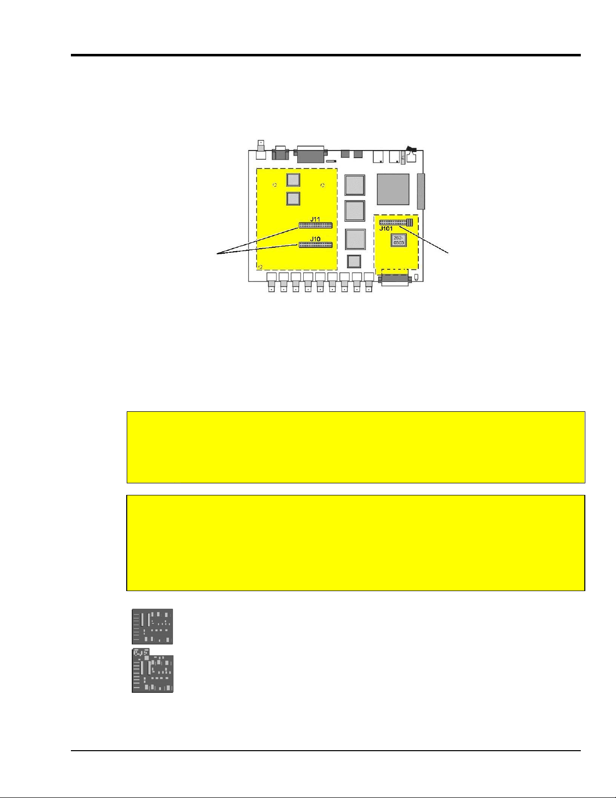
WBK Option Cards and Modules
WaveBook operation can be enhanced by the use of various WBK option cards and modules. A brief
synopsis of each option follows, while more detailed information is provided in the WBK Options User’s
Manual (p/n 489-0902). A PDF version of the document is located on the data acquisition CD. The
location of WBK card options [internal to WaveBook] are illustrated in the following figure. The board
layout includes header locations that the cards plug in to.
A Standard PGA Board, WBK11A,
WBK12A, or WBK13A option card
connects to J11 and J10 headers
on the WaveBook’s circuit board.
(See Notes 1 and 2)
You can use various modules and option cards to expand your WaveBook system. These WaveBook options
are known as WBKs. Internally, WaveBook has room for one signal-conditioning card. Externally, you can
use one or more expansion modules.
For WaveBook/516E, selected WBK card options must be installed at the factory. For other WaveBook
models, the WBK30 card option can be installed by the user; however, other option cards must be factoryinstalled.
Note 1:
Note 2:
The WBK30 memory
option connects to J101.
(See Notes 1 and 2)
Locations of WBK Option Card Connection Headers
WaveBook/516E Users
WBK option cards for WaveBook/516E are installed at the factory per customer order.
Users are not to remove or install cards for these products as the cards are not “plug-andplay” for these devices and erroneous signal values could result. If you desire to remove or
add a card to WaveBook/516E contact the factory or your service representative.
WaveBook/516, /516A, /512A, and WBK10A Users
With exception of the WBK30 option, WBK option cards for WaveBook/516, /516A, /512A,
and WBK10A are installed at the factory per customer order. Users are not to remove or
install cards for these products [other than WBK30 series cards] as the cards are not “plugand-play” for these devices and erroneous signal values could result. If you desire to remove
or add a card to these products (other than WBK30) contact the factory or your service
representative.
WBK11A
8-Channel Simultaneous Sample & Hold Card. Note that configurations are controlled by
software. There are no hardware settings.
WBK12A and WBK13A
WBK12A: Programmable Low-Pass Filter Cards (8 channels each)
WBK13A: Programmable Low-Pass Filter Card with SSH (8 channels each)
Note that configurations are controlled by software. There are no hardware settings.
WaveBook/512A, /516, /516A , /516E 897895 WaveBook Operation Reference 4-7
Page 78

WBK30
WBK30 is a DRAM-based memory board option that can be installed inside a WaveBook.
There are three models of WBK30 available; each significantly increases the capacity of a
WaveBook's standard data buffer of 64 K samples. Capacities are as follows:
WBK30/16 -16 MB, WBK30/64 - 64 MB, WBK30/128 - 128 MB
Note: For WaveBook/516E the WBK30 option, if selected, must be factory installed.
This illustration does not apply
to WaveBook/516E.
WBK30 Installation
Reference Note:
Refer to the WBK Options User’s Manual (p/n 489-0902) for WBK30 installation details. A PDF
version of the document is included on the data acquisition CD.
Important Notice! WaveBook/516E Users
WBK option cards for WaveBook/516E are installed at the factory per customer order.
Users are not to remove or install cards for these products as the cards are not “plug-andplay” for these devices and erroneous signal values could result. If you desire to remove or
add a card to WaveBook/516E contact the factory or your service representative.
Reference Note:
The WBK option cards and modules that follow are detailed later in the WBK Options User’s
Manual, p/n 489-0902. A PDF version of the document is included on the data acquisition CD.
4-8 WaveBook Operation Reference 897895 WaveBook/512A, /516, /516A, /516E
Page 79

Each of the following options are detailed in product-dedicated document modules. Note that the items represented in
the table are not necessarily shown to the same scale.
Each WBK10A module can be used to provide WaveBook with 8
additional differential-analog-inputs. The modules are equipped with
a programmable gain instrumentation amplifier (PGA) and, like the
WaveBook, each has a built-in expansion bus.
Up to eight WBK10A modules can be cascaded together for a system
capacity of 72 differential channels. Each module is capable of
supporting a WBK11A, WBK12A, or a WBK13A option card.
The WBK11A card can simultaneously sample 8 channels and can
be installed inside a WaveBook or in a WBK10A module. The cards
allow for concurrent (<150 ns) capture of multiple input channels and
virtually eliminate channel-to-channel time skewing.
Note: Use of this card requires factory installation.
The WBK12A and WBK13A are 8-channel programmable low-pass
filter cards for use with WaveBook data acquisition systems. These
cards install directly into a WaveBook or WBK10A module and
provide programmable low-pass filtering over all channels. Multiple
WBK12A and WBK13A cards can be installed in one system for up to
72 channels. All of the cards’ low-pass filters and cutoff frequencies
are configured via software.
WBK13A cards have the additional capability of sampling all
channels at the same time.
Note: Use of these cards requires factory installation.
The WBK14 is a dynamic analog signal input module. It enables
WaveBooks to interface with piezoelectric transducers that include
accelerometers, microphones, and force/pressure transducers.
Each WBK14 channel has a:
•
current source for transducer biasing
•
high-pass filter
•
programmable gain amplifier
•
anti-aliasing low-pass filter
•
simultaneous sample-and-hold (SSH) amplifiers
WBK10A
Analog Expansion Module
8 Channels via BNC Connectors
WBK11A
Simultaneous Sample & Hold Card (8 channels)
WBK12A
Programmable Low-Pass Filter Card
(8 channels)
WBK13A
Programmable Low-Pass Filter Card with SSH
(8 channels)
WBK14
Dynamic Signal Conditioning Module
8 Channels via BNC Connectors
The WBK15 module provides for a diverse range of signals available
through optional 5B modules. Measurement types include: LVDT,
potentiometer, isolated current loop, ±10mV to ±40V inputs, linearized
RTD, thermocouple, frequency-to-voltage, and strain gage.
See latest catalog or contact your sales representative in regard to the
types of 5B Modules available for your application.
WBK16 is an 8-channel strain-gage signal-conditioning module. Up to
eight WBK16 modules (64 channels) can be accommodated by the
WaveBook and scanned at 1 µs/channel. Almost all bridge
configurations are supported via a bridge-completion network and
software. High-gain differential-amplifier applications are also
supported. Software controls bridge configuration, gain, offset,
excitation voltage, polarity, filtering, and the calibration process.
The WBK17 is an 8-channel multi-function counter/encoder module.
Each of the high-speed, 32-bit counter channels can be configured for
counter, period, pulse width, time between edges, or encoder modes.
All channels are capable of measuring analog inputs that are digitized
by the WaveBook.
WBK15
8-Slot 5B Signal Conditioning Module
8 channels via 5B Modules
WBK16
Strain-Gage Module
8 channels via Standard Female DB9
WBK17
Counter-Input Module with
Quadrature Encoder Support
8 channels via Removable Screw Terminal Blocks
WaveBook/512A, /516, /516A , /516E 897895 WaveBook Operation Reference 4-9
Page 80

WBK18 provides 8 channels of dynamic signal input for WaveBook
systems. Each channel on the WBK18 has independent, software
WBK18
Dynamic Signal Conditioning Module with
Transducer Electronic Data Sheet support (T.E.D.S).
8 channels via BNC Connectors
WBK20A, WBK21, and WBK23 – Three Interface options that can be used to obtain an Enhanced Parallel Port.
WBK20A
PC-Card /EPP Interface
& Cable
WBK21
ISA/EPP Interface
Plug-in Board
WBK23
control for AC or DC coupling, ICP biasing (0 or 4 mA), and low-pass
filter cut-off frequency. The 8-pole Butterworth filter on each channel
is programmable from 5 Hz to 50 kHz, in a 1-2-5 progression. The
filter can also be bypassed, resulting in a bandwidth of greater than
200 kHz.
WBK20A – PCMCIA/EPP Interface Card and Cable
For linking WaveBook to a Notebook PC. This interface
provides an Enhanced Parallel Port via a PC-Card Slot.
WBK21 – ISA/EPP Interface Plug-in Board
For linking WaveBook to a desktop PC. This interface
provides an Enhanced Parallel Port via an ISA Bus-slot.
WBK23 – PCI/EPP Interface Plug-In Board
(For linking WaveBook to a desktop PC)
Provides an Enhanced Parallel Port from a PCI Bus-slot.
These three interfaces are shipped with separate documentation and
are not detailed in this manual.
PCI/EPP Interface Plug-In Board
WBK25
10/100BaseT Ethernet Interface Module
WBK30
WaveBook Memory Options
WBK40
Thermocouple Input Module
14 channels via Mini-T/C Connectors
The WBK25 provides high-speed Ethernet connectivity for
WaveBook, DaqBook and WBK40 series products. The WBK25
contains one 10/100BaseT Ethernet port for connection to a PC,
and three expansion ports that can attach to a WaveBook, DaqBook,
WBK40 Series option, or any combination of these devices.
WBK30 is a DRAM-based memory board that installs inside a
WaveBook. There are three models of WBK30 available; each
significantly increases the capacity of WaveBook's standard data
buffer of 64 K samples. Capacities are as follows:
WBK30/16 - 16 MB
WBK30/64 - 64 MB
WBK30/128 - 128 MB
Note: If a WBK30 option is selected for WaveBook/516E,
it must be installed at the factory.
The WBK40 attaches to any of the three parallel expansion ports on
the WaveBook/516E or the WBK25, and provides 14 thermocouple
input channels. The 14 built-in TC channels accept any type of
thermocouple, including types J, K, S, T, E, B, R, and N. Mini-TC
connections make it quick and easy to attach thermocouples. The
WBK40 can be expanded in 14 channel increments using the DBK84
TC expansion module. A total of 15 DBK84s can be attached to one
WBK40, for a total TC channel capacity of 224 channels.
4-10 WaveBook Operation Reference 897895 WaveBook/512A, /516, /516A, /516E
Page 81

WBK41
Multi-Function I/O Module
14 Thermocouple channels via Mini-T/C Connectors
40 Digital I/O Lines
4 Counter Inputs
2 Timer Outputs
(Optional) 4 Analog Channel Outputs
WBK61 and WBK62
WBK61: High-Voltage Adapter with 200:1 Voltage Divider
(1 channel)
WBK62: High-Voltage Adapter with 20:1 Voltage Divider
(1 channel)
The WBK4 attaches to the parallel expansion port on the
WaveBook/516E or WBK25 and provides 14 thermocouple inputs, 40
digital I/O lines, 4 counter inputs, and 2 timer outputs. The WBK41
can also be supplied with an internal, 4-channel, 16-bit,
100-kHz analog output option.
The built-in TC channels on the WBK41 are accessed via mini-TC
connectors on the front panel. The counter/timer functions and 16
bits of digital I/O are accessed via removable front panel screwterminal connectors. Additional digital I/O and expansion connectors
are located at the rear of the WBK41.
The WBK41 can be easily expanded beyond its built-in channel
capacity. A maximum WBK41 system can include up to 224 TC input
channels, 272 digital I/O channels, 4 analog output channels,
4 counter input channels and 2 timer output channels.
WBK61 and WBK62 are single-channel high-voltage adapters that
can be used with the WaveBook or WBK10A expansion modules.
In addition, WBK61 and WBK62 can be used in conjunction with
WBK11A, WBK12A, and WBK13A option cards.
WBK61 and WBK62 include safety-style banana-jacks for the high
and low inputs, and 60-inch (152 cm) cables with probe tips and
alligator clips for easy input connection.
WaveBook Fan
The internal components of WaveBook/512A, /516, /516A, and /516E are air-cooled. Cooling
to ambient occurs as long as the surrounding environment is cooler than the unit. When the
unit becomes too warm for ambient cooling, a temperature sensor signals the fan to run.
Fan speed varies according to the WaveBook’s internal temperature. In cooler temperatures
the fan operates at lower speeds, thus reducing audible noise.
To allow for sufficient cooling, it is important to keep the fan and vents free of obstruction.
Note: The partial blocking of vents by fastener panels, when the units are stacked, does not
jeopardize unit cooling.
WaveBook/512A, /516, /516A , /516E 897895 WaveBook Operation Reference 4-11
Page 82

Analog Signal & Ground Connections
Channel Analog Input, BNC Signal Connections
For each of the eight channel analog inputs, the BNC center (+) and shield (-) are internally connected to
WaveBook’s binding post labeled, ANALOG COMMON. The center (+) and shield (-) each connect to
ANALOG COMMON through a 5 MΩ resistor, resulting in a 10 MΩ differential input resistance
(see figures). WaveBook’s ANALOG COMMON connects to the computer power supply ground through
the TO COMPUTER DB25 connector and cable.
If the host computer is a desktop PC, then the computer ground will likely connect to the
AC power line ground.
If the host computer is a notebook PC, then the computer ground could be:
(a) floating, for example, when operating on batteries, or
(b) connected to a vehicle ground, for example, when using an automotive cigarette lighter adapter in
conjunction with the vehicle’s battery.
Note that a pair of Schottky diodes is used in the WBK10A to clamp the ANALOG COMMON to within
0.3V of computer ground (see figure).
WaveBook and WBK10A both have isolated power supplies. Power input common is isolated from
ANALOG COMMON by >10
9
Ω in parallel with 0.1µF.
For WaveBook/512A, /516, /516A, /516E, or WBK10A to correctly measure analog
signals, each signal must be within ±11 volts of ANALOG COMMON. The following
notes provide guidelines on how to achieve this.
Like WaveBooks, notebook computers are rarely connected to AC power line ground.
This is true even when these devices are plugged into AC adapters.
Floating Grounds: If the computer is battery operated and the signal source is floating (such as an
ungrounded sensor), then the internal 5 M
Ω resistors may provide enough of a return path to ANALOG
COMMON. If either the computer or the analog signal source is committed to AC power line ground, then
you will require a direct connection between the signal source and ANALOG COMMON.
When in doubt, connect the signal source common to ANALOG COMMON.
A single-ended signal source needs to have its common connected to ANALOG COMMON. When
connecting several signal source commons to ANALOG COMMON, it is important that there is no voltage
potential [between these signal source commons]. Otherwise, ground currents will circulate, leading to
measurement errors.
If there is a fixed voltage potential between multiple signal source commons, then only one of these signal
source commons needs connected to ANALOG COMMON. This is true as long as the common mode
voltage of any input does not exceed ±11 volts.
4-12 WaveBook Operation Reference 897895 WaveBook/512A, /516, /516A, /516E
Page 83

Digital I/O Connections
16-Bit Mode
For 16-bit mode, the following signals are present on the WaveBook’s DB25F high-speed digital I/O
connector. Note that 8-bit mode is covered in the following section.
16 High-Speed Digital I/O Lines (D0 through D15)
TTL Trigger Input (TTLTRG)
+15 V (pin 23), -15 V (pin 22), 50 mA max. (each)
two +5 V (pin 19 and pin 21), 250 mA max. (total)
External Clock Input (pin 20)
Digital Clock (pin 18), only used for WBK17 applications
two Digital Grounds (pins 24 and 25)
To sample just 16 digital input signals, connect them directly to the digital I/O data lines.
D15 is the most significant bit, and D0 is the least.
Digital I/O Connections, 16-Bit Mode
D0 through D15 High Speed Digital I/O data lines
TTLTRG TTL trigger input
External Clock
Input
+5 VDC 250 mA maximum
+15,-15 VDC 50 mA maximum (each)
Digital Clock Pin 18, only used for WBK17
Digital Grounds Pins 24 and25
16 bit mode, read/write strobe,
Pin 20
applications
DB25 Pinout, 16-Bit Mode
The following figure depicts the WaveBook’s Front Panel. The DB25 connector and cable for External
Clock and TTL External Trigger are represented.
WaveBook with Optional Clock and External Trigger Cable (CA-178)
WaveBook/512A, /516, /516A , /516E 897895 WaveBook Operation Reference 4-13
Page 84

8-Bit Mode
The following pinout can be used for a WaveBook/512A, /516, /516A, or /516E providing that the unit is in the 8-bit
mode, instead of in the 16-bit mode as discussed in the preceding section. When in 8-bit mode, the DB25 connections
are as follows:
8 Digital I/O Lines (D8 – D15)
5 Address Lines (A0 –A4)
Active-low Digital I/O Enable output (EN-)
Active-low Digital I/O Write Strobe (WR-)
Active-low Digital I/O Read Strobe (RD-)
TTL Trigger Input (TTLTRG)
+15 V (pin 23), -15 V (pin 22), 50 mA max. (each)
two +5 V power (pins 19 and 21), 250 mA max. (total)
two Digital Grounds (pins 24, and 25)
Digital Clock (pin 18), only used for WBK17 applications
External Clock Input (pin 20)
DB25 Pinout, 8-Bit Mode
D8 through D15 Digital I/O data lines
A0 through A4 Digital I/O address lines
EN- Active-low digital I/O enable
RD- Active-low read strobe
WR- Active-low write strobe
TTLTRG TTL trigger input
+5 VDC 250 mA maximum
+15,-15 VDC 50 mA maximum (each)
Digital Grounds Pins 24, and 25
DB25 Pinout for 8-Bit Mode
Digital Clock Pin 18, only used for WBK17
External Clock Input Pin 20
applications
To sample just 8 digital input signals, make connections directly to the digital I/O data lines. D15 is the
most significant bit, and D8 is the least. The address lines, the read and write strobes, and enable signal
can be left disconnected.
4-14 WaveBook Operation Reference 897895 WaveBook/512A, /516, /516A, /516E
Page 85

Triggers
External signals can be used to start or synchronize the data acquisition process.
The following trigger sources are supported:
Software Trigger. This trigger event is generated by a software command from the PC
without waiting for an external event. This feature may be used to begin a data acquisition
immediately or to force an acquisition to occur if the expected trigger did not occur.
Digital Trigger. Digital (or TTL-level) triggering (either rising- or falling-edge input) is
performed by digital logic connected to the digital expansion connector.
Single-Channel Trigger. Single-Channel (or Channel 1 Analog) triggering (rising or falling
signal level) is performed by comparator-based analog hardware connected directly to
analog input channel 1.
Multi-Channel Trigger. Here, the trigger event is a combination of measured channel
values. WaveBook's Digital Signal Processor (DSP) performs multi-channel triggering. The
DSP samples the specified channels; if programmable conditions are met, a trigger is
generated. Multi-channel triggering examines digitized data, and the trigger latencies are
much greater.
Digital-Pattern Trigger: This expanded digital-trigger capability allows data collection to
start when a user-defined 16-bit digital pattern is matched on the digital I/O connector.
This feature is useful when trying to capture noise, vibrations or some other physical
disturbance; such as those that can occur in a programmed logic controller’s digitally
sequenced process.
Pulse Trigger: The pulse trigger is a high-bandwidth input that enables triggering and the
correlation of lower-speed waveforms with the occurrence of a high-speed pulse. With
pulse trigger, the user defines pulse amplitude between ±5 V and pulse width from 100 ns to
800 ms.
More detailed information regarding triggers follows.
Digital Trigger & Single-Channel Trigger
The input of the digital (TTL) trigger and the output of the single-channel signal-comparator are each
connected directly to hardware circuits to provide low-latency triggering. WaveBook can respond to a
TTL or analog trigger with a jitter (or uncertainty in latency) of no more than 100 nanoseconds (ns).
If not collecting pre-trigger data, WaveBook responds to the trigger with a latency of less than
200 ns for TTL and 300 ns for analog.
If collecting pre-trigger data, then triggers are not acted upon until the end of the current pre-
trigger scan. This increases the trigger latency and jitter, but preserves the specified scan rates.
When using the single-channel trigger, the Channel 1 analog input signal is compared with a
programmable voltage level to generate an internal TTL signal that is true if the analog input is greater
than the programmable voltage level (false if less).
When the digital trigger is used, then the TTL trigger signal from the digital I/O connector is used directly.
The resulting TTL signal is examined under program control for either a false-to-true (rising edge) or trueto-false (falling edge) transition which, when it occurs, is the trigger event.
If the system is ready for a trigger, then the trigger event will be acted upon. If the system is not ready
(due to incomplete configuration or because it is still finishing the previous trigger's action), the trigger will
be ignored. No indication of an ignored trigger is given.
WaveBook/512A, /516, /516A , /516E 897895 WaveBook Operation Reference 4-15
Page 86

The low-latency analog trigger compares the analog signal with a programmable voltage source. The
N
A
r
r
A
M
effective range of this voltage source depends on whether or not the WBK11A SSH option is installed.
Without SSH, the trigger threshold is settable from -5.0 to +9.996 volts with 12-bit
(WaveBook/512A) resolution, regardless of any channel's gain settings. This gives better than 1%
resolution at even the smallest input ranges (such as 0-1 or ±0.5 volts).
With SSH, the single-channel (Channel 1 analog) signal is first amplified by the SSH
programmable gain amplifier before being compared with the programmable voltage. This allows
precise trigger-level adjustment, even at high gain.
Analog-Trigger Comparator, Ranges and Resolutions
For WaveBook/512A, /516, /516A, and /516E
SSH Input Range Trigger Threshold Range Resolution (mV)
0-10 or ±5 -5.0 to 9.996 0.299
0-5 or ±2.5 -2.5 to 4.998 0.114
0-2 or ±1 -1.0 to 1.999 0.0458
0-1 or ±0.5 -0.5 to 0.9996 0.0229
0-0.5 or ±0.25 -0.25 to 0.4998 0.0114
0-0.2 or ±0.1 -0.10 to 0.1999 0.00458
0-0.1 or ±0.05 -0.05 to 0.09996 0.00229
Hysteresis
The analog trigger circuit has hysteresis that reduces the occurrence of re-triggering due to input noise.
The hysteresis level without SSH is 25 mV; the hysteresis with SSH is 1/600 of the comparator range. The
next figure shows the hysteresis effect for a rising-edge trigger.
Trigger
Amplitude
o
Trigger
Time
Trigger
Hysteresis Effect on a Rising-Edge Trigger
Trigger Level
Hysteresis Range
A trigger will occur when the analog input rises above the trigger level—but only after the input level has
been below the hysteresis range. If the level momentarily drops just below the trigger level (perhaps due to
noise) and then rises above it again, no extra triggers will be generated—the signal did not drop below the
hysteresis range. After the level drops below hysteresis, it can then again produce a trigger by rising above
the trigger level.
Multi-Channel Trigger
When the small hardware-limited latencies of the digital (TTL) and single-channel (Channel 1 analog)
triggers are not required, the DSP chip may be used to examine the samples from one or more channels and
to decide if they constitute a pre-defined trigger condition.
The DSP can sample up to 72 input channels and
examine each one to determine if it meets programmed
levels for a valid trigger. This multi-channel triggering
is a two-step process:
1. The DSP examines each of its specified input
signals to determine trigger validity.
2. After all of the channels have been examined, the
nalog
Input
Signals
DSP logically combines the individual triggers to
generate the actual trigger. The DSP may be
programmed to generate a trigger if any individual
trigger is valid (OR) or if all triggers are valid
Re-Arm Command
From Control Circuits
(AND). See figure.
4-16 WaveBook Operation Reference 897895 WaveBook/512A, /516, /516A, /516E
Trigger
Detector
Trigger
Detector
Trigger
Detector
Invalid Trigger
Valid Trigge
Valid Trigge
Trigger
Logic
ND
(all)
OR
(any)
ulti-Channel Trigger Detection
No Trigger
Trigger
Page 87

Trigger validity in a multi-channel environment is determined by the logical relationship among three
Tri
Tri
elements (slope, duration, and initialization) as discussed in the next section.
Multi-Channel Trigger Types
The first step in multi-channel
triggering is to examine the input
signals. To determine trigger
validity, WaveBook can examine
each input signal in 1 of 8 ways.
Note: Each trigger type is a
combination of three
elements: slope, duration,
and initialization.
Trigger Type Slope Duration Initialization
Above-level
Below-level
Above-level-with-latch
Below-level-with-latch
Rising-edge
Falling-edge
Rising-edge-with-latch
Falling-edge-with-latch
Rising Instantaneous Level
Falling Instantaneous Level
Rising Latched Level
Falling Latched Level
Rising Instantaneous Edge
Falling Instantaneous Edge
Rising Latched Edge
Falling Latched Edge
Slope (above/rising or below/falling) sets whether the trigger is valid when the signal is:
Above the trigger level (rising)
Below the trigger level (falling).
Duration (instantaneous or latched) specifies the action to take if the signal level becomes invalid after it
has been valid:
Instantaneous triggers become invalid as soon as the signal does; they are used to trigger on
the coincidence of signals, when two or more signals are simultaneously valid.
Latched triggers remain valid until the acquisition is complete; they are used to trigger on the
occurrence of signals, when two or more signals have already become valid.
The trigger duration only makes a difference in multi-channel "AND" triggering. In multi-channel "OR"
triggering, WaveBook will be triggered as soon as any channel becomes valid; what happens when a
channel becomes invalid does not matter. In contrast, "AND" triggering waits for all of the triggers to be
valid; and so, latching can be important for rapidly changing signals.
Initialization (level or edge) specifies the sequence necessary for a signal to be a valid trigger:
Level triggers become valid as soon as they reach or exceed the trigger level, even if they are
already past the trigger level when the acquisition is started.
Edge triggers first wait until the signal level is invalid. Then they wait for the signal to reach
the trigger level before becoming valid. Thus, level triggers look for a signal level, whenever
it occurs; and edge triggers look for a rising or falling transition that reaches the trigger level.
Examination of the input signals compares two specified signal levels: (a) The trigger level determines
when the input channel is a valid trigger, and (b) the hysteresis is the amount by which the channel must
differ from the trigger level for the channel to become invalid.
Above-Level Trigger
Rising slope
Instantaneous duration
Level initialization
gger
No
Trigger
gger
Trigger Level
Hysteresis
This trigger is valid whenever the signal level is above the trigger level and stays valid until the signal level
goes below the hysteresis range. In the figure, the channel trigger is valid during the 2 shaded intervals.
Whether this condition triggers WaveBook or not, depends on the type of multi-channel triggering ("AND"
or "OR") and on the state of other trigger channels. With "OR" multi-channel triggering, WaveBook will
trigger when the signal first rises above the trigger level—if ready for a new trigger, WaveBook will also
trigger the second time the signal rises above the trigger level. With "AND" multi-level triggering,
WaveBook will not trigger until every specified trigger channel is valid. If all other trigger channels are
valid, WaveBook will trigger when the signal reaches the shaded region; but if some channels are not
valid, this channel will have no effect.
WaveBook/512A, /516, /516A , /516E 897895 WaveBook Operation Reference 4-17
Page 88

Below-Level Trigger
Falling slope
No Trigger
No Trigger
Instantaneous duration
Level initialization
Trigger Trigger
Hysteresis
Trigger Lev el
This trigger is valid whenever the signal level is below the trigger level and stays valid until the signal level
goes above the hysteresis range (the reverse of above-level triggering). As with all multi-channel trigger
types, WaveBook's actual trigger depends on the combination of this trigger with the other channels'
trigger states.
Above-Level-With-Latch Trigger
Rising slope
Latched duration
Level initialization
Trigger
Trigger Level
In this trigger type, the channel becomes valid when the signal level rises above the trigger level and stays
valid until the acquisition is complete and WaveBook is re-armed.
Below-Level-With-Latch Trigger
Falling slope
Latched duration
Level initialization
Trigger
Trig ger Level
The channel becomes valid when the signal level rises above the trigger level and stays valid until the
acquisition is complete and WaveBook is re-armed (the reverse of above-level-with-latch triggering).
Latched triggers are often used in multi-channel "AND" triggering, where WaveBook will not trigger until
all trigger channels are valid. After a latched trigger becomes valid, it stays valid (waiting for the other
triggers to become valid) until WaveBook is triggered and the acquisition completes. If the trigger is nonlatched instead of latched, the channel may not stay valid and WaveBook will not trigger until the channel
becomes valid again and all channels simultaneously reach their trigger levels. In other words, latched
triggering is used to trigger after something has occurred, but non-latched triggering is used only during
the simultaneous occurrence of desired signal levels. It is possible to combine different trigger types in a
single multi-channel trigger. For example, WaveBook could trigger when channel 3 is below 0.9 volts
after channel 2 has gone above -1.3 volts (by configuring channel 3 for below-level triggering and channel
2 for above-level-with-latch triggering).
Rising-Edge Trigger
Rising slope
Instantaneous duration
Edge initialization
This trigger becomes valid after the signal level has been below the hysteresis range and then goes above
the trigger level. This trigger becomes invalid when the signal level goes below the hysteresis range.
Unlike above-level triggering, the channel cannot become valid until the signal level first goes below the
hysteresis range. This prevents the false triggering that would occur if the signal were above the trigger
level at the start of the acquisition.
4-18 WaveBook Operation Reference
Trigger
Trigger Level
Hysteresis
No
Trigger
897895
WaveBook/512A, /516, /516A, /516E
Page 89

Falling-Edge Trigger
Falling slope
No Trigger
Instantaneous duration
Edge initialization
Trigger
Hysteresis
Trigger Level
This trigger is the reverse of the rising-edge trigger: the trigger becomes valid after the signal level has
been above the hysteresis range and then goes below the trigger level. This trigger becomes invalid
whenever the signal level goes above the hysteresis range. This prevents the false triggering that would
occur with below-level triggering if the signal was below the trigger level at the start of the acquisition.
Rising-Edge-With-Latch Trigger
Rising slope
Latched duration
Edge initialization
Trigger
Trigger Level
Hysteresis
This trigger becomes valid like a rising-edge trigger: when the signal level goes above the trigger level
after first being below the trigger range. However, the rising-edge-with-latch trigger does not become
invalid, regardless of the signal level, until the acquisition is complete. Rising-edge-with-latch is used to
trigger after the channel has reached the trigger level, rather than just while the channel is above the trigger
level.
Falling-Edge-With-Latch Trigger
Falling slope
Latched duration
Edge initialization
Trigger
Hysteresis
Trigger Level
This trigger is the reverse of the rising-edge-with-latch trigger: the trigger becomes valid after the signal
level has been above the hysteresis range and then goes below the trigger level. The trigger remains valid
until the acquisition is complete.
Trigger Latency & Jitter
Trigger latency and jitter depend on the trigger source and the acquisition mode:
Trigger latency is the duration between the valid trigger and the start of the acquisition.
Trigger jitter is the variation of the latency, how much time the latency can vary from trigger to
trigger.
As discussed, WaveBook has post-trigger and pre/post-trigger acquisition modes. Post-trigger modes
(N-shot, N-shot with re-arm, and infinite-post-trigger) collect scans only after the trigger has occurred.
They are different from the pre/post-trigger mode that collects scans both before and after the trigger.
This difference affects the trigger latency and jitter.
In a post-trigger mode, WaveBook is not scanning while waiting for the trigger. Thus, it is free to respond
to the trigger as soon as it occurs. This minimizes the trigger latency and jitter.
In the pre/post-trigger mode, pre-trigger data is being collected while WaveBook waits for the trigger, and
WaveBook will not respond to a trigger, until after the current scan is complete. The pre-trigger scan
period separates the first scan after the trigger from the last scan before the trigger. All the scans (up
through the one immediately following the trigger) are collected at the pre-trigger rate; and all subsequent
scans are collected at the post-trigger rate. This preserves the integrity of the acquisition timebase as
shown in the figure below:
No acquisitions
before start
Pre-Trigger Scan Count
Start
Pre-Trigger
Scan Period
Trigger
Armed
Pre-Trigger
Scan Period
Pre/Post-Trigger Acquisition
Post-Trigger Scan Count
Trigger
Time
Post-Trigger
Scan Period
WaveBook/512A, /516, /516A , /516E 897895 WaveBook Operation Reference 4-19
Page 90

The time needed to complete the final pre-trigger scan is part of the trigger latency; and so, in the pre/posttrigger mode, the trigger latency may be greatly increased.
Not only do the trigger latency and jitter depend on the pre- vs post-trigger type of acquisition, they also
depend on the trigger source: Software, digital (TTL), single-channel (Channel 1 analog), or multi-channel.
The following table gives the trigger latency and jitter for each of the different trigger sources and
acquisition modes:
Acquisition Type Trigger Source Max. Trigger Latency Trigger Jitter Notes
Pre-Trigger
Post-Trigger (N-Shot,
N-Shot with re-arm, or
infinite-post-trigger)
Notes: a) Software trigger latency and jitter depend greatly on the host computer's speed, operating system, and
printer-port protocol. Most systems should take much less than 100 µs.
b) NC is the number of channel samples used for multi-channel triggering, from 1 to 72, as specified by the trigger
configuration.
c) T is the pre-trigger scan period.
d) NS is the number of samples in a scan including, if present, the first "dummy" sample, from 1 to 128.
Software 100 µs + T 100 µs + T a, c
Digital (TTL) 200 ns + T 50 ns + T c
Single-Channel 300 ns + T 50 ns + T c
Multi-Channel 2 * T - NS µs T c, d
Digital Pattern 300 ns + T 50 ns + T
Pulse 300 ns + T 50 ns + T
Software 100 µs 100 µs a
Digital (TTL) 200 ns 50 ns
Single-Channel 300 ns 50 ns
Multi-Channel 2 * NC + 3 µs NC +2 µs b
Digital Pattern 300 ns 50 ns
Pulse 300 ns 50 ns
Pulse Trigger
In addition to the standard “single-channel” trigger-on-level functions, the WaveBook system supports
pulse trigger. The connection is made via BNC connector located next to the Channel 8 BNC. With pulse
trigger, you can define both the amplitude and the duration of the pulse that will be used to trigger the
acquisition. Pulse trigger can be used to detect spurious transients that can be missed by simple level
triggers.
Pulse Trigger allows the use of a highbandwidth input for triggering, and the
correlation of lower-speed waveforms with
the occurrence of a high-speed pulse. You
can set a pulse amplitude between ±5 V and
a pulse width in the range of
100 ns and 800 ms.
Pulse Trigger Selected
This option allows you to trigger on analog level “pulses” on either the Channel 1 input or the Pulse
Trigger input. This trigger type is similar to the Channel 1 Analog trigger but places an additional timebased condition on the signal. Depending on whether the pulse width is set as a minimum or a maximum,
the signal either must or must not cross the threshold again within the given amount of time.
4-20 WaveBook Operation Reference 897895 WaveBook/512A, /516, /516A, /516E
Page 91

The red horizontal line (Threshold) and blue vertical lines (defining maximum width) will vary according
to the parameter settings. You can specify either one or two thresholds for the level and width settings.
The number of labels matches the number of thresholds and the placement follows the polarity.
For positive polarity, the text is “Rise Above... Stay Below.”
For negative polarity, the text is “Fall Below and Stay Above.”
Note: When used as a maximum, the pulse width setting can capture signal pulses.
As a minimum, it is useful for ignoring pulses.
Digital-Pattern Trigger
This type of trigger is useful when trying to capture noise, vibrations or some other physical disturbance
that occurs at a particular point in a digitally-sequenced process, such as a relay-logic-control system.
When “Digital Pattern” is selected as the Triggering Type, the 16-bit pattern extension appears (as
indicated in the following figure). The Condition box allows the following choices:
Equal To (=) / Not Equal To (< >) – These options treat each digital line as a separate input to be
compared to logical 1 or 0. Selecting “Equal To” triggers only on the exact pattern of 1’s and 0’s selected.,
while “Not Equal” triggers on all others. You can also set any of the inputs to “don’t care” (X), which
excludes it from the comparison.
Greater Than (>) / Less Than (<) – These options interpret the digital inputs as a single 16-bit value and
allow a threshold trigger.
Acquisition Configuration Dialog Box, with Digital Pattern Extensions
External Clock and Counter-Timer
The Internal and External buttons located in the rate section of the screen (previous and following
Note:
figures) are used to select Internal Clock or External Clock, respectively.
The external clock is useful when data collection depends on rotational speed or axial position. By
synchronizing the system with an external event for correlation of data, you can collect event-dependent
data instead of time-dependent data.
Make sure to adhere to the minimum slew rate requirement of 20 v/µs.
WaveBook can receive an external clock input through pin 20 of the DB25 connector labeled DIGITAL
I/O, EXTERNAL CLOCK, TTL TRIGGER. This enables data scanning to be correlated with an external
pulse train. To enable the external clock, select “External” for the Scanning Rate in the Acquisition
Configuration Dialog Box (see following screen shot). When the external clock is enabled, the WaveBook
begins a scan only after a rising edge on the TTL level occurs. Optionally, the external clock may be
divided [by a factor of 1 to 255]. This “pre-scaling” allows the user to select a reduced scan rate.
WaveBook/512A, /516, /516A , /516E 897895 WaveBook Operation Reference 4-21
Page 92

Note: The Clock Divider
can be set to a value
from 1 to 255.
Acquisition Configuration Dialog Box with External Clock Enabled
WaveBooks have a 32-bit internal counter that calculates and reports the external clock’s period. The
counter can be read with each scan of the analog data. This is often beneficial in later analysis, when there
is a need to correlate physical phenomena with speed.
The counter channel actually consists of two independent channels (CtrLo and CtrHi). These can be turned
“On” in the Channel Configuration Spreadsheet. When enabled, the low (CtrLo), then high (CtrHi) words
of the counter will be configured in each scan. Note that the spreadsheet’s Units column can be used to
view a predefined period in units of seconds, ms, or µsec.
WaveView can be configured to read only the low word of the counter data (CtrLo:“On,” CtrHi: “Off”).
This decreases the minimum scan period by 1 usec. This LoCtr only option can be used only when the
external clock frequency is greater than 305 Hz (20,000,000 MHz / 65536]. Note that WaveView does not
enforce this.
4-22 WaveBook Operation Reference 897895 WaveBook/512A, /516, /516A, /516E
Page 93

Synchronizing Multiple WaveBooks
The “A” and “E” Series WaveBooks can be synchronized to
other WaveBooks [of those series] or to WBK40 or WBK41
modules via the SYNC ports on those devices. Each unit has
two identical SYNC ports located on the rear panel. Either, or
both SYNC ports can be used to connect to the other devices
via SYNC cables, CA-74-1 or CA-74-5 (1-foot or 5-foot
cables, respectively). A WaveBook can be scan-synchronized
and triggered from any other “A” or “E” Series WaveBook that
is connected to it via a SYNC cable.
The above diagram shows how an “A” or “E” Series WaveBook can input or output synchronization
timing and trigger events on either SYNC connector. A more detailed block diagram follows.
Reference Note: The SYNC features are programmable via software. For detailed
information see the Using Multiple Devices and the daqAdcSetClockSource sections of
the Programmer’s Manual (p/n 1008-0901). A PDF version of the document is included on
the data acquisition CD.
PDF NOTE:
During software installation, Adobe® PDF versions of user manuals automatically install onto
your hard drive as a part of product support. The default location is in the Programs group,
which can be accessed from the Windows Desktop. Refer to the PDF documentation for
details regarding both hardware and software.
Synchronization Model for “A” and “E” Series WaveBooks
The synchronization model, above, illustrates the SYNC function that is available with WaveBook/512A,
WaveBook/516A, and WaveBook/516E.
The following apply:
One of three clocks can be used to drive the WaveBook’s acquisition scan rate. These are:
- the internal clock
- an external clock connected via pin 20 of the front panel DSUB25 connector
- the global sync (G-SYNC) input from the SYNC ports on the WaveBook’s rear panel
Both the SYNC connector input and the external clock input can be divided down.
When an “A-series” WaveBook is in the Master Mode, both the trigger condition and the
scan timing are output on the SYNC port. The global trigger (G-TRIG) is selected instead
of the TTLTRIG input from the front panel DSUB25.
WaveBook/512A, /516, /516A , /516E 897895 WaveBook Operation Reference 4-23
Page 94

Whether the WaveBook is using its internal scan clock, or external clock input [from the front panel
DB25], it can be programmed to output the clock on the SYNC connector. In either case, the WaveBook is
behaving like a synchronization master. Other WaveBooks that are connected to the master via a SYNC
port should be programmed as synchronization slaves.
When a WaveBook is programmed as a synchronization slave, it will derive its scan period from the SYNC
port. If the slave WaveBook must be triggered at the same time as the master WaveBook, then the slave
unit should use TTL Trigger as its trigger source.
Note: Not all trigger modes are supported for multiple WaveBook systems.
SYNC Notes:
When a WaveBook is programmed as a synchronization slave, the TTL trigger source is
automatically derived from the SYNC port.
When a WaveBook is programmed as a synchronization master, it will output its trigger
condition on the SYNC port.
When synchronizing two or more “A-series” WaveBooks, the slave WaveBooks should
have at least 0.1 µs of dead time in the scan period. By “dead time,” we mean a duration in
which no channels are sampled. This accommodates fundamental differences in the
WaveBooks’ clocks.
All WaveBooks that are connected via SYNC cables can be scan-synchronized to
within 0.1µs of each other.
Not all trigger modes are supported for multiple WaveBook systems.
A maximum of 4 units can be synchronized; scan-synchronous (post trigger).
SYNC cables are not to exceed a total combined length of 15 feet (4.57 m).
4-24 WaveBook Operation Reference 897895 WaveBook/512A, /516, /516A, /516E
Page 95

Programmable Features
Channels can be configured through your own custom programs or through the included out-of-the-box
WaveView software. WaveView includes a Channel Configuration screen (following figure) that allows
you to turn channels ON or OFF, select channel ranges, change channel labels, and select engineering
units.
Reference Note:
The WaveView document module contains more detailed information. Individuals who write
their own programs should refer to the readme.txt file [on the install CD-ROM] in regard to
the location of API reference material, including program examples.
Selecting a Channel’s Range
You can use WaveView to select a channel’s range in one of two ways.
(1) Click in a channel’s Range cell; then select the desired range from the “Select Range”
pull-down list.
(2) Continue to double-click in the applicable channel’s Range cell to cycle through the
available ranges. Stop double-clicking when the desired range is indicated.
Configuring Channels from WaveView’s Main Window
WaveBook/512A, /516, /516A , /516E 897895 WaveBook Operation Reference 4-25
Page 96

Selecting a Channel’s Units
You can use WaveView to select a channel’s units in one of two ways.
(1) Click in a channel’s Units cell; then select the desired units from the “Select Units” pull-down
list.
(2) Double-click in a channel’s Units cell to cycle through the units. Note that after the mX+b
dialog box appears you must click “OK” to continue cycling.
Note: You can use the mX+b equation to adjust a channel’s scale and offset. You can enter user-defined
units from the mX+b dialog box. An example of using mx + b is provided below, and on the
following page.
After completing channel configuration, you can select the Acquisition Configuration option from
WaveView’s View menu or tool bar. The figure to the right represents the Acquisition Configuration
dialog box. The parameters shown are a result of the values entered below the figure.
Clicking the Close button sets the acquisition parameters as the active parameters.
Triggering
Type: Manual
mX +b, an Example
From the Customize Engineering Units dialog box
(see figure at right), you can enter values for m and b
components of the equation that will be applied to
the data. There is also an entry field that allows you
to enter a label for the new units that may result from
the mX+b calculation.
An example of mX + b equation use follows.
Scanning Duration
Convention: Scans
Pre-Trigger: 1000 scans
Post-Trigger: 5000 scans
Acquisition Configuration Dialog Box
Scanning Rate
Clock: Internal
Convention: Frequency
Pre-Trigger: 50 kHz
Post-Trigger: 50 kHz
4-26 WaveBook Operation Reference 897895 WaveBook/512A, /516, /516A, /516E
Page 97

Engineering Units Conversion Using mx + b
Most of our data acquisition products allow the user to convert a raw signal input (for example, one that is
in volts) to a value that is in engineering units (for example, pressure in psi). The products accomplish this
by allowing the user to enter scale and offset numbers for each input channel, using the software associated
with the product. Then the software uses these numbers to convert the raw signals into engineering units
using the following “mx + b” equation:
Engineering Units = m(Raw Signal) + b (1)
The user must, however, determine the proper values of scale (m) and offset (b) for the application in
question. To do the calculation, the user needs to identify two known values: (1) the raw signal values, and
(2) the engineering units that correspond to the raw signal values. After this, the scale and offset
parameters can be calculated by solving two equations for the two unknowns. This method is made clear
by the following example.
Example
An engineer has a pressure transducer that produces a voltage output of 10.5 volts when the measured
pressure is 3200 psi. The same transducer produces an output of 0.5 volt when the pressure is 0 psi.
Knowing these facts, m and b are calculated as follows.
A - Write a pair of equations, representing the two known points:
3200 = m(10.5) + b (2)
0 = m(0.5) + b (3)
B - Solve for m by first subtracting each element in equation (3) from equation (2):
3200 - 0 = m(10.5 – 0.5) + (b - b) (4)
Simplifying gives you: 3200 = m(10) (5)
This means: m = 320 (6)
C - Substitute the value for m into equation (3) to determine the value for b:
0 = 320 (0.5) + b (7)
So: b = - 160 (8)
Now it is possible to rewrite the general equation (1) using the specific values for m and b that we just
determined:
Engineering Units = 320(Raw Signal) - 160 (9)
The user can then enter the values of m and b into the appropriate location using the facilities provided by
compatible data acquisition software, for example: WaveView, DaqView, Personal DaqView, LogView,
and TempView. The software uses equation (9) to calculate signal values in engineering units from that
point on.
WaveBook/512A, /516, /516A , /516E 897895 WaveBook Operation Reference 4-27
Page 98

4-28 WaveBook Operation Reference 897895 WaveBook/512A, /516, /516A, /516E
Page 99

Software and Related Documents, an Overview 5
This chapter includes a brief summary of software that can be used for WaveBook system applications,
including calibration software. Topics include:
Accessing Software-Related PDF Documents …… 5-1
WaveView
eZ-Analyst Series Software …… 5-3
Calibration Software …… 5-6
Icon-Based Software
DaqX
Accessing Software-Related PDF Documents
During software installation, Adobe® PDF versions of user manuals will automatically install onto your
hard drive as a part of product support. The default location is in the Programs group, which can be
accessed from the Windows Desktop. Initial navigation is as follows:
Start [Desktop “Start” pull-down menu]
Out-of-the-Box Software …… 5-2
(DASYLab® and LabVIEW™) …… 5-6
Language Drivers for Programmers …… 5-6
⇒ Programs
⇒ IOtech WaveBook Software
You can also access the PDF documents directly from the data acquisition CD by using the <View PDFs>
button located on the opening screen.
®
A copy of the Adobe Acrobat Reader
and printing the PDF documents. Note that hardcopy versions of the manuals can be ordered from the
factory.
Software-Related PDFs Applicable to WaveBook
is included on your CD. The Reader provides a means of reading
WaveView_WaveCal.pdf
Discusses how to install and use two “out-of-the-box” applications that are intended
for use with WaveBook systems. WaveView is a data acquisition program with a
PDF
“spread-sheet” style interface that makes it easy to set up your application quickly and
begin acquiring data within minutes of completing hardware connections. The second
program, WaveCal, is used for periodic calibration of system devices.
PostAcquisition Analysis.pdf
This PDFconsists of two documents. The first discusses eZ-PostView, a post data
acquisition analysis program. eZ-PostView is included on the data acquisition CD.
PDF
1086-0926
1086-0922
The second PDF pertains to eZ-FrequencyView, eZ-TimeView, and eZ-Analyst. These
last three applications have more features than does eZ-PostView and are available for
purchase. They can; however, be used freely during a 30-day trial period.
ProgrammersManual.pdf
The programmer’s manual pertains to developing custom programs using
PDF
1008-0901
WaveBook User’s Manual 897895 Software & Related Documents, An Overview 5-1
Applications Program Interface (API) commands.
Note that the install CD-ROM includes WaveBook program examples.
Page 100
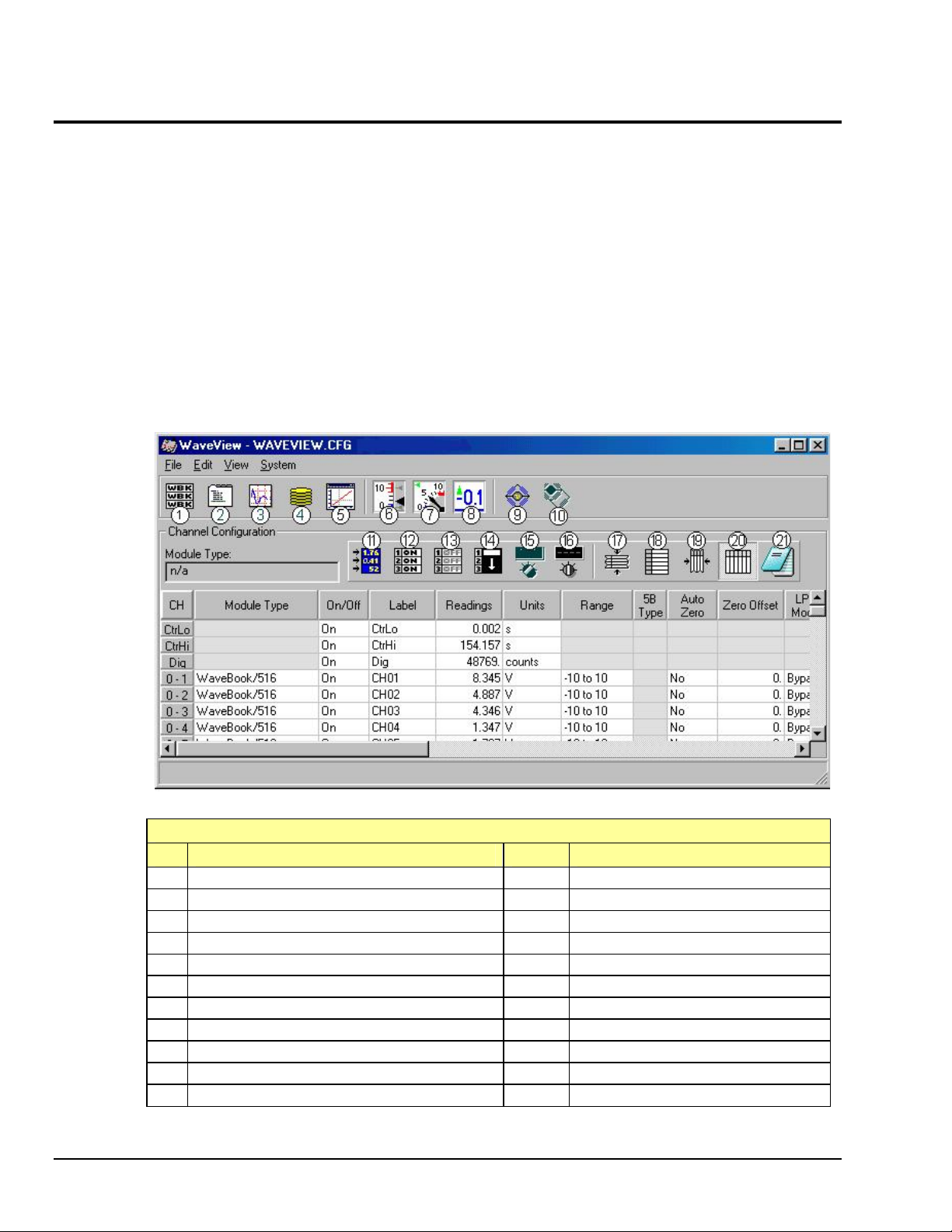
WaveView Out-of-the-Box Software
WaveView is a graphical Windows-based program for use in WaveBook applications. This program allows
users to acquire data for immediate viewing or for storage to the PC's hard disk. WaveView’s
“spread-sheet” style interface makes it easy to set up your application quickly and begin acquiring data
within minutes of completing hardware connections. No programming knowledge is required.
From WaveView you can:
• Set up all analog or digital input parameters.
• Acquire and save data to disk.
• View the acquisition in real-time.
• Send data to other Windows applications, such as spreadsheets and databases.
• Launch an independent, post acquisition data analysis program, such as eZ-PostView to view
and analyze data that was previously acquired with WaveView.
WaveView is detailed in the WaveView_WaveCal.PDF.
WaveView Configuration Main Window
WaveView Configuration Main Window, Button Identification
# Item # Item
1 Module Configuration 12 Make All Channels Active
2 Acquisition Configuration 13 Make All Channels Inactive
3 Scope Window 14 Fill Down
4 Direct to Disk Window 15 Auto Zero Active Channels
5 View File Data 16 Clear All Zero Offsets
6 Bar Graph Meters 17 Hide Inactive Channel Rows
7 Analog Meters 18 Show All Rows
8 Digital Meters 19 Customize Column Layout
9 WBK16 Sensor Calibration 20 Show All Columns
10 WBK16 Shunt Mode 21 Copy Visible Cells to Notepad
11 Enable [Disable] Spreadsheet Readings Column
5-2 Software & Related Documents, An Overview 897895 WaveBook User’s Manual
 Loading...