

Page 1

WaveBook
User's Manual
High-Speed Portable Data Acquisition Systems
• WaveBook/512
• WaveBook/512H
• WaveBook/516
• Related WBKs, DBKs, and Software
the smart approach to instrumentation ™
IOtech, Inc.
25971 Cannon Road
Cleveland, OH 44146-1833
Phone: (440) 439-4091
Fax: (440) 439-4093
E-mail: sales@iotech.com
Internet: www.iotech.com
WaveBook
High-Speed Portable Data Acquisition Systems
Various Models, Software, and System Expansion
p/n
User's Manual
481-0901
Rev.
3.0
© 1999 by IOtech, Inc. July 1999 Printed in the United States of America
Page 2

Page 3
Warranty Information
Your IOtech warranty is as stated on the product warranty card. You may contact IOtech by phone,
fax machine, or e-mail in regard to warranty-related issues.
Phone: (440) 439-4091, fax: (440) 439-4093, e-mail: sales@iotech.com
Limitation of Liability
IOtech, Inc. cannot be held liable for any damages resulting from the use or misuse of this product.
Copyright, Trademark, and Licensing Notice
All IOtech documentation, software, and hardware are copyright with all rights reserved. No part of this product may be
copied, reproduced or transmitted by any mechanical, photographic, electronic, or other method without IOtech’s prior
written consent. IOtech product names are trademarked; other product names, as applicable, are trademarks of their
respective holders. All supplied IOtech software (including miscellaneous support files, drivers, and sample programs)
may only be used on one installation. You may make archival backup copies.
FCC Statement
IOtech devices emit radio frequency energy in levels compliant with Federal Communications Commission rules (Part 15)
for Class A devices. If necessary, refer to the FCC booklet How To Identify and Resolve Radio-TV Interference Problems
(stock # 004-000-00345-4) which is available from the U.S. Government Printing Office, Washington, D.C. 20402.
CE Notice
Many IOtech products carry the CE marker indicating they comply with the safety and emissions standards of the
European Community. As applicable, we ship these products with a Declaration of Conformity stating which
specifications and operating conditions apply.
Warnings, Cautions, Notes, and Tips
Refer all service to qualified personnel. This caution symbol warns of possible personal injury or equipment damage
under noted conditions. Follow all safety standards of professional practice and the recommendations in this manual.
Using this equipment in ways other than described in this manual can present serious safety hazards or cause equipment
damage.
This warning symbol is used in this manual or on the equipment to warn of possible injury or death from electrical
shock under noted conditions.
This ESD caution symbol urges proper handling of equipment or components sensitive to damage from electrostatic
discharge. Proper handling guidelines include the use of grounded anti-static mats and wrist straps, ESD-protective
bags and cartons, and related procedures.
This symbol indicates the message is important, but is not of a Warning or Caution category. These notes can be of
great benefit to the user, and should be read.
In this manual, the book symbol always precedes the words “Reference Note.” This type of note identifies the location
of additional information that may prove helpful. References may be made to other chapters or other documentation.
Tips provide advice that may save time during a procedure, or help to clarify an issue. Tips may include additional
reference.
Specifications and Calibration
Specifications are subject to change without notice. Significant changes will be addressed in an addendum or revision to
the manual. As applicable, IOtech calibrates its hardware to published specifications. Periodic hardware calibration is
not covered under the warranty and must be performed by qualified personnel as specified in this manual. Improper
calibration procedures may void the warranty.
Quality Notice
IOtech has maintained ISO 9001 certification since 1996. Prior to shipment, we thoroughly test our products and
review our documentation to assure the highest quality in all aspects. In a spirit of continuous improvement, IOtech
welcomes your suggestions.
Page 4

Your WaveBook order was carefully inspected prior to shipment. When you receive your
system, carefully unpack all items from the shipping carton and check for physical signs of
damage that may have occurred during shipment. Promptly report any damage to the
shipping agent and your sales representative. Retain all shipping materials in case the unit
needs returned to the factory.
Page 5
How To Use This Manual
This manual pertains to setup and operation of WaveBook data acquisition systems as indicated in the following
chapter descriptions.
Quick Start: Provides instructions for getting a basic WaveBook system connected, powered-up, and collecting
data with use of WaveView software.
Chapter 1: WaveBook Overview describes basic system features and operation. Includes a system block
diagram, introduction to out-of-the-box software, and recommendations regarding software drivers.
Chapter 2: Setup Notes and System Testing provides information regarding hardware connections and system
testing.
Chapter 3: WBK Expansion Options describes the various WBK devices that interface with the WaveBook for
expansion and signal conditioning. The discussion includes block diagrams, setup procedures, operation,
and software concerns.
Chapter 4: System Power & Assembly discusses power supplies and ways of mounting system modules.
Chapter 5: WaveView pertains to WaveBook’s primary software program. This chapter explains how to
configure the software to meet your system requirements.
Chapter 6: PostView explains how to use this program for post-acquisition data viewing.
Chapter 7: Calibration discusses WaveBook’s calibration software. Both automatic and manual calibrations
are discussed.
Chapter 8: Theory of Operation explains a variety of concepts, including: initial acquisition steps, scans, signal
processing, trigger types, and data transfer.
Chapter 9: Troubleshooting suggests solutions to certain technical problems. Please refer to this chapter before
calling for technical assistance.
Appendix A: Accessories, Specifications, & Abbreviations includes a list of the available accessories and
options for the WaveBook system and a list of the physical and performance specifications for related
products. The Abbreviations includes acronyms and ASCII control codes.
Appendix B: this appendix presently lists data acquisition terms and definitions.
Appendix C: contains daqX API programming models. This appendix is intended for users wishing to create
their own applications programs.
Appendix D: contains daqX API command references. This appendix is intended for users wishing to create
their own applications programs.
CAUTION
CAUTION
CAUTIONCAUTION
Using this equipment in ways other than described in this manual can cause personal injury or
equipment damage. Pay special attention to all cautions and warnings.
If you plan to create your own applications programs refer to Appendices C and D. These
two appendices contain API information, including program examples.
WaveBook User’s Manual,
Reference Note:
Additional information (not available at the time of publication), can be found in a
file, or in supplemental documentation.
6-23-99
README.TXT
i
Page 6

Table of Contents
Quick Start …… QS-1
Connect WaveBook to the Host PC …… QS-1
Connect Signals …… QS-2
Connect Power …… QS-3
Install Software …… QS-3
Test Your System ……QS-4
Start WaveView and Collect Data …… QS-4
1 – WaveBook ar Overview
Hardware Overview…… 1-1
Product Comparison......1-1
WaveBook Features …… 1-2
Block Diagrams and Board Layouts……1-3
Software Overview...... 1-6
WaveView Features......1-6
Programming Environments…… 1-8
2 – Setup Notes and System Testing
Hardware Setup Notes …… 2-1
WBK20A – PCMCIA/EPP Interface Card …… 2-1
WBK21 – ISA/EPP Interface Card …… 2-2
Optional Printer Connection ……2-4
Analog-Signal Connections & Grounds ……2-4
Digital I/O Connection
(WaveBook/512 and /512H Only) ……2-5
Digital I/O Connection
(WaveBook/516 Series Only) ……2-5
Pulse Trigger Connection
(WaveBook/516 Series Only) ……2-6
System Testing …… 2-6
3 - WBK Expansion Options
Using Shielded BNC Connectors
for CE Compliance ……3-1
WBK10/10H – Expansion Modules…… 3-2
WBK11 – SSH Card…… 3-6
WBK12/13 – Programmable LPF Cards…… 3-8
WBK14 - Dynamic Signal Input Module… 3-10
WBK15 - 5B Isolated Signal-Conditioning
Module…… 3-17
WBK16 - Strain-Gage Module…… 3-22
WBK30 - WaveBook Memory Option… 3-45
WBK61/62 - High-Voltage Adapters…… 3-43
4 - System Power & Assembly
Power Management…… 4-1
Calculating the System Power Requirement…… 4-1
CA-115 & CA-116 Power Cable Connections…. 4-3
DBK30A – Rechargeable Battery Module…… 4-4
Hardware Setup…… 4-5
DBK30A - Specifications…… 4-6
DBK34 - Vehicle UPS Module…… 4-7
Hardware Setup…… 4-8
DBK34 - Specifications…… 4-9
Stacking Modules…… 4-10
5 – WaveView
Introduction…… 5-1
Software Startup & Sample Acquisition… 5-2
Startup WaveView…… 5-2
Configure Channels…… 5-3
Configure Acquisition…… 5-4
Collect Data…… 5-5
Store Data…… 5-6
WaveView Configuration Main Window… 5-6
Menu Items & Buttons…… 5-6
File…… 5-7
Edit…… 5-7
View…… 5-7
System…… 5-7
Input Channel Configuration…… 5-9
Acquisition Configuration…… 5-11
General Information ……5-11
Trigger Types ……5-11
Expanded Acquisition Features, WaveBook/516
Only…… 5-13
Counter-Timer ……5-13
Digital Pattern Trigger ……5-13
Pulse Trigger …… 5-14
WaveView Scope Window…… 5-15
Menu Items & Buttons…… 5-16
File…… 5-16
Acquire…… 5-16
Charts…… 5-16
Options…… 5-16
Window…… 5-16
Scope Display…… 5-17
WaveView Direct-To-Disk Window…… 5-18
File…… 5-18
Acquire…… 5-18
Window…… 5-19
Data Destination Area…… 5-19
ii WaveBook User’s Manual
Page 7

6 - PostView
Data File Accessibility…… 6-1
Starting PostView…… 6-3
Toolbar…… 6-4
Channel Information Region…… 6-5
Menu Items…… 6-6
Understanding Groups, Charts & Channels……
6-7
Chart Setup Wizard…… 6-7
Introduction…… 6-7
Automatic Display Creation…… 6-8
Display Configuration…… 6-9
Editing a Display…… 6-10
Manually Creating a Display…… 6-12
PostView Timebase…… 6-15
7 - Calibration
Two Methods of Calibration…… 7-1
WaveCal…… 7-1
Configuring System Calibration…… 7-2
Performing System Calibration…… 7-3
Manual Calibration…… 7-4
Trigger Operation…… 8-10
Digital Trigger & Single-Channel Trigger… 8-10
Hysteresis……8-11
Multi-Channel Trigger…… 8-12
Multi-Channel Trigger Types…… 8-12
Above-Level Trigger…… 8-13
Below-Level Trigger…… 8-13
Above-Level-With-Latch Trigger…… 8-13
Below-Level-With-Latch Trigger…… 8-13
Rising-Edge Trigger…… 8-14
Falling-Edge Trigger…… 8-14
Rising-Edge-With-Latch Trigger…… 8-14
Falling-Edge-With-Latch Trigger…… 8-14
Trigger Latency & Jitter…… 8-14
Data Processing…… 8-15
Data Packing (WaveBook/512 Only)…… 8-16
Data Transfer…… 8-17
Time-Outs…… 8-17
Buffer Size and Type…… 8-17
Overlapped Execution…… 8-19
Foreground-Linear Transfers…… 8-19
Foreground-Circular Transfers…… 8-20
Background-Linear Transfers…… 8-20
Background-Circular Transfers…… 8-21
Direct-to-Disk Transfers…… 8-21
9 – Troubleshooting
8 - Theory of Operation
Introduction…… 8-1
Acquisition Steps…… 8-2
Initialize the WaveBook…… 8-2
One-Step Acquisitions…… 8-2
Configure an Acquisition…… 8-2
Channel Numbering…… 8-2
Specifying the Scan…… 8-2
Specifying the Trigger Source…… 8-3
Specifying the Number of Scans…… 8-3
Specifying the Scan Rate…… 8-3
Start the Acquisition…… 8-4
Transferring Results…… 8-4
Stop the Acquisition…… 8-4
Shut Down the WaveBook…… 8-4
Signal Processing…… 8-5
WaveBook/512…… 8-5
Analog Signal Processing…… 8-5
Digital I/O Signal Processing…… 8-5
WaveBook/516 …..8-7
Analog Signal Processing…… 8-7
Digital I/O Signal Processing…… 8-7
Acquisition Operation…… 8-8
Acquisition Modes…… 8-8
N-Shot Acquisition Mode…… 8-8
Infinite Post-Trigger Acquisition Mode…… 8-8
N-Shot with Re-Arm Acquisition Mode…… 8-8
Pre/Post-Trigger Acquisition Mode…… 8-9
Scan Composition…… 8-9
Scan Period…… 8-9
External Clock Input (WaveBook/516 Only) …..8-10
Radio Interference Problems…… 9-1
Electrostatic Discharge (ESD) Damage… 9-1
WaveBook W95/WNT Driver Readme File
(Readmew.txt)…… 9-1
Overview…… 9-2
Driver Support…… 9-2
Connection Problems…… 9-2
32-Bit WaveView Issues…… 9-3
Windows NT V3.51…… 9-3
Windows 95/98 Problems…… 9-3
Resource Settings…… 9-3
Parallel Port Setup…… 9-4
Appendices
A - Accessories, Specifications, &
Abbreviations
B - Acquisition Terms
C - daqX API – Programming Models
D - daqXAPI – Command Reference
WaveBook User’s Manual,
6-23-99
iii
Page 8

iv WaveBook User’s Manual
Page 9
Quick Start
Connect WaveBook to the Host PC …… QS-1
Connect Signals …… QS-2
Connect Power …… QS-3
Reference Note: These Quick Start instructions are for use with basic setups. For complex systems, you may
need to refer to additional text in this manual, or to separate documentation. You may want to refer to the
following:
• Chapter 1 – contains software and hardware overviews.
•
Chapter 2 – pertains to connections and system testing.
• Chapter 3 – discusses WBK units.
• Chapter 4 – pertains to system power use and mechanical assembly options.
• If using the WBK20A or WBK21, refer to separate instructions, supplied with the WBK device.
1. Connect WaveBook to the Host PC
WARNING
WARNING
WARNINGWARNING
Electrical Shock Hazard! Perform all hardware setups with all power off to the device serviced
and to all connected equipment; otherwise, personal injury may result.
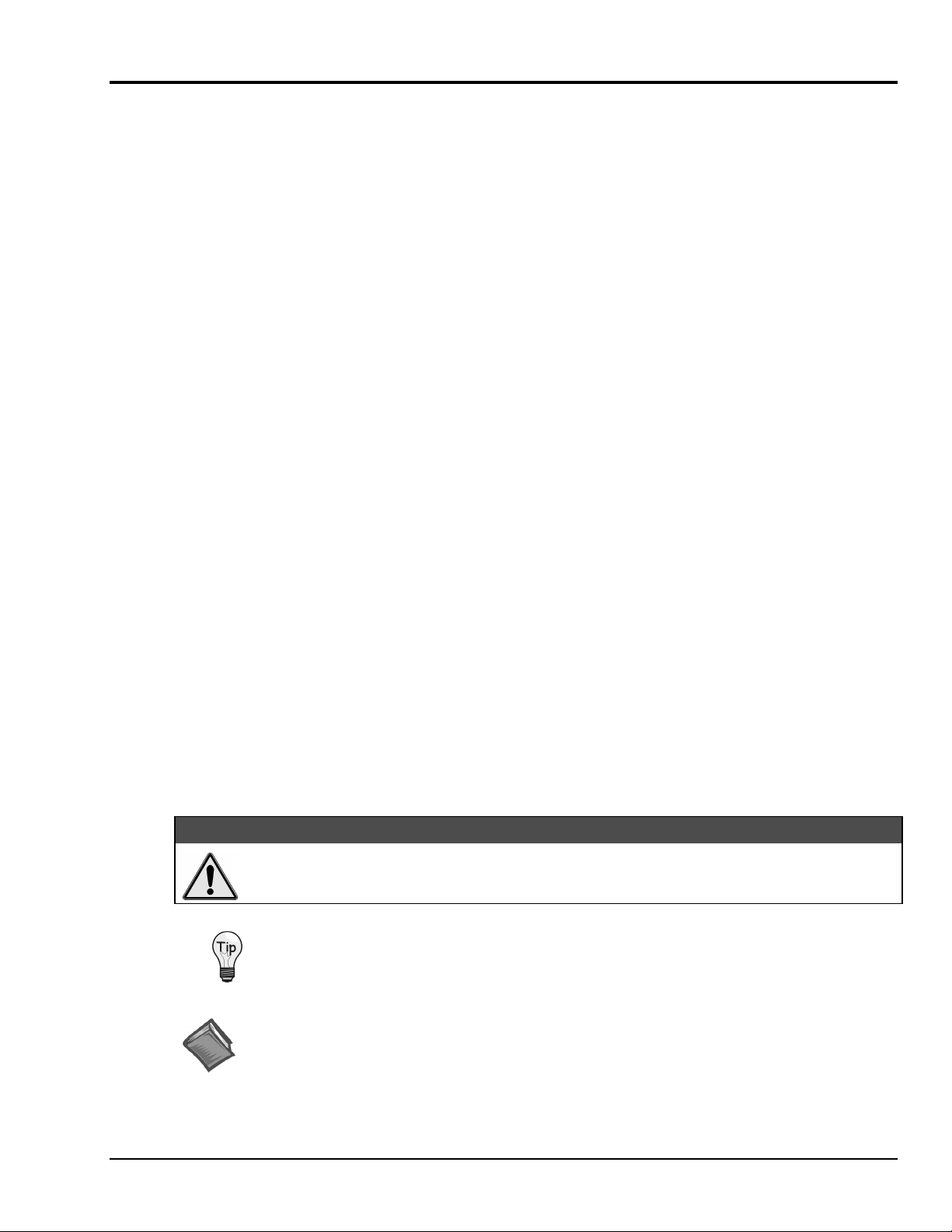
WaveBook connects to a host NoteBook or desktop PC through a 25 pin (male connector) located on the
rear panel. The connector is labeled “To Computer.” A simple illustration of the rear panel follows.
WaveBook rear panels have the following components:
Install Software …… QS-3
Test your System …… QS-4
Start WaveView and Collect Data …… QS-4
Note: Height dimension for WaveBook/516 is 1.75"; WaveBook/512 is 1.38".
• 1 POWER switch (0-off; 1-on)
•
2 circular 5-pin DIN connectors for POWER IN and POWER OUT (pass-through)
•
1 DB25F for TO PARALLEL PRINTER (pass-through) connection
• 1 DB25M for TO COMPUTER (LPT/EPP host) connection
• 1 HD-15F EXPANSION CONTROL output
•
1 BNC connector for analog input EXPANSION SIGNAL IN
WaveBook can be set up to work with Notebook or desktop PCs as follows:
Notebook PCs – Wavebook communicates with a Notebook PC through the PC’s parallel port, or its PC-Card port
using a WBK20A PCMCIA/EPP interface-card.
Desktop PCs - WaveBook communicates with a desktop PC through the PC’s parallel port, or its ISA bus using a
WBK21 ISA/EPP interface-board.
a. Connect the matching end of the supplied communications cable to the computer’s parallel or interface port.
b. Connect the other end of the communications cable to the WaveBook port labeled “TO COMPUTER.”
Desktop PC with WBK21 ISA/EPP
WaveBook/516
POWER
MADE IN USA
POWER IN POWER OUT
TO PARALLEL PRINTER
(+10VDC TO +30VDC)
DB25M Connector “
(links to LPT/EPP on host PC)
TO COMPUTER
Desktop PC (with WBK21) Connected to WaveBook/516
EXPANSION
EXPANS ION
CONTROL
SIGNAL IN
TO COMPUTER
”
WaveBook User’s Manual,
6-24-99
Quick Start QS-1
Page 10
2. Connect Signals
Voltages applied to WaveBook's BNC connectors must not exceed ±35 VDC.
Exceeding these specifications could result in equipment damage.
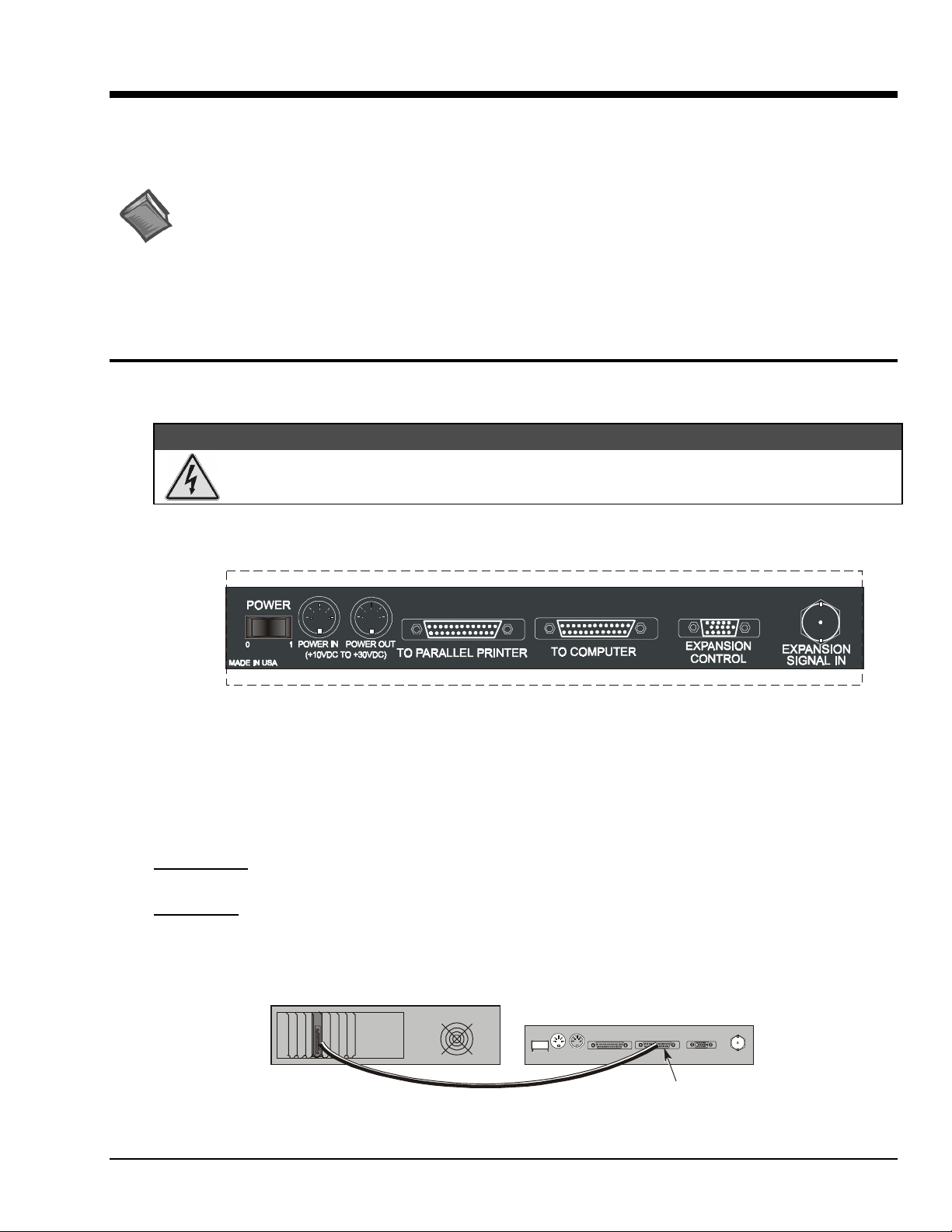
Signal connections are made on the WaveBook’s front panel. The front panels of the WaveBook/512 and
WaveBook/516 are similar. The /516 is taller and has one extra BNC connector (used for pulse trigger).
WaveBook/512 front panel has the following components:
• 1 Binding post for ANALOG COMMON reference
• 8 BNC connectors for analog inputs (analog channel 1 is also the low-latency analog trigger)
•
1 DB25F for DIGITAL I/O TRIGGER input
• 3 Status LEDs (ACTIVE, READY, POWER)
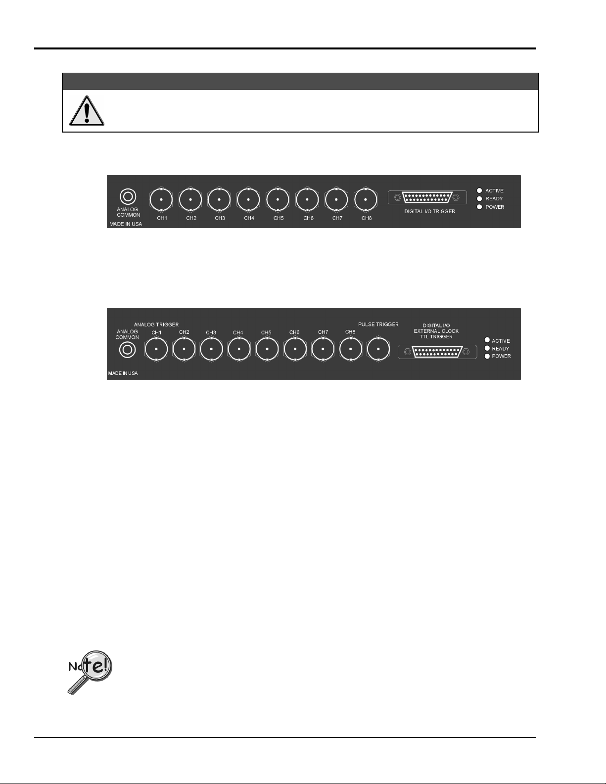
The WaveBook/516 front panel has the following components:
CAUTION
CAUTION
CAUTIONCAUTION
• 1 Binding post for ANALOG COMMON reference
•
8 BNC connectors for analog inputs (analog channel 1 is also the low-latency analog trigger)
• 1 BNC connector for PULSE TRIGGER input
• 1 DB25F for DIGITAL I/O including trigger input and EXTERNAL CLOCK input
• 3 Status LEDs (ACTIVE, READY, POWER)
WaveBook’s front panel has eight BNC connectors for analog inputs, a binding post for analog common,
and a DB25F connector for Digital I/O. Channel 1 is also used for low-latency analog triggering.
WaveBook/516 has an additional BNC connector for pulse trigger.
The center pin of each BNC connector is the high input and the outer shell is the low input. The inputs are
differential, the measured voltage being the difference between the high and low signal levels.
For proper operation, each analog input signal (high or low) must be within ±11 V of the WaveBook's
analog common level.
A few notes regarding ground, follow. Refer to Chapter 2 for more detailed information.
•
When connected, WaveBook’s ANALOG COMMON is at the same potential as the host PC’s digital
ground.
•
WaveBook’s analog channels are not isolated from the host PC.
• WaveBook’s power supply input is isolated from the rest of the WaveBook, including the
ANALOG COMMON and the PC’s digital ground.
For WaveBook [or WBK10/10H] to correctly measure analog signals, each signal must be within
±11 volts of ANALOG COMMON. Refer to Chapter 2 for detailed information.
QS-2 Quick Start,
6-24-99
WaveBook User’s Manual
Page 11

3. Connect Power
WaveBook can be powered from the included wall-mount AC adapter (TR-40U) or from a 10 to 30 VDC source, such
as a car battery. The AC adapter plugs into a standard wall outlet, and its DIN5 end plugs into the DIN5 “Power In”
receptacle on WaveBook’s rear panel.
AC Adapter Connection
Power options include the DBK30A (a rechargeable battery module) and the DBK34 (uninterruptible power supply
module).
Reference Note: If using DBK30A or DBK34, refer to the following sections of your user’s manual for
additional information.
• Chapter 3, WaveBook Expansion Options
• Chapter 4, System Power & Assembly
4. Install Software
WaveBook software includes WaveView, a Windows-based data acquisition program. For successful operation, your
computer should have the following, as a minimum:
• Microsoft Windows 95/98/NT
• 5x86 or Pentium
•
16 Mbytes of RAM (32 Mbytes recommended)
Remove any previous-installed version of the WaveBook drivers before installing a new version.
Install software according to the following procedure.
1. Close all other programs. Use the Microsoft Windows Run dialog box and direct Windows to the
found on Disk 1 (or CD-ROM, if applicable). Follow the on-screen dialog boxes to complete the installation.
2. When the installation is complete, check the WaveBook program group and verify all programs are present.
®
processor
SETUP.EXE file
WaveBook User’s Manual,
6-24-99
Quick Start QS-3
Page 12
5. Test your System
After software installation, the hardware must be tested to verify communication between the PC and the WaveBook.
To test hardware performance, the software installs the Daq Configuration applet into the Windows Control Panel.
This tests the PC parallel port (or WBK20/21 interface) capabilities, and then estimates the maximum performance,
using both standard and enhanced protocols. Testing also verifies that the WaveBook is properly attached and ready to
operate.
To run the WaveBook test program:
1. Ensure the WaveBook is connected to the host computer, and both devices are powered-on.
2. Double-click on the Daq Configuration applet (in the Windows Control Panel).
3. Select the WaveBook device.
4. Click on Properties.
5. Click on the Resource Test button (within the Test Hardware tab).
The program performs several tests on the PC and WaveBook and displays the results. Once communication (between
PC and WaveBook) has been established, you can start WaveView and begin to collect data.
6. Start WaveView and Collect Data
WaveView is a Windows-based application that enables you to acquire data for immediate viewing or for storage to PC
hard disk. No programming knowledge is required.
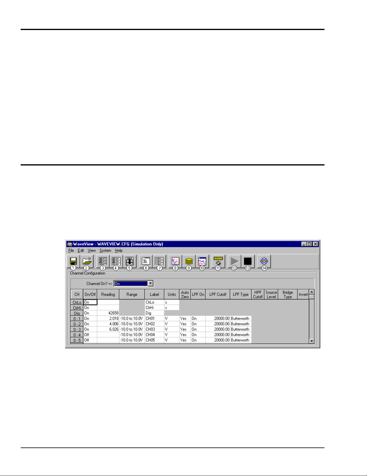
1. Start WaveView by double-clicking on its icon. The WaveView Configuration window appears
(see following figure).
Note: WaveView interrogates the hardware to see what options and expansion modules are connected to the
WaveBook. The total number of channels displayed on the configuration menu corresponds to the number
of channels connected.
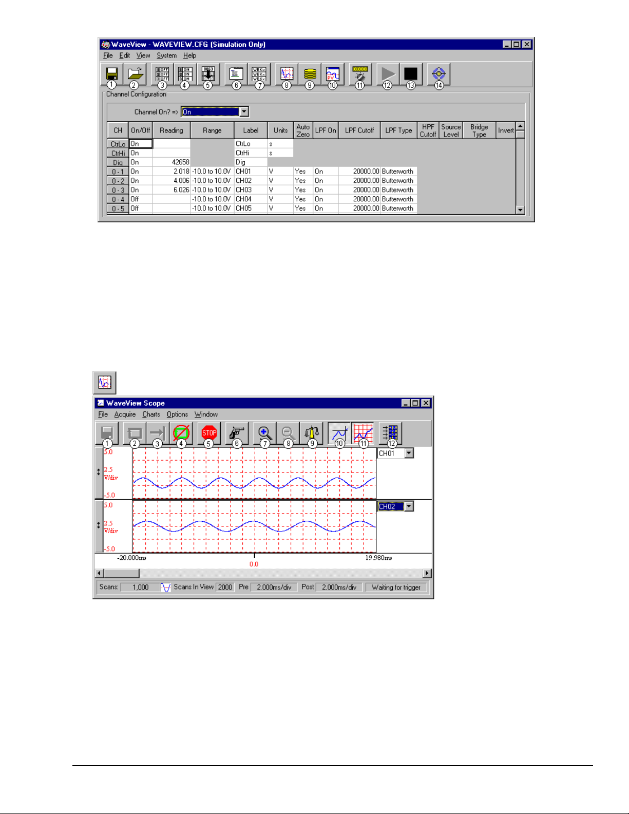
WaveView Configuration Window
Item Description Item Description
1 Save Configuration 8 Open Scope Window
2 Load Configuration 9 Open Direct to Disk
3 Turn All Channels Off 10 Launch PostView with Latest Acquisition File
4 Turn All Channels On 11 Auto Zero Enabled Channels
5 Fill Down 12 Enable Spreadsheet Reading Column
6 Open Acquisition Configuration Dialog 13 Disable Spreadsheet Reading Column
7 Open Module Configuration Dialog 14 Open WBK16 Sensor Calibration Window
QS-4 Quick Start,
6-24-99
WaveBook User’s Manual
Page 13
2. Turning on a channel allows it to be sampled during an acquisition. To begin acquiring data with WaveView, turn on only
those channels that have signal connections. You can do this by either of the following methods:
(a) Double-click on the channel’s “On/Off” cell to select the proper status. This action toggles the On/Off status.
or
(b) Click once on the channel’s “On/Off” cell, then select “On” or “Off” from the listbox above the spreadsheet.
3. Select the appropriate parameters for each channel. The spreadsheet entries can be changed for all channels by clicking
once on the column label at the top of the spreadsheet to highlight the column, and then making the appropriate entry
within the selection box that appears above the spreadsheet:
• Gain and offset are selected by choosing an entry from the Range entry box.
• A name may be assigned to each channel by editing the Label box for that channel.
•
Volts, millivolts, or mX+b for each channel may be selected within the Units column.
4. Select Acquisition Configuration from the View pull-down menu. When the Acquisition Configuration window is
displayed, enter values for Pre-trigger, and/or Post-trigger [scans or time periods] as desired. The timebase for the
acquisition can be set to Frequency or Period. The desired trigger source and parameters are selected in the Trigger
selection box.
5. To read data from WaveBook:
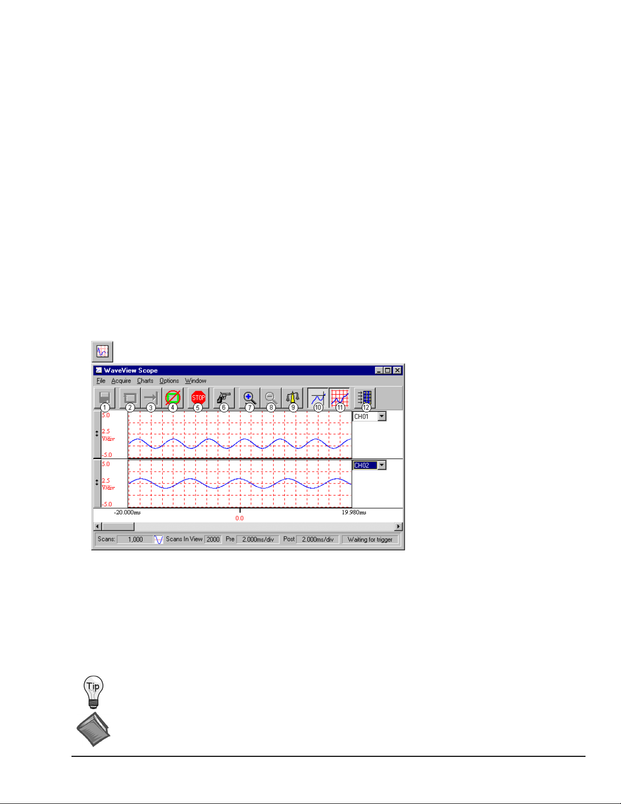
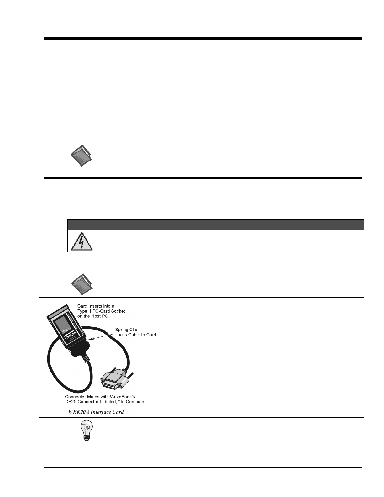
(a) Select Scope from the View pull-down menu. (The next figure shows a sample Scope screen).
(b) Click the Acquire One Shot button, or the Acquire Continuously button.
(c) Click the Manual Trigger button.
6. If desired, save collected data to disk by clicking on the Save button (“floppy disk” icon (1)),
or use the save option in the File pull-down menu.
WaveView Scope Button and Window
Item Description Item Description
1 Save Data 7 Zoom In
2 Acquire Auto-Rearm 8 Zoom Out
3 Acquire One Shot 9 Scale All Charts
4 Stop After Acquisition Complete 10 Toggle Cross Hairs
5 Stop Immediately 11 Toggle Grids
6 Manual Trigger 12 Open Configuration Window
To view additional channels in Scope Display, simply change the entry in the Number of Charts selection
of the Charts pull-down menu. In Scope Display, you can simultaneously view up to eight channels.
Reference Note:
For detailed WaveView information, refer to Chapter 5.
Chapter 5 includes material on WaveView Scope.
WaveBook User’s Manual,
6-24-99
Quick Start QS-5
Page 14

QS-6 Quick Start,
6-24-99
WaveBook User’s Manual
Page 15

WaveBook Overview 1
Hardware Overview…… 1-1
Product Comparison......1-1
WaveBook Features......1-2
Block Diagrams and board Layouts…… 1-3
WaveBook/512 and 512H......1-4
WaveBook/516……1-5
Hardware Overview
Product Comparison
High resolution and high-speed signal capture make WaveBooks an ideal choice for a variety of
applications, such as testing engine strain, multi-channel acoustics, mechanical integrity, and
vibration/shock/strain.
As listed in the following table, the WaveBook series presently includes three models. Each provides
1 MHz sampling and supports the WBK expansion options described in chapter 3.
WaveBook Product Comparison*
Analog Input WaveBook/512 WaveBook/512H WaveBook/516
A/D resolution
A/D speed
Sample rate
Ranges
Unipolar (
Bipolar
A/D accuracy
Data packing
20-kHz low-pass filter
Analog input channels
Differential amplifiers
PGAs
Maximum capacity
FIFO depth
Total Harmonic Distortion
10Hz to 20Khz, Typical
Signal to Noise and Distortion
(SINAD)
High-Speed Digital Inputs
Digital I/O
Timer Input
32-Bit Timer
Trigger
Single and multi-channel
Digital Pattern
Pulse
1
For WaveBook512, the Total Harmonic Distortion (THD) and SINAD values shown apply to the –5 to +5 V range.
For WaveBook512H and /516, the THD and SINAD values apply to the –10 to +10 V range.
2
Unipolar ranges do not apply to WaveBook/512H or WaveBook/516 when a WBK11, WBK12, or W BK13 is installed.
Specifications subject to change without notice.
*
Module Description Module Description
DBK30A
DBK34
WBK10/10H
WBK11
WBK12
WBK13
WBK14
WaveBook User’s Manual
Note 2)
1
Rechargeable battery module
Vehicle Uninterruptible Power Supply module
8-channel Expansion Chassis
Simultaneous Sample & Hold (SSH) Card
Programmable Low-Pass Filter Card
Programmable Low-Pass Filter Card with SSH
Dynamic Signal Conditioning Module
6-25-99
Software Overview......1-6
WaveView Features......1-6
Programming Environments…… 1-8
Standard API (wbk…)…… 1-8
Enhanced API (daq…)…… 1-8
Language Support…… 1-8
12-bit 12-bit 16-bit
1 MHz 1 MHz 1 MHz
1 µs/channel 1 µs/channel 1 µs/channel
0 to +10V, 0 to +5V,
0 to +2V, 0 to +1V
±5V, ±2.5V, ±1V, ±0.5V
±0.025% FS ±0.025% FS ±0.012% FS
44
optional optional
8 DE 8 DE 8 DE
1 (shared by all 8 inputs) 1 (shared by all 8 inputs) 8 (1 per analog input)
1 (shared by all 8 inputs) 1 (shared by all 8 inputs) 1 (shared by all 8 inputs)
72 Channels 72 Channels 72 Channels
64K samples 64K samples 64K samples
1
-78dB -78dB -84dB
-66dB -66dB -74dB
8816
None None
444
None None
None None
0 to +10V, 0 to +4V,
0 to +2V
±10V, ±5V, ±2V, ±1V
WBK15
WBK16
WBK20A
WBK21
WBK30
WBK61/62
(Note 2)
8-Slot 5B Signal Conditioning Module
Strain-Gage Module
PC-card / parallel port interface and cable
ISA/EPP Interface Plug-in Board
WaveBook Memory Option
High-Voltage Adapter and Probes
0 to +10V, 0 to +4V,
0 to +2V
±10V, ±5V, ±2V, ±1V
For 12-bit resolution only
WaveBook Overview 1-1
(Note 2)
4
4
4
4
Page 16

WaveBook Features
WaveBook features include:
• Power Options: Power can be supplied from an AC-to-DC adapter, battery, DBK30A rechargeable
battery module, or DBK34 uninterruptible power supply module.
• Easy Connection to Notebook or Desktop PCs.
• Analog Input Channels: BNC connectors keep input signals isolated from the chassis and commons.
• High-Speed Digital Inputs: 8 high-speed digital inputs (16 for WaveBook/516).
• Digital Signal Processing (DSP): Allows you to define a channel scan-sequence and associated gains
across all channels. Also provides for real-time digital calibration on a per-sample basis.
• Programmable Scan Sequencing: A 128-location scan sequencer allows you to program the analog
channel scan sequence, the associated unipolar/bipolar A/D range, and the input amplifier gain.
WaveBook performs 1 MHz scanning and gain switching over both its built-in and expansion channels.
• Single, or Multi-Channel Triggering
• Pre- and Post-Trigger Readings
• Digital-Pattern Trigger (WaveBook/516 Series Only): Trigger occurs when a Digital I/O pattern is
equal too, not-equal too, greater than, or less than a user-defined 16-bit digital pattern. This is useful
when trying to capture noise, vibrations or some other physical disturbance that occurs at a particular
point in a digitally-sequenced process, such as a relay-logic-control system. Trigger latency of the
digital pattern trigger is less than 200 ns for post-trigger acquisitions.
• Pulse Trigger (WaveBook/516 Series Only): Enables triggering and the correlation of lower-speed
waveforms with the occurrence of a user-defined, high-speed pulse.
• 20 kHz Low Pass Filter (WaveBook/516 Series Only): Each of the eight channels has its own low
pass, anti-alias filter.
• External Clock Input (WaveBook/516 Series Only): The external clock is useful when data collection
depends on rotational speed or axial position. Note that the external clock’s input can be reset to a
slower rate.
Reference Note:
In regard to WaveBook expansion options, refer to chapter 3.
1-2 WaveBook Overview,
6-25-99
WaveBook User’s Manual
Page 17

WaveBook Block Diagrams and Board Layouts
Reference Notes: Pages 1-4 and 1-5 contain the functional block diagrams and board layouts for
WaveBook/512, WaveBook/512H, and WaveBook/516. Chapters 3 and 4 include block diagrams for
WBKs and DBKs, respectively. Simple board layouts have been included when considered useful.
The following block diagrams should help you to better understand the information below.
For all three models (/512, /512H, and /516), the analog input signal path proceeds as follows:
• WaveBook/512 and WaveBook/512H: Each of the 8 pairs of differential signals (one per BNC
connector) is buffered and then switched by the channel-selection multiplexer.
•
The selected differential pair is then converted to a single-ended signal by the programmable gain
amplifier (PGA). The WaveBook/512 has gain factors of ×1, ×2, ×5, or ×10 (corresponding to input
ranges of 10, 5, 2, or 1 volts). The /512H gain factors are similar.
•
WaveBook/516: Each of the 8 pairs of differential signals (one per BNC connector) is buffered and
applied to a differential amplifier. The output of each differential amplifier is applied to a 5 pole, low
pass filter. The 8 channels and their low pass signals are then switched by the channel-selection
multiplexer into a the programmable gain amplifier (PGA). The WaveBook/516 has gain factors of
×1, ×2, ×5, or ×10 (corresponding to input ranges of 10, 5, 2, or 1 volts).
• The amplified signal is then level-shifted to locate the desired range within the A/D converter's fixed
input range. Two offset settings are available, unipolar and bipolar. Unipolar offset is used for
sampling signals that are always positive. Bipolar offset is used for signals that may be positive or
negative. For example, when a /512, or /516 is set for unipolar at a gain of ×5, the input span is 2 volts
and the amplified signal is offset so that input voltages from 0 to +2 volts can be digitized. When set
for bipolar operation, the offset is adjusted so that input voltages from -1.0 to +1.0 volts can be
digitized.
• The signal is then switched over to the A/D converter. For /512 and /512H units, the A/D converter
digitizes the signal to12 bits in 1 µs. For WaveBook/516, the A/D converter digitizes the signal to
16 bits in 1 µs. Note that the A/D converter's input can be switched to the expansion signal input,
allowing the device to read one of 64 possible expansion channels (supplied by up to eight WBK10
expansion chassis).
The digital signal processor (DSP) processes the digitized value and corrects the value for gain and offset
errors. The DSP places the corrected result into the FIFO data buffer that holds the samples until the PC
reads the data. If the sample is used for triggering, the DSP determines if a valid trigger event has occurred.
The WaveBook also includes low-latency analog or TTL-level triggering. The low-latency analog trigger
detector examines the WaveBook input channel 1 to determine if a trigger has occurred. The selected lowlatency trigger is presented to the control and timing circuit that starts the acquisition after the trigger. The
TTL trigger is taken directly from the digital I/O port.
The control and timing circuit and the DSP together coordinate WaveBook activities. Every sample time,
the DSP reads from the scan sequence table and accordingly programs the control and timing circuit for the
next sample. The control and timing circuit waits precisely until the start of the next sample and then selects
the input channel, the PGA gain, the level-shifter offset, and the A/D input source. It also conveys this
information to any attached expansion units and precisely controls the A/D conversion timing.
WaveBook User’s Manual
6-25-99
WaveBook Overview 1-3
Page 18
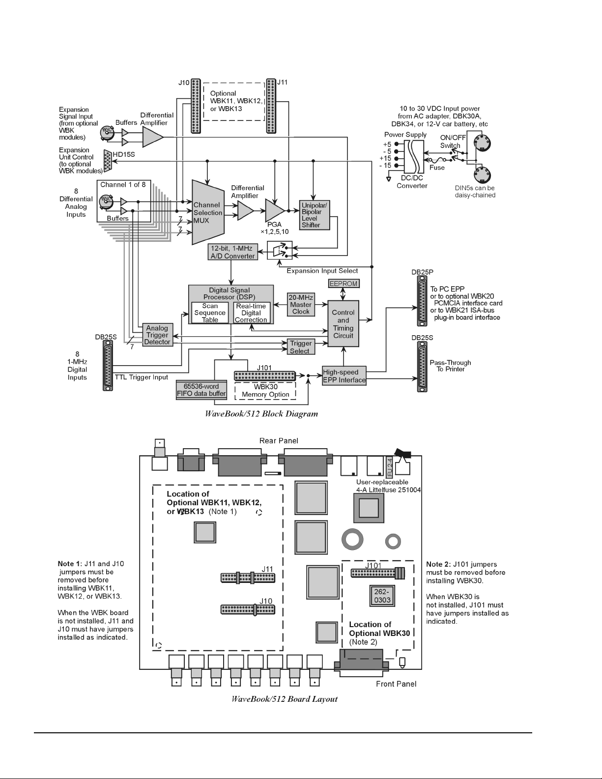
WaveBook/512 and /512H, Block Diagram and Board Layout
The illustrations on this page can be used for both WaveBook/512 and WaveBook/512H.
1-4 WaveBook Overview,
6-25-99
WaveBook User’s Manual
Page 19
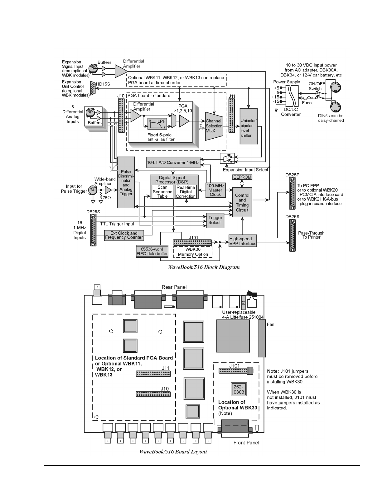
WaveBook/516 Block Diagram and Board Layout
The illustrations on this page only apply to WaveBook/516.
WaveBook User’s Manual
6-25-99
WaveBook Overview 1-5
Page 20

The EEPROM holds the calibration information needed for the DSP-based real-time sample correction.
The digital I/O port is read and written by the DSP to transfer bytes of digital data. It may be used as a
simple 8-bit input port or as a 32-address byte-wide I/O port.
The high-speed EPP interface circuit connects the WaveBook and any attached printer to the PC via
standard DB-25 connectors. When the WaveBook is active, the interface holds the printer in a stable state;
and when the WaveBook is inactive, the interface connects the PC to the printer.
Pin-header J101 allows the addition of the WBK30 memory option. The WBK30 is discussed in chapter 3.
Pin-headers J10 and J11 allow the addition of the optional WBK11, WBK12, or WBK13. These cards can
also be added toWBK10/10H expansion modules.
WaveBook/516’s Fan
To maintain sufficient cooling, it is important to keep the fan and vents free of obstruction.
Note: Partial blocking that results from the use of splice plates does not jeopardize cooling.
Software Overview
WaveBook provides for several software options.
• WaveView, PostView, and WaveCal are the "out-of-the-box" programs included with the hardware.
WaveView provides visual representation of the collected data in real-time or an extended-time view
via PostView. WaveCal uses a 2-pt linear approximation method to calculate gain and offset errors for
each channel..
Reference Note:
WaveView, PostView, and WaveCal are discussed in chapters 5, 6, and 7, respectively.
• DASYLab is a customizable graphical application that allows you more options in designing your
operator interface or performing real-time analysis or control. DASYLab is documented separately.
• Programming environments include standard and enhanced Application Programming Interfaces
(API) with drivers for popular languages. Refer to Appendices C and D for detailed API information.
WaveView Features
WaveView is a Windows-based setup and acquisition program that allows you to configure, display, and
save data to disk within minutes of unpacking the WaveBook. The point-and-click interface simplifies
hardware setup including WBKs without programming or connecting icons. The intuitive control
automatically queries the WaveBook upon connection to your PC. As WBK options are added for signal
conditioning or increased channel count, WaveView's configuration spreadsheet automatically expands to
accommodate them. Specific channel characteristics, such as gain, unipolar/bipolar, and channel labels are
automatically updated. Additional functions (such as low-pass filtering, filter cut-off, or excitation output)
appear in the configuration spreadsheet.
The following two figures show the configuration window and a scope/display window:
1-6 WaveBook Overview,
6-25-99
WaveBook User’s Manual
Page 21
WaveView Configuration Window
Item Description Item Description
1 Save Configuration 8 Open Scope Window
2 Load Configuration 9 Open Direct to Disk
3 Turn All Channels Off 10 Launch PostView with Latest Acquisition File
4 Turn All Channels On 11 Auto Zero Enabled Channels
5 Fill Down 12 Enable Spreadsheet Reading Column
6 Open Acquisition Configuration Dialog 13 Disable Spreadsheet Reading Column
7 Open Module Configuration Dialog 14 Open WBK16 Sensor Calibration Window
WaveView Scope Button and Window
Item Description Item Description
1 Save Data 7 Zoom In
2 Acquire Auto-Rearm 8 Zoom Out
3 Acquire One Shot 9 Scale All Charts
4 Stop After Acquisition Complete 10 Toggle Cross Hairs
5 Stop Immediately 11 Toggle Grids
6 Manual Trigger 12 Open Configuration Window
WaveBook User’s Manual
6-25-99
WaveBook Overview 1-7
Page 22

Programming Environments
Reference Note:
Individuals who want to write their own applications programs should refer to Appendices C and D for
detailed API information.
The install disks (or CD-ROM) include “drivers” to accommodate various programming environments. This
section will help you decide which Application Program Interface (API) and programming language to use
in developing your application. WaveBook applications can be written to either the Standard WaveBook
API or to the Enhanced Daq* API:
• The Standard API has the same format (only written to 32-bit mode) as the 16-bit Windows 3.X version of the
driver. Standard API functions have the specific wbk… prefix.
• The Enhanced API is a newer format that can be used with the WaveBook, DaqBook, DaqBoard, Daq PC-Card
and TempBook product lines. Enhanced API functions share the daq… prefix.
In general:
• You cannot mix standard and enhanced API commands; you must choose one or the other.
• If starting with an existing WaveBook application written to Windows 3.X, the quickest port is to use or rewrite
code to the Standard API.
•
If writing a new application, it is best to write code to the Enhanced API due to its improved performance and
enhanced feature set (see following).
Standard API (wbk…)
The Standard API was originally written for the WaveBook’s Windows 3.X driver. However, it can be
used under Windows 95/98 in 16-bit or 32-bit mode; and under Windows NT in 32-bit mode. The Standard
API is the only API option available for DOS or Windows 3.X applications. The standard API does not
support the WBK30 memory option. You can use the Standard API when:
• developing a new or existing DOS application
• developing a new or existing Windows 3.X application
• a quick port of an existing 16-bit Windows 3.X application to 32-bit mode Windows 95/98/NT is required
Enhanced API (daq…)
The Enhanced API for 32-bit systems has several features that are not present in the Standard API:
•
Multi-device: Can concurrently handle up to 4 devices (including WaveBooks, Daq* products, and/or
TempBooks)
• Larger buffer: Can handle up to 2 billion samples at a time
•
Enhanced acquisition and trigger modes
• Direct-to-disk capabilities
• Wait-on-event features
•
Uses multi-tasking advantages of Windows 95/98/NT
Use the Enhanced API when:
• developing new or existing Windows 95/98 applications
•
developing new or existing Windows NT applications
• using a WBK30 memory option
• porting an existing Standard API application to 32-bit mode to take advantage of the Enhanced API features
Language Support
Enhanced API (or 32-bit Standard)
Supported Languages
C/C++
Microsoft Visual C++
Borland C++ (v4.0 and greater)
BASIC
Microsoft Visual Basic (v4.0 and greater)
Delphi
Borland Delphi (v2.0)
1-8 WaveBook Overview,
When creating your own programs, use the Enhanced API (daq…), if feasible.
Standard API (16-bit)
Supported Languages
C/C++
Microsoft Visual C++
Borland C++ (v4.0 and greater)
BASIC
Microsoft Visual Basic (v4.0 and greater)
QuickBASIC
Pascal
Turbo Pascal
6-25-99
WaveBook User’s Manual
Page 23
Setup Notes and System Testing 2
Hardware Setup Notes …… 2-1
WBK20A – PCMCIA/EPP Interface Card (for linking WaveBook to a Notebook PC) …… 2-1
WBK21 – ISA/EPP Interface Card (for linking W aveBook to a Desktop PC) …… 2-2
Optional Printer Connection ……2-4
Analog-Signal Connections & Grounds ……2-4
Digital I/O Connection (WaveBook/512 and /512H) ……2-5
Digital I/O Connection (WaveBook/516 Series Only) ……2-5
Pulse Trigger Connection (WaveBook/516 Series Only) ……2-6
System Testing …… 2-6
This chapter is intended primarily for users having systems that are beyond the scope of the Quick Start (presented at
the beginning of this manual).
Reference Note: For more advanced system setups, you should refer to the following, as needed.
• Chapter 3 – discusses WBK expansion options.
• Chapter 4 – pertains to system power use and mechanical assembly options.
• If using the WBK20A or WBK21, refer to separate instructions, supplied with that device.
Hardware Setup Notes
If you are connecting your WaveBook to a Notebook PC, you will be using a WBK20A, PCMCIA Interface
Card. If connecting WaveBook to a desktop PC, you will use a WBK21 ISA/EPP Interface Card. Both
interface types are detailed in the following text.
Electrical Shock Hazard! Perform all hardware setups with all power off to the device serviced
and to all connected equipment; otherwise, personal injury may result.
WBK20A - PCMCIA/EPP Interface Card
Reference Note:
WBK20A is shipped with a PC-Card-to-Parallel-Port Adapters User’s Manual.
Refer to that document for installation details.
To link a WaveBook to a Notebook PC using a WBK20A:
1. Insert the WBK20A card into a Type II PCMCIA socket on the Notebook.
2. Connect cable (CA-191-1) to the PCMCIA card.
3. Connect the cable’s DB-25 socket-connector to WaveBook's DB25 plug
connector labeled “TO COMPUTER.”
4. Load the required software drivers by following the instructions provided
with the WBK20A.
Note that no hardware configuration is required. Software configuration is
performed from within the provided software.
WARNING
WARNING
WARNINGWARNING
(for linking WaveBook to a Notebook PC)
Record the WBK20A DMA address and IRQ interrupt settings for future reference.
WaveBook User’s Manual
6-23-99
WaveBook Setup 2-1
Page 24
To ensure proper operation of WBK20A card, you will need to boot up the computer with
the WBK20A inserted in the PC’s card slot. Failure to do so may prevent the application
software from recognizing the card as a parallel port device.
You can use the earlier version WBK20 card/cable to connect your WaveBook to a
Notebook PC. WBK20 is identical to WBK20A in performance, but requires a different
cable (CA-157-1). WBK20A uses cable CA-191-1, which locks to the card.
It is important to note that these two cables are not interchangeable.
WBK20A - Specifications
Specifications are provided in Appendix A.
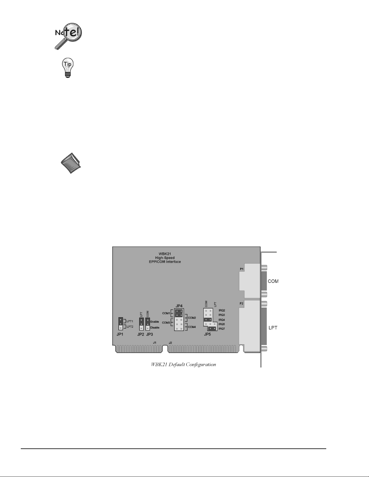
WBK21 - ISA/EPP Interface Card
Reference Note:
WBK21 is shipped with an installation guide. Refer to that document for additional details.
WBK21 is used to link WaveBook to a desktop PC. WBK21 contains the following two ports:
• 2.5 Mbyte/second (enhanced parallel port), often referred to as an LPT printer port.
•
16550 type buffered, high-speed, serial port. Often referred to as serial communication, or COM port.
WBK21 installs into an IBM compatible computer using any available 16-bit ISA bus backplane slot. Prior
to installing the card, make sure it is configured for your preferences. A discussion of card configuration
now follows.
(for linking WaveBook to a Desktop PC)
2-2 WaveBook Setup,
6-23-99
WaveBook User’s Manual
Page 25
WBK21 Jumper Settings
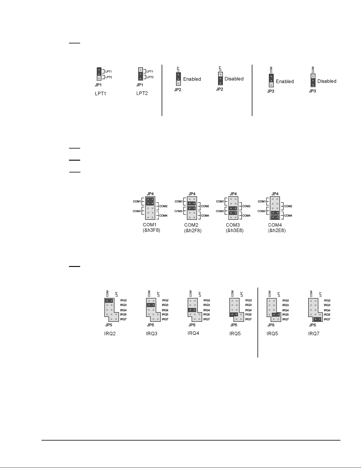
JP1
WBK21 occupies the I/O address space of one parallel printer port (LPT1, LPT2, or LPT3). The factory
default setting (via JP1) is LPT1 (&h378).
If an IBM Monochrome board is not installed, then WBK21 would be designated as LPT1 or LPT2.
JP1 Configurations for
Parallel Port Selection
JP2 Configurations for
Parallel Port Enabled or Disabled
JP3 Configurations for
Serial Port Enabled or Disabled
If an IBM Monochrome display board (with an on-board parallel printer port) is installed in your PC, the
Monochrome printer port will always be designated LPT1 and have an address designation of &h03BC.
Other parallel printer ports (or WBK21s) are then designated as LPT2, or LPT3.
JP2
The JP2 configuration enables (or disables) the parallel port. Enabled is the default.
JP3
The JP3 configuration enables (or disables) the serial port. Enabled is the default.
JP4
JP4’s configuration determines the serial port (COM port) used. COM1 is the default. The COM port that
designates WBK21 depends on two factors: (1) WBK21 configuration, and (2) other installed devices
making use of COM ports.
JP4 Configurations for Serial Port Selection
JP5
In reference to the following figure, the top four jumper positions on JP5 select the serial port IRQ level.
IRQ4 is the default setting. The bottom two jumper rows select the parallel port IRQ level. IRQ7 is the
default parallel port setting. Note that COM and LPT ports cannot both be configured for IRQ5 at the same
time.
After WBK21 is properly configured, power-off your computer and install WBK21 into an available 16-bit
ISA bus. Consult your PC user’s manual as needed.
After WBK21 has been physically installed, power up your PC.
WBK21 - Specifications
Specifications are provided in Appendix A.
WaveBook User’s Manual
6-23-99
JP5 Configurations for Serial Port IRQ Level JP5 Configurations for
Parallel Port IRQ Level
WaveBook Setup 2-3
Page 26
Optional Printer Connection
WaveBook allows for LPT pass-through for printer operation while the WaveBook is connected, but not
operating. When using a printer in the system configuration, attach the original printer cable (plug DB25)
into WaveBook’s connector labeled "TO PRINTER." Note that some software programs, including
WaveView, must be closed to release the driver for printer pass-through operation.
Analog Signal Connections & Grounds
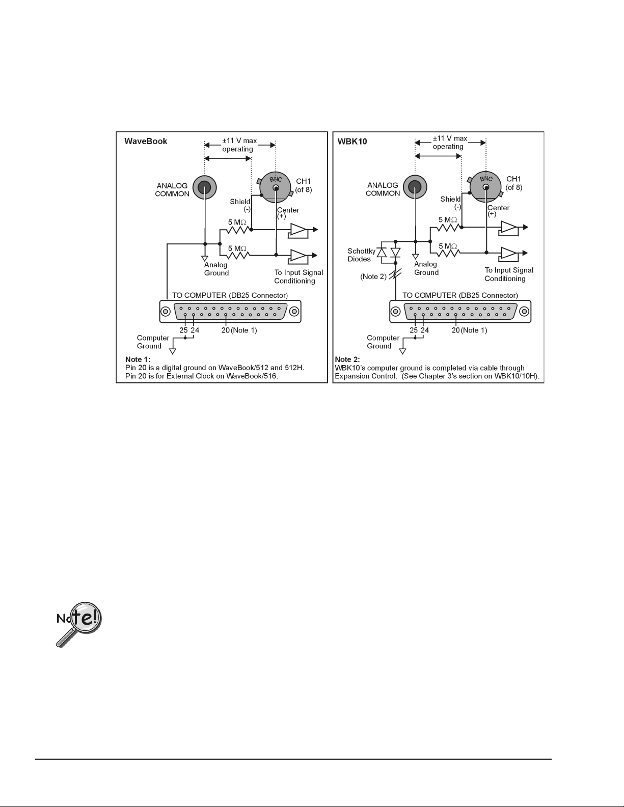
Channel Analog Input, BNC Signal Connections
For each of the eight channel analog inputs, the BNC center (+) and shield (-) are internally connected to
WaveBook’s binding post labeled, ANALOG COMMON. The center (+) and shield (-) each connect to
ANALOG COMMON through a 5 M
Ω
resistor, resulting in a 10 MΩ differential input resistance
(see figures). WaveBook’s ANALOG COMMON connects to the computer power supply ground through
the TO COMPUTER DB25 connector and cable.
•
If the host computer is a desktop PC, then the computer ground will likely connect to the
AC power line ground.
•
If the host computer is a notebook PC, then the computer ground could be:
(a) floating, for example, when operating on batteries, or
(b) connected to a vehicle ground, for example, when using an automotive cigarette lighter adapter in conjunction
with the vehicle’s battery.
Note that a pair of Schottky diodes is used in the WBK10 to clamp the ANALOG COMMON to within
0.3V of computer ground (see figure).
WaveBook and WBK10/10H both have isolated power supplies. Power input common is isolated from
ANALOG COMMON by >10
9
Ω in parallel with 0.1µF.
For WaveBook [or WBK10/10H] to correctly measure analog signals, each signal must be within
±11 volts of ANALOG COMMON. The following notes provide guidelines on how to achieve this.
Like WaveBooks, notebook computers are rarely connected to AC power line ground.
This is true even when these devices are plugged into AC adapters.
Floating Grounds: If the computer is battery operated and the signal source is floating (such as an
Ω
ungrounded sensor), then the internal 5 M
resistors may provide enough of a return path to ANALOG
COMMON. If either the computer or the analog signal source is committed to AC power line ground, then
you will require a direct connection between the signal source and ANALOG COMMON.
When in doubt, connect the signal source common to ANALOG COMMON.
2-4 WaveBook Setup,
6-23-99
WaveBook User’s Manual
Page 27
A single-ended signal source needs to have its common connected to ANALOG COMMON.
When connecting several signal source commons to ANALOG COMMON, it is important that there is no voltage
potential [between these signal source commons]. Otherwise, ground currents will circulate, leading to measurement
errors.
If there is a fixed voltage potential between multiple signal source commons, then only one of these signal source
commons needs connected to ANALOG COMMON. This is true as long as the common mode voltage of any input
does not exceed ±11 volts.
Digital I/O Connection (WaveBook/512 and /512H)*
*Note: The following pinout can be used for WaveBook/516, providing the unit is in the 8-bit mode (instead of 16-bit).
If using this pinout for WaveBook/516 (in 8-bit mode), pin 20 will be assigned to external clock input.
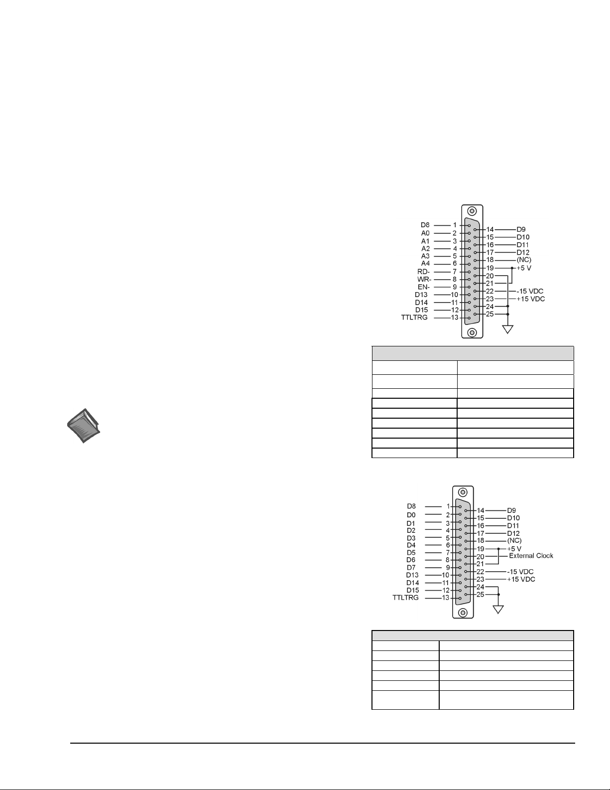
With the WaveBook/512 series, the following signals are present on
the DB25F high-speed digital I/O connector.
•
8 Digital I/O Lines (D8 – D15)
• 5 Address Lines (A0 –A4)
• Active-low Digital I/O Enable output (EN-)
• Active-low Digital I/O Write Strobe (WR-)
• Active-low Digital I/O Read Strobe (RD-)
• TTL Trigger Input (TTLTRG)
• +15 V (pin 23), -15 V (pin 22), 50 mA max. (each)
•
two +5 V power (pins 19 and 21), 250 mA max. (total)
•
three Digital Grounds (pins 20, 24, and 25)
To sample just 8 digital input signals, connect them directly to the
digital I/O data lines. D15 is the most significant bit, and D8 is the
least. The address lines, the read and write strobes, and enable signal
may all be left disconnected.
Reference Note: To use digital I/O address lines
(A0 –A4) to select from up to 32 input bytes, or to use the
digital I/O port for output, refer to chapter 8,
Theory of Operation.
Digital I/O Connections, WaveBook/512
D8-D15 Digital I/O data lines
A0-A4 Digital I/O address lines
EN- Active-low digital I/O enable
RD- Active-low read strobe
WR- Active-low write strobe
TTLTRG TTL trigger input
+5 VDC 250 mA maximum
+15,-15 VDC 50 mA maximum (each)
Digital Grounds Pins 20, 24, and 25
Digital I/O Connection (WaveBook/516 Only) 16-bit mode*
With the WaveBook/516 series, the following signals are present on
the DB25F high-speed digital I/O connector.
•
16 High-Speed Digital I/O Lines (D0 through D15)
• TTL Trigger Input (TTLTRG)
• +15 V (pin 23), -15 V (pin 22), 50 mA max. (each)
• two +5 V (pin 19 and pin 21), 250 mA max. (total)
• External Clock (pin 20)
• two Digital Grounds (pins 24 and 25)
To sample just 16 digital input signals, connect them directly to
the digital I/O data lines. D15 is the most significant bit, and D0
is the least.
*Note: For 8-bit mode, refer to the WaveBook/512 pinout, with noted
exception that pin 20 is for an external clock (with
WaveBook/516).
Note: The following figure depicts WaveBook/516’s Front Panel,
showing the DB25 connector and cable for External Clock and
TTL External Trigger.
WaveBook User’s Manual
6-23-99
D0 – D15 High Speed Digital I/O data lines
TTLTRG TTL trigger input
External Clock 16 bit mode, read/write strobe
+5 VDC 250 mA maximum
+15,-15 VDC 50 mA maximum (each)
Digital Grounds Pins 24 and25
Digital I/O Connections, WaveBook/516
WaveBook Setup 2-5
Page 28
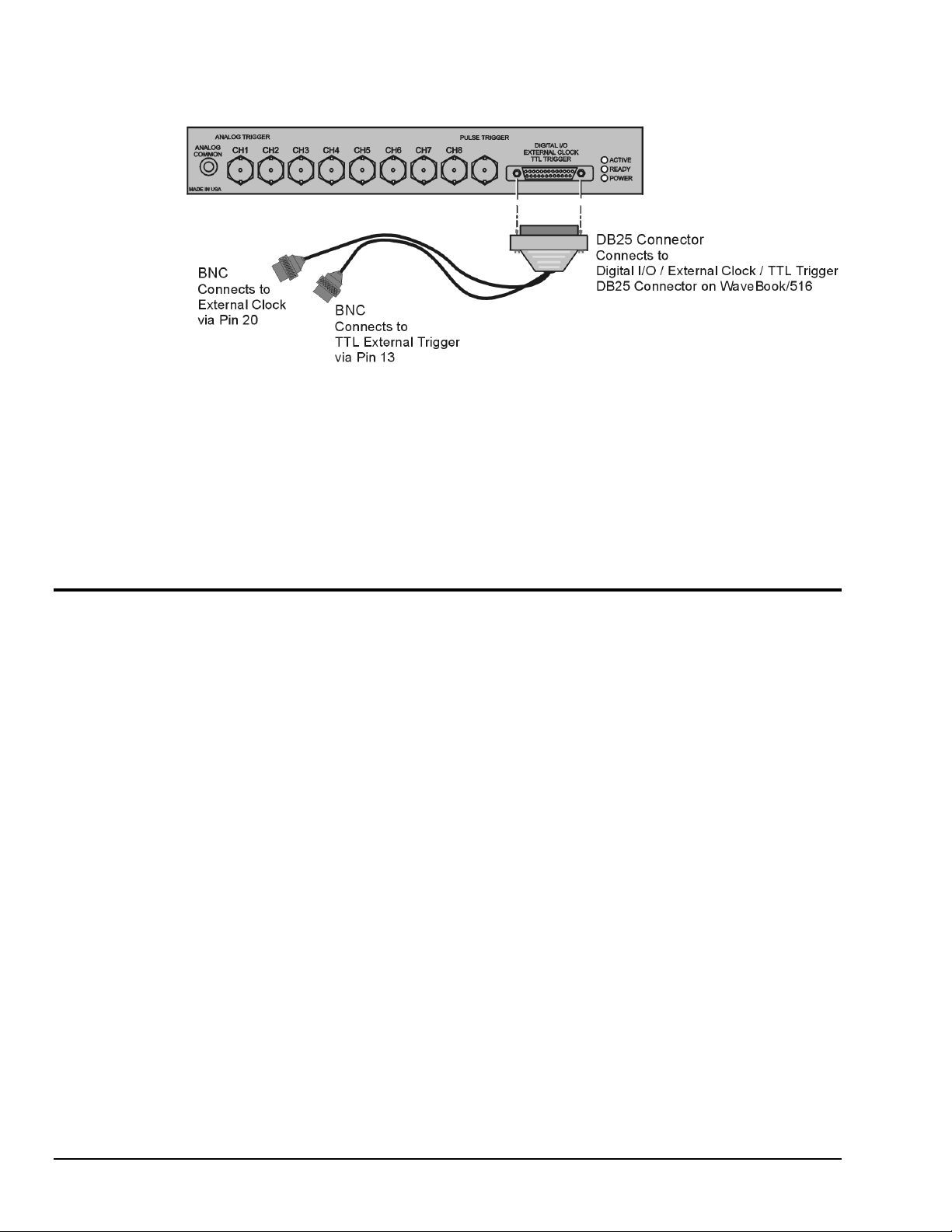
WaveBook/516 with Optional Clock and External Trigger Cable (CA-178)
Pulse Trigger Connection (WaveBook/516 Series Only)
To the right of the 8 BNC connectors for analog inputs, the WaveBook/516 series provides one additional
BNC connector for pulse trigger (see previous figure). This high-bandwidth input enables the triggering
and hence the correlation of lower-speed waveforms with the occurrence of a high-speed anomaly. With
pulse trigger, the user defines a pulse amplitude between +5 and -5 volts, and a pulse width between
100 ns and 800 ms.
System Testing
Windows 95/98/NT WaveBook Configuration
The Daq Configuration applet, designed for 32-bit Windows 95/98/NT systems, is located in the Windows
Control Panel. It allows you to add or remove a device and change configuration settings. The included
test utility provides feedback on the validity of current configuration settings, as well as performance
summaries.
Device Inventory Dialog Box
Run the applet by double-clicking on the Daq Configuration icon in the Windows Control Panel.
The Device Inventory dialog box will open, displaying all currently configured devices. Displayed devices
show their name and an icon to identify the device type. If no devices are currently configured, no devices
will appear in this field.
The four buttons across the bottom of the dialog box are used as follows:
• Properties: Current configuration settings for a device can be changed by first bringing up the
2-6 WaveBook Setup,
corresponding Properties dialog box. Open the Properties dialog box by double-clicking on the device
icon or selecting the device and then clicking on the Properties button.
6-23-99
WaveBook User’s Manual
Page 29
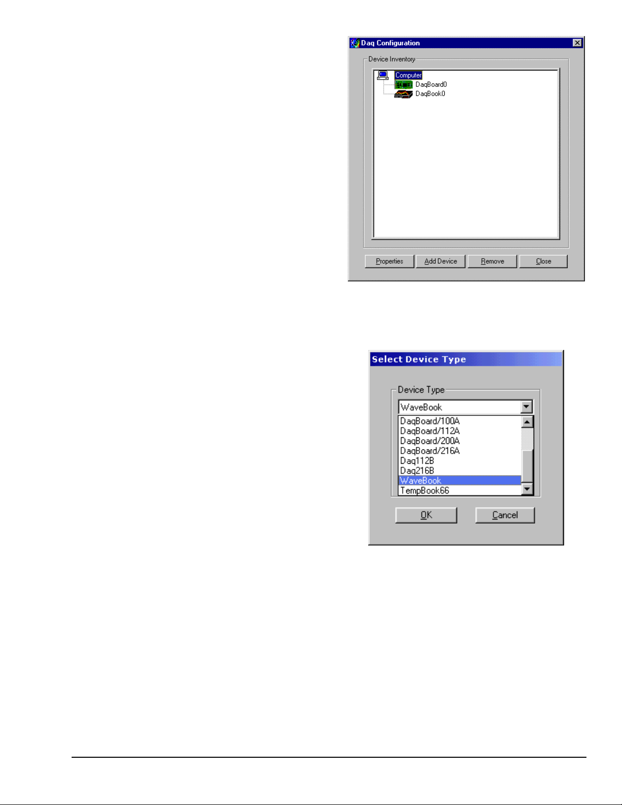
• Add Device: The Add Device button is
used to add a device configuration
whenever a new device is added to the
system. Failure to perform this step will
prevent applications from properly
accessing the device. Clicking on the Add
Device button will open the Select Device
Type dialog box.
• Remove: The Remove button is used to
remove a device from the configuration.
A device may be removed if it is no
longer installed, or if the device
configuration no longer applies.
Note: If a device is removed, applications
may no longer access the device.
However, the device can be
re-configured at any time using the
Add Device function described above.
• Close: The Close button may be used at
any time to exit the Daq Configuration
applet.
Daq Configuration - Device Inventory Dialog Box
Select Device Type Dialog Box
This dialog box opens when the Add Device
button of the Device Inventory dialog box is
selected.
The device type you select for configuring will
appear in the main edit box. Clicking on the
OK button will then open the Properties dialog
box (following figure).
Daq Configuration - Select Device Type Dialog Box
Properties Dialog Box
This dialog box opens when the Properties button of the Device Inventory dialog box is selected, or when
the OK button of the Select Device Type dialog box is selected. It displays the properties for the WaveBook
device with the default configuration settings. The fields include:
WaveBook User’s Manual
6-23-99
WaveBook Setup 2-7
Page 30
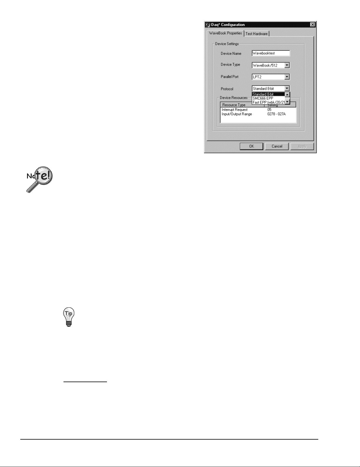
• Device Name: The Device Name field is displayed
with the default device name. As shown, this field
can be changed to any descriptive name as desired.
This device name is the name to be used with the
daqOpen
function to open the device. This name
will also be displayed in the device lists for opening
the device in the WaveView and WaveCal
applications.
• Device Type: The Device Type field indicates the
device type that was initially selected. However, it
can be changed here if necessary.
• Parallel Port: The Parallel Port field is used to set
the parallel port for communicating with the
WaveBook.
• Protocol: The Protocol field is used to set the
parallel port protocol for communicating with the
WaveBook. Depending on your system, not all
protocols may be available. (See following Note).
Daq Configuration - Properties Dialog Box
In regard to Protocol – If you are using a WBK20A or WBK21, you must select
“Fast EPP (wbk/20/21)” to achieve the best performance.
• Device Resources: The Device Resources field lists settings for various resources, among them
Interrupt Request, Input/Output Range, and Direct Memory Access.
• OK: Click on the OK button to store the configuration and exit the current dialog box.
• Cancel: Click on the Cancel button to exit the current dialog box without storing any changes.
• Apply: Click on the Apply button to store the configuration.
Or you can click the following tab:
• Test Hardware: Click on the Test Hardware tab to test the current stored configuration for the device.
This selection will open the Test Hardware dialog box.
Test Hardware Dialog Box
Before testing WaveBook, make sure the device has been properly installed and powered-on. Make sure
the parallel port cable is firmly in place on both the WaveBook and the proper LPT port in the computer.
When testing WaveBook, if the unit does not respond within 30 seconds perform the
following steps:
1) reboot the system
2) upon power-up, re-open the Daq Configuration applet
3) select another configuration setting
4) reinitiate the test
To test the currently stored configuration for the WaveBook device, click the Test button. Results should be
displayed in a few seconds. The test results have two components: Resource Tests and Performance Tests.
Resource Tests. The resource tests are intended to test system capability for the current device
configuration. Resource tests are pass/fail. Test failure may indicate a lack of availability of the resource,
or a possible resource conflict.
2-8 WaveBook Setup,
Base Address Test. This resource test checks the base address for the selected parallel port. Failure of
this test may indicate that the parallel port is not properly configured within the system. See relevant
operating system and computer manufacturer’s documentation to correct the problem.
6-23-99
WaveBook User’s Manual
Page 31

Performance Tests. These types of tests are intended
to check various WaveBook functions, using the current
device configuration. Performance tests provide
quantitative results for each supported functional group.
Test results represent maximum rates the various
operations can be performed. The rates depend on the
selected parallel port protocol, and vary according to
port hardware capabilities.
WBK30 FIFO Test. This performance test checks
the data-storing capabilities of the optional, WBK30
memory card.
Note that the figure to the right represents results
from a previous test. Initially, the screen shows no
test results.
Daq Configuration - Test Hardware Dialog Box
When the test is completed successfully, the Daq Configuration Test Dialog Box indicates a passed
condition. For example, in the above figure: WBK30 FIFO Test ÆÆÆÆ Passed.
These “Passed” messages indicate you can exit the test program and run your application.
WaveBook User’s Manual
6-23-99
WaveBook Setup 2-9
Page 32

2-10 WaveBook Setup,
6-23-99
WaveBook User’s Manual
Page 33

WBK Expansion Options 3
WBK10/10H
Expansion Module (8 channels)
WBK11
Simultaneous Sample & Hold Card (8 channels)
WBK12/13
WBK12: Programmable Low-Pass Filter Card (8 channels)
WBK13: Programmable Low-Pass Filter Card with SSH (8 channels)
WBK14
Dynamic Signal Conditioning Module (8 channels)
WBK15
8-Slot 5B Signal Conditioning Module (8 channels)
WBK16
Strain-Gage Module (8 channels)
WBK30
WaveBook Memory Option, 16 MB, 64 MB, or 128 MB
WBK61/62
WBK61: High-Voltage Adapter with 200:1 Voltage Divider (1 channel)
WBK62: High-Voltage Adapter with 20:1 Voltage Divider (1 channel)
3-2
3-6
3-8
3-10
3-17
3-22
3-45
3-49
You can use various modules and option cards to expand your WaveBook system. Internally, WaveBook has room for
one signal-conditioning card. Externally, you can use one or more WBK10/10H expansion modules. Note that unless
you placed a special order, WaveBook/516 will have a pre-installed PGA card.
Reference Notes:
The following items are not directly related to channel expansion and appear elsewhere in this manual.
• WBK20A – PCMCIA/EPP Interface Card (for linking a WaveBook to a Notebook PC) ……. Page 2-1
• WBK21 – ISA/EPP Interface Card (for linking WaveBook to a Desktop PC) …… page 2-2
• DBK30A – Rechargeable Battery Module …… page 4-4
• DBK34 – Vehicle UPS Module …… page 4-7
•
Power-supply options and setups are discussed in chapter 4, System Power & Assembly.
Using Shielded BNC Connectors (for CE Compliance)
Certain Declarations of Conformity identify specific cables and connectors that must be used to meet
CE requirements. CE compliant BNC-equipped cards and modules have BNC connectors that are insulated
from high voltage sources, including electrostatic discharges (ESD). Such voltages could enter the circuitry
through the exposed conductive surface of a connector, possibly resulting in damage to components.
O-Ring
Shielded
BNC Connector
WaveBook User’s Manual,
ch03A 6-18-99
Dust Cap
Shielded BNC Connector (with O-Ring) and PVC Dust Cap
WBK Expansion Options 3-1
Page 34

To meet CE requirements, PVC dust caps (p/n CN-96) must cover all unused BNC connectors. When dust
caps are not in place, special coaxial cables (with insulated end-connectors and rubber O-rings) must be
used. Note that part number 418-0800 includes two cables (with shielded BNC connectors at each end),
and four insulating O-rings.
Properly installed connectors and dust caps ensure the metallic surfaces of the connectors are not exposed to
undesirable electrical charges.
WBK10/10H - Expansion Modules
Description
The WBK10/10H expansion modules provide the WaveBook with 8 additional differential analog inputs,
each equipped with a programmable gain instrumentation amplifier (PGA). (The two models are the same
except for analog input ranges.) The WaveBook and WBK10/10H have a built-in expansion bus. Up to
eight WBK10/10Hs can be cascaded together for a system capacity of 72 differential channels. Each
WBK10/10H is also capable of supporting a WBK11, WBK12, or WBK13 option card.
Physically, the WBK10/10H is the same size (8½×11 in) as the WaveBook for convenient mounting. A
splice plate kit allows multiple units to be stacked vertically. Screw-on handles are available for portable
applications.
J10
Optional
WBK11
J11
Channel 1 of 8
8
Differential
Analo g
Inputs
DIN5s can be
dais y-ch ained
N
Buffers
10 to 30 VDC Input power
from AC adapter, DBK30A,
DBK34, or 12-V car battery, etc
Fuse
Converter
Power Supply
DC/DC
ON/OFF
Switch
+5
- 5
+15
- 15
7
7
8-channel
Differential
MUX
Offset Adjust
Differential
Amplifier
WBK10 Block Diagram
+
-
PGA
Unipolar/Bipolar
Level Shifter
EEPROM
Front & Rear Panels
The front panel of the WBK10/10H has the following connectors and indicators:
• 1 Analog Common binding post for reference.
•
8 BNC connectors for analog inputs. Channels are labeled 1 through 8. Note that additional WBK10/10H unit
channels are identified by higher channel numbers as discussed in upcoming text.
•
3 Status LEDs (Active, Ready, Power).
Control and
Timing Circuit
Enable
N
Expansion
Signal
N
IN
Expansion
Unit Control
OUT
The rear panel of the WBK10/10H has a power switch and the following connectors:
• 2 circular 5-pin DIN5 connectors for Power-in and Power Pass-Through.
• 1 HD-15M expansion control input.
• 1 HD-15F expansion control output.
•
2 BNC connectors for analog expansion, in and out.
3-2 WBK10/10H, W BK Expansion Options WaveBook User’s Manual
Page 35

Hardware SetupConfiguration
The analog input channel numbers are determined by the order of connection
among the WaveBook and attached WBK10/10H units.
• Channel 0 is the WaveBook’s 8-bit digital I/O port.
•
Channels 1 through 8 are the WaveBook’s main channels.
•
Channels 9 through 16 are located on the first expansion unit connected
directly to the WaveBook.
• Additional channel numbers (in groups of 8) are added consecutively with
added WBK10/10Hs (see table).
Power, Expansion Control, and Expansion Signal Connections
WBK expansion modules can be configured in various ways, such as:
• A WBK10/10H connects to a WaveBook or to another WBK10/10H.
• A lone WBK10/10H in the system connects directly to the WaveBook.
•
An add-on WBK10/10H connects to the previous WBK10/10H in a daisy-chain fashion.
• Other WBK expansion modules are connected in a similar way.
You must make connections for power, expansion control, and expansion signals. A system using three
WBK10 modules (daisy-chained to a WaveBook) is depicted in the following figure.
Unit Channel #
WaveBook 0 (dig I/O)
WaveBook 1-8
1st WBK10 9-16
2nd WBK10 17-24
3rd WBK10 25-32
4th WBK10 33-40
5th WBK10 41-48
6th WBK10 49-56
7th WBK10 57-64
8th WBK10 65-72
WaveBook User’s Manual,
Example of WaveBook and WBK10 Daisy-Chain
s
CAUTION
CAUTION
CAUTIONCAUTION
Do not daisy-chain the power connections of more than three WBK10/10H units.
Daisy-chaining a power connection to a fourth module will exceed the power connector
5 amp current limit.
CA-115 Power Cables. CA-115 cables are 6 inches long and have two 5-pin male DIN connectors.
CA-115s are frequently used to link WaveBook’s power out to a WBK10/10H module’s power in
connector. CA-115 cables are also commonly used to link WBK10/10H power out connectors to
the next daisy-chained module’s power in. See previous figure.
ch03A 6-18-99
WBK Expansion Options 3-3
Page 36

Reference Note: More power-related information can be obtained from the Power Connection
text, below, and from chapter 4, System Power & Assembly.
CA-129 Expansion Control Cables. Control messages are carried by CA-129 expansion-control
cables (HD-15, plug and socket connectors). The first expansion unit’s control input is driven from
the main unit’s control output. Control inputs of additional WBK10/10Hs are driven from the
preceding unit’s control output.
CA-150 Expansion Signal Cables. Expansion signals are carried by a CA-150-1 male BNC to
male BNC coaxial cable. Each WBK10/10H drives a common parallel analog bus that carries the
signals to the ADC in the WaveBook. Each WBK10/10H has input and output connectors for
daisy-chaining multiple units.
Power Connections
Reference Note: More power-related information can be obtained from chapter 4,
System Power & Assembly. CA-115 cables are discussed in preceding text.
10 to 30 VDC power can be supplied to a WBK10/10H unit through its POWER IN DIN5 connector in any
of the following ways.
• Separate power supplies. Each WBK10/10H can have its own, separate power supply. In other words,
the power set-up does not need to be dasiy-chained. Note that each WBK10/10H is shipped with a
power adapter.
• Single power supply. A single power supply can be used to power several WBK10/10H units.
An optional TR-40U power adapter can power several WBK10/10Hs when the units are daisy-chained
with CA-115 power cables (preceding figure). The number of WBK10/10Hs is limited to the amount
of power available and the amount of power used by option cards. As stated in the earlier caution, do
not daisy-chain the power for more than three WBK10/10H units.
• DBK30A Rechargeable Battery Module. The DBK30A can provide battery power for portable
applications via a CA-115 power cable. DBK30A is detailed in chapter 4,beginning on page 4-3.
DBK30A Rechargeable Battery Module
• DBK34 Vehicle UPS Module. The DBK34 can provide back-up battery power as an uninterruptible
power supply (UPS) for portable applications via the CA-115 power cable. DBK34 is detailed in
chapter 4, beginning on page 4-6.
DBK34 Vehicle UPS Module
• CA-116 cable. A car battery can be used for power when connection is made via the optional CA-116
cable. The CA-116 is a 5-pin DIN to automotive cigarette lighter power cable.
3-4 WBK10/10H, W BK Expansion Options WaveBook User’s Manual
Page 37

Assembly
The WBK10/10H base dimension is the same as WaveBook’s. This allows for convenient stacking, since
horizontal and depth requirements remain unchanged. A fastener panel is used to stack the units. Screw-on
handles are available for portable applications. For detailed assembly information, see chapter 4: System
Power & Assembly.
Software Setup
You will need to set several parameters so WaveView can best meet your application requirements. For
software setup information, refer to the "Software Setup" section in Chapter 2: WaveBook Setup. For
detailed WaveView information, refer to Chapter 5: WaveView.
WBK10/10H - Specifications
Specifications are provided in Appendix A.
WaveBook User’s Manual,
ch03A 6-18-99
WBK Expansion Options 3-5
Page 38

WBK11 - Simultaneous Sample & Hold Card
Description
WBK11 is a simultaneous sample-and-hold card (SSH) that can be installed in the field. The card can
simultaneously sample 8 channels. WBK11 can be installed inside a WaveBook or a WBK10/10H and is
controlled by the WaveBook. WBK11 allows concurrent (<150 ns) capture of multiple input channels and
virtually eliminates channel-to-channel time skewing.
When using WaveBook with an SSH channel enabled, the per-channel sample rates are
reduced. The rate reduction is the same as that which would occur if another channel
were added. The per-channel rate (with SSH enabled) is:
1 MHz / (n+1), where n is the number of active channels.
The WBK11 SSH card can accommodate higher gains than the main unit because its gains are fixed for
each channel prior to the acquisition. Each channel may be set, in software for ranges shown in the table.
All channels equipped with SSH circuitry are sampled simultaneously as a system.
The figure shows a block diagram of the WBK11. All connections are through P10 and P11.
Hardware Setup
Configuration
All WBK11 configurations are controlled by software. There are no hardware settings.
Installation
The WBK11 connects to headers J10 and J11 in the base unit. The base unit can be a WaveBook/512,
/512H, WaveBook/516, or WBK10/10H. The jumpers located on J10 and J11 provide signal pass-through
when the WBK11 is not installed. Use the following steps to install the WBK11 into a WaveBook, or
WBK10/10H module.
P10
mates
with
WaveBook
J10
One of 8 Channel s (Typical)
Offset Adjust
Diff. Amp.
Octal
DAC
+
PGA
-
SCI - Serial
Configuration Interface
Sample/
Hold
MUX
Buffer
Amplifier
P11
mates
with
WaveBook
J11
WBK11 Block Diagram
Although the next figure represents installation of a WBK11 into a WaveBook/512,
installation into other WaveBooks (and WBK10/10H) are similar. Note that the
following steps should be used when installing WBK11, WBK12, or WBK13.
1. Remove all power from the unit and any connected devices.
For WaveBook/512 series only, remove the screw holding down the top panel (cover), and slide the
2.
panel out towards the back.
For WaveBook/516 only, remove four side screws and lift the cover free of the chassis.
Remove present board from J10 and J11. If no board is installed in J10 and J11, skip to step 4.
3.
If a board is already installed:
(a) remove that board’s stand-off screws
(b) remove the board
Note: Unless a special order has been placed, WaveBook/516 series is shipped with a PGA card
installed.
3-6 WBK14, WBK Expansion Options WaveBook User’s Manual
Page 39
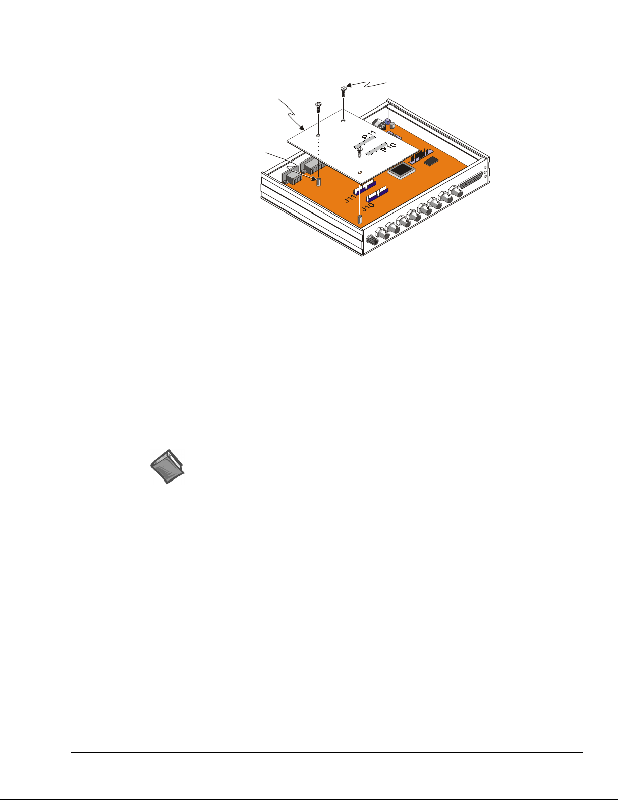
4. Locate the headers J10 & J11 on the main board, and remove the jumpers (if present).
Save the jumpers in the event the SSH board needs to be removed.
WBK11 Board.
P11 connects to J11,
and P10 connect s to J10.
Standoff (×3)
WBK11 Connection to WaveBook
Use 3 screws to secure
the WBK11 to the standoffs.
5. Align WBK11 headers (P11 & P10) with the host board headers (J11 & J10), respectively.
6. Verify alignment of the board. An easy way is to check that the board’s screw holes are in line with the
standoffs.
7. Carefully push the WBK11 down until the connectors fully mate.
8. Using three screws, secure the WBK11 to the standoffs. Do not over-tighten.
9. Slide the top panel onto the unit, and secure it using the top panel screw.
10. Power up the unit.
11. Run WaveView to verify the channels connected to WBK11 have the new ranges.
Software Setup
You will need to set several parameters so WaveView can best meet your application requirements. For
software setup information, refer to the "Software Setup" section in Chapter 2: WaveBook Setup. For
detailed WaveView information, refer to Chapter 5: WaveView.
Reference Note: For more software setup information, refer to the "Software Setup"
section in chapter 2. For detailed WaveView information, refer to chapter 5.
WBK11 - Specifications
Specifications are provided in Appendix A.
WaveBook User’s Manual WBK Expansion Options, WBK14 3-7
Page 40

WBK12/13 - Programmable Low-Pass Filter Cards
Description
The WBK12 and WBK13 are 8-channel programmable low-pass filter cards for use with 1-MHz
WaveBook data acquisition system. These cards install directly into the WaveBook or WBK10/10H
expansion module and provide programmable low-pass filtering over all channels. Multiple WBK12 and
WBK13 cards can be installed in one system for up to 72 channels. All of the cards’ low-pass filters and
cutoff frequencies are configured via software. The WBK13 has the additional capability of simultaneous
sampling all channels. If multiple WBK13 cards are installed within one system, all channels are sampled
within 100 ns of each other.
Features of the WBK12 and WBK13 include:
• Low-Pass Filters. Each card provides 8 input channels, arranged in two 4-channel banks; the filter and
cutoff frequency configurations are applied per bank. The cards’ filters can be configured as either an
8-pole elliptic filter with cutoff frequencies of 400 Hz to 100 kHz, or an 8-pole linear-phase filter with
400 Hz to 50 kHz cutoff frequencies.
• Cutoff Frequencies. The WBK12 and WBK13 provide 747 discrete cutoff frequencies that can be
determined exactly by the formula Fc = 300 kHz/N; where the integer N = 3 to 750. Alternatively, you
can configure any channel to bypass the programmable filter entirely, resulting in a 1-pole low-pass
filter at about 500 kHz.
• Programmable-Gain Amplifiers. The cards’ programmable-gain instrumentation amplifiers can be
software selected to various gains on a per channel basis. The gains are set prior to the beginning of an
acquisition sequence and cannot be changed during an acquisition. Note that WBK12/13 gain
specifications are provided in Appendix A.
• Simultaneous Sample-and-Hold (SSH) (WBK13 only). In addition to the filtering capability of the
Hardware Setup
Configuration
WBK12, the WBK13 also provides per channel SSH. Simultaneous sampling of all channels occurs at
the start of a scan sequence.
When using WaveBook with an SSH channel enabled, the per-channel sample rates are
reduced. The rate reduction is the same as that which would occur if another channel
were added. The per-channel rate (with SSH enabled) is:
1 MHz / (n+1), where n is the number of active channels.
P10
mates
with
WaveBook
J10
One of 8 Channel s (Typical)
Offset Adjust
Diff. Amp.
Octal
DAC
+
PGA
-
SCI - Serial
Configuration
Interface
Anti-Al ias
LP Filter
WBK12 & WBK13 Block Diagram
Switched
Cap Filter
Dual
Divide-by-N
Sample/
Hold
(WBK13)
S/H
20 MHz
Clock
MUX
Buffer
Amplifier
P11
mates
with
WaveBook
J11
The WBK12 and WBK13 configurations are controlled by software. No hardware settings are required.
Installation
WBK12 and WBK13 connect to WaveBook, or WBK10/10H the same way as the WBK11.
To install, use the same steps provided for the WBK11, on page 3-6.
3-8 WBK14, WBK Expansion Options WaveBook User’s Manual
Page 41

Software Setup
You will need to set several parameters so WaveView can best meet your application requirements. For
software setup information, refer to the "Software Setup" section in Chapter 2: WaveBook Setup. For
detailed WaveView information, refer to Chapter 5: WaveView.
Reference Note: For more software setup information, refer to the "Software Setup"
section in chapter 2. For detailed WaveView information, refer to chapter 5.
WBK12/13 - Specifications
Specifications are provided in Appendix A.
WaveBook User’s Manual WBK Expansion Options, WBK14 3-9
Page 42

WBK14 - Dynamic Signal Input Module
Description
The WBK14 is a dynamic analog signal input module for the WaveBook data acquisition system. The
WBK14 provides a complete system to interface to piezoelectric transducers that include accelerometers,
microphones, force/pressure transducers, and others.
Reference Note: An accelerometer tutorial begins on page 3-13.
Each WBK14 channel has a:
•
current source for transducer biasing
•
high-pass filter
• programmable gain amplifier
•
anti-aliasing low-pass filter
•
simultaneous sample-and-hold (SSH) amplifiers
The gain, filter cut-off frequencies and current biasing levels are software programmable.
WBK14 includes a built-in programmable excitation source. This source stimulates dynamic systems for
transfer function measurements, and serves as a reference signal for calibration.
One of 8 channels
Transducer Bias
N
Current Source
10 Hz
High-Pass
Filter
0.1 Hz
High-Pass
Filter
MUX
+
PGA
-
Channel
Input
BNC
Programmable
Low-Pass Filter
Phase Equalizer
MUX
Programmable
Anti-aliasing
Low-Pass Filter
Sample
& Hold
Buffer
Multiplexed
Analog Output
to WaveBook
MUX
Expansion
Signal
BNC
N
N
10 to 30 VDC Input power
from AC adapter, DBK30A,
DBK34, or 12-V car ba ttery, etc
Power Supply
+5
- 5
+15
- 15
DC/DC
Converter
Fuse
ON/OFF
Switch
DIN5s can be
daisy-chaine d
Externa l
Clock
Excitation
Source
Output
BNC
BNC
N
OSC
N
Timebase
Control
Amplitude
DAC
Offset
DAC
PLL
Filter
Control Logic
EEPROM
µP and
IN
Expansion
Unit Control
OUT
WBK14 Block Diagram
Current Source
WBK14 provides constant current to bias ICP transducers. Two current levels (2 mA or 4 mA) with
voltage compliance of 27 V can be selected via software. The bias current is sourced through the center
conductor of a coaxial lead and returns to the WBK14 by the outer conductor. The output impedance is
larger than 1 MΩ and presents virtually no loading effect on the transducer’s output. For applications that
do not require bias, the current source can be removed from the BNC input by opening a relay contact.
The current sources are applied to (or removed from) the input in channel groups of two; i.e.,
channels 1-2, 3-4, 5-6, 7-8.
3-10 WBK14, WBK Expansion Options WaveBook User’s Manual
Page 43

High-Pass Filter (HPF)
Each WBK14 channel has two independent High-Pass Filters (HPFs) with a 3-dB cut-off frequency (Fc) at
0.1 Hz and 10 Hz. The 0.1-Hz HPF is a single-pole RC filter, and is primarily used to couple vibration
signals. The 10-Hz HPF is a 2-pole Butterworth type and can be used to couple acoustic signals or attenuate
setup-induced low-frequency signals that can reduce the dynamic range of the measurement (for example
when using tape recorders as signal sources).
Programmable Gain Amplifier (PGA)
The HPF removes the DC voltage from the input signal. A PGA amplifies the AC voltage with flat response
up to 500 kHz. Each channel has a PGA with 8 programmable gains (1, 2, 5, 10, 20, 50, 100, and 200) and
a software-controlled DAC for offset nulling. The WBK14 measures only bipolar signals up to 5 V peak.
Programmable Low-Pass Filter Phase Equalizer
The first filter stage is a programmable 2-pole continuous-time low-pass filter. The phase equalizer provides
more than 65 dB alias protection to the next filter stage. In addition, it fine-tunes the phase shift of the
channel to optimize the phase-matching between channels. At calibration, the phase shift of each channel is
measured and stored in an EEPROM that is read at configuration.
Programmable Low-Pass Anti-Aliasing Filter
Most of the signal alias rejection is performed by an 8-pole Butterworth filter. This filter is implemented
with a switch-capacitor network driven by a programmable clock. Each channel has an independent clock
whose frequency determines the 3-dB cut-off frequency of the filter. The switch-capacitor filter provides no
attenuation at the clock frequency—hence, the need for the continuous-time low-pass filter.
Note: The Low-Pass Anti-Aliasing Filter can be bypassed to process signals with a bandwidth higher
than 100 kHz.
The EXT.CLK input provides a path to externally control the cut-off frequency of the Low-Pass
Anti-Aliasing Filter. The input waveform can be TTL or sinusoidal, with an amplitude peak of at least
500 mV. In this mode, the cut-off frequency is set to the input frequency divided by 50.
Simultaneous Sample and Hold
All WBK14 channels are sampled simultaneously, after which the WaveBook measures each output at
1 µs/channel until all channels are digitized. The time-skew between sampling on all channels (up to 72)
is 150 ns, regardless of the number of WBK14s attached to the WaveBook.
When using WaveBook with an SSH channel enabled, the per-channel sample rates are
reduced. The rate reduction is the same as that which would occur if another channel
were added. The per-channel rate (with SSH enabled) is:
1 MHz / (n+1), where n is the number of active channels.
Excitation Source
The excitation source includes a sine/random waveform generator, a programmable gain amplifier (PGA), a
DC-level DAC, and a phase-lock loop (PLL). The PLL is used to synthesize the frequency of a fixedamplitude sine wave and control the bandwidth of the random signals. The PGA conditions the signal
amplitude to a value between 0 V to 5 V peak. The DC level of the signal is varied independently of signal
amplitude by a software-controlled DAC from -5 V to +5 V. The DC level of the excitation signal can be
used to balance static loads, while the AC signal provides the dynamic excitation.
Calibration
WBK14 is calibrated digitally, eliminating the need for all potentiometers and manual adjustments.
WaveCal, a provided Windows-based program, simplifies the calibration process.
WaveBook User’s Manual WBK Expansion Options, WBK14 3-11
Page 44

Hardware Setup
Configuration
All WBK14 configurations are controlled by software. The WBK14 requires no hardware settings.
Installation
The WBK14 connects to WaveBook, or WBK10/10H the same way as a WBK10/10H module connects.
To install, use the same steps provided for the WBK10/10, on page 3-3.
Power
Like the WaveBook, the WBK14 contains an internal power supply. The unit can be powered by an
included AC power adapter or from any 10 to 30 VDC source, such as a 12 V car battery. For portable or
field applications, the WBK14 and the WaveBook can be powered by the DBK30A rechargeable battery
module or the DBK34 uninterruptible power supply (UPS) module.
CAUTION
CAUTION
CAUTIONCAUTION
If the following two conditions exist simultaneously:
• operating WBK14s in a configuration of 4 or more modules
• ambient temperature >40°C;
then you must mount the modules on their side (vertically) to facilitate air flow
through the side plates. Failure to due so could result in thermal-related problems.
You must compute power consumption for your entire system and (if necessary) use
auxiliary or high-current power supplies.
Assembly
Physically, the WBK14 is the same size as the WaveBook for convenient mounting. A fastener panel allows
multiple units to be stacked vertically. Screw-on handles are available for portable applications. For more
assembly information, see chapter 4: System Power & Assembly.
Software Setup
Depending on your application, you will need to set several software parameters. Proper settings will allow
WaveView to organize data to meet your requirements. The next figure shows the WaveView Configuration
main window. Some items of importance to the WBK14 are the Module Configuration window and the
low-pass and high-pass filter options, as follows:
The Module Configuration window allows you to set the following Excitation Source parameters:
amplitude, offset, waveform, and frequency.
In the WaveView Configuration main window:
Reference Note:
For more WaveBook power information, see chapter 4: System Power & Assembly.
LPF On – Turns On the Low-Pass Filter, Bypasses the LPF, or selects an External Source.
LPF Cutoff – Sets th Low-Pass Filter cutoff frequency.
LPF Type – Sets the type of Low-Pass Filter.
Reference Note:
For more software setup information, refer to the “Software Setup” in chapter 2. For
detailed WaveView information, refer to chapter 5.
3-12 WBK14, WBK Expansion Options WaveBook User’s Manual
Page 45

Accelerometer Tutorial
A low-impedance piezoelectric accelerometer consists of a piezoelectric crystal and an electronic amplifier.
When stretched or compressed, the two crystal surfaces develop a charge variation that is related to the
amount of stress, shock, or vibration on the crystal. The amplifier outputs a corresponding signal and
transforms the sensor’s high impedance to a lower output impedance of a few hundred ohms. Besides
acceleration, such sensors can measure pressure and force.
The circuit requires only 2 wires (coax or twisted pair) to transmit both power and signal. At low
impedance, the system is insensitive to external or “triboelectric” cable noise. Cable length does not affect
sensitivity.
The figure shows a simple sensor-WBK14 connection. The voltage developed across R is applied to the
gate of the MOSFET. The MOSFET is powered from a constant current source of 2 or 4 mA and 27 volts.
WaveView and Module Configuration Windows
Sensor to WBK14
Coaxial Cable
MOSFET
-
Bias
Vol ta ge
Sensor
R
Accelerometer Circuit
Crystal
WaveBook User’s Manual WBK Expansion Options, WBK14 3-13
+
30 VDC
Power
C
Constant
Current
(2 or 4 mA)
WBK14
Amplifier
Input
GND
Page 46

The MOSFET circuit will bias off at approximately 12 V in the quiet state. As the system is excited, voltage
is developed across the crystal and applied to the gate of the MOSFET. This voltage will cause linear
variation in the impedance of the MOSFET and a proportional change in bias voltage. This voltage change
will be coupled to the WBK14 input amplifier through the capacitor C. The value of R and the internal
capacitance of the piezoelectric crystal control the low frequency corner. Units weighing only a few grams
can provide high level outputs up to 1 V/g with response to frequencies below 1 Hz.
Accelerometer Specification Parameters
Noise in Accelerometers. The noise floor or resolution specifies lowest discernible amplitude
(minimum “g”) that can be measured. There are two main sources of noise as follows:
• Noise from the crystal and microcircuit inside the accelerometer. Some types of crystals, such as
quartz, are inherently more noisy than others. A good noise floor is 10 to 20 µV.
• Noise from electrical activity on the mounting surface. Since the signal from the accelerometer is a
voltage, 60 Hz or other voltages (ground loop, etc) can interfere with the signal. The best protection is
to electrically isolate the accelerometer.
Sensitivity. The sensitivity of an accelerometer is defined as its output voltage per unit input of motion. The
unit of motion used is “g.” One “g” is equal to the gravitational acceleration at the Earth’s surface, which is
32.2 ft/(sec)(sec) or 981 cm/(sec)(sec). The output is usually specified in millivolts per “g” (mV/g).
Sensitivity is usually specified under defined conditions such as frequency, testing levels, and temperature.
An example: 100 mV/g at a frequency of 100 Hz, level +1 g, at 72°F. Note that, although a sensor may
have a “typical” sensitivity of 100 mV/g, its actual sensitivity could range from 95 to 105 mV/g (when
checked under stated conditions). Manufacturers usually provide sensor calibration values.
Transverse Sensitivity. An accelerometer is designed to have one major axis of sensitivity, usually
perpendicular to the base and co-linear with its major cylindrical axis. The output caused by the motion
perpendicular to the sensing axis is called transverse sensitivity. This value varies with angle and frequency
and typically is less than 5% of the basic sensitivity.
Base-Strain Sensitivity. An accelerometer’s base-strain sensitivity is the output caused by a deformation of
the base, due to bending in the mounting structure. In measurements on large structures with low natural
frequencies, significant bending may occur. Units with low base-strain sensitivity should be selected.
Inserting a washer (smaller in diameter than the accelerometer base) under the base reduces contact surface
area; and can substantially reduce the effects of base-strain. Note that this technique lowers the usable
upper frequency range.
Acoustic Sensitivity. High-level acoustic noise can induce outputs unrelated to vibration input. In general,
the effect diminishes as the accelerometer mass increases. Use of a light, foam-rubber boot may reduce this
effect.
Frequency Response. An accelerometer’s frequency response is the ratio of the sensitivity measured at
frequency (f) to the basic sensitivity measured at 100 Hz. This response is usually obtained at a constant
acceleration level, typically 1 g or 10 g. Convention defines the usable range of an accelerometer as the
frequency band in which the sensitivity remains within 5% of the basic sensitivity. Measurements can be
made outside these limits if corrections are applied. Care should be taken at higher frequencies because
mounting conditions greatly affect the frequency range (see Mounting Effects, in upcoming text).
Dynamic Range. The dynamic measurement range is the ratio of the maximum signal (for a given distortion
level) to the minimum detectable signal (for a given signal-to-noise ratio). The dynamic range is determined
by several factors such as sensitivity, bias voltage level, power supply voltage, and noise floor.
Bias Level. Under normal operation, a bias voltage appears from the output signal lead to ground. There are
two basic MOSFET configurations commonly used. One exhibits a 7-8 V bias and the second a 9-12 V
bias. Operation of the two circuits is identical except for the available signal swing. The low-voltage version
typically exhibits 5-10 µVrms versus 10-20 µVrms for the high voltage.
3-14 WBK14, WBK Expansion Options WaveBook User’s Manual
Page 47

Thermal Shock - Temperature Transients. Piezoelectric accelerometers exhibit a transient output that is a
function of a temperature’s “rate-of-change.” This “thermal shock” is usually expressed in g/°C and is
related to:
•
Non-uniform mechanical stresses set up in the accelerometer structure.
• A pyroelectric effect in piezoelectric materials—an electrical charge is produced by the
temperature gradient across the crystal.
This quasi-static effect produces a low-frequency voltage input to the MOSFET amplifier. This voltage is
usually well below the low-frequency corner, but the effect can reduce the peak clipping level and cause
loss of data. This effect does not affect the accelerometer’s basic sensitivity or the data unless the thermal
shift in the operation bias level results in clipping. Where drastic thermal shifts are expected, use 12 V bias
models. The effect’s severity is related to the mass of the accelerometer. In 100 mV/g industrial units, the
effect is usually negligible. Using rubber thermal boots can reduce the effect significantly.
Overload Recovery. Recovery time from clipping due to over-ranging is typically less than 1 ms.
Recoveries from quasi-static overloads that generate high DC bias shifts are controlled by the accelerometer
input RC time constant that is fixed during manufacture.
Power Supply Effects. The nominal power supply voltage recommended by most manufacturers is 15 to
24 V. Units may be used with voltages up to 28 volts. Sensitivity variations caused by voltage change is
typically 0.05%/volt. Power supply ripple should be less than 1 mVrms.
Connector. This parameter specifies the connector type and size (4-48, 6-40, 10-32 coaxial etc) and the
location on the sensor, that is, top or side (usually on the hex base). Where there is no connector on the
sensor, an integral cable is specified with the length and the connector, that is, integral 6-ft to 10-32.
Electrical Grounding
Case-Grounded Design. In case-grounded designs, the common lead on the internal impedance matching
electronics is tied to the accelerometer case. The accelerometer base/stud assembly forms the signal
common and electrically connects to the shell of the output connector. Case-grounded accelerometers are
connected electrically to any conductive surface on which they are mounted. When these units are used,
take care to avoid errors due to ground noise.
Isolated-Base Design. To prevent ground noise error many accelerometers have base-isolated design. The
outer case/base of the accelerometer is isolated electrically off ground by means of an isolation stud insert.
The proprietary material used to form the isolation provides strength and stiffness to preserve highfrequency performance.
Cable Driving
Operation over long cables is a concern with all types of sensors. Concerns involve cost, frequency
response, noise, ground loops, and distortion caused by insufficient current available to drive the cable
capacitance.
The cost of long cables can be reduced by coupling a short (1 m) adapter cable from the accelerometer to a
long low-cost cable like RG-58U or RG-62U with BNC connectors. Since cable failure tends to occur at the
accelerometer connection where the vibration is the greatest, only the short adapter cable would need
replacement.
Capacitive loading in long cables acts like a low-pass, second-order filter and can attenuate or amplify highfrequency signals depending on the output impedance of the accelerometer electronics. Generally this is not
a problem with low-frequency vibration (10 Hz to 2000 Hz). For measurements above 2000 Hz and cables
longer than 100 ft, the possibility of high-frequency amplification or attenuation should be considered.
The WBK14 constant-current source provides 2 or 4 mA to integral electronics. Use the higher current
setting for long cables, high peak voltages, and high signal frequencies.
The maximum frequency that can be transmitted over a given length of cable is a function of both the cable
capacitance and the ratio of the maximum peak signal voltage to the current available from the constant
current source:
WaveBook User’s Manual WBK Expansion Options, WBK14 3-15
Page 48

f
K
V
C
2
π
Icc Ib=−
WBK14 - Specifications
Specifications are provided in Appendix A.
Drive Current
(mA)
2 10 185 kHz 37 kHz
2 100 18.5 kHz 3.7 kHz
2 1000 1.85 kHz 370 Hz
4 10 550 kHz 110 kHz
4 100 55 kHz 11 kHz
4 1000 5.5 kHz 1.1 kHz
Where:
f = Maximum frequency in Hz
K = 3.45 ×10
and a factor to allow cable capacitance to charge to 95% of the final charge.
C = Cable capacitance in picoFarads
V = Maximum peak measured voltage from sensor in volts
Icc = Constant current from current source in mA
Ib = Current required to bias the internal electronics, typically 1 mA
9
. K is the scale factor to convert Farads to picoFarads and Amperes to milliAmperes
Cable Length
@30 pF/ft (Ft)
Frequency Response to 5% of
Maximum Output Signal Amplitude
± 1 V ± 5 V
3-16 WBK14, WBK Expansion Options WaveBook User’s Manual
Page 49

WBK15 - 5B Isolated Signal-Conditioning Module
Description
The WBK15 module can accommodate eight 5B isolated-input signal-conditioning modules for use with the
WaveBook. The WaveBook can accommodate 8 WBK15s for a maximum of 64 expansion channels. The
WaveBook scans WBK15’s channels at the same 1 µs/channel rate that it scans all WBK analog inputs,
allowing it to measure all channels of a fully configured 72-channel system in 72 µs.
Other features of WBK15 include:
• Built-in power supply that operates from 10 to 30 VDC and can power a full complement of 5B
modules (even with bridge excitation).
• Removable, plug-in screw-terminal blocks for convenient connection of 5B modules (each block has 4
terminals per channel for input and excitation-output features).
• On-board cold-junction sensing for thermocouple 5B modules.
• For each 5B module, 1500 V isolation from the system and from other channels.
The following figure shows a WBK15 block diagram.
Current-Sense
Resistor
5.000 V
Buffered
5B
Low-
Module
Pass
Socket
Filter
#1
Input
Terminal
Block
Channel 1
Channels 2-8 identical
DC Power
Input &
Expansion
+V
Cold
Junction
Sensor
GND
DIN-5
Power
Switch
CH1
CH2
CH3
CH4
CH5
CH6
CH7
CH8
+15 V
Filters
Isolated
+5, ±15 VDC
Power
Supply
Channel
Selection
MUX
Internal Jumpers
-15 V
+5 V
WBK15 Block Diagram
Reference
Bipolar
Offset
Amp
Buffer
Amp
Control
DAC
µP &
Control Logic
EEPROM
Output
MUX
Status
LEDs
BNC
N
N
Analog
Output to
Wave Book
Expansion
Control
From
WaveBo ok
Hardware Setup
Configuration
The next figure shows the board layout within a WBK15. Note the channel-number layout for the 5B
modules and the location for plug-in current-sense resistors.
WaveBook User’s Manual,
ch03B 6-23-99
Only current-input type modules require the plug-in resistors.
The plug-in resistors must be removed for all other module types.
WBK Expansion Options, WBK15 3-17
Page 50
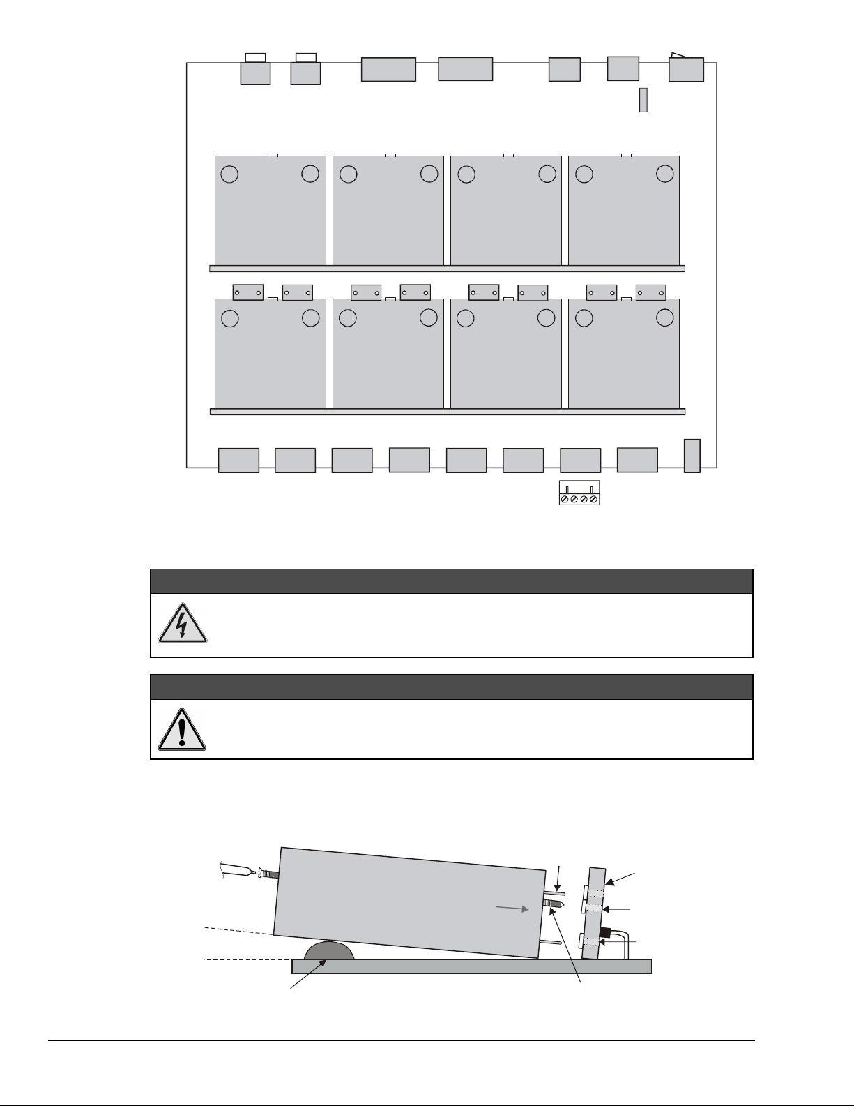
Rear Panel
BNC
Expansion
Signal Out
BNC
Expansion
Signal In
DB15
Expansion
Control Out
DB15
Expansion
Control In
DIN5
Power
Out
DIN5
Power
In
ON/OFF
Switch
Fuse
CHANNEL 1
R10
ch 2
CHANNEL 2 CHANNEL 4
ch 1
Front Panel - signal inputs from 8 channels
R5
ch 2
Installation of 5B Modules
ch 1
CHANNEL 3
R16 R13
ch 4
ch 3
CHANNEL 5
R20
ch 6
ch 3
CHANNEL 6
ch 4 ch 5 ch 6
WBK15 Board Layout
WARNING
WARNING
WARNINGWARNING
R18
ch 5
ch 8
ch 7
CHANNEL 7
R22
CHANNEL 8
ch 8
Screw-terminal
Signal Plug
R23
ch 7
Status
LEDs
Electric shock hazard! Turn off power to WBK15 and all connected modules and
devices before inserting or removing modules. Failure to do so could lead to injury or
death due to electric shock.
CAUTION
CAUTION
CAUTIONCAUTION
Handle the 5B module carefully while inserting pins into the daughterboard. Do not
over-tighten mounting screw.
The 5B modules plug into a daughterboard (×2) on WBK15’s motherboard. Rubber bumpers on one side
and a tilted daughterboard allow the module to rest at a 5° angle to facilitate insertion and removal. The
adjacent daughterboard has a cut-a-way to allow room for a screwdriver (see figure).
Screwdriver
5°angle to
facilitate installation
Rubber Rest
5B Module
5B Module
WBK15 Main Board
5B Module Insertion/Removal
5B Pins
(×14)
Mounting Screw
Daughterboard
Screw
Receptacle
Pin (×14)
Receptacles
3-18 WBK16, WBK Expansion Options,
ch03B 6-23-99
WaveBook User’s Manual
Page 51

Connection
WARNING
WARNING
WARNINGWARNING
Electric shock hazard! De-energize circuits connected to WBK15 before changing the
wiring or configuration. Failure to do so could lead to injury or death due to electric
shock.
Signals are connected by screw-terminal signal plugs that plug into the 4-pin jacks on WBK15’s front panel
(see figure).
-EXC
+
-EXC Negative excitation output - only used on strain-gage type modules
- Negative signal input
+ Positive signal input
+EXC Positive excitation output - only used on strain-gage type modules
+EXC
-
Signal Connection Jacks (per channel)
Input signals (and excitation leads) must be wired to the plug-in terminal blocks. Eight 4-terminal blocks
accept up to 8 inputs.
Terminal blocks are connected internally to their corresponding signal conditioning module. The terminal
blocks accept up to 14-gage wire into quick-connect screw terminals. Each type of input signal or
transducer (such as a thermocouple or strain gage) should be wired to its terminal block as shown in the
figure below. Wiring is shown for RTDs, thermocouples, 20mA circuits, mV/V connections, and for fulland half-bridge strain gages.
+Vin
-Vin-EXC
Thermocouple
Connection
4-Wire
3-Wire2-Wire
+Vin
-Vin-EXC
RTD Connection
+EXC
+EXC
+
_
+Vin
+EXC+Vin-Vin-EXC
+EXC
Full-Bridge Strain-Gage Connection
-Vin-EXC
Half-Bridge
Strain-Gage Connection
Typical Signal Connections
SIG H
SIG L
mV and V Connection
-Vin
+Vin
-EXC
4-20 mA
Connection
+EXC+Vin-Vin-EXC
+EXC
AC1362
20 Ohm
Plug-In Resistor
(SC-AC-1362)
On-Board Socket
WaveBook User’s Manual,
ch03B 6-23-99
WBK Expansion Options, WBK15 3-19
Page 52

Power
Like the WaveBook, WBK15 contains an internal power supply. The unit can be powered by the included
AC power adapter or any 10 to 30 VDC source, such as a 12 V car battery. For portable or field
applications, WBK15 and the WaveBook can be powered by the DBK30A rechargeable battery module or
DBK34 vehicle UPS module. The supply input is fully isolated from the measurement system. If the fuse
requires replacement, it is a 2 A fuse (Littelfuse #251002).
Prior to daisy-chaining from one module’s power connector to another (see page 3-3
for WBK10 example), be sure to compute power consumption for your entire system.
Some modules may need independent power adapters. Chapter 4 contains detailed
information regarding power supply issues.
Safety Concerns
WARNING
WARNING
WARNINGWARNING
Shock Hazard! Voltages above 50 Vrms AC and voltages above 100 VDC are
considered hazardous. Safety precautions are required when 5B modules are used in
situations that require high-voltage isolation from the rest of the system. Failure to
practice electrical safety precautions could lead to injury or death.
WBK15 is specified for 1500 VDC isolation in a normal environment free from conductive pollutants and
condensation. The 1500 VDC rating requires a proper earth ground connection to the chassis and treatment
of adjacent inputs as potentially hazardous. CE-marked units used in the European community are rated at
600 VDC isolation. The 600 VDC CE isolation specification is based on a double insulation requirement,
and no earth ground is required.
Input cables must be rated for the isolation potential in use. Line voltage ratings are much lower than the
DC isolation values specified due to transients that occur on power lines. Never open the lid unless all
inputs with potentially hazardous voltages are removed. The lid must be securely screwed on during use.
It is strongly recommended that you:
• Properly tighten all chassis screws before system use.
• Properly tighten the screw that retains the 5B module.
• Never plug in or unplug potentially hazardous connections with power applied to any connected
equipment.
• Never attempt to change 5B modules or open the lid with power applied to the WBK15. You could
short out internally exposed circuits and cause personal injury or equipment damage.
• Never leave a foreign object inside the WBK15.
Reference Note:
Refer to chapter 4 for detailed information regarding power aspects of WaveBook systems.
Assembly
The WBK15 base dimension is the same as WaveBook’s. This allows for convenient stacking, since
horizontal and depth requirements remain unchanged. A fastener panel is used to stack the units. Screw-on
handles are available for portable applications. For detailed assembly information, see chapter 4:
System Power & Assembly
.
.
3-20 WBK16, WBK Expansion Options,
ch03B 6-23-99
WaveBook User’s Manual
Page 53

Software Setup
You will need to set several parameters so WaveView can best meet your application requirements.
For software setup information, refer to the "Software Setup" section in Chapter 2: WaveBook Setup.
For detailed WaveView information, refer to Chapter 5: WaveView.
After the 5B module type is identified, WaveView figures out the m and b (of the mx+b equation) for
proper engineering units scaling.
Reference Note:
For more software setup information, refer to “Software Setup” in chapter 2.
For detailed
WaveView
information, refer to chapter 5.
Software Function
The API does not contain functions specific to WBK15. Refer to related material from the
Programmer’s Manual
WBK15 - Specifications
Specifications are provided in Appendix A.
WaveView Configuration Main Window
WaveBook
, as needed.
WaveBook User’s Manual,
ch03B 6-23-99
WBK Expansion Options, WBK15 3-21
Page 54
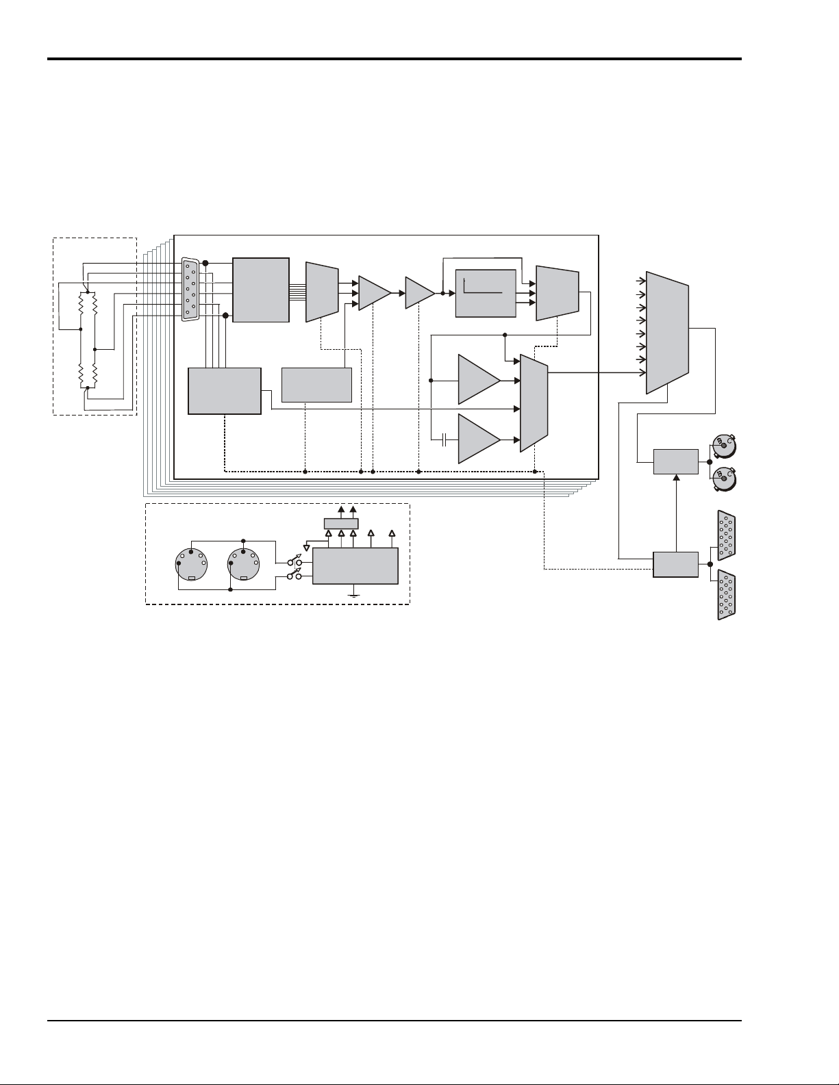
WBK16 - Strain-Gage Module
g
g
Description
WBK16 is an 8-channel strain-gage signal-conditioning module for the WaveBook system. Up to 8 WBK16
modules (64 channels) can be accommodated by the WaveBook and scanned at 1 µs/channel. Almost all
bridge configurations are supported via a bridge-completion network and software. High-gain differentialamplifier applications are also supported. Software controls bridge configuration, gain, offset, excitation
voltage, polarity, filtering, and the calibration process.
Refer to the following block diagram as needed while reading this section.
User Strain Gage
(+)EXC
(+)SENSE
R1R
4
R
R
3
2
(-)SENSE
(-)EXC
Note: Strain-gage
configuration may
vary; see BridgeCompletion
diagrams for
corresponding use
of DB-9 pinouts.
DB-9
BridgeCompletion
and
Shunt Cal
Network
Programmable
Excitation
Regulator with
Remote Sense
Internal DC-DC Power Supply
GND
DIN-5
+V
DC Power Input & Expansion
DIN-5
Input
Config
& Cal
MUX
Programmable
Offset Volta
Reference
+15 V
Filters
Isolated
+5, +12, ±15 VDC
Power Supply
Power
Switch
WBK16 Block Diagram
Gain =
×1,10,
100,1000
PGIA
e
-15 V
+5 V +12 V
Gain =
×1 to 20
PGA
a
LPF
4-pole LowPass Filters
Inverter
Amp
1Hz
h-
Hi
pass
Channel 1 of 8
f
MUX
Output
Selection
MUX
Serial Control Bus
CH8
CH7
CH6
CH5
Channel
CH4
Selection
CH3
MUX
CH2
CH1
WaveBook Analog
Expansion Bus
Analog
Interface
Digital
Interface
WaveBook Digital
Expansion Bus
N
N
DB-15
DB-15
Channel Selection
The eight independent channels are routed to the Channel Selection MUX (multiplexer) for output to the
WaveBook through the Analog Interface. The Digital Interface controls the channel-scanning process and
allows digital configuration of all channels through the WaveBook's Serial Control Bus.
Excitation Source
Excitation power is programmable from a dual source—channels 1 to 4 from one source and channels 5 to 8
from another source. Each channel has a separate regulator with a fold-back current limiter. Up to 85 mA is
provided at 10 V out, decreasing to 30 mA when shorted. This is sufficient current to operate 120 Ω gages
at any voltage. Programmable output voltages of 0, 0.5, 1, 2, 5, and 10 volts are available. Remote-sense
inputs are provided and should be connected at the strain gage for best accuracy. If they are not used, they
need to be jumpered to the excitation output at the connector. The remote-sense inputs are fully differential,
and may even be connected across the completion resistor to form a constant-current linearized
quarter-bridge configuration.
3-22 WBK16, WBK Expansion Options,
ch03B 6-23-99
WaveBook User’s Manual
Page 55
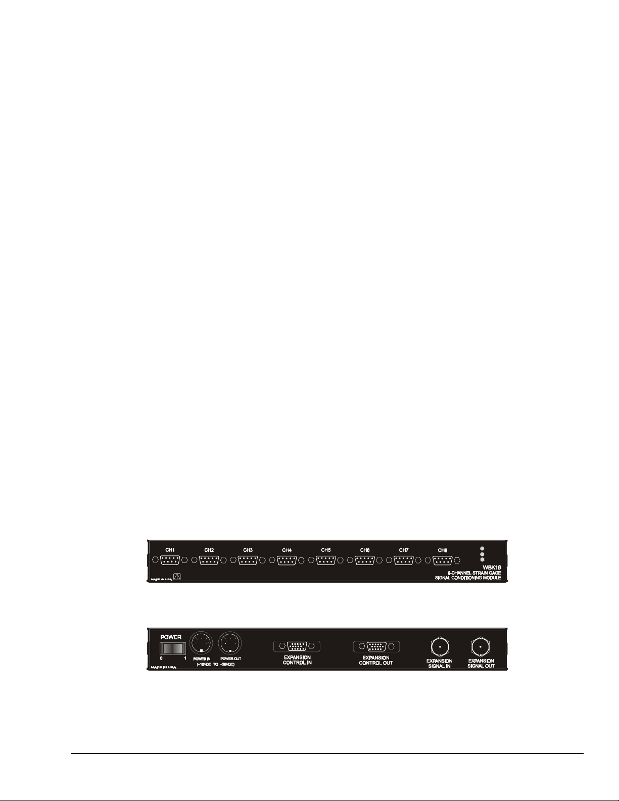
Bridge Configuration
The strain gage is connected to the amplifiers through the Bridge Completion and Shunt Cal Network. This
network consists of user installed resistors for bridge completion. Several combinations of resistors and
three different shunt values may be installed simultaneously. External connector tie points and the
programmable Input Configuration & Cal MUX determine the actual configuration in use. Once the
network is fully configured, most bridge configurations and resistances can be accommodated without reopening the box. The shunt resistors allow each bridge to be put into a known imbalance condition for
setting or verifying channel calibration. Shunt calibration allows a full-scale gain to be set without
physically loading the bridge. The Hardware Setup section, beginning on page 3-24, contains detailed
information. The section also includes discussion of the CN-189, DB9 Adapter option.
Amplifiers
Each channel has an amplifier consisting of two series connected stages. The instrumentation amplifier
(PGIA) has programmable gains of 1, 10, 100, and 1000. A programmable gain amplifier (PGA) follows,
with a gain range of 1 to 20 in 28% steps. This results in a combined programmable gain range of 1 to
20,000 in 28% steps. The optimal gain is automatically determined during the gage calibration process.
Offset Source
A low-drift, programmable offset voltage source with a range of ±3.0 V is used to balance the bridge during
the gage calibration process. This offset source will correct for mismatched bridge resistors and quiescent
loads of the strain gage and still retain the full dynamic range.
Auto-zero removes the static portion of the strain load and zeros the input to compensate for any input drift.
Because this is done electronically, zeroing is independent of the user. Simply select the channels that are to
be auto-zeroed and the WBK16 will complete the task automatically.
Filters
Two different 4-pole Butterworth low-pass noise rejection filters are selectable through software by the
Output Selection MUX. The filters have a nominal cutoff frequency of 10 Hz and 1 kHz. Four SIP resistor
networks allow you to determine two cutoff frequencies. See the
Hardware Configuration
section for
details. If full bandwidth is required, a filter bypass mode is software selectable.
Output Selection
An AC coupling circuit with a 1-Hz cutoff frequency can be software selected by the MUX. This MUX can
also select an Inverting Amplifier for proper output signal polarity. The Inverter avoids having to rewire the
gage if the polarity is reversed. Note that the Inverter option is not available for AC coupling modes.
Front & Rear Panels
WBK16’s front panel has the following connectors and indicators as shown:
ACTIVE
READY
POWER
• 8 DB-9 connectors for bridge input
• 3 LEDs to indicate system status (Active, Ready, Power)
The rear panel has the power switch and the following connectors as shown:
•
• 1 DB-15M expansion control input connector
•
• 2 BNC connectors for analog expansion in and out
WaveBook User’s Manual,
2 5-pin DIN5 connectors for power input and power pass-through
1 DB-15F expansion control output connector
ch03B 6-23-99
WBK Expansion Options, WBK16 3-23
Page 56
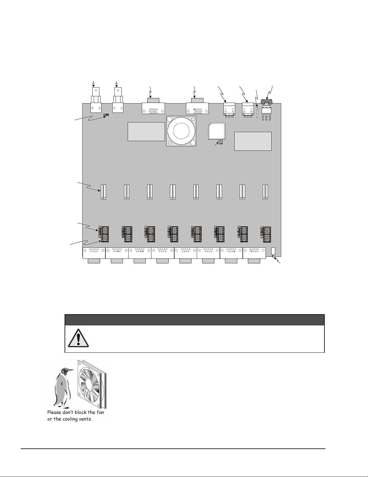
Hardware Setup
Configuration
The figure shows the WBK16 board layout for locating user-accessible components. You may need to refer
to this figure to locate components referenced in the text. The jumper positions are not user functions, and
are only shown for reference in case they are dislodged.
Expansion
Signal Out
Expansion
Signal In Expansion
Control Out
Expansion
Control In
Power Out
Power In
Power Switch
Fuse
Jumper
(Default)
Low-Pass Filter
SIP Resistor Bank
(2 per channel)
Jumper
(Default)
Included
CN-115
Header
(1 per channel)
BNC BNC
Filters
A B
CH1
RH
RA
DB9
CH1
CH2 CH3 CH4
DB15
1
DC/DC CONVERTE R
Filters
A B
CH2
DB9 DB9 DB9 DB9 DB9 DB9
RH
RA
Filters
A B
RH
RA
Filters
A B
DB15
1
FAN
Reserved for
future options
Filters
A B
CH5CH3 CH7
RH
RA
CH5
RH
RA
CH6
Filters
A B
CH6CH4 CH8
RH
RA
CH7
WBK16 Board Layout
DC/DC CONVERTE R
DC/DC CONVERTE R
Filters
A B
RH
RA
DB9
CH8
Filters
A B
RH
RA
LEDs
- Active
- Ready
- Power
Configuration options on WBK16 include:
•
Customization of low-pass filter frequencies using resistor networks
•
Bridge completion resistor installation
• Shunt calibration resistor installation
Be careful to avoid component damage while WBK16 enclosure is open. Always
remove bridge completion headers (CN-115) from the unit before soldering resistors
in the headers.
3-24 WBK16, WBK Expansion Options,
CAUTION
CAUTION
CAUTIONCAUTION
WBK16 Fan
A fan draws air through enclosure vents and exhausts it through the bottom of the
WBK16. To maintain sufficient cooling, it is important to keep the fan and vents free
of obstruction.
Note: The partial blocking of vents by splice plates (in stacked assemblies) does not
jeopardize unit cooling.
ch03B 6-23-99
WaveBook User’s Manual
Page 57

Bridge Applications
WBK16 can accommodate many different strain-gage configurations. All strain-gage bridge configurations
consist of a 4-element network of resistors. The quarter, half or full designation of a strain gage refers to
how many elements in the bridge are strain-variable. A quarter-bridge has 1 strain-variable element; a halfbridge has 2 strain-variable elements; and a full-bridge has 4 strain-variable elements.
Full-bridges generally have the highest output and best performance. Output signal polarity is determined
by whether the strain-variable resistance increases or decreases with load, where it is located in the bridge,
and how the amplifier inputs connect to it. Configuration polarity is not important in WBK16, due to an
internal software-selected inversion stage. This simplifies bridge configuration.
Each WBK16 channel has locations for five bridge-completion resistors. These BCR’s are for use with
quarter
and
half-bridge
strain gages. The resistors make up the fixed values necessary to complete the
4-element bridge design.
A full-bridge gage requires no internal completion resistors, but they may still be installed for other
configurations in use. The additional resistors will be ignored when the software has selected full-bridge
mode. Both quarter- and half-bridge gages require an internal half-bridge consisting of header positions Rg
and Rh. The recommended minimum values are 0.1%, <5 PPM/°C drift, 1 KΩ, and 0.25-watt resistors.
Lower values will dissipate more power and add heat. Values >1KΩ will increase the amount of drift and
noise. The same value half-bridge resistors can be used for any resistance strain gage. This internal halfbridge will be automatically selected by the software when needed.
Internal 1 MΩΩΩΩ shunt resistors are used to avoid open circuits.
These resistors are not suitable for high-accuracy/low-noise applications.
A quarter-bridge gage additionally requires a resistor of equal value to
itself. Up to 3 different values may be installed simultaneously in header
positions Ra, Rc, Re. All of these resistors are connected to the (-)
excitation terminal. An external jumper at the input connector determines
which resistor is utilized. Therefore, 3 different quarter-bridge values can
be supported without opening the enclosure. Each different value bridge
would simply have the jumper in a different location; when the gage is
plugged in, the proper resistor is then already selected. Configurations
with the completion resistor on the (+) excitation are redundant, due to
the internal inversion stage, and not used.
Kelvin-Type Excitation Leads
The bridge-configuration figures in the following text show various strain-gage configurations divided into
4 groups: Full-bridge, half-bridge, quarter-bridge, and high-gain voltmeter. Many of these configurations
can coexist but are shown individually for clarity.
Excitation Connection
Remote sense inputs are provided for the excitation regulators. The excitation voltage will be most accurate
at points where remote sense lines are connected—preferably at the bridge (this is often referred to as a 6wire connection). Long cables will reduce the voltage at the bridge, due to current flow and wire resistance,
if remote sense is not used. If the 6-wire approach is not used, the remote sense inputs must be jumpered to
the excitation outputs at the input connector. Internal 1 MΩ resistors are also connected where the jumpers
would be located to prevent circuit discontinuities. These 1 MΩ resistors are not suitable for high-accuracy
excitation-voltage regulation. 3-wire quarter-bridge configurations do not benefit from external remote
sense connections—the lead resistance is actually a balanced part of the bridge. If the + remote sense input
is connected to the + input on a quarter-bridge, the voltage is regulated across the bridge completion
resistor. This results in a constant-current linearized quarter-bridge; otherwise, quarter-bridges are not
perfectly linear.
WaveBook User’s Manual,
ch03B 6-23-99
WBK Expansion Options, WBK16 3-25
Page 58

Shunt-Calibration Resistors. WBK16 provides three physical locations for internal shunt-calibration
resistors for each channel. Each shunt resistor is switched in from the EXCITATION (-) to the IN (+) of the
Instrumentation Amp by a FET switch to create a repeatable bridge imbalance. Internal resistance of the
circuit is about 1 kΩ; the exact amount is automatically accounted for in the software. The software also
allows selection of the three shunt resistors ( B, D, F ). An internal inversion stage insures correct polarity
during the shunt calibration process; which arm is shunted is therefore irrelevant. Header positions Rb, Rd,
Rf correspond to the software shunt resistor selections of B, D, F.
For any balanced bridge, a resistance value can be placed in parallel with one element to create a
predictable imbalance and output voltage. This shunt-resistance value can be calculated by the following
equation, where V
Example:R
R
Shunt
Shunt
= 350 [ ( 10 / 4(0.020)) - 0.5 ] = 43,575Ω
is the differential output voltage of the gage.
out
= R
Bridge Arm
[ ( V
Excitation
/ 4 (V
)) - 0.5 ]
out
Configuring the Bridge Completion Resistor Modules.
CAUTION
CAUTION
CAUTIONCAUTION
Be careful to avoid component damage while WBK16 enclosure is open. Always
remove bridge completion headers (adapter plugs) from the unit before soldering
resistors in the headers.
For each channel, the board has a 2×8 resistor socket with rows designated
A through H. The removable adapter plugs are included for soldering in the
resistors. Additional adapter plugs are available for convenient change-over of
Solder resistor lead
into support fork.
alternate configurations. Resistor Ra is located nearest the front panel.
• Half-bridge completion resistors consist of Rg and Rh.
•
Quarter-bridge completion resistors consist of Ra, Rc, and Re.
• Shunt resistors consist of Rb, Rd, and Rf.
Inserting resistors directly into the socket makes an unreliable connection and is
not recommended. Solder resistors to the adapter plug as shown. Remove the
plug from the main board. To avoid damaging the pin alignment on the plug,
solder with minimal heat. After soldering, the resistor leads should be snipped
off close to the support.
Soldering Resistors to
Adapter Plug
3-26 WBK16, WBK Expansion Options,
ch03B 6-23-99
WaveBook User’s Manual
Page 59

Low-Pass Filter Customization
WBK16 has 68 kΩ 4-resistor SIP networks installed from the factory. These networks result in a 10.9 Hz
cutoff for filter A and a 1.09 kHz cutoff for filter B. The 4-resistor SIP networks are socketed and can be
altered to the range of values in the table below. Individual resistors may also be used but should be
matched within 2%. Cutoff frequency accuracy is about ±5%.
If you change the filter nominal values, be sure to update the filter cutoff frequencies in
the WaveView software. This is discussed in the section, WaveBook Advanced Features,
on page 3-43.
Resistor Filter A Resistor Filter B
330 kΩ
450 kΩ
120 kΩ
100 kΩ
82 kΩ
68 kΩ
47 kΩ
33 kΩ
22 kΩ
15 kΩ
10 kΩ
8.2 kΩ
6.8 kΩ
4.7 kΩ
3.3 kΩ
3 to 330 kΩ
2.20 Hz
4.95 Hz
3.37 Hz
7.42 Hz
9.05 Hz
10.9 Hz
15.8 Hz
22.5 Hz
33.7 Hz
49.5 Hz
74.2 Hz
90.5 Hz
109 Hz
158 Hz
225 Hz
R=742K/f
330 kΩ
450 kΩ
120 kΩ
100 kΩ
82 kΩ
68 kΩ
47 kΩ
33 kΩ
22 kΩ
15 kΩ
10 kΩ
8.2 kΩ
6.8 kΩ
4.7 kΩ
3.3 kΩ
cut
3 to 330 kΩ
225 Hz
495 Hz
337 Hz
742 Hz
905 Hz
1.09 kHz
1.57 kHz
2.25 kHz
3.37 kHz
4.95 kHz
7.42 kHz
9.05 kHz
10.9 kHz
15.8 kHz
22.5 kHz
R=74.2M/f
cut
Lower frequency filters, such as the 10-Hz filter provided, are generally used to reduce higher frequency
noise. Some common sources of noise are: 50/60 Hz power line pickup on long cables, electromagnetic
interference (EMI) from nearby equipment, unwanted vibrations in the strain gage system itself, or at higher
gains, the intrinsic thermal noise of the amplifiers. All information above the cutoff will also be lost due to
the filter’s function.
The 1-kHz filter provided is typically used as an anti-aliasing filter, or for slight noise reduction while still
maintaining moderate bandwidth.
Reference Note:
The next several pages contain schematics of various bridge configurations. Page 3-32
contains DB9 connector information, including use of the optional CN-189, DB9 Adapter.
WaveBook User’s Manual,
ch03B 6-23-99
WBK Expansion Options, WBK16 3-27
Page 60

Full-Bridge Configurations
The full-bridge has four strain-variable elements and requires no bridge completion components. Quarter
and half-bridge resistors may be left installed. Any bridge resistance from 60 to 1000 ohms can be
accommodated.
+Sense
+Excitation
RH
5
9
4
8
3
7
2
6
1
Externa l
Bridge
DB-9
Input
RARBRCRDRERFRG
Internal Bridge Completion
Full-Bridge (+), Any Resistance from 60 to 1000 Ohms
5
9
4
8
3
7
2
6
1
Externa l
Bridge
DB-9
Input
RARBRCRDRERFRG
Internal Bridge Completion
Full-Bridge (+), with Remote Sense
JN01
JN01
3
2
1
IA
In this connection, excitation voltage is
Switches
accessed
through
software
-Excitation
-Sense
+Sense
+Excitation
RH
3
2
1
IA
regulated at the connector. This
configuration should only be used for
short cable lengths. Output polarity may
be altered by interchanging the (+) and (-)
input or by selecting the software invert
function.
In this connection, excitation voltage is
Switches
accessed
through
software
-Excitation
-Sense
regulated at the strain gage. This
eliminates errors due to cable losses and
is the preferred connection for longer
cables.
5
9
4
8
3
7
2
6
1
Externa l
Bridge
DB-9
Input
Full-Bridge (+), with B, D, or F Shunt
3-28 WBK16, WBK Expansion Options,
RH
3
JN01
2
1
RARBRCRDRERFRG
Internal Bridge Completion
ch03B 6-23-99
Switches
accessed
through
software
+Sense
+Excitation
IA
-Excitation
-Sense
The B, D, or F shunt resistor may be
software selected when installed as
shown. Output polarity during shunt
calibration will be automatically corrected
by software. The shunt resistor value will
typically be different for each value of
bridge resistance.
WaveBook User’s Manual
Page 61

Half-Bridge Configurations
The half-bridge has two strain-variable elements and requires two internal bridge completion resistors
(BCRs). Any bridge resistance from 60 to 1000 ohms can be accommodated for either the internal or
external bridge.
+Sense
+Excitation
RH
5
9
4
8
3
7
2
6
1
Externa l
Bridge
DB-9
Input
RARBRCRDRERFRG
Internal Bridge Completion
Half-Bridge (+), Any Resistance from 60 to 1000 Ohms,
B,D, or F Shunt
JN01
3
2
1
IA
In this connection, excitation voltage is
Switches
accessed
through
software
-Excitation
-Sense
regulated at the connector. This
configuration should only be used for
short cable lengths. Output polarity can
be altered by selecting the software invert
function. The B, D, or F shunt resistor
may be software selected. Output polarity
during shunt calibration will be
automatically corrected by software.
+Sense
+Excitation
RH
JN01
3
2
1
IA
In this connection, excitation voltage is
Switches
accessed
through
software
-Excitation
-Sense
regulated at the strain gage. This is the
preferred connection for longer cables.
Externa l
Bridge
5
9
4
8
3
7
2
6
1
DB-9
Input
RARBRCRDRERFRG
Internal Bridge Completion
Half-Bridge (+), with Remote Sense
Externa l
Bridge
3-Wire TC Half-Bridge, Software Invert & B, D, F Shunt Available
WaveBook User’s Manual,
5
9
4
8
3
7
2
6
1
DB-9
Input
ch03B 6-23-99
RH
3
JN01
2
1
RARBRCRDRERFRG
Internal Bridge Completion
Switches
accessed
through
software
+Sense
+Excitation
IA
-Excitation
-Sense
This occasionally utilized connection can
be made as shown. Two resistors
normally reserved for quarter-bridge
completion must be used. For
compatibility with other configurations,
the above two configurations are
preferred instead of this one.
WBK Expansion Options, WBK16 3-29
Page 62

Three-Wire Quarter-Bridge Configurations
The three-wire quarter-bridge has only one strain-variable element and requires three bridge completion
resistors (BCRs). The internal half-bridge may be any two matched values, but the remaining resistor must
match the external quarter-bridge value precisely. Three of these values may be installed simultaneously
when connected as shown below; the connector pins determine which resistor is used. With all three values
installed, WBK16 can accommodate all three quarter-bridge values without changing the internal resistors.
+Sense
+Excitation
RH
JN01
JN01
3
2
1
IA
A 120-ohm resistor and its corresponding
Switches
accessed
through
software
-Excitation
-Sense
+Sense
+Excitation
RH
3
2
1
IA
shunt value may be installed as shown.
A 350-ohm resistor and its corresponding
Switches
accessed
through
software
-Excitation
-Sense
shunt value may be installed as shown.
Externa l
Bridge
Externa l
Bridge
5
9
4
8
3
7
2
6
1
DB-9
Input
RARBRCRDRERFRG
Internal Bridge Completion
Three-Wire Quarter-Bridge (+),
Using RA (120-Ohm nominal), B Shunt Resistor
5
9
4
8
3
7
2
6
1
DB-9
Input
RARBRCRDRERFRG
Internal Bridge Completion
Three-Wire Quarter-Bridge (+),
Using RC (350-Ohm nominal), D Shunt Resistor
5
9
4
8
3
7
2
6
1
Externa l
Bridge
DB-9
Input
Three-Wire Quarter-Bridge (+),
Using RE (1-KOhm nominal), F Shunt Resistor
3-30 WBK16, WBK Expansion Options,
3
JN01
2
1
RARBRCRDRERFRG RH
Internal Bridge Completion
ch03B 6-23-99
Switches
accessed
through
software
+Sense
+Excitation
IA
A 1000-ohm (or other value) resistor and
its corresponding shunt value may be
installed as shown.
-Excitation
-Sense
WaveBook User’s Manual
Page 63

High-Gain Amplifier Configurations
WBK16 is also useful as a programmable high-gain amplifier. No external bridge is used in these cases.
The inputs are fully differential.
Note: The differential inputs are not isolated inputs. Common mode voltage should not exceed ±10 V.
+Sense
+Excitation
RH
5
9
8
7
6
DB-9
Input
4
3
2
1
RARBRCRDRERFRG
Internal Bridge Completion
Externa l
Bridge
+
-
Universal High-Gain Amplifier Input, Differential
JN01
3
2
1
IA
No pull-down resistors are required if the
Switches
accessed
through
software
-Excitation
-Sense
+Sense
+Excitation
input signal ground is connected to Pin 1
as shown.
JN01
3
2
1
IA
Switches
accessed
through
software
-Excitation
-Sense
Externa l
Bridge
5
9
8
7
6
DB-9
Input
4
3
2
1
RARBRCRDRERFRG RH
Internal Bridge Completion
+
-
Universal High-Gain Amplifier Input, Differential with Pull Downs
+Sense
+Excitation
RH
JN01
3
2
1
IA
Switches
accessed
through
software
-Excitation
-Sense
Externa l
Bridge
5
9
8
7
6
DB-9
Input
4
3
2
1
RARBRCRDRERFRG
Internal Bridge Completion
+
Universal High-Gain Amplifier Input, Single-Ended
A floating input without a ground
reference, such as a battery, requires a
path for input bias currents. Pull-down
resistors of 1k to 10MΩ may be installed
as shown to provide this function.
A 10MΩ resistor would be suitable in
most cases. These resistors are not
compatible with other bridge
configurations.
If the (-) input is ground referenced, the
input is non-differential and pull-down
resistors are not required. A floating
source would still result in a truly
differential input.
WaveBook User’s Manual,
ch03C 6-21-99
WBK Expansion Options, WBK16 3-31
Page 64
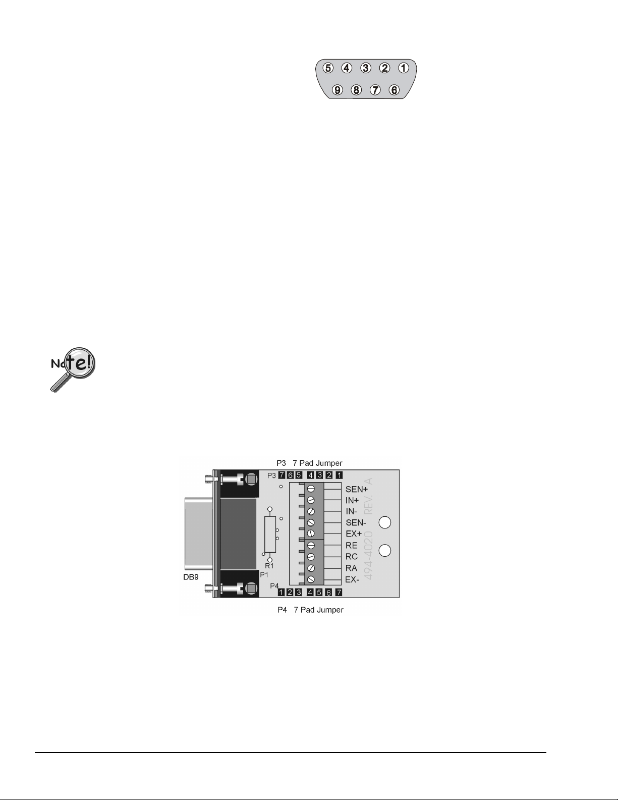
Connection
The figure shows the pin numbers of the
DB-9 connector (1 of 8) on WBK16’s
front panel. The strain gage will connect
to these pins, unless the CN-189, DB9
Adapter option is used. The CN-189
option is discussed in the following
WBK16 Signal Input Connection
DB-9 pinout per channel
Note that
orientation applies to
connectors on the WBK16
front panel,
connected to the sensor.
pin-number
not to plugs
sub-section.
Quality cable (such as the CA-177 strain-gage cable) can improve performance of the system, especially
with long cable runs. Use cable with an overall shield connected to the DB9 metal shell. Twisted pair cable
with paired leads for signal input, excitation output, and remote sense input is also beneficial. The wires
should be soldered to the DB9 to eliminate noise created by contact resistance variations. The protective
hoods should be installed over the 9-pin connectors during use to avoid draft-induced thermal-electric noise
in the connector solder joints. Molded cables wider than 1.23 inches will not fit WBK16's connector
spacing.
CN-189, DB9 Adapter Option
The CN-189 option consists of two 7-pad jumpers (P3 and P4), a DB9 connector, and a 9-slot screwterminal block. The adapter plugs into WBK16’s Signal Input DB9 connector. With use of the terminal
block and appropriate shorting of jumper pads, the user can easily set up the desired bridge configuration.
A table indicating bridge types and the respective CN-189 jumper pad shorts follows shortly. In some
cases, the user may want to install a resistor at location R1. The electrical relation of CN-189 components
is shown in the following schematic.
The CN-189 is intended for convenience and is not shielded. Higher signal quality will be obtained
with the use of shielded cables (such as the CA-177 strain gage cable).
CN-189, DB9 Adapter Option
3-32 WBK16, WBK Expansion Options,
ch03C 6-21-99
WaveBook User’s Manual
Page 65

CN-189 Schematic
CN-189 DB9 Adapter for WBK16, Configuration Table
Function P3 P4 Resistor Used in R1
1 Internal Excitation Sense Short 1 and 2 Short 6 and 7
2 ¼ Bridge Using (RA) 2-Wire Short 3 and 4
3 ¼ Bridge Using (RC) 2-Wire Short 5 and 6
4 ¼ Bridge Using (RE) 2-Wire Short 6 and 7
5 High Gain Amp Ground Path (Short) Short 5 and 6
6 High Gain Amp (Resistive) Ground Path (EXT) Resistor between 5 and 6
7 High Gain Amp (RE) Ground Path (INT) Short 1 and 2
8 High Gain Amp (RC) Ground Path (INT) Short 2 and 3
9 High Gain Amp (RA) Ground Path (INT) Short 4 and 5
10 Current Measurement (Differential) Shunt resistor in R1
11 Differential Load Resistor Load resistor in R1
For the functions listed in the preceding table, internal WBK16 configurations
still apply as indicated on pages 3-28 through 3-31.
Power
WBK16 requires an input voltage between +10
and +30 VDC. The DC source should be filtered
but not necessarily regulated—the TR-40U AC
power adapter is recommended for AC line
applications.
WBK16 may be powered with the supplied AC
adapter that plugs into any standard AC wall
outlet or from any isolated 10-30 VDC source of
at least 25 W (see figure). Before plugging unit
in, make sure the power switch is in the “0”
(OFF) position.
If you are using an AC power adapter, plug it into an AC outlet and attach the low voltage end to WBK16’s
DIN5 jack. If you are using another source of power, make sure leads are connected to the proper DIN5 terminals
as shown in the figure.
WaveBook User’s Manual,
AC
Power
Source
Power
Switch
AC
Power
Adapter
Power Input
Connectors
+V
10 to 30 VDC
+
GND
WBK16 Rear Panel
WBK16 Power Connections
CAUTION
CAUTION
CAUTIONCAUTION
Do not exceed the 5 amp maximum DC current limit of the POWER IN and POWER OUT
DIN connectors.
ch03C 6-21-99
WBK Expansion Options, WBK16 3-33
Page 66
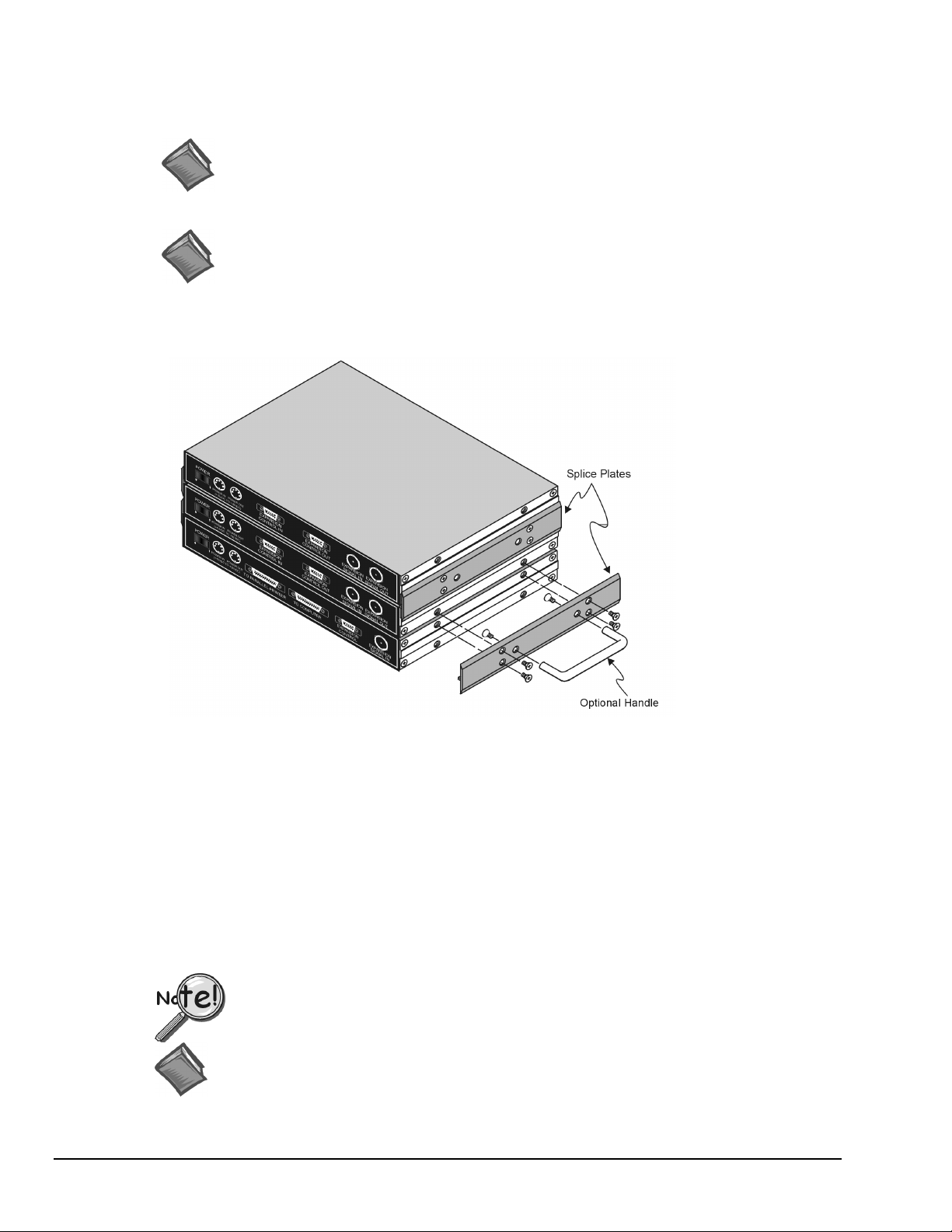
Internal DC to DC converters provide properly isolated and regulated +15V, +12V, and +5V from the
single 10 to 30 VDC external source. Excitation power is derived from these internal converters. An
internal replaceable fuse rated at 4 A provides overload protection. For replacement, use a
Littelfuse #251004. Reversed input polarity is the usual cause of a blown fuse.
Reference Note:
The WBK16 fuse (Littelfuse #251004, rated at 4A) is located on the board, between the
Power Switch
and the
Power In
connector. Refer to page 3-24 for board layout, if needed.
Reference Note:
For detailed WaveBook power information, see chapter 4:
System Power & Assembly
Using Splice Plates to Stack Modules
.
Attaching Splice Plates to a WaveBook and two WBK Modules (the handle is optional)
WBK10/10H, WBK14, WBK15, and WBK16 are shipped with a splice plate kit. Each kit includes two
metal plates that screw onto the sides of stacked modules. The plates provide a means of stacking modules
to create one rigid assembly. Optional handles can be attached to the splice plates, if desired.
Note:
Splice plates will partially block the vents on WBK16s and WaveBook/516s when stacked.
This partial blocking of vents does not jeopardize the cooling process.
Software Setup
WaveView contains special software features for WBK16. The WBK Sensor Configuration aspect of
WaveView is discussed in the following pages.
WBK16 support is only available with the 32-bit driver and 32-bit version of WaveView.
Reference Notes:
For information regarding software setup, refer to the
For detailed information regarding
3-34 WBK16, WBK Expansion Options,
ch03C 6-21-99
WaveView
Software Setup
, refer to chapter 5.
section in chapter 2.
WaveBook User’s Manual
Page 67

Using the Sensor Calibration Program in WaveView
To launch WaveView, double click on the WaveView icon in the WaveView program group. WaveView
holds user-configured parameters that can be saved to disk. The default configuration filename is
WAVEVIEW.CFG. When WaveView starts up, it proceeds to search the working directory for this file.
WaveView also holds a default sensor calibration file. The
WAVEVIEW.CFG file holds the name of this
calibration file so that all sensor calibration information from the last WaveView session is also loaded into
WaveView during initial boot-up.
•
If the default configuration file is found, all the required setup information will be extracted from it,
and the application’s main window will open.
•
If connection is established, the application’s main window will open with the default setting.
If these options fail, a dialog box will ask if you want to open a different setup file. For detailed WaveView
startup information, refer to chapter 5:
WaveView
.
Once WaveView has been launched, you can load a previously saved WBK16 sensor calibration file by
clicking on the
a WBK16 Cal File
column from the menu. A drop down menu appears. Click on the fourth selection,
File
.
Load
Once you choose to open a previously saved calibration file, a standard dialog box appears. Choose the file
you want to open and click on the
Open
button.
Clicking on the toolbar’s WBK16 Sensor Configuration button (depicted at the left), will also bring up the
sensor window.
Sensor Configuration Main Components
Once you enter the WBK16 Sensor Calibration Program from WaveView, the
Configuration
window appears.
WBK16 Sensor
WaveBook User’s Manual,
ch03C 6-21-99
WBK16 Sensor Configuration Window
WBK Expansion Options, WBK16 3-35
Page 68

Sensor Configuration Toolbar and Pull-Down Menus
Control functions in the sensor configuration window are available through the pull-down menus or the
toolbar. For descriptions of button functions, see the related menu selections. Note that some menu
selections have no corresponding button.
WBK16 Sensor Configuration Window Toolbar
1 – Load an Existing Configuration
2 – Save Current Configuration
3 – New Configuration
4 – Take a Single Reading
5 – Calibrate Enabled Channels
6 – Return to WaveView
File
The
menu provides four functions:
File
Load an Existing Configuration
Save Current Configuration
New Configuration
Return to WaveView
Load a saved sensor calibration configuration.
Save the current sensor calibration configuration for later recall.
Set all parameters to their default startup setting.
Exit the WBK16 Sensor Configuration window and return to WaveView.
Calibration
The
Calibration
Take a Single Reading
Calibrate Enabled Channels
menu provides two functions:
This command allows the user to take a single reading and display the values in
the WBK16 Sensor Configuration window.
This command will calibrate all enabled channels.
Password
The sensor calibration application provides password protection. If you calibrate any WBK16 channels and
then choose the password protection option, WaveView will prevent other users from making changes to
your calibration file. The
Password
menu provides three functions:
Enter Password
Set a New Password
Clear Password
3-36 WBK16, WBK Expansion Options,
ch03C 6-21-99
Use this command to enter a previously selected password, enabling you to
change parameters.
This command allows the user to select a 4-7 character password. A message
box will prompt you to enter a new password. Type a password and press
“enter”, or click on the “OK” button.
This command clears the password protection. A message box will prompt you
to enter the current password. Type the current password and press “enter”, or
click on the “OK button.
WaveBook User’s Manual
Page 69

The following text pertains to other areas of the configuration window, including the spreadsheet columns.
Status Label
The
top of the
of the
• Configuring Channels. When the
label describes the current state of the sensor calibration spreadsheet. This label is located at the
Status
WBK16 Sensor Calibration
label are as follows:
Status
window to the right of the strain gage diagram. The 3 possible states
label displays “Status: Configuring Channels,” the user can
Status
enter parameters for a calibration into the spreadsheet cells.
• Calibrating Channel X-Y. If the user selects
the toolbar, the
label will read “Status: Calibrating Channel X-Y” where X and Y correspond
Status
Calibrate Enabled Channels
to the module number (X) and the channel number (Y) being calibrated.
• Reading Channel X-Y. If the user selects
toolbar, the
label will read “Status: Reading Channel X-Y” where X and Y correspond to the
Status
Take a Single Reading
module number (X) and the channel number (Y) being read.
, either from the menu bar or
either from the menu bar or the
WaveBook User’s Manual,
ch03C 6-21-99
WBK Expansion Options, WBK16 3-37
Page 70
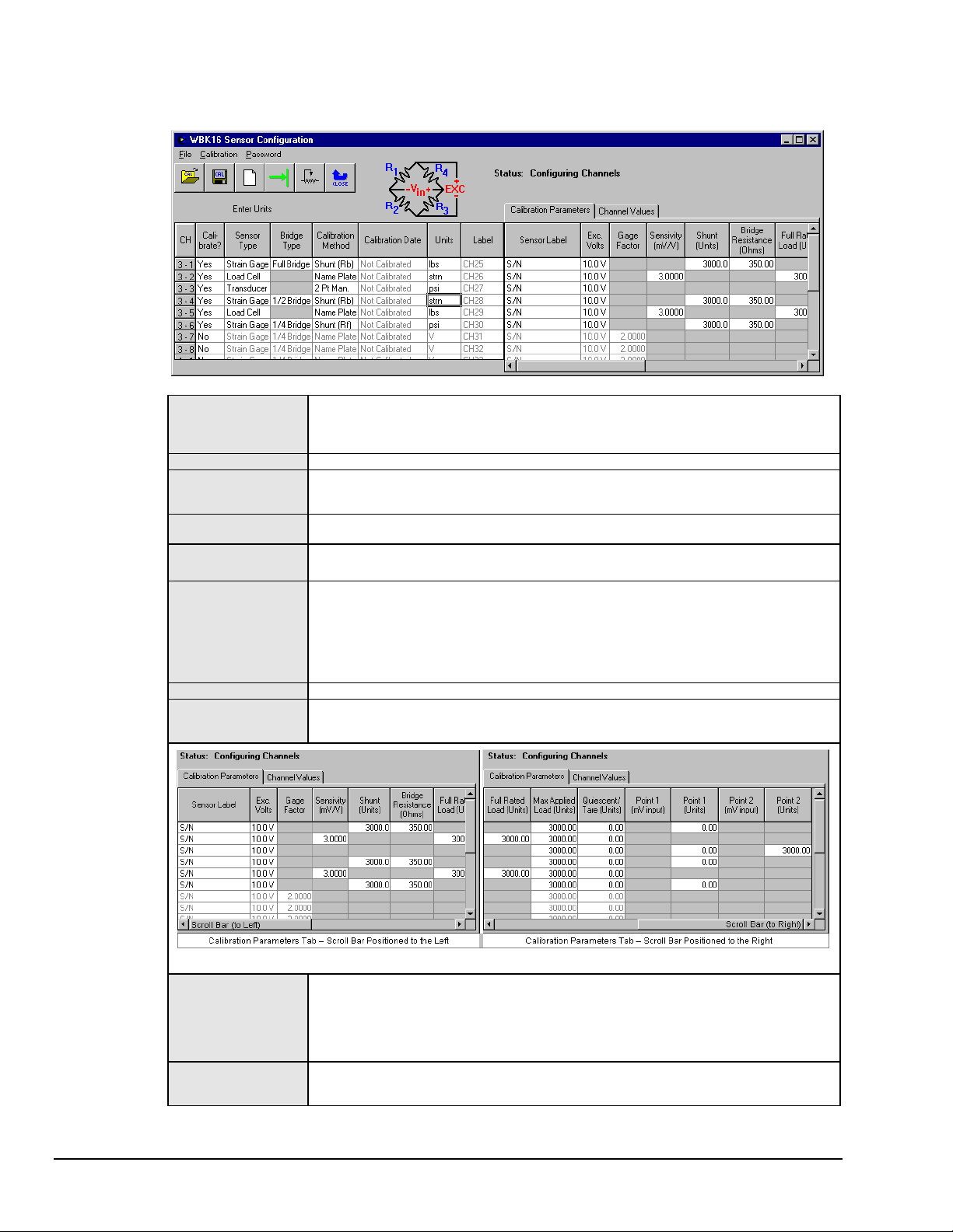
Calibration Parameters Tab selected
Note: The Calibration Parameters tab has more columns than can be display at once. For this reason, two
images are provided (scroll bar to the left and scroll bar to the right).
WBK16 Sensor Configuration Window
Calibrate?
Sensor Type
Bridge Type
Calibration Method
Calibration Date
Units
Label
Sensor Label
Choosing “yes” will enable the selected channel to be calibrated with the “calibrate enabled
channels” option. Selecting “no” will disable the channel from being calibrated. All other
columns for that channel will be disabled if “no” is selected. The channel can still be turned
on in WaveView.
Choose the sensor type from strain gage, load cell, or transducer.
Choose the bridge type from full-bridge, half-bridge, or quarter-bridge. This option is only
available for a strain gage sensor in the calibration program. The bridge type for any
sensor can be changed from the WBK16 Sensor Configuration window.
Choose the calibration method from Name Plate, Shunt (Ra), Shunt (Rb), Shunt (Rc), 2-
Point Manual, or 2-Point Automatic. Calibration methods are explained later in the manual.
This column displays the time and date that the channel was calibrated. If the channel has
not been calibrated, “Not Calibrated” appears in the box.
To change the units: highlight the desired box, type-in the new parameters, and then press
<Enter> on the keyboard or select another box with the mouse. Up to 5 characters can be
entered into this column. To fill the entire column with the value of channel one, make sure
“yes” is selected in the “Calibrate” column. Then click on the column label with the mouse.
A message box will appear. Click on “yes”. All channels with the “calibrate” function
enabled will be filled. Changing the units here will also change the units column in the
WaveView Configuration main window.
Identifies the channels.
A serial number or other identifying label for the sensor can be entered here. Up to 39
characters may be entered and 16 will be displayed. The fill option is available for this
column (see Units).
Exc. Volts
Gage Factor
3-38 WBK16, WBK Expansion Options,
Calibration Parameters Section of Window, Two Views
This column is used to change the excitation voltage. Choose between 10.0, 5.0, 2.0, 1.0, .5,
and off. Changing the excitation voltage on any channel between one and four will change
the value on all four lower channels. Likewise, changing the excitation voltage on any
channel five through eight will change the value on all four upper channels. Changing the
Excitation Voltage here will also change the Source Level column in the WaveView
Configuration main window.
This column is used for calibrating strain gages using the Name Plate calibration method. To
change this value, select the box and enter a number greater than 0 and less than 1000.
The fill option is available for this column (see Units).
ch03C 6-21-99
WaveBook User’s Manual
Page 71

Sensitivity (mV/V)
Shunt
(Units)
Bridge Resistance
(Ohms)
Full Rated Load
(Units)
Max Applied Load
(Units)
Quiescent/Tare
(Units)
Point 1 (mV input)
Point 1 (Units)
Point 2 (mV input)
Point 2 (Units)
This column is used for calibrating a load cell or transducer using the Name Plate calibration
method. To change this value, select the box and enter a number greater than 0 and less
than 1000. The fill option is available for this column (see Units).
This column is used for calibrating any sensor using the Shunt calibration method. The value
must equal the value of the shunt resistor in desired units. To change the value, select the
box and enter a number greater than 0 and less than 1000000. The shunt value must not
exceed the value entered as the maximum load. The fill option is available for this column
(see Units).
This column is used for calibrating any sensor using the Shunt calibration method. The value
refers to the bridge arm that is shunted during shunt calibration. To change the value,
select the box and enter a number from 60 to 1000. The fill option is available for this
column (see Units).
This column is used for calibrating a load cell or transducer using the Name Plate calibration
method. To change this value, select the box and enter a number greater than 0 and less
than 100000. The full-rated load must be greater than the value entered for the maximum
applied load. The fill option is available for this column (see Units).
This column is used for calibrating any sensor using any calibration method. To change the
value, select the box and enter a number greater than 0 and less than 1000000. This value
must be greater than the quiescent/tare value. The fill option is available for this column
(see Units).
This column is used for calibrating any sensor using any calibration method. The value
entered is the value of the quiescent load on the sensor. To change the value, select the
box and enter a number between –1000000 and 1000000. This value must be less than
the maximum applied load value. The fill option is available for this column (see Units).
This column is used for calibrating any sensor using the Shunt or 2-Point Automatic
calibration method. The number must equal the input value, in mV, of the first point in the
calibration. To change the value, select the box and enter a number between -10000 and
10000. The fill option is available for this column (see Units).
This column is used for calibrating any sensor using the Shunt, 2-Point Automatic, or 2-Point
Manual calibration method. The number must equal the value, in the selected units, of the
first point in the calibration. To change the value, select the box and enter a number
between -1000000 and 1000000. The fill option is available for this column (see Units).
This column is used for calibrating any sensor using the 2-Point Automatic calibration
method. The number must equal the input value, in mV, of the second point in the
calibration. To change the value, select the box and enter a number between -10000 and
10000. The fill option is available for this column (see Units).
This column is used for calibrating any sensor using the 2-Point Automatic, or 2-Point
Manual calibration method. The number must equal the value, in the selected units, of the
second point in the calibration. To change the value, select the box and enter a number
between -1000000 and 1000000. The fill option is available for this column (see Units).
WaveBook User’s Manual,
ch03C 6-21-99
WBK Expansion Options, WBK16 3-39
Page 72
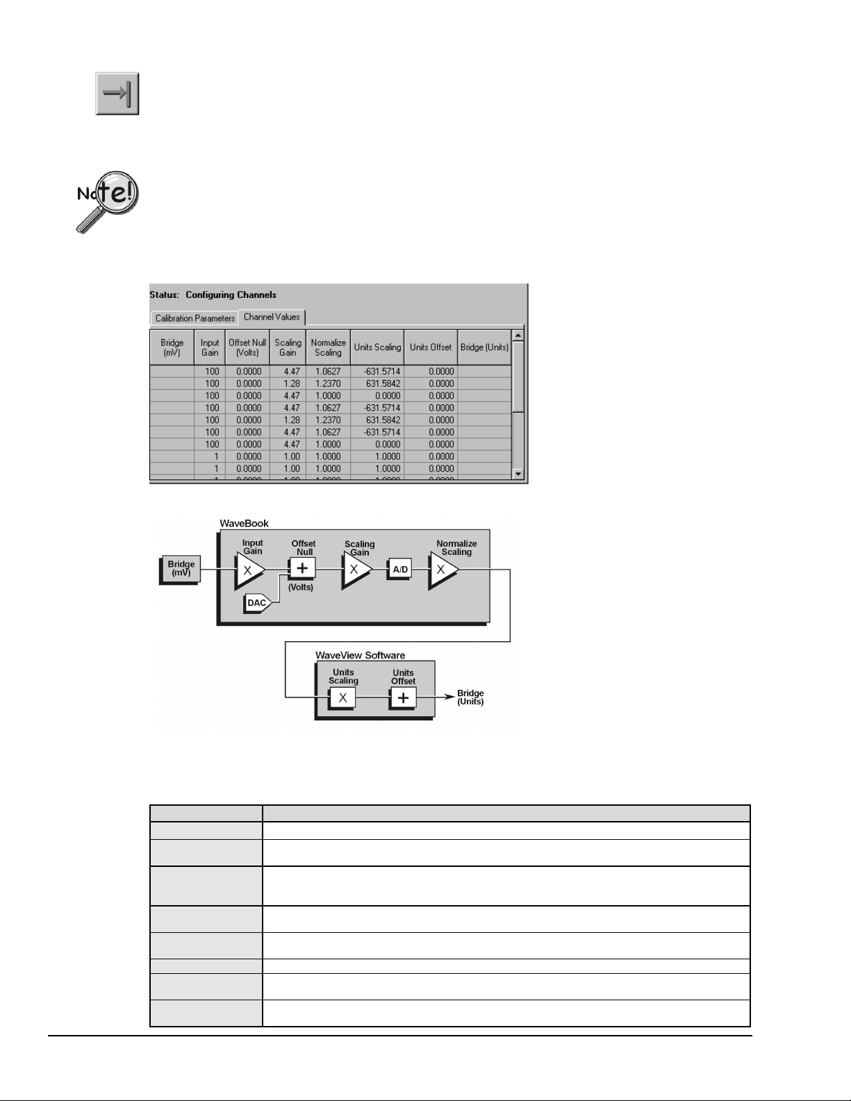
Displaying a Single Reading. In the WBK16 sensor calibration program, it is possible to take a single
reading and display it in the
Then click on the
Calibration
Take a Single Reading
menu item.
WBK16 Sensor Configuration
button on the tool bar, or choose
window. First, click on the
Take a Single Reading
Channel Values
from the
tab.
Displayed readings are based on the most recent calibration. Changing the calibration parameters,
without calibrating the system, will not affect the channel values.
Channel Values Tab
Channel Values Tab
Channel Values, Simplified Block Diagram
The simplified block diagram (above) can be used to better understand the relationship of channel amplifiers and their
corresponding user interface columns (visible in the Channel Values Tab). These columns are represented in the tab
figure, and in the following table.
Column Display Description
Bridge (mV)
Input Gain
Offset Null (Volts)
Scaling Gain
Normalize Scaling
Units Scaling
Units Offset
Bridge (Units)
The input value from the bridge. The value is in millivolts.
The Gain setting of WBK16’s Input Amplifier. Any one of the following four settings is possible:
x1, x10, x100, or x1000.
The Voltage summed into WBK16s Scaling Amplifier. The voltage is to compensate for any
offset that is present in the sensor’s output. The Offset Null voltage is in the range of -3 to +3
volts.
The Gain setting of WBK16’s Scaling Amplifier. Any one of the following 13 gain settings can
be used: 1.0, 1.28, 1.65, 2.11, 2.71, 3.48, 4.47, 5.47, 7.37, 9.46, 12.14, 15.58, or 20.0.
The Multiplier value applied to the A/D converter output for fine adjustment. The value range
for the Multiplier is 1 to 2.
The Multiplier value [used by the software] for converting sensor output voltage into User Units.
The Offset value that is added to “Units Scaling” for fine adjustment of what will be the final
reading (Bridge Units).
The Reading (in User Units, for example: lbs, psi, kg) that results from converting the initial
sensor reading (Bridge mV).
3-40 WBK16, WBK Expansion Options,
ch03C 6-21-99
WaveBook User’s Manual
Page 73

Calibrating a Sensor Using the Sensor Calibration Program
Before proceeding with calibration, remember to enter your password. The password
must be entered before channel parameters can be changed.
Unless all of the parameters (for each channel to be calibrated) are accurately entered
into the spreadsheet, the calibration will produce incorrect results.
The WBK16 sensor calibration program uses four basic methods of calibration: Name Plate, Shunt, 2-Point
Manual, and 2-Point Automatic. All four methods require values for the excitation voltage, maximum
applied load, and quiescent/tare for all sensor types.
Required
Calibration
Parameters
Excitation Voltage
Max. Applied Load
Quiescent/Tare
Gage Factor
Sensitivity
Full Rated Load
Shunt Load Value
Bridge Resistance
Point 1 (mV Input)
Point 1 (Units Input)
Point 2 (mV Input)
Point 2 (Units Input)
Name Plate
Strain Gage Load Cell or
Transducer
33 3 3 3
33 3 3 3
33 3 3 3
3
3
3
Calibration Methods
Shunt 2-Point Manual
2-Point
Automatic
3
3
33
333
33
3
To use any of these calibration methods, enter the appropriate values into the required spreadsheet columns
of the
WBK16 Sensor Calibration
window, as listed above, and click on the
Calibrate Enabled Channels
button on the toolbar.
In 2-Point Manual calibration, a message box prompts you to apply the first load. When
prompted, apply the load and click the OK button. A second message box will prompt
you to apply the second load. When prompted, apply the second load and click OK.
Saving a Calibration File. After calibrating the enabled channels, a message box asks if you want to save
the changes. Click on the
button to save the calibration and a dialog box will appear. If you choose not
Yes
to save the changes at this time, another message will appear asking if you want to save the changes when
you click on the
Return to WaveView
button on the tool bar. Click on the
button to save these changes
Yes
and a dialog box will appear. The most recently saved calibration file will be recorded in the
WAVEVIEW.CFG default configuration file and will be loaded into WaveView whenever a new session is
started. The current configuration can also be saved from the toolbar or
menu item.
File
Calibration Example
The following example uses Name Plate calibration with a load cell.
Load cells come with a mV/V specification (frequently referred to as sensitivity) which means for each volt
of excitation at maximum load, the load cell will output a specific millivolt level.
Consider a 3000-pound load cell rated at 3 mV/V using 10 V of excitation. When the load cell is used, a 10pound platform will be placed on it. Although the load cell is rated at 3000 pounds, 1500 pounds is the
maximum load that will ever be applied for this example.
According to the previous table, the required parameters for a Name Plate calibration when a load cell is
used are excitation voltage, maximum applied load, quiescent/tare, sensitivity and full rated load. From the
above data we know the following parameters:
• Excitation Voltage = 10 volts
•
• Quiescent Tare = 10 pounds
•
WaveBook User’s Manual,
Maximum Applied Load = 1500 pounds
Sensitivity = 3 mV/V
ch03C 6-21-99
WBK Expansion Options, WBK16 3-41
Page 74

• Full Rated Load = 3000 pounds
3-42 WBK16, WBK Expansion Options,
ch03C 6-21-99
WaveBook User’s Manual
Page 75

To calibrate this load cell using the sensor calibration program:
1. First, enter the 5 necessary parameters into the calibration spreadsheet (see the figures below where the
load cell used in this example is connected to channel 1-1).
2. Once the parameters are entered into the spreadsheet, select
Calibrated Enabled Channels
either from
the menu bar or from the tool bar.
3. After the calibration is complete, the sensor calibration program will ask you if you want to save the
calibration data.
4. The calibration is now complete. To use the load cell, exit the
return to the main
WaveView Configuration
main window.
WBK16 Sensor Calibration
window and
Calibration Example, Two Views
WaveBook User’s Manual,
ch03C 6-21-99
WBK Expansion Options, WBK16 3-43
Page 76

WBK16 Advanced Features
To change the LPF display, choose
WBK16 Advanced Features
from the
menu item. Enter desired
System
values in the WBK16LPF Settings dialog box. The frequency range for the first LPF setting is 2Hz-200Hz.
The frequency range for the second LPF setting is 200 Hz to 20000 Hz.
Making changes to the “WBK16LPF Settings” or the “LPF Cutoff Column” (of
WaveView’s Main Window) will not result in any change to the actual filter. You must
physically change frequency cutoff selection resistors so they correspond with the values
indicated by the software (or visa versa). Refer to page 3-27 in regard to customizing the
Low-Pass Filters.
Software Function
If creating your own programs, refer to the
WBK16 - Specifications
Specifications are provided in Appendix A.
3-44 WBK16, WBK Expansion Options,
ch03C 6-21-99
WaveBook Programmer’s Manual
, as needed.
WaveBook User’s Manual
Page 77

WBK30 - WaveBook Memory Option
Acquired data
Data to PC
J101 in WaveBook
P1
connects to
Memory
Controller
8 MB
DRAM
8 MB
DRAM
8 MB
DRAM
8 MB
DRAM
8 MB
DRAM
8 MB
DRAM
8 MB
DRAM
8 MB
DRAM
8 MB
DRAM
8 MB
DRAM
8 MB
DRAM
8 MB
DRAM
8 MB
DRAM
8 MB
DRAM
8 MB
DRAM
8 MB
DRAM
WBK30 Block Diagram
WBK30 is a DRAM-based memory board that installs inside a WaveBook. There are three models of
WBK30 available; each significantly increases the capacity of WaveBook's standard data buffer of
64 K samples. Capacities are as follows:
• WBK30/16—16 MB
• WBK30/64—64 MB
• WBK30/128—128 MB
Benefits of using the larger and enhanced data buffer include:
•
The WBK30 Pre-Trigger Mode compensates for a slow connection, slow disk-drive, or limited
memory in the host PC. In addition, there is a reduction of the host computer’s CPU load during
pre-trigger acquisition. This reduction is obtained by internal buffer management.
• The WBK30 Overflow Protection mode prevents data loss when an acquisition is stopped
(deliberately, or due to buffer overflow). On disarm, data in WBK30 is preserved and transferred
to the PC.
Hardware Setup
Data acquired from a WaveBook flows as fast as possible from the WaveBook to the
host PC. When a WBK30 is installed, and you have selected high acquisition rates
(relative to the transfer rate), then some delay in "real-time" viewing may occur.
CAUTION
CAUTION
CAUTIONCAUTION
Turn power off to all connected devices before performing the setup.
To avoid pin damage, make sure the WBK30 card is aligned correctly with the mating
connector (J101) prior to pressing in place.
CAUTION
CAUTION
CAUTIONCAUTION
Components are sensitive to damage from electrostatic discharge. Perform the setup
in a static-free work area using tools, wrist strap, containers, and procedures that are
ESD-safe.
WaveBook User’s Manual,
ch03Dn 6-21-99
WBK Expansion Options 3-45
Page 78

Use the following steps to install WBK30 into a WaveBook.
1. Turn off all system power, and unplug the power adapter from the WaveBook.
2. Remove the WaveBook's top cover plate.
WaveBook/512 users only.
3.
Verify compatibility. WBK30 is compatible with all
upgraded
WaveBook/512s. To determine WaveBook/512 compatibility, locate p/n 262-0303 (the FPGA IC) on
the WaveBook's motherboard (see figure).
For WaveBook/512 users only, if the 262-0303 chip lacks a "MEM A" stamp, then the WaveBook/512
is not compatible with the WBK30 memory option.
WaveBook/512s with the following serial numbers are not compatible:
148010 and below, 148253, 149322, 150411-150413, 150415, 150418, 151597, 153335.
If a compatibility issue exists, you can contact the factory to arrange upgrading your WaveBook/512.
Note that after a WaveBook/512 is modified for WBK30, it must have a WBK30 to work properly,
as the internal FIFO is no longer available.
4. Remove the three jumpers from the WaveBook's 40-pin connector (J101).
5. Align WBK30 so its P1 connector is directly over J101. [In a WaveBook/516, before pressing the
connectors together, slip the opposite end of WBK30 into the plastic card guide above the D-sub
connector on the front panel.] Gently press the connectors together—be careful to avoid pin damage.
Note: In WaveBook/512, the foam pad helps brace WBK30 against the top cover plate.
6. Replace top cover plate, and power up the system.
3-46 WBK Expansion Options,
ch03Dn 6-21-99
WaveBook User’s Manual
Page 79

Software Setup
WaveView
WBK30 is supported by WaveView versions 7.2 and higher. Check-boxes in WaveView’s
Memory Module Tab allow you to enable or disable the Pre-Trigger and/or Overflow Protection modes.
You can access the Memory Module Tab as described below. Note that both modes will be enabled by
default when WaveView first detects the presence of a WBK30.
Reference Note:
See Chapter 5 for detailed WaveView information. If you intend to write your own applications
programs, refer to the WaveBook Programmer’s Manual.
To access the Memory Module Tab from WaveView’s
main window, make the following selections:
1) System pull-down menu.
2) Options
3) Memory Module
Memory Module Tab
Enable WBK30 Pre-Trigger Mode — causes WaveView to use the Pre-Trigger Mode for high-speed
pre-trigger acquisitions. Pre-trigger Mode allows local buffering of pre-trigger acquisitions. WBK30
manages finite-length acquisitions entirely within its own buffer (instead of using the host PC's resources).
During the acquisition, the WaveBook begins acquiring data in advance of the trigger. When the trigger
occurs, a specified amount of the most recent "pre-trigger" data is preserved. The "post-trigger" data is then
collected as specified. Together, pre-trigger data and post-trigger data comprise the entire acquisition.
Without a WBK30, pre-trigger sample rates are limited by the transfer rate and pre-trigger data (including
any to be discarded) must be transferred into the PC's memory.
With WBK30, you can choose to buffer all data in the WBK30, until the acquisition is complete. Then, the
PC (at its own speed) reads the entire, correct acquisition. When in the pre-trigger mode, WBK30 must
have the capacity to hold all pre-trigger and post-trigger data.
Note: When using WBK30’s pre-trigger mode, the actual number of pre-trigger scans acquired
may be up to three scans less than the pre-trigger scan count programmed in the acquisition
configuration dialog box.
Enable Overflow Protection Mode — causes WaveView to use Overflow Protection for all acquisitions.
Usually, when buffer overflow occurs, the acquisition stops and all data in the FIFO is purged.
Protection
forces WaveBook to transfer all data that existed up to the time of the overflow. Note that data
Overflow
is preserved if you cancel a transfer by selecting the STOP button in either the Scope or
Direct-to-Disk window.
Note: Disable the Overflow Protection Mode if you do not want data from a stopped acquisition.
WaveBook User’s Manual,
ch03Dn 6-21-99
WBK Expansion Options 3-47
Page 80

DaqX Programming of WBK30
Programmers wanting to create their own programs should refer to the separate WaveBook Programmer’s
Manual
. Note that only the enhanced API (DaqX versions 2.4 and higher) supports WBK30. The standard
API (with wbk... commands) cannot address WBK30.
WBK30 – Specifications
Specifications are provided in Appendix A.
3-48 WBK Expansion Options,
ch03Dn 6-21-99
WaveBook User’s Manual
Page 81

WBK61/62 - High-Voltage Adapters
Description
WBK61 and WBK62 are single-channel high-voltage adapters that can be used with the WaveBook or
WBK10/10H expansion modules. In addition, WBK61 and WBK62 can be used with WBK11, WBK12,
and WBK13 cards.
WBK61 and WBK62, Simple Comparison
WBK61 WBK62
Voltage Divider 200:1 fixed 20:1 fixed
Maximum Voltage 1000 Vpeak (on either input
Maximum Differential
Voltage
WBK61 and WBK62 channel output connection is made through a BNC-to-BNC coupler. Each model has
two signal input-connections, one for low-signal input, and the other for high-signal input. The input
channels are resistively isolated from ground, providing for safe connection of the test device. Series
resistors, for both high and low channels, serve as attenuators and provide a maximum current limit of
100 µA.
WBK61 and WBK62 include safety-style banana-jacks for the high and low inputs, and 60-inch (152 cm)
cables with probe tips and alligator clips for easy input connection. The figure shows simple diagrams for
each model.
reference to earth ground)
2000 Vpeak (if neither input
exceeds 1000 Vp rating to earth
ground)
100 Vpeak (on either input
reference to earth ground)
200 Vpeak (if neither input
exceeds 100 Vp rating to earth
ground)
Hardware Setup
Refer to the following steps and figures to connect the high voltage adapter. Note that the term
“WBK61/62” refers to both WBK61 and WBK62; the installation of these models is identical.
WBK61,
High
(Note 2)
Low
Note 1: Channel input connections are made (BNC-to-BNC) to the WaveBook/512 data acquisition system,
or to the WBK10 analog expansion module. Refer to Ha rdware Setup in regard to analog-ground
and earth-ground conn ections.
Note 2: The variable resistors are and not user-adjustable
with 200:1 Divider Ratio
10 M
Ω
50 K
Ω
50 K
Ω
10 M
Ω
N
To channel
input
factory-set at 50K
(Note 1)
WBK62,
High
(Note 2)
Low
Ω
with 20:1 Divider Ratio
1 M
Ω
50 K
Ω
50 K
Ω
1 M
Ω
.
N
To channel
input
(Note 1)
WBK61/62 Block Diagram
WARNING
WARNING
WARNINGWARNING
High voltages can cause death or severe injury. Do not connect or disconnect the
probes from WBK61/62 when leads are connected to a voltage source.
WaveBook User’s Manual,
Failure to properly connect WBK61/62 to the acquisition device (WaveBook or
WBK10) and to ground will result in unsafe operation.
ch03Dn 6-21-99
WARNING
WARNING
WARNINGWARNING
WBK Expansion Options 3-49
Page 82

1. Connect WBK61/62 to any input channel(s) of the WaveBook or WBK10/10H using the supplied
BNC-to-BNC coupler (CN-110). Refer to the following figures.
2. If connecting only one WBK61/62, connect the green stacking banana plug to analog common (J12)
on the WaveBook or WBK10/10H.
If connecting two or more WBK61/62s, connect the green stacking banana plug of the first
WBK61/62 to analog common (J12) on the WaveBook or WBK10/10H. Connect the other WBK61/62
stacking banana plugs to the adjacent WBK61/62 earth ground connections (see figure).
3-50 WBK Expansion Options,
ch03Dn 6-21-99
WaveBook User’s Manual
Page 83
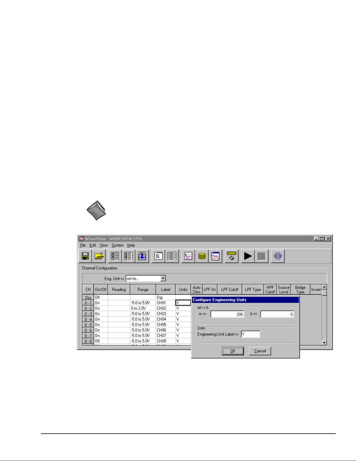
If connecting only one WBK61/62, connect the green
3.
4. Connect the input leads (CA-152) to the WBK61/62 Input HI and Input LO jacks.
5. Connect the test leads (CA-152) to the circuit under test. You may use alligator clips (CN-109) to
If desired, set the applicable WaveBook channel(s) to the appropriate scale by setting the mx+b function in
the WaveView program as discussed in the following section Software Setup.
Software Setup
Depending on your application, you will need to set several software parameters so that WaveView will
organize data to your requirements. Of special importance is the correct setting of the scaling factor. This
is done using the mx + b equation.
banana plug/alligator clip
lead (CN-111) from
the WBK61/62 earth ground connector to the local earth ground.
If connecting two or more WBK61/62s, connect the green banana plug/alligator clip lead (CN-111)
from the
last
WBK61/62 earth ground connector to the local earth ground. Refer also to step 2 and the
above figure.
connect test leads.
To configure units for WBK61 and WBK62, you must use the
Configure Engineering Units
dialog box to
ensure units are correctly scaled. This is done as follows:
1. Left-click on the Units column (in WaveView’s main window).
2. Select mx + b in the Units box. The Configure Engineering Units dialog box will appear.
3. For WBK61: set m to 200
For WBK62: set m to 20
Reference Note:
For detailed software setup information, refer to the “Software Setup” in chapter 2.
For detailed WaveView information, refer to chapter 5.
Note: The Configuration Engineering Units dialog box (above figure) shows m set to 200.
This is the setting needed to ensure accurate scaling for WBK61 applications.
If using WBK62, m would be set to a value of 20.
WaveBook User’s Manual,
ch03Dn 6-21-99
WaveView Main Window, with Configure Engineering Units Dialog Box
WBK Expansion Options 3-51
Page 84

Software Function
If you intend to write your own computer programs, refer to the WaveBook Programmer’s Manual as
needed. Note that the API does not contain functions specific to WBK61 or WBK62.
WBK61/62 - Specifications
Specifications are provided in Appendix A.
3-52 WBK Expansion Options,
ch03Dn 6-21-99
WaveBook User’s Manual
Page 85

System Power & Assembly 4
Power Management…… 4-1
Calculating the System Power Requirement…… 4-1
CA-115 & CA-116 Power Cable Connections…… 4-3
DBK30A - Rechargeable Battery Module…… 4-4
Hardware Setup…… 4-5
DBK30A - Specifications…… 4-6
DBK34 - Vehicle UPS Module…… 4-7
Hardware Setup…… 4-8
DBK34 - Specifications…… 4-9
Stacking Modules…… 4-10
Power Management
The power supplies that can be used with the WaveBook are listed in the following table.
WaveBook Product Power Supplies
Item Name/Description Capacity
TR-40U
DBK30A
DBK34
Other
AC Power Adapter (shipped with WaveBooks & WBK Modules) 90-264 VAC input;
2.50 A @ 15 VDC
Rechargeable Battery/Excitation Module (optional) 12-14 VDC, or 24-28 VDC
3.4 A-hr @ 14 VDC
Vehicle UPS (Uninterruptable Power Supply) Module (optional) 12 VDC, or 24 VDC
5.0 A-hr @ 12 VDC
10 to 30 VCD source, such as a car battery. Depends on source
Calculating the System Power Requirement
An incorrect use of power can damage equipment or affect performance.
It is important to supply your system with adequate, reliable power. For this reason, you need to know your
system’s power requirement. Computing power use is also important when using batteries to power
modules, as you will need to know a safe runtime before recharging is required.
The following statements relate to system power. They should be reviewed before
proceeding.
• Higher voltages draw fewer Amps for the same power.
Remember: Watts = voltage x current (W = E*I).
• The TR-40U power adapter provides power that is sufficient for the WaveBooks
and WaveBook modules. You do not need to make power requirement calculations
unless you intend daisy-chaining units, or you have a critical battery runtime.
• When using a TR-40U power adapter in daisy-chain scenarios, you may need to use
an additional power source. This will certainly be true with systems that draw more
than 2.5 amps.
• Do not overload your power supplies.
• Current drawn from other sources, such as car batteries, can be estimated from the
following current requirements table.
CAUTION
CAUTION
CAUTIONCAUTION
The following table lists amperage requirements for WaveBook products. Use the current requirements and
worksheet tables to calculate your system’s total power requirement. Take the appropriate amperage values
from the first table to fill in the second table; and perform the indicated multiplication and addition
operations to calculate the amperage for all units in your system.
WaveBook User’s Manual,
6-21-99
System Power & Assembly 4-1
Page 86

WaveBook Product Current Requirements (in Amps)
Products and
Product Combinations
WaveBook/512 /512H (alone)
WaveBook/516 (alone)
WBK10/10H (alone)
WBK11
WBK12
WBK13
WBK14 (alone)
WBK15 (alone)
WBK15 (typical)*
WBK15 (max)**
WBK16 (no excitation)
WBK16 (full excitation)
*Typical with 8 voltage modules.
** Maximum load with 8 strain-gage modules.
You may need to consult power specifications for individual 5B modules and for any excitation currents required.
Worksheet for Power Requirements
Product Qty
WaveBook/512/512H
WaveBook/516
WBK10/10H
WBK11
WBK12
WBK13
WBK14
WBK15
WBK16
DBK30A
14 VDC
0.43 0.20 0.40
1.00 0.50 1.00
0.32 0.20 0.30
0.27 0.10 0.22
0.47 0.23 0.45
0.57 0.28 0.20
0.90 0.50 0.85
0.13 0.08 0.12
0.24 0.13 0.23
0.75 0.36 0.70
1.08 0.52 1.00
1.80 0.87 1.67
×
Amps
×=
×=
×=
×=
×=
×=
×=
×=
×=
Maximum
Amps
DBK30A
29 VDC
=
Totals
TR-40U
15 VDC
Input voltage to the system modules (WaveBook, WBK10/10H, WBK14, WBK15, and WBK16) must be
in the range of 10 to 30 VDC and can come from an AC-to-DC adapter or from a battery. System cards
(WBK11, WBK12, or WBK13) get power from their WaveBook or WBK10/10H expansion module.
Available AC-to-DC adapters include the TR-40U (supplied), which has an input of 90-264 VAC and an
output of 2.50 A @ 15 VDC.
Battery options include the DBK30A or other 10 to 30 VDC source such as a car battery. The DBK30A
provides 14 VDC and when fully-charged has a storage capacity of 3.4 A⋅hr; car batteries have much higher
capacities. The basic formula for battery life is:
Runtime (hr) = Battery capacity (A⋅⋅⋅⋅hr) / Current load (A)
Battery life and performance depend on various factors including battery type, condition, charge
level, and ambient temperature. Be sure you consider these factors, especially when runtime is a
critical.
4-2 System Power & Assembly WaveBook User’s Manual
Page 87

CA-115 & CA-116 Power Cable Connections
Multiple units running on a common power supply can be daisy-chained together with CA-115 power
cables.
The optional CA-116 power cable permits the system to be plugged into a vehicle’s cigarette lighter, for use
with the vehicle’s battery.
Daisy-Chain of Power, Signal Control, and Signal Expansion
The DC current source must be sufficient units that are daisy-chained for power.
The CA-115 cable and 5-pin DIN connector are rated at 5 Amps maximum load.
You can make your own cables for powering WaveBook and WBK option modules. The
following diagram shows the pinout for the DIN5 power connector:
Power input (or daisy-chain)
connector (female) on
WaveBook, WBK10, WBK14,
WBK15, WBK16, and DBK30A
View looking at rear of WaveBook
(from outside of the unit)
DIN5 Power Pinout
+10 to +30 V 4
+10 to +30 V 1
Return
2
5 No connection
3 Return
WaveBook User’s Manual,
6-21-99
Note: The CA-115 cable and 5-pin DIN connector are rated at 5 Amps maximum load.
System Power & Assembly 4-3
Page 88

DBK30A - Rechargeable Battery Module
DBK30A Front Panel
DBK30A contains two rechargeable nickel-cadmium batteries for use with WaveBook, expansion WBK
modules, and transducers. DBK30A shares the same base dimensions as other WaveBook products,
allowing for convenient stacking. Note that stacking can be easily accomplished with the included splice
plates, discussed on page 4-10.
The power adapter (included) converts AC power to 24 VDC for charging DBK30A’s two battery packs.
Automatic charging circuits recharge the internal batteries quickly and safely. The charged battery runtime
depends on the current load and mode of operation.
An internal slide switch (SW2) determines the unit’s mode. The two modes are:
•
14 VDC Mode (default)
• 28 VDC Mode.
You should check the power requirements of each component in your system, and then
verify that the power source can provide sufficient power to meet your runtime
requirements.
Fully charge DBK30A’s batteries before use.
14 VDC Mode (default)
This mode provides 14 VDC for 3.4 A-hr. The typical battery runtime is from 3 to 6 hours depending on the
load. Unless 28 VDC is required, the 14 VDC mode should be used in WaveBook and WBK applications,
Unless you need 28 V, leave the unit in the 14 VDC mode. Use of the 28 VDC mode results in
a lower runtime, as only one battery pack can be used for 14 VDC. When in the 14 VDC mode,
both packs are used in parallel, resulting in a longer runtime for the same application.
4-4 System Power & Assembly WaveBook User’s Manual
Page 89

28 VDC Mode
The 28 VDC mode actually provides
transmitters (1.7 A-hr) require 28 VDC. The battery run-time ranges from 1 to 6 hours, depending on
system configuration. In this mode, 14 VDC is used for unregulated bridge excitation (for bridgeconfigured sensors, such as load cells), and power to WBK expansion products.
Hardware Setup
Configuration
The only configuration option is the choice of modes (14 VDC, or 28 VDC). If you do not need 28 V, leave
SW2 in the default position.
Internal switch SW2 is located on the printed circuit board, near the front center of the unit. To change or
verify the mode:
1. Remove DBK30A’s cover by removing one screw and sliding the cover forward until it separates from
both
14 VDC
and
28 VDC. Loop currents for two-wire, 4-20 mA
Unless you need 28 V, leave the unit in the 14 VDC mode. Use of the 28 VDC mode results in
a lower runtime, as only one battery pack can be used for 14 VDC. When in the 14 VDC mode,
both packs are used in parallel, resulting in a longer runtime for the same application.
If you are using a pre-owned DBK30A, or are unsure of the mode selected, use the
following steps to check SW2’s position. Note that new units are always shipped with SW2
selected to the 14 VDC mode.
the module.
2. Look near the front center of the circuit board and locate slide switch SW2.
3. Check SW2’s selection. The silkscreen indicates the 14 and 28 VDC positions.
4. Change the selection, if required. If you do not need 28 V, SW2 should be in the default position
(14 VDC).
5. Replace the top cover, and secure with screw.
Power
Connection. The figure shows the pinout for the POWER OUT DIN5 connector.
The 28 V pin is only active in the 28 VDC mode; however, the 14 V pin is active
+14 V
regardless of the mode selected.
Cable CA-115 is included in the DBK30A package. The cable connects to
DIN5 Power Out
DBK30A’s POWER OUT connector and WaveBook’s POWER IN connector.
The cable can be used to daisy-chain a DBK30A unit to a WBK expansion module.
28 VDC Mode. The primary purpose of the 28 VDC mode is to provide power for external loop
transmitters. The hookup is simple, as shown below.
T/C
WaveBook
+
2-Wire
T/C XMTR
4-20 mA
250
N
Ω
GND
+28 V
WaveBook User’s Manual,
6-21-99
2-Wire
+
Flow XMTR
Connecting Loop Transmitters
4-20 mA
COM
250
N
Ω
System Power & Assembly 4-5
Page 90

Another use of the 28 VDC mode is to provide excitation for bridge-type sensors, such as load cells (strain
gages) and other devices that may be attached to 5B modules inside a WBK15.
Excitation voltage from DBK30A is not regulated by the unit, and must therefore be
regulated externally. For most load cells, excitation voltage should be regulated to 10 V.
Charging.
To charge the DBK30A batteries:
1. Connect the adapter to DBK30A’s POWER IN connector.
2. Plug the adapter into the AC power receptacle.
Note that the charge cycle will begin automatically whenever AC power is applied after an interruption.
The charge cycle will automatically end when the batteries are fully charged.
Charging DBK30A’s Batteries
3. To manually initiate a charge cycle, press the START CHARGE momentary rocker-arm switch. Note
that subsequent charge cycles applied to a fully-charged DBK30A will have no ill effect. The module
will sense the fully-charged status and revert to the trickle-charge state within a few minutes.
Three LEDs on the DBK30A provide status information on the charging process or the external load.
LED Indicators & Descriptions
POWER IN
BATTERY CHARGING
POWER OUT
Indicates the charger is connected to a source of AC power and to the battery module.
Steady Light - Indicates the battery is in the high-current (2 A) charge mode.
Flashing - One or two flashes at a time indicates the batteries are fully charged.
Indicates power is flowing out to an external device, such as a WaveBook product.
Periodically, fully discharge the DBK30A to inhibit “lazy chemistry” (memory) in the
nickel-cadmium cells. To manually discharge a battery pack, connect a WaveBook to
the pack and leave it powered-on until the indicator lights go out.
Use While Charging. Both operating modes are capable of powering the WaveBook products while being
charged; however, the charging current is reduced, and charging time is increased. If AC power is
interrupted, a new charge cycle will begin automatically when AC power returns.
Even with the AC adapter, the batteries will eventually discharge under a WaveBook
operating load. Charging DOES NOT BEGIN AUTOMATICALLY (except on powerup). You must manually initiate the next charge cycle. Do not expect a WaveBook
powered by a DBK30A to operate as an uninterruptable power supply.
Stacking Modules
Stacking can be accomplished with the included splice plates, discussed on page 4-10.
DBK30A – Specifications
Name/Function: Rechargeable Battery Module
Battery Type: Nickel-cadmium
Number of Battery Packs: 2
Battery Pack Configuration: 12 series-connected sub-C
cells
Output Voltage: 14.4 V or 28.8 V (depending on the
selected mode)
Output Fuses: 2 A
Battery Amp-Hours: 3.4 A-hr (1.7 A-hr/pack)
CAUTION
CAUTION
CAUTIONCAUTION
CAUTION
CAUTION
CAUTIONCAUTION
Charge Termination: Peak detection
Charge Time: 2 hours
Charging Voltage from Supplied AC Adapter: 22 to 26
VDC @ 2 A
AC Adapter Input: 95 to 265 VAC @ 47 to 63 Hz
Size: 221 mm × 285 mm × 35 mm
(11" × 8-1/2" × 1-3/8")
Weight: 2.4 kg (6 lb)
4-6 System Power & Assembly WaveBook User’s Manual
Page 91

DBK34 - Vehicle UPS Module
DBK34 Front Panel
The DBK34 can power a data acquisition system in portable and in-vehicle applications (from 12 VDC or
24 VDC systems). Power storage capacity is:
5 A-hr @ 12 VDC or, 2.5 A-hr @ 24 VDC
For reliable data acquisition in a vehicle, the DBK34 provides clean and consistent operating power for the
following instances:
•
Prior to engine/generator start.
• During engine start-up (battery sag due to the high-current demand of starter motor and solenoid).
• After engine turn off.
The DBK34 contains two sealed-lead rechargeable batteries and associated charging circuits and current
indicators. Typically, these batteries can last more than 500 full cycles and up to 10 years standby lifetime
at room temperature. Recharging is fast, and extreme temperature performance is good. The DBK34 can be
used with the LogBook, DaqBook, WaveBook, and related DBKs and WBKs. The unit’s rugged metal
package has a compatible 8×11” footprint for convenient stacking with Velcro tabs and optional splice
plates and handles for carrying.
Main and auxiliary power input comes from 12 or 24 VDC via a terminal block (TB1) on the unit’s front
panel. The voltage mode is configured with jumpers on TB1. Automatic charging circuits recharge the
internal batteries quickly and safely. The charged battery runtime will depend on the load and mode of
operation.
Note: Current protection is provided by four fuses. Two 8A fuses for the units internal batteries, one 8 A
fuse for an auxiliary (external) battery, and a 15 A fuse for a vehicle battery.
You can use a CA-172 cable to connect a vehicle battery (via a cigarette lighter) to the DBK34
terminal board. The cable is six feet long, contains a cigarette lighter adapter at one end, and
stripped leads (for terminal connection) at the other.
For trouble-free operation, you must fully charge the batteries before use.
WaveBook User’s Manual,
6-21-99
System Power & Assembly 4-7
Page 92

Hardware Setup
Configuration
DBK34’s screw terminals read from right to left when
viewed from the front panel (see figure).
For 12 Volt Operation:
(1) Remove jumper from terminals 8 and 7, if present.
(2) Use a jumper to short terminals 9 and 8
(3) Use a jumper to short terminals 7 and 6
DBK34’s Screw Terminal Board, TB1
For 24 Volt Operation:
(1) Remove jumpers from terminals 9 and 8, if present
(2) Remove jumpers from terminals 7 and 6, if present.
(3) Use a jumper to short terminals 8 and 7.
Power
Note: Refer to the above figure, as needed.
Power In (for vehicle main/auxiliary batteries, 12 or 24 VDC only). Connect main battery positive to
terminal 3 of TB1 and main negative to terminal 4. If an auxiliary battery is used, connect its positive to
terminal 1 and negative to terminal 2.
Power Out. The figure shows the pinout for the POWER OUT DIN5
connectors. The DBK34 package includes a short connecting cable to connect
to the powered device. This cable connects the POWER OUT connector on
the DBK34 to the POWER IN connector on the WaveBook, LogBook,
DaqBook, or WBK/DBK module.
3
-RTN
5
No connection
DBK34's DIN5 power output
connectors (2 sockets)
2
-RTN
Indicators. Three front-panel LED indicators provide power and charging status information.
LED Indicators & Descriptions
MAIN POWER
CHARGING
DISCHARGING
Lights when the DBK34 is connected to a live vehicle (main) battery.
Lights when internal batteries are being charged at a rate of 0.025 to 0.050 A or greater.
Lights when internal batteries are discharging at a rate of 0.025 to 0.050 A or greater.
Runtime. Approximate runtime under various loads can be computed from the storage capacity (5 A-hr in
12 V mode; 2.5 A-hr in 24 V mode) and the load (main unit and other DBKs). See section Power
Management at the beginning of this chapter. Factory testing determined the following run-times:
+24V/+12V
1
+24V/+12V
4
Run-times & Load Conditions
240 minutes
190 minutes
120 minutes
DBK34 with 1.20 watt external load @ 23°C
DBK34 with 2.34 watt external load @ 23°C
DBK34 with 6.79 watt external load @ 23°C
Charging. In general, lead-acid batteries require charging at 120% of drain energy (for example, the 5 A-hr
DBK34 requires a charge equal to or greater than 6 A-hr). Charging time varies but is typically 4 to 5 hours
at 14 V for a totally empty battery.
CAUTION
CAUTION
CAUTIONCAUTION
Voltage applied to charge a DBK34 must not exceed 15 VDC in 12 V mode or 30 VDC
in 24 V mode. If not charging from the vehicle, a generic auto-battery charger (3 A) in
12-V mode is recommended.
CAUTION
CAUTION
CAUTIONCAUTION
Environmental Concern. DBK34’s lead batteries contain toxic materials
(Pb and H
). After the battery’s life cycle is over (up to 500 full cycles,
2SO4
or 5-10 years of use), sealed-lead batteries must be properly discarded, or recycled.
4-8 System Power & Assembly WaveBook User’s Manual
Page 93

Stacking Modules
Stacking can accomplished with the included splice plates, discussed on page 4-10.
DBK34 - Specifications
Name/Function: Vehicle UPS Module
Battery Type: Sealed-lead rechargeable
Number of Battery Packs: 2
Battery Pack Configuration: 6 series-connected D cells
Output Voltage: 12 V or 24 V (depending on jumpers)
Output Fuses: 8 A on each internal battery (2)
Input Fuses: 8 A for auxiliary battery,
Battery Capacity (Amp-Hours):
5 A-hr in 12 V mode (parallel)
2.5 A-hr in 24 V mode (series)
Operating Temperature: -20°F to 122°F (-29°C to 50°C)
Size: 8½ × 11 × 1¾ in. ( 216 × 279 × 44 mm)
Weight: 7.2 lb (3.27 kg)
15 A for vehicle battery
WaveBook User’s Manual,
6-21-99
System Power & Assembly 4-9
Page 94

Stacking Modules
Attaching Splice Plates to a WaveBook and two WBK Modules (the handle is optional)
WBK10/10H, WBK14, WBK15, and WBK16 are shipped with a splice plate kit. Each kit includes two
metal plates that screw onto the sides of stacked modules. The plates provide a means of stacking modules
to create one rigid assembly. Optional handles can be attached to the splice plates, if desired.
Note:
Splice plates will partially block the vents on WBK16s and WaveBook/516s when stacked.
This partial blocking of vents does not jeopardize the cooling process.
4-10 System Power & Assembly WaveBook User’s Manual
Page 95

WaveView 5
Introduction…… 5-1
Software Startup & Sample
WaveView Configuration Main
Acquisition Configuration…… 5-11
Introduction
WaveView is a graphical Windows-based program for use in WaveBook applications. The program allows
users to acquire data for immediate viewing or for storage to the PC's hard disk. No programming
knowledge is required by the user.
From WaveView you can:
Expanded Acuisition Features,
WaveBook/516 Only…… 5-13
Acquisition…… 5-2
Startup WaveView…… 5-2
Configure Channels…… 5-3
Configure Acquisition…… 5-4
Collect Data…… 5-5
Store Data…… 5-6
Window…… 5-6
Menu Items & Buttons…… 5-6
File…… 5-7
Edit…… 5-7
View…… 5-7
System…… 5-7
Input Channel Configuration…… 5-9
General Information ….. 5-11
Trigger Types ….. 5-11
•
Set up all analog or digital input parameters.
•
Acquire and save data to disk.
•
View the acquisition in real-time.
•
Send data to other Windows applications, such as spreadsheets and databases.
•
Launch PostView (an independent application) and view waveforms that were recorded by WaveView.
PostView is discussed in chapter 6.
External Clock and Counter-Timer …… 5-13
Digital Pattern Trigger…… 5-13
Pulse Trigger …… 5-14
WaveView Scope Window…… 5-15
Menu Items & Buttons…… 5-16
File…… 5-16
Acquire…… 5-16
Charts…… 5-16
Options…… 5-16
Window…… 5-16
Scope Display…… 5-17
WaveView Direct-To-Disk Window… 5-18
File…… 5-18
Acquire…… 5-18
Window…… 5-19
Data Destination Area…… 5-19
Item Description Item Description
1 Save Configuration 8 Open Scope Window
2 Load Configuration 9 Open Direct to Disk
3 Turn All Channels Off 10 Launch PostView with Latest Acquisition File
4 Turn All Channels On 11 Auto Zero Enabled Channels
5 Fill Down 12 Enable Spreadsheet Reading Column
6 Open Acquisition Configuration Dialog 13 Disable Spreadsheet Reading Column
7 Open Module Configuration Dialog 14 Open WBK16 Sensor Calibration Window
WaveBook User’s Manual,
6-24-99
WaveView Configuration Main Window
WaveView 5-1
Page 96

Software Startup & Sample Acquisition
The program installation CD-ROM contains both a 16-bit and a 32-bit version of WaveView. The figures in
this chapter reflect the 32-bit version, only. Note that the16-bit version has fewer toolbar buttons and
exhibits minor screen differences.
Startup WaveView
Start WaveView by double-clicking on its icon. WaveView holds user-configured parameters that can be
saved to disk. The default configuration filename is
the working directory for this configuration file. One of the following 5 situations will occur:
• If the default configuration file is found, all the required setup information is extracted from it, and
the application’s main window opens.
• If the default configuration file is not found, WaveView attempts to connect with WaveBook using
the following default parameters: Printer Port LPT1, Interrupt Level 7, and 4-bit Standard Protocol. If
this fails, the program tries LPT2 and Interrupt Level 5.
• If connection is established, WaveView’s main window opens.
• If the above fail, a dialog box appears, providing you with certain options. These are: Retry, Select
Device, Load File, and Exit.
WAVEVIEW.CFG
. When WaveView starts up, it searches
WaveView StartUp Box
• If no user-configuration file is found, or if no communication established, a dialog box prompts you
to choose an actual WaveBook from the device inventory, or to select a simulated device.
Select Device Box
Simulated WaveBook. If the hardware is not available, or if you just want to practice using the software,
select Simulated Device. The Simulated Device allows you to run various software functions with no
hardware concerns.
WaveBook Attached. If the WaveBook hardware is connected and switched on, select the applicable
WaveBook device. Then click on the Properties button to view the Device Properties screen (see following
figure).
5-2 WaveView,
6-24-99
WaveBook User’s Manual
Page 97

After you have selected the device parameters, click Close.
WaveView attempts to find the WaveBook at the specified port. One of the following situations will occur:
• The hardware is found, the WaveView main window opens.
• The hardware is not found, a dialog box informs you and provides another chance to select
parameters.
WaveView interrogates the hardware after it starts up to see what options and expansion modules are
actually connected to the WaveBook. The number of channels (shown on the configuration menu)
represents the number of channels actually connected to WaveBook.
Configure Channels
You can use the Simulated mode to become familiar with WaveView’s main features. The Simulated mode
is convenient, as there are no hardware concerns when using it. To select the simulated mode:
1. Select the System pull-down menu.
2. Select Simulated WaveBook.
Devices Properties
If WaveView cannot identify the hardware, and you have verified that the selected hardware
parameters are correct, exit WaveView and then use the “Test Hardware” feature of the
Daq Configuration control panel. A discussion of this feature begins on page 2-6.
• On/Off Column. To acquire data with WaveView, channels must be properly connected to signal
WaveBook User’s Manual,
Configuring Channels from WaveView’s Main Window
sources, and must be enabled (On). Channels can be enabled as folows:
(1) Click in a channel’s On/Off cell, then select "On" from the drop-down menu (that appears above the
range column), or
(2) Double-click in a channel’s On/Off cell to toggle to “On.” Note that the on/off status will change
with each double-click, or
(3) Click on the toolbar’s “On” button to turn All channels on. Note that the “Off” button turns all
channels off.
6-24-99
WaveView 5-3
Page 98
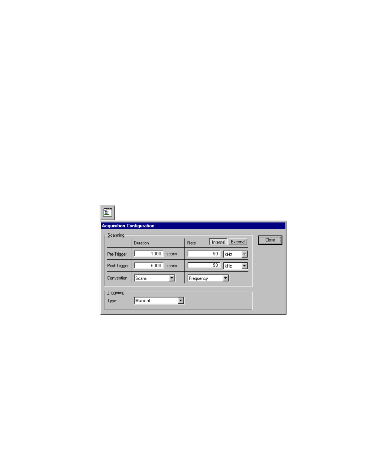
• Reading Column. Not user configurable. This column displays values of enabled channels.
• Range Column. Select a channel’s range in one of two ways.
(1) Click in a channel’s Range cell, then select the desired range from the drop-down menu.
(2) Continue to double-click in the applicable channel’s Range cell to cycle through the available
ranges. Stop double-clicking when the desired range is indicated.
• Label Column. Channels have default labels, such as CH05. You can change the label by clicking on
the cell, then typing in the new label. Labels must be unique, i.e., each channel must have its own
label. Attempts to use duplicate labels, or use no label will result in a warning message.
• Units Column. Select a channel’s units in one of two ways.
(1) Click in a channel’s Units cell, then select the desired units from the pull-down menu.
(2) Double-click in a channel’s Units cell to cycle through the units. Note that when the mX+b dialog
box appears you need to click “OK” to continue cycling.
Note: You can use the mX+b equation to adjust a channel’s scale and offset. You can enter
Configure Acquisition
The following text describes how to configure an acquisition.
After completing channel configuration, select the Acquisition Configuration option from the View menu or
from the tool bar. The following figure represents the Acquisition Configuration dialog box, and its related
toolbar button. The parameters shown are a result of the values entered below.
user-defined units from the mX+b dialog box.
5-4 WaveView,
Acquisition Configuration Dialog Box
Trigger
Trigger Source: Manual
Duration.
Convention: Scans
pre-trigger scans: 1000
post-trigger scans: 5000
Rate.
Convention: Frequency
pre-trigger: 50 kHz
post-trigger scans: 50 kHz
Press the Close button to complete the acquisition configuration.
6-24-99
WaveBook User’s Manual
Page 99

Collect Data
The following text describes how to collect data for a sample acquisition.
Now you are ready to read data from the WaveBook (or Simulated WaveBook). Select the Scope option
from the View menu or from the tool menu. The Scope window will display. Complete the acquisition setup
as follows:
• Number of Charts. First, the Scope window should be configured to display 4 charts since 4 channels
were previously selected for the acquisition. Select the Number of Charts option from the Charts menu
item. When the flyout appears showing a selection of up to 8 channels for display, click on 4.
• One Shot or Continuous. The system is now set to start collecting data. At this point, you may acquire
one acquisition (One Shot) or continuous acquisitions (Continuous). For this sample acquisition, click
on the Acquire One Shot button, then click the Manual Trigger button.
• Data Acquisition. The system has now collected 1000 pre-trigger scans and 5000 post-trigger scans.
If desired, you may modify the current Scope window display as follows:
•
View additional channels (up to 8) simultaneously by changing the entry in the Number of Charts
menu. The next figure displays two channels in the WaveView Scope window.
•
Change the channels viewed. Use the channel select list box at the right of the waveforms to display
waveforms of other active channels.
• To scale the waveforms, click on the Scale All Charts button. All 4 waveforms should then be visible.
• Examine the waveforms at any point along the timeline by using the horizontal scroll-bar.
• Vary the number of scans displayed by using the Zoom In or Zoom Out buttons.
Item Description Item Description
WaveBook User’s Manual,
WaveView Scope Button and Window
1 Save Data 7 Zoom In
2 Acquire Auto-Rearm 8 Zoom Out
3 Acquire One Shot 9 Scale All Charts
4 Stop After Acquisition Complete 10 Toggle Cross Hairs
5 Stop Immediately 11 Toggle Grids
6 Manual Trigger 12 Open Configuration Window
6-24-99
WaveView 5-5
Page 100
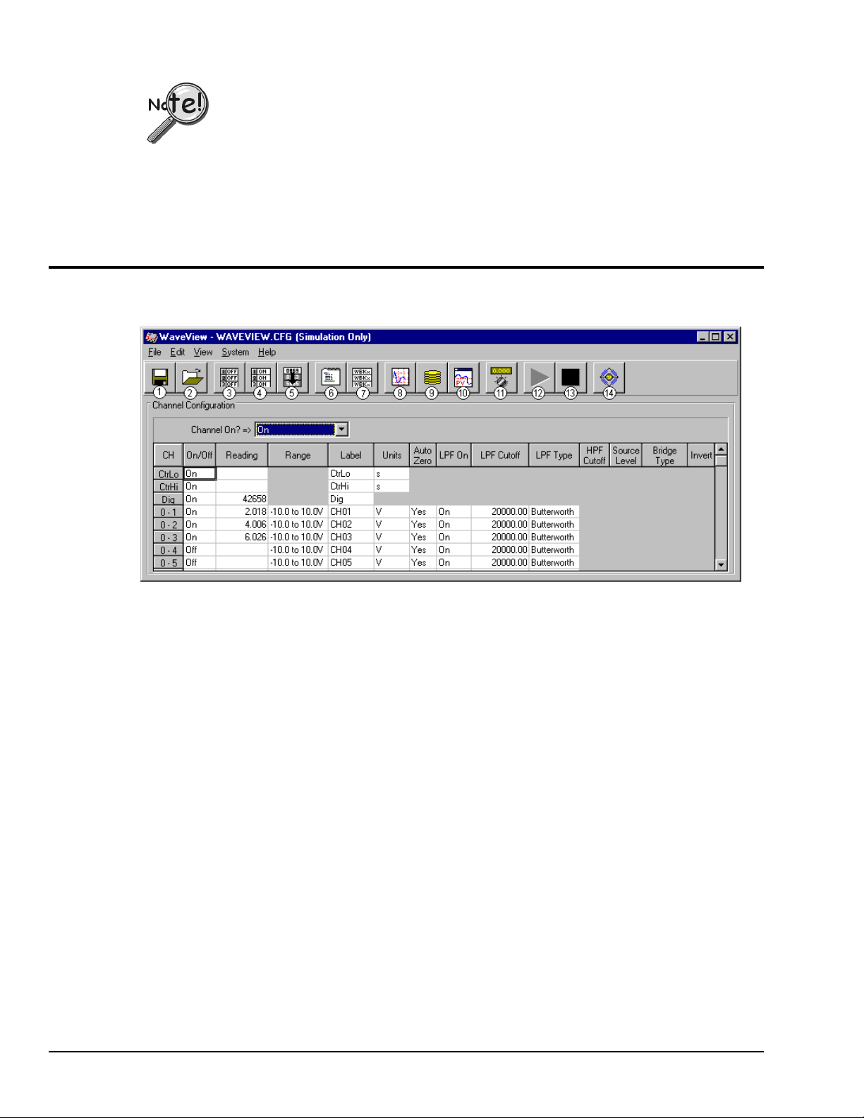
Store Data (
and use PostView, optional
)
Data to be used in PostView must be in ASCII (.txt) or PostView Binary (.iot) format.
From WaveView, you can select the PostView Binary format by navigating as follows:
System
WaveView Main Window
⇒⇒⇒⇒
Save collected data to disk by clicking on the Save As button ("floppy disk" or left-most button), and then
giving the file a name. Note that you can analyze the saved data with PostView, a post-acquisition data-
viewer program.
To open PostView, return to the WaveView Configuration main window. You may select the PostView
option from the View menu, or click on the PostView button (button 10) from the toolbar. Refer to
chapter 6 for detailed PostView information.
WaveView Configuration Main Window
The following figure shows a sample of the WaveView Configuration main window.
Options
⇒⇒⇒⇒
Data Files tab.
⇒⇒⇒⇒
Item Description Item Description
1 Save Configuration 8 Open Scope Window
2 Load Configuration 9 Open Direct to Disk
3 Turn All Channels Off 10 Launch PostView with Latest Acquisition File
4 Turn All Channels On 11 Auto Zero Enabled Channels
5 Fill Down 12 Enable Spreadsheet Reading Column
6 Open Acquisition Configuration Dialog 13 Disable Spreadsheet Reading Column
7 Open Module Configuration Dialog 14 Open WBK16 Sensor Calibration Window
WaveView interrogates the hardware after it starts up to see what options and expansion modules are
actually connected to the WaveBook. The number of channels displayed on the configuration menu
corresponds to all the channels connected.
Menu Items & Buttons
WaveView functions are initiated through toolbar buttons and pull-down menu selections. The toolbar
buttons are identified in the above figure. In the following sections, menu functions are explained in order
of the menu structure.
Note: The following menu descriptions also apply to corresponding toolbar buttons, when applicable. Not
all menu items have a corresponding tool button.
WaveView Configuration Main Window
5-6 WaveView,
6-24-99
WaveBook User’s Manual
 Loading...