

Measurement USB-TC-AI User Manual

USB-PDISO8
USB-based
Isolated Input and Relay Output
User's Guide
Document Revision 4, August, 2006
© Copyright 2006, Measurement Computing Corporation™

Your new Measurement Computing product comes with a fantastic extra —
Management committed to your satisfaction!
Thank you for choosing a Measurement Computing product—and congratulations! You own the finest, and you can now enjoy
the protection of the most comprehensive warranties and unmatched phone tech support. It’s the embodiment of our mission:
To provide data acquisition hardware and software that will save time and save money.
Simple installations minimize the time between setting up your system and actually making measurements. We offer quick and
simple access to outstanding live FREE technical support to help integrate MCC products into a DAQ system.
Limited Lifetime Warranty: Most MCC products are covered by a limited lifetime warranty against defects in materials or
workmanship for the life of the product, to the original purchaser, unless otherwise noted. Any products found to be defective in
material or workmanship will be repaired, replaced with same or similar device, or refunded at MCC’s discretion. For specific
information, please refer to the terms and conditions of sale.
Harsh Environment Program: Any Measurement Computing product that is damaged due to misuse, or any reason, may be
eligible for replacement with the same or similar device for 50% of the current list price. I/O boards face some harsh
environments, some harsher than the boards are designed to withstand. Contact MCC to determine your product’s eligibility for
this program.
30 Day Money-Back Guarantee: Any Measurement Computing Corporation product may be returned within 30 days of
purchase for a full refund of the price paid for the product being returned. If you are not satisfied, or chose the wrong product by
mistake, you do not have to keep it.
These warranties are in lieu of all other warranties, expressed or implied, including any implied warranty of merchantability or
fitness for a particular application. The remedies provided herein are the buyer’s sole and exclusive remedies. Neither
Measurement Computing Corporation, nor its employees shall be liable for any direct or indirect, special, incidental or
consequential damage arising from the use of its products, even if Measurement Computing Corporation has been notified in
advance of the possibility of such damages.
Trademark and Copyright Information
Measurement Computing Corporation, InstaCal, Universal Library, and the Measurement Computing logo are either trademarks
or registered trademarks of Measurement Computing Corporation. Refer to the Copyrights & Trademarks section on
mccdaq.com/legal for more information about Measurement Computing trademarks. Other product and company names
mentioned herein are trademarks or trade names of their respective companies.
© 2006 Measurement Computing Corporation. All rights reserved. No part of this publication may be reproduced, stored in a
retrieval system, or transmitted, in any form by any means, electronic, mechanical, by photocopying, recording, or otherwise
without the prior written permission of Measurement Computing Corporation.
Notice
Measurement Computing Corporation does not authorize any Measurement Computing Corporation product for use
in life support systems and/or devices without prior written consent from Measurement Computing Corporation.
Life support devices/systems are devices or systems that, a) are intended for surgical implantation into the body, or
b) support or sustain life and whose failure to perform can be reasonably expected to result in injury. Measurement
Computing Corporation products are not designed with the components required, and are not subject to the testing
required to ensure a level of reliability suitable for the treatment and diagnosis of people.
HM USB-PDISO8.doc
iii

Table of Contents
About this User's Guide .......................................................................................................................v
What you will learn from this user's guide .........................................................................................................v
Conventions in this user's guide .........................................................................................................................v
Where to find more information.........................................................................................................................v
Chapter 1
Introducing the USB-PDISO8........................................................................................................... 1-1
Software features............................................................................................................................................ 1-1
USB-PDISO8 block diagram.......................................................................................................................... 1-2
Connecting a USB-PDISO8 to your computer is easy ................................................................................... 1-2
Chapter 2
Installing the USB-PDISO8............................................................................................................... 2-1
What comes with your USB-PDISO8 shipment? ........................................................................................... 2-1
Hardware ....................................................................................................................................................................... 2-1
Additional documentation.............................................................................................................................................. 2-2
Unpacking the USB-PDISO8 ......................................................................................................................... 2-2
Installing the software .................................................................................................................................... 2-2
Installing the USB-PDISO8............................................................................................................................ 2-2
Connecting the external power supply........................................................................................................................... 2-2
Connecting the USB-PDISO8 to your system ............................................................................................................... 2-3
Chapter 3
Functional Details ............................................................................................................................. 3-1
Internal components ....................................................................................................................................... 3-1
Direct current (dc) power connector and +9 V power supply ........................................................................................ 3-1
USB OUT connector...................................................................................................................................................... 3-2
USB IN connector.......................................................................................................................................................... 3-2
External power connectors............................................................................................................................................. 3-2
USB LED....................................................................................................................................................................... 3-2
PWR LED...................................................................................................................................................................... 3-2
Screw terminals and relays ............................................................................................................................................3-3
Main connector and pin out............................................................................................................................ 3-3
Relay contact terminals (0 - NC, C, N0 through 7- NC, C, N0)..................................................................................... 3-4
Differential isolated digital input terminals (IP0A to IP7B) ..........................................................................................3-5
Daisy chaining additional modules to the USB-PDISO8 ............................................................................... 3-6
Power limitations using multiple USB-PDISO8 devices................................................................................ 3-7
Supply current................................................................................................................................................................ 3-7
Voltage drop ..................................................................................................................................................................3-7
Relay contact protection circuit for inductive loads....................................................................................................... 3-8
Chapter 4
Specifications.................................................................................................................................... 4-1
Relay specification ......................................................................................................................................... 4-1
Isolated inputs................................................................................................................................................. 4-1
Power.............................................................................................................................................................. 4-2
USB specifications ......................................................................................................................................... 4-2
Mechanical ..................................................................................................................................................... 4-3
Environmental ................................................................................................................................................ 4-3
Main connector............................................................................................................................................... 4-3
Screw terminal pinouts ................................................................................................................................... 4-3
iv

Preface
About this User's Guide
What you will learn from this user's guide
This user's guide explains how to install, configure, and use the USB-PDISO8 so that you get the most out of its
USB-based isolated input/relay output features.
This user's guide also refers you to related documents available on our web site, and to technical support
resources.
Conventions in this user's guide
For more information on …
Text presented in a box signifies additional information and helpful hints related to the subject matter you are
reading.
Caution! Shaded caution statements present information to help you avoid injuring yourself and others,
damaging your hardware, or losing your data.
<#:#> Angle brackets that enclose numbers separated by a colon signify a range of numbers, such as those assigned
to registers, bit settings, etc.
bold text Bold text is used for the names of objects on the screen, such as buttons, text boxes, and check boxes. For
example:
1. Insert the disk or CD and click the OK button.
italic text Italic text is used for the names of manuals and help topic titles, and to emphasize a word or phrase. For
example:
The InstaCal installation procedure is explained in the Quick Start Guide.
Never touch the exposed pins or circuit connections on the board.
Where to find more information
The following electronic documents provide information that can help you get the most out of your USBPDISO8.
MCC's Specifications: USB-PDISO8 (the PDF version of the Specifications chapter in this guide) is
available on our web site at www.mccdaq.com/pdfs/USB-PDISO8.pdf
MCC's Quick Start Guide is available on our web site at
www.mccdaq.com/PDFmanuals/DAQ-Software-Quick-Start.pdf
MCC's Guide to Signal Connections is available on our web site at
www.mccdaq.com/signals/signals.pdf
MCC's Universal Library User's Guide is available on our web site at
www.mccdaq.com/PDFmanuals/sm-ul-user-guide.pdf
MCC's Universal Library Function Reference is available on our web site at
www.mccdaq.com/PDFmanuals/sm-ul-functions.pdf
MCC's Universal Library for LabVIEW
www.mccdaq.com/PDFmanuals/SM-UL-LabVIEW.pdf
.
.
™
User’s Guide is available on our web site at
.
.
.
.
USB-PDISO8 User's Guide (this document) is also available on our web site at
www.mccdaq.com/PDFmanuals/USB-PDISO8.pdf
.
v
Chapter 1
Introducing the USB-PDISO8
This user's guide contains all of the information you need to install, configure, and program the USB-PDISO8.
The USB-PDISO8 is a USB 1.1 low-speed device that is used for data acquisition and control. It is designed for
USB 1.1 ports, and was tested for full compatibility with both USB 1.1 and USB 2.0 ports. The USB-PDISO8 is
supported under popular Microsoft
The USB-PDISO8 offers eight single pole double throw (SPDT) Form C relay outputs and eight isolated high
voltage digital inputs. The inputs monitor 24V AC or DC inputs. The relay outputs provide 6 Amp outputs at
240 VAC or 28 VDC.
You can configure each isolated input with an optional input filter. The input filters are enabled and disabled by
software.
All I/O connections are made to two sets of screw terminals.
The USB-PDISO8 is powered by an external 9 V, 1 A regulated power supply that is shipped with the device.
The USB-PDISO8 is shipped in a rugged enclosure that you can mount on a DIN rail or on a bench.
®
Windows® operating systems.
Software features
For information on the features of InstaCal and the other software included with your USB-PDISO8, refer to the
Quick Start Guide that shipped with your device. The Quick Start Guide is also available in PDF at
www.mccdaq.com/PDFmanuals/DAQ-Software-Quick-Start.pdf
Check www.mccdaq.com/download.htm
under less commonly used operating systems.
for the latest software version or versions of the software supported
1-1
.
USB-PDISO8 User's Guide Introducing the USB-PDISO8
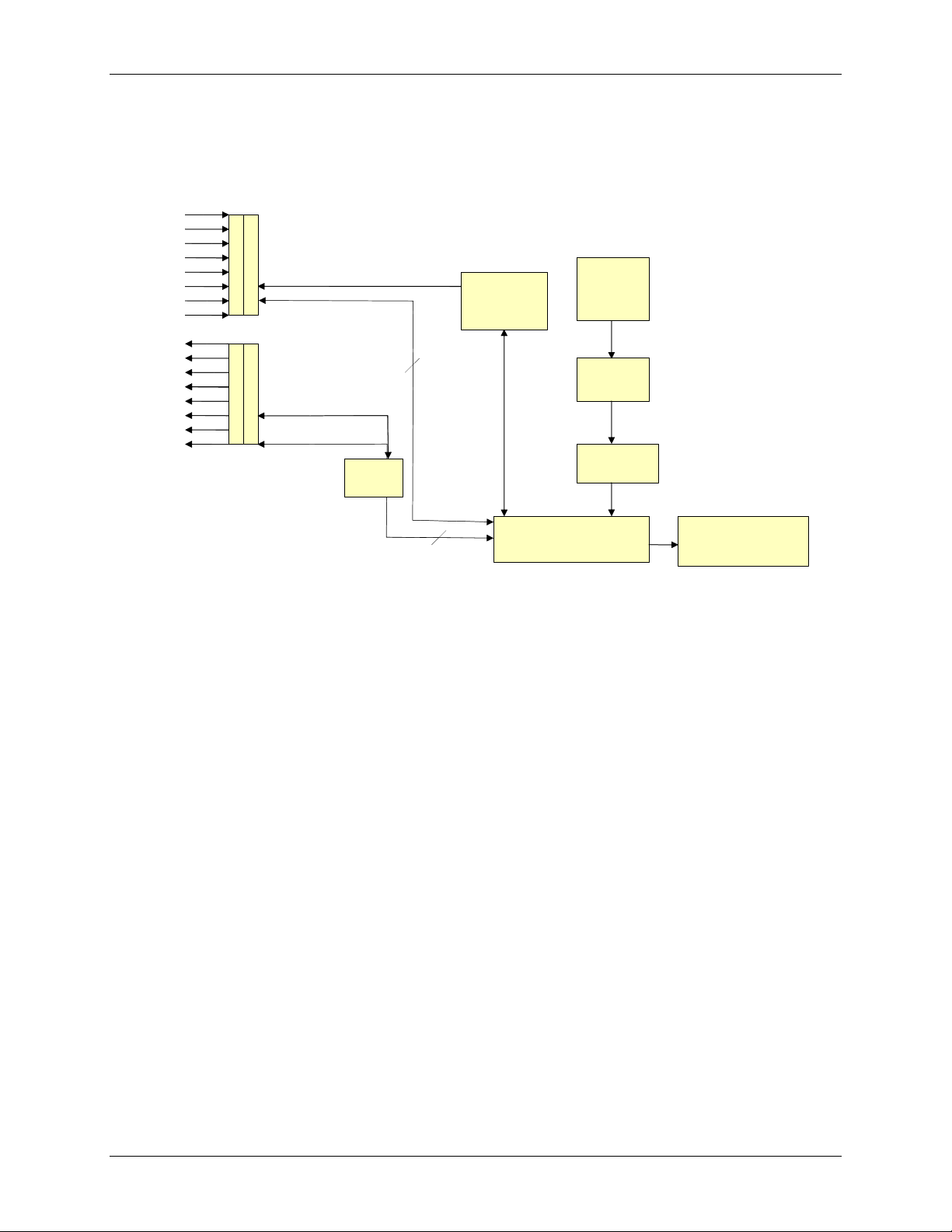
USB-PDISO8 block diagram
USB-PDISO8 functions are illustrated in the block diagram shown here.
Differential
isolated inputs
Form C
Relay outputs
Control
Inputs 0 to 7
8
C
Lo
Control
Relays 0 to 7
CHi
Relay
Driver
Control
Registers
8
9 V
Nominal
External
Power
Power
Monitor
Power
Regulator
USB
Controller
500 mA
USB 2.0-compliant
interface
Figure 1-1. USB-PDISO8 functional block diagram
Connecting a USB-PDISO8 to your computer is easy
Installing a data acquisition device has never been easier.
The USB-PDISO8 relies upon the Microsoft Human Interface Device (HID) class drivers. The HID class
drivers ship with every copy of Windows that is designed to work with USB ports. We use the Microsoft
HID because it is a standard, and its performance delivers full control and maximizes data transfer rates for
your USB-PDISO8. No third-party device driver is required.
The USB-PDISO8 is plug-and-play. There are no jumpers to position, DIP switches to set, or interrupts to
configure.
You can connect the USB-PDISO8 before or after you install the software, and without powering down
your computer first. When you connect an HID to your system, your computer automatically detects it and
configures the necessary software. You can connect and power multiple HID peripherals to your system
using a USB hub.
You can connect your system to various devices using a standard four-wire cable. The USB connector
replaces the serial and parallel port connectors with one standardized plug and port combination.
Data can flow two ways between a computer and peripheral over USB connections.
Make sure that you have the latest Windows Updates installed for your USB driver, particularly "XP Hotfix
KB822603."
1-2
 Loading...