

Page 1
Page 2

USB-3101FS
Analog Voltage Output
User's Guide
Document Revision 1, November, 2008
© Copyright 2008, Measurement Computing Corporation
Page 3

HM USB-3101FS.docx
Your new Measurement Computing product comes with a fantastic extra —
Management committed to your satisfaction!
Refer to www.mccdaq.com/execteam.html for the names, titles, and contact information of each key executive at Measurement
Computing.
Thank you for choosing a Measurement Computing product—and congratulations! You own the finest, and you can now enjoy
the protection of the most comprehensive warranties and unmatched phone tech support. It’s the embodiment of our mission:
To provide PC-based data acquisition hardware and software that will save time and save money.
Simple installations minimize the time between setting up your system and actually making measurements. We offer quick and
simple access to outstanding live FREE technical support to help integrate MCC products into a DAQ system.
Limited Lifetime Warranty: Most MCC products are covered by a limited lifetime warranty against defects in materials or
workmanship for the life of the product, to the original purchaser, unless otherwise noted. Any products found to be defective in
material or workmanship will be repaired, replaced with same or similar device, or refunded at MCC’s discretion. For specific
information, please refer to the terms and conditions of sale.
Harsh Environment Warranty® Program: Any Measurement Computing product that is damaged due to misuse, or any
reason, may be eligible for replacement with the same or similar device for 50% of the current list price. I/O boards face some
harsh environments, some harsher than the boards are designed to withstand. Contact MCC to determine your product’s
eligibility for this program
30 Day Money-Back Guarantee: Any Measurement Computing Corporation product may be returned within 30 days of
purchase for a full refund of the price paid for the product being returned. If you are not satisfied, or chose the wrong product by
mistake, you do not have to keep it.
These warranties are in lieu of all other warranties, expressed or implied, including any implied warranty of merchantability or
fitness for a particular application. The remedies provided herein are the buyer’s sole and exclusive remedies. Neither
Measurement Computing Corporation, nor its employees shall be liable for any direct or indirect, special, incidental or
consequential damage arising from the use of its products, even if Measurement Computing Corporation has been notified in
advance of the possibility of such damages.
3
Page 4

Trademark and Copyright Information
TracerDAQ, Universal Library, Harsh Environment Warranty, Measurement Computing Corporation, and the Measurement
Computing logo are either trademarks or registered trademarks of Measurement Computing Corporation.
Windows, Microsoft, and Visual Studio are either trademarks or registered trademarks of Microsoft Corporation
LabVIEW is a trademark of National Instruments.
CompactFlash is a registered trademark of SanDisk Corporation.
XBee and XBee-PRO are trademarks of MaxStream, Inc.
All other trademarks are the property of their respective owners.
Information furnished by Measurement Computing Corporation is believed to be accurate and reliable. However, no
responsibility is assumed by Measurement Computing Corporation neither for its use; nor for any infringements of patents or
other rights of third parties, which may result from its use. No license is granted by implication or otherwise under any patent or
copyrights of Measurement Computing Corporation.
All rights reserved. No part of this publication may be reproduced, stored in a retrieval system, or transmitted, in any form by any
means, electronic, mechanical, by photocopying, recording, or otherwise without the prior written permission of Measurement
Computing Corporation.
Notice
Measurement Computing Corporation does not authorize any Measurement Computing Corporation product for use
in life support systems and/or devices without prior written consent from Measurement Computing Corporation.
Life support devices/systems are devices or systems which, a) are intended for surgical implantation into the body,
or b) support or sustain life and whose failure to perform can be reasonably expected to result in injury.
Measurement Computing Corporation products are not designed with the components required, and are not subject
to the testing required to ensure a level of reliability suitable for the treatment and diagnosis of people.
4
Page 5

Table of Contents
Preface
About this User's Guide ....................................................................................................................... 6
What you will learn from this user's guide ......................................................................................................... 6
Conventions in this user's guide ........................................................................................................................................ 6
Where to find more information ......................................................................................................................... 6
Safety guidelines ................................................................................................................................................ 7
Chapter 1
Introducing the USB-3101FS................................................................................................................ 8
Overview: USB-3101FS features ....................................................................................................................... 8
USB-3101FS block diagram .............................................................................................................................. 8
Software features ................................................................................................................................................ 8
Chapter 2
Installing the USB-3101FS .................................................................................................................... 9
What comes with your USB-3101FS shipment? ................................................................................................ 9
Hardware .......................................................................................................................................................................... 9
Additional documentation ................................................................................................................................................. 9
Optional accessories ......................................................................................................................................................... 9
Unpacking the USB-3101FS .............................................................................................................................. 9
Installing the software ...................................................................................................................................... 10
Installing the hardware ..................................................................................................................................... 10
Calibrating the USB-3101FS ............................................................................................................................ 10
Chapter 3
Functional Details ............................................................................................................................... 11
Components ...................................................................................................................................................... 11
Screw terminals................................................................................................................................................................11
Analog outputs (AO 0 to AO 3) .......................................................................................................................................12
USB connector ................................................................................................................................ .................................12
LED .................................................................................................................................................................................12
Strain relief slot for USB cable ........................................................................................................................................12
High-voltage applications ................................................................................................................................. 12
Connecting a load ............................................................................................................................................. 12
Analog output circuitry ..................................................................................................................................... 13
Chapter 4
Specifications ...................................................................................................................................... 14
Analog output ................................................................................................................................................... 14
Accuracy ..........................................................................................................................................................................15
Power ................................................................................................................................................................ 15
Bus interface ..................................................................................................................................................... 15
Environmental .................................................................................................................................................. 15
Safety voltages .................................................................................................................................................. 16
Mechanical ....................................................................................................................................................... 16
Screw terminal connector ................................................................................................................................. 16
Accessory products ........................................................................................................................................... 16
Declaration of Conformity .................................................................................................................. 17
5
Page 6
Preface
About this User's Guide
What you will learn from this user's guide
This user's guide explains how to install, configure, and use the USB-3101FS so that you get the most out of its
analog output features.
This user's guide also refers you to related documents available on our web site, and to technical support
resources.
Conventions in this user's guide
For more information on …
Text presented in a box signifies additional information and helpful hints related to the subject matter you are
reading.
Caution! Shaded caution statements present information to help you avoid injuring yourself and others,
damaging your hardware, or losing your data.
< : > Angle brackets that enclose numbers separated by a colon signify a range of numbers, such as those assigned
to registers, bit settings, etc.
bold text Bold text is used for the names of objects on the screen, such as buttons, text boxes, and check boxes. For
example:
1. Insert the disk or CD and click the OK button.
italic text Italic text is used for the names of manuals and help topic titles, and to emphasize a word or phrase. For
example:
The InstaCal installation procedure is explained in the Quick Start Guide.
Never touch the exposed pins or circuit connections on the board.
Where to find more information
The following electronic documents provide helpful information relevant to the operation of the USB-3101FS.
MCC's Specifications: USB-3101FS (the PDF version of the Specifications chapter in this guide) is
available on our web site at www.mccdaq.com/pdfs/USB-3101FS.pdf.
MCC's Quick Start Guide is available on our web site at
www.mccdaq.com/PDFmanuals/DAQ-Software-Quick-Start.pdf.
MCC's Guide to Signal Connections is available on our web site at
www.mccdaq.com/signals/signals.pdf.
MCC's Universal Library User's Guide is available on our web site at
www.mccdaq.com/PDFmanuals/sm-ul-user-guide.pdf.
MCC's Universal Library Function Reference is available on our web site at
www.mccdaq.com/PDFmanuals/sm-ul-functions.pdf.
MCC's Universal Library for LabVIEW™ User’s Guide is available on our web site at
www.mccdaq.com/PDFmanuals/SM-UL-LabVIEW.pdf.
USB-3101FS User's Guide (this document) is also available on our web site at
www.mccdaq.com/PDFmanuals/USB-3101FS.pdf.
6
Page 7

USB-3101FS User's Guide
Safety guidelines
You can connect hazardous voltages to the USB-3101FS screw terminals. A hazardous voltage is a voltage
greater than 42.4 Vpk or 60 VDC to earth ground. Take the following precautions if you connect hazardous
voltages to the USB-3101FS:
Caution! Ensure that hazardous voltage wiring is performed only by qualified personnel adhering to local
electrical standards.
Caution! Do not mix hazardous voltage circuits and human-accessible circuits on the same device.
Caution! Make sure that devices and circuits connected to the USB-3101FS are properly insulated from
human contact.
Caution! When device terminals are hazardous voltage LIVE (>42.4Vpk/60 VDC), ensure that devices and
circuits connected to the USB-3101FS are properly insulated from human contact. Use the
ACC-107 backshell with 10-position connector block to ensure that the terminals are not
accessible.
7
Page 8

USB
Microcontroller
USB
Hi-Speed
USB 2.0
Compliant
Interface
USB
AO 0
COM
D/A0
Amplifier
Overvoltage
Short-circuit
Protection
Isolation barrier
Isolated
DAC
AO 1
COM
D/A1
Amplifier
Overvoltage
Short-circuit
Protection
Isolated
DAC
AO 2
COM
D/A2
Amplifier
Overvoltage
Short-circuit
Protection
Isolated
DAC
AO 3
COM
D/A3
Amplifier
Overvoltage
Short-circuit
Protection
Isolated
DAC
Chapter 1
Introducing the USB-3101FS
Overview: USB-3101FS features
This user's guide contains all of the information you need to connect the USB-3101FS to your computer and to
the signals you want to control.
The USB-3101FS is a USB 2.0 full-speed device that is supported under popular Microsoft® Windows®
operating systems. The USB-3101FS is fully compatible with both USB 1.1 and USB 2.0 ports.
The USB-3101FS is a 16-bit, 4-channel, 100 kS/s analog output device. The output range is ±10 V.
All signal connections are made to detachable screw terminals. The USB-3101FS is powered by the +5 volt
USB supply from your computer. No external power is required.
USB-3101FS block diagram
USB-3101FS functions are illustrated in the block diagram shown here.
Software features
For information on the features of InstaCal and the other software included with your USB-3101FS, refer to the
Quick Start Guide that shipped with your device. The Quick Start Guide is also available in PDF at
www.mccdaq.com/PDFmanuals/DAQ-Software-Quick-Start.pdf.
Check www.mccdaq.com/download.htm for the latest software version.
Figure 1. USB-3101FS functional block diagram
8
Page 9

Installing the USB-3101FS
What comes with your USB-3101FS shipment?
The following items are shipped with the USB-3101FS.
Hardware
USB-3101FS
USB cable (2 meter length)
Chapter 2
Additional documentation
In addition to this hardware user's guide, you should also receive the Quick Start Guide (available in PDF at
www.mccdaq.com/PDFmanuals/DAQ-Software-Quick-Start.pdf). This booklet supplies a brief description of
the software you received with your USB-3101FS and information regarding installation of that software.
Please read this booklet completely before installing any software or hardware.
Optional accessories
ACC-107 — backshell with 10-position connector block (quantity 1). Additional details are available on
our web site at www.mccdaq.com/cbicatalog/cbiproduct.asp?dept_id=586&pf_id=1871.
ACC-121 — 10-position detachable screw terminal connector block (quantity 10). Additional details are
available on our web site at www.mccdaq.com/cbicatalog/cbiproduct.asp?dept_id=586&pf_id=1872.
Unpacking the USB-3101FS
As with any electronic device, you should take care while handling to avoid damage from static
electricity. Before removing the USB-3101FS from its packaging, ground yourself using a wrist strap or by
simply touching the computer chassis or other grounded object to eliminate any stored static charge.
If your USB-3101FS is damaged, notify Measurement Computing Corporation immediately by phone, fax, or email.
Phone: 508-946-5100 and follow the instructions for reaching Tech Support.
Fax: 508-946-9500 to the attention of Tech Support
Email: techsupport@mccdaq.com
For international customers, contact your local distributor where you purchased the USB-3101FS. Click on this
link www.measurementcomputing.com/sales.asp to locate your distributor.
9
Page 10

USB-3101FS User's Guide Installing the USB-3101FS
Installing the software
Refer to the Quick Start Guide for instructions on installing the software on the Measurement Computing Data
Acquisition Software CD. This booklet is available in PDF at www.mccdaq.com/PDFmanuals/DAQ-Software-
Quick-Start.pdf.
Installing the hardware
Install the MCC DAQ software before you install your board
The driver needed to run your board is installed with the MCC DAQ software. Therefore, you need to install the
MCC DAQ software before you install your board. Refer to the Quick Start Guide for instructions on installing
the software.
Be sure you are using the latest system software
Before you install your USB-3101FS, run Windows Update to update your operating system with the latest
USB drivers.
To connect the USB-3101FS to your system, turn your computer on, and connect the USB cable to a USB port
on your computer or to an external USB hub that is connected to your computer. The USB cable provides power
and communication to the USB-3101FS.
When you connect the USB-3101FS for the first time, a series of Found New Hardware popup balloons
(Windows XP) or dialogs (other Windows versions) open as the USB-3101FS is detected by your computer.
When the last balloon or dialog closes, the installation is complete. The LED on the USB-3101FS blinks
steadily to indicate that the device is initialized and receiving power.
Caution! Do not disconnect any device from the USB bus while the computer is communicating with the
USB-3101FS, or you may lose data and/or your ability to communicate with the USB-3101FS.
Allow the USB-3101FS to operate for at least 30 minutes before using the device. This warm up time is
required to achieve the specified rated accuracy of measurements.
Calibrating the USB-3101FS
The USB-3101FS is shipped fully calibrated. Calibration coefficients are stored in EEPROM. Return the device
to Measurement Computing Corporation when calibration is required. The normal calibration interval is once
per year.
10
Page 11

Terminal
Signal
0
AO 0
1
Common (COM)
2
AO 1
3
Common (COM)
4
AO 2
5
Common (COM)
6
AO 3
7
Common (COM)
8
NC (No connection)
9
Common (COM)
Functional Details
Components
The USB-3101FS has the following external components:
Screw terminal connectors
USB port
LED
Strain relief slot for USB cable
Figure 2. Front panel (Screw terminal connections)
Chapter 3
Figure 3. Rear panel (USB connection and LED)
Screw terminals
The USB-3101FS has a ten-position detachable screw terminal block that provide connections for four analog
output channels. Signal assignments are listed in the following table.
Screw terminal pin assignments
Connect the positive lead of a voltage signal to the A0 terminals. Use 12 AWG to 24 AWG wires to connect the
signals. Common terminals (COM) are internally connected to the isolated ground reference of the device.
11
Page 12
USB-3101FS User's Guide Functional Details
LED State
Device status
Not lit
The device is not connected to a USB port or hub.
Continuous single-blink
The device is operating normally.
Continuous double-blink
The device is connected to a USB 1.1 Full-Speed port or hub, which may affect
performance.
Optimum performance requires connections to a USB 2.0 Hi-Speed host controller
(480 Mbps) and USB 2.0 high-speed hubs.
Analog outputs (AO 0 to AO 3)
The voltage output range for each channel is set at ±10 V. The channel outputs may be updated individually or
simultaneously.
USB connector
The USB connector provides +5 V power and communication. The voltage supplied through the USB connector
is system-dependent, and may be less than 5 V. No external power supply is required.
LED
The LED indicates the device status. It uses up to 5 mA of current and cannot be disabled. Refer to the
following table for the possible LED states.
LED States
Strain relief slot for USB cable
Use the strain relief slot to keep the USB cable from disconnecting from the device inadvertently. Feed a tie
wrap through the slot and secure to the USB cable when it is connected to the device.
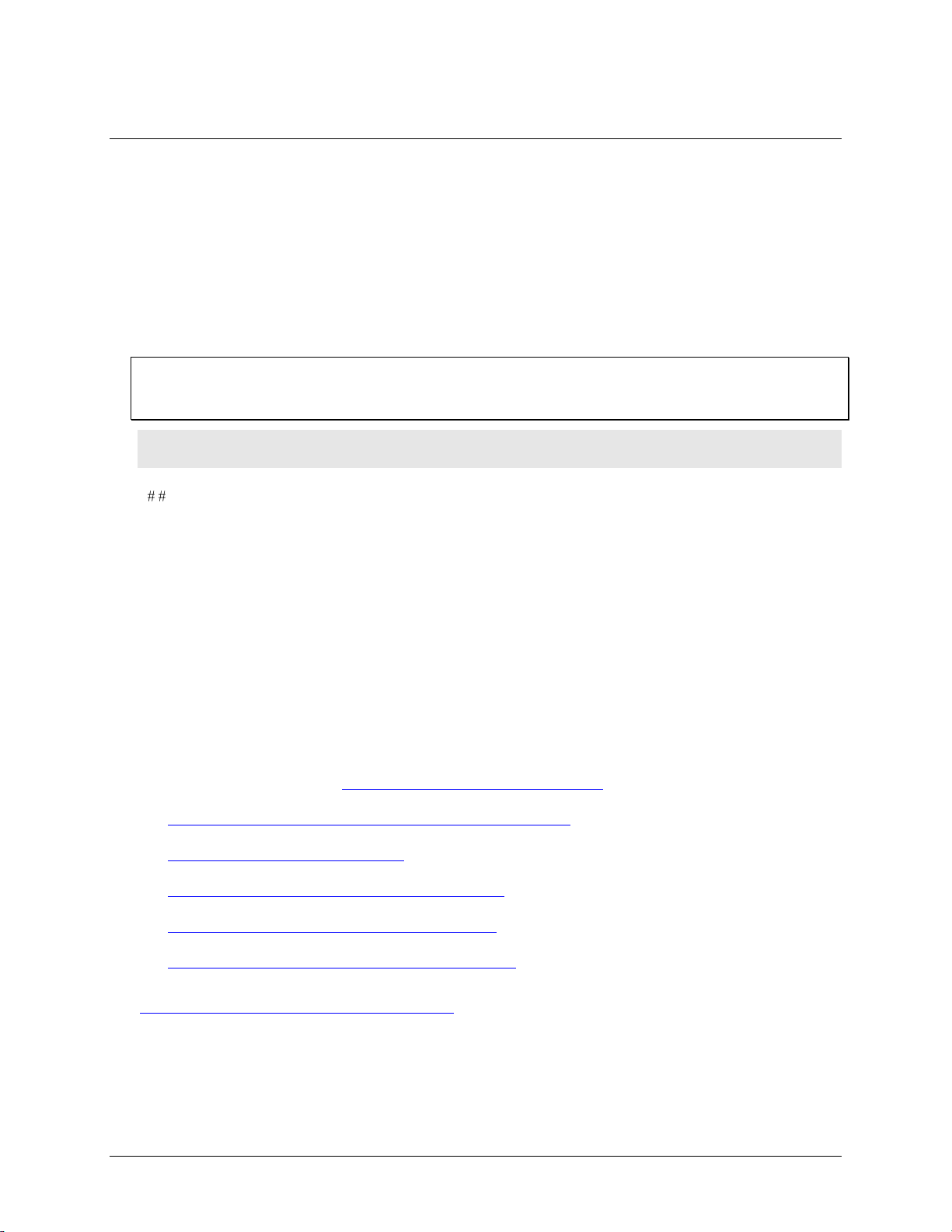
High-voltage applications
For high voltage applications, we recommend using the ACC-107 backshell with ten-position connector block
to ensure that the terminals are not accessible. The backshell also provides strain relief to protect the screw
terminals.
Figure 4. ACC-107 backshell with ten-position connector block
Additional details on this product are available on our web site at
www.mccdaq.com/cbicatalog/cbiproduct.asp?dept_id=586&pf_id=1871.
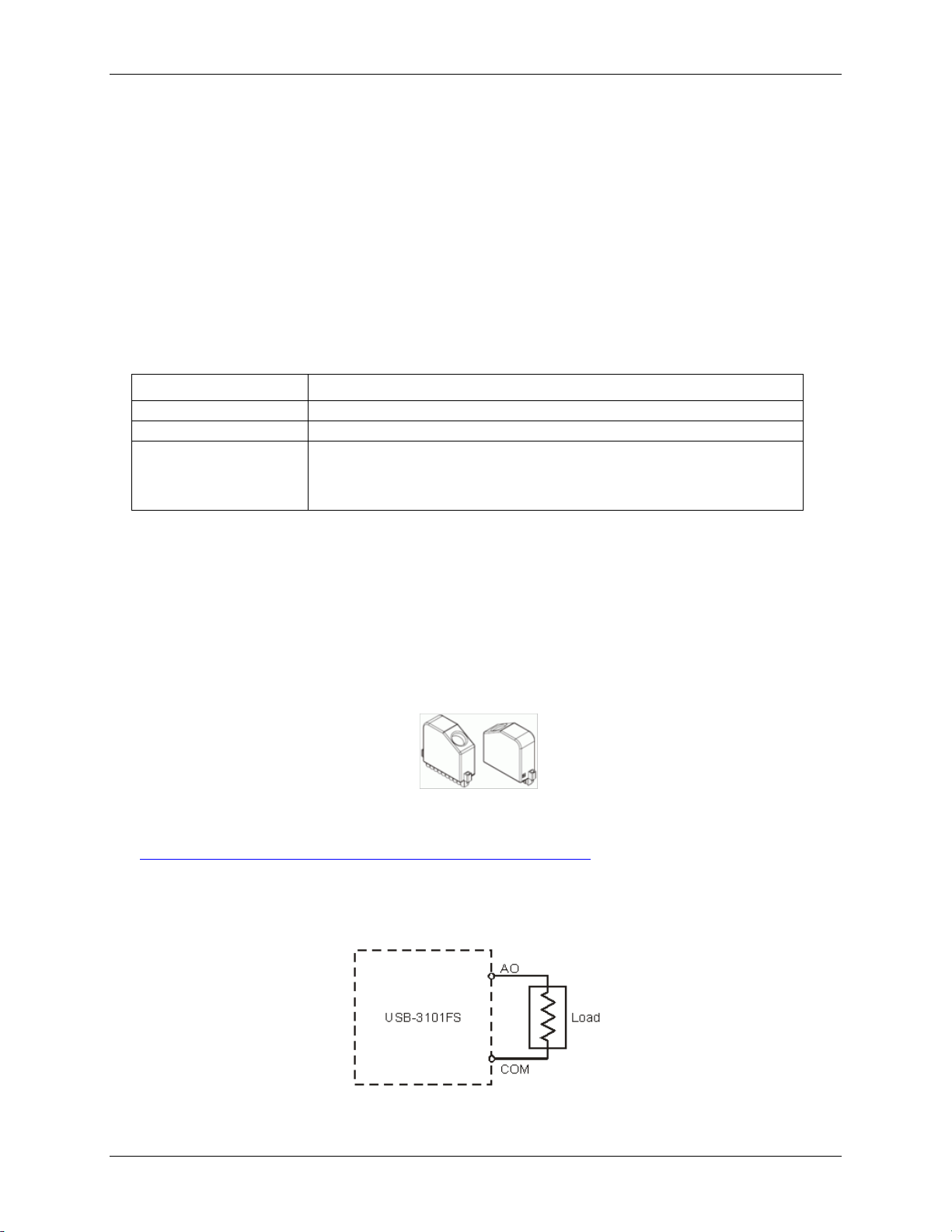
Connecting a load
Connect the positive lead of the load to the AO terminal, and the ground of the load to the COM terminal.
Figure 5. Connecting a load to the device
12
Page 13

USB-3101FS User's Guide Functional Details
Analog output circuitry
The USB-3101FS channels share a common ground that is isolated from the system. Each channel has a digitalto-analog converter (DAC) that produces a voltage signal.
Each channel also has ±30 V overvoltage and indefinite short-circuit protection.
Figure 6. Analog output circuitry for one channel
13
Page 14

Parameter
Conditions
Specification
Number of channels
4
D/A converter resolution
16-bit
D/A converter type
String
Output range
±10 V
Operating voltage
±10.7 V, nominal
±10.3 V, minimum
±11 V, maximum
Current drive
±1 mA per channel, maximum
Output impedance
0.1 Ω
Stability
Offset drift
±80 µV/ºC
Gain drift
6 ppm/ ºC
Protection
Overvoltage
±30 V
Short-circuit
Indefinitely
Update time
One channel
3 µs
Two channels
5 µs
Three channels
7.5 µs
Four channels
9.5 µs
Update rate
100 kS/s per channel, maximum
Noise
260 µV
rms
Slew rate
4 V/µs
Crosstalk
76 dB
Settling time
100 pF load, to 1 LSB
FS step:
20 µs
3 V step:
10 µs
0.1 V step:
8 µs
Glitch energy
256 steps, worst case
2 mV for 2 µs
Capacitive drive
1,500 pF, minimum
Monotonicity
16-bits
Differential non-linearity
–1 to 2 LSBs, maximum
Integral non-linearity (endpoint)
16 LSBs, maximum
Specifications
All specifications are subject to change without notice.
Typical for the range –40 to 70 °C unless otherwise noted.
All voltages are relative to COM unless otherwise noted.
Analog output
Table 1. Analog output specifications
Chapter 4
14
Page 15

USB-3101FS User's Guide Specifications
Measurement conditions
Percent of reading
Percent of range (Note 1)
Calibrated, maximum (–40 to 70 ºC)
0.35%
0.75%
Calibrated, typical (25 ºC, ±5 ºC)
0.01%
0.1%
Uncalibrated, maximum (–40 to 70 ºC)
2.2%
1.7%
Uncalibrated, typical (25 ºC, ±5 ºC)
0.3%
0.25%
Parameter
Specification
Power on voltage
0 V
Power consumption
625 mW, maximum
Thermal dissipation at 70 ºC
625 mW, maximum
Parameter
Specification
USB specification
USB 2.0 Hi-Speed mode (480 Mbps) is recommended.
Otherwise, USB 1.1 Full-Speed mode (12 Mbps).
Parameter
Specification
Operating temperature range
–40 to 70 °C
Storage temperature range
–40 to 85 °C
Ingress protection
IP 40
Operating humidity
10 to 90% relative humidity, non-condensing
Storage humidity
5 to 95% relative humidity, non-condensing
Maximum altitude
2000 meters (6561.679 feet)
Pollution degree (IEC60664)
2
Accuracy
Table 2. Analog input accuracy
Note 1: The range is equal to ±10.7 V.
Power
Table 3. Power specifications
Bus interface
Environmental
Table 4. General specifications
Table 5. Environmental specifications
15
Page 16

USB-3101FS User's Guide Specifications
Parameter
Conditions
Specification
Channel-to-COM
±11 V maximum
Isolation
Channel-to-channel
No isolation between channels
Channel-to-earth ground
Continuous
250 V
rms
, Measurement Category II (Note 2)
Withstand
2,300 V
rms
, verified by a 5 second dielectric withstand test
Parameter
Specification
Dimensions
4.5" L x 5.5" W x 1.5" H
Weight
1.2 lbs. (544 grams)
Connector type
Screw terminal
Screw terminal wiring
12 to 24 AWG copper conductor wire with 10 mm (0.39 in.) of insulation stripped
from the end.
Torque for screw terminals
0.5 to 0.6 N · m (4.4 to 5.3 lb. · in.)
Terminal
Signal
0
AO 0
1
Common (COM)
2
AO 1
3
Common (COM)
4
AO 2
5
Common (COM)
6
AO 3
7
Common (COM)
8
NC (No connection)
9
Common (COM)
ACC-121
10-position detachable screw terminal connector blocks (quantity 10)
ACC-107
Backshell with 10-position connector block (quantity 1)
Safety voltages
Table 6. Safety voltage specifications
Note 2: Measurement Category II is for measurements performed on circuits directly connected to the
electrical distribution system. This category refers to local-level electrical distribution, such as
that provided by a standard wall outlet, for example 115 V for U.S. or 230 V for Europe.
Caution! Do not connect the device to signals or use for measurements within Measurement Categories
III or IV.
Mechanical
Table 7. Mechanical specifications
Screw terminal connector
Table 8. Screw terminal connector specifications
Accessory products
Table 9. Screw terminal connector specifications
Connector pin out
16
Page 17

Declaration of Conformity
Manufacturer: Measurement Computing Corporation
Address: 10 Commerce Way
Suite 1008
Norton, MA 02766
USA
Measurement Computing Corporation declares under sole responsibility that the product
USB-3101FS
to which this declaration relates is in conformity with the relevant provisions of the following standards or other
documents:
Category: Electrical equipment for measurement, control and laboratory use.
EC EMC Directive 2004/108/EC: General Requirements, EN 61326-1:2006 (IEC 61326-1:2005).
Emissions: IEC 61326-2-1:2005.
EN 55011 (1990)/CISPR 11 Radiated emissions: Group 1, Class A
EN 55011 (1990)/CISPR 11 Conducted emissions: Group 1, Class A
Immunity: EN 61326-1:2006, Table 3.
IEC 61000-4-2 (1995): Electrostatic Discharge immunity, Criteria B.
IEC 61000-4-3 (1995): Radiated Electromagnetic Field immunity, Criteria A.
To maintain compliance to the standards of this declaration, the following conditions must be met.
The host computer, peripheral equipment, power sources, and expansion hardware must be CE
compliant.
All I/O cables must be shielded, with the shields connected to ground.
I/O cables must be less than 3 meters (9.75 feet) in length.
The host computer must be properly grounded.
Equipment must be operated in a controlled electromagnetic environment as defined by Standards EN
61326:2006, or IEC 61326:2005.
Declaration of Conformity based on tests conducted by Chomerics Test Services, Woburn, MA 01801, USA in
September, 2008. Test records are outlined in Chomerics Test Report #EMI5135.08.
We hereby declare that the equipment specified conforms to the above Directives and Standards.
Carl Haapaoja, Director of Quality Assurance
Page 18

Measurement Computing Corporation
10 Commerce Way
Suite 1008
Norton, Massachusetts 02766
(508) 946-5100
Fax: (508) 946-9500
E-mail: info@mccdaq.com
www.mccdaq.com
 Loading...