

Page 1

USB-2408 Series
USB-2408
USB-2408-2AO
Document Revision 3
June 2014
© Copyright 2014
User's Guide
24-Bit Multifunction Temperature and Voltage Devices
Page 2

HM USB-2408-Series.docx
Your new Measurement Computing product comes with a fantastic extra –
Management committed to your satisfaction!
Refer to www.mccdaq.com/execteam.html for the names, titles, and contact information of each key executive at Measurement
Computing.
Thank you for choosing a Measurement Computing product – and congratulations! You own the finest, and you can now enjoy
the protection of the most comprehensive warranties and unmatched phone tech support. It’s the embodiment of our mission:
To provide data acquisition hardware and software that will save time and save money.
Simple installations minimize the time between setting up your system and actually making measurements. We offer quick and
simple access to outstanding live FREE technical support to help integrate MCC products into a DAQ system.
Limited Lifetime Warranty: Most MCC products are covered by a limited lifetime warranty against defects in materials or
workmanship for the life of the product, to the original purchaser, unless otherwise noted. Any products found to be defective in
material or workmanship will be repaired, replaced with same or similar device, or refunded at MCC’s discretion. For specific
information, please refer to the terms and conditions of sale.
Harsh Environment Warranty® Program: Any Measurement Computing product that is damaged due to misuse, or any
reason, may be eligible for replacement with the same or similar device for 50% of the current list price. I/O boards face some
harsh environments, some harsher than the boards are designed to withstand. Contact MCC to determine your product’s
eligibility for this program
30 Day Money-Back Guarantee: Any Measurement Computing Corporation product may be returned within 30 days of
purchase for a full refund of the price paid for the product being returned. If you are not satisfied, or chose the wrong product by
mistake, you do not have to keep it.
These warranties are in lieu of all other warranties, expressed or implied, including any implied warranty of merchantability or
fitness for a particular application. The remedies provided herein are the buyer’s sole and exclusive remedies. Neither
Measurement Computing Corporation, nor its employees shall be liable for any direct or indirect, special, incidental or
consequential damage arising from the use of its products, even if Measurement Computing Corporation has been notified in
advance of the possibility of such damages.
Trademark and Copyright Information
Measurement Computing Corporation, InstaCal, Universal Library, and the Measurement Computing logo are either trademarks
or registered trademarks of Measurement Computing Corporation. Refer to the Copyrights & Trademarks section on
mccdaq.com/legal for more information about Measurement Computing trademarks. Other product and company names
mentioned herein are trademarks or trade names of their respective companies.
© 2011-2014 Measurement Computing Corporation. All rights reserved. No part of this publication may be reproduced, stored in
a retrieval system, or transmitted, in any form by any means, electronic, mechanical, by photocopying, recording, or otherwise
without the prior written permission of Measurement Computing Corporation.
Notice
Measurement Computing Corporation does not authorize any Measurement Computing Corporation product for use
in life support systems and/or devices without prior written consent from Measurement Computing Corporation.
Life support devices/systems are devices or systems that, a) are intended for surgical implantation into the body, or
b) support or sustain life and whose failure to perform can be reasonably expected to result in injury. Measurement
Computing Corporation products are not designed with the components required, and are not subject to the testing
required to ensure a level of reliability suitable for the treatment and diagnosis of people.
2
Page 3

Table of Contents
Preface
About this User's Guide ....................................................................................................................... 5
What you will learn from this user's guide ......................................................................................................... 5
Conventions in this user's guide ......................................................................................................................... 5
Where to find more information ......................................................................................................................... 5
Chapter 1
Introducing the USB-2408 Series ........................................................................................................ 6
Overview: USB-2408 Series features ................................................................................................................. 6
USB-2408 Series block diagram ........................................................................................................................ 7
Chapter 2
Installing a USB-2408 Series Device ................................................................................................... 8
What comes with your shipment? ....................................................................................................................... 8
Hardware .......................................................................................................................................................................... 8
Documentation ................................ ................................................................ ................................................................ .. 8
Unpacking........................................................................................................................................................... 8
Installing the software ........................................................................................................................................ 8
Installing the hardware ....................................................................................................................................... 8
Calibrating .......................................................................................................................................................... 9
Factory calibration ............................................................................................................................................................ 9
Field calibration ................................................................................................................................................................ 9
Chapter 3
Functional Details ............................................................................................................................... 10
External components ........................................................................................................................................ 10
USB connector .................................................................................................................................................................10
LEDs ................................................................................................................................................................................10
Screw terminals................................................................................................................................................................10
Signal connections ............................................................................................................................................ 12
Input isolation ..................................................................................................................................................................12
Analog/TC input ..............................................................................................................................................................12
Analog input mode ...........................................................................................................................................................13
Gain queue .......................................................................................................................................................................13
TC input mode .................................................................................................................................................................14
Analog output (USB-2408-2AO only) .............................................................................................................................16
Digital I/O ........................................................................................................................................................................16
Internal pull-up/pull-down capability...............................................................................................................................17
External pull-up/pull-down capability .............................................................................................................................19
Counter input ...................................................................................................................................................................19
Ground ................................................................................................................................................................ .............19
Mechanical drawings ................................................................................................................................ ........ 20
Chapter 4
Specifications ...................................................................................................................................... 21
Analog input ..................................................................................................................................................... 21
Channel configurations ..................................................................................................................................... 22
Compatible sensors ..........................................................................................................................................................22
Accuracy ........................................................................................................................................................... 22
Thermocouple measurement accuracy ............................................................................................................................. 22
Analog input DC voltage measurement accuracy ............................................................................................................23
Input bandwidth ...............................................................................................................................................................24
Noise performance ...........................................................................................................................................................24
Channel switching error ...................................................................................................................................................25
Throughput rate ................................................................................................................................................ 25
3
Page 4

USB-2408 Series User's Guide
Analog voltage output (USB-2408-2AO only) ................................................................................................. 26
Analog input/output calibration ........................................................................................................................ 27
Digital input/output........................................................................................................................................... 28
Counter ............................................................................................................................................................. 29
Memory ............................................................................................................................................................ 29
Microcontroller ................................................................................................................................................. 29
Power ................................................................................................................................................................ 30
USB specifications ........................................................................................................................................... 30
Environmental .................................................................................................................................................. 30
Mechanical ....................................................................................................................................................... 30
Screw terminal connector type and pinout ....................................................................................................... 30
Screw terminal pinout ......................................................................................................................................................31
Declaration of Conformity .................................................................................................................. 33
4
Page 5

About this User's Guide
What you will learn from this user's guide
This user's guide describes the Measurement Computing USB-2408 Series data acquisition devices and lists
device specifications.
Conventions in this user's guide
For more information about …
Text presented in a box signifies additional information and helpful hints related to the subject matter you are
reading.
Caution! Shaded caution statements present information to help you avoid injuring yourself and others,
damaging your hardware, or losing your data.
bold text Bold text is used for the names of objects on a screen, such as buttons, text boxes, and check boxes.
italic text Italic text is used for the names of manuals and help topic titles, and to emphasize a word or phrase.
Preface
Where to find more information
Additional information about USB-2408 Series hardware is available on our website at www.mccdaq.com. You
can also contact Measurement Computing Corporation by phone, fax, or email with specific questions.
Phone: 508-946-5100 and follow the instructions for reaching Tech Support
Fax: 508-946-9500 to the attention of Tech Support
Email: techsupport@mccdaq.com
5
Page 6

Chapter 1
Introducing the USB-2408 Series
Overview: USB-2408 Series features
The USB-2408, USB-2408-2AO includes the following devices:
USB-2408
USB-2408-2AO
These devices are USB 2.0 full-speed devices that are supported under the following operating systems:
Microsoft Windows® 8/7/Vista®/XP (32-bit or 64-bit)
Macintosh (32-bit or 64-bit)
Linux (32-bit or 64-bit)
Each USB-2408 Series device provides the following features:
16 single-ended (SE) or eight differential (DIFF) 24-bit analog inputs with sampling rates up to 1 kS/s.
Each channel is software-configurable as SE or DIFF. For each DIFF channel pair, you lose one SE
channel.
Analog input ranges of ±10 V, ±5 V, ±2.5 V, ±1.25 V, ±0.625 V, ±0.312 V, ±0.156 V, and ±0.078 V.
Up to eight analog inputs can be configured as DIFF thermocouple (TC) inputs, which include built-in
cold-junction compensation and open TC detection.
Computer protection provided through a minimum of 500 VDC input isolation between field wiring and the
USB interface.
Eight lines of digital I/O and two 32-bit counters.
Screw terminals for field wiring connections
The USB-2408-2AO also provides two 16-bit analog output channels. You can pace a single channel at rates of
up to 1 kS/s. You can pace both channels simultaneously at rates of up to 500 S/s.
6
Page 7
USB-2408 Series User's Guide Introducing the USB-2408 Series
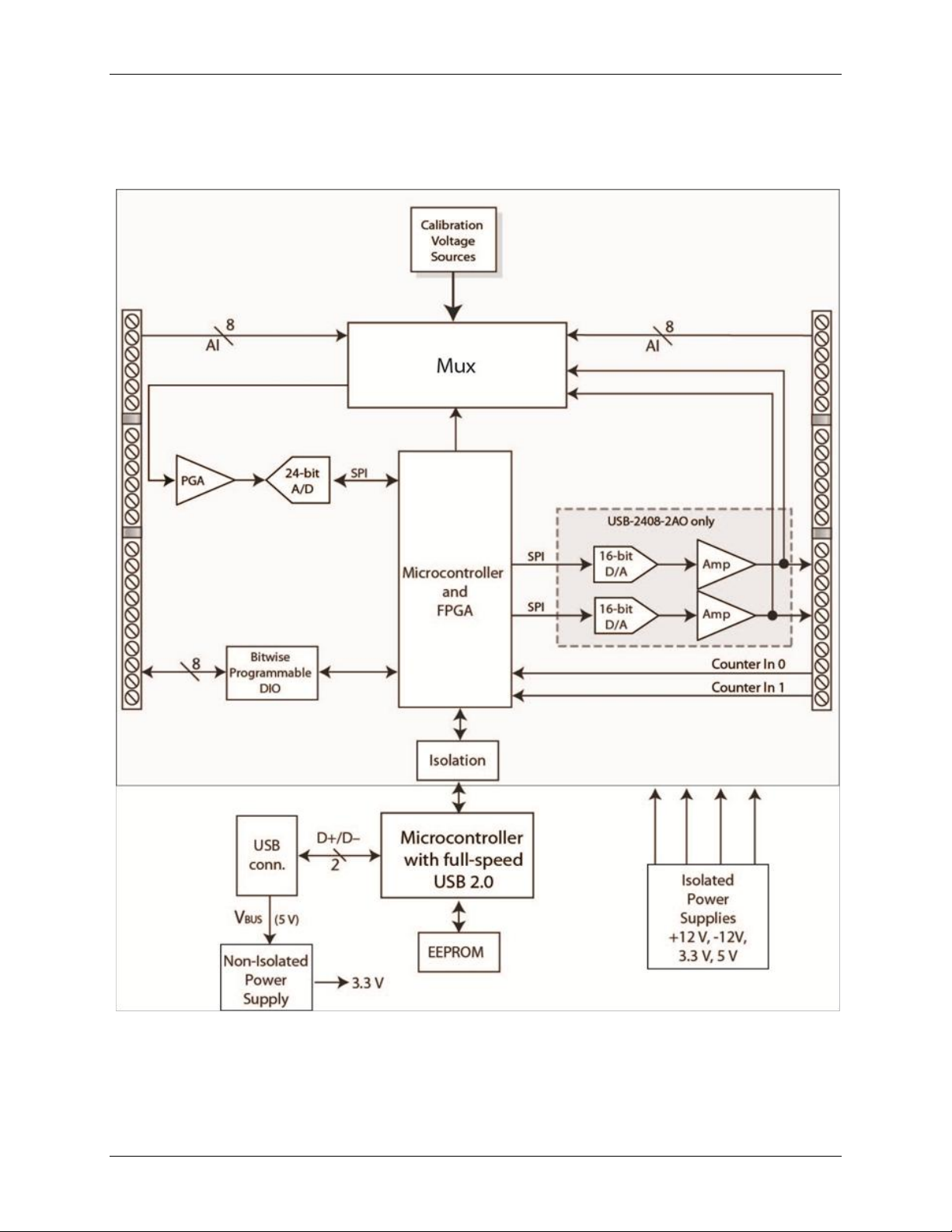
USB-2408 Series block diagram
USB-2408 Series functions are illustrated in the block diagram shown here.
Figure 1. USB-2408 Series functional block diagram
7
Page 8

Chapter 2
Installing a USB-2408 Series Device
What comes with your shipment?
As you unpack your USB-2408 Series device, verify that the following components are included.
Hardware
USB-2408 Series device (USB-2408 or USB-2408-2AO)
USB cable (2-meter length)
Documentation
MCC DAQ Quick Start Guide
The Quick Start Guide booklet provides an overview of the MCC DAQ software you received with the device,
and includes information about installing the software. Please read this booklet completely before installing any
software or hardware.
Unpacking
As with any electronic device, take care while handling to avoid damage from static electricity. Before
removing the USB-2408 Series device from its packaging, ground yourself using a wrist strap or by simply
touching the computer chassis or other grounded object to eliminate any stored static charge.
If the device is damaged, notify Measurement Computing Corporation immediately by phone, fax, or e-mail.
Knowledgebase: kb.mccdaq.com
Phone: 508-946-5100 and follow the instructions for reaching Tech Support
Fax: 508-946-9500 to the attention of Tech Support
Email: techsupport@mccdaq.com
For international customers, contact your local distributor. Refer to the International Distributors section on our
website at www.mccdaq.com/International.
Installing the software
Refer to the Quick Start Guide for instructions on installing the software on the MCC DAQ CD. This booklet is
available in PDF at www.mccdaq.com/PDFmanuals/DAQ-Software-Quick-Start.pdf.
Installing the hardware
Install the software before you install your device
A driver needed to run the USB-2408 Series device is installed when you install the software. Therefore, you
need to install the software package you plan to use before you install the hardware.
To connect a USB-2408 Series device to your system, turn on your computer and connect the USB cable to an
available USB port on the computer or to an external USB hub connected to the computer. Connect the other
end of the USB cable to the USB connector on the device. No external power is required.
When you connect the device for the first time to a computer running Windows, a Found New Hardware dialog
opens when the operating system detects the device. The dialog closes after the device is installed.
A green Status LED indicates the device status. When the LED is on, the device is powered and ready for
operation. If the LED is not on, the device is not powered or did not initialize.
Figure 2 on page 10 shows the location of the STATUS LED.
8
Page 9

USB-2408 Series User's Guide Installing a USB-2408 Series Device
Caution! Do not disconnect any device from the USB bus while the computer is communicating with the
USB-2408 Series device, or you may lose data and/or your ability to communicate with the
device.
If the Status LED turns off
If the Status LED turns on but then turns off, the computer has lost communication with the USB-2408 Series
device. To restore communication, disconnect the USB cable from the computer and then reconnect it. This
should restore communication, and the Status LED should turn on.
Calibrating
Factory calibration
The Measurement Computing Manufacturing Test department performs the initial factory calibration. Contact
Measurement Computing for details about how to return your device and have it calibrated to the factory
specifications.
Field calibration
USB-2408 Series hardware supports field calibration. You should calibrate the device with InstaCal whenever
the ambient temperature changes by more than ±10 °C from the last calibration.
9
Page 10
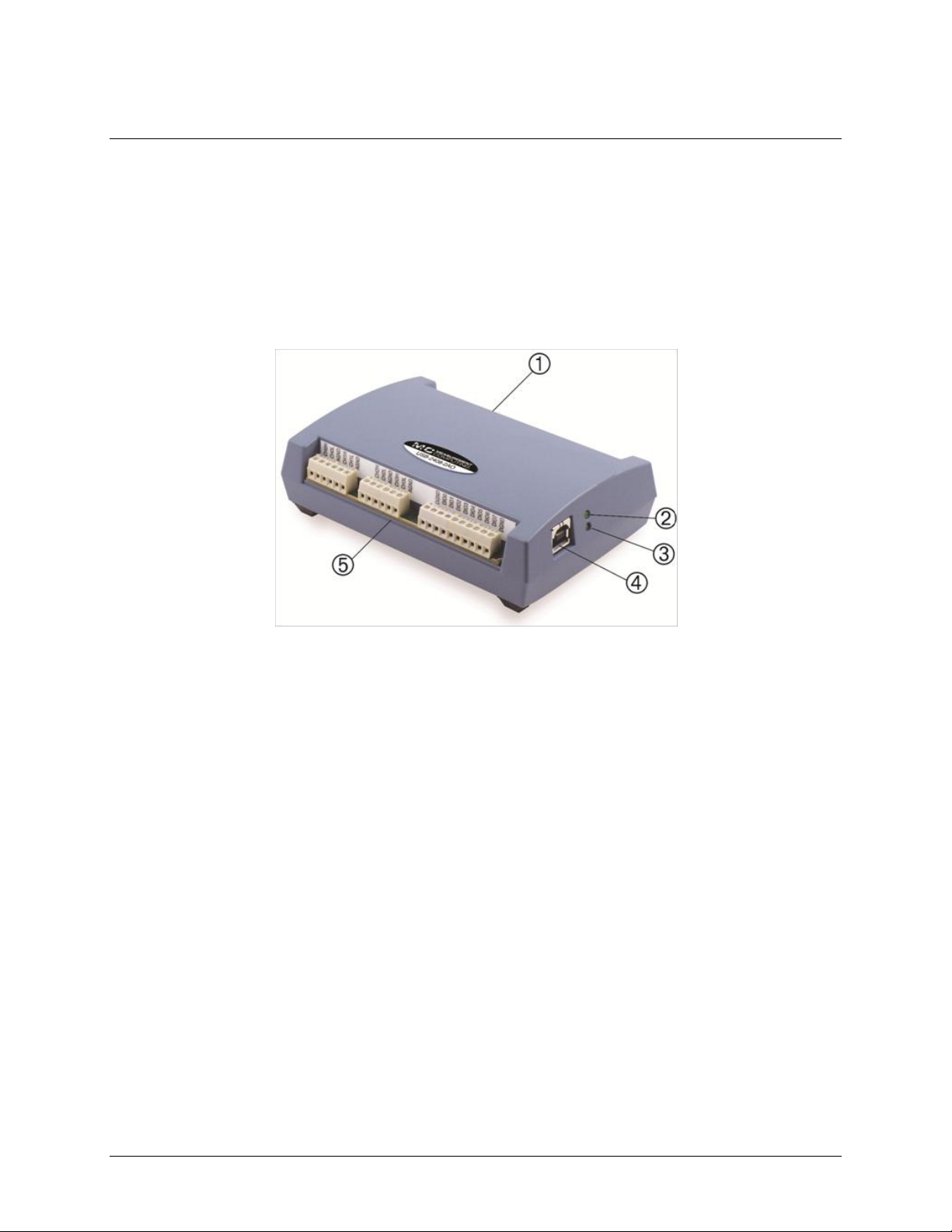
1
Screw terminal pins 23 to 44
4
USB Connector
2
Status LED
5
Screw terminal pins 1 to 22
3
Activity LED
Functional Details
External components
USB-2408 Series devices have the following external components:
USB connector
LEDs
Screw terminals
Figure 2 shows the location of each component.
Chapter 3
Figure 2. USB-2408 Series components
USB connector
The USB connector provides 5 V power and communication. No external power supply is required.
LEDs
USB-2408 Series devices have two LEDs – STATUS and ACTIVITY.
The Status LED is lit when the device is detected and installed on the computer.
The Activity LED indicates the communication status of a device. This LED blinks when data is
transferred, and is off when the device is not communicating.
Screw terminals
USB-2408 Series devices have two banks of screw terminals. Screw terminal functions for DIFF and SE modes
are identified in Figure 4 and Figure 3.
The USB-2408 Series device screw terminals provide the following connections:
16 SE (CH0 to CH15 – see Figure 3) or eight DIFF (CH0H/CH0L to CH7H/CH7L) analog input connections
Eight digital I/O connections (DI00 to DI07)
Two analog output connections (AOUT0, AOUT1) – USB-2408-2AO only
Two counter inputs (CTR0, CTR1)
One power output (+5V)
10 analog grounds (AGND), four digital grounds (DGND), and one chassis ground (CHAS)
10
Page 11
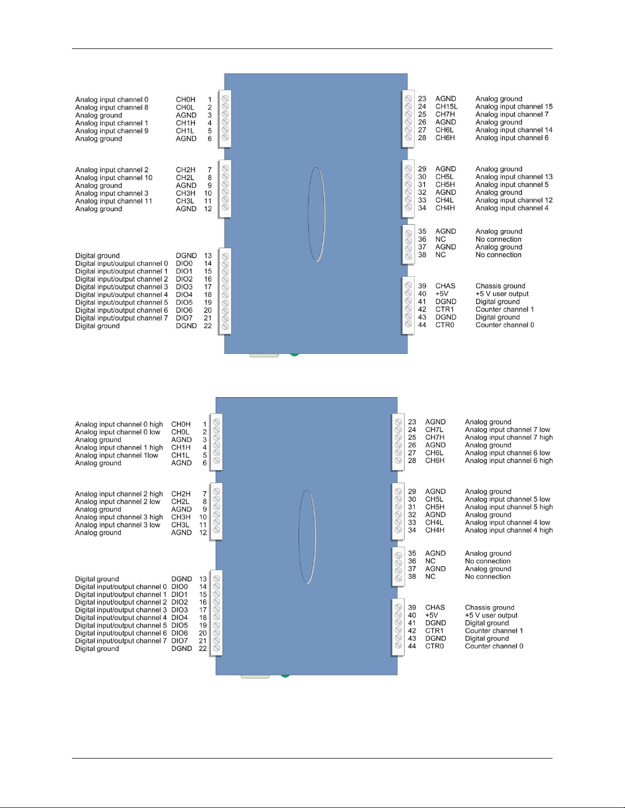
USB-2408 Series User's Guide Functional Details
Figure 3. SE mode pinout
* These pins are labeled NC (no connection) on the USB-2408.
Figure 4. DIFF mode pinout
* These pins are labeled NC (no connection) on the USB-2408.
11
Page 12

USB-2408 Series User's Guide Functional Details
Signal connections
Input isolation
USB-2408 Series devices are isolated data acquisition devices. The analog I/O, digital I/O, counters, and all the
digital control/timing are referenced to an isolated ground as shown in the figure below. This ground is
physically and electrically separate from the ground used by the circuit connected to the system bus interface.
Isolation provides a barrier between the host computer and potentially hazardous voltages by physically and
electrically separating two parts of the measurement device.
The non-isolated ground is common to the chassis ground of the computer, while the isolated ground is not.
All analog measurements are made relative to the isolated ground. See Figure 5 for details.
Figure 5. USB-2408 Series input isolation diagram
When making measurements in industrial environments, DAQ devices can encounter hazardous voltages,
transients, large common mode voltages and fluctuating ground potentials. Any one of these issues can
seriously degrade the measurement accuracy of the device and possibly damage the measurement instrument.
To overcome these issues, some DAQ devices provide physical and electrical isolation. Some of the benefits of
isolation include:
Safety: A DAQ device employing physical and electrical isolation helps to keep high voltages and
transients from damaging the system-side host computer.
Ground loops: Improper grounding of the signal source that the DAQ device is measuring is one of the
most common sources of noise and measurement inaccuracies. Isolation improves the measurement
accuracy by physically preventing ground loops. Ground loops – a common source of noise and error – are
the results of a measurement system having multiple grounds at different potentials.
Common mode rejection: With isolation, a DAQ device can measure small signals in the presence of large
common mode voltages. Isolation increases the ability of the measurement system to reject common mode
voltages. The common mode voltage is the signal that is common to both the positive and negative inputs
of the measurement device, but is not part of the signal to measure.
Analog/TC input
Each analog input channel has the following measurement parameters:
Voltage input range
TC type J, K, T, E, R, S, B, or N
You can select a unique input range or signal type for each channel. For example, one channel could be used for
volts and another for temperature.
12
Page 13

USB-2408 Series User's Guide Functional Details
Analog input mode
You can configure the analog inputs for SE or DIFF mode. The input voltage range is software selectable for
±10 V, ±5 V, ±2.5 V, ±1.25 V, ±0.625 V, ±0.312 V, ±0.156 V, or ±0.078 V.
With SE mode, connect up to 16 inputs to screw terminals CH0 to CH15. SE mode requires two wires:
Connect one wire to the signal you want to measure (CHx).
Connect one wire to the analog ground reference (AGND).
Refer to Figure 3 on page 11 for the location of the SE inputs.
With DIFF mode, connect up to eight differential inputs to screw terminals CH0H/CH0L to CH7H/CH7L.
DIFF mode requires two wires plus a ground reference:
Connect one wire to the high/positive signal (CHxH).
Connect one wire to the low/negative signal (CHxL).
Connect one wire to the analog ground reference (AGND).
Refer to Figure 4 on page 11 for the location of the DIFF inputs.
When connecting DIFF voltage inputs to a "floating" voltage source, make sure there is a DC return path from
each voltage input to ground. You make this path by connecting a resistor from each low channel input to an
AGND pin. A value of approximately 100 kΩ can be used for most applications. This does not apply to
channels configured for TC input, as they have their own internal reference.
Leave unused input channels either floating or tied to an AGND terminal.
Source impedances should be kept as small as possible to avoid settling time and accuracy errors.
Figure 6 shows a DIFF voltage connection using a ground path resistor.
Figure 6. DIFF voltage connection with ground path resistor example
Gain queue
Use the USB-2408 Series channel - gain queue feature to configure a list of channels, modes, and gains for each
scan. The settings are stored in a channel – gain queue list that is written to local memory on the device.
The channel - gain queue list contains one or more channel numbers and range settings. You can configure up to
64 elements. The channels can be listed in any order, and can include duplicate channels for sampling at
different ranges.
13
Page 14

USB-2408 Series User's Guide Functional Details
Element
Channel
Range
0
CH0
BIP10V
1
CH1
BIP5V
2
CH0
BIP2Pt5VOLTS
3
CH4
BIP2Pt5VOLTS
4
CH8
BIP2Pt5VOLTS
5
CH0
BIP5V
6
CH1
BIP1Pt25VOLTS
7
CH7
BIP5V
8
CH0
BIP1Pt25VOLTS
9
CH15
BIP10V
10
CH9
BIP1Pt25VOLTS
11
CH10
BIP2Pt5VOLTS
An example of a 12-element list is shown in the table below.
Sample channel gain queue list
Carefully match the gain to the expected voltage range on the associated channel or an over range condition
may occur. Although this condition does not damage the device, it does produce a useless full-scale reading,
and can introduce a long recovery time due to saturation of the input channel.
For more information about analog signal connections
For more information about analog input connections, refer to the Guide to Signal Connections (this document
is available on our web site at www.mccdaq.com/signals/signals.pdf).
TC input mode
You can make up to eight high-resolution DIFF TC measurements with a USB-2408 Series device. Built-in
cold-junction compensation sensors are provided for each of the screw-terminal blocks and any supported TC
type can be attached to any of the 8 TC channels.
Do not connect TCs as SE – doing so can cause false readings.
You do not need to use ground-referencing resistors for TC inputs because the analog front-end circuit level-
shifts the TC output into the common-mode input range of the A/D.
USB-2408 Series devices also provide an open TC detection feature for each of the analog input channels
configured for TC measurement. This feature is enabled or disabled by software, and when enabled, it detects if
an open-circuit condition exists at the TC sensor.
USB-2408 Series devices provide electrostatic discharge (ESD) protection for each of the TC inputs. However,
before handling TC sensors, follow standard ESD practices and discharge any accumulated ESD charge.
Once the TC sensor is connected to the device, the configuration options have been selected, and the
recommended 45 minute warm up has elapsed, the device is ready to make high-resolution DIFF temperature
measurements.
Built-in cold junction compensation (CJC) automatically compensates for the additional thermal EMFs
generated by connecting the TC leads to the USB-2408 Series device terminal blocks.
CJC is performed using a high-resolution temperature sensor connected close to the device terminal blocks. The
device includes two separate CJC sensors – one on each side of the PCB. Software corrects for the additional
TCs created at the terminals.
Once the A/D and CJC data is collected, the application software uses this data to linearize to an accurate
temperature reading. The TC linearization uses the latest NIST linearization coefficients for each of the eight
TC types supported by USB-2408 Series devices.
When configuring TC sensors, keep any stray capacitance as small as possible relative to AGND to avoid
settling time and accuracy errors. For TC channels do not provide a return path to ground as this is done
internally.
14
Page 15

USB-2408 Series User's Guide Functional Details
Figure 7 shows a typical TC connection.
Figure 7. DIFF TC connection example
Noise filtering, data rate and throughput rate
Although the USB-2408 Series A/D converter has a maximum data rate of 3,750 samples per second, the actual
throughput rate you observe for voltage and temperature data is determined by these formulas.
Maximum single-channel throughput:
Maximum multiple-channel throughput:
where n is the number of channels
See Table 18 and Table 19 in the Specifications chapter for details.
This drop-off in throughput rate is due to the noise filtering feature in the device. You can control the amount of
the noise filtering by adjusting the data rate setting. By reducing the data rate, the averaging of samples
increases, and noise drops correspondingly.
Figure 8 illustrates this inverse relationship. This graph applies to the A/D converter only – do not expect this
level of performance from a USB-2408 Series device itself.
Figure 8. USB-2408 Series A/D converter data rate vs. noise graph
If low noise is your main concern, you can operate the USB-2408 Series device at very low data rates starting
from 2.5 samples per second (S/s). At low rates, much of the noise is averaged out of the data, and issues such
as reference noise become less important.
15
Page 16

USB-2408 Series User's Guide Functional Details
At higher data rates, higher-frequency noise sources are not averaged out and begin to be troublesome. These
noise sources include the noise inherent in the A/D converter itself, which is not reducible.
Since TCs can pick up noise in your environment, select a data rate based on the primary noise frequency. For
example, to reduce the effect of 60 Hz noise, select a data rate of 60 (or a supported submultiple of 60, such as
10 or 5).
Multiple-channel throughput rates
When setting different sample rates for channels, be aware that all the channels will be sampled within the same
sample window based on the channel with the lowest sample rate.
For example, if you set a 10 Hz data rate for channel 0, and a 50 Hz data rate for channel 1, basically, both
channels pass the same number of samples per second to the host computer. However, more averaging is
performed on channel 0 samples; therefore, channel 0 is sampled at a higher resolution.
The USB-2408 Series A/D converter performs averaging, and the number of averages equals 30,000/data rate.
In this example, channel 0 is sampled 3000 times over 100 ms, and all samples are averaged into one sample.
Then, channel 1 is sampled 600 times over 20 ms, and samples are likewise averaged into one sample.
The final samples are available to you at a maximum rate of about 8 Hz (8.245 Hz).
Figure 9. USB-2408 Series data rate vs. resolution example
Analog output (USB-2408-2AO only)
The USB-2408-2AO has two 16-bit analog outputs (AOUT0 and AOUT1). Both outputs can be updated
simultaneously at a rate of 500 S/s per channel. One output can be updated at a rate of 1000 S/s. The output
range is fixed at ±10 V. The outputs default to 0 V when the host computer is shut down or suspended, or when
a reset command is issued to the device.
Digital I/O
You can connect up to eight digital I/O lines to DIO0 through DIO7. The digital I/O terminals can detect the
state of any TTL-level input.
Digital input voltage ranges of up to 0 to +15 V are permitted, with thresholds of 0.6 V (low) and 2.2 V (high).
Each DIO channel is an open-drain, which, when used as an output, is capable of sinking up to 150 mA for
direct drive applications.
16
Page 17

USB-2408 Series User's Guide Functional Details
Figure 10 shows a typical DIO connection.
Figure 10. Digital output connection example
The figure represents connections for one channel. The other seven channels are connected in the same manner.
The maximum sink current is 150 mA per 8-channel bank, or if all eight channels are used, 18 mA (maximum)
per channel.
Internal pull-up/pull-down capability
Unconnected inputs are pulled high by default to 5 V using 47 kΩ resistors through jumper J6 on the circuit
board. The pull-up/pull-down voltage is common to all 47 kΩ resistors. Complete the following steps to
configure these inputs.
Caution! The discharge of static electricity can damage some electronic components. Before removing the
USB-2408 Series device from its housing, ground yourself using a wrist strap or touch the
computer chassis or other grounded object to eliminate any stored static charge.
To open the case and set the J6 jumper, do the following.
1. Turn the device over and rest the top of the housing on a flat, stable surface.
2. Peel off the four rubber feet on the bottom of the device to access the screws.
3. Remove the four screws from the bottom of the device.
4. Hold both the top and bottom sections together, turn the device over and rest it on the surface, then
carefully remove the top section of the case to expose the circuit board.
5. Configure jumper J6 for either pull-up (pins 1-2) or pull-down (pins 2-3). The jumper is configured by
default for pull-up. Figure 11 shows the location of the jumper on the board.
17
Page 18

USB-2408 Series User's Guide Functional Details
Figure 11. Location of J6 jumper
Figure 12 shows the jumper configured for pull-up and pull-down.
Figure 12. J6 jumper configurations
6. Replace the top section of the case, and fasten it to the bottom section with the four screws. Replace the
rubber feet.
For more information about digital signal connections
For general information about digital signal connections and digital I/O techniques, refer to the Guide to DAQ
Signal Connections (available on our web site at www.mccdaq.com/signals/signals.pdf).
The pull-up/pull-down voltage is common to all of the internal 47 kΩ resistors.
18
Page 19
USB-2408 Series User's Guide Functional Details
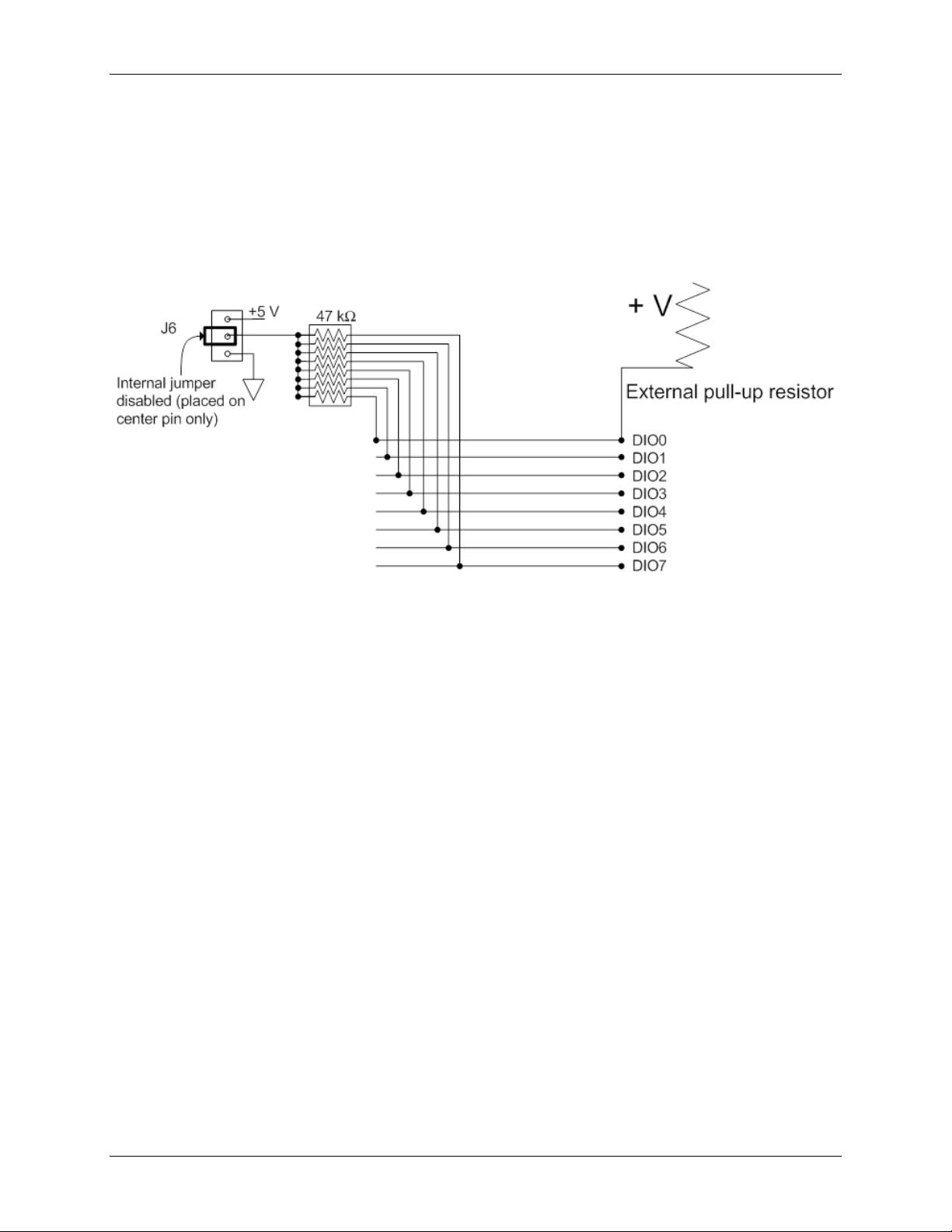
External pull-up/pull-down capability
You can also place an external pull-up resistor on any of the DIO bits, which enables you to pull the DIO bit up
to a voltage that exceeds the internal +5 V pull-up voltage.
When using external pull-up resistors, be aware of the following:
You should either remove the J6 jumper, or store it by attaching it to one of the three pins.
When using external pull-up resistors, be aware that the internal resistors cause a slight voltage impedance
shift to digital lines in the "on" state as various lines change between the on/off states.
Figure 13. Digital I/O external resistor configuration
Counter input
The CTR0 and CTR1 terminals are 32-bit event counters that can accept frequency inputs up to 1 MHz. The
internal counter increments when the TTL levels transition from low to high.
Ground
The analog ground (AGND) terminals provide a common ground for all analog channels.
The digital ground (GND) terminals provide a common ground for the digital and counter channels and the
power terminal.
19
Page 20
USB-2408 Series User's Guide Functional Details
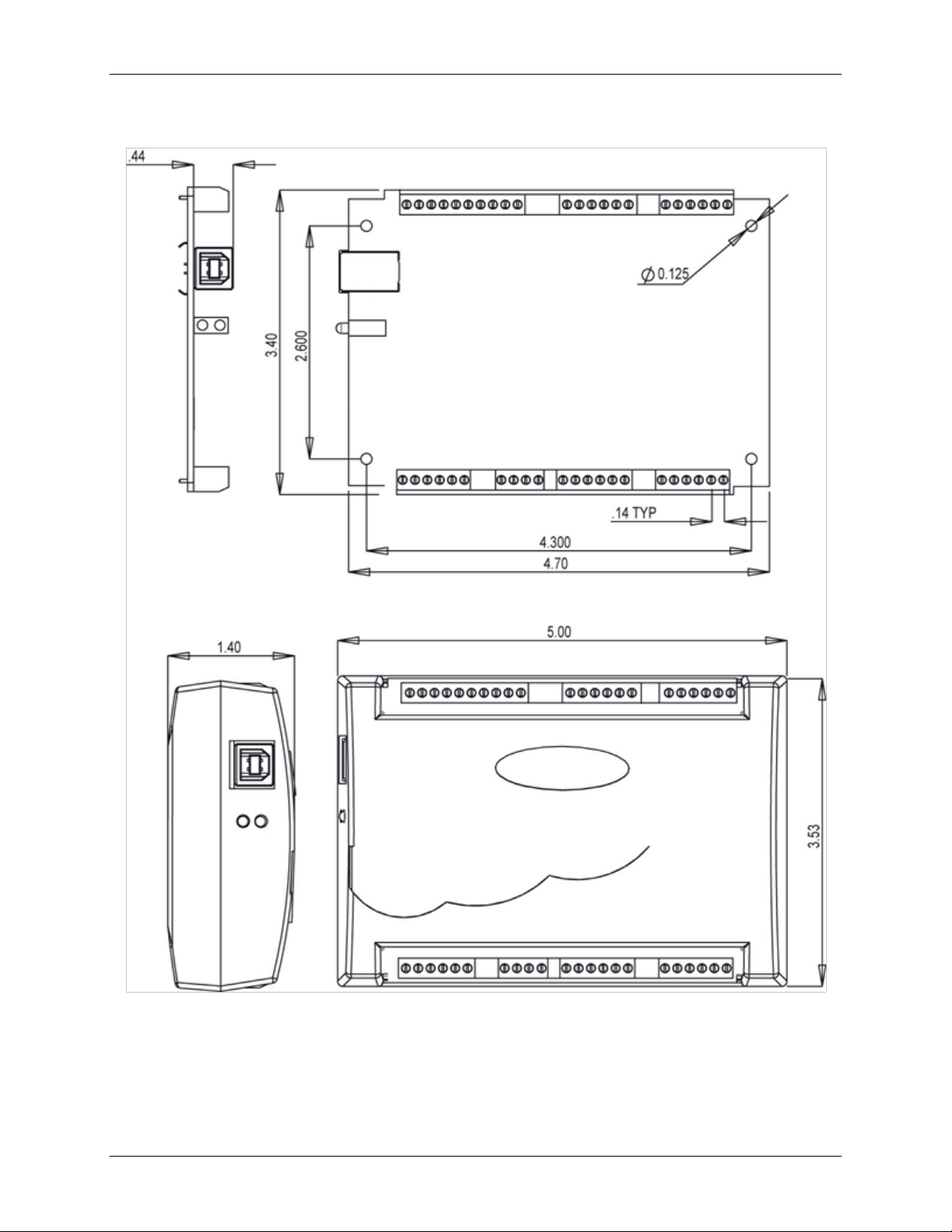
Mechanical drawings
Figure 14. USB-2408 Series device circuit board (top) and enclosure dimensions
20
Page 21

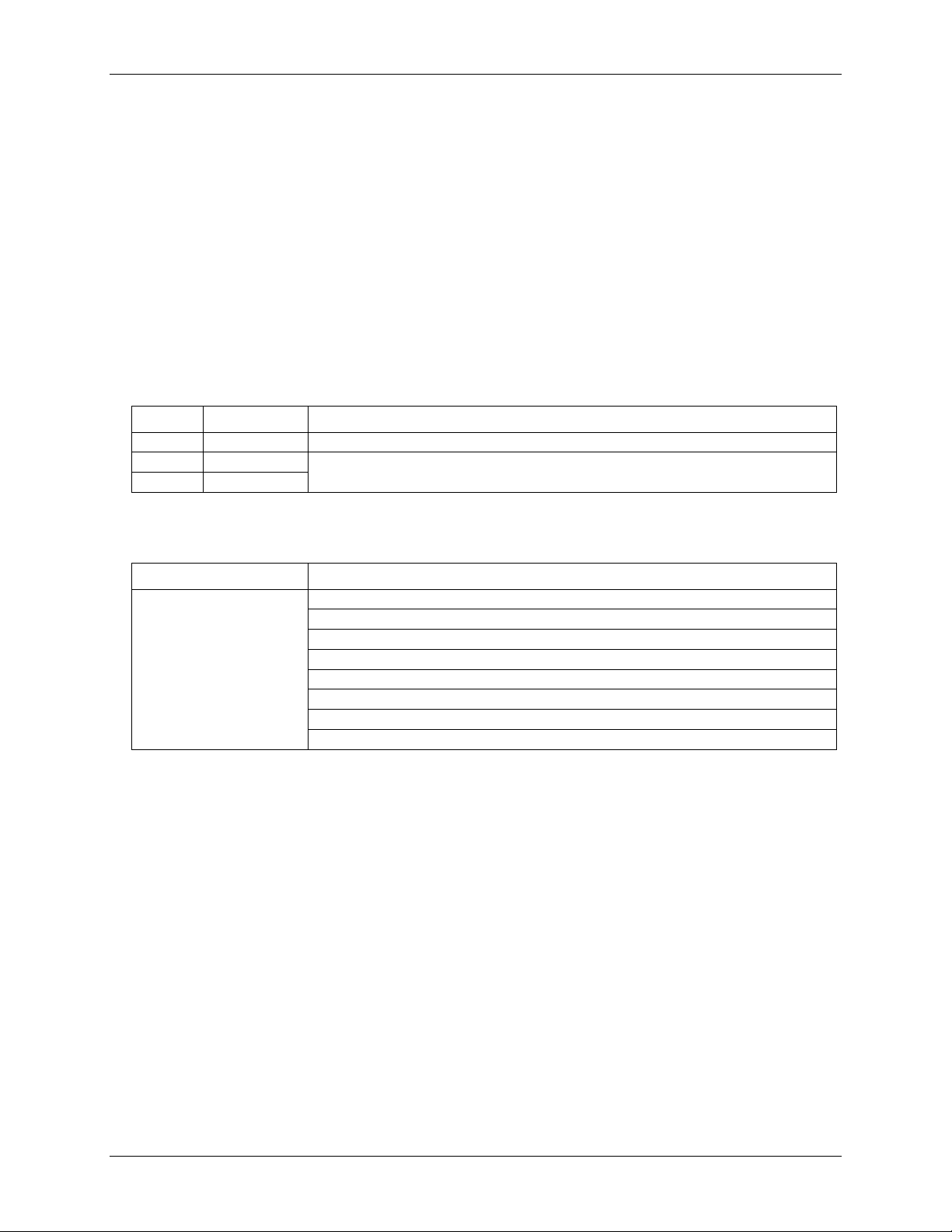
Parameter
Conditions
Specification
A/D converter type
ADS1256, 24-bit Sigma Delta
A/D data rates
3750 S/s, 2000 S/s, 1000 S/s, 500 S/s, 100 S/s, 60 S/s, 50 S/s,
25 S/s, 10 S/s, 5 S/s, 2.5 S/s
Throughput
Single channel: 2.5 S/s to 1102.94 S/s (software-selectable)
Multiple channels: 0.16 S/s to 551.47 S/s (software-selectable)
See Table 11 and Table 12 for details.
Number of channels
16 single-ended or 8 differential (software-selectable).
Thermocouples require differential mode. For each channel
configured as differential, you essentially lose two single-ended
channels.
Input isolation
500 VDC min between field wiring and USB interface
Channel configurations
Temperature sensor input, software-selectable to match sensor
type
Voltage input
Input voltage range
Thermocouple mode
±0.078125 V
Voltage mode (Note 1)
±10 V, ±5 V, ±2.5 V, ±1.25 V, ±0.625 V, ±0.3125 V,
±0.15625 V, ±0.078125 V (software-selectable)
Absolute maximum input
voltage
CxH-CxL relative to
GND
±22 V max (power on)
±10 V max (power off)
Input impedance
10 MΩ (power on)
390 Ω (power off)
Input leakage current
±20 nA
Input voltage >±30 V
(power on/off)
±1 µA max
Input capacitance
590 pf
Maximum working
voltage (signal + common
mode)
Voltage mode
±10.25 V max
Common mode rejection
ratio (Note 1)
Thermocouple mode,
(f
IN
= 60 Hz)
110 dB
Voltage mode,
(fIN = 60 Hz, all input
ranges)
90 dB
ADC resolution
24 bits
Crosstalk
Adj chan, DIFF mode
100 dB
Input coupling
DC
Channel gain queue
Up to 64 elements
Software-selectable channel and range
Warm-up time
45 minutes min
Open thermocouple detect
Software-selectable for each channel.
CJC sensor accuracy
15 °C to 35 °C
±0.5 °C typ
0 °C to 55 °C
±1.0 °C max
Chapter 4
Specifications
All specifications are subject to change without notice.
Typical for 25 °C unless otherwise specified.
All specifications apply to all temperature and voltage input channels unless otherwise specified.
Specifications in italic text are guaranteed by design.
Analog input
Table 1. General analog input specifications
21
Page 22
USB-2408 Series User's Guide Specifications
Channel
Category
Specification
CxH/CxL
Thermocouple
8 differential channels
CxH/CxL
Voltage
16 individually-configurable channels that can be configured as either single-ended or
8 differential.
CxH/CxL
Voltage
Parameter
Conditions
Thermocouple
J: –210 °C to 1200 °C
K: –270 °C to 1372 °C
R: –50 °C to 1768 °C
S: –50 °C to 1768 °C
T: –270 °C to 400 °C
N: –270 °C to 1300 °C
E: –270 °C to 1000 °C
B: 0 °C to 1820 °C
Note 1: Placing a notch of the A/D digital filter at 60 Hz (setting A/D data rate = 60 S/s, 10 S/s, 5 S/s or
2.5 S/s) further improves the common mode rejection of this frequency.
Channel configurations
When any item is changed, the firmware stores channel configurations in the EEPROM of the isolated
microcontroller. An external application issues commands over the USB to make changes, and the configuration
is made non-volatile through the use of the EEPROM.
When connecting differential voltage inputs to a floating voltage source, provide a DC return path from each
voltage input to ground. To do this, connect a resistor from each input to an AGND pin. A value of
approximately 100 kΩ can be used for most applications. Leave unused input channels either floating or tied to
AGND. For each voltage/thermocouple channel configured as differential, you essentially lose one single-ended
channel.
Keep source impedances as small as possible to avoid settling time and accuracy errors.
Table 2. Channel configurations
Compatible sensors
Table 3. Compatible sensor type specifications
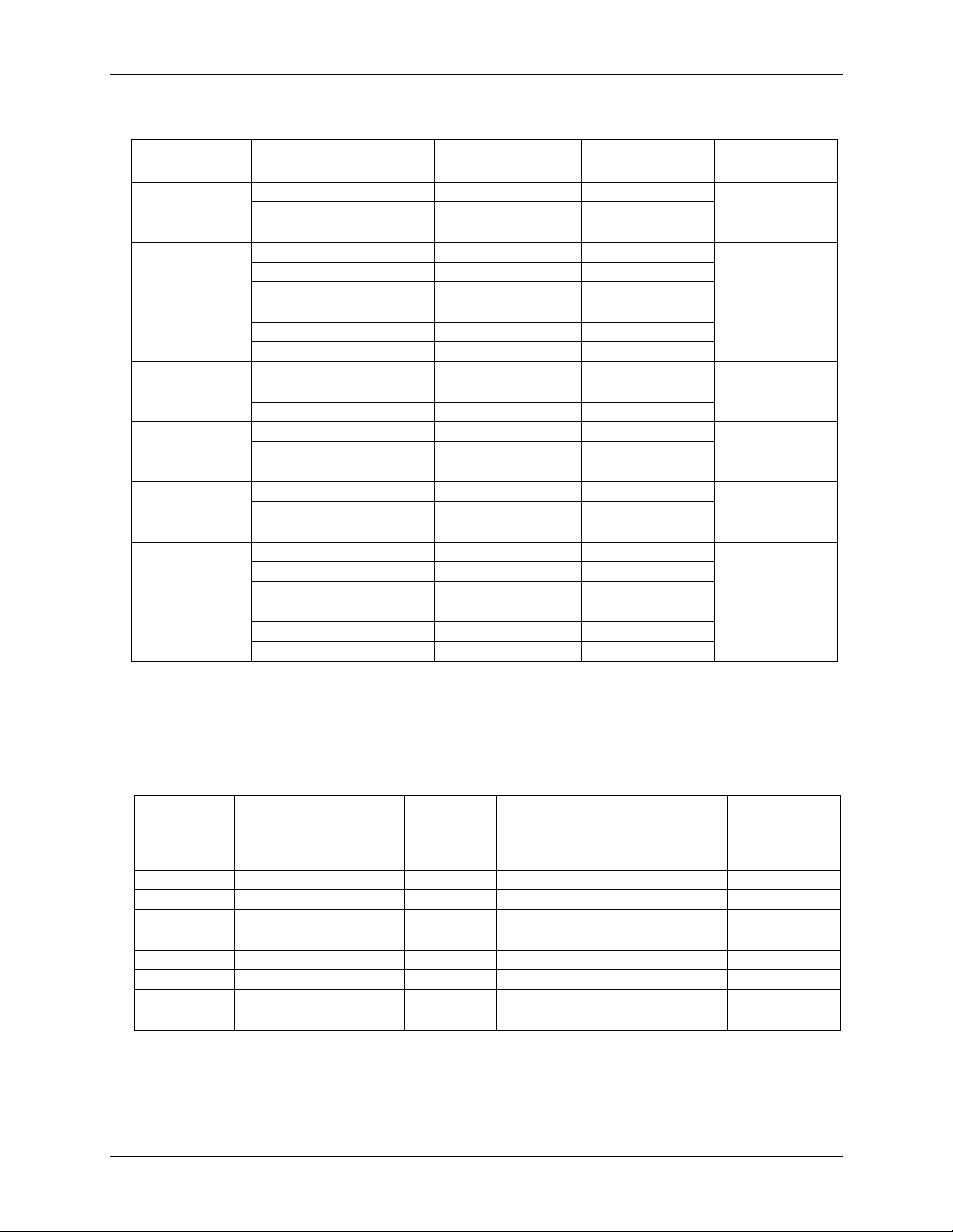
Accuracy
Thermocouple measurement accuracy
Thermocouple measurement accuracy specifications include polynomial linearization error, cold-junction
compensation measurement error, and are for sample rates up to 60S/s. These specs are for one year, or 3000
operating hours, whichever comes first.
There is a CJC sensor for each terminal block of the module. The accuracy listed below assumes the screw
terminals are at the same temperature as the CJC sensor.
The accuracy errors shown do not include the inherent accuracy error of the thermocouple sensor itself. Contact
your thermocouple supplier for details on the actual thermocouple sensor accuracy limitations.
Connect thermocouples to the USB-2408 Series device such that they are floating with respect to AGND .
When configuring thermocouple sensors, keep any stray capacitance relative to AGND as small as possible to
avoid settling time and accuracy errors.
The AGND and DGND pins are isolated from earth ground. You can connect thermocouple sensors to voltages
referenced to earth ground as long as isolation between the AGND/DGND pins and earth ground is maintained.
22
Page 23
USB-2408 Series User's Guide Specifications
Thermocouple
Sensor temperature
range
Accuracy error,
maximum
Accuracy error,
typical
Tempco
(°C/°C)
J
–210 °C
2.572 °C
1.416 °C
0.022
0 °C
0.935 °C
0.469 °C
1200 °C
1.869 °C
1.456 °C
K
–210 °C
2.917 °C
1.699 °C
0.029
0 °C
1.017 °C
0.526 °C
1372 °C
2.478 °C
2.022 °C
N
–200 °C
3.480°C
2.030 °C
0.029
0 °C
1.201 °C
0.659 °C
1300 °C
1.991 °C
1.600 °C
R
–50 °C
4.826 °C
3.133 °C
0.082
250 °C
2.117 °C
1.424 °C
1768 °C
2.842 °C
2.347 °C
S
–50 °C
4.510 °C
2.930 °Co
.089
250 °C
2.165 °C
1.468 °C
1768 °C
3.187 °C
2.597 °C
B
250 °C
5.489 °C
3.956 °C
0.14
700 °C
2.283 °C
1.743 °C
1820 °C
2.202 °C
1.842 °C
E
–200 °C
2.413 °C
1.352 °C
0.017
0 °C
1.069 °C
0.551 °C
1000 °C
1.575 °C
1.211 °C
T
–200 °C
2.821 °C
1.676 °C
0.027
0 °C
1.050 °C
0.558 °C
400 °C
0.957 °C
0.595 °C
Range
Gain error (%
of reading)
Offset
error
INL error (%
of range)
Absolute
accuracy
Gain temperature
coefficient
(% reading/°C)
Offset
temperature
coefficient
(µV/°C)
±10 V
0.0037
50 µV
0.0008
500 µV
0.0006
3
±5 V
0.0047
25 µV
0.0008
300 µV
0.0006
2
±2.5 V
0.0059
20 µV
0.0008
200 µV
0.0006
1
±1.25 V
0.0056
20 µV
0.0008
100 µV
0.0006
1
±0.625 V
0.0068
15 µV
0.0005
60 µV
0.0006
1
±0.3125 V
0.0104
15 µV
0.0006
50 µV
0.0006
1
±0.15625 V
0.0184
10 µV
0.0005
40 µV
0.0006
1
±0.078125 V
0.0384
10 µV
0.0009
40 µV
0.0006
1
Table 4. Thermocouple accuracy specifications, including CJC measurement error.
All specifications are (±).
To achieve the thermocouple accuracies listed above, warm up the USB-2408 Series device for 45 minutes after
the initial power on. The accuracies listed above are only guaranteed if the device is housed in the plastic
enclosure.
Analog input DC voltage measurement accuracy
Table 5. DC Accuracy components and specifications. All values are (±)
23
Page 24
USB-2408 Series User's Guide Specifications
A/D data rate
–3 db Bandwidth (Hz)
3750 S/s
1615
2000 S/s
878
1000 S/s
441
500 S/s
221
100 S/s
44.2
60 S/s
26.5
50 S/s
22.1
25 S/s
11.1
10 S/s
4.42
5 S/s
2.21
2.5 S/s
1.1
A/D data rate
Range
3750 S/s
2000 S/s
1000 S/s
500 S/s
100 S/s
60 S/s
50 S/s
25 S/s
10 S/s
5 S/s
2.5 S/s
±10 V
126.84
100.14
71.76
45.06
30.52
30.52
26.70
19.07
11.92
9.54
9.54
±5 V
56.74
47.56
34.21
25.87
16.21
14.31
14.31
14.30
5.96
4.77
4.77
±2.5 V
32.96
28.79
17.94
14.19
7.51
7.09
7.09
5.72
3.81
4.00
4.00
±1.25 V
18.57
17.52
13.83
9.30
5.48
5.48
5.01
3.81
3.34
3.34
2.86
±0.625 V
18.88
16.58
8.45
7.41
5.32
4.80
4.38
3.86
2.50
2.61
1.98
±0.3125 V
15.33
14.76
8.19
6.94
4.75
4.69
4.49
3.70
3.34
2.56
2.45
±0.15625 V
13.28
16.84
7.47
6.61
5.70
4.48
4.48
4.24
2.66
3.07
2.29
±0.078125 V
13.47
15.02
9.17
6.88
4.28
4.16
4.00
3.57
2.28
2.13
2.40
A/D data rate
Range
3750 S/s
2000 S/s
1000 S/s
500 S/s
100 S/s
60 S/s
50 S/s
25 S/s
10 S/s
5 S/s
2.5 S/s
±10 V
19.22
15.17
10.87
6.83
4.62
4.62
4.05
2.89
1.81
1.44
1.44
±5 V
8.60
7.21
5.18
3.92
2.46
2.17
2.17
2.16
0.90
0.72
0.72
±2.5 V
4.99
4.36
2.72
2.15
1.14
1.07
1.07
0.87
0.58
0.60
0.60
±1.25 V
2.81
2.66
2.10
1.41
0.83
0.83
0.76
0.58
0.51
0.51
0.43
±0.625 V
2.86
2.51
1.28
1.12
0.81
0.73
0.66
0.58
0.38
0.40
0.30
±0.3125 V
2.32
2.24
1.24
1.05
0.72
0.71
0.68
0.56
0.51
0.39
0.37
±0.15625 V
2.01
2.55
1.13
1.00
0.86
0.68
0.68
0.64
0.40
0.47
0.35
±0.078125 V
2.04
2.28
1.39
1.04
0.65
0.63
0.60
0.54
0.35
0.32
0.36
Input bandwidth
Table 6. input bandwidth
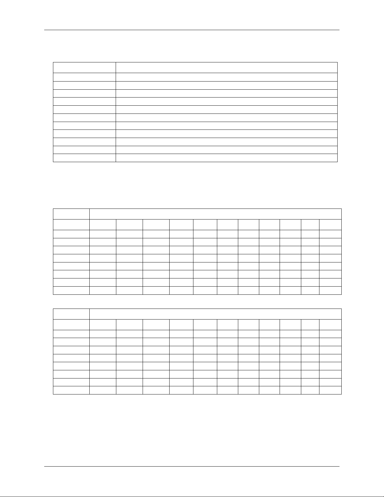
Noise performance
For the peak-to-peak noise distribution test, a differential input channel is connected to AGND at the input
terminal block, and 50,000 samples are acquired at the maximum rate available at each setting.
Table 7. Peak-to-peak noise performance specifications (µV)
Table 8. RMS noise performance specifications (µVRMS)
24
Page 25
USB-2408 Series User's Guide Specifications
A/D data rate
Range
3750 S/s
2000 S/s
1000 S/s
500 S/s
100 S/s
60 S/s
50 S/s
25 S/s
10 S/s
5 S/s
2.5 S/s
±10 V
17.2
17.6
18.1
18.7
19.3
19.3
19.5
20.0
20.6
21.0
21.0
±5 V
17.4
17.6
18.1
18.5
19.2
19.4
19.4
19.4
20.6
21.0
21.0
±2.5 V
17.2
17.4
18.1
18.4
19.3
19.4
19.4
19.7
20.3
20.7
21.0
±1.25 V
17.0
17.1
17.4
18.0
18.8
18.8
18.9
19.3
19.5
19.5
19.7
±0.625 V
16.0
16.2
17.1
17.3
17.8
18.0
18.1
18.3
18.9
18.8
19.2
±0.3125 V
15.3
15.3
16.2
16.4
17.0
17.0
17.0
17.3
17.5
17.9
17.9
±0.15625 V
14.5
14.1
15.3
15.5
15.7
16.1
16.1
16.1
16.8
16.9
17.1
±0.078125 V
14.5
14.3
15.0
15.4
16.1
16.2
16.2
16.4
17.0
17.1
16.9
Accuracy
Range
3750 S/s
2000 S/s
1000 S/s
500 S/s
100 S/s
60 S/s
50 S/s
25 S/s
10 S/s
5 S/s
2.5 S/s
±10 V
0.0010%
0.0008%
0.0005%
0.0004%
0.0002%
0.0002%
0.0003%
0.0002%
0.0001%
0.0001%
0.0001%
±5 V
0.0009%
0.0008%
0.0004%
0.0004%
0.0003%
0.0002%
0.0002%
0.0002%
0.0001%
0.0001%
0.0001%
±2.5 V
0.0010%
0.0007%
0.0008%
0.0004%
0.0003%
0.0002%
0.0002%
0.0002%
0.0002%
0.0001%
0.0001%
±1.25 V
0.0013%
0.0009%
0.0008%
0.0007%
0.0004%
0.0004%
0.0003%
0.0003%
0.0003%
0.0003%
0.0003%
±0.625 V
0.0022%
0.0016%
0.0011%
0.0011%
0.0007%
0.0007%
0.0005%
0.0005%
0.0004%
0.0005%
0.0003%
±0.3125 V
0.0031%
0.0031%
0.0020%
0.0017%
0.0015%
0.0012%
0.0010%
0.0010%
0.0012%
0.0009%
0.0009%
±0.15625 V
0.0056%
0.0062%
0.0048%
0.0037%
0.0032%
0.0025%
0.0024%
0.0021%
0.0019%
0.0022%
0.0016%
±0.078125 V
0.0114%
0.0123%
0.0076%
0.0070%
0.0041%
0.0051%
0.0046%
0.0036%
0.0032%
0.0030%
0.0034%
A/D data rate
Maximum throughput (Hz)
3750 S/s
1102.94
2000 S/s
877.19
1000 S/s
609.76
500 S/s
378.79
100 S/s
93.98
60 S/s
57.78
50 S/s
48.45
25 S/s
24.61
10 S/s
9.94
5 S/s
4.98
2.5 S/s
2.50
Table 9. Noise-free resolution specifications (bits)
Channel switching error
Table 10. Step response accuracy specifications
Channel switching error is defined as the accuracy that can be expected after one conversion when switching
from a channel with a DC input at one extreme of full scale to another channel with a DC input at the other
extreme of full scale, expressed in terms of percentage of full scale value.
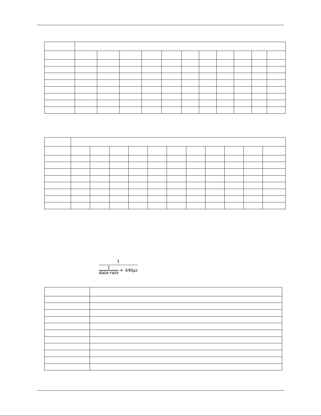
Throughput rate
The single channel throughput rate is calculated using this formula:
Maximum throughput =
Table 11. Single channel throughput rate specifications
25
Page 26

USB-2408 Series User's Guide Specifications
Number
of input
channels
3750 S/s
2000 S/s
1000 S/s
500 S/s
100 S/s
60 S/s
50 S/s
25 S/s
10 S/s
5 S/s
2.5 S/s
1
1102.94
877.19
609.76
378.79
93.98
57.78
48.45
24.61
9.94
4.98
2.50 2 551.47
438.60
304.88
189.39
46.99
28.89
24.22
12.30
4.97
2.49
1.25 3 367.65
292.40
203.25
126.26
31.33
19.26
16.15
8.20
3.31
1.66
0.83 4 275.74
219.30
152.44
94.70
23.50
14.45
12.11
6.15
2.48
1.25
0.62 5 220.59
175.44
121.95
75.76
18.80
11.56
9.69
4.92
1.99
1.00
0.50 6 183.82
146.20
101.63
63.13
15.66
9.63
8.07
4.10
1.66
0.83
0.42 7 157.56
125.31
87.11
54.11
13.43
8.25
6.92
3.52
1.42
0.71
0.36
8
137.87
109.65
76.22
47.35
11.75
7.22
6.06
3.08
1.24
0.62
0.31
9
122.55
97.47
67.75
42.09
10.44
6.42
5.38
2.73
1.10
0.55
0.28
10
110.29
87.72
60.98
37.88
9.40
5.78
4.84
2.46
0.99
0.50
0.25
11
100.27
79.74
55.43
34.44
8.54
5.25
4.40
2.24
0.90
0.45
0.23
12
91.91
73.10
50.81
31.57
7.83
4.82
4.04
2.05
0.83
0.42
0.21
13
84.84
67.48
46.90
29.14
7.23
4.44
3.73
1.89
0.76
0.38
0.19
14
78.78
62.66
43.55
27.06
6.71
4.13
3.46
1.76
0.71
0.36
0.18
15
73.53
58.48
40.65
25.25
6.27
3.85
3.23
1.64
0.66
0.33
0.17
16
68.93
54.82
38.11
23.67
5.87
3.61
3.03
1.54
0.62
0.31
0.16
Parameter
Conditions
Specifications
Digital-to-analog
converter
DAC8552
Number of channels
2 Resolution
16 bits
Output ranges
Calibrated
±10 V
Uncalibrated
±10.05 V (software-selectable)
Output transient
Host PC is reset, powered on, suspended or a reset
command is issued to device
Duration: 2 s
Amplitude: 2 V p-p
Initial power on
Duration: 50 ms
Amplitude: 5 V peak
Differential non-linearity
±0.25 LSB typ
±1 LSB max
Output current
AOUTx pins
±5.0 mA max
Output short-circuit
protection
AOUTx connected to AGND
Unlimited duration
Output coupling
DC
The multiple-channel throughput rate is calculated using this formula:
Maximum throughput = , where n is the number of channels
Table 12. Multiple-channel throughput rate specifications (Hz)
Analog voltage output (USB-2408-2AO only)
Unused AOUTx output channels should be left disconnected.
The USB-2408-2AO output voltage level defaults to 0 V whenever the host PC is reset, shut down or
suspended, or if a reset command is issued to the device.
The outputs may have a transient during startup. The duration of the output transient depends highly on the
enumeration process of the host PC. Typically, the output of the USB-2408-2AO is stable after two seconds.
Table 13. USB-2408-2AO analog voltage output specifications
26
Page 27

USB-2408 Series User's Guide Specifications
Parameter
Conditions
Specifications
Power on and reset state
DACs cleared to zero-scale: 0 V,
±50 mV
Output noise
60 µV
rms
(BW=1.5 KHz)
Settling time
To rated accuracy, 10 V step
75 µS
Slew rate
1.0 V/µs
Throughput
Single-channel
1000 S/s max, system-dependent,
0.01 S/s min
Multi-channel
1000 S/s / #ch max, systemdependent, 0.01 S/s min
Range
Accuracy (±LSB)
±10 V
16.0
Range
% of reading
Offset (±mV)
Temp drift (%/°C)
Absolute accuracy at FS (±mV)
±10 V
±0.0183
1.831
0.00055
3.661
Range
Relative accuracy (±LSB)
±10 V
4.0 typ
Parameter
Specifications
Recommended warm-up time
45 minutes min
Calibration
Firmware calibration
Calibration interval
1 year
AI calibration reference
+10.000 V, ±5 mV max. Actual measured values stored in EEPROM
Tempco: 5 ppm/°C max
Long term stability: 30 ppm/1000 hours
AO calibration procedure
(USB-2408-2AO only)
The analog output pin is internally routed to the analog input pin.
AOUTx readback
(USB-2408-2AO only)
Each AOUTx output can be independently measured by the onboard A/D converter.
Software-selectable
Table 14. Calibrated absolute accuracy specifications
Table 15. Calibrated absolute accuracy components specifications
Table 16. Relative accuracy specifications
Analog input/output calibration
Table 17. Analog input/output calibration specifications
27
Page 28

USB-2408 Series User's Guide Specifications
Parameter
Specifications
Number of I/O
8 channels
Configuration
Each DIO bit can be independently read from (DIN) or written to (DOUT).
The DIN bits can be read at any time whether the DOUT is active or tri-stated.
Input voltage range
0 to +15 V
Input type
CMOS (Schmitt trigger)
Input characteristics
47 kΩ pull-up/pull-down resistor, 28 kΩ series resistor
Maximum input voltage range
0 V to +20 V max (power on/off, relative to DGND) (Note 2)
Pull-up/pull-down
configuration
All pins pulled up to +5 V via individual 47 kΩ resistors (the J6 shorting block default
position is pins 1 and 2).
Pull down capability is available by placing the J6 shorting block across pins 2 and 3.
Transfer rate (software paced)
500 port reads or single bit reads per second typ.
Input high voltage
1.3 V min, 2.2 V max
Input low voltage
1.5 V max, 0.6 V min
Schmitt trigger hysteresis
0.4 V min, 1.2 V max
Parameter
Specifications
Number of I/O
8 channels
Configuration (Note3)
Each DIO bit can be independently read from (DIN) or written to (DOUT).
The DIN bits may be read at any time whether the DOUT is active or tri-stated
Output characteristics (Note 4)
47 kΩ pull-up, open drain (DMOS transistor)
Pull-up configuration
All pins pulled up to +5 V via individual 47 kΩ resistors (the J6 shorting block default
position is pins 1 and 2).
Transfer rate (software paced)
Digital output – 500 port writes or single-bit writes per second typ.
Output voltage range
0 V to +5 V (no external pull up resistor, internal 47 kΩ pull-up resistors connected to
+5 V by default)
0 V to +15 V max (Note 5)
Drain to source breakdown
voltage
+50 V min
Off state leakage current
(Note 6)
1.0 µA
Sink current capability
150 mA max (continuous) per output pin
150 mA max (continuous) for all eight channels
DMOS transistor on-resistance
(drain to source)
4 Ω
Digital input/output
Table 18. Digital input specifications
Note 2: DGND pins are recommended for use with digital input and digital output pins. The DGND and
AGND pins are common and are isolated from earth ground.
Table 19. Digital output specifications
Note 3: DGND pins are recommended for use with digital input and digital output pins. The DGND and
AGND pins are common and are isolated from earth ground.
Note 4: Each DMOS transistor source pin is internally connected to DGND.
Note 5: The external pull-up is connected to the digital output bit through an external pull-up resistor. Adding
an external pull-up resistor connects it in parallel with the internal 47 kΩ pull-up resistor of that
particular digital input/output bit. Careful consideration should be made when considering the external
pull-up resistor value and the resultant pull-up voltage produced at the load.
Note 6: Does not include the additional leakage current contribution that may occur when using an external
pull-up resistor.
28
Page 29

USB-2408 Series User's Guide Specifications
Parameter
Conditions
Specification
Pin name
CTR0, CTR1
Number of channels
2 channels
Resolution
32-bits
Counter type
Event counter
Input type
Schmitt trigger, rising edge triggered
Input source
CTR0 (pin 44)
CTR1 (pin 42)
Counter read/writes rates
(software paced)
Counter read
System dependent, 500 reads per second.
Counter write
System dependent, 500 writes per second.
Input characteristics
Each CTRx input pin
562 kΩ pull-up resistor to +5 V, 10 kΩ series
resistor
Input voltage range
±15 V max
Max input voltage range
CTR0,CTR1 relative to AGND
and DGND (Note 7)
±20 V max (power on/off)
Input high voltage
1.3 V min, 2.2 V max
Input low voltage
1.5 V max, 0.6 V min
Schmitt trigger hysteresis
0.4 V min, 1.2 V max
Input bandwidth (–3 dB)
1 MHz
Input capacitance
25 pf
Input leakage current
±120 nA@5 V, ±1.6 mA@±15 V
Input frequency
1 MHz, max
High pulse width
500 ns, min
Low pulse width
500 ns, min
EEPROM
4096 bytes isolated micro reserved for sensor configuration
256 bytes USB micro for external application use
Type
One high-performance 8-bit RISC microcontroller with USB interface (non-isolated)
One high-performance 16-bit RISC microcontroller for measurements (isolated)
Counter
Table 20. CTR specifications
Note 7: DGND pins are recommended for use with counter input pins. The DGND and AGND are common
and are isolated from earth ground.
Memory
Table 21. Memory specifications
Microcontroller
Table 22. Microcontroller specifications
29
Page 30

USB-2408 Series User's Guide Specifications
Parameter
Conditions
Specification
Supply current (Note 8)
Quiescent current
275 mA
Voltage supervisor limits
4.5 V > V
ext
or V
ext
> 5.5 V
PWR LED = Off; (power fault)
4.5 V < V
ext
< 5.5 V
PWR LED = On
+5 V user output voltage range
Available at terminal block pin 40
4.75 V min to 5.25 V max
+5 V user output current
Available at terminal block pin 40
10 mA max
Isolation
Measurement system to PC
500 VDC min
Parameter
Specifications
USB device type
USB 2.0 (full-speed)
Device compatibility
USB 1.1, USB 2.0
USB cable type
A-B cable, UL type AWM 2527 or equivalent. (min 24 AWG VBUS/GND,
min 28 AWG D+/D–)
USB cable length
3 meters max
Parameter
Specifications
Operating temperature range
0 °C to 50 °C max
Storage temperature range
–40 °C to 85 °C max
Humidity
0 to 90% non-condensing max
Parameter
Specifications
Dimensions (L x W x H)
127 89.9 35.6 mm (5.00 x 3.53 x 1.40 in.)
User connection length
3 meters max
Connector type
Fixed screw terminal
Wire gauge range
16 AWG to 30 AWG
Power
Table 23. Power specifications
Note 8: This is the total quiescent current requirement for the USB-2408 Series which includes up to 10 mA
for the status LED. This does not include any potential loading of the digital I/O bits, +5 V user
terminal or the AOUTx outputs.
USB specifications
Table 24. USB specifications
Environmental
Table 25. Environmental specifications
Mechanical
Table 26. Mechanical specifications
Screw terminal connector type and pinout
Table 27. Screw terminal connector specifications
30
Page 31

USB-2408 Series User's Guide Specifications
Pin
Signal name
Pin description
Pin
Signal name
Pin description
1
CH0H
Channel 0 HI
23
AGND
Analog ground
2
CH0L
Channel 0 LO
24
CH7L
Channel 7 LO
3
AGND
Analog ground
25
CH7H
Channel 7 HI
4
CH1H
Channel 1 HI
26
AGND
Analog ground
5
CH1L
Channel 1 LO
27
CH6L
Channel 6 LO
6
AGND
Analog ground
28
CH6H
Channel 6 HI
7
CH2H
Channel 2 HI
29
AGND
Analog ground
8
CH2L
Channel 2 LO
30
CH5L
Channel 5 LO
9
AGND
Analog ground
31
CH5H
Channel 5 HI
10
CH3H
Channel 3 HI
32
AGND
Analog ground
11
CH3L
Channel 3 LO
33
CH4L
Channel 4 LO
12
AGND
Analog ground
34
CH4H
Channel 4 HI
13
DGND
Digital ground
35
AGND
Analog ground
14
DIO0
Digital input/output
36
AOUT1 (Note 9)
Analog output 1
15
DIO1
Digital input/output
37
AGND
Analog ground
16
DIO2
Digital input/output
38
AOUT0 (Note 9)
Analog output 0
17
DIO3
Digital input/output
39
CHAS
Chassis ground
18
DIO4
Digital input/output
40
+5V
+5 V output
19
DIO5
Digital input/output
41
DGND
Digital ground
20
DIO6
Digital input/output
42
CTR1
Counter 1
21
DIO7
Digital input/output
43
DGND
Digital ground
22
DGND
Digital ground
44
CTR0
Counter 0
Screw terminal pinout
Table 28. 8-channel differential mode pinout
Note 9: On the USB-2408, these pins are labeled NC (no connection).
31
Page 32

USB-2408 Series User's Guide Specifications
Pin
Signal name
Pin description
Pin
Signal name
Pin description
1
CH0
Channel 0
23
AGND
Analog ground
2
CH8
Channel 8
24
CH15
Channel 15
3
AGND
Analog ground
25
CH7
Channel 7
4
CH1
Channel 1
26
AGND
Analog ground
5
CH9
Channel 9
27
CH14
Channel 14
6
AGND
Analog ground
28
CH6
Channel 6
7
CH2
Channel 2
29
AGND
Analog ground
8
CH10
Channel 10
30
CH13
Channel 13
9
AGND
Analog ground
31
CH5
Channel 5
10
CH3
Channel 3
32
AGND
Analog ground
11
CH11
Channel 11
33
CH12
Channel 12
12
AGND
Analog ground
34
CH4
Channel 4
13
DGND
Digital ground
35
AGND
Analog ground
14
DIO0
Digital input/output
36
AOUT1 (Note 10)
Analog output 1
15
DIO1
Digital input/output
37
AGND
Analog ground
16
DIO2
Digital input/output
38
AOUT0 (Note 10)
Analog output 0
17
DIO3
Digital input/output
39
CHAS
Chassis ground
18
DIO4
Digital input/output
40
+5V
+5 V output
19
DIO5
Digital input/output
41
DGND
Digital ground
20
DIO6
Digital input/output
42
CTR1
Counter 1
21
DIO7
Digital input/output
43
DGND
Digital ground
22
DGND
Digital ground
44
CTR0
Counter 0
Table 29. 16-channel single-ended mode pinout
Note 10: On the USB-2408, these pins are labeled NC (no connection).
32
Page 33

Declaration of Conformity
Manufacturer: Measurement Computing Corporation
Address: 10 Commerce Way
Suite 1008
Norton, MA 02766
USA
Category: Electrical equipment for measurement, control and laboratory use.
Measurement Computing Corporation declares under sole responsibility that the products
USB-2408, USB-2408-2AO
to which this declaration relates is in conformity with the relevant provisions of the following standards or other
documents:
EC EMC Directive 2004/108/EC: General Requirements, EN 61326-1:2006 (IEC 61326-1:2005).
Emissions:
EN 55011 (2007) / CISPR 11(2003): Radiated emissions: Group 1, Class A
EN 55011 (2007) / CISPR 11(2003): Conducted emissions: Group 1, Class A
Immunity: EN 61326-1:2006, Table 3.
IEC 61000-4-2 (2001): Electrostatic Discharge immunity.
IEC 61000-4-3 (2002): Radiated Electromagnetic Field immunity.
To maintain compliance to the standards of this declaration, the following conditions must be met.
The host computer, peripheral equipment, power sources, and expansion hardware must be CE compliant.
All I/O cables must be shielded, with the shields connected to ground.
I/O cables must be less than 3 meters (9.75 feet) in length.
The host computer must be properly grounded.
The host computer must be USB 2.0 compliant.
Equipment must be operated in a controlled electromagnetic environment as defined by Standards EN
61326-1:2006, or IEC 61326-1:2005.
Note: Data acquisition equipment may exhibit noise or increased offsets when exposed to high RF fields
(>1V/m) or transients.
Declaration of Conformity based on tests conducted by Chomerics Test Services, Woburn, MA 01801, USA in
November, 2010. Test records are outlined in Chomerics Test Report #EMI5755.10.
We hereby declare that the equipment specified conforms to the above Directives and Standards.
Carl Haapaoja, Director of Quality Assurance
Page 34

Measurement Computing Corporation
10 Commerce Way
Suite 1008
Norton, Massachusetts 02766
(508) 946-5100
Fax: (508) 946-9500
E-mail: info@mccdaq.com
www.mccdaq.com
 Loading...