

Page 1

USB-2020
User's Guide
12-bit, Ultra High-Speed USB Device
Document Revision 2
February 2015
© Copyright 2015
Page 2

Your new Measurement Computing product comes with a fantastic extra —
Management committed to your satisfaction!
Thank you for choosing a Measurement Computing product—and congratulations! You own the finest, and you can now enjoy
the protection of the most comprehensive warranties and unmatched phone tech support. It’s the embodiment of our mission:
To provide data acquisition hardware and software that will save time and save money.
Simple installations minimize the time between setting up your system and actually making measurements. We offer quick and
simple access to outstanding live FREE technical support to help integrate MCC products into a DAQ system.
Limited Lifetime Warranty : Most MCC products are covered by a limited lifetime warranty against defects in materials or
workmanship for the life of the product, to the original purchaser, unless otherwise noted. Any products found to be defective in
material or workmanship will be repaired, replaced with same or similar device, or refunded at MCC’s discretion. For specific
information, please refer to the terms and conditions of sale.
Harsh Environment Program: Any Measurement Computing product that is damaged due to misuse, or any reason, may be
eligible for replacement with the same or similar device for 50% of the current list price. I/O boards face some harsh
environments, some harsher than the boards are designed to withstand. Contact MCC to determine your product’s eligibility for
this program.
30 Day Money-Back Guarantee: Any Measurement Computing Corporation product may be returned within 30 days of
purchase for a full refund of the price paid for the product being returned. If you are not satisfied, or chose the wrong product by
mistake, you do not have to keep it.
These warranties are in lieu of all other warranties, expressed or implied, including any implied warranty of merchantability or
fitness for a particular application. The remedies provided herein are the buyer’s sole and exclusive remedies. Neither
Measurement Computing Corporation, nor its employees shall be liable for any direct or indirect, special, incidental or
consequential damage arising from the use of its products, even if Measurement Computing Corporation has been notified in
advance of the possibility of such damages.
Trademark and Copyr ight Info rmation
Measurement Computing Corporation, InstaCal, Universal Library, and the Measurement Computing logo are either trademarks
or registered trademarks of Measurement Computing Corporation. Refer to the Copyrights & Trademarks section on
mccdaq.com/legal for more information about Measurement Computing trademarks. Other product and company names
mentioned herein are trademarks or trade names of their respective companies.
© 2015 Measurement Computing Corporation. All rights reserved. No part of this publication may be reproduced, stored in a
retrieval system, or transmitted, in any form by any means, electronic, mechanical, by photocopying, recording, or otherwise
without the prior written permission of Measurement Computing Corporation.
Notice
Measurement Computing Corporation does not authorize any Measurement Computing Corporation product for use
in life support systems and/or devices without prior written consent from Measurement Computing Corporation.
Life support devices/systems are devices or systems that, a) are intended for surgical implantation into the body, or
b) support or sustain life and whose failure to perform can be reasonably expected to result in injury. Measurement
Computing Corporation products are not designed with the components required, and are not subject to the testing
required to ensure a level of reliability suitable for the treatment and diagnosis of people.
HM USB-2020
Page 3

Table of Contents
Preface
About this User's Guide ....................................................................................................................... 5
What you will learn from this user's guide ......................................................................................................... 5
Conventions in this user's guide ......................................................................................................................... 5
Where to find more information ......................................................................................................................... 5
Chapter 1
Introducing the USB-2020 .................................................................................................................... 6
Functional block diagram ................................................................................................................................... 6
Chapter 2
Installing the USB-2020 ........................................................................................................................ 7
What comes with your USB-2020 shipment? ..................................................................................................... 7
Hardware .......................................................................................................................................................................... 7
Software ............................................................................................................................................................................ 7
Documentation .................................................................................................................................................................. 7
Optional components ........................................................................................................................................................ 7
Unpacking........................................................................................................................................................... 7
Installing the software ........................................................................................................................................ 7
Installing the hardware ....................................................................................................................................... 8
Connecting the external power supply .............................................................................................................................. 8
Calibrating the hardware..................................................................................................................................... 9
Connecting the board for I/O operations ............................................................................................................ 9
Connectors, cables, and accessory products ...................................................................................................................... 9
Cabling ............................................................................................................................................................. 10
Field wiring, signal termination and conditioning ...........................................................................................................10
Chapter 3
Functional Details ............................................................................................................................... 11
Analog input acquisition modes ....................................................................................................................... 11
Software paced .................................................................................................................................................................11
Continuous scan (hardware paced) ..................................................................................................................................11
BURSTIO ........................................................................................................................................................................11
Connectors and LEDs ....................................................................................................................................... 12
BNC connectors ...............................................................................................................................................................12
Status LEDs .....................................................................................................................................................................12
USB connector .................................................................................................................................................................12
External power connector ................................................................................................................................................12
40-pin auxiliary connector (J9) ........................................................................................................................................13
Signal connections ............................................................................................................................................ 14
Analog input ....................................................................................................................................................................14
External clock I/O ............................................................................................................................................................15
Digital I/O ........................................................................................................................................................................15
Trigger input ....................................................................................................................................................................16
Mechanical drawing ......................................................................................................................................... 17
Chapter 4
Specifications ...................................................................................................................................... 18
Analog input ..................................................................................................................................................... 18
Accuracy ..........................................................................................................................................................................19
Noise performance ...........................................................................................................................................................19
Analog input calibration ................................................................................................................................... 19
Digital input/output........................................................................................................................................... 20
External trigger ................................................................................................................................................. 21
3
Page 4

USB-2020 User's Guide
External clock input/output............................................................................................................................... 21
Memory ............................................................................................................................................................ 21
Power ................................................................................................................................................................ 22
Environmental .................................................................................................................................................. 22
Mechanical ....................................................................................................................................................... 22
USB .................................................................................................................................................................. 22
Signal I/O connectors ....................................................................................................................................... 23
BNC connectors ...............................................................................................................................................................23
Auxiliary connector .........................................................................................................................................................23
4
Page 5

About this User's Guide
What you will learn from this user's guide
This user's guide describes the Measurement Computing USB-2020 data acquisition device and lists device
specifications.
Conventions in this user's guide
For more information
Text presented in a box signifies additional information and helpful hints related to the subject matter you are
reading.
Caution! Shaded caution statements present information to help you avoid injuring yourself and others,
damaging your hardware, or losing your data.
bold text Bold text is used for the names of objects on a screen, such as buttons, text boxes, and check boxes.
italic text Italic text is used for the names of manuals and help topic titles, and to emphasize a word or phrase.
Preface
Where to find more inf orm a ti on
Additional information about the USB-2020 is available on our website at www.mccdaq.com. You can also
contact Measurement Computing Corporation by phone, fax, or email with specific questions.
Knowledgebase:
Phone: 508-946-5100 and follow the instructions for reaching Tech Support
Fax: 508-946-9500 to the attention of Tech Support
Email:
techsupport@mccdaq.com
kb.mccdaq.com
5
Page 6
Chapter 1
Introducing the USB-2020
The USB-2020 is a high-speed data acquisition USB board supported under the Windows® operating system.
The USB-2020 is compatible with both USB 1.1 and USB 2.0 ports. The speed of the device may be limited
when using a USB 1.1 port due to the difference in transfer rates on the USB 1.1 versions of the protocol (lowspeed and full-speed).
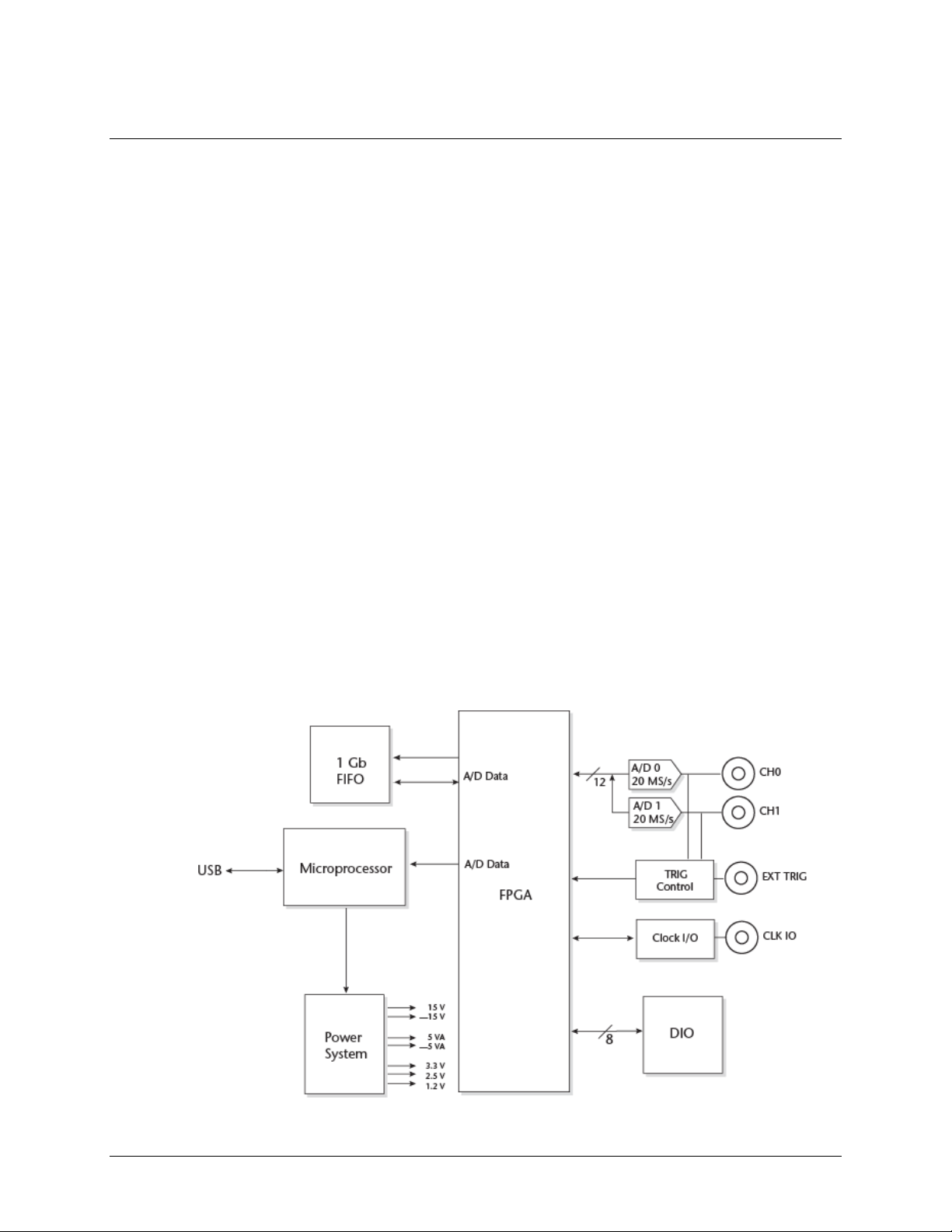
The USB-2020 device provides the following features:
two 20 MS/s analog inputs
o simultaneous sampling
o 1 A/D per channel
o 12-bit resolution
o ±10 V, ±5 V, ±2 V, ±1 V voltage ranges (software-selectable)
o 17 MHz input bandwidth
64 megasample onboard memory
o 40 MS/s overall rate to onboard memory when acquiring from both channels (20 MS/s per channel)
o 8 MS/s throughput to host computer
Analog and digital triggering (level and edge )
Analog and digital gating
Eight digital I/O lines
Internal or external pacing of analog scans
Eight digital I/O lines
BNC connectors and 40-pin auxiliary connector for signal connections
Functional block diagram
USB-2020 functions are illustrated in the block diagram shown here.
Figure 1. Functional block diagr am
6
Page 7

Chapter 2
Installing the USB-2020
What comes with your USB-2020 shipment?
Hardware
USB-2020
USB cable (2-meter length)
External power supply and cord: 9 VDC, 3 A power adapter. MCC part number CB-PWR-9
Four nylon standoffs
Software
MCC DAQ Software CD
Documentation
MCC DAQ Quick Start Guide
The Quick Start Guide booklet provides an overview of the MCC DAQ software you received with the device,
and includes information about installing the software. Please read this booklet completely before installing any
software or hardware.
Optional components
Cables
o Standard BNC cable
o C40FF-x
o C40-37F-x
Screw termination boards
o CIO-MINI40
o CIO-MINI37
o SCB-37
Unpacking
As with any electronic device, you should take care while handling to avoid damage from static
electricity. Before removing the USB-2020 from its packaging, ground yourself using a wrist strap or by simply
touching the computer chassis or other grounded object to eliminate any stored static charge.
If your USB-2020 arrives already damaged, notify Measurement Computing Corporation immediately by
phone, fax, or email.
Knowledgebase:
Phone
Fax: 508-946-9500 to the attention of Tech Support
Email:
For
website at
: 508-946-5100 and follow the instructions for reaching Tech Support
techsupport@mccdaq.com
international customers, contact your local distributor. Refer to the International Distributors section on our
www.mccdaq.com/International.
kb.mccdaq.com
Installing the software
Refer to the Quick Start Guide for instructions on installing the software on the MCC DAQ CD. This booklet is
available in PDF at
www.mccdaq.com/PDFmanuals/DAQ-Software-Quick-Start.pdf.
7
Page 8

USB-2020 User's Guide Installing the USB-2020
Installing the hardware
Before you connect the USB-2020 to your computer, connect the external power supply that was shipped with
the device.
Disconnect USB, then power supply
When disconnecting the USB-2020, disconnect the USB cable first, and then disconnect the power supply.
Connecting the external power supply
Refer to Figure 8 on page 12 for the location of the connectors and LEDs mentioned in the following procedure.
Power to the USB-2020 is provided with the 9 VDC external power supply (CB-PWR-9). Connect the external
power supply before connecting the USB cable to the USB-2020 and your computer.
Complete the following steps to connect the power supply to the USB-2020:
1. Connect the external power cord to the USB-2020-power connector.
2. Plug the power supply into a power outlet.
The top (
is established. If the voltage supply is less than 7.3 V and/or a USB connection is not established, the
Ready LED is off.
Device Ready) LED is on (blue) when 9 VDC power is supplied the USB-2020 and a USB connection
Device
To connect the USB-2020 to your system, complete the following steps:
3. Connect the USB cable that was shipped with the device to the USB connector on the USB-2020.
The USB cable supplied with the USB-2020 has a higher gauge wire (24 AWG minimum VBUS/GND,
28 AWG minimum D+/D–) than generic USB cables, and is required for proper enumeration of the
USB-2020.
4. Connect the other end of the USB cable to a USB port on your computer or to an external USB hub that is
connected to your computer. The bottom (
USB Activity) LED turns on. The USB cable only provides
communication to the USB-2020.
If you are running Windows XP and connect the device to a USB 1.1 port, a balloon displays the message
USB device can perform faster if you connect to a USB 2.0 port. You can ignore this message. The
Your
USB-2020 functions properly when connected to a USB 1.1 port, although USB bandwidth is limited.
If the Device Ready LED turns off
If communication is lost between the device and the computer, the Device Ready LED turns off. Disconnect
the USB cable from the computer and then reconnect it. This should restore communication, and the Device
Ready LED should turn on.
If your system does not detect the USB-2020
USB device not recognized message appears when you connect the USB-2020, complete the following
If a
steps:
1. Unplug the USB cable from the USB-2020.
2. Unplug the external power cord from the power connector.
3. Plug the external power cord back into the power connector.
4. Plug the USB cable back into the USB-2020.
Your system should now properly detect the USB-2020 hardware. Contact technical support if your system still
does not detect the USB-2020.
8
Page 9
USB-2020 User's Guide Installing the USB-2020
Connector types
Four standard BNC female connectors for analog input,
Compatible cable for the BNC connectors
Standard BNC cable
Compatible cables
C40FF-x: 40-conductor ribbon cable, female both ends, x = length
C40-37F-x: 40-pin IDC to 37-pin female D connector, x = length in
feet.
(using the C40FF-x cable)
Compatible accessory products
(using the C40-37F-x cable)
CIO-MINI37
SCB-37
Removing USB-2020 boards from Windows XP systems
Device Manager may require up to 30 seconds to detect the removal of a USB-2020 board from a Windows XP
system with Service Pack 2 installed. This time increases with each additional connected device. If you remove
four devices from your system, the time required for Device Manager to update may be almost two minutes.
If you re-attach the USB-2020 to your system before Device Manager updates, the bottom LED does not turn
on. Your system does not detect new hardware until Device Manager first detects that hardware has been
removed. The InstaCal software is unresponsive during this re-detection time. Wait until Device Manager
updates with the new hardware before running InstaCal. The USB-2020 is detected by the system when the top
(Device Ready) LED is on.
Calibrating the hardware
The Measurement Computing Manufacturing Test department performs the initial factory calibration. The
calibration coefficients are stored in non-volatile RAM.
You can use InstaCal to recalibrate the USB-2020. No external equipment or user adjustments are required.
At run time, the calibration factors are loaded into system memory and are automatically retrieved each time a
different ADC range is specified. A full calibration typically takes less than two minutes.
Before you calibrate the device, turn your computer on and allow at least 30 minutes for the surrounding
temperature to stabilize. For best results, calibrate the device immediately before making critical measurements.
The high resolution analog components on the board are sensitive to temperature. Pre-measurement calibration
insures that your device is operating with optimum calibration values.
Connecting the board for I/ O operations
Connectors, cables, and accessory products
The following table lists the board connectors, applicable cables, and compatible accessory products for the
USB-2020.
Board connectors, cables, and compatible hardware
Parameter Specification
clock I/O, and digital trigger input
40-pin IDC connector
in feet.
Compatible accessory products
CIO-MINI40
9
Page 10
USB-2020 User's Guide Installing the USB-2020
The red stripe
identifies pin # 1
40-pin Female
IDC Connector
1
2
39
40
40-pin Female
IDC Connector
1
2
39
40
20
1
37
19
The red stripe
identifies pin # 1
37-pin Female
Dsub Connector
40-pin Female
IDC Connector
1
2
39
40
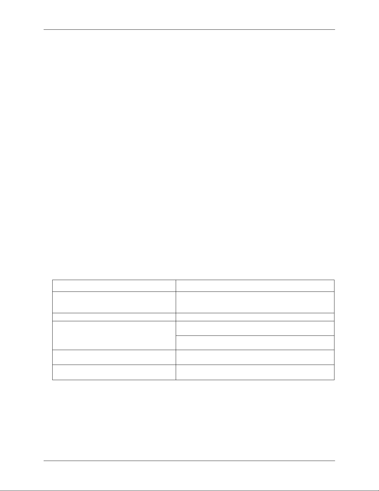
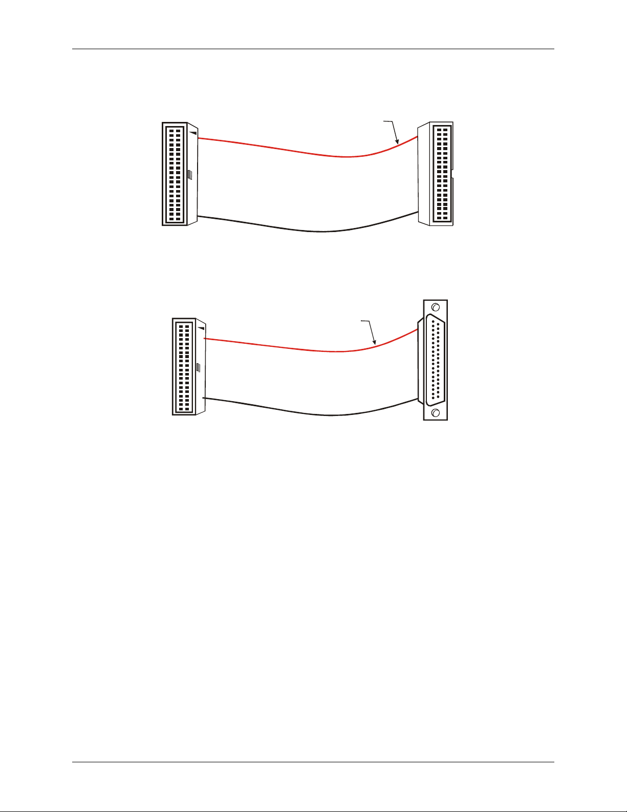
Cabling
For signal connections and termination, you can use the CIO-MINI40 screw terminal board and C40FF-x cable.
Figure 2. C40FF-x cable
For connections to 37-pin connectors or boards, you can use the C40-37F-x or C40F-37M-x cable.
Figure 3. C40-37F-x cable
Field wiring, signal termination and conditioning
You can use the 40-pin CIO-MINI40 universal screw terminal board to terminate field signals and route them
into the USB-2020 using the C40FF-x cable:
You can use the following MCC screw terminal boards to terminate field signals and route them into the
USB-2020 using the C40-37F-x cable directly:
CIO-MINI37 – 37-pin universal screw terminal board.
SCB-37 – 37-conductor, shielded signal connection/screw terminal box.
10
Page 11

Chapter 3
Functional Det ails
Analog input acquisition m ode s
The USB-2020 can acquire analog input data in three different modes – software paced, continuous scan
(hardware paced), and BURSTIO.
Software paced
In software paced mode, you can acquire one analog sample at a time. You initiate the A/D conversion by
calling a software command. The analog value is converted to digital and returned to the computer. You repeat
this procedure until you have the total number of samples that you want from one channel.
The typical throughput sample rate in software paced mode is 4 kS/s (system-dependent).
Continuous scan (hardware paced)
Continuous scan mode enables data to be directly transferred to the host computer during acquisition. The
maximum rate in continuous scan mode is 8 MS/s for all acquired data (one channel or two channels). The
maximum rate achieved depends on the host computer..
BURSTIO
When using BURSTIO, the USB-2020 can acquire data at the maximum rate of 20 MS/s per channel to the
internal memory buffer (up to 64 megasamples)
user buffer in the computer. You can initiate a single acquisition sequence of one to two channels with either a
software command or an external hardware trigger event.
When BURSTIO is enabled, scans are limited to the depth of the onboard memory, as the data is acquired at a
rate faster than it can be transferred to the computer. Time must be allowed between scans for the acquisition
and the transfer of the data.
1
. The acquired data is read from the FIFO and transferred to a
1
In some situations, the available memory is restricted below 64 megasamples. Refer to Buffer
size limitations on Windows systems on page 15 for more information.
11
Page 12
USB-2020 User's Guide Functional Details
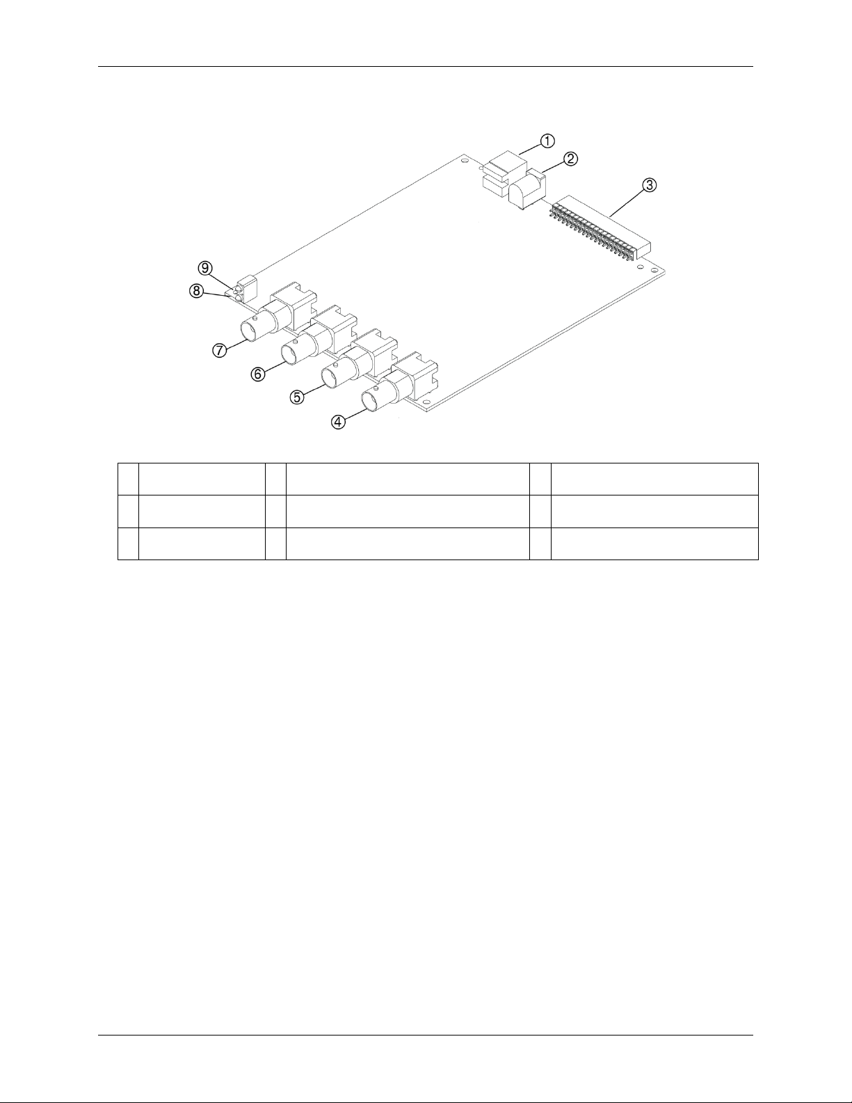
1
USB connector
4
Clock I/O BNC connector (CLK IO)
7
Analog input channel 0 BNC
connector (CH0)
2
External power connector
5
External digital trigger input BNC connector
(TRIG IN)
8
USB Activity LED
3
40-pin IDC connector
6
Analog input channel 1 BNC connector
CH1
9
Device Ready LED
Connectors and LEDs
Figure 4. Location of connectors and LEDs
(
)
BNC connectors
The USB-2020 has four BNC connectors that provide connections for the following signals:
Two single-ended analog inputs
One external digital trigger input
One clock input/output
The external digital trigger input signal is also available on the 40-pin IDC connector.
Status LEDs
The Device Ready LED turns on after the device is enumerated by the system and is associated with a
hardware driver.
USB Activity LED turns on when the USB-2020 is transmitting or receiving data.
The
USB connector
The USB connector provides power to the USB-2020 and communication with the host computer.
External power connecto r
The USB-2020 requires external power. Connect the CB-PWR-9 power supply to the external power connector.
This power supply provides 9 VDC, 3 A power, and plugs into a standard 120 VAC outlet.
12
Page 13

USB-2020 User's Guide Functional Details
Pin Description
Signal Name
Pin
Pin
Signal Name
Pin Description
Ground
GND 1 • • 2
+VO
Power output
Ground
GND 3 • • 4
N/C
Do not connect
Digital I/O bit 7
DIO7
5 • • 6 N/C
Do not connect
Digital I/O bit 6
DIO6
7 • • 8 N/C
Do not connect
Digital I/O bit 5
DIO5
9 • •
10
TRIG IN
External digital trigger input
Digital I/O bit 4
DIO4
11 • •
12
GND
Ground
Digital I/O bit 3
DIO3
13 • •
14
GND
Ground
Digital I/O bit 2
DIO2
15 • •
16
GND
Ground
Digital I/O bit 0
DIO0
19 • •
20
GND
Ground
Ground
GND
21 • •
22
N/C
Do not connect
Do not connect
N/C
23 • •
24
N/C
Do not connect
Ground
GND
25 • •
26
N/C
Do not connect
Do not connect
N/C
27 • •
28
N/C
Do not connect
Ground
GND
29 • •
30
N/C
Do not connect
Do not connect
N/C
31 • •
32
N/C
Do not connect
Ground
GND
33 • •
34
N/C
Do not connect
Power output
+VO
35 • •
36
N/C
Do not connect
Do not connect
N/C
39 • •
40
N/C
Do not connect
40-pin auxiliary connector (J9)
The 40-pin auxiliary connector provides the following connections for all I/O signals except for analog input
and clock I/O:
Eight digital I/O (
Digital trigger input (
12 ground connections (
Two +5V power outputs (
DIO0 to DIO7)
TRIG IN)
GND)
+VO)
The signals that are available on the 40-pin IDC connector are listed below. Connect signals on the 40-pin IDC
connector using a C40FF-x cable or C40-37F-x cable.
40-pin IDC connector pin out
Digital I/O bit 1 DIO1 17 • • 18 GND Ground
Ground GND 37 • • 38 N/C Do not connect
13
Page 14

USB-2020 User's Guide Functional Details
Pin
Signal Name
Pin
Signal Name
1
GND 1 GND
2
+VO
20
+VO 3 GND 2 GND 4 N/C
21
N/C 5 DIO7
3
DIO7
6
N/C
22
N/C 7 DIO6
4
DIO6
8
N/C
23
N/C 9 DIO5
5
DIO5
10
TRIG IN
24
TRIG IN
11
DIO4
6
DIO4
12
GND
25
GND
13
DIO3
7
DIO3
14
GND
26
GND
15
DIO2
8
DIO2
16
GND
27
GND
17
DIO1
9
DIO1
18
GND
28
GND
19
DIO0
10
DIO0
20
GND
29
GND
21
GND
11
GND
22
N/C
30
N/C
23
N/C
12
N/C
24
N/C
31
N/C
25
GND
13
GND
26
N/C
32
N/C
27
N/C
14
N/C
28
N/C
33
N/C
29
GND
15
GND
30
N/C
34
N/C
31
N/C
16
N/C
32
N/C
35
N/C
33
GND
17
GND
34
N/C
36
N/C
35
+VO
18
+VO
36
N/C
37
N/C
37
GND
19
GND
38
N/C
39
N/C
40
N/C
40-pin to 37-pin signal mapping
Signal mapping on the C40-37F-x cable is not a one-to-one ratio. The following table lists the pin numbers of
the signals on the 40-pin end and the pin numbers of the associated signals on the 37-pin end.
Signal mapping on the C40-37F-x cable
40-pin cable end 37-pin cable end
Signal connections
Analog input
The USB-2020 has two single-ended simultaneous sampling analog inputs that provide sampling at rates of up
to 20 MS/s to internal memory when using BURSTIO and at rates of up to 8 MS/s (system-dependent) to the
host computer in continuous scan mode. The input ranges are software-selectable for ±10 V, ±5 V, ±2 V, ±1 V.
When using BURSTIO, the internal memory can store up to 64 megasamples at the maximum rate for transfer
to the computer after the acquisition is complete. Data is transferred to the host computer at a maximum rate of
8 MS/s (system-dependent).
14
Page 15

USB-2020 User's Guide Functional Details
Buffer size limitations on Windows systems
When creating very large buffers in Windows, you may receive the message The requested amount of
Windows page-locked memory is not available when you try to start a scan. This error occurs when there is
enough memory to create the buffer, but the memory cannot be locked down. For example, the driver can only
lock a maximum buffer size of 67,107,800 bytes (33,553,900 samples) on Windows XP systems. A workaround
for this is available when BURSTIO is enabled, allowing you to transfer the entire 64 MS of data from the
onboard memory to the Windows buffer. For more information, refer to the USB-2020 topic (Hardware
Considerations section) in the Universal Librar y Help (User's Guide section).
You can pace analog input operations with the internal A/D clock or with an external clock source. When using
an external input scan clock, connect the clock source to the
CLK IO BNC connector.
External clock I/O
USB-2020 analog input scanning operations can be paced with the internal A/D clock or with an external clock
source.
The CLK IO connector can be configured through software for input (default) for external pacing, or for output
to pace a connected device.
Digital I/O
You can connect up to eight digital I/O lines to DIO0 through DIO7 on the 40-pin IDC connector. When a bit is
configured for input, it can detect the state of any TTL-level input.
Digital input voltage ranges of up to 0 to 15 V are permitted, with thresholds of 0.8 V (low) and 2.0 V (high).
Each DIO channel is an open-drain, which can sink up to 150 mA for direct drive applications when used as an
output.
Figure 6 shows an example of a typical digital output connection.
Figure 5. Digital output connection
External pull-up capability
Inputs are pulled high by default to 5 V through 47 kΩ resistors on the circuit board. The pull-up voltage is
common to all 47 kΩ resistors.
You can configure the pull-up/pull-down state by changing the placement of the shorting block located at the
three-pin header J10. Pull-up is the default factory configuration
15
Page 16

USB-2020 User's Guide Functional Details
Pull
(factory default)
-up default configuration
Pull-down configuration
Figure 6. Pull-up and pull-down jumper configurations (J10)
An external pull-up resistor can be used to pull the DIO bit up to a voltage that exceeds the internal 5 V pull-up
voltage (15 V maximum). Be aware that this would place the 47k internal pull up resistor in a parallel
resistance configuration that could offset the logic high voltage level.
Figure 7. Digital I/O external resistor configuration
Trigger input
Both the TRIG IN BNC connector and the TRIG IN IDC pin are external digital trigger/gate inputs that you can
configure through software.
An analog scan can have a trigger or a gate, but not both. For example, you cannot use an analog trigger and use
TRIG IN BNC connector to gate at the same time.
the
A trigger or gate can be digital or analog.
Digital triggers can be configured for rising or falling edge, or for high or low level.
Analog triggers can be configured for software-selectable high or low level, or for rising or falling edge
with software-selectable hysteresis.
Digital gates can be configured for high or low level.
Analog gates can be configured for software-selectable high or low level, or for in or out of software-
selectable window.
16
Page 17

USB-2020 User's Guide Functional Details
Each configuration is explained below:
High or low level − Trigger or gate an acquisition when an input signal is higher or lower than the specified
voltage.
Rising or falling edge − Trigger an acquisition when input signals cross a specified voltage (rising or
falling)
Window − Gate an acquisition when the input signal is within or outside two specified voltages (in/out of
window)
Hysteresis − After the input signal has passed through one specified voltage, trigger an acquisition when
the input signal passes through a second voltage (positive or negative). For example, once the signal goes
below 5 V, a rising edge that crosses 4 V must occur to trigger an acquisition.
Mechanical drawing
Figure 8. USB-2020 board dimensions
17
Page 18

A/D converter type
AD9225
Number of channels
2 Resolution
12-bits
Sampling method
Simultaneous
Input ranges
±10 V, ±5 V, ±2 V, ±1 V, software-selectable
Connection type
BNC
Input coupling
DC
Absolute maximum input
voltage
±15 V max (power on)
Input impedance
1.5 MΩ typ
Input leakage current
2 uA typ, 10 uA max
Input bandwidth (3 db)
All input ranges
17 MHz typ
Trigger source
Digital
TRIG IN (BNC connector and 40-pin connector)
See External trigger for more information
Analog
CH0 or CH1
Sample clock source
Internal
1 kHz to 20 MHz max
External
CLK IO (BNC connector)
See External clock input/output for more information
Throughput
Software paced
33 S/s to 4 kS/s typ; system-dependent
BURSTIO
1 kS/s to 20 MS/s to 64 MS onboard memory
Data transfer rate
From onboard memory
10 MS/s typ
Signal-to-noise ratio(SNR)
66.6 dB
Signal-to-noise and distortion
ratio (SINAD)
66.5 dB
Spurious free dynamic range
(SFDR)
80 dB
Total harmonic distortion
(THD)
80 dB
Specifications
All specifications are subject to change without notice.
Typical at 25 °C unless otherwise specified
Specifications in italic text are guaranteed by design.
Analog input
Table 1. Analog input specifications
Parameter Condition Specification
Input configuration Single-ended, individual A/D per channel
Chapter 4
Crosstalk DC to 10 kHz –90 dB
Continuous scan 1 kS/s to 8 MS/s, system-dependent
18
Page 19
USB-2020 User's Guide Specifications
±10 V
0.11
5.2
0.0976
35.72
0.0035
30
±5 V
0.11
5.2
0.0488
20.46
0.0035
110
±2 V
0.11
1.1
0.0244
8.18
0.0035
10
±1 V
0.11
1.1
0.0122
4.64
0.0035
25
±10 V
5
0.76
±5 V
5
0.76
±2 V
7
1.06
±1 V
7
1.06
Recommended warm-up time
15 minutes min.
Calibration method
Self calibration, with calibration factors for each range stored onboard in non-volatile
memory
Calibration interval
1 year (factory calibration)
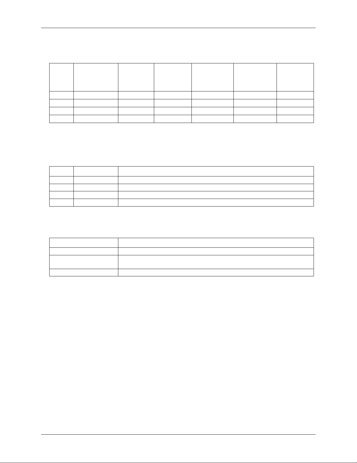
Accuracy
Table 2. DC Accuracy components and specifications. All values are (±)
Range Gain error
(% of reading)
Offset error
(mV)
INL error
(% of range)
Absolute
accuracy at
Full Scale
(mV)
Gain
temperature
coefficient
(% reading/°C)
Offset
temperature
coefficient
(µV/°C)
Noise performance
For the peak-to-peak noise distribution test, a single-ended input channel is connected to AGND at the input
BNC connector and 20,000 data samples are acquired at the maximum rate.
Table 3. Noise performance specifications
Range Counts LSBrms
Analog input calibration
Table 4. Analog input calibration specifications
Parameter Specification
19
Page 20

USB-2020 User's Guide Specifications
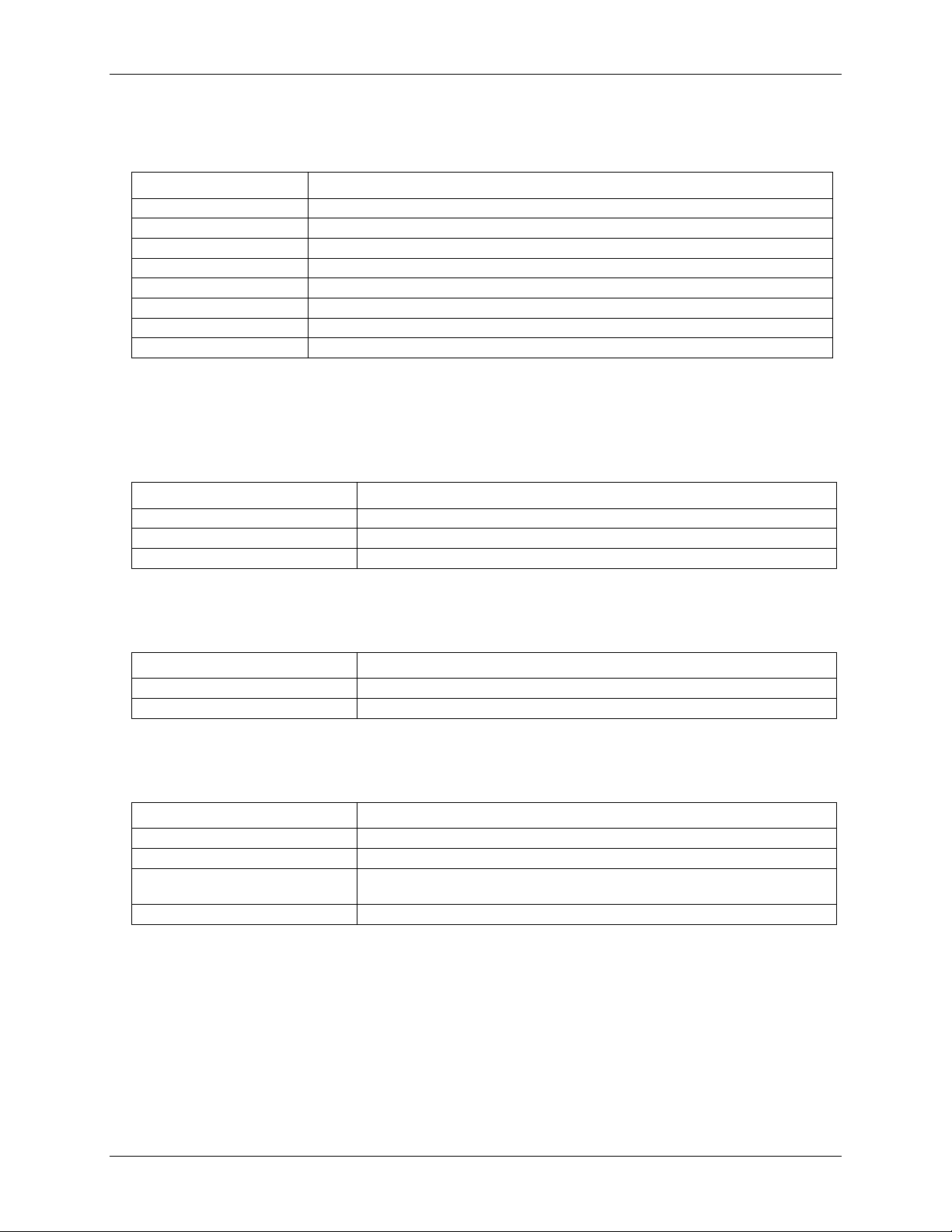
Digital type
CMOS
Number of I/O
8
Configuration
Each bit can be independently configured as input (power on default) or
stated.
Input voltage range
0 V to 15 V
Input characteristics
47 kΩ pull-up/pull-down resistor, 28 kΩ series resistor
Abs. Maximum input voltage
+20 V max
Pull-up/pull-down configuration
The port has 47 kΩ resistors that can be configured as pull-up or pull-down
pins 2 and 3.
Digital I/O transfer rate (software paced)
33 S/s to 4,000 S/s typ; system-dependent
Input high voltage
2.0 V min
Input low voltage
0.8 V max
Output characteristics
47 kΩ pull-up, open drain (DMOS transistor, source connected to ground)
Output voltage range
0 V to 5 V (using 47 KΩ internal pull up resistors)
(Note 1)
Drain to source breakdown voltage
42.5 V min (Note 2)
Sink current capability
150 mA max (continuous) per output pin
150 mA max (continuous), total for all eight channels
DMOS transistor on-resistance (drain to
source)
4 Ω
Digital input/output
Table 5. Digital I/O specifications
Parameter Specification
output
Input bits can be read at any time whether the digital output is active or tri-
with an internal jumper. The factory configuration is pull-up (J10 shorting
block default position is pins 1 and 2)
Pull down capability is available by placing the J10 shorting block across
0 V to 15 V max through optional, user-supplied external pull-up resistors
Off state leakage current 1.0 µA
Note 1: Adding external pull-up resistors connects the output bit in parallel with the internal 47 kΩ pull-up
resistor. The resulting load voltage depends on the value of the external resistor value and the pull-up
voltage used. In general, external 10 KΩ pull-up resistors are sufficient for most applications.
Note 2: Does not include the additional leakage current contribution that can occur when using an external
pull-up resistor.
20
Page 21

USB-2020 User's Guide Specifications
Trigger source
Digital
TRIG IN (BNC connector and 40-pin connector)
Analog
CH0 or CH1
Trigger mode
Digital
Rising or falling edge, high or low level
Analog
Trigger above or below software-selectable level, rising or
falling edge with software-selectable hysteresis
A/D gate source
Digital
TRIG IN (BNC connector and 40-pin connector)
Analog
CH0 or CH1
A/D gate modes
Digital
High or low level
Analog
Software-selectable high or low level, in or out of softwareselectable window
Trigger latency
50 ns max
Trigger pulse width
25 ns min
Input type
49.9 Ω series resistor
Input high voltage
2.0 V min
Input low voltage
0.8 V max
Terminal name
CLK IO (BNC connector)
Terminal type
ADC clock input/output, software-selectable for input or output (default is input)
When configured for output, outputs the internal sampling clock
Clock rate
1 kHz to 20 MHz max
Stability
±50 ppm
Input impedance
1 MΩ
Input threshold
High: 2.0 V min
Low: 0.8 V max
Maximum rate
20 MHz
Input range
0 V to 5.5 V
Clock pulse width
25 ns min
Input type
49.9 Ω series resistor
Input high voltage
2.0 V min
Input low voltage
0.8 V max
Output low voltage
0.4 V max
Output current
24 mA max
Data FIFO
64 MS using BURSTIO, 4 kS not using BURSTIO
Non-volatile memory
32 KB (30 KB firmware storage, 2 KB calibration/user data)
External trigger
Table 6. External trigger specifications
Parameter Condition Specification
External clock input/output
Table 7. External clo ck I/ O spe ci fications
Parameter Specification
Terminal description When configured for input, receives sampling clock from external source
Output high voltage 2.4 V min
Memory
Table 8. Memory specifications
Parameter Specification
21
Page 22
USB-2020 User's Guide Specifications
Supply voltage
9 VDC to 18 VDC ( MCC plug-in power supply CB-PWR-9 recommended)
Supply current
0.75 A max (Note 3)
Power jack configuration
Two conductor, barrel
Power jack barrel diameter
6.3 mm
Power jack pin diameter
2.0 mm
+VO voltage range
4.50 V to 5.25 V
+VO current sourcing
10 mA max.
Operating temperature range
0 °C to 50 °C max
Storage temperature range
–40 °C to 85 °C max
Humidity
0% to 90% non-condensing max
Dimensions (L × W × H)
142.24 × 180.34× 38.09 mm (5.6 × 7.1 × 1.5 in.)
Weight
1.5 lb
USB device type
USB 2.0 (high-speed)
Device compatibility
USB 2.0
min 28 AWG D+/D–)
USB cable length
3 m (9.84 ft) max
Power
Table 9. Power specifications
Parameter Specification
Power jack polarity Center positive
Note 3: This is the total quiescent current requirement for the device that includes up to 10 mA for the Status
LED. This value does not include potential loading of the DIO bits or the +VO pin.
Environmental
Table 10. Environmental speci ficat ion s
Parameter Specification
Mechanical
Table 11. Mechanical specific ation s
Parameter Specification
USB
Table 12. USB specifications
Parameter Specification
USB cable type
A-B cable, UL type AWM 2527 or equivalent. (min 24 AWG VBUS/GND,
22
Page 23

USB-2020 User's Guide Specifications
USB
B type
Auxiliary connector (J9)
40-pin header connector
Compatible cables for the 40-pin
C40FF-x
Compatible accessory products with
CIO-MINI40
Compatible accessory products with
CIO-MINI37
SCB-37
CH0
Analog input channel 0
CH1
Analog input channel 1
TRIG IN
BNC connection for external digital trigger (Note 4)
BNC connection for the ADC clock input/output, software-selectable for input or
output (default is input)
Pin
Signal name
Pin description
Pin
Signal name
Pin description
1
GND
Ground
2
+VO
Power output
3
GND
Ground
4
N/C
Do not connect
5
DIO7
Digital I/O bit 7
6
N/C
Do not connect
7
DIO6
Digital I/O bit 6
8
N/C
Do not connect
9
DIO5
Digital I/O bit 5
10
TRIG IN
External digital trigger input
11
DIO4
Digital I/O bit 4
12
GND
Ground
15
DIO2
Digital I/O bit 2
16
GND
Ground
17
DIO1
Digital I/O bit 1
18
GND
Ground
19
DIO0
Digital I/O bit 0
20
GND
Ground
21
GND
Ground
22
N/C
Do not connect
23
N/C
Do not connect
24
N/C
Do not connect
25
GND
Ground
26
N/C
Do not connect
29
GND
Ground
30
N/C
Do not connect
33
GND
Ground
34
N/C
Do not connect
35
+VO
Power output
36
N/C
Do not connect
37
GND
Ground
38
N/C
Do not connect
39
N/C
Do not connect
40
N/C
Do not connect
Signal I/O connectors
Table 13. Connector specifications
Connector Specification
auxiliary connector
the C40FF-x cable
the C40-37F-x cable
BNC connectors
BNC signal name Signal description
C40-37F-x
Table 14. BNC connector pinout
CLK IO
Note 4: Also available on the auxiliary connector J9.
Auxiliary connector
Table 15. 40-pin connector J9 pinout
13 DIO3 Digital I/O bit 3 14 GND Ground
27 N/C Do not connect 28 N/C Do not connect
31 N/C Do not connect 32 N/C Do not connect
Note 5: N/C = no connection, not used
23
Page 24

Measurement Computing Corporation
10 Commerce Way
Suite 1008
Norton, Massachusetts 02766
(508) 946-5100
Fax: (508) 946-9500
E-mail:
info@mccdaq.com
www.mccdaq.com
 Loading...