

Page 1

USB-1608GX-2AO
Document Revision 1
November 2014
© Copyright 2014
User's Guide
Multifunction DAQ Device
Page 2

HM USB-1608GX-2AO.docx
Your new Measurement Computing product comes with a fantastic extra —
Management committed to your satisfaction!
Thank you for choosing a Measurement Computing product—and congratulations! You own the finest, and you can now enjoy
the protection of the most comprehensive warranties and unmatched phone tech support. It’s the embodiment of our mission:
To provide data acquisition hardware and software that will save time and save money.
Simple installations minimize the time between setting up your system and actually making measurements. We offer quick and
simple access to outstanding live FREE technical support to help integrate MCC products into a DAQ system.
Limited Lifetime Warranty: Most MCC products are covered by a limited lifetime warranty against defects in materials or
workmanship for the life of the product, to the original purchaser, unless otherwise noted. Any products found to be defective in
material or workmanship will be repaired, replaced with same or similar device, or refunded at MCC’s discretion. For specific
information, please refer to the terms and conditions of sale.
Harsh Environment Program: Any Measurement Computing product that is damaged due to misuse, or any reason, may be
eligible for replacement with the same or similar device for 50% of the current list price. I/O boards face some harsh
environments, some harsher than the boards are designed to withstand. Contact MCC to determine your product’s eligibility for
this program.
30 Day Money-Back Guarantee: Any Measurement Computing Corporation product may be returned within 30 days of
purchase for a full refund of the price paid for the product being returned. If you are not satisfied, or chose the wrong product by
mistake, you do not have to keep it.
These warranties are in lieu of all other warranties, expressed or implied, including any implied warranty of merchantability or
fitness for a particular application. The remedies provided herein are the buyer’s sole and exclusive remedies. Neither
Measurement Computing Corporation, nor its employees shall be liable for any direct or indirect, special, incidental or
consequential damage arising from the use of its products, even if Measurement Computing Corporation has been notified in
advance of the possibility of such damages.
Trademark and Copyright Information
Measurement Computing Corporation, InstaCal, Universal Library, and the Measurement Computing logo are either trademarks
or registered trademarks of Measurement Computing Corporation. Refer to the Copyrights & Trademarks section on
mccdaq.com/legal for more information about Measurement Computing trademarks. Other product and company names
mentioned herein are trademarks or trade names of their respective companies.
© 2014 Measurement Computing Corporation. All rights reserved. No part of this publication may be reproduced, stored in a
retrieval system, or transmitted, in any form by any means, electronic, mechanical, by photocopying, recording, or otherwise
without the prior written permission of Measurement Computing Corporation.
Notice
Measurement Computing Corporation does not authorize any Measurement Computing Corporation product for use
in life support systems and/or devices without prior written consent from Measurement Computing Corporation.
Life support devices/systems are devices or systems that, a) are intended for surgical implantation into the body, or
b) support or sustain life and whose failure to perform can be reasonably expected to result in injury. Measurement
Computing Corporation products are not designed with the components required, and are not subject to the testing
required to ensure a level of reliability suitable for the treatment and diagnosis of people.
Page 3

Table of Contents
Preface
About this User's Guide ....................................................................................................................... 5
What you will learn from this user's guide ......................................................................................................... 5
Conventions in this user's guide ......................................................................................................................... 5
Where to find more information ......................................................................................................................... 5
Chapter 1
Introducing the USB-1608GX-2AO ...................................................................................................... 6
Functional block diagram ................................................................................................................................... 6
Chapter 2
Installing the USB-1608GX-2AO .......................................................................................................... 7
Unpacking........................................................................................................................................................... 7
Installing the software ........................................................................................................................................ 7
Installing the hardware ....................................................................................................................................... 7
Calibrating .......................................................................................................................................................... 7
Self-calibration ................................................................................................................................................................. 7
Factory calibration ............................................................................................................................................................ 7
Firmware updates ............................................................................................................................................... 7
Chapter 3
Functional Details ................................................................................................................................. 8
Analog input modes ............................................................................................................................................ 8
Software paced .................................................................................................................................................................. 8
Hardware paced ................................................................................................................................................................ 8
Burst mode.......................................................................................................................................................... 8
External components .......................................................................................................................................... 9
USB connector .................................................................................................................................................................. 9
LEDs ................................................................................................................................................................................. 9
Screw terminals................................................................................................................................................................. 9
Signal connections ............................................................................................................................................ 11
Analog input ....................................................................................................................................................................11
Analog output ..................................................................................................................................................................12
External clock I/O ............................................................................................................................................................12
Digital I/O ........................................................................................................................................................................12
Trigger input ....................................................................................................................................................................13
Counter input ...................................................................................................................................................................14
Timer output ....................................................................................................................................................................14
Power output ....................................................................................................................................................................14
Ground ................................................................................................................................................................ .............14
Mechanical drawings ................................................................................................................................ ........ 15
Chapter 4
Specifications ...................................................................................................................................... 16
Analog input ..................................................................................................................................................... 16
Accuracy ........................................................................................................................................................... 17
Analog input DC voltage measurement accuracy ............................................................................................................17
Noise performance ...........................................................................................................................................................17
Settling time .....................................................................................................................................................................17
Analog output ................................................................................................................................................... 18
Analog input/output calibration ........................................................................................................................ 19
Digital input/output........................................................................................................................................... 19
External trigger ................................................................................................................................ ................. 19
External clock input/output............................................................................................................................... 20
3
Page 4

USB-1608GX-2AO User's Guide
Counter ............................................................................................................................................................. 20
Timer ................................................................................................................................................................ 21
Memory ............................................................................................................................................................ 21
Power ................................................................................................................................................................ 21
USB .................................................................................................................................................................. 21
Environmental .................................................................................................................................................. 22
Mechanical ....................................................................................................................................................... 22
Screw terminal connector ................................................................................................................................. 22
Differential mode pinout ..................................................................................................................................................22
Single-ended mode pinout ...............................................................................................................................................23
Declaration of Conformity .................................................................................................................. 24
4
Page 5

About this User's Guide
What you will learn from this user's guide
This user's guide describes the Measurement Computing USB-1608GX-2AO data acquisition device and lists
device specifications.
Conventions in this user's guide
For more information
Text presented in a box signifies additional information and helpful hints related to the subject matter you are
reading.
Caution! Shaded caution statements present information to help you avoid injuring yourself and others,
damaging your hardware, or losing your data.
bold text Bold text is used for the names of objects on a screen, such as buttons, text boxes, and check boxes.
italic text Italic text is used for the names of manuals and help topic titles, and to emphasize a word or phrase.
Preface
Where to find more information
Additional information about the USB-1608GX-2AO is available on our website at www.mccdaq.com. You can
also contact Measurement Computing Corporation by phone, fax, or email with specific questions.
Knowledgebase: kb.mccdaq.com
Tech support form: www.mccdaq.com/support/support_form.aspx
Email: techsupport@mccdaq.com
Phone: 508-946-5100 and follow the instructions for reaching Tech Support
For international customers, contact your local distributor. Refer to the International Distributors section on our
website at www.mccdaq.com/International.
5
Page 6
Chapter 1
Introducing the USB-1608GX-2AO
The USB-1608G is a USB 2.0 high-speed device that provides the following features:
16 single-ended (SE) or eight differential (DIFF) analog input channels
Two analog output channels
Eight individually configurable digital I/O channels
Two counter channels (32-bit) that count TTL pulses
One timer output channel (32-bit)
Screw terminals for field wiring connections
The USB-1608GX-2AO is powered by the +5 volt USB supply from your computer; no external power is
required. A USB cable is shipped with the device.
The USB-1608GX-2AO device is compatible with both USB 1.1 and USB 2.0 ports. The speed of the device
may be limited when using a USB 1.1 port due to the difference in transfer rates on the USB 1.1 versions of the
protocol (low-speed and full-speed).
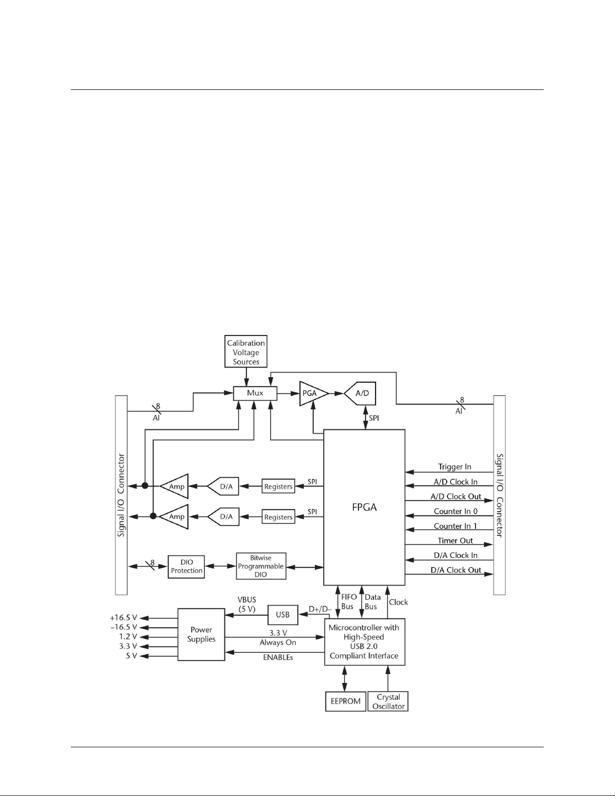
Functional block diagram
USB-1608GX-2AO functions are illustrated in the block diagram shown here.
Figure 1. Functional block diagram
6
Page 7

Chapter 2
Installing the USB-1608GX-2AO
Unpacking
As with any electronic device, you should take care while handling to avoid damage from static
electricity. Before removing the device from its packaging, ground yourself using a wrist strap or by simply
touching the computer chassis or other grounded object to eliminate any stored static charge.
Contact us immediately if any components are missing or damaged.
Installing the software
Refer to the MCC DAQ Quick Start for instructions on installing the software on the MCC DAQ CD. Refer to
the device product page on the Measurement Computing website for information about the included and
optional software supported by the USB-1608GX-2AO.
Install the software before you install your device
The driver needed to run the USB-1608GX-2AO is installed with the software. Therefore, you need to install
the software package you plan to use before you install the hardware.
Installing the hardware
To connect a USB-1608GX-2AO to your system, turn on your computer and connect the USB cable to an
available USB port on the computer or to an external USB hub connected to the computer. Connect the other
end of the USB cable to the USB connector on the device. No external power is required.
When you connect the device for the first time, a Found New Hardware dialog opens when the operating
system detects the device. The dialog closes after the device is installed.
A green Status LED indicates the device status. When the LED is on, the device is powered and ready for
operation. When the LED is off, the device is not powered or did not initialize. Figure 3 on page 9 shows the
location of the Status LED. If the Status LED is on but then turns off, the computer has lost communication
with the device. To restore communication, disconnect the USB cable from the computer and then reconnect it.
This should restore communication, and the LED should turn on.
Caution! Do not disconnect any device from the USB bus while the computer is communicating with
the USB-1608GX-2AO, or you may lose data and/or your ability to communicate with the device.
Calibrating
Self-calibration
The USB-1608GX-2AO supports self-calibration with InstaCal. Calibrate the device whenever the ambient
temperature changes by more than ±10 °C from the last self-calibration.
Factory calibration
The Measurement Computing Manufacturing Test department performs the initial factory calibration. Contact
Measurement Computing for details about how to return your device and have it calibrated to the factory
specifications.
Firmware updates
Your DAQ device contains firmware that can be updated in the field if required. Firmware is available for
download at www.mccdaq.com/firmware.aspx.We recommend that you check this page periodically to see if an
update to your device firmware is available.
7
Page 8
Chapter 3
Functional Details
Analog input modes
The USB-1608GX-2AO device can acquire analog input data in two basic modes – software paced and
hardware paced.
Software paced
You can acquire one analog sample at a time in software paced mode. You initiate the A/D conversion with a
software command. The analog value is converted to digital data and returned to the computer. Repeat this
procedure until you have the total number of samples that you want.
The sample rate in software paced mode is system-dependent and can range from 33 S/s to 4000 S/s.
Hardware paced
You can acquire data from up to 16 channels in hardware paced mode. The analog data is continuously
acquired, converted to digital values, and written into the FIFO buffer on the device until you stop the scan. The
FIFO buffer is serviced in blocks as the data is transferred from the FIFO buffer to the computer memory
buffer. You start a continuous scan with either a software command or with an external hardware trigger event.
The maximum sampling rate in hardware paced mode from one to 16 channels is 500 kS/s aggregate.
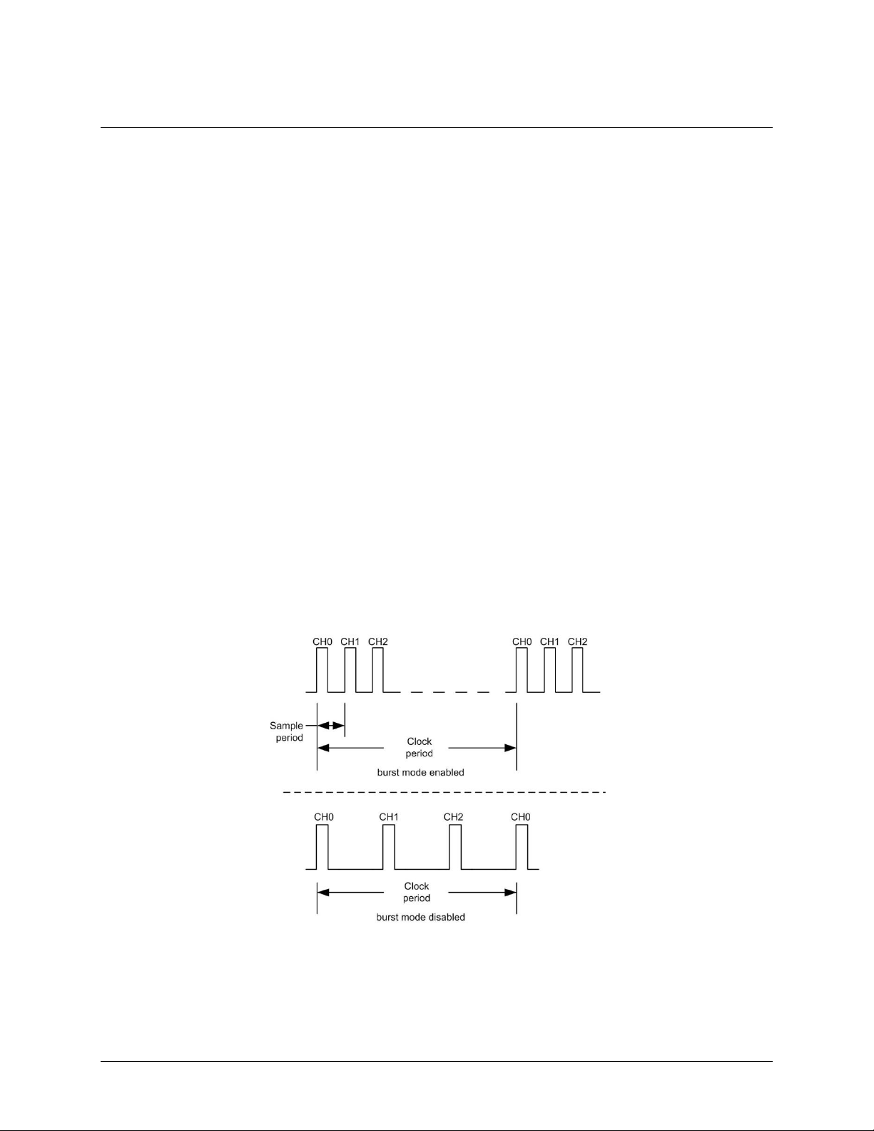
Burst mode
When using the onboard pacer, you can enable burst mode for more precise timing between samples. When
burst mode is enabled, each successive channel in a scan is sampled at the maximum A/D rate. This ensures that
samples from each channel are taken as close as possible to the same absolute point in time. When burst mode
is disabled, data is sampled at evenly spaced intervals, allowing maximum settling time and best amplitude
accuracy. Multi-channel scanning with burst mode enabled and disabled is shown in Figure 2.
Figure 2. Multi-channel scan with burst mode enabled and disabled
The burst mode sample period is 2 µs.
You can trigger the acquisition with the external trigger, and control the clock period with the internal or
external A/D pacer clock. Pacing from the external clock always operates with burst mode enabled.
8
Page 9

USB-1608GX-2AO User's Guide Functional Details
1
Screw terminal pins 1 to 27
4
Activity LED
2
Screw terminal pins 28 to 54
5
USB connector
3
Status LED
External components
The USB-1608GX-2AO has the following external components (see Figure 3):
USB connector
LEDs
Screw terminals
Figure 3. External components
USB connector
The USB connector provides +5 V power and communication. No external power supply is required.
LEDs
The USB-1608GX-2AO has two LEDs – Status and Activity.
The Status LED turns on when the device is detected and installed on the computer.
The Activity LED blinks when data is transferred, and is off otherwise.
Figure 3 shows the location of each LED.
Screw terminals
The screw terminals provide the following connections:
16 SE (CH0 to CH15) or eight DIFF (CH0H/CH0L to CH7H/CH7L) analog inputs
Eight digital I/O bits (DIO0 to DIO7)
Two analog outputs (AOUT0, AOUT1)
One external clock input (AICKI) and one external clock output (AICKO) for analog inputs
One external clock input (AOCKI) and one external clock output (AOCKO) for analog outputs
One digital trigger input (TRIG)
Two counter inputs (CTR0, CTR1)
One timer output (TMR)
One power output (+5V)
Analog ground (AGND) and digital ground (GND) connections
The single-ended mode pinout is shown in Figure 4, and the differential mode pinout is shown in Figure 5.
9
Page 10

USB-1608GX-2AO User's Guide Functional Details
Figure 4. SE mode pinout
Figure 5. DIFF mode pinout
10
Page 11

USB-1608GX-2AO User's Guide Functional Details
Signal connections
Analog input
You can configure the analog inputs for SE or DIFF mode. The input voltage range is software selectable for
±10 V, ±5 V, ±2 V, or ±1 V.
With SE mode, connect up to 16 inputs to screw terminals CH0 to CH15. SE mode requires two wires:
Connect one wire to the signal you want to measure (CHx).
Connect one wire to the analog ground reference (AGND).
Refer to Figure 4 on page 10 for the location of the SE inputs.
With DIFF mode, connect up to eight differential inputs to screw terminals CH0H/CH0L to CH7H/CH7L.
DIFF mode requires two wires plus a ground reference:
Connect one wire to the high/positive signal (CHxH).
Connect one wire to the low/negative signal (CHxL).
Connect one wire to the analog ground reference (AGND).
Refer to Figure 5 on page 10 for the location of the DIFF inputs.
Floating voltage source
When connecting DIFF voltage inputs to a "floating" voltage source, make sure the DIFF input channel has a
DC return path to ground. To create this path, connect a resistor from each low channel input to an AGND pin.
A value of approximately 100 kΩ can be used for most applications.
Leave unused input channels either floating or tied to an AGND terminal. Source impedances should be kept as
small as possible to avoid settling time and accuracy errors.
Figure 6 shows DIFF channels 0-3 connected to a ground path resistor.
Figure 6. DIFF connections with ground path resistor
Channel-Gain queue
The USB-1608GX-2AO channel-gain queue feature allows you to configure a list of channels, modes, and
gains for each scan. The settings are stored in a channel-gain queue list that is written to local memory on the
device.
The channel-gain queue list contains one or more channel numbers, modes, and range settings. You can
configure up to 16 elements. The channels can be listed in any order, and can include duplicate channels for
sampling at different ranges.
11
Page 12
USB-1608GX-2AO User's Guide Functional Details
Element
Channel
Range
Mode
0
CH5
BIP5V
SE
1
CH1
BIP10V
DIFF
2
CH15
BIP1V
SE
3
CH5
BIP5V
SE
An example of a 4-element list is shown in the table below.
Sample channel-gain queue list
Carefully match the gain to the expected voltage range on the associated channel or an over range condition
may occur. Although this condition does not damage the device, it does produce a useless full-scale reading,
and can introduce a long recovery time due to saturation of the input channel.
For more information about analog signal connections
For more information about analog input connections, refer to the Guide to DAQ Signal Connections (available
on our web site at www.mccdaq.com/signals/signals.pdf).
Analog output
The two 16-bit analog outputs (AOUT0 and AOUT1) can be updated simultaneously at a rate of 250 kS/s per
channel. One output can be updated at a rate of 500 kS/s. The output range is fixed at ±10 V. The outputs
default to 0 V when the host computer is shut down or suspended, or when a reset command is issued to the
device.
External clock I/O
The device has one external clock input (AICKI) and one external clock output (AICKO) for analog inputs, and
one external clock input (AOCKI) and one external clock output (AOCKO) for analog outputs.
You can connect an external clock signal to AICKI and/or AOCKI.
When using an external clock, AICKO outputs the pulse generated from AICKI, and AOCKO pin outputs the
pulse generated from AOCKI.
When using the internal clock, AICKO outputs the ADC scan clock, and AOCKO outputs the DAC scan
clock.
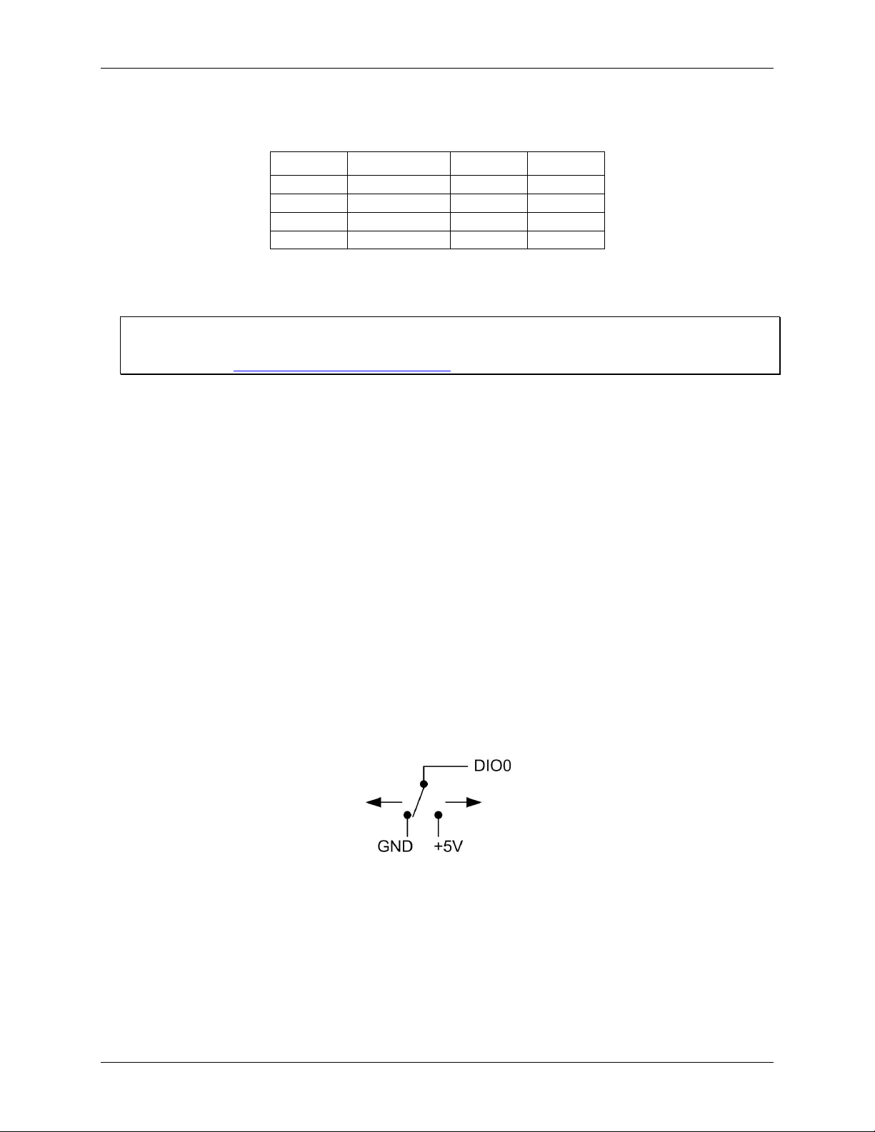
Digital I/O
You can connect up to eight digital I/O lines to DIO0 through DIO7. Each digital channel is individually
configurable for input or output. The digital I/O terminals can detect the state of any TTL-level input. Refer to
the schematic shown in Figure 7.
Figure 7. Schematic showing switch detection by digital channel DIO0
If you set the switch to the +5 V input, DIO0 reads TRUE (1). If you move the switch to GND, DIO0 reads
FALSE (0).
12
Page 13

USB-1608GX-2AO User's Guide Functional Details
Internal pull-up/down configuration
Unconnected inputs are pulled low by default to 0 V through 47 kΩ resistors via jumper W1 on the circuit
board. The pull-up/pull-down voltage is common to all 47 kΩ resistors. Complete the following steps to
configure these inputs to pull high (+5V).
Caution! The discharge of static electricity can damage some electronic components. Before removing the
device from its housing, ground yourself using a wrist strap or touch the computer chassis or other
grounded object to eliminate any stored static charge.
1. Turn the device over and rest the top of the housing on a flat, stable surface.
2. Peel off the four rubber feet on the bottom of the device to access the screws.
3. Remove the four screws from the bottom of the device.
4. Hold both the top and bottom sections together, turn the device over and rest it on the surface, then
carefully remove the top section of the case to expose the circuit board.
5. Configure jumper W1 for either pull-up or pull-down. The jumper is configured by default for pull-down.
Figure 8 shows the location of the jumper on the board.
Figure 8. W1 jumper location
Figure 9 shows the jumper configured for pull-up and pull-down.
Figure 9. W1 jumper configurations
6. Replace the top section of the case, and fasten it to the bottom section with the four screws. Replace the
rubber feet onto each screw.
For more information about digital signal connections
For general information about digital signal connections and digital I/O techniques, refer to the Guide to Signal
Connections (available on our web site at www.mccdaq.com/signals/signals.pdf).
Trigger input
The TRIG terminal is an external digital trigger input. The trigger mode is software selectable for edge or level
sensitive.
Edge sensitive mode is configurable for rising or falling edge.
Level sensitive mode is configurable for high or low level.
The default setting at power up is edge sensitive, rising edge.
Retrigger mode
Retrigger mode lets you set up repetitive analog input or output trigger events. The trigger is automatically rearmed after it is activated. Use software to set the A/D or D/A trigger count (the number of samples you want
per trigger).
13
Page 14

USB-1608GX-2AO User's Guide Functional Details
Counter input
The CTR0 and CTR1 terminals are 32-bit event counters that can accept frequency inputs up to 20 MHz. The
internal counter increments when the TTL levels transition from low to high.
Timer output
The TMR terminal is a pulse width modulation (PWM) timer output that can generate a pulse output with a
programmable frequency in the range of 0.0149 Hz to 32 MHz. The timer output parameters are software
selectable. Figure 10 shows the timer output schematic.
Figure 10. Timer output schematic
Power output
The +5V terminal can output up to 10 mA maximum. You can use this terminal to supply power to external
devices or circuitry.
Caution! The +5V terminal is an output. Do not connect to an external power supply or you may damage the
device and possibly the computer.
Ground
The analog ground (AGND) terminals provide a common ground for all analog channels.
The digital ground (GND) terminals provide a common ground for the digital, counter, timer, and clock
channels and the power terminal.
14
Page 15

USB-1608GX-2AO User's Guide Functional Details
Mechanical drawings
Figure 11. USB-1608GX-2AO circuit board (top) and enclosure dimensions
15
Page 16

Parameter
Condition
Specification
A/D converter type
Successive approximation
ADC resolution
16 bits
Number of channels
8 differential, 16 single-ended
Software-selectable
Input voltage range
±10 V, ±5 V, ±2 V, ±1 V
Software-selectable per channel
Absolute max input voltage
CHx relative to AGND
±25 V max (power on)
±15 V max (power off)
Input impedance
1 GΩ (power on)
820 Ω (power off)
Input bias current
±10 nA
Input bandwidth
All input ranges,
small signal (–3 dB)
870 kHz
Input capacitance
60 pf
Max working voltage (signal
+ common mode)
±10V range
±10.2 V max relative to AGND
±5V range
±10.2 V max relative to AGND
±2V range
±9.5 V max relative to AGND
±1V range
±9.0 V max relative to AGND
Common mode rejection ratio
(fIN = 60 Hz, all input
ranges)
86 dB
Crosstalk
Adjacent differential mode
channels, DC to 100 kHz
–75 dB
Input coupling
DC
Sampling rate
0.0149 Hz to 500 kHz; software-selectable
Trigger source
TRIG (see External trigger on page 19)
Sample clock source
Internal A/D clock or external A/D clock (AICKI pin)
Burst mode
2 µs
Software-selectable using the internal A/D clock; always
enabled when using the external clock (AICKI pin).
Throughput
Software paced
33 to 4000 S/s typ, system dependent
Hardware paced
500 kS/s max
Channel gain queue
Up to 16 elements
Software-selectable range for each channel
Warm-up time
15 minutes min
Specifications
All specifications are subject to change without notice.
Typical for 25 °C unless otherwise specified.
Specifications in italic text are guaranteed by design.
Analog input
Table 1. General analog input specifications
Chapter 4
16
Page 17

USB-1608GX-2AO User's Guide Specifications
Range
Gain error
(% of reading)
Offset error
(µV)
INL error
(% of range)
Absolute
accuracy at
Full Scale
(µV)
Gain
temperature
coefficient
(% reading/°C)
Offset
temperature
coefficient
(µV/°C)
±10 V
0.024
915
0.0076
4075
0.0014
47
±5 V
0.024
686
0.0076
2266
0.0014
24
±2 V
0.024
336
0.0076
968
0.0014
10
±1 V
0.024
245
0.0076
561
0.0014
5
Range
Counts
LSBrms
±10 V
6
0.91
±5 V
6
0.91
±2 V
7
1.06
±1 V
9
1.36
Range
2 µS settling accuracy
(% FSR)
4 µS settling accuracy
(% FSR)
9 µS settling accuracy
(% FSR)
±10 V
0.1251
0.0031
0.0015
±5 V
0.0687
0.0031
0.0015
±2 V
0.0687
0.0031
0.0015
±1 V
0.0687
0.0031
0.0015
Accuracy
Analog input DC voltage measurement accuracy
Table 2. DC accuracy components and specifications. All values are (±)
Noise performance
For the peak-to-peak noise distribution test, a differential input channel is connected to AGND at the input
terminal block, and 32,000 samples are acquired at the maximum rate available at each setting.
Table 3. Noise performance specifications
Settling time
Settling time is defined as the accuracy that can be expected after one conversion when switching from a
channel with a DC input at one extreme of full scale to another channel with a DC input at the other extreme of
full scale. Both input channels are configured for the same input range.
Table 4. Input settling time specifications in µS, typical
17
Page 18

USB-1608GX-2AO User's Guide Specifications
Parameter
Condition
Specification
Number of channels
2 Resolution
16 bits
Output ranges
Calibrated
±10 V
Output transient
Host computer is reset, powered on, suspended,
or a reset command is issued to the device
Duration: 500 µs
Amplitude: 2 V p-p
Powered off
Duration: 10 ms
Amplitude: 7 V peak
Differential
non-linearity
±0.25 LSB typ
±1 LSB max
Output current
AOUTx pins
±3.5 mA max
Output short-circuit
protection
AOUTx connected to AGND
Unlimited duration
Output coupling
DC
Power on and
reset state
DACs cleared to zero-scale: 0 V, ±50 mV
Output noise
30 µVrms
Trigger source
TRIG (see External trigger on page 19)
Sample clock source
Internal D/A clock or external D/A clock
(AOCKI pin)
Output update rate
500 kHz / (number of channels in scan)
Settling time
To rated accuracy, 10 V step
40 µs
Slew rate
9 V/µs
Throughput
Software paced
33 to 4000 S/s typ, system-dependent
Hardware paced
500 kS/s max, system-dependent
Range
Absolute accuracy (±LSB)
±10 V
16.0
Range
% of reading
Offset
(±mV)
Offset tempco
(µV/°C)
Gain tempco
(ppm of range/°C)
±10 V
±0.0183
1.831
12.7
13
Range
Relative accuracy (INL)
±10 V
4.0 typ
Analog output
Table 5. Analog output specifications
Note 1: Leave unused AOUTx output channels disconnected.
Note 2: AOUTx defaults to 0 V whenever the host computer is reset, powered on, suspended, or a reset
command is issued to the device.
Table 6. Calibrated absolute accuracy specifications
Table 7. Calibrated absolute accuracy components specifications
Table 8. Relative accuracy specifications (±LSB)
18
Page 19

USB-1608GX-2AO User's Guide Specifications
Parameter
Specification
Recommended warm-up time
15 minutes min
Calibration method
Self-calibration (firmware)
Calibration interval
1 year (factory calibration)
AI calibration reference
+5 V, ±2.5 mV max. Actual measured values stored in EEPROM.
Tempco: 5 ppm/°C max
Long term stability: 15 ppm/1000 hours
AO calibration procedure
The analog output pins are internally routed to the analog input circuit.
For best calibration results, disconnect any AOUTx connections at the terminal block
pins prior to performing AOUT calibration.
Parameter
Specification
Digital type
CMOS
Number of I/O
8
Configuration
Each bit may be configured as input (power on default) or output
Pull-up configuration
The port has 47 kΩ resistors configurable as pull-ups or pull-downs (default) via
internal jumper (W1).
Digital I/O transfer rate
(system-paced)
33 to 8000 port reads/writes or single bit reads/writes per second typ,
system dependent.
Input high voltage
2.0 V min
5.5 V absolute max
Input low voltage
0.8 V max
–0.5 V absolute min
0 V recommended min
Output high voltage
4.4 V min (IOH = –50 µA)
3.76 V min (IOH = –2.5 mA)
Output low voltage
0.1 V max (IOL = 50 µA)
0.44 V max (IOL = 2.5 mA)
Output current
±2.5 mA max
Parameter
Specification
Trigger source
TRIG input
Trigger mode
Software programmable for edge or level sensitive, rising or falling edge, high or low
level. Power on default is edge sensitive, rising edge.
Trigger latency
1 µs + 1 clock cycle max
Trigger pulse width
100 ns min
Input type
Schmitt trigger, 33 Ω series resistor and 49.9 kΩ pull-down to ground
Schmitt trigger hysteresis
0.4 V to 1.2 V
Input high voltage
2.2 V min
5.5 V absolute max
Input low voltage
1.5 V max
–0.5 V absolute min
0 V recommended min
Analog input/output calibration
Table 9. Analog I/O calibration specifications
Digital input/output
Table 10. Digital I/O specifications
External trigger
Table 11. External trigger specifications
19
Page 20

USB-1608GX-2AO User's Guide Specifications
Parameter
Specification
Terminal names
AICKI, AICKO
AOCKI, AOCKO
Terminal types
AxCKI: Input, active on rising edge
AxCKO: Output, power on default is 0 V, active on rising edge
Terminal descriptions
AxCKI: Receives sampling clock from external source
AxCKO: Outputs the internal D/A or A/D sampling clock, or the pulse generated from
AxCKI when in external clock mode.
Input clock rate
500 kHz max
Clock pulse width
AxCKI: 400 ns min
AxCKO: 400 ns min
Input type
Schmitt trigger, 33 Ω series resistor, 47 kΩ pull-down to ground
Schmitt trigger hysteresis
0.4 V to 1.2 V
Input high voltage
2.2 V min
5.5 V absolute max
Input low voltage
1.5 V max
–0.5 V absolute min
0 V recommended min
Output high voltage
4.4 V min (IOH = –50 µA)
3.76 V min (IOH = –2.5 mA)
Output low voltage
0.1 V max (IOL = 50 µA)
0.44 V max (IOL = 2.5 mA)
Output current
±2.5 mA max
Parameter
Specification
Terminal names
CTR0, CTR1
Number of channels
2 channels
Resolution
32-bit
Counter type
Event counter
Input type
Schmitt trigger, 33 Ω series resistor, 47 kΩ pull-down to ground
Input source
CTR0 (pin 52)
CTR1 (pin 51)
Counter read/writes rates
(software paced)
33 to 8000 reads/writes per second typ, system dependent
Input high voltage
2.2 V min, 5.5 V max
Input low voltage
1.5 V max, –0.5 V min
Schmitt trigger hysteresis
0.4 V min, 1.2 V max
Input frequency
20 MHz, max
High pulse width
25 ns, min
Low pulse width
25 ns, min
External clock input/output
Table 12. External clock I/O specifications
Counter
Table 13. Counter specifications
20
Page 21

USB-1608GX-2AO User's Guide Specifications
Parameter
Specification
Terminal name
TMR
Timer type
PWM output with count, period, delay, and pulse width registers
Output value
Default state is idle low with pulses high, software-selectable output invert
Internal clock frequency
64 MHz
Register widths
32-bit
High pulse width
15.625 ns min
Low pulse width
15.625 ns min
Output high voltage
4.4 V min (IOH = –50 µA)
3.76 V min (IOH = –2.5 mA)
Output low voltage
0.1 V max (IOL = 50 µA)
0.44 V max (IOL = 2.5 mA)
Output current
±2.5 mA max
Parameter
Specification
Data FIFO
4 kS analog input/2 kS analog output
Non-volatile memory
32 KB (28 KB firmware storage, 4 KB calibration/user data)
Parameter
Condition
Specification
Supply current (Note 3)
Quiescent current
260 mA
+5 V user output voltage range
Available at terminal block pin 42
4.5 V min to 5.25 V max
+5 V user output current
Available at terminal block pin 42
10 mA max
Parameter
Specification
USB device type
USB 2.0 (high-speed)
Device compatibility
USB 1.1, USB 2.0
USB cable type
A-B cable, UL type AWM 2725 or equivalent. (Min 24 AWG VBUS/GND,
min 28 AWG D+/D–)
USB cable length
3 m (9.84 ft) max
Timer
Table 14. Timer specifications
Memory
Table 15. Memory specifications
Power
Table 16. Power specifications
Note 3: This is the total quiescent current requirement for the device that includes up to 10 mA for the Status
LED. This does not include any potential loading of the digital I/O bits, +5V terminal, or the AOUTx
outputs.
USB
Table 17. USB specifications
21
Page 22

USB-1608GX-2AO User's Guide Specifications
Parameter
Specification
Operating temperature range
0 °C to 55 °C max
Storage temperature range
–40 °C to 85 °C max
Humidity
0% to 90% non-condensing max
Parameter
Specification
Dimensions (L × W × H)
127 × 89.9 × 35.6 mm (5.00 × 3.53 × 1.40 in.)
User connection length
3 m (9.84 ft) max
Parameter
Specification
Connector type
Screw terminal
Wire gauge range
16 AWG to 30 AWG
Pin
Signal name
Pin description
Pin
Signal name
Pin description
1
CH0H
AI channel 0 HI
28
CH7L
AI channel 7 LO
2
CH0L
AI channel 0 LO
29
CH7H
AI channel 7 HI
3
AGND
Analog ground
30
AGND
Analog ground
4
CH1H
AI channel 1 HI
31
CH6L
AI channel 6 LO
5
CH1L
AI channel 1 LO
32
CH6H
AI channel 6 HI
6
AGND
Analog ground
33
AGND
Analog ground
7
CH2H
AI channel 2 HI
34
CH5L
AI channel 5 LO
8
CH2L
AI channel 2 LO
35
CH5H
AI channel 5 HI
9
AGND
Analog ground
36
AGND
Analog ground
10
CH3H
AI channel 3 HI
37
CH4L
AI channel 4 LO
11
CH3L
AI channel 3 LO
38
CH4H
AI channel 4 HI
12
AGND
Analog ground
39
AGND
Analog ground
13
AOUT0
AO channel 0
40
AGND
Analog ground
14
AGND
Analog ground
41
AGND
Analog ground
15
AOUT1
AO channel 1
42
+5V
+5V power output
16
AGND
Analog ground
43
AGND
Analog ground
empty
empty
17
GND
Digital ground
44
GND
Digital ground
18
DIO0
DIO channel 0
45
AICKI
AI clock input
19
DIO1
DIO channel 1
46
AICKO
AI clock output
20
DIO2
DIO channel 2
47
AOCKI
AO clock input
21
DIO3
DIO channel 3
48
AOCKO
AO clock output
22
DIO4
DIO channel 4
49
TRIG
Trigger input
23
DIO5
DIO channel 5
50
GND
Digital ground
24
DIO6
DIO channel 6
51
CTR1
Counter 1 input
25
DIO7
DIO channel 7
52
CTR0
Counter 0 input
26
GND
Digital ground
53
TMR
Timer output
27
NC
No connection
54
GND
Digital ground
Environmental
Table 18. Environmental specifications
Mechanical
Table 19. Mechanical specifications
Screw terminal connector
Table 20. Screw terminal connector specifications
Differential mode pinout
Table 21. 8-channel differential mode pinout
22
Page 23

USB-1608GX-2AO User's Guide Specifications
Pin
Signal name
Pin description
Pin
Signal name
Pin description
1
CH0
AI channel 0
28
CH15
AI channel 15
2
CH8
AI channel 8
29
CH7
AI channel 7
3
AGND
Analog ground
30
AGND
Analog ground
4
CH1
AI channel 1
31
CH14
AI channel 14
5
CH9
AI channel 9
32
CH6
AI channel 6
6
AGND
Analog ground
33
AGND
Analog ground
7
CH2
AI channel 2
34
CH13
AI channel 13
8
CH10
AI channel 10
35
CH5
AI channel 5
9
AGND
Analog ground
36
AGND
Analog ground
10
CH3
AI channel 3
37
CH12
AI channel 12
11
CH11
AI channel 11
38
CH4
AI channel 4
12
AGND
Analog ground
39
AGND
Analog ground
13
AOUT0
AO channel 0
40
AGND
Analog ground
14
AGND
Analog ground
41
AGND
Analog ground
15
AOUT1
AO channel 1
42
+5V
+5V power output
16
AGND
Analog ground
43
AGND
Analog ground
empty
empty
17
GND
Digital ground
44
GND
Digital ground
18
DIO0
DIO channel 0
45
AICKI
AI clock input
19
DIO1
DIO channel 1
46
AICKO
AI clock output
20
DIO2
DIO channel 2
47
AOCKI
AO clock input
21
DIO3
DIO channel 3
48
AOCKO
AO clock output
22
DIO4
DIO channel 4
49
TRIG
Trigger input
23
DIO5
DIO channel 5
50
GND
Digital ground
24
DIO6
DIO channel 6
51
CTR1
Counter 1 input
25
DIO7
DIO channel 7
52
CTR0
Counter 0 input
26
GND
Digital ground
53
TMR
Timer output
27
NC
No connection
54
GND
Digital ground
Single-ended mode pinout
Table 22. 16-channel single-ended mode pinout
23
Page 24

Declaration of Conformity
Manufacturer: Measurement Computing Corporation
Address: 10 Commerce Way
Suite 1008
Norton, MA 02766
USA
Category: Electrical equipment for measurement, control and laboratory use.
Measurement Computing Corporation declares under sole responsibility that the products
USB-1608GX-2AO
to which this declaration relates is in conformity with the relevant provisions of the following standards or other
documents:
EC EMC Directive 2004/108/EC: General Requirements, EN 61326-1:2006 (IEC 61326-1:2005).
Emissions:
EN 55011 (2007) / CISPR 11(2003): Radiated emissions: Group 1, Class A
EN 55011 (2007) / CISPR 11(2003): Conducted emissions: Group 1, Class A
Immunity: EN 61326-1:2006, Table 3.
IEC 61000-4-2 (2001): Electrostatic Discharge immunity.
IEC 61000-4-3 (2002): Radiated Electromagnetic Field immunity.
To maintain compliance to the standards of this declaration, the following conditions must be met.
The host computer, peripheral equipment, power sources, and expansion hardware must be CE
compliant.
All I/O cables must be shielded, with the shields connected to ground.
I/O cables must be less than 3 meters (9.75 feet) in length.
The host computer must be properly grounded.
The host computer must be USB 2.0 compliant.
Equipment must be operated in a controlled electromagnetic environment as defined by Standards EN
61326-1:2006, or IEC 61326-1:2005.
Note: Data acquisition equipment may exhibit noise or increased offsets when exposed to high RF fields
(>1V/m) or transients.
Declaration of Conformity based on tests conducted by Chomerics Test Services, Woburn, MA 01801, USA in
October, 2010. Test records are outlined in Chomerics Test Report #EMI5736.10.
We hereby declare that the equipment specified conforms to the above Directives and Standards.
Carl Haapaoja, Director of Quality Assurance
Page 25

Measurement Computing Corporation
10 Commerce Way
Suite 1008
Norton, Massachusetts 02766
(508) 946-5100
Fax: (508) 946-9500
E-mail: info@mccdaq.com
www.mccdaq.com
 Loading...