

Page 1

TP ADAC-32
User’s Manual
32 Bit TestPoint Driver for ADAC PCI Series Data Acquisition Boards
the smart approach to instrumentation ™
IOtech, Inc.
25971 Cannon Road
Cleveland, OH 44146-1833
Phone: (440) 439-4091
Fax: (440) 439-4093
E-mail (sales): sales@iotech.com
E-mail (post-sales): productsupport@iotech.com
Internet: www.iotech.com
TP ADAC-32
32 Bit TestPoint Driver for
ADAC PCI Series Data Acquisition Boards
p/n
1107-0903
User's Manual
Rev
1.0
© 2002 by IOtech, Inc. June 2002 Printed in the United States of America
Page 2

DIRECT CONNECTTM is a Registered Trademark of IOtech, Inc.
Product and Company names mentioned herein are trademarks or trade-names of their respective companies.
Page 3

Table of Contents
1. INTRODUCTION 1
1.1 TESTPOINT COMPATIBILITY ......................................................................................... 1
1.2 HARDWARE COMPATIBILITY ........................................................................................ 1
2. Software Installation 1
3. TestPoint Board Configuration File 2
4. Supported TestPoint Software Calls 3
5. PCI-550X Series Operation 3
5.1 A/D BURST MODE ACQUISITION................................................................................... 4
5.1.1 A/D Internal Burst Triggering..................................................................................... 5
5.1.2 A/D External Burst Triggering..................................................................................... 5
5.2 A/D TRIGGERING METHODS.......................................................................................... 5
5.2.1 Post Triggering ...........................................................................................................5
5.3 D/A TRIGGERING METHODS.......................................................................................... 5
5.4 A/D AND D/A CLOCKING METHODS ............................................................................. 5
5.4.1 Internal Clocking ......................................................................................................... 6
5.4.2 External Clocking........................................................................................................ 6
6. Error Codes 7
6.1 ADLIB ERROR CODES .................................................................................................... 7
6.2 BOARD DRIVER ERROR CODES ................................................................................. 37
ADAC PCI Series TP ADAC-32 Driver
i
Page 4

1. INTRODUCTION
1.1 TESTPOINT COMPATIBILITY
The TPADAC-32 driver will function with TestPoint version 4 and higher, running under MS Windows
98/ME/NT4/2000/XP
1.2 HARDWARE COMPATIBILITY
The TPADAC-32 Driver supports the ADAC PCI Series hardware. The driver was designed to be
compatible with your TestPoint software A/D, D/A, DIO and CT options. Most Options are supported such
as: StartA/D, AcquireA/D, SampleA/D, StopA/D, SetAD trigger immediate, SetA/D trigger digital, SetA/D
burst mode, StartD/A, StopD/A, Output D/A, DIO input from, DIO Output to, DIO Set bits, DIO
Configure, CT start event count, CT read event count and CT start rate generator.
2. SOFTWARE INSTALLATION
Normally, the ADAC Driver files are loaded during the TestPoint product installation. If your version of
TestPoint does not contain the TPADAC-32 driver, you can install it by going to the "ADAC_TP" folder
on your ADAC CD, and clicking on setup.exe.
The setup process will prompt you to place the ADAC files under your "TestPoint" folder, it’s important
that you verify the setup program is installing into your Testpoint directory, normally c:\TestPt; otherwise
TestPoint will fail to find the appropriate ADAC drivers.
Once installed you must manually edit the tpad.ini located in your TestPoint directory to add the following
line to the [ADDRIVERS32] section:
[ADDRIVERS32]
TPADAC32=TPADAC32.DLL
The setup process will automatically install the following files on to your computer:
c:\Windows\
ADAC-TP.con
ADAC-TP.ini
ADLCORE.dll
ADGRM.dll
c:\Windows\system32\drivers\
PCI55XX.sys
c:\Testpt\
ADAC-TP.dll
Important: Once TPADAC-32 is installed on your PC, it is necessary for you to run the ADAC
Configurator Utility to select user options such as input configuration, etc.. Options you select in the
Configurator Utility are saved as your initialization file, which is read by the TestPoint software. See
“TestPoint Board Configuration File” section for more details
ADAC PCI Series TP ADAC-32 Driver
1
Page 5

3. TESTPOINT BOARD CONFIGURATION FILE
The ADAC Config software is used to configure the ADAC-TP.con and ADAC-TP.INI files with the
proper setting for each particular board type.
Launch the AdacConfig.exe software, and select File > Open, and then browse to your Windows directory
and select the ADAC-TP.con file.
Select Settings > Configuration. The ADAC Board Configurations window will appear, settings should be
as follows:
[Environment]
Environment String =TestPoint
BoardIniFile=c:\windows\adac-tp.ini
Autoload=NO
Click on the + sign to the left of the board icon to expand the board’s “configuration tree”. Below is an
example of proper settings for a PCI-5501MF-0 or PCI-5501MF-V board:
[Board0]
Board ID=0
Board String= User Defined, not used by Testpoint
Board Name=Pci5501MF
Board Caps File=c:\Adac\AdacConfig\Boards\Pci5501MF.cap
Device Driver Path= c:\Adac\AdacConfig\Boards\
Device System Driver=\\.\aPci55xxDevice0.
Select Settings > Initialization. Click on the + sign to the left of the board icon to expand the board’s
“setting tree”.
The sections listed below specify individual subsystem component configurations used by the ADAC
drivers. The only settings that should be changed are those specified in the following section of this
manual. Changing the default settings as configured by the ADAC config program randomly may cause the
ADAC driver to fail when running in testpoint.
[ADC0], [DAC0], [DAC1], [DIN0], [DIN1], [DIN2], [DIN3], [DOT0], [DOT1], [DOT2],
[DOT3], [CTR0], [CTR1], [CTR2], [CTR3]
ADAC PCI Series TP ADAC-32 Driver
2
Page 6
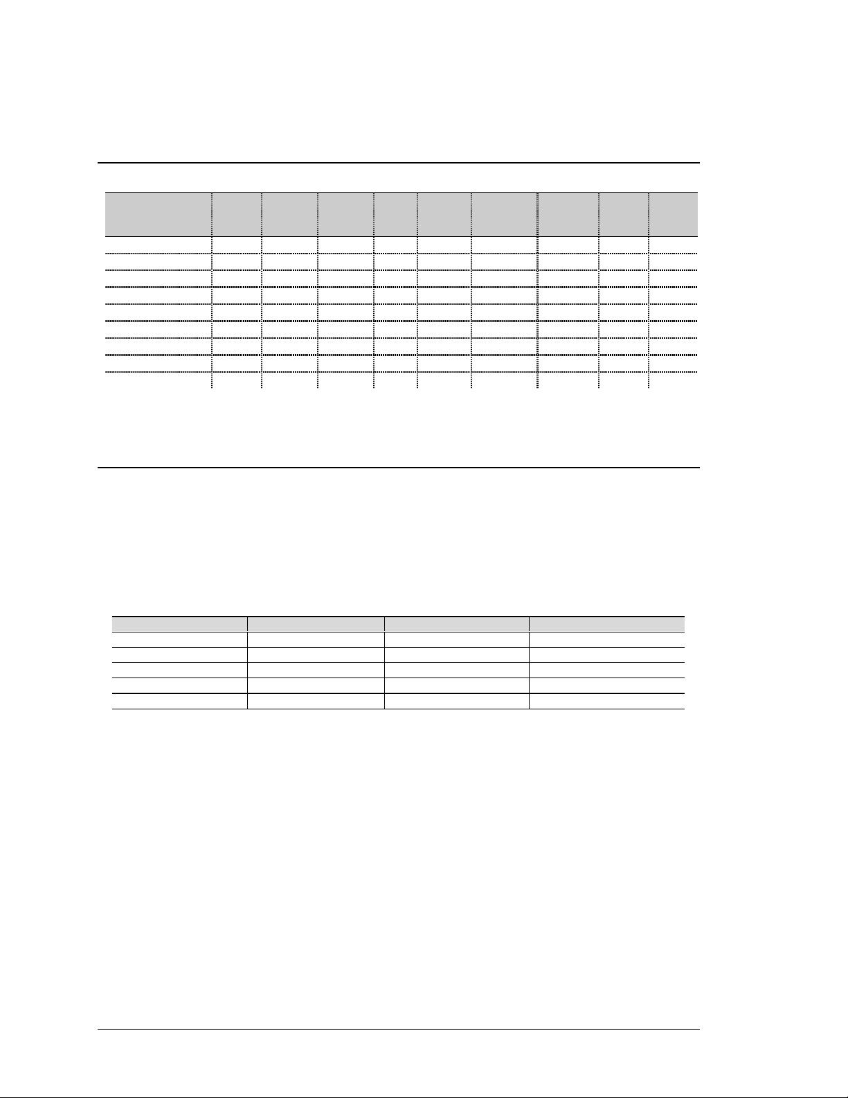
4. SUPPORTED TESTPOINT SOFTWARE CALLS
Board Type Start
A/D
Acquire
A/D
Sample
A/D
Start
D/A
Output
D/A
Set A/D
Trig
Immediate
Set
A/D Trig
Digital
Set A/D
Trig
Analog
Set A/D
Burst
Mode
PCI-5500MF Y Y Y N N Y Y N Y
PCI-501MF-0 Y Y Y N N Y Y N Y
PCI-5501MF-V Y Y Y Y Y Y Y N Y
PCI-5502MF-0 Y Y Y N N Y Y N Y
PCI-5502MF-V Y Y Y Y Y Y Y N Y
PCI-5503HR-0 Y Y Y N N Y Y N Y
PCI-5503HR-V Y Y Y Y Y Y Y N Y
PCI-5504HR-0 Y Y Y N N Y Y N Y
PCI-5504HR-V Y Y Y Y Y Y Y N Y
5. PCI-550X SERIES OPERATION
The PCI-550X Series supports most standard TestPoint “A/D Object” settings. In addition an extended
PCI-55XX A/D control object described below is provided to further enhances the A/D data collection
capabilities within TestPoint. For a listing of standard TestPoint A/D object support Refer to the
“Supported TestPoint Software Calls” section of this manual.
The PCI-550x Series of data acquisition boards includes five models; the following table describes the
main differences between these boards:
Product Name ADC Resolution Programmable Gains Number of Channels
PCI-5500MF 12-bit 100 kHz N/A 8 SE
PCI-5501MF 12-bit 100 kHz 1, 2, 4, 8 16 SE / 8 Diff
PCI-5502MF 12-bit 100 kHz 1, 10, 100, 1000 16 SE / 8 Diff
PCI-5503HR 16-bit 200 kHz 1, 2, 4, 8 16 SE / 8 Diff
PCI-5504HR 16-bit 200 kHz 1, 10, 100 16 SE / 8 Diff
The PCI-5500MF has 8 single-ended analog inputs multiplexed to a 12-bit A/D converter with maximum
throughput of 100 kHz, two counter input channels, two timer output channels and 16 lines of digital I/O.
The PCI-5501MF has 16 single-ended/pseudo-differential or 8 differential analog inputs multiplexed to a
12-bit A/D converter with maximum throughput of 100 kHz, programmable gains of 1, 2, 4 or 8, two
optional clocked 16-bit D/A voltage outputs, two counter input channels, two timer output channels and 48
lines of digital I/O. An eight 4-20mA current loop input option is available by using the TB-PCI-5500-8CL
screw terminal panel.
The PCI-5502MF is the same as the PCI-5501MF above, but with programmable gains of 1, 10, 100 or
1000.
The PCI-5503HR has 16 single-ended/pseudo-differential or 8 differential analog inputs multiplexed to a
16-bit A/D converter with maximum throughput of 200 kHz, programmable gains of 1, 2, 4 or 8, two
ADAC PCI Series TP ADAC-32 Driver
3
Page 7
optional clocked 16-bit D/A voltage outputs, two counter input channels, two timer output channels and 48
lines of digital I/O. An eight 4-20mA current loop input option is available by using the TB-PCI-5500-8CL
screw terminal panel.
The PCI-5504HR is the same as the PCI-5503HR above, but with programmable gains of 1, 10, 100.
All boards feature on-board digital calibration for both A/D and D/A, and a DMA engine for optimum
performance in a Windows environment. Board connections are terminated in a 68-pin “high density”
SCSC III connector at the rear of the PC.
The Channel range for the PCI-5500MF board is 0 to 7.
The Channel range for the PCI-5501MF/PCI-5502MF Series is from 0 to 15.
The Channel range for the PCI-5503HR/PCI-5504HR Series is from 0 to 15.
The PCI-5501MF and 5503HR provide programmable gains is 1, 2, 4 and 8.
The PCI-5502MF and PCI-5504HR provide programmable gains is 1, 10, 100 and 1000.
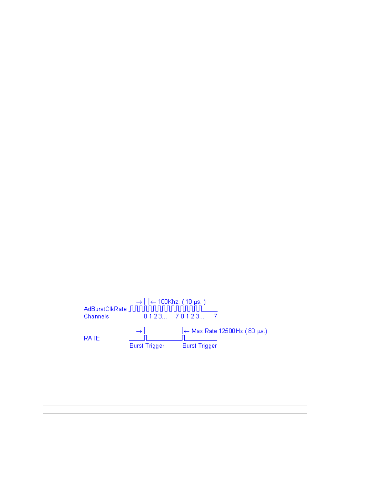
5.1 A/D BURST MODE ACQUISITION
This mode is only supported during StartAD or AcquireAD acquisition. The burst mode registers are used
to provide time interval between channel to channel conversions. The time interval between bursts is
obtained from the specified clocking source that is specified by the A/D rate parameter or external clock
input if the rate is set to 0.
The rate at which the burst conversions are clocked is defined by the TestPoint “Other A/D command,
BURSTRATE(value)” If the BURSTRATE value is not within the limits of the specific board’s
capabilities, an error will be reported by the driver. The rate parameter specified in the “A/D Object”
“StartA/D” or “AcquireA/D” specifies the time between bursts, and must not exceed the BURSTRATE
value divided by total number of channels (see example below).
BURSTRATE = 100000 10us. per sample .
A/D channel(s) = 0,1,2,3,4,5,6,7 Total channels equals 8
Max rate = BURSTRATE / nChannels 12500 = 100000 / 8
Max rate is the Rate parameter that is specified in the TestPoint Acquire or Start A/D command line.
If the rate parameter is set to 0 the Burst Trigger becomes external, but may be set by the TestPoint “Other
A/D command, EXTCLKEDGE(value) as EXT_FALLING_EDGE or EXT_RISING_EDGE”. The
EXTCLKEDGE must be issued just prior to each Start or Acquire command.
Note: The value specified by BURSTRATE is specified in hertz.
ADAC PCI Series TP ADAC-32 Driver
4
Page 8

5.1.1 A/D Internal Burst Triggering
For burst acquisition, TestPoint’s A/D Objects “StartA/D” or “AcquireA/D” rate parameter can be used to
program the on-board pacer clock to the rate at which burst scans are initiated. The rate parameter is the
exact frequency at which burst scans are initiated, i.e. if the rate were set to 1000 and the Channel(s) = 0, 1,
2, 3, 4, 5, 6, 7, the total number of A/D samples obtained in one second would be calculated as (8 channels
X 1000Hz.).
5.1.2 A/D External Burst Triggering
In burst mode acquisition, the (ADTGIN) input can be used to initiate a burst scan, each low to high
transition of the (ADTGIN) input will initiate a another burst scan.To select this option, set TestPoint’s
A/D Objects “StartA/D” or “AcquireA/D” rate parameter to 0 and “Set A/D trigger Immediate”.
5.2 A/D TRIGGERING METHODS
The TestPoint A/D Objects “StartA/D” and “AcquireA/D” “Set A/D trigger digital” allows an external
event to start the acquisition. In addition the TestPoint “Other A/D command, PRETRIGGER(value)” is
used to enable About mode acquisition when Set A/D trigger digital is enabled. In about mode the specified
number of PRETRIGGER(samples) is collected before the a trigger event and the rest of the samples after
the trigger. The external signal edge that triggers defaults to falling edge, but may be changed in the adactp.ini file using the ADAC Config program to either EXT_FALLING_EDGE or EXT_RISING_EDGE.
Note: The Trigger Source signal may also be output to the terminal connector/panel, to do this you must
modify the adac-tp.ini file using the ADAC Config program and set the TrigOutput setting to ENABLED
5.2.1 Post Triggering
In non-burst mode acquisition, the (ADTGIN) or (DATGIN) input can be used to start the acquisition, a
low to high transition of the ADTGIN connection will start the process. To do this set the TestPoint’s A/D
Objects “StartA/D”, “AcquireA/D” or “StartD/A” to “Set A/D Trigger Digital” just prior to each
“StartA/D”, “AcquireA/D” or “StartD/A”call.
5.3 D/A TRIGGERING METHODS
The TestPoint A/D Objects “StartD/A” can have an external event to start the acquisition as defined by the
D/A setting in the adac-tp.ini file. Using the ADAC Config program to modify the D/A trigger settings, the
trigger mode and edge may be configured.
5.4 A/D AND D/A CLOCKING METHODS
For non-burst acquisition, the rate parameter that TestPoint’s A/D Objects “StartA/D”, “AcquireA/D” and
StartD/A calls provide, is the rate in Hz at which the A/D or D/A conversions are clocked. For the A/D, the
rate is a multiple of the number of channels specified in the Channel(s)= parameter, i.e. if the rate were
equal to 1000 and the Channel(s) = 0, 1, 2, 3, 4, 5, 6, 7; the actual A/D clocking would be 8000 Hz, 1000
Hz per channel.
ADAC Series PCI boards also support an external clocking input connection that may be used to clock the
A/D conversions. To select the external clock input as the A/D clocking source, set the rate parameter in
TestPoint’s A/D Objects “StartA/D”, “AcquireA/D” or StartD/A to “0”. If the rate parameter is set to 0 the
signal edge that triggers defaults to falling edge, but may be set by the TestPoint “Other A/D command,
EXTCLKEDGE(value) as EXT_FALLING_EDGE or EXT_FALLING_EDGE”. The EXTCLKEDGE
must be issued just prior to each Start or Acquire command.
ADAC PCI Series TP ADAC-32 Driver
5
Page 9

Note: The A/D Clock Source signal may also be output to the terminal connector/panel, to do this you must
modify the adac-tp.ini file using the ADAC Config program and set the ClockOutput setting to ENABLED.
5.4.1 Internal Clocking
For non-burst acquisition, TestPoint’s A/D Objects “StartA/D”, “AcquireA/D” or “StartD/A” rate
parameter is used to program the on-board pacer clock to the rate at which the A/D conversions are
clocked.
For the A/D the rate is a multiple of the number of channels specified in the Channel(s)= parameter, i.e. if
the rate were equal to 1000 and the Channel(s) = 0, 1, 2, 3, 4, 5, 6, 7, the actual A/D clocking would be
8000 Hz, 1000 Hz. per channel.
5.4.2 External Clocking
In non-Burst mode acquisition, the (ADCLKIN) or (DACLKIN) input can be used to clock the A/D
conversions. To select the external clocking mode, set the TestPoint A/D Objects “StartA/D”,
“AcquireA/D” or “StartD/A” rate parameter to 0.
ADAC PCI Series TP ADAC-32 Driver
6
Page 10

6. ERROR CODES
In addition to the TestPoint error codes, the TP ADAC-32 driver reports custom error codes generated by
ADAC ADLIB Series driver which the TP ADAC-32 driver is based on. The error codes are extensive, and
should assist in solving most setup or configuration problems. See below for a complete list of ADLIB
error codes.
6.1 ADLIB ERROR CODES
ALERR_NOERRORS 1 No errors occurred during the call.
ALERR_NOT_SUPPORTED -1 The specified function or argument is not supported.
MEMORY
ALERR_MEMORY_LOW -100 memory allocation failed.
ALERR_DMA_MEMORY_LOW -101 DMA memory allocation failed increase.
ADACDMABUFFERSIZE in system.ini file.
GENERIC
ALERR_ARRAY_PTR -200 Invalid array pointer passed to function.
ALERR_STRING_PTR -201 Invalid string pointer passed to function.
ALERR_MAXSTRING -202 Input string size exceeds MAX length.
ALERR_MAXARRAY -203 Input array size exceeds MAX length.
ALERR_INVALID_STRINGLIST -204 Input string format invalid.
ALERR_DESTINATION_STRLEN -205 Input parameter destination string length is less than
the source string length.
ALERR_MINARRAY -206 Input array size exceeds MIN length.
ADAC PCI Series TP ADAC-32 Driver
7
Page 11

BOARD STRUCTURE
ALERR_BOARD_STRUCT_PTR -300 Invalid BOARD struct pointer.
ALERR_BOARD_ID -301 No BOARD struct for the specified Board ID exist.
ALERR_BOARD_CAPSFILE_STRPTR -302 The BOARD struct CAP's file pointer is invalid.
ALERR_BOARD_NOBOARDS -303 No board configurations found in .con file.
ALERR_BOARD_MAX_ADCCAPS -304 Max. ADC caps structures have been allocated.
ALERR_BOARD_MAX_DACCAPS -305 Max. DAC caps structures have been allocated.
ALERR_BOARD_MAX_DINCAPS -306 Max. DIN caps structures have been allocated.
ALERR_BOARD_MAX_DOTCAPS -307 Max. DOT caps structures have been allocated.
ALERR_BOARD_MAX_CTRCAPS -308 Max. CTR caps structures have been allocated.
ALERR_BOARD_MAXSTRING -309 The specified BOARD string exceeds max. length.
LOGICAL DEVICE HANDLES
ALERR_LHLD -400 The LHLD specified does not exist.
ALERR_LHLD_MAX -401 The maximum LHLD have already been allocated.
ADAC PCI Series TP ADAC-32 Driver
8
Page 12

LDS STRUCTURE
ALERR_LDS_STRUCT_PTR -500 Invalid LDS struct pointer.
ALERR_INTERNAL_LDS_TYPE -501 Unknown Logical Device Subsystem type.
ALERR_LDS_MAXSTRING -502 The LDS type string specified in a call to adlib
exceeds the maximum allowed length.
ALERR_LDS_MAXALLOCATED -503 The maximum LDS have been allocated.
ALERR_LDS_NOCAPS -504 No CAPS found.
ALERR_LDS_NOCAPSADC -505 No CAPSADC found.
ALERR_LDS_NOCAPSDAC -506 No CAPSDAC found.
ALERR_LDS_NOCAPSDIN -507 No CAPSDIN found.
ALERR_LDS_NOCAPSDOT -508 No CAPSDOT found.
ALERR_LDS_NOCAPSCTR -509 No CAPSCTR found.
ALERR_LDS_NOTSUPPORTED -510 Specified LDS is invalid.
CAPS STRUCTURE
ALERR_CAPS_TYPE -600 Unknown Capabilities Subsystem type.
ALERR_CAPS_STRUCT_PTR -601 Invalid CAPS struct pointer.
ALERR_CAPSADC_STRUCT_PTR -602 Invalid CAPSADC struct pointer.
ALERR_CAPSDAC_STRUCT_PTR -603 Invalid CAPSCTRIO struct pointer.
ALERR_CAPSDIGIO_STRUCT_PTR -604 Invalid CAPSDIGIO struct pointer.
ALERR_CAPSCTRIO_STRUCT_PTR -605 Invalid CAPSCTRIO struct pointer.
ADAC PCI Series TP ADAC-32 Driver
9
Page 13

ENVIRONMENT STRUCTURE
ALERR_ENV_STRUCT_PTR -700 Invalid ENV struct pointer.
ALERR_ENV_LOADED -701 The Environment is already loaded.
ALERR_ENV_NOTLOADED -702 The Environment is NOT loaded.
ALERR_ENV_MAXSTRING -703 The specified Environment is too long.
OPTIONS STRUCTURE
ALERR_OPTION_STRUCT_PTR -800 Invalid OPTIONS struct pointer.
ALERR_OPTION_STRPTR -801 Invalid option string pointer.
ALERR_OPTION_STRING -802 Invalid option string format.
ALERR_OPTION_NAME_STRPTR -803 Invalid option string name pointer.
ALERR_OPTION_NAME_STRING -804 Invalid option string name.
ALERR_OPTION_ID_STRING -805 Invalid option string ID.
ALERR_OPTION_CONFIG_TYPE -806 Invalid option string configuration type.
ALERR_OPTION_MAXSTRING -807 The option string exceeds the maximum
allowed length.
FILE I/O
ALERR_FILE_FOUND -900 The specified file can not be found.
ADAC PCI Series TP ADAC-32 Driver
10
Page 14

INI FILE
ALERR_INI_FILEEXIST -1000 The INFO file (.INI) can not be found.
ALERR_INI_PATH_STRPTR -1001 Invalid .INI string pointer.
ALERR_INI_SECTION_STRPTR -1002 Invalid .INI [SECTION] string pointer.
ALERR_INI_ENTRY_STRPTR -1003 Invalid .INI ENTRY string pointer.
ALERR_INI_SECTION_UNKNOWN -1004 Unknown .INI [SECTION].
ALERR_INI_BOARDID_RANGE -1005 Invalid .INI BoardId setting.
ALERR_INI_DTM_STRING -1006 Invalid .INI DataTransMethod setting.
ALERR_INI_CM_STRING -1007 Invalid .INI CycleMode setting.
ALERR_INI_DMAMODE_STRING -1008 Invalid .INI DmaMode setting.
ALERR_INI_DMACHAN_STRING -1009 Invalid .INI DmaChan setting.
ALERR_INI_IRQMODE_STRING -1010 Invalid .INI IrqMode setting.
ALERR_INI_IRQLEVEL_STRING -1011 Invalid .INI IrqLevel setting.
ALERR_INI_ARBREINIT_STRING -1012 Invalid .INI ArbReinit setting.
ALERR_INI_LOGERRORS_STRING -1013 Invalid .INI LogErrors setting.
ALERR_INI_ERRONBUFFOVERRUN_STRING -1014 Invalid .INI
ErrorOnBufferOverrun setting.
ALERR_INI_ERRONRELRUNNING_STRING -1015 Invalid .INI
ErrorOnReleaseRunning setting.
ALERR_INI_BUFFERSIZE_LOW -1016 Invalid .INI BufferSize setting.
ALERR_INI_NUMBUFFER_LOW -1017 Invalid .INI NumBuffers setting.
ALERR_INI_BUFFERNOTIFYMETHOD_STRING -1018 Invalid .INI
BufferNotificationMethod setting.
ALERR_INI_AUTOINITBUFFERS_STRING -1019 Invalid .INI AutoInitBuffers setting.
ALERR_INI_ERRONTRIGGEROVERRUN_STRING -1020 Invalid .INI ErrOnTriggerOverrun
setting.
ADAC PCI Series TP ADAC-32 Driver
11
Page 15

INI FILE - continued
ALERR_INI_MINSTARTCHAN_STRING -1100 Invalid .INI MinStartChan setting.
ALERR_INI_MAXENDCHAN_STRING -1101 Invalid .INI MaxEndChan setting.
ALERR_INI_SIGNALPATH_STRING -1102 Invalid .INI SignalPath setting.
ALERR_INI_INPUTCONFIG_STRING -1103 Invalid .INI InputConfig setting.
ALERR_INI_CLKMODE_STRING -1104 Invalid .INI ClkMode setting.
ALERR_INI_CLKSOURCE_STRING -1105 Invalid .INI ClkSource setting.
ALERR_INI_CLKSOURCESIGNAL_STRING -1106 Invalid .INI ClkSourceSignal setting.
ALERR_INI_CLKRATE_STRING -1107 Invalid .INI ClkRate setting.
ALERR_INI_CLKRATE_RANGE -1108 Invalid .INI ClkRate range.
ALERR_INI_CLKRATEUNITS_STRING -1109 Invalid .INI ClkRateUnits setting.
ALERR_INI_BURSTLENGTH_STRING -1110 Invalid .INI BurstLength setting.
ALERR_INI_BURSTLENGTH_RANGE -1111 Invalid .INI BurstLength range.
ALERR_INI_BURSTRATE_STRING -1112 Invalid .INI BurstRate setting.
ALERR_INI_BURSTRATE_RANGE -1113 Invalid .INI BurstRate range.
ALERR_INI_BURSTRATEUNITS_STRING -1114 Invalid .INI BurstRateUnits setting.
ALERR_INI_TRIGMODE_STRING -1115 Invalid .INI TrigMode setting.
ALERR_INI_TRIGSRC_STRING -1116 Invalid .INI TrigSource setting.
ALERR_INI_TRIGSRCSIGNAL_STRING -1117 Invalid .INI TrigSourceSignal setting.
ALERR_INI_TRIGRATE_STRING -1118 Invalid .INI TrigRate setting.
ALERR_INI_TRIGRATE_RANGE -1119 Invalid .INI MinTrigRate or MaxTrigRate
setting.
ALERR_INI_TRIGRATEUNITS_STRING -1120 Invalid .INI TrigRateUnits setting.
ALERR_INI_DATACODE_STRING -1121 Invalid .INI DataCode setting.
ALERR_INI_DATAOFFSET_STRING -1122 Invalid .INI DataOffset setting.
ALERR_INI_DATASPAN_STRING -1123 Invalid .INI DataSpan setting.
ALERR_INI_DATARANGE_STRING -1124 Invalid .INI DataRange setting.
ADAC PCI Series TP ADAC-32 Driver
12
Page 16

ALERR_INI_OUTPUTCONFIG_STRING -1125 Invalid .INI OutputConfig setting.
INI FILE - continued
ALERR_INI_EXPPANEL_STRING -1126 Invalid .INI ExpansionPanel n setting.
ALERR_INI_POSTSAMPLECOUNT_STRING -1127 Invalid .INI PostSampleCounts setting.
ALERR_INI_POSTSAMPLECOUNT_RANGE -1128 Invalid .INI PostSampleCounts range.
ALERR_INI_GATESRC_STRING -1129 Invalid .INI GatrSource setting.
ALERR_INI_GATESRCLEVEL_STRING -1130 Invalid .INI GateSourceLevel setting.
ALERR_INI_BURSTMODE_ STRING -1131 Invalid .INI BurstMode setting.
ALERR_INI_FILTERTYPE_ STRING -1132 Invalid .INI Filtertype setting.
ALERR_INI_FILTERFREQ_ STRING -1133 Invalid .INI FilterFreq setting.
ALERR_INI_ FILTERFREQ _ RANGE -1134 Invalid .INI FilterFreq range.
ALERR_INI_HANDSHAKE_ STRING -1135 Invalid .INI HandShake setting.
ALERR_INI_PORTRESOLUTION_ STRING -1136 Invalid .INI PortResolution setting.
ALERR_INI_ PORTMASK _ STRING -1137 Invalid .INI PortMask setting.
ALERR_INI_ PORTRMASK_ RANGE -1138 Invalid .INI PortMask range.
ALERR_INI_ CTRMODE_ STRING -1139 Invalid .INI CtrMode setting.
ALERR_INI_ CTRRATEUNITS_ STRING -1140 Invalid .INI CtrRateUnits setting.
ALERR_INI_ CTRRATE_ STRING -1141 Invalid .INI CtrRate setting.
ALERR_INI_ PACKEDDATA_ STRING -1142 Invalid .INI PackedData setting.
ALERR_INI_ CLKOUTPUT_ STRING -1143 Invalid .INI ClockOutput setting.
ALERR_INI_ TRIGOUTPUT _ STRING -1144 Invalid .INI TrigOutput setting.
CAPABILITIES FILE
ALERR_CAPS_FILEEXIST -2000 The Capabilities (.CAP) can not be found.
ALERR_CAPS_MFG_STRING -2001 Invalid .CAP manufacture setting.
ALERR_CAPS_MODEL_STRING -2002 Invalid .CAP model setting.
ADAC PCI Series TP ADAC-32 Driver
13
Page 17

BOARD
ALERR_CAPS_IOBASEADDRSEL_STRING -2100 Invalid .CAP IoBaseAddrSelect setting.
ALERR_CAPS_MINIOBASEARRR_STRING -2101 Invalid .CAP MinIoBaseAddress setting.
ALERR_CAPS_MAXIOBASEARRR_STRING -2102 Invalid .CAP MaxIoBaseAddress setting.
DRIVER
ALERR_CAPS_DRIVERVERSION_STRING -2200 Invalid .CAP DriverVersion setting.
ALERR_CAPS_DRIVERNAME_STRING -2201 Invalid .CAP DriverName setting.
ALERR_CAPS_BOARDVERSION_STRING -2202 Invalid .CAP BoardVersionSupport setting.
ALERR_CAPS_BOARDIDSUPPORT_STRING -2203 Invalid .CAP BoardVersionId setting.
ALERR_CAPS_VERSION_STRING -2204 Invalid .CAP file Version setting.
ADAC PCI Series TP ADAC-32 Driver
14
Page 18

COMMON DEVICE SETTINGS
ALERR_CAPS_IRQSHAREABLE_STRING -2300 Invalid .CAP IrqShareable setting.
ALERR_CAPS_DTM_STRING -2301 Invalid .CAP DataTransMethod setting.
ALERR_CAPS_DTM_ENTRY -2302 CAP DataTransMethod entry does not exist.
ALERR_CAPS_CM_STRING -2303 Invalid .CAP CycleMode setting.
ALERR_CAPS_CM_ENTRY -2304 CAP CycleMode entry does not exist.
ALERR_CAPS_BUFFERNOTIFYMETHOD_STRING -2305 Invalid .CAP buffer notification
setting.
ALERR_CAPS_DMAMODE_STRING -2307 Invalid .CAP DmaMode setting.
ALERR_CAPS_DMACHAN_STRING -2308 Invalid .CAP DmaChan setting.
ALERR_CAPS_IRQMODE_STRING -2309 Invalid .CAP IrqMode setting.
ALERR_CAPS_IRQLEVEL_STRING -2310 Invalid .CAP IrqLevel setting.
ALERR_CAPS_BUFFERSUPPORT_STRING -2311 Invalid .CAP BoardVersionId setting
ALERR_CAPS_MINBUFFERS_STRING -2312 Invalid .CAP MinStartChan setting.
ALERR_CAPS_MAXBUFFERS_STRING -2313 Invalid .CAP MaxEndChan setting.
ALERR_CAPS_MINBUFFERSIZE_STRING -2314 Invalid .CAP Min buffer size setting.
ALERR_CAPS_MAXBUFFERSIZE_STRING -2315 Invalid .CAP Max buffer size setting.
ALERR_CAPS_PACKEDFIFO_STRING 2316 Invalid .CAP PackedFifoSupport setting.
ADAC PCI Series TP ADAC-32 Driver
15
Page 19

ADC
ALERR_CAPS_GAIN_STRING -2351 Invalid .CAP GAIN string format.
ALERR_CAPS_MINSTARTCHAN_STRING -2352 Invalid .CAP MinStartChan setting.
ALERR_CAPS_MAXENDCHAN_STRING -2353 Invalid .CAP MaxEndChan setting.
ALERR_CAPS_ARBCHAN_STRING -2354 Invalid .CAP ArbChan setting.
ALERR_CAPS_ARBGAIN_STRING -2355 Invalid .CAP ArbGain setting.
ALERR_CAPS_CLKMODE_STRING -2356 Invalid .CAP ClkMode setting.
ALERR_CAPS_CLKSOURCE_STRING -2357 Invalid .CAP ClkSource setting.
ALERR_CAPS_CLKSOURCESIGNAL_STRING -2358 Invalid .CAP ClkSourceSignal setting.
ALERR_CAPS_MINCLKRATE_STRING -2359 Invalid .CAP MinClkRate setting.
ALERR_CAPS_MAXCLKRATE_STRING -2360 Invalid .CAP MaxClkRate setting.
ALERR_CAPS_MINBURSTLENGTH_STRING -2361 Invalid .CAP MinBurstLength setting.
ALERR_CAPS_MAXBURSTLENGTH_STRING -2362 Invalid .CAP MaxBurstLength setting.
ALERR_CAPS_MINBURSTRATE_STRING -2363 Invalid .CAP MinBurstRate setting.
ALERR_CAPS_MAXBURSTRATE_STRING -2364 Invalid .CAP MaxBurstRate setting.
ALERR_CAPS_TRIGMODE_STRING -2365 Invalid .CAP TrigMode setting.
ALERR_CAPS_TRIGSRC_STRING -2366 Invalid .CAP TrigSource setting.
ALERR_CAPS_TRIGSRCSIGNAL_STRING -2367 Invalid .CAP TrigSourceSignal setting.
ALERR_CAPS_MINTRIGRATE_STRING -2368 Invalid .CAP MinTrigRate setting.
ALERR_CAPS_MAXTRIGRATE_STRING -2369 Invalid .CAP MaxTrigRate setting.
ALERR_CAPS_CJ_STRING -2370 Invalid .CAP CJ setting.
ALERR_CAPS_ARBCJ_STRING -2371 Invalid .CAP ArbCj setting.
ALERR_CAPS_DATACODE_STRING -2372 Invalid .CAP DataCode setting.
ALERR_CAPS_DATAOFFSET_STRING -2373 Invalid .CAP DataOffset setting.
ALERR_CAPS_DATASPAN_STRING -2374 Invalid .CAP DataSpan setting.
ALERR_CAPS_FIFOSIZE_STRING -2375 Invalid .CAP FifoSize setting.
ALERR_CAPS_DATARANGE_STRING -2376 Invalid .CAP DataRange setting.
ADAC PCI Series TP ADAC-32 Driver
16
Page 20

ADC - continued
ALERR_CAPS_OUTPUTCONFIG_STRING -2377 Invalid .CAP OutputConfig setting.
ALERR_CAPS_MAXEXPPANELS_STRING -2378 Invalid .CAP MaxNumExpPanels setting.
ALERR_CAPS_EXPPANEL_STRING -2379 Invalid .CAP ExpPanel setting.
ALERR_CAPS_MAXEXPPANELS_MAX -2380 Invalid .CAP MaxNumExpPanels too High.
ALERR_CAPS_BYTEPERSMPL_STRING -2381 Invalid .CAP BytesPerSample setting.
ALERR_CAPS_MINPOSTSAMPLE_STRING -2382 Invalid .CAP MinPostSamples setting.
ALERR_CAPS_MAXPOSTSAMPLE_STRING -2383 Invalid .CAP MaxPostSamples setting.
ALERR_CAPS_GATESRC_STRING -2384 Invalid .CAP GateSource setting.
ALERR_CAPS_GATESRCLEVEL_STRING -2385 Invalid .CAP GateSourceLevel setting.
ALERR_CAPS_BURSTMODE_STRING -2386 Invalid .CAP BurstMode setting.
ALERR_CAPS_SIGNALPATH_STRING -2387 Invalid .CAP SignalPath setting.
ALERR_CAPS_INPUTCONFIG_STRING -2388 Invalid .CAP InputConfig setting.
ALERR_CAPS_DATAMASK_STRING -2389 Invalid .CAP DataMask setting.
ALERR_CAPS_FILTERTYPE_STRING -2390 Invalid .CAP FilterType setting.
ALERR_CAPS_MINFILTERFREQ_STRING -2391 Invalid .CAP MinFilterFreq setting.
ALERR_CAPS_MAXFILTERFREQ_STRING -2392 Invalid .CAP MaxFilterFreq setting.
ALERR_CAPS_HANDSHAKE_STRING -2393 Invalid .CAP HandShake setting.
ALERR_CAPS_PORTRESOLUTION_STRING -2394 Invalid .CAP PortResolution setting.
ALERR_CAPS_MINPORTMASK_STRING -2395 Invalid .CAP MinPortMask setting.
ALERR_CAPS_MAXPORTMASK_STRING -2396 Invalid .CAP MaxPortMask setting.
ALERR_CAPS_CLKOUTPUT_STRING - 2397 Invalid .CAP ClockOutput setting.
ALERR_CAPS_TRIGOUTPUT_STRING - 2398 Invalid .CAP TrigOutput setting.
ALERR_CAPS_INPUTCONFIG_STRING - 2399 Invalid .CAP InputConfig setting.
ALERR_CAPS_DATAOFFSET_STRING - 2400 Invalid .CAP DataOffset setting.
ALERR_CAPS_CTRMODE_STRING - 2401 Invalid .CAP CtrMode setting.
ALERR_CAPS_MINRATE_STRING - 2402 Invalid .CAP MinRate setting.
ADAC PCI Series TP ADAC-32 Driver
17
Page 21

ADC - continued
ALERR_CAPS_MAXRATE_STRING - 2403 Invalid .CAP MaxRate setting.
CONFIGURATION FILE
ALERR_CON_FILEEXIST -3000 The Configuration (.CON) can not be found.
ALERR_CON_FILE_MAXSTRING -3001 The (.CON) file string exceeds the
maximum allowed length.
ALERR_CON_FILE_STRPTR -3002 Invalid .CON file string pointer.
ALERR_CON_BOARDSECTION_STRPTR -3003 Invalid .CON board section pointer.
ALERR_CON_BOARDSECTION_STRING -3004 Invalid .CON board section string
ALERR_CON_BOARDID_SAME -3005 Invalid .CON BoardId setting.
ALERR_CON_BOARDID_RANGE -3006 Invalid .CON BoardId setting.
ALERR_CON_IOBASEADDR_STRING -3007 Invalid .CON IoBaseAddr setting.
ALERR_CON_BOARDCAPSFILE_STRING -3008 Invalid .CON capabilities file setting.
ALERR_CON_DRVPATH_STRING -3009 Invalid .CON driver Path setting.
ALERR_SYSTEMDRV_STRING -3010 Invalid .CON System driver setting.
ADAC PCI Series TP ADAC-32 Driver
18
Page 22

DEVICE SUBSYSTEM CHANNELS
ALERR_CHANLIST_LISTTYPE -4000 Invalid Channel list struct list lType, is it an
Array or String list.
ALERR_CHANLIST_STRPTR -4001 Invalid Channel list string pointer.
ALERR_CHANLIST_STRING -4002 Invalid Channel list string.
ALERR_CHANLIST_MAXSTRLEN -4003 Invalid Channel list string length.
ALERR_CHANLIST_ARRAYPTR -4004 Invalid Channel list array pointer.
ALERR_CHANLIST_ARRAY_LENTHPTR -4005 Invalid Channel list array length pointer.
ALERR_CHANLIST_MAXARRAYLEN -4006 Invalid Channel list array length.
ALERR_CHANLIST_MINCHAN -4007 Invalid Channel in list.
ALERR_CHANLIST_MAXCHAN -4008 Invalid Channel in list.
ALERR_CHANLIST_NONSEQ -4009 Non-sequential Channels are not supported.
ALERR_GLOBALGAIN_STRPTR -4010 Invalid Global Gain string pointer.
ALERR_GLOBALGAIN_GAIN -4011 Invalid Gain type.
ALERR_CHANGAINLIST_LISTTYPE -4050 Invalid Channel list struct list lType, is it an
Array or String list.
ALERR_CHANGAINLIST_STRPTR -4051 Invalid Channel list string pointer.
ALERR_CHANGAINLIST_STRING -4052 Invalid Channel list string.
ALERR_CHANGAINLIST_MAXSTRLEN -4053 Invalid Channel list string length.
ALERR_CHANGAINLIST_ARRAYPTR -4054 Invalid Channel list array pointer.
ALERR_CHANGAINLIST_ARRAY_LENTHPTR -4055 Invalid Channel list array length pointer.
ALERR_CHANGAINLIST_MAXARRAYLEN -4056 Invalid Channel list array length.
ALERR_CHANGAINLIST_MINCHAN -4057 Invalid Channel in list.
ALERR_CHANGAINLIST_MAXCHAN -4058 Invalid Channel in list.
ALERR_CHANGAINLIST_NONSEQ -4059 Non-sequential Channels are not supported.
ALERR_CHANGAINLIST_SYNTAX -4060 Invalid ChanGainList syntax.
ALERR_CHANGAINLIST_ARBGAINS -4061 Aribitrary Gains are not supported.
ALERR_CHANGAINLIST_GAINTYPE -4062 Invalid Gain type.
ADAC PCI Series TP ADAC-32 Driver
19
Page 23

DEVICE SUBSYSTEM EXPANSION PANEL GAINS
ALERR_EXPPANELGAINLIST_LISTTYPE -4100 Invalid ExpPanelGainList structure list lType.
ALERR_EXPPANELGAINLIST_STRPTR -4101 Invalid ExpPanelGainList string pointer.
ALERR_EXPPANELGAINLIST_STRING -4102 Invalid ExpPanelGainList string.
ALERR_EXPPANELGAINLIST_MAXSTRLEN -4103 Invalid ExpPanelGainList string length.
ALERR_EXPPANELGAINLIST_GAINSETTING -4104 Invalid ExpPanelGainList gain setting.
ALERR_EXPPANELGAINLIST_ARRAYPTR -4105 Invalid ExpPanelGainList array pointer.
ALERR_EXPPANELGAINLIST_ARRAY_LENGTHPTR -4106 Invalid ExpPanelGainList array
length pointer.
ALERR_EXPPANELGAINLIST_MAXARRAYLEN -4107 Invalid ExpPanelGainList array
length.
ALERR_EXPPANELGAINLIST_MINCHAN -4108 Invalid ExpPanelGainList channel.
ALERR_EXPPANELGAINLIST_MAXCHAN -4109 Invalid ExpPanelGainList channel.
ALERR_EXPPANELGAINLIST_SYNTAX -4110 Invalid ExpPanelGainList syntax.
ADAC PCI Series TP ADAC-32 Driver
20
Page 24

DEVICE SUBSYSTEM INPUT CONFIGURATION LIST
ALERR_INPUTCONFIG_LISTTYPE -4120 Invalid InputConfig structure list lType.
ALERR_ INPUTCONFIG _STRPTR -4121 Invalid InputConfig string pointer.
ALERR_ INPUTCONFIG _STRING -4122 Invalid InputConfig string.
ALERR_ INPUTCONFIG _MAXSTRLEN -4123 Invalid InputConfig string length.
ALERR_ INPUTCONFIG _GAINSETTING -4124 Invalid InputConfig gain setting.
ALERR_ INPUTCONFIG _ARRAYPTR -4125 Invalid InputConfig array pointer.
ALERR_ INPUTCONFIG _ARRAY_LENGTHPTR -4126 Invalid InputConfig array length pointer.
ALERR_ INPUTCONFIG _MAXARRAYLEN -4127 Invalid InputConfig array length.
ALERR_ INPUTCONFIG _MINCHAN -4128 Invalid InputConfig min channel specified.
ALERR_ INPUTCONFIG _MAXCHAN -4129 Invalid InputConfig max channel specified.
ALERR_ INPUTCONFIG _SYNTAX -4130 Invalid InputConfig list syntax
ALERR_GLOBAL INPUTCONFIG _STRPTR -4131 Invalid global InputConfig string pointer.
ALERR_GLOBAL INPUTCONFIG_TYPE -4132 Invalid global InputConfig type
DEVICE SUBSYSTEM DATA OFFSET LIST
ALERR_DATAOFFSET_LISTTYPE -4140 Invalid DataOffset structure list lType.
ALERR_ DATAOFFSET _STRPTR -4141 Invalid DataOffset string pointer.
ALERR_ DATAOFFSET _STRING -4142 Invalid DataOffset string.
ALERR_ DATAOFFSET _MAXSTRLEN -4143 Invalid DataOffset string length.
ALERR_ DATAOFFSET _ GAINSETTING -4144 Invalid DataOffset gain setting.
ALERR_ DATAOFFSET _ARRAYPTR -4145 Invalid DataOffset array pointer.
ALERR_ DATAOFFSET _ARRAY_LENGTHPTR -4146 Invalid DataOffset array length pointer.
ALERR_ DATAOFFSET _MAXARRAYLEN -4147 Invalid DataOffset array length.
ALERR_ DATAOFFSET _MINCHAN -4148 Invalid DataOffset min channel specified.
ALERR_ DATAOFFSET _MAXCHAN -4149 Invalid DataOffset max channel specified.
ALERR_ DATAOFFSET _SYNTAX -4150 Invalid DataOffset list syntax
ADAC PCI Series TP ADAC-32 Driver
21
Page 25

DEVICE SUBSYSTEM DATA OFFSET LIST (con’t)
ALERR_GLOBAL DATAOFFSET _STRPTR -4151 Invalid global DataOffset string pointer.
ALERR_GLOBAL DATAOFFSET _TYPE -4152 Invalid global DataOffset type
DEVICE SUBSYSTEM EXPANSION PANEL
ALERR_EXPPANELLIST_LISTTYPE -4200 Invalid ExpPanelList structure list lType.
ALERR_EXPPANELLIST_STRPTR -4201 Invalid ExpPanelList string pointer.
ALERR_EXPPANELLIST_STRING -4202 Invalid ExpPanelList string.
ALERR_EXPPANELLIST_MAXSTRLEN -4203 Invalid ExpPanelList string length.
ALERR_EXPPANELLIST_SETTING -4204 Invalid ExpPanelList gain setting.
ALERR_EXPPANELLIST_ARRAYPTR -4205 Invalid ExpPanelList array pointer.
ALERR_EXPPANELLIST_ARRAY_LENGTHPTR -4206 Invalid ExpPanelList array length pointer.
ALERR_EXPPANELLIST_MAXARRAYLEN -4207 Invalid ExpPanelList array length.
ALERR_EXPPANELLIST_MAXPANELS -4208 Invalid Number of ExpPanels specified.
ALERR_EXPPANELLIST_PANELTYPE -4209 Invalid ExpPanelList panel type.
ADAC PCI Series TP ADAC-32 Driver
22
Page 26

DEVICE SUBSYSTEM THERMOUCOUPLES
ALERR_CJLIST_LISTTYPE -4401 Invalid CJ structure list lType.
ALERR_CJLIST_STRPTR -4402 Invalid CJ string pointer.
ALERR_CJLIST_STRING -4403 Invalid CJ string.
ALERR_CJLIST_MAXSTRLEN -4404 Invalid CJ string length.
ALERR_CJLIST_ARRAYPTR -4405 Invalid CJ array pointer.
ALERR_CJLIST_ARRAY_LENGTHPTR -4406 Invalid CJ array length pointer.
ALERR_CJLIST_MAXARRAYLEN -4407 Invalid CJ array length.
ALERR_CJLIST_ARBCJ -4408 Arbitrary CJs are not supported.
ALERR_CJLIST_MINCHAN -4409 Invalid CJ channel specified.
ALERR_CJLIST_MAXCHAN -4410 Invalid CJ channel specified.
ALERR_CJLIST_CJTYPE -4411 Invalid CJ type
ALERR_CJLIST_SYNTAX -4412 Invalid CJ list syntax
ALERR_GLOBALCJ_STRPTR -4413 Invalid global CJ string pointer.
ALERR_GLOBALCJ_CJTYPE -4414 Invalid global CJ type
TRIGGERS
ALERR_TRIGGERMODE_UNSUPPORTED -4500 Trigger Mode is not supported.
ALERR_TRIGGERMODE_OPTION -4501 Specified trigger mode source is not
supported.
ALERR_TRIGGER_RATELOW -4502 Invalid trigger rate specified.
ALERR_TRIGGER_RATEHIGH -4503 Invalid trigger rate specified.
ALERR_TRIGGER_MINPOSTSAMPLECOUNT -4504 Invalid post sample count specified.
ALERR_TRIGGER_MAXPOSTSAMPLECOUNT -4505 Invalid post sample count specified.
ALERR_TRIGGER_POSTSMPLCNT_BUFFSIZE -4506 Specified Post sample counts > bufferSize.
ADAC PCI Series TP ADAC-32 Driver
23
Page 27

TRIGGER SOURCES
ALERR_TRIGGERSOURCE_OPTION -4507 Specified Trigger source is not supported.
ALERR_TRIGGERSOURCE_UNSUPPORTED -4510 Trigger sources is not supported.
TRIGGER SIGNALS
ALERR_TRIGGERSOURCESIGNAL_UNSUPPORTED -4508 Triggering is not supported.
ALERR_TRIGGERSOURCESIGNAL_OPTION -4509 Specified trigger signal source is
not supported.
TRIGGER OUTPUTS
ALERR_TRIGGERSOUTPUT_UNSUPPORTED - 4511 Triggering Output is not supported.
ALERR_TRIGGERSOUTPUT_OPTION -4512 Specified trigger Output is not
supported.
CLOCKING
ALERR_CLOCKING_UNSUPPORTED -4600 Clocking is not supported.
ALERR_CLOCKING_OPTION -4601 Specified Clock option is not supported.
ALERR_CLOCKING_RATELOW -4602 Invalid clock rate specified.
ALERR_CLOCKING_RATEHIGH -4603 Invalid clock rate specified.
CLOCK SIGNALS
ALERR_CLOCKSIGNAL_UNSUPPORTED -4604 Clocking is not supported.
ALERR_CLOCKSIGNAL_OPTION -4605 Specified Clock option is not supported.
ADAC PCI Series TP ADAC-32 Driver
24
Page 28

CLOCK OUTPUTS
ALERR_CLOCKSOUTPUT_UNSUPPORTED -4606 ClockOutput is not supported.
ALERR_CLOCKOUTPUT_OPTION -4607 Specified ClockOutput is not supported.
DATA CODE
ALERR_DATACODE_UNSUPPORTED -4700 Data Coding is not supported.
ALERR_DATACODE -4701 Specified Data Code option is not valid.
DATA OFFSET
ALERR_DATAOFFSET_UNSUPPORTED -4800 Data Offset is not supported.
ALERR_DATAOFFSET -4801 Specified Data Offset option is not valid.
DMA
ALERR_DMA_MODES_UNSUPPORTED -4900 DMA Modes are not supported.
ALERR_DMA_MODE -4901 Specified DMA Modes option is not valid.
ALERR_DMA_CHANS_UNSUPPORTED -4902 DMA Channels are not supported.
ALERR_DMA_CHAN -4903 Specified DMA Channel option is not valid.
ALERR_DMA_INUSE -4904 Specified DMA Channel is already in use.
ALERR_SETDMASTATUS_FLAG -4905 The status flag specified is unknown.
ADAC PCI Series TP ADAC-32 Driver
25
Page 29

INTERRUPTS
ALERR_IRQ_LEVELS_UNSUPPORTED -5000 IRQ Levels are not supported.
ALERR_IRQ_LEVEL -5001 Specified IRQ Level option is not valid.
ALERR_IRQ_INUSE -5002 Specified IRQ Level is already in use.
ALERR_SETIRQSTATUS_FLAG -5003 The status flag specified is
unknown.
ALERR_SETIRQSTATUS_OWNER -5004 Invalid IRQ owner setting status flags.
SIGNAL PATHS
ALERR_SIGNALPATH_UNSUPPORTED -5100 Signal Paths are not supported.
ALERR_SIGNALPATH -5101 Specified Signal Path option is not valid.
DATA TRANSFER METHOD
ALERR_DTM_UNSUPPORTED -5200 DTM Methods are not supported.
ALERR_DTM -5201 Specified DTM Method option is not valid.
CYCLE MODE
ALERR_CM_UNSUPPORTED -5300 CM Methods are not supported.
ALERR_CM -5301 Specified CM option is not valid.
ALERR_CM_NUMBUFFERS -5302 Selected CM option is not valid for the
number of buffers specified.
DATA SPAN
ALERR_DATASPAN_UNSUPPORTED -5400 Data Span is not supported.
ALERR_DATASPAN -5401 Specified Data Span option is not valid.
ADAC PCI Series TP ADAC-32 Driver
26
Page 30

DATA RANGE
ALERR_DATARANGE_UNSUPPORTED -5500 Data Range is not supported.
ALERR_DATARANGE -5501 Specified Data Range option is not valid.
INPUT CONFIG
ALERR_INPUTCONFIG_UNSUPPORTED -5600 Input Config is not supported.
ALERR_INPUTCONFIG -5601 Specified Input Config option is not valid.
OUTPUT CONFIG
ALERR_OUTPUTCONFIG_UNSUPPORTED -5700 Signal Paths are not supported.
ALERR_OUTPUTCONFIG -5701 Specified Signal Path option is not valid.
BUFFER NOTIFICATION METHOD
ALERR_SETBUFFDONEHANDLER_UNSUPPORTED -5800 Buffer Notification Methods are
not supported.
ALERR_SETBUFFDONEHANDLER_METHOD -5801 Specified buffer Notification
Method option is not valid.
ALERR_SETBUFFDONEHANDLERMSG_UNSUPPORTED -5802 Buffer PostMessage
Notification is not supported.
ALERR_SETBUFFDONEHANDLERFUNC_UNSUPPORTED -5803 Buffer CallBack
Notifications are not supported.
ALERR_ SETBUFFDONEHANDLERMSGPARAMS_UNSUPPORTED -5804 Buffer
PostMessageParams are
not supported.
START DEVICE
ALERR_DEVICE_BUSY -5900 The device is already running.
ALERR_DEVICE_UNINITIALIZED -5901 The device is not initialized.
ADAC PCI Series TP ADAC-32 Driver
27
Page 31

DATA BUFFER CONTROL ERRORS
ALERR_BUFFER_HANDLER -6000 Invalid handler specified.
ALERR_BUFFER_SIZE -6001 Invalid buffer size specified.
ALERR_BUFFER_NUMBEROF -6002 Invalid number of buffers specified.
ALERR_BUFFER_TYPE -6003 Invalid buffer type specified.
ALERR_BUFFER_NOTIFY_METHOD -6004 Invalid buffer notification method specified.
ALERR_BUFFER_NOTSUPPORTED -6005 Buffer(s) are not supported on this LHLD.
ALERR_BUFFER_POINTER -6006 Buffer pointer equal to NULL.
ALERR_BUFFER_ERROR -6007 An error condition occured in the previous
buffer making the next DONE_BUFFER
unavailable.
ALERR_DONEBUFFER_NOTREADY -6008 The next buffer has not completed.
ALERR_BUFFER_STARTPOINT -6009 The specified buffer StartPoint position
number is out of range for the available
buffer size.
ALERR_BUFFER_MAXCOUNT -6010 The specified number of buffer counts
exceeds the available buffer size.
ALERR_BUFFER_STATUS_PTR -6011 Invalid LPDATABUFFSTATUS specified.
ALERR_BUFFER_NUMBER -6012 Invalid buffer number specified.
ALERR_BUFFER_INTERNAL -6013 Unable to locate specified buffer.
BURST MODE CONTROL ERRORS
ALERR_BURSTMODE_UNSUPPORTED -7000 Burst mode is not supported on this LHLD.
ALERR_BURSTMODE_OPTION -7001 Invalid burst mode specified.
ALERR_BURST_RATELOW -7002 Burst mode rate too low for this LHLD.
ALERR_BURST_RATEHIGH -7003 Burst mode rate too high for this LHLD.
ALERR_BURST_MINLENGTH -7004 Burst mode length too low for this LHLD.
ALERR_BURST_MAXLENGTH -7005 Burst mode length too high for this LHLD
ADAC PCI Series TP ADAC-32 Driver
28
Page 32

GATING
ALERR_GATING_UNSUPPORTED -8000 Gating is not supported.
ALERR_GATING_OPTION -8001 Specified Gate option is not supported.
ALERR_SETSWGATE_UNSUPPORTED -8002 SetSwGate function is not supported.
ALERR_GETSWGATE_UNSUPPORTED -8003 GetSwGate function is not supported.
GATE LEVELS
ALERR_GATELEVELS_UNSUPPORTED -9000 Gate levels are not supported.
ALERR_GATELEVEL_OPTION -9001 Specified Gate level option is not supported.
ADAC PCI Series TP ADAC-32 Driver
29
Page 33

DRIVERS
ALERR_DRV_NOT_LOADED -10002 The board's device driver is not loaded.
ALERR_DRV_ADDR_STRUCT_PTR -10004 Invalid Driver address struct pointer.
ALERR_DRV_STOPDEV_ADDR_PTR -10005 Driver StopDevice function not found.
ALERR_DRV_DTM_ADDR_PTR -10006 Driver DataTransMethod function not
found.
ALERR_DRV_CM_ADDR_PTR -10007 Driver CycleMode function not found.
ALERR_DRV_SETDMA_ADDR_PTR -10008 Driver SetDma function not found.
ALERR_DRV_SETIRQ_ADDR_PTR -10009 Driver SetIrq function not found.
ALERR_DRV_INIT_ADDR_PTR -10010 Driver InitAddress function not found.
ALERR_DRV_SETCHANGAIN_ADDR_PTR -10011 Driver SetChanGain function not found.
ALERR_DRV_SETCJ_ADDR_PTR -10012 Driver SetCj function not found.
ALERR_DRV_SETBURSTMODE_ADDR_PTR -10013 Driver SetBurstMode function not found.
ALERR_DRV_SETCLKMODE_ADDR_PTR -10014 Driver SetClkMode function not found.
ALERR_DRV_SETCLKSRC_ADDR_PTR -10015 Driver SetClkSrc function not found.
ALERR_DRV_SETCLKSRCSIG_ADDR_PTR -10016 Driver SetClkSrcSig function not found.
ALERR_DRV_SETTRIGMODE_ADDR_PTR -10017 Driver SetTrigMode function not found.
ALERR_DRV_SETTRIGSRC_ADDR_PTR -10018 Driver SetTrigSrc function not found.
ALERR_DRV_SETTRIGSRCSIG_ADDR_PTR -10019 Driver SetTrigSrcSig function not found.
ALERR_DRV_SETINPUT_ADDR_PTR -10020 Driver SetInputConfig function not found.
ALERR_DRV_SETDATACODE_ADDR_PTR -10021 Driver SetDataCode function not found.
ALERR_DRV_SETDATAOFFSET_ADDR_PTR -10022 Driver SetDataOffset function not found.
ALERR_DRV_SETDATASPAN_ADDR_PTR -10023 Driver SetDataSpan function not found.
ALERR_DRV_SETSIGNALPATH_ADDR_PTR -10024 Driver SetSignalPath function not found.
ALERR_DRV_SETDATARANGE_ADDR_PTR -10025 Driver SetDataRange function not found.
ALERR_DRV_SETOUTPUTCONFIG_ADDR_PTR -10026 Driver SetOutputConfig function not found.
ALERR_DRV_SETBUFFERS_ADDR_PTR -10027 Driver SetBuffers function not found.
ADAC PCI Series TP ADAC-32 Driver
30
Page 34

ALERR_DRV_SETDAOUTPUT_ADDR_PTR -10028 Driver SetDaOutput function not found.
DRIVERS - continued
ALERR_DRV_BUFFERNOTIFYMETHOD_ADDR_PTR -10029 Driver SetBuffNotifyMethod
function not found.
ALERR_DRV_SETPOSTSMPLCOUNTS_ADDR_PTR -10030 Driver SetOutputConfig function
not found.
ALERR_DRV_STARTDEV_ADDR_PTR -10031 Driver StartDevice function not found.
ALERR_DRV_GETDEVSTATUS_ADDR_PTR -10032 Driver GetDeviceStatus function not found.
ALERR_DRV_DIGINPUT_ADDR_PTR -10033 Driver Digital Input function not found.
ALERR_DRV_DIGBITSTEST_ADDR_PTR -10034 Driver Digital Bit Test function not found.
ALERR_DRV_DIGOUTPUT_ADDR_PTR -10035 Driver Digital Output function not found.
ALERR_DRV_SETGATESRC_ADDR_PTR -10036 Driver SetGateSrc function not found.
ALERR_DRV_SETGATESRCLEVEL_ADDR_PTR -10037 Driver SetGateSrcLevel function not
found.
ALERR_DRV_SETSWGATE_ADDR_PTR -10038 Driver SetSWGate function not
found.
ALERR_DRV_GETSWGATE_ADDR_PTR -10039 Driver GetSWGate function not found.
ALERR_DRV_BOARDHWID_ADDR_PTR -10040 Driver GetBoardID function not found.
ALERR_DRV_BOARDHWVER_ADDR_PTR -10041 Driver GetBoardVer function not found.
ALERR_DRV_DRIVERVER_ADDR_PTR -10042 Driver GetDrvVer function not found.
ALERR_DRV_BOARDERROR_ADDR_PTR -10043 Driver GetBrdError function not found.
ALERR_DRV_BUFFERMESSAGEHANDLER_ADDR_PTR -10044 Driver
SetBuffmessagehandler
function not found.
ALERR_DRV_BUFFERCALLBACKFUNC_ADDR_PTR -10045 Driver
SetBuffcallbackfunc
function not found.
ALERR_DRV_DEMUXDATA_ADDR_PTR -10046 Driver DemuxData function
not found.
ALERR_DRV_DEMUXDATASET_ADDR_PTR -10047 Driver DemuxDataSet
function not found.
ADAC PCI Series TP ADAC-32 Driver
31
Page 35

ALERR_DRV_SETFILTERTYPE_ADDR_PTR -10048 Driver SetfilterType
function not found.
ALERR_DRV_SETHANDSHAKE_ADDR_PTR -10049 Driver SetHandShake
function not found.
DRIVERS - continued
ALERR_DRV_SETPORTRESOLUTION_ADDR_PTR -10050 Driver SetPortResolution
function not found.
ALERR_DRV_SETERRONTRIGOVERRUN_ADDR_PTR -10051 Driver
SetErrOnTrigOverrun
function not found.
ALERR_DRV_SETPORTCONTROL_ADDR_PTR -10052 Driver SetPortControl
function not found.
ALERR_DRV_BUFFERMESSAGEHANDLERPARAMS_ADDR_PTR -10053 Driver
SetBuffMessageHandlerParams
function not found.
ALERR_DRV_GETACTUALCLOCKRATE_ADDR_PTR -10054 Driver GetActualClkRate
function not found.
ALERR_DRV_SETPACKEDDATA_ADDR_PTR -10055 Driver SetPackedData
function not found.
ALERR_DRV_SETCLKOUTPUT_ADDR_PTR -10056 Driver SetClkOutput
function not found.
ALERR_DRV_SETTRIGOUTPUT_ADDR_PTR -10057 Driver SetTriggerOutput
function not found.
ALERR_DRV_SETINPUTCONFIGLIST_ADDR_PTR -10058 Driver InputConfigList
function not found.
ALERR_DRV_SETDATAOFFSETLIST_ADDR_PTR -10059 Driver DataOffsetList
function not found.
ALERR_DRV_SETCTRMODE_ADDR_PTR -10060 Driver CtrMode
function not found.
ALERR_DRV_COUNTEROUT_ADDR_PTR -10061 Driver CounterOut
function not found.
ALERR_DRV_COUNTERIN_ADDR_PTR -10062 Driver CounterIn
function not found.
ADAC PCI Series TP ADAC-32 Driver
32
Page 36

DEVICE DRIVER HANDLES
ALERR_LHDRVSUBSYS -10100 The LHDRVSUBSYS specified does not
exist.
ALERR_LHDRVSUBSYS_MAX -10101 The maximum LHDRVSUBSYS have
already been allocated.
RUNTIME ERRORS
ALERR_RELEASE_RUNNING -10200 An attempt to release the LHLD was made
while the LHLD was running.
FILTERS
ALERR_FILTERS_UNSUPPORTED -10300 Filtering is not supported on this LHLD.
ALERR_FILTERS_OPTION -10301 Invalid Filter Type specified.
ALERR_FILTERS_FREQLOW -10302 Filter frequency too low for this LHLD.
ALERR_FILTERS_FREQHIGH -10303 Filter frequency too high for this LHLD.
HANDSHAKE
ALERR_HANDSHAKING_UNSUPPORTED -10400 Handshaking is not supported on this LHLD
ALERR_HANDSHAKE_OPTION -10401 Invalid Handshake specified
ADAC PCI Series TP ADAC-32 Driver
33
Page 37

PORT RESOLUTION
ALERR_PORTRESOLUTION_UNSUPPORTED -10500 PortResolution is not supported on this
LHLD.
ALERR_PORTRESOLUTION_OPTION -10501 Invalid PortResolution specified.
ALERR_PORTMASK_MINMASK -10502 Invalid PortMask minimum.
ALERR_PORTMASK_MAXMASK -10503 Invalid PortMask maximum.
ALERR_PORTCONTROL_STRUCT_PTR -10504 Invalid PortControl structure pointer.
ALERR_PORTCONTROL_STRUCT_UNSUPPORTED -10505 PortControl structure is
not supported.
CTR MODE
ALERR_CTRMODE_UNSUPPORTED 10600 Ctr Mode is not supported on this LHLD.
ALERR_CTRMODE_OPTION 10601 Invalid Ctr Mode specified.
CTR MODE (continued)
ALERR_COUNTER_RATELOW -10700 Invalid Counter rate specified.
ALERR_COUNTER_RATEHIGH -10701 Invalid Counter rate specified.
ENVIRONMENT SPECIFIC ERROR CODES
ALERR_LOADLIBRARY_ERROFFSET -100000 ADLIB ERROR CODE OFFSET.
ALERR_LOADLIBRARY -100001 System was out of memory, executable file
was corrupt, or relocations were invalid.
ALERR_LOADLIBRARY_FILE -100002 File was not found.
ALERR_LOADLIBRARY_PATH -100003 Path was not found.
ALERR_LOADLIBRARY_LINK -100005 Attempt was made to dynamically link to a
task, or there was a sharing or networkprotection error.
ALERR_LOADLIBRARY_DATASEG -100006 Library required separate data segments for
each task.
ADAC PCI Series TP ADAC-32 Driver
34
Page 38

ALERR_LOADLIBRARY_MEM -100008 There was insufficient memory to start the
application.
ALERR_LOADLIBRARY_VER -100010 Windows version was incorrect.
ALERR_LOADLIBRARY_INV -100011 Executable file was invalid. Either it was
not a Windows application or there was an
error in the .EXE image.
ALERR_LOADLIBRARY_OPSYS -100012 Application was designed for a different
operating system.
ALERR_LOADLIBRARY_DOS40 -100013 Application was designed for MSDOS 4.0.
ALERR_LOADLIBRARY_UNKNOWN -100014 Type of executable file was unknown.
ALERR_LOADLIBRARY_REALMODE -100015 Attempt was made to load a real-mode
application (developed for an earlier version
of Windows).
ADAC PCI Series TP ADAC-32 Driver
35
Page 39

ENVIRONMENT SPECIFIC ERROR CODES - continued
ALERR_LOADLIBRARY_SECONDINST -100016 Attempt was made to load a second instance
of an executable file containing multiple
data segments that were not marked read
only.
ALERR_LOADLIBRARY_COMPRESSED -100019 Attempt was made to load a compressed
executable file. The file must be decompressed before it can be loaded.
ALERR_LOADLIBRARY_DLLMISSING -100020 Dynamic-link library (DLL) file was
invalid. One of the DLLs required to run
this application was corrupt.
ALERR_LOADLIBRARY_32BITREQ -100021 Application requires Microsoft Windows
32-bit extensions.
-10XXXX
Note that 32 bit load library errors are a combination of GetlastError() and
AL_LOADLIBRARY_ERROROFFSET. To determine the exact error that occurred subtract
AL_LOADLIBRARY_ERROROFFSET from the Error Code returned and see the SDK Error Codes.
ADLIB INTERNAL ERROR CODES
ALERR_INTERNAL_ISARBITRARY_PARAMETER -200000 Parameter validation failed.
ALERR_INTERNAL_ISNUMSEQLIST_PARAMETER -200001 Parameter validation failed.
ADAC PCI Series TP ADAC-32 Driver
36
Page 40

6.2 BOARD DRIVER ERROR CODES
DRVERR_DRVMAIN_PROCSTATE = -401000 Invalid DriverMain procedure
specified.
DRVERR_BOARD_NOT_PRESENT = -401001 Unable to locate specified board.
DRVERR_INV_HBRDINST = -401002 Invalid Board instance specified.
DRVERR_DEVICE_UNINITIALIZED = -401003 The device has not been initialized.
DRVERR_MEMORY_LOW = -401004 Unable to allocate memory.
DRVERR_MAXBOARDS_ALLOCATED = -401005 The maximum boards have already
been allocated.
DRVERR_BOARD_RESET_TIMEOUT = -401006 Unable to reset the specified board.
DRVERR_PRODUCTID_UNMATCHED = -401007 The product ID is incorrect for the
specified board.
DRVERR_INV_BUFFER = -401008 Invalid buffer in call to driver.
DRVERR_DEVICE_INUSE = -401009 The specified device is busy.
DRVERR_SYSTEM_DRIVER_NOTFOUND = -401010 System Driver Not Found.
DRVERR_SYSTEM_DRIVER_IOCTL = -401011 An error occurred during an
IOCTL Driver call.
DRVERR_BOARD_RESET_FAILED = -401012 The driver was unable to properly
reset the specified device.
DRVERR_THREAD_BUSY_TIMEOUT = -401013 The internal driver is not
responding to STOPAD command.
DRVERR_SYSTEM_DMATRANS_FAILED = -401014 The System driver DMA
Transfer initiation failed.
DRVERR_THREAD_READY_TIMEOUT = -401015 An Internal Driver Thread has
stopped responding to the system.
DRVERR_INVALID_DRVSUBSYS = -401016 The specified driver subsystem
does not exist.
DRVERR_MMTIMER_ALLOCATION= -401017 The specified driver subsystem
does not exist.
DRVERR_SYSTEM_DRIVER_CREATE_EVENT=-401018 The system driver can not insert an
event object.
DRVERR_SYSTEM_DRIVER_IRP_INSERT= -401019 The system driver can not insert an
IRP buffer
ADAC PCI Series TP ADAC-32 Driver
37
Page 41

DRVERR_CYCLEMODE_TRANSMETHOD_CONFLICT = -401100 A conflict between the
CycleMode and
transfermethod has been
specified, creating an
invalid setup.
DRVERR_BUFFNOTIFY_TRANS_METHOD_CONFLICT = -401101 A conflict between the
buffer notification method
and Transfermethod has
been specified, creating an
invalid setup.
DRVERR_DMA_ARBCJ_CHANNELS_NOTSUPPORTED = -401102 Aribitrary thermocouple
channels are not
supported with DMA.
DRVERR_CYCLEMODE_CLKSOURCE_CONFLICT = -401103 A conflict between the
CycleMode and
ClockSource has been
specified, creating an
invalid setup.
DRVERR_CLKSOURCE_TRANSMETHOD_CONFLICT = -401104 A conflict between the
ClockSource and
TransferMethod has been
specified, creating an
invalid setup.
DRVERR_ARBCJ_CHANNELS_NOTSUPPORTED = -401105 Aribitrary thermocouple
channels are not supported.
DRVERR_DMA_ARBCHANS_NOTSUPPORTED = -401106 Aribitrary channels are not
supported.
DRVERR_DMA_ARBGAINS_NOTSUPPORTED = -401107 Aribitrary gains are not
supported.
DRVERR_TRIGMODE_CLKSOURCE_CONFLICT = -401108 A conflict between the
TriggerMode and
ClockSource has been
specified, creating an
invalid setup.
DRVERR_TRIGMODE_ARBCJ_CONFLICT = -401109 A conflict between the
TriggerMode and
arbitrary CJ channels has
been specified, creating an
invalid setup.
DRVERR_TRIGMODE_ARBGAIN_CONFLICT = -401110 A conflict between the
TriggerMode and arbitrary
ADAC PCI Series TP ADAC-32 Driver
38
Page 42

Gains has been specified,
creating an invalid setup.
DRVERR_TRIGMODE_NONSEQCHAN_CONFLICT = -401111 A conflict between the
TriggerMode and nonsequential channels has
been specified, creating an
invalid setup.
DRVERR_BURSTMODE_CLKSOURCE_CONFLICT= -401112 A conflict between the
BurstMode and
ClockSource has been
specified, creating an
invalid setup.
DRVERR_TRIGSOURCE_ BURSTMODE_ CONFLICT= -401113 A conflict between the
TriggerSource and
BurstMode has been
specified, creating an
invalid setup.
DRVERR_TRIGSOURCE_CLKSOURCE_ CONFLICT= -401114 A conflict between the
TriggerSource and
ClkSource has been
specified, creating an
invalid setup.
DRVERR_TRIGSOURCE_TRIGMODE_ CONFLICT= -401115 A conflict between the
TriggerSource and
TriggerMode has been
specified, creating an
invalid setup.
DRVERR_GATESOURCE_TRANSMETHOD_ CONFLICT= -401116 A conflict between the
GateSource and Transfer
Method has been specified
creating an invalid setup.
DRVERR_TRIGSOURCE_TRANSMETHOD_ CONFLICT= -401117 A conflict between the
TriggerSource and
Transfer Method has been
specified, creating an
invalid setup.
DRVERR_C40PORT_ARBCJ_CHANNES_NOT SUPPORTED = -401118 Arbitrary thermocouple
channels are not supported
over the C40 Port.
DRVERR_DAOUTPUT_TRANFERMETHOD_CONFLICT = -401119 A conflict between the
DAC Output and
Transfer Method has been
specified, creating an
invalid setup.
ADAC PCI Series TP ADAC-32 Driver
39
Page 43

DRVERR_CLKSOURCE_COUNTER0_CONFLICT = -401120 A conflict between the
Clock Source and
Counter 0 has been
specified, creating an
invalid setup.
DRVERR_CLKSOURCE_TIMER1_CONFLICT = -401121 A conflict between the
Clock Source and
Timer 1 has been
specified, creating an
invalid setup.
DRVERR_CLKSOURCE_TIMER0_CONFLICT = -401122 A conflict between the
Clock Source and
Timer 0 has been
specified, creating an
invalid setup.
DRVERR_CLKSOURCE_COUNTER1_CONFLICT = -401123 A conflict between the
Clock Source and
Counter 1 has been
specified, creating an
invalid setup.
DRVERR_ DRVERR_CLKRATEUNITS_INVALID = -401124 An invalid
ClockRateUnits setting
was specified.
DRVERR_GAINCHANLIST_MINLEN = -401200 The specified channel gain list is invalid.
DRVERR_GAINCHANLIST_MAXLEN = -401201 The specified channel gain list is invalid.
DRVERR_GAINCHANLIST_ARRAY_PTR= -401202 Invalid channel gain list.
DRVERR_PANELGAINLIST_MINLEN = -401300 The specified panel gain list is invalid.
DRVERR_PANELGAINLIST_MAXLEN = -401301 The specified panel gain list is invalid.
DRVERR_PANELGAINLIST_ARRAY_PTR = -401302 Invalid panel gain list.
DRVERR_EXPPANEL_MINLEN = -401400 The specified expansion panel gain list is invalid.
DRVERR_EXPPANEL_MAXLEN = -401401 The specified expansion panel gain list is invalid.
DRVERR_EXPPANEL_ARRAY_PTR = -401402 Invalid expansion channel gain list.
ADAC PCI Series TP ADAC-32 Driver
40
Page 44

DRVERR_CJLIST_MINLEN = -401500 The specified CJ list is invalid.
DRVERR_CJLIST_MAXLEN = -401501 The specified CJ list is invalid.
DRVERR_CJLIST_ARRAY_PTR = -401502 Invalid CJ list.
DRVERR_ADLOWRATE = -401600 The specified A/D Clocking rate is low.
DRVERR_ADWITHTC_RATEHIGH = -401601 The desired A/D clocking rate with
thermocouple expanders is too high.
DRVERR_DAOUTRANGE = -401700 Invalid D/A range specified.
DRVERR_DA_NOTAVAILABLE = -401701 D/A support is not available.
DRVERR_DAUNITS_INVALID = -401702 The specified D/A unit is not available.
DRVERR_IRQ_INUSE = -401800 The specified Interrupt level is already in use.
DRVERR_INTERRUPTS_NOTSUPPORTED = -401801 Interrupts are not supported.
DRVERR_DMA_INUSE = -401900 The specified DMA level is already in use.
DRVERR_DMA_NOTSUPPORTED = -401901 DMA is not supported.
DRVERR_DMA_TRANSFER= -401902 DMA Transfer Error.
DRVERR_ADFIFO_OVERRUN = -402000 The board's A/D FIFO overrun bit has set.
DRVERR_BURST = -402001 The board's A/D Burst error bit has set.
DRVERR_CLOCK = -402002 The board's A/D Clock error bit has set.
DRVERR_ADDATA_OVERRUN = -402003 The board's A/D DATA overrun bit has set.
DRVERR_TRIGGER_OVERRUN = -402004 The board's trigger overrun bit has set.
DRVERR_INTERRUPT_OVERRUN = -402005 The board's interrupt rate is too fast for
the driver to respond.
DRVERR_DADATA_UNDERRUN = -402006 The board’s D/A data underrun bit has set.
DRVERR_DAFIFO_UNDERRUN = -402007 The board’s D/A data underrun bit has set.
ADAC PCI Series TP ADAC-32 Driver
41
Page 45

DRVERR_BUFFER_OVERRUN = -403000 The Current buffer has overrun.
DRVERR_BUFFER_NEXTBUSY = -403001 The next buffer in sequence is not
available for use by the driver.
DRVERR_GETDEVSTATUS_PARAM = -404000 Invalid status function argument
parameter specified.
DRVERR_STOPDEV_NOTSUPPORTED = -405000 The requested operation is not supported.
DRVERR_INITDEV_NOTSUPPORTED = -405001 The requested operation is not supported.
DRVERR_STARTDEV_NOTSUPPORTED = -405002 The requested operation is not supported.
DRVERR_SETCYCLEMODE_NOTSUPPORTED = -405003 The requested operation is
not supported.
DRVERR_SETDATATRANSMETHOD_NOTSUPPORTED = -405004 The requested operation is
not supported.
DRVERR_SETGCLIST_NOTSUPPORTED = -405005 The requested operation is
not supported.
DRVERR_SETPANELLIST_NOTSUPPORTED = -405006 The requested operation is
not supported.
DRVERR_SETCJLIST_NOTSUPPORTED = -405007 The requested operation is
not supported.
DRVERR_SETCLOCKSOURCE_NOTSUPPORTED = -405008 The requested operation is
not supported.
DRVERR_SETTRIGGERMODE_NOTSUPPORTED = -405009 The requested operation is
not supported.
DRVERR_SETTRIGGERSOURCE_NOTSUPPORTED = -405010 The requested operation is
not supported.
DRVERR_SETTRIGGERSOURCESIG_NOTSUPPORTED = -405011 The requested operation is
not supported.
DRVERR_SETGATESOURCE_NOTSUPPORTED = -405012 The requested operation is
not supported.
DRVERR_SETSWGATE_NOTSUPPORTED = -405013 The requested operation is
not supported.
ADAC PCI Series TP ADAC-32 Driver
42
Page 46

DRVERR_GETSWGATE_NOTSUPPORTED = -405014 The requested operation is
not supported.
DRVERR_GATEANDTRIG_NOTSUPPORTED = -405015 The requested operation is
not supported.
DRVERR_SETGATESOURCELEVEL_NOTSUPPORTED = -405016 The requested operation is
not supported.
DRVERR_SETDATACODE_NOTSUPPORTED = -405017 The requested operation is
not supported.
DRVERR_SETDATAOFFSET_NOTSUPPORTED = -405018 The requested operation is
not supported.
DRVERR_SETBURSTMODE_NOTSUPPORTED = -405019 The requested operation is
not supported.
DRVERR_SETINPUTCONFIG_NOTSUPPORTED = -405020 The requested operation is
not supported.
DRVERR_SETDATARANGE_NOTSUPPORTED = -405021 The requested operation is
not supported.
DRVERR_SETDAOUTPUT_NOTSUPPORTED = -405022 The requested operation is
not supported.
DRVERR_SETBUFFERS_NOTSUPPORTED = -405023 The requested operation is
not supported.
DRVERR_SETBUFFNOTIFYMETHOD_NOTSUPPORTED =-405024 The requested operation is
not supported.
DRVERR_CALLBACKHANDLER_INVALID = -405025 The Specified call-back
handler is invalid.
DRVERR_SETPOSTSAMPLECOUNTS_NOTSUPPORTED = -405026 The requested operation is
not supported.
DRVERR_SETBUFFMSGHANDLER_NOTSUPPORTED = -405027 The requested operation is
not supported.
DRVERR_GETDEVSTATUS_NOTSUPPORTED = -405028 The requested operation is
not supported.
DRVERR_DIGITALINPUT_NOTSUPPORTED = -405029 The requested operation is
not supported.
DRVERR_DIGITALOUTPUT_NOTSUPPORTED = -405030 The requested operation is
not supported.
DRVERR_BOARD_READYBIT_TIMEOUT = -405031 The boards ready bit flag
indicator is not setting.
ADAC PCI Series TP ADAC-32 Driver
43
Page 47

DRVERR_SETFILTERTYPE_NOTSUPPORTED = -405032 Filter types are not supported.
DRVERR_SETERRONTRIGOVERRUN_NOTSUPPORTED = -405033 ErrOnTrigOverrun is not
supported.
DRVERR_SETBUFFMSGHANDLERPARAMS_NOTSUPPORTED - -405034User PostMessage
parameters are not supported
DRVERR_GETACTUALCLOCKRATE_NOTSUPPORTED = -405035 The requested operation is
not supported or the clock
source is unknown such as
ext.clocking.
DRVERR_SETDATAOFFSETLIST_NOTSUPPORTED = -405036 The requested operation is
not supported.
DRVERR_SETTRIGGEROUTPUT_NOTSUPPORTED = -405037 The requested operation is
not supported.
DRVERR_SETCLOCKOUTPUT_NOTSUPPORTED = -405038 The requested operation is
not supported.
DRVERR_SETCTRMODE_NOTSUPPORTED = -405039 The requested operation is
not supported.
DRVERR_COUNTERIN_NOTSUPPORTED = -405040 The requested operation is
not supported.
DRVERR_COUNTEROUT_NOTSUPPORTED = -405041 The requested operation is
not supported.
DRVERR_SETINPUTCONFIGLIST_NOTSUPPORTED = -405042 The requested operation is
not supported.
DRVERR_GETBOARDERROR_NOTSUPPORTED = -405043 The requested operation is
not supported.
DRVERR_SETPACKEDDATA_NOTSUPPORTED = -405044 The requested operation is
not supported.
DRVERR_BOARD_FNEBIT_TIMEOUT = -405045 The boards FNE bit is not
setting after a conversion has
been initiated.
DRVERR_BURSTRATE_LOW= -406000 The specified Burst rate is low.
DRVERR_BURSTRATE_HIGH= -406001 The specified Burst rate is high.
DRVERR_SCANRATE_LOW= -406100 The specified Scan rate is low.
DRVERR_SCANRATE_HIGH= -406101 The specified Scan rate is high.
ADAC PCI Series TP ADAC-32 Driver
44
 Loading...