

Page 1
USER’S MANUAL
TempScan/1100
MultiScan/1200
High-Speed Temperature & Voltage Systems
TempScan/1100
MultiScan/1200
IOtech
25971 Cannon Road
Cleveland, OH 44146-1833
p/n 446-0901 rev 3.3
(440) 439-4091
Fax: (440) 439-4093
sales@iotech.com
productsupport@iotech.com
www.iotech.com
Page 2

TempScan / MultiScan User’s Manual
Page 3

Warranty Information
Your IOtech warranty is as stated on the product warranty card. You may contact IOtech by phone,
fax machine, or e-mail in regard to warranty-related issues.
Phone: (440) 439-4091, fax: (440) 439-4093, e-mail: sales@iotech.com
Limitation of Liability
IOtech, Inc. cannot be held liable for any damages resulting from the use or misuse of this product.
Copyright, Trademark, and Licensing Notice
All IOtech documentation, software, and hardware are copyright with all rights reserved. No part of this
product may be copied, reproduced or transmitted by any mechanical, photographic, electronic, or other
method without IOtech’s prior written consent. IOtech product names are trademarked; other product names,
as applicable, are trademarks of their respective holders. All supplied IOtech software (including
miscellaneous support files, drivers, and sample programs) may only be used on one installation. You may
make archival backup copies.
CE Notice
Many IOtech products carry the CE marker indicating they comply with the safety and emissions standards
of the European Community. As applicable, we ship these products with a Declaration of Conformity
stating which specifications and operating conditions apply.
Warnings and Cautions
Refer all service to qualified personnel. This caution symbol warns of possible personal injury or
equipment damage under noted conditions. Follow all safety standards of professional practice and the
recommendations in this manual. Using this equipment in ways other than described in this manual can
present serious safety hazards or cause equipment damage.
This warning symbol is used in this manual or on the equipment to warn of possible injury or death from
electrical shock under noted conditions.
This ESD caution symbol urges proper handling of equipment or components sensitive to damage from
electrostatic discharge. Proper handling guidelines include the use of grounded anti-static mats and wrist
straps, ESD-protective bags and cartons, and related procedures.
Specifications and Calibration
Specifications are subject to change without notice. Significant changes will be addressed in an addendum or
revision to the manual. As applicable, IOtech calibrates its hardware to published specifications. Periodic
hardware calibration is not covered under the warranty and must be performed by qualified personnel as
specified in this manual. Improper calibration procedures may void the warranty.
Quality Notice
IOtech has maintained ISO 9001 certification since 1996. Prior to shipment, we thoroughly test our
products and review our documentation to assure the highest quality in all aspects. In a spirit of continuous
improvement, IOtech welcomes your suggestions.
TempScan / MultiScan User’s Manual
Page 4

TempScan / MultiScan User’s Manual
Page 5

Manual Layout
Note: For benefit of those who have not yet installed their TempScan/1100 or MultiScan/1200, this
TempScan / MultiScan Quick Start Guide (p/n 446-0940)
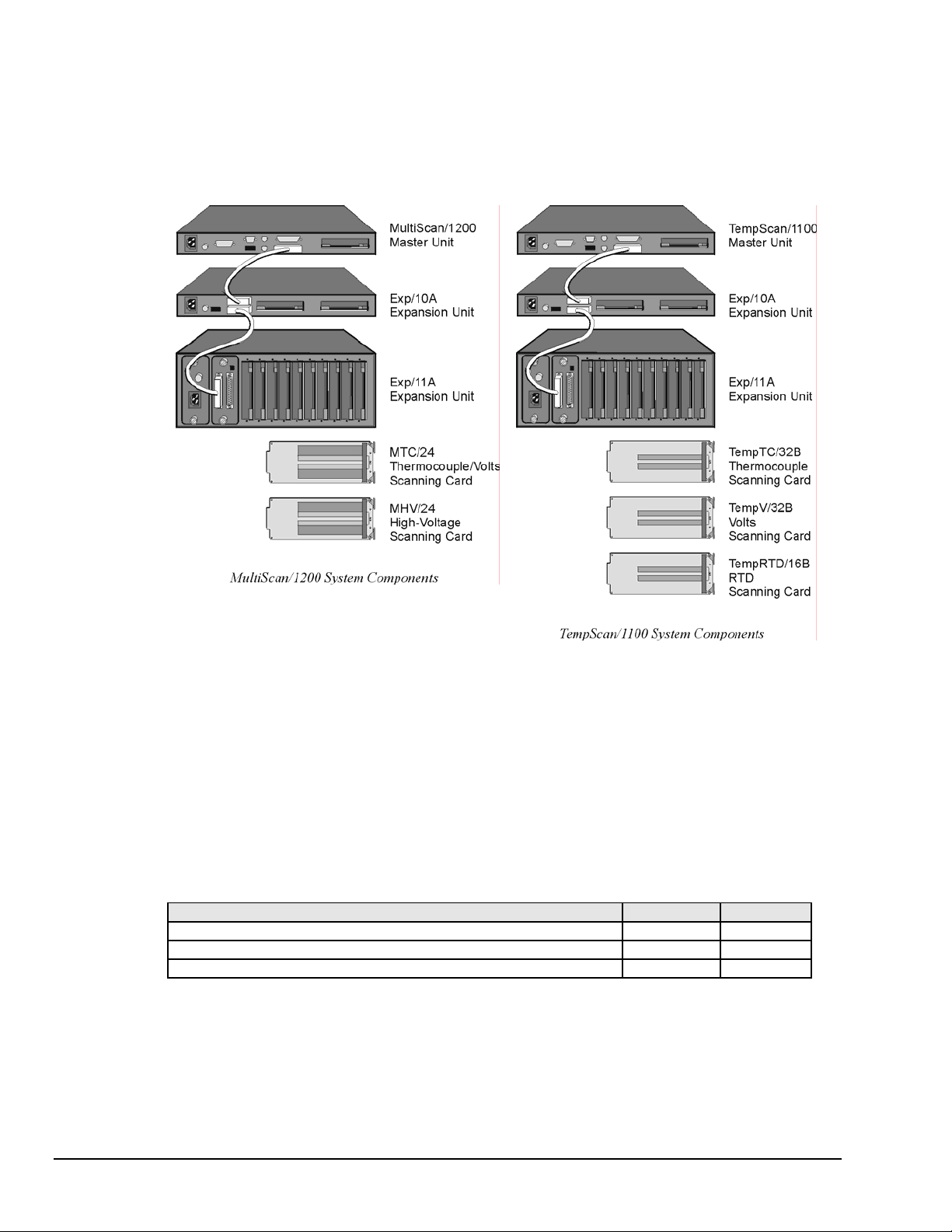
Chapter 1 - System Overview provides a detailed discussion of TempScan/1100 and MultiScan/1200,
Chapter 2 – Expansion Units provides a detailed discussion of the two-slot expansion unit, Exp/10A
Chapter 3 – Scanning Cards discusses the three scanning card options available to the TempScan/1100
Chapter 4 - System Configuration discusses TempScan/1100 or MultiScan/1200 memory allocation, the
Chapter 5 - System Operation discusses how the TempScan/1100 or MultiScan/1200 system operates.
manual begins with a copy of the installation guide that is shipped with those products. Use the
guide to install the associated software, product support, and hardware.
their features, front and rear panel descriptions, and necessary hardware configurations. Both IEEE
488 and RS-232 interfaces are covered. Also provides detailed instructions on line-voltage selection
and fuse replacement, rack-mount and bench-top installation, as well as power-up activation.
Expansion Unit and the ten-slot expansion unit, Exp/11A Expansion Unit. This chapter covers, their
features, front and rear panel descriptions, and necessary hardware configurations.
unit: The TempTC/32B thermocouple scanning card, the TempV/32B volts scanning card, and the
TempRTD/16B RTD scanning card. It also discusses the two scanning card options available to the
MultiScan/1200 unit: The MTC/24 thermocouple/volt scanning card and the MHV/24 high-voltage
scanning card.
required configuration of channels, scans, acquisitions, and triggers, as well as the additional
configuration of alarms, data format, and power-up.
This includes the operation of the acquisition buffer, the digital input/output, the High/Low/Last
(HLL) Registers, the Status and Event Reporting Registers, as well as the channels.
Chapter 6 - System Calibration states how to access ChartView’s built-in automated calibration feature
and also discusses the manual calibration for the TempScan/1100 and MultiScan/1200 units, and for
their respective scanning cards.
Software
Appendices
ChartView discusses the ready-to-use Windows-based data-logging software that features a strip-chart
style graphical interface. The various windows, toolbar buttons and menu items are described and
explained.
ViewXL discusses the ViewXL Microsoft Excel Add-In. The application provides setup and data
acquisition for personal computers running 32-bit versions of Windows. The features of Excel and
ChartView combine seamlessly to form a powerful data acquisition tool.
Appendix A - API Command Reference discusses the entire command set covering both the
TempScan/1100 and MultiScan/1200 units. The command syntax, interpretation, and reference are
provided. The description format of the individual API commands includes the command type,
execution, syntax, description, and an example program excerpt.
Appendix B – IEEE 488, Serial, and ASCII - This appendix provides background information
concerning the IEEE 488 bus, the serial bus, and ASCII controls.
Appendix C - Program Examples in Quick Basic. This appendix is included as a reference for those
individuals who are interested in writing their own programs for use with MultiScan/1200 and/or
TempScan/1100.
Information which may have changed since the time of printing will be found in a
disk, or in an addendum to the manual.
TempScan / MultiScan User’s Manual 879596 v
README.TXT file on
Page 6

vi TempScan / MultiScan User’s Manual
Page 7

Table of Contents
TempScan/MultiScan Quick Start Guide
(p/n 446-0940)
1 - System Overview
Introduction ...... 1-1
TempScan/1100 ...... 1-1
MultiScan/1200 ...... 1-1
Front Panel Indicators ...... 1-2
Rear Panel Switches & Connectors ...... 1-3
TempScan/1100 & MultiScan/1200
Specifications ...... 1-4
Hardware Configuration ...... 1-7
IEEE 488 Configuration ...... 1-8
RS-232/422 Serial Configuration ...... 1-9
Calibration Protection Configuration ...... 1-13
Digital I/O Configuration ...... 1-13
TTL Output & Trigger Input
Configuration ...... 1-14
Expanded Memory Configuration ...... 1-15
Scanning Card & Channel Expansion ...... 1-16
Power Line & Fuse Configuration ...... 1-17
Introduction ...... 1-17
Line Voltage Selection ...... 1-18
Fuse Replacement ...... 1-20
Rack-Mount & Bench-Top Assembly ...... 1-21
Rack Mount ...... 1-21
Bench Top ...... 1-21
Power-Up Activation ...... 1-22
2 – Expansion Units
Exp/10A Expansion Unit ...... 2-1
Introduction ...... 2-1
Front Panel Indicators ...... 2-1
Rear Panel Switches & Connectors ...... 2-2
Exp/10A Specifications ...... 2-3
Exp/10A Hardware Configuration ...... 2-4
Master/Slave Connection ...... 2-4
Slave Configuration ...... 2-5
Channel Assignment ...... 2-5
Exp/11A Expansion Unit ...... 2-7
Introduction ...... 2-7
Front Panel Indicators ...... 2-7
Rear Panel Switches & Connectors ...... 2-7
Exp/11A Specifications ...... 2-8
Exp/11A Hardware Configuration ...... 2-9
Master/Slave Connection ...... 2-9
Slave Configuration ...... 2-10
3 – Scanning Cards
TempScan Scanning Cards ...... 3-1
TempTC/32B Thermocouple Scanning
Card ...... 3-2
TempV/32B Voltage Scanning Card ...... 3-4
TempRTD/16B RTD Scanning Card ...... 3-6
MultiScan Scanning Cards ...... 3-7
MTC/24 Thermocouple/Volt Scanning
Card ...... 3-8
MHV/24 High-Voltage Scanning Card ...... 3-10
4 – System Configuration
Introduction …… 4-1
Memory Allocation …… 4-2
Measuring Modes
(MultiScan/1200 Only) …… 4-2
Line-Cycle Integration / High-Speed Multi-
Channel Mode …… 4-3
Single-Channel High-Speed Burst Mode …… 4-5
Required Configuration …… 4-6
Channel Configuration …… 4-7
Scan Configuration …… 4-9
Acquisition Configuration …… 4-13
Trigger Configuration …… 4-16
Additional Configuration …… 4-18
Alarm Configuration …… 4-19
Stamp Configuration …… 4-22
Data Format Configuration …… 4-26
Power-Up Configuration …… 4-32
TempScan / MultiScan User's Manual vii
Page 8

5 – System Operation
Acquisition Buffer …… 5-1
Buffer Organization …… 5-2
Buffer Query Operation …… 5-4
Buffer Read Operations …… 5-5
Buffer Overrun …… 5-11
High/Low/Last (HLL) Registers …… 5-13
Contents of the HLL Registers …… 5-13
Access to the HLL Registers …… 5-14
Comparing Buffered Data to HLL Data …… 5-18
Status-Reporting & Mask Registers …… 5-18
Theory of Operation …… 5-21
Status-Reporting Registers …… 5-21
Mask Registers …… 5-28
Using Status-Reporting Registers …… 5-28
Additional Operation …… 5-28
Trigger Latency …… 5-28
Real-Time Clock …… 5-28
Open Thermocouple & Range Error
Checking …… 5-28
Software Digital Filtering
(TempScan/1100 Only) …… 5-28
6 – System Calibration
Manual Calibration and
Software-Automated Calibration …… 6-1
Calibration Setup …… 6-2
Calibration Properties …… 6-2
Calibration Protection …… 6-2
Calibration Status …… 6-3
Calibration Password …… 6-3
Calibration of Master Chassis …… 6-4
Calibration of Scanning Cards …… 6-6
Calibration of Thermocouple Scanning
Cards …… 6-8
Calibration of Voltage Scanning Cards …… 6-12
Calibration of RTD Scanning Cards …… 6-13
Software
ChartView Software Reference
ViewXL
viii TempScan / MultiScan User's Manual
Page 9

Appendix A - API Command Reference
Appendix C – Program Examples
in Quick Basic
Introduction …… A-2
Command Syntax …… A-2
Command Interpretation …… A-3
Command Summary …… A-6
Command Reference …… A-11
Command Description Format …… A-11
The Commands …… A-11
@ - Trigger On Command …… A-12
*B - Flush Acquisition Buffer …… A-13
*C - Clear Channel Configuration …… A-14
*F - Restore Factory Settings …… A-15
*G - Set RTD Gain Calibration Reference … A-16
*K - Change Calibration Keyword …… A-17
*P - Adjust Calibration Card Pots …… A-18
*R - Reset Power-On …… A-19
*S - Set Power-Up Configuration …… A-20
*T - Set Scan Time Stamping …… A-21
*W - Set Software Digital Filtering …… A-22
A - Assign Alarm Output …… A-23
A# - Set Scan Alarm Stamping …… A-24
C - Configure Channels …… A-25
C# - Select Cards …… A-28
D# - Set Relay Make Time …… A-29
E - End Calibration Mode …… A-30
E? - Query Error Status …… A-31
F - Set Data Format …… A-32
F# - Set Burst Mode Frequency …… A-34
G - Calibrate Channel Gain …… A-35
H - Calibrate Channel Offset …… A-36
I - Set Scan Interval …… A-37
I# - Set Digital Input Stamping …… A-38
J - Calibrate Cold Junction Offset …… A-39
K - Enter Calibration Mode …… A-40
L - Set Trigger Level …… A-41
L# - Set Scan Rate …… A-42
M - Set SRQ Mask …… A-43
M# - Set Measuring Mode …… A-44
N - Set Event Mask …… A-45
O - Set Digital Output …… A-46
P - Program Trigger Times …… A-47
Q - Set Query Terminator …… A-48
QC? - Query Card Data …… A-49
R - Read Buffered Data …… A-50
R# - Read Last Readings …… A-51
S - Set Real-Time Clocks …… A-52
T - Set Trigger Configuration …… A-53
U - User Status …… A-55
V - Set User Terminator …… A-58
W# - Set Averaging Weight …… A-59
X - Execute …… A-60
Y - Set Counts …… A-61
? - Query …… A-62
Introduction …… C-1
Reading HLL Status …… C-3
TempScan/1100 …… C-3
MultiScan/1200 …… C-4
Reading HLL Data from Thermocouple &
Volts Cards …… C-5
TempScan/1100 …… C-5
MultiScan/1200 …… C-6
Acquiring Pre- & Post-Trigger Data at
Different Rates …… C-7
TempScan/1100 …… C-7
MultiScan/1200 …… C-9
Acquiring Pre- & Post-Trigger Data at the
Same Rate …… C-11
TempScan/1100 …… C-11
MultiScan/1200 …… C-13
Operating Alarms …… C-15
TempScan/1100 …… C-15
MultiScan/1200 …… C-17
Using the IEEE 488 SRQ with
Alarms …… C-19
TempScan/1100 …… C-19
MultiScan/1200 …… C-21
Acquiring Buffer Data in Binary
Format …… C-23
TempScan/1100 …… C-23
MultiScan/1200 …… C-25
Acquiring HLL Data in Binary
Format …… C-27
TempScan/1100 …… C-27
MultiScan/1200 …… C-29
Using Auto Re-arm to Capture Multiple
Trigger Blocks …… C-31
TempScan/1100 …… C-31
MultiScan/1200 …… C-33
Acquiring Burst Mode Data (MultiScan/1200
Only) …… C-35
Appendix B – IEEE488, Serial, and ASCII
IEEE 488 Bus & Serial Bus Lines …… B-1
IEEE 488 Bus Commands …… B-2
ASCII Codes …… B-3
ASCII Code Summary …… B-3
ASCII Code Details …… B-5
Abbreviations …… B-10
TempScan / MultiScan User's Manual ix
Page 10

x TempScan / MultiScan User's Manual
Page 11
TempScan / MultiScan Quick Start Guide
High-Speed Temperature & Voltage Systems
Reference Note: Adobe PDF versions of user manuals will automatically install onto your hard drive as a part of
product support. The default location is in the Programs group, which can be accessed from the Windows Desktop
Start menu. Refer to the PDF documentation for details regarding both hardware and software. Note that PDF
versions of the documents can also be accessed directly from the data acquisition CD via the <View PDFs> button
located on the CD’s opening screen.
Minimum System Requirements
PC system with Pentium® Processor
Windows 2000 or /XP
64 Mbytes RAM
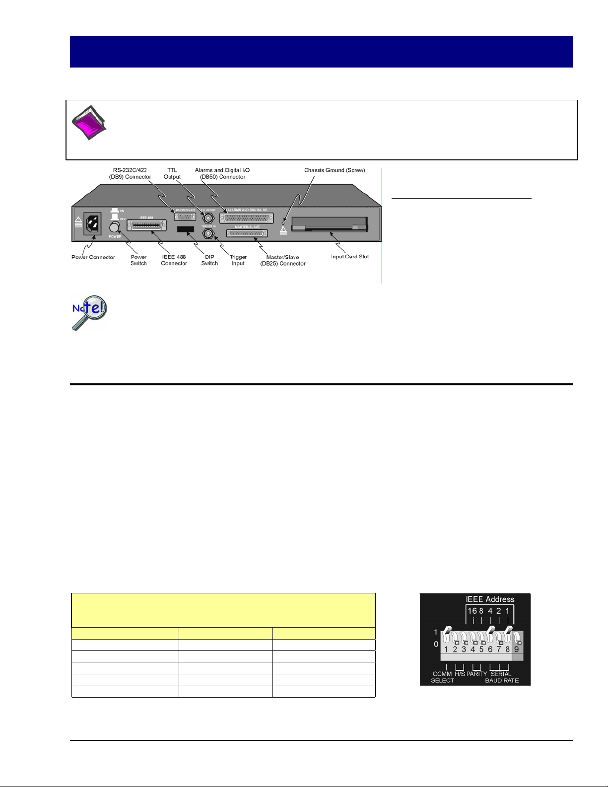
Rear Panel, Applies to both TempScan and MultiScan
o This quick start covers connecting a TempScan/1100 or a MultiScan/1200 to the host computer’s
RS-232 serial port and configuring the device for RS-232 serial operation.
o Because you will be using ChartView, an “out-of-the-box” Windows-based data acquisition program,
no programming is required.
Note: Throughout the remainder of this document the term “scan device” refers to both the TempScan/1100 and to the
MultiScan/1200 data acquisition device.
Hardware Setup
Step 1: Check the Voltage Setting
Based on your order, your scan device was set at the voltage indicated on the sticker located on the rear panel of the unit
(near the power switch): 105-125 or 210-250 volts AC. Verify that the voltage value indicated on the sticker matches the
voltage of your intended AC power supply. If you need to change the AC power line selection for any reason, refer to the
chapter Power & Assembly in your user's manual.
Step 2: Set the Operation Mode via DIP Switch
The scan device is default configured for IEEE 488 port connection to a PC. To configure the unit for RS-232 serial
operation, change the DIP switch setting as indicated in the following table and figure. Otherwise, to configure the unit for
RS-422 serial operation or IEEE 488 operation refer to chapter 1 in your TempScan/1100 & MultiScan/1200 user’s manual.
A PDF version of the manual is included on the data acquisition CD.
The DIP switch is located on the rear panel of your unit. One possible RS-232 serial setting is indicated in the following
figure and table. We make use of this serial setting in this Quick Start Guide. For alternative serial settings, refer to chapter
1 in your TempScan/1100 & MultiScan/1200 user's manual.
DIP Switch Configuration
One of many possible settings for RS-232 Serial Communication*
Selection Micro-switch Setting
COMM SELECT 1 1- RS-232
HANDSHAKE (H/S) 2,3 00 - No Handshake
PARITY 4,5 00 - No Parity
BAUD RATE 6,7,8 101 - 9600 Baud
CALIBRATION 9 0 - Disabled
*Refer to the user’s manual in regard to other configurations.
446-0940, rev 2.2 988892 TempScan / MultiScan Quick Start Guide QS-1
DIP Switch (on Rear Panel)
Set for RS-232 Serial, see table at left.
Page 12
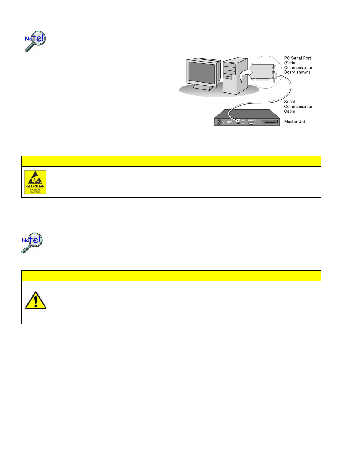
Step 3: Connect the Unit to Your PC
Prior to making a serial connection, make sure that the host PC’s serial (COM) port is available and
properly configured to match the DIP switch setting in Step 2. Do this by navigating from the Windows
Desktop, i. e., Control Panel ⇒ System ⇒ Device Manager tab, then clicking on Ports (COM & LPT).
Use a CA-47 serial communication cable (or equivalent) to
connect the scan device’s RS-232/RS-422 serial port to an
available serial port on your PC.
Note that the single DB9-end of the CA-47 cable connects
to the scan device (referred to as “Master Unit” in the righthand figure).
Note: The PC-end of the CA-47 cable has two connectors,
i.e., one DB9 and one DB25 connector.
Step 4: Connect the Channel Inputs to the Scanning Card
RS-232/RS-422 Serial Communication
Use approved ESD precautions, including static-free work area and grounded wrist strap, when handling
circuit boards and electronic components. Failure to do so could cause equipment damage due to
electrostatic discharge.
Insert the appropriate wires into the selected screw-terminal sockets of your scanning card to make the channel input
connections. Each scanning card contains screw-terminal blocks for making quick input connections. Labeling is provided
on the card for channel identification. Note that tie-wraps can be used in conjunction with the card’s tie-down holes to
provide strain relief and to keep the channel wires organized.
When making differential voltage measurements, you should ensure that one of the common terminal
blocks is connected to the common of the unit being measured.
Step 5: Install the Scanning Card into the Unit
CAUTION
TempScan/1100 scanning cards are designed for and supported only by the TempScan/1100 master unit.
MultiScan/1200 scanning cards are designed for and supported only by the MultiScan/1200 master unit.
Use of a wrong card can cause operating errors and possibly damage equipment.
Do not connect the power to any devices that are connected to the scanning card inputs until after the
scanning cards have been properly installed in the scan device.
1. When the channel input connections on the scanning card are ready, make sure that the POWER pushbutton on the
scan device (TempScan or MultiScan) is in the "OFF" position (extended out).
CAUTION
2. Plug the CA-1 power cable into the unit and then into the proper AC power outlet. Do not connect the power to any
devices that are connected to the scanning card inputs at this time.
3. Install the scanning card into the INPUT CARD slot of the unit.
4. After the scanning card is installed, connect the power lines to the devices that are connected to the scanning card inputs.
Then make other connections as applicable to your system.
Step 6: Apply Power to the System
1. Turn on the host PC.
2. Turn on the scan device (TempScan/1100 or MultiScan/1200) by pushing in the POWER pushbutton.
3. Turn on any applicable devices that are connected to the scanning card inputs.
QS-2 TempScan / MultiScan Quick Start Guide 988892 446-0940, rev 2.2
Page 13
Reference Note:
If the ERROR LED indicator starts flashing, refer to the chapter entitled, Power & Assembly, in your user's
manual. The section includes details regarding possible power-up activation errors. The default location of the
manual and other support documentation is the Program group, accessible from the Windows Desktop Start
menu. Documents can also be accessed directly from the data acquisition CD via the <View PDFs> button
located on the CD’s opening screen.
Software Setup & Startup
Step 1: Install Software and Manuals
1. Remove previous version Scan drivers, if present. You can do this through Microsoft’s Add/Remove Programs feature.
2. Place the Data Acquisition CD into the CD-ROM drive. Wait for PC to auto-run the CD. This may take a few moments,
depending on your PC. If the CD does not auto-run, use the Desktop’s Start/Run/Browse feature to locate and launch the
CD’s setup.exe file.
3. After the intro-screen appears, follow the screen prompts. Upon completing the software installation, continue with
step 2, Start ChartView & Collect Data.
NOTE: Prior to CD 501395D-01, ChartView enhancements were available for purchase. We now provide them at no
additional cost. To enable all ChartView features: (1) From ChartView’s main window, open the File pull-down
menu, (2) select Authorization, (3) enter code C3523DFA6C0A in the dialog box and apply the code.
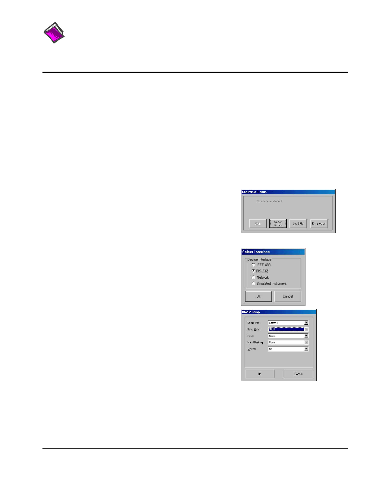
Step 2: Start ChartView & Collect Data
1. Double-click on the ChartView icon, or select the ChartView option from
the ChartView program group. The ChartView Startup dialog box will
appear with three selectable options: Select Device, Load File, and Exit
program. See figure at right.
Click the < Select Device> button. The Select Interface dialog box will
2.
appear. The Select Interface dialog box presents four options:
IEEE 488, RS-232, Network, and Simulated Instrument.
3. Select the RS-232 radio button, then click <OK>.
Note: If using an IEEE 488 or Network interface, refer to the
TempScan/MultiScan User’s Manual (p/n 446-0901). You can access
the manual directly from the data acquisition CD by using the
<View PDFs> button located on the CD’s opening screen.
To practice using ChartView with no instrument connected
select Simulated Instrument as the device interface.
4. When you choose RS-232, the RS-232 Setup dialog box appears.
Information regarding Comm Port, Baud Rate, Parity, Handshaking, and
Modem can be viewed and changed from this box. Make sure that the
information matches the current hardware configuration of the DIP switch
setting. Note that a baud setting of 9600 is recommended.
Note: Make sure that the information in the RS232 Setup box matches
the hardware configuration of the DIP switch.
When the dialog box information is complete, click OK.
At this point, the Chart Setup Wizard dialog box opens.
446-0940, rev 2.2 988892 TempScan / MultiScan Quick Start Guide QS-3
Page 14
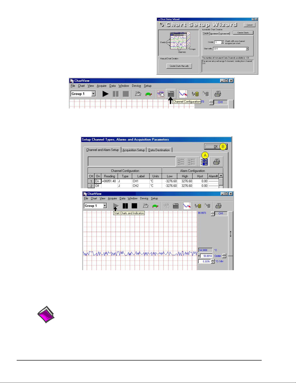
5. In the Automatic Chart Creation portion of the Chart Setup
Wizard box, click the <Create Charts> button. ChartView’s
main window opens. Here we are using the program default
settings. Note that you can go back later and edit the chart setup.
6. In ChartView’s toolbar, click the <Channel Configuration>
button (first figure, following page).
The “Setup Channel Types, Alarms and Acquisition Parameters”
window will open.
7. In the “Setup Channel Types, Alarms and Acquisition Parameters” window (following figure), perform the following
actions: Click the <Turn On/Off Channel Readings> button (item “A”). This activates the Reading column.
Click the <OK> button (item “B”). This accepts the settings. After clicking <OK> the ChartView Main Window will
open.
ChartView Main Window (Partial View)
8. To start the chart scrolling click on the <Start Charts and Indicators> (
click on the <Stop Charts> (
Black Square) button. Feel free to continue exploring ChartView to become more familiar
with the application.
Reference Note:
For detailed information regarding ChartView and the post-acquisition data viewer program,
e.g., PostView, refer to the Adobe PDF version documentation. The default location of the electronic
documents is the Programs group, accessible from the Windows Desktop Start menu.
Documents can also be accessed directly from the data acquisition CD via the <View PDFs>
button on the CD’s opening screen.
Black Triangle) button. To stop the chart scrolling
QS-4 TempScan / MultiScan Quick Start Guide 988892 446-0940, rev 2.2
Page 15

System Overview 1
Introduction ...... 1-1
TempScan/1100 ...... 1-1
MultiScan/1200 ...... 1-1
Front Panel Indicators ...... 1-2
Rear Panel Switches & Connectors ...... 1-3
TempScan/1100 & MultiScan/1200 Specifications ...... 1-4
Hardware Configuration ...... 1-7
IEEE 488 Configuration ...... 1-8
RS-232/422 Serial Configuration ...... 1-9
Calibration Protection Configuration ...... 1-13
Digital I/O Configuration ...... 1-13
TTL Output & Trigger Input Configuration ...... 1-14
Expanded Memory Configuration ...... 1-15
Scanning Card & Channel Expansion ...... 1-16
Power Line & Fuse Configuration ...... 1-17
Introduction ...... 1-17
Line Voltage Selection ...... 1-18
Fuse Replacement ...... 1-20
Rack-Mount & Bench-Top Assembly ...... 1-21
Rack Mount ...... 1-21
Bench Top ...... 1-21
Power-Up Activation ...... 1-22
Introduction
All TempScan/1100 and MultiScan/1200 components are carefully inspected prior to shipment.
When you receive your temperature-and-voltage measurement system, carefully unpack all items from the
shipping carton and check for any damage which may have occurred during shipment. Promptly report the
damage to the shipping agent and your sales representative. Retain all shipping materials in case you must
return the unit to the factory. Refer to the QuickStart Guide at the front of this manual for installation
instructions.
The TempScan/1100 and MultiScan/1200 are high-speed, compact, rack-mountable instruments that
measure up to 992 or 744 channels of temperature or voltage, respectively. Because of their unique
architecture, both instruments offer unrivaled low cost per channel. They connect to a computer via
IEEE 488 or RS-232 interfaces, or via modem, and can be disconnected from the computer for
stand-alone operation.
TempScan/1100
The TempScan/1100 is well-suited for temperature and lower-voltage measurement because its solid-state
scanning provides temperature readings at speeds up to 960 channels per second, an important feature in
applications that require monitoring of tens or hundreds of channels.
MultiScan/1200
The MultiScan/1200 is ideal for temperature and voltage measurements that require channel-to-channel
isolation. The unit provides 500 V of channel-to-channel isolation for voltage, and 200 V of channel-tochannel isolation for thermocouples. The MultiScan/1200 uses relays to provide isolation and to scan
thermocouples and volts at up to 147 channels per second. The unit can also digitize waveforms on
a single channel at up to 20 kHz.
TempScan / MultiScan User’s Manual 899493 System Overview 1-1
Page 16
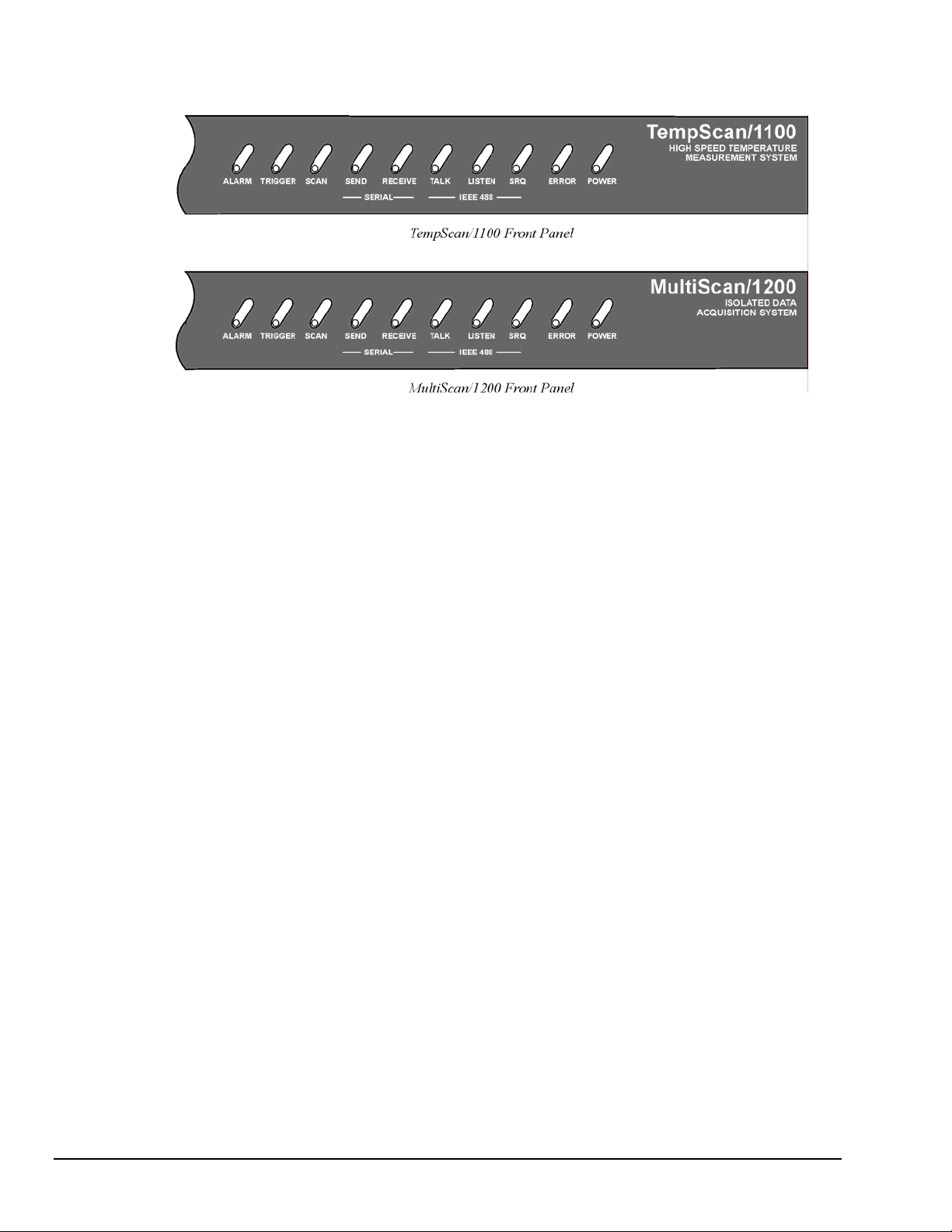
Front Panel Indicators
Ten (10) LED indicators on the front panel of either the TempScan/1100 or MultiScan/1200 display the
status of the temperature-and-voltage measurement system:
ALARM ON when an alarm has occurred. The indicator remains ON until the alarm condition
TRIGGER Flashes when
SCAN ON when the unit is storing a channel scan in its internal buffer.
SEND (For RS-232 operation only) ON when transmitting data to the serial interface.
RECEIVE (For RS-232 operation only) ON when receiving data from the controlling computer.
TALK (For IEEE 488 operation only) ON when the unit is in the Talker state, OFF when the unit
LISTEN (For IEEE 488 operation only) ON when the unit is in the Listener state, OFF when the
SRQ (For IEEE 488 operation only) ON when the unit has generated a Service Request (SRQ),
ERROR ON when an error has occurred, OFF when no error condition exists. For more
POWER ON when power is applied to the unit and the power switch on the back panel is in the ON
clears. OFF when no alarm condition exists.
Armed and waiting for a Trigger; is ON continuously when triggered; is OFF
when data collection is finished. The Trigger is also turned OFF by IEEE
DCL or SDC.
is in the Idle or Listener state.
unit is in the Idle or Talker state.
OFF when no SRQ is pending. For more information, see command Set SRQ Mask (
information, see command Query Error Status (
E?).
position (depressed). OFF if power is not present.
M).
1-2 System Overview 899493 TempScan / MultiScan User's Manual
Page 17
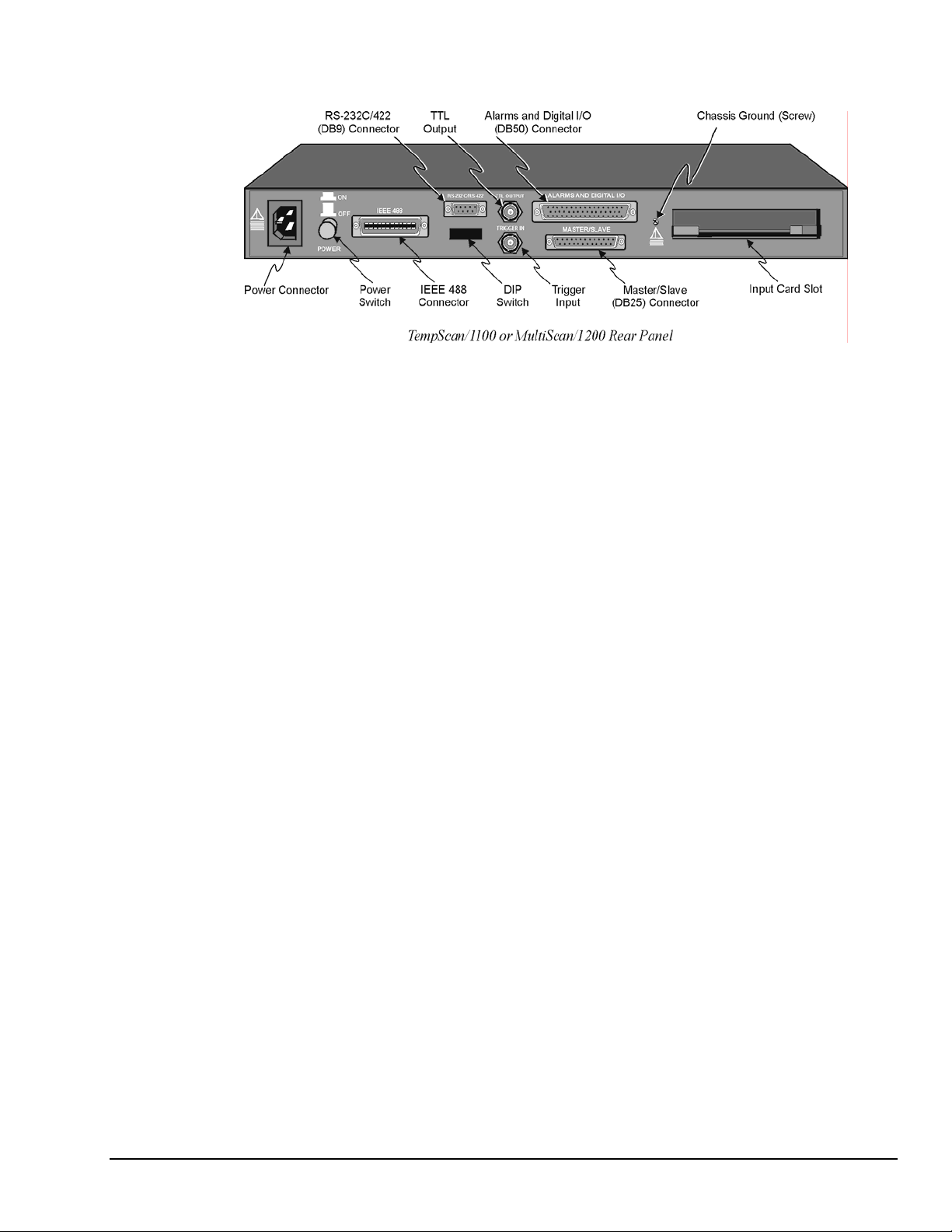
Rear Panel Switches & Connectors
Two (2) switches, seven (7) connectors, one (1) grounding nut, and one (1) input card slot on the rear panel
of either the TempScan/1100 or MultiScan/1200 provide power, IEEE 488 addressing, triggering, a single
point grounding node, and I/O connections.
Power Switch
Used to turn power to the unit ON and OFF. When the switch is in
the depressed position the power is ON. When in the extended
position, the power is OFF.
DIP Switch
For IEEE 488: Used for selecting IEEE 488 communication and bus
address.
For RS-232: Used for selecting RS-232 serial
communication, handshaking, parity and baud rate.
Microswitch 9 is used to enable/disable the hardware
protected portion of NV-RAM.
Power Connector
Provides power for the unit. Internally configurable for either 105125 or 210-250 VAC, 50/60Hz, plus fuse circuit breaker.
IEEE 488 Connector
RS-232C Connector
Port for the IEEE 488 interface.
DB9 serial port for operation at remote distances from controlling
computer supports 300 to 9,600 baud using RTS/CTS or
XON/XOFF handshaking (XON/XOFF for ASCII transmissions
only).
TTL Output Connector
BNC TTL scan output signal occurs for each channel scan; used for
synchronizing other equipment with TempScan/1100 or
MultiScan/1200 acquisition.
Trigger Input Connector
BNC trigger input for starting and/or stopping acquisition of the
TTL output signal.
Alarms & Digital I/O Connector
DB50 port offers easy access to Alarms and Digital I/O
(32 digital outputs and 8 digital inputs)
Master/Slave Connector
DB25 master/slave port connects to Exp/10A and/or Exp/11A
expansion slave units to support applications of up to 992 channels
with the TempScan/1100 master unit, or up to 744 channels with the
MultiScan/1200 master unit.
Grounding Screw
An external single-point grounding node has been supplied for (but
not limited to) thermocouple shield termination.
TempScan / MultiScan User’s Manual 899493 System Overview 1-3
Page 18

TempScan/1100 & MultiScan/1200 Specifications
CAUTION
Note:
Channels
Number of Slots: One (1) slot
Number of Channels (TempScan/1100): Up to 32 differential thermocouple or voltage inputs, or up to
16 RTD inputs; accepts TempTC/32B, TempV/32B, or TempRTD/16B scanning modules
Number of Channels (MultiScan/1200): Up to 24 differential thermocouple or voltage inputs; accepts
MTC/24 or MHV/24 scanning modules.
Channel Attributes: High and low set points; hysteresis values for high and low set points.
Scan Sequence: Any combination of temperature and voltage channels may be scanned, but channels are
scanned in ascending numerical order.
Scan Interval: Absolute time between scans (
Note that specifying a value of 00:00:00.0 results in no delay between channel scans.
Scanning Modes (TempScan/1100): For thermocouples up to 500 feet: 960 channels/sec @ 60 Hz;
800 channels/sec @ 50 Hz; For thermocouples over 500 feet: 240 channels/sec @ 60 Hz,
200 channels/sec @ 50 Hz.
Scanning Modes (MultiScan/1200): For multi-channel scanning: 147 channels/sec @ 50 or 60 Hz;
For 32-point line-cycle averaging enabled: 44 channels/sec @ 60 Hz, 38.5 channels/sec @ 50 Hz;
For single-channel burst mode: 1 channel @ 20K samples/sec.
Please read this manual carefully! If equipment is used in any manner not
specified in this manual, the protection provided by the equipment may be
impaired.
These specifications are subject to change without notice.
hh:mm:ss.s); min = 00:00:00.0, max = 99:59:59.9.
Triggers
Installation Category: For CE: Category 1.
Programmable Triggering: Temperature or Voltage level (above or below), absolute time of day, alarm
condition (on or off), IEEE GET, IEEE TALK, external TTL trigger (rising or falling), specified
number of readings.
Temperature-Level Trigger: Programmable value for any one channel. For MultiScan/1200: This
trigger not available when in single-channel burst mode.
TTL Trigger: Programmable for rising or falling edges.
Pre-Trigger Count: Programmable integer (< memory size -1).
Post-Trigger Count: Programmable integer.
Trigger Input Connector: External BNC connector
Trigger Output Connector: External BNC connector
1-4 System Overview 899493 TempScan / MultiScan User's Manual
Page 19
Data Storage & Format
Storage: 128 K reading (256 Kbyte) standard; optional 500 K reading (1 Mbyte), 2 M reading (4 Mbyte),
4 M reading (8 Mbyte).
Data Formats: ASCII and binary; binary format returns a 16-bit compensated and linearized temperature
value (0.1°C/bit); user-programmable for hi/low byte or low/hi byte. Note that high speed DMA
transfers are binary format only.
Statistical Parameters: High, Low, and Last available per channel. For MultiScan/1200: Not available
when in single-channel burst mode.
Time Stamping: Available for each scan group and for each channel’s high, low, and last parameters.
For MultiScan/1200: Not available when in single-channel burst mode.
Time Format: Absolute Time/Date stamping (
+hh:mm:ss.mil,DDDDDDD) and scan interval timebase (hh:mm:ss.t). For MultiScan/1200: Not
(
hh:mm:ss.mil,MM/DD/YY), relative Time/Date stamping
available when in single-channel burst mode.
Alarm Stamp: Available for each scan group. For MultiScan/1200: Not available when in single-channel
burst mode.
Digital Input Stamp: Available for each scan group. For MultiScan/1200: Not available when in single-
channel burst mode.
IEEE 488 Interface
CAUTION
The IEEE 488 terminal must only be used to control a non-isolated IEEE 488
system. The common mode voltage (cable shell to earth) must be zero.
Interface Use: Digital communication (as opposed to analog) for IEEE 488 compliant computer platforms,
as well as IEEE 488 compliant platform-independent configurations. Messages sent 1 byte (8 bits) at
a time. Supports data rates up to 1 Mbyte/sec. Up to 15 devices can be connected to one bus.
Total bus length up to 20 meters. Allowable cable distance between devices is up to 2 meters.
Message transactions are hardware handshaked.
Installation Category: For CE: Category 1.
Implementation: SH1, AH1, T6, TE4, L4, LE4, SR1, PP0, RL0, DC1, DT1, C0, E1.
Programmable Parameters: Alarm set points, thermocouple type, temperature units, Trigger level,
Pre-Trigger and Post-Trigger scan interval, Trigger mode, SRQ mask, scan count, Pre-Trigger count,
digital input, digital output, real time settings, data output format, and terminators.
Data Transfer Speed: Up to >300 Kbytes/s.
Connector: Standard IEEE 488 connector with metric studs.
RS-232 Serial Interface
CAUTION
The RS-232 terminal is only for connecting devices having signals at serial
communications levels.
Installation Category: For CE: Category 1.
Baud Rates: 300, 600, 1200, 2400, 4800 and 9600.
Data Bits: 8.
Stop Bits: 1.
Parity: Even, Odd, None.
Handshaking: RTS/CTS, XON/XOFF (for ASCII transmissions only).
Connector: Male DB-9.
TempScan / MultiScan User’s Manual 899493 System Overview 1-5
Page 20
Digital I/O Interface & Alarms
Installation Category: For CE: Category 1.
Number of Digital Inputs: 8 bits, TTL level compatible.
Number of Digital Outputs: 32 bits, TTL level compatible. Can be programmed as alarms. Note that the
32 TTL outputs can be set or cleared via program control.
Alarm Conditions: May be detected by SRQ or by software query (SPoll or U command).
Alarm Update Rate: Alarms are updated whenever a channel assigned to an alarm is measured.
Connector: Female DB50 50-pin (32 Alarms, 8 digital inputs, 10 ground pins), mating connector supplied.
General
Installation Category: For CE: Category 2 for Line Voltage Input terminal. All other terminals are
Category 1.
Warm Up: 1 hour to rated accuracy.
Master/Slave Port: Female DB-25.
Chassis Ground Connection: Screw terminal.
Dimensions: 425 mm wide × 305 mm deep × 45 mm high (16.75” × 12” × 1.75”).
Weight: 3.62 kg. (8 lbs.).
Operating Environment: For standard: Indoor use, 0 to 50°C; 0 to 95% RH (non-condensing) to 35°C;
linearly derate 3% RH/°C from 35 to 50°C; For CE: Indoor use at altitudes below 2000 m,
0 to 40°C; 0 to 80% RH up to 31°C decreasing linearly 4% RH/°C to 40°C.
Control Switches: Power Switch, IEEE 488 or RS-232, IEEE address, handshake, parity,
baud rate, calibration memory write enable/disable.
Front Panel Indicators: LED indicators for ALARM, TRIGGER and SCAN; for SEND and RECEIVE
(serial interface); for TALK, LISTEN and SRQ (for IEEE 488 interface); and for ERROR and
POWER.
Power: 105-125 or 210-250 VAC, 50/60 Hz; 20 VA maximum (internal slide switch).
CAUTION
Line Voltage: The protective conductor terminal on the AC line connector must
be connected to an external protective earthing system. Failure to make such a
connection will impair protection from shock.
WARNING
Fuse: 1/2A, 250 V, Slo Blo, 3AG (for 105-125V power line) or 1/4A, 250V, Slo Blo, 3AG (for 210-250V
power line).
Service: This product contains no operator serviceable parts. Service must be
performed by qualified personnel. All terminals, including the AC line and
scanning cards, must be disconnected prior to opening the TempScan/1100 or
MultiScan/1200 case. Internal voltage potentials exist which could cause bodily
injury or death!
CAUTION
Fuse Failure: Fuse failure indicates a possible problem within the device circuitry.
If a fuse blows, contact a qualified service representative. Replacement fuses are
to be installed by qualified service personnel with the unit disconnected from the
power source and with all other terminals disconnected. If the line voltage
selector is changed, then the fuse designated for that line voltage must be used.
1-6 System Overview 899493 TempScan / MultiScan User's Manual
Page 21

Calibration
Calibration of cold junction sensor: Software control of calibrated thermocouple using ChartView’s
built-in calibration feature. The automated calibration function is accessed from ChartView’ Device
pull-down menu using “Select Status” and then selecting “Calibration.” Note that calibration is
performed for each card and chassis in the system.
Voltage Calibration: Software control of gain and offset.
Calibration Constants: Chassis constants stored in NV-RAM. Card constants stored in card’s on-board
EEPROM.
Hardware Configuration
The TempScan/1100 or MultiScan/1200 unit is equipped with a high-speed IEEE 488 interface and an
RS-232 interface. Its IEEE 488 interface is useful in laboratory applications and enables real-time transfers
of acquired data to the host computer’s hard drive for inexpensive mass storage.
Its RS-232 interface is ideal in applications that require the placement of instrumentation at remote
distances from the controlling computer, such as process and environmental control.
This unit can be set up with an IEEE 488 or a RS-232 interface configuration, as determined by the DIP
switch accessible from the rear panel. This DIP switch via its nine microswitches select which command
set is to be used – IEEE 488 or RS-232 – and the operating parameters for each.
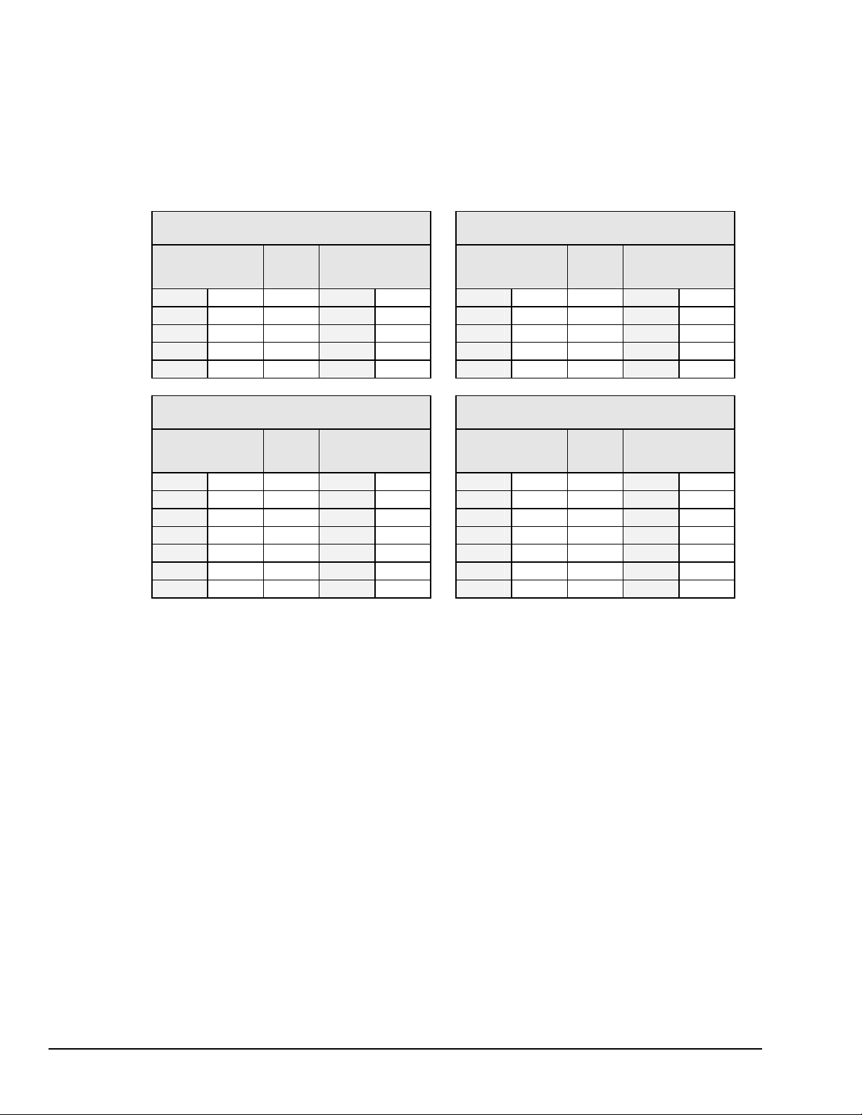
The table shows the options for its nine microswitches. Additional DIP switch settings are shown in the
following sections.
Micro- Label Setting Description
switch #
2,3
4,5
6,7,8
Note:
COMM SELECT 0 IEEE 488 (N/A)
1
1 (N/A) RS-232
HANDSHAKE (H/S) 00 No Handshake No Handshake
01 Software Handshake only
10 Hardware Handshake only
11
IEEE ADDRESS or 00 Decimal value 0 No Parity
PARITY 01 Decimal value 8 Odd Parity
10 Decimal value 16 Even Parity
11 Decimal value 24 (N/A)
IEEE ADDRESS or 000 Decimal value 0 300 baud
BAUD RATE 001 Decimal value 1 600 baud
010 Decimal value 2 1200 baud
011 Decimal value 3 2400 baud
100 Decimal value 4 4800 baud
101 Decimal value 5 9600 baud (See Note)
110 Decimal value 6 (N/A)
111 Decimal value 7 (N/A)
CHASSIS 0 Disabled Disabled
9
CALIBRATION
ENABLE
(1) XON/XOFF handshaking is valid for ASCII transmissions only. (2) At 9600 baud,
hardware (RTS/CTS) handshaking and possibly software (XON/XOFF) handshaking may be
required to maintain serial performance.
Rear Panel DIP Switch
IEEE 488 RS-232
(XON/XOFF) (See Note)
(RTS/CTS)
Both Hardware and Software
1 Enabled Enabled
Handshake
Software Handshake only
(XON/XOFF) (See Note)
Hardware Handshake only
(RTS/CTS)
Both Hardware and Software
Handshake
TempScan / MultiScan User’s Manual 899493 System Overview 1-7
Page 22

The rear panel DIP switch is read only during power-on or reset and should be set before applying power.
To modify any of these defaults, change the microswitch settings using a small screwdriver. The enclosure
does not need to be opened to change these settings.
IEEE 488 Configuration
One way in which the TempScan/1100 or MultiScan/1200 unit can be controlled, is through its IEEE 488
port connector. Consequently, when configured as an IEEE 488 bus device, the unit must have an IEEE
488 bus address.
DIP Switch
For IEEE 488 operation, the single microswitch labeled COMM SELECT should be down (0) on the rear
panel DIP switch . This down (0) position is the factory default. The up (1) position is reserved for
RS-232 serial communication. When IEEE 488 operation is enabled, the five microswitches labeled
IEEE ADDRESS are used to configure the required IEEE 488 bus address.
The bus address can be set from 0 through 30 and is read only at power-on or reset. The address is selected
by simple binary weighting. The switch labeled 1 is the least significant bit (LSB); 16 is the most
significant bit (MSB). The factory default is bus address 7. Note that if address 31 is selected, it defaults
to address 30 because the IEEE 488 standard has reserved address 31.
The rear panel DIP switch is read only during power-on or reset and should be set before applying power.
To modify any of these defaults, change the microswitch settings using a small screwdriver. The enclosure
does not need to be opened to change these settings.
1-8 System Overview 899493 TempScan / MultiScan User's Manual
Page 23
RS-232/RS-422 Serial Configuration
Alternatively, the TempScan/1100 or MultiScan/1200 unit can be controlled through its serial port
connector. Complete serial port configuration is accomplished by using both internal jumpers and DIP
switch settings. The internal jumpers, located on the main board behind each serial connector, are used to
configure the port with either RS-232 or RS-422 electrical characteristics. The DIP switch, located on the
rear panel, is used to determine handshaking, parity, and baud rate. Furthermore, the selection of an
RS-232 or RS-422 electrical configuration determines the serial port pattern of pin connector signals, as
discussed later.
Internal Jumpers
The jumpers within the unit configure the serial port electrically as either RS-232 or RS-422. To change
the serial port configuration, it is necessary to perform the following steps:
Never disassemble the case while it is connected to the AC power line!
Internal voltage potentials exist which could cause bodily injury or death!
Never disconnect the AC power line from the TempScan/1100 or MultiScan/1200
while its scanning cards are connected to an external device! Common mode
voltage potentials exceeding 60 VDC or 30 Vrms at the terminals, may exist which
could cause bodily injury or death!
WARNING
WARNING
Note:
If disassembly or disconnections are necessary, first turn off the power, then disconnect the
scanning cards, next disconnect the AC power line, and then any other cables, prior to unit
disassembly.
To Change the Serial Configuration
1. Turn off the power, disconnect the scanning cards, the power line cord, then all other cables from the
unit. For more information, see section Disconnecting & Reconnecting the System During Setup on
page 1-6.
2. Place the unit on a flat surface. Remove the six screws on top of the case. Remove the top cover.
3. The serial port is capable of operating in RS-232 or RS-422 mode. This selection is done via a set of
hardware jumpers located on the main board behind the serial connector. A 12-position jumper plug
must be inserted in one of the two available positions for proper operation (across JP11 and JP12 for
RS-232, across JP12 and JP13 for RS-422). These jumpers are factory set for RS-232 as shown in the
figure. To reconfigure the serial port for RS-422 operation, remove the jumper plug and reinsert it
into the lower 2 rows of jumpers.
TempScan / MultiScan User’s Manual 899493 System Overview 1-9
Page 24
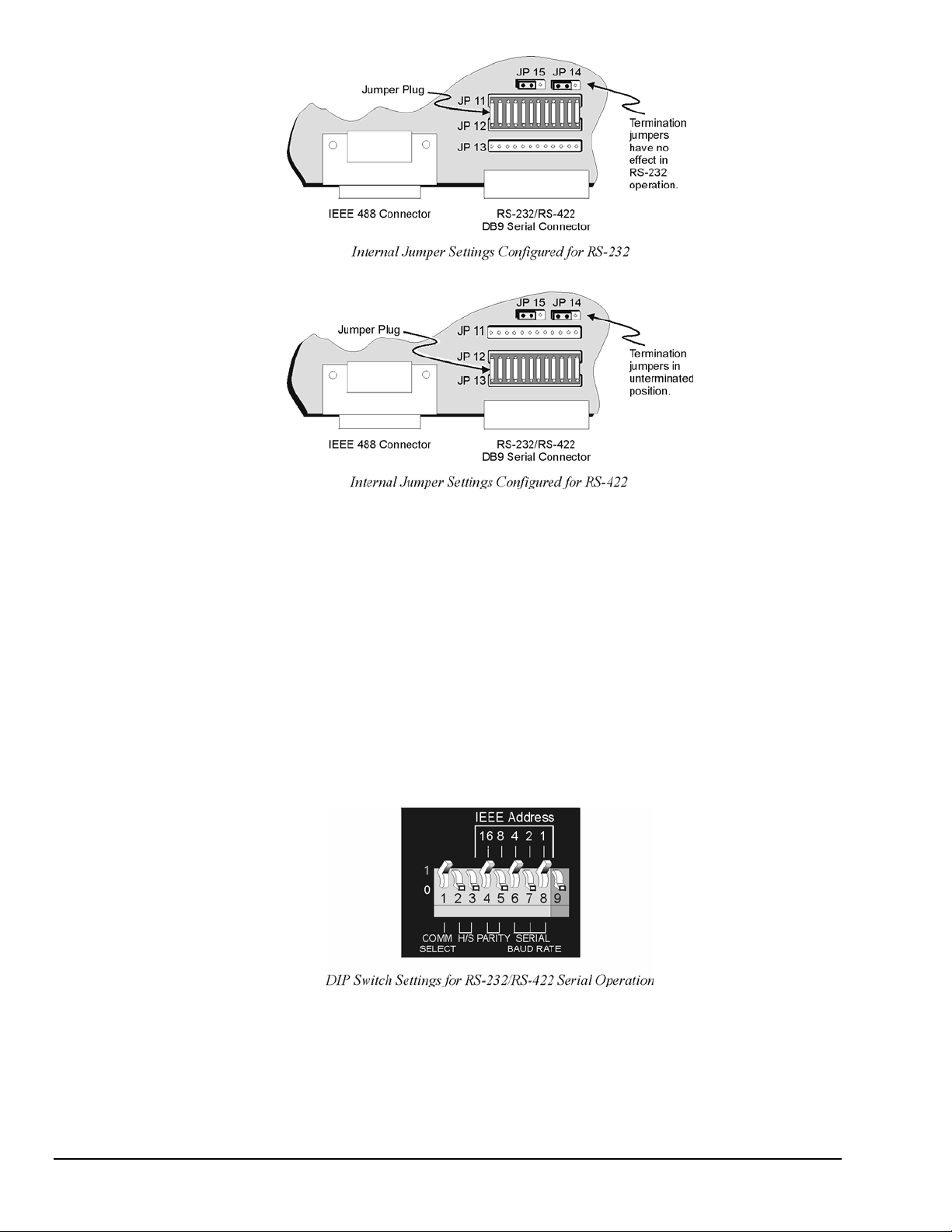
4. If configured for RS-422, the port’s Receive Data (RxD+) and Clear to Send (CTS+) input lines may
optionally be terminated with a 100-Ohm resistor. Termination resistors are selected by positioning
the two flea clips (labelled JP14 and JP15). These jumpers are factory set to the unterminated
position,
as indicated in the previous figures. Note that when using RS-422 in a single-ended configuration,
ports must be unterminated. Termination jumpers have no effect when the port is configured for
RS-232 operation.
5. Once the jumper(s) have been repositioned for your application, make note of the new jumper settings
for later reference.
6. Carefully reassemble the unit.
Note:
For re-assembly, first reconnect the AC power line (with the power OFF), next reconnect the
scanning cards, and then any other cables, prior to reapplying power to the entire system.
DIP Switch
To configure the TempScan/1100 or MultiScan/1200 for RS-232/RS-422 serial operation, the single
microswitch labeled COMM SELECT must be up (1) on the rear panel DIP switch. The down (0) position
is reserved for IEEE 488 communication. When serial operation is enabled, additional DIP microswitches
configure the following required parameters: Handshaking, parity, and baud rate.
1-10 System Overview 899493 TempScan / MultiScan User's Manual
Page 25
Handshaking. When the RS-232 port is used, the type of handshaking must be selected by the two
microswitches labeled H/S. The options available are: No handshaking, XON/XOFF, RTS/CTS or both
XON/XOFF and RTS/CTS handshaking. Note that XON/XOFF handshaking is valid for ASCII
transmissions only, and for RS-422 operation with a Macintosh, RTS/CTS handshaking is not
recommended.
Parity. The parity must be selected using the two microswitches labeled PARITY. The options provided
are: No parity, odd parity or even parity.
Baud rate. The baud rate is selected using the three microswitches labeled SERIAL BAUD RATE.
The available baud rates are 300, 600, 1200, 2400, 4800, and 9600.
Note:
(1) XON/XOFF handshaking is valid for ASCII transmissions only. (2) At 9600 baud,
hardware (RTS/CTS) handshaking and possibly software (XON/XOFF) handshaking may be
required to maintain serial performance. However, for RS-422 operation with a Macintosh,
RTS/CTS handshaking is not recommended.
The rear panel DIP switch is read only during power-on or reset and should be set before applying power.
To modify any of these defaults, change the microswitch settings using a small screwdriver. The enclosure
does not need to be opened to change these settings.
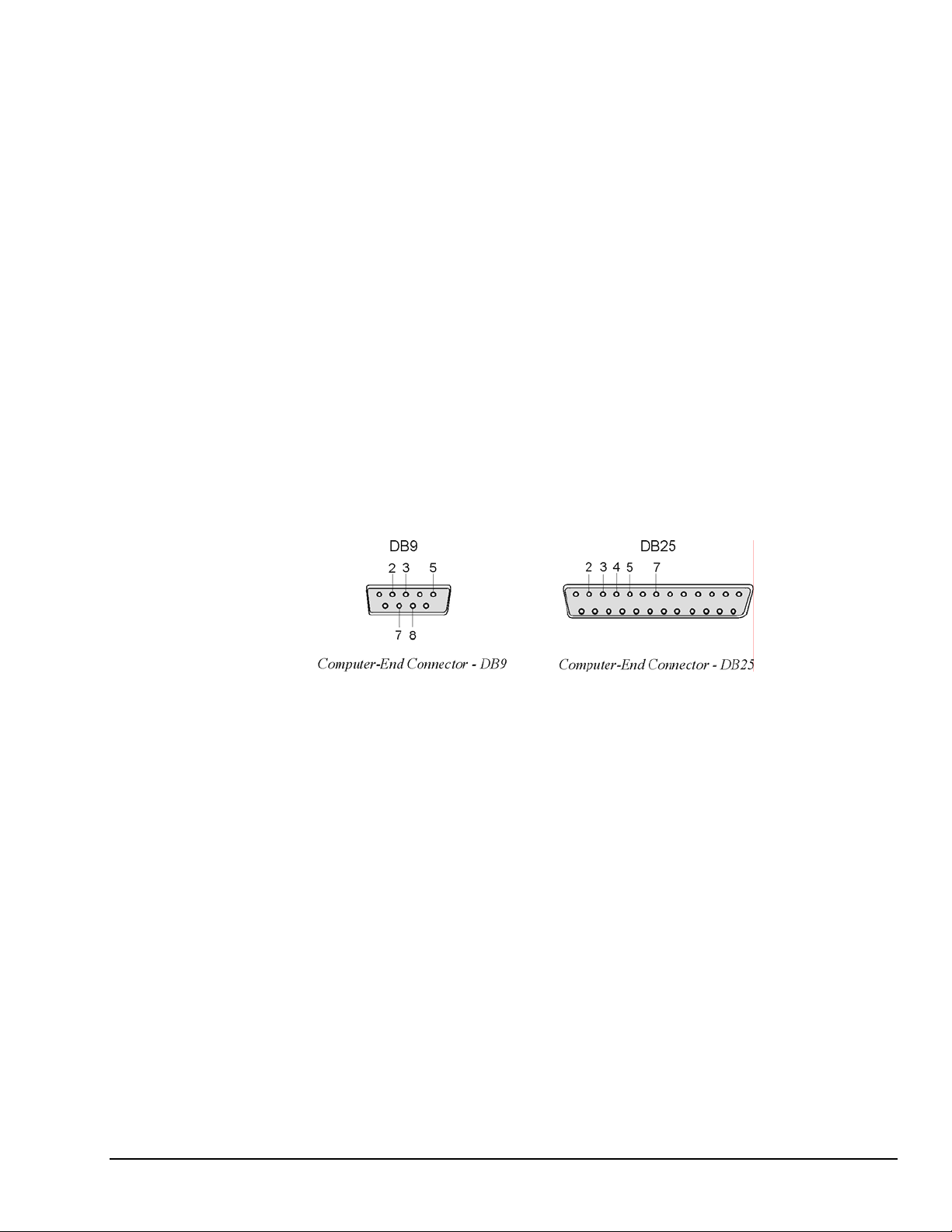
Serial Connector Pins
The TempScan/1100 or MultiScan/1200 unit is equipped with one DB-9S serial connector on its rear panel
and requires a DB-9P mating connector. This connector is configured as an IBM PC when RS-232 levels
are selected, and as a Macintosh when RS-422 levels are selected.
TempScan / MultiScan User’s Manual 899493 System Overview 1-11
Page 26
A CA-47 cable connects the unit with the computer. The TempScan/1100 or MultiScan/1200 end has one
DB9 connector, and the computer end has two connectors – one for a DB9 and one for a DB25. O
ther crossover-type cables can be used if they are wired as shown in the tables. The tables list the
following four connections from the TempScan/1100 or MultiScan/1200 unit:
• To a DB9 connector configured for RS-232
• To a DB25 connector configured for RS-232
• To a DB9 connector configured for RS-422
• To a Mini DIN8 connector configured for RS-422.
TempScan/1100 or MultiScan/1200
To PC Connection (RS-232)
DB9 Male
Pin & Signal
2 RxD-
3 TxD-
5 GND
7 RTS+
8 CTS+
Cable
Wirin
g
←--
--→
←→
--→
←--
DB9 Female
Pin & Signal
3 TxD- 2 RxD-
2 RxD- 3 TxD-
5 GND 5 GND
8 CTS+ 7 RTS+
7 RTS+ 8 CTS+
TempScan/1100 or MultiScan/1200
To PC Connection (RS-232)
DB9 Male
Pin & Signal
Cable
Wirin
g
←--
--→
←→
--→
←--
DB25 Female
Pin & Signal
2 TxD-
3 RxD-
7 GND
5 CTS+
4 RTS+
TempScan/1100 or MultiScan/1200
To Macintosh Connection (RS-422)
DB9 Male
Pin & Signal
1 GND
2 RTS+
4 TxD+
5 TxD-
6 CTS+
8 RxD+
9 RxD-
Cable
Wirin
g
←→
--→
--→
--→
←--
←--
←--
DB9 Male
Pin & Signal
3 GND 1 GND
7 CTS+ 2 RTS+
8 RxD+ 4 TxD+
9 RxD- 5 TxD-
6 RTS+ 6 CTS+
4 TxD+ 8 RxD+
5 TxD- 9 RxD-
TempScan/1100 or MultiScan/1200
To Macintosh Connection (RS-422)
DB9 Male
Pin & Signal
Cable
Wirin
g
←→
--→
--→
--→
←--
←--
←--
Mini DIN8 Male
Pin & Signal
4 GND
2 CTS+
8 RxD+
5 RxD-
1 RTS+
6 TxD+
3 TxD-
The following text describes the various pin connector signals:
• Transmit Data Negative (TxD-): This output pin transmits serial data to an RS-232 or RS-422 device.
The serial data received is sent with the word length, baud rate, stop bits, and parity configured for the
particular port. This signal is low true.
• Transmit Data Positive (TxD+): This output pin transmits serial data to an RS-422 device only.
The pin functions identically to TxD- except that its polarity is inverted. This signal is high true.
• Receive Data Negative (RxD-): This input pin accepts serial data sent by an RS-232 or RS-422 device.
The serial data received is expected to match the word length, baud rate, stop bits, and parity
configuration of the particular port. This signal is low true.
• Receive Data Positive (RxD+): This input pin accepts serial data sent by an RS-422 device only.
It functions identically to RxD- except that its polarity is inverted. This signal is high true.
• Request To Send Positive (RTS+): This output pin is used as a hardware handshake line to prevent an
RS-232 or RS-422 device from transmitting serial data to the TempScan/1100 or MultiScan/1200 unit
when it is not able to accept it. When automatic RTS/CTS handshaking is selected, the unit will assert
(high) the RTS+ signal when greater than 4096 memory locations are available in its internal buffers. If
available memory drops below 4096 bytes, the unit unasserts (low) the RTS+ signal.
• Request To Send Negative (RTS-): This output pin is used as a hardware handshake line with an
RS-422 device only. The pin functions identically to RTS+ except that its polarity is inverted. This
signal is low true.
1-12 System Overview 899493 TempScan / MultiScan User's Manual
Page 27
• Clear To Send Positive (CTS+): This input pin is used as a hardware handshake line to prevent the
TempScan/1100 or MultiScan/1200 unit from transmitting serial data to an RS-232 or RS-422 device
when it is not able to accept it. When RTS/CTS handshaking is selected, the unit will not Transmit
Data (TxD+) out while the CTS+ signal is un-asserted (low). When XON/XOFF or no handshaking is
selected, the CTS+ line is ignored.
• Clear To Send Negative (CTS-): This input pin is used as a hardware handshake line with an RS-422
device only. It functions identically to CTS+ except that its polarity is inverted. This signal is low true.
• Ground (GND): This signal sets the ground reference point for the other RS-232/RS-422 input and
output signals.
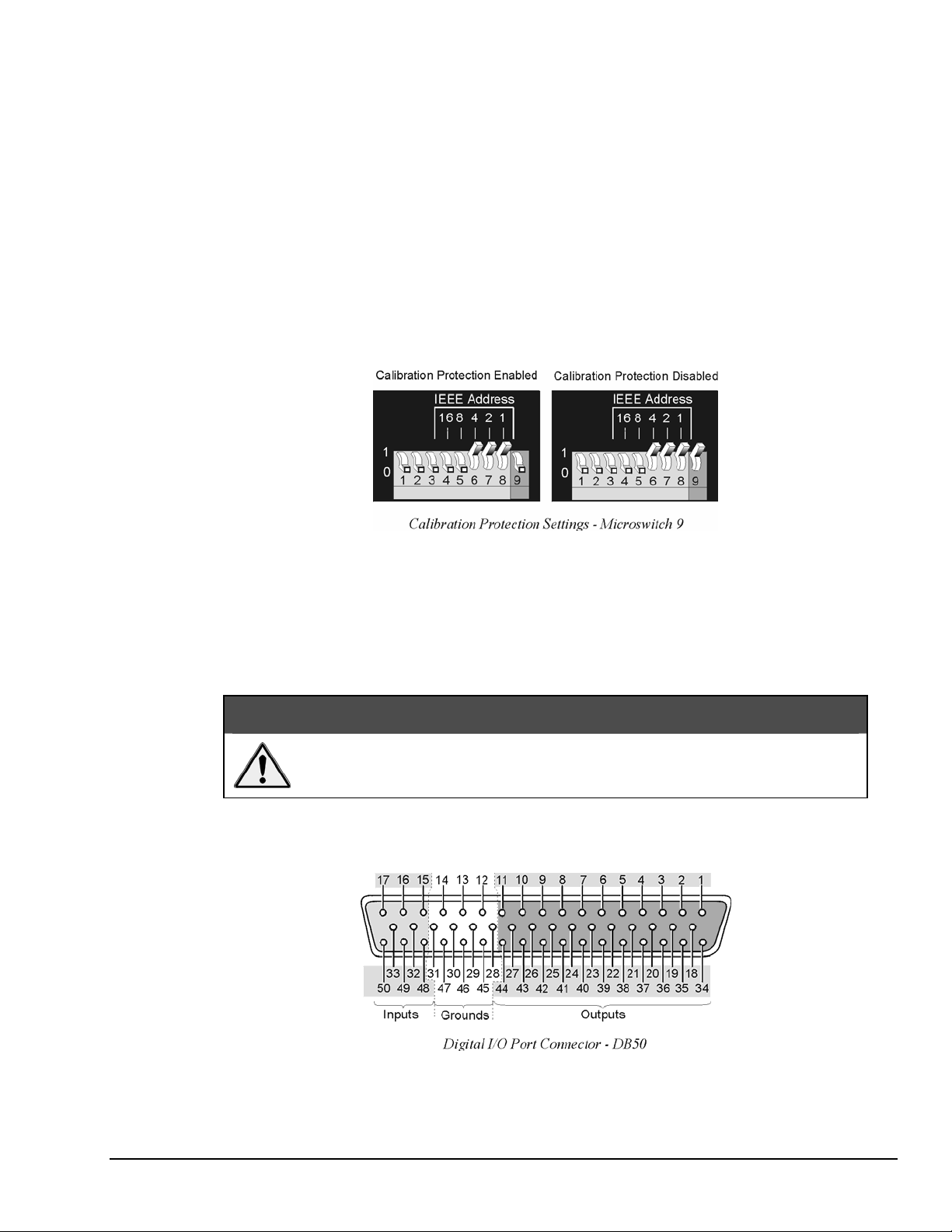
Calibration Protection Configuration
The chassis calibration constants and the calibration password are stored by the TempScan/1100 or
MultiScan/1200 in Non-Volatile RAM (NV-RAM). The password is a safety feature used to prevent
unauthorized personnel from entering calibration mode and altering the calibration constants.
As a safeguard, the calibration password and chassis calibration constants are hardware protected.
This protection is enabled by setting the microswitch 9 to the down (0) position on the rear panel DIP
switch. This is the default factory setting and should remain in this position unless purposely attempting to
change the password or chassis constants.
If it is necessary to change the calibration password (via the
hardware write protection can be disabled by setting microswitch 9 to the up (1) position. For details on
calibration, see chapter System Calibration.
Do not forget to set back the DIP microswitch 9 to the down (0) position when
calibration is complete. Otherwise, the calibration password and calibration
constants may be corrupted and normal operation may be disrupted.
Digital I/O Configuration
*K command) or to recalibrate the chassis, this
CAUTION
Located on the TempScan/1100 or MultiScan/1200 rear panel, the DB50 digital I/O connector provides
eight (8) digital input lines and thirty-two (32) digital output lines. The figure and table locate and describe
the input, output, and ground lines of this connector.
TempScan / MultiScan User’s Manual 899493 System Overview 1-13
Page 28
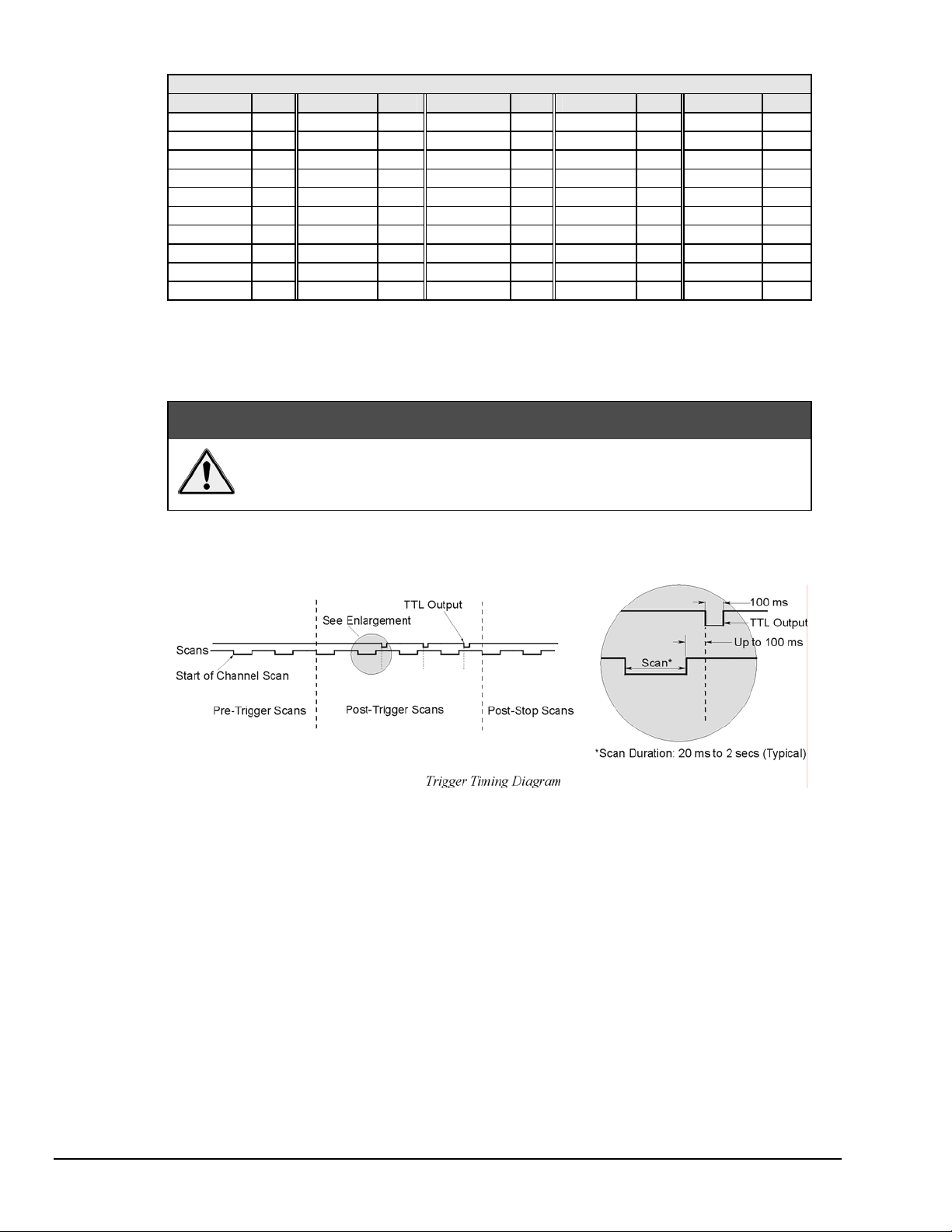
DB50 Digital I/O Pin Descriptions
Line Pin Line Pin Line Pin Line Pin Line Pin
Output 1 1 Output 11 37 Output 21 24 Output 31 11 Ground 12
Output 2 34 Output 12 21 Output 22 8 Output 32 44 Ground 13
Output 3 18 Output 13 5 Output 23 41 Input 1 15 Ground 14
Output 4 2 Output 14 38 Output 24 25 Input 2 48 Ground 28
Output 5 35 Output 15 22 Output 25 9 Input 3 32 Ground 29
Output 6 19 Output 16 6 Output 26 42 Input 4 16 Ground 30
Output 7 3 Output 17 39 Output 27 26 Input 5 49 Ground 31
Output 8 36 Output 18 23 Output 28 10 Input 6 33 Ground 45
Output 9 20 Output 19 7 Output 29 43 Input 7 17 Ground 46
Output 10 4 Output 20 40 Output 30 27 Input 8 50 Ground 47
Each digital output line will drive five (5) standard TTL (transistor-transistor logic) loads. All digital input
lines are one-eighth (0.125) TTL loads. All inputs are protected against damage from high static voltage.
Normal precautions should be taken to limit the input voltages to the range of 0.0 to 5.3 volts. All digital
I/O lines are referenced to digital ground.
CAUTION
Do not exceed the levels described. Otherwise, the TempScan/1100 or
MultiScan/1200 unit may be damaged in a way that is not covered by the
warranty.
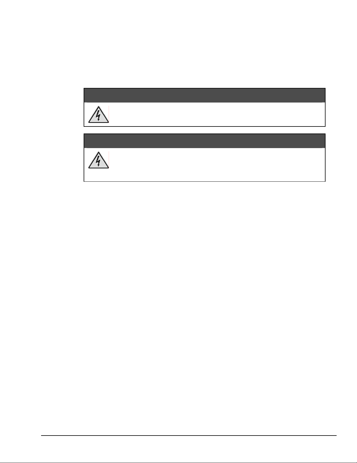
TTL Output & Trigger Input Configuration
The rear panel of the TempScan/1100 or MultiScan/1200 unit also provides two external BNC connectors:
The TTL output and the trigger input. The BNC TTL scan output is used for synchronizing equipment
with TempScan/1100 or MultiScan/1200 acquisition, while the BNC trigger input is used for starting
and/or stopping acquisition of the TTL output. This trigger input can be programmed to activate on a
rising (positive-going) or falling (negative-going) TTL level edge. Any TTL level signal
(> 2.2V = Hi, < 0.8V = Lo) may be used as a trigger pulse. A trigger pulse may also be used to generate a
Service Request. Note that the TTL Out is a LS-TTL compatible output, 0.4 mA sourcing, 8 mA sinking.
When a scan is logged into the acquisition buffer (after the actual scan), the TTL output signal is pulsed for
100 ms. Refer to the timing diagram.
1-14 System Overview 899493 TempScan / MultiScan User's Manual
Page 29
Expanded Memory Configuration
The TempScan/1100 or MultiScan/1200 can accommodate 8 MBytes of memory, which is ideal for both
high-speed and long-term data logging. Measurements can be stored in memory and read out by
a controlling computer as time permits. Readings may be transferred at up to 300 KBytes per second over
the IEEE 488 bus, or up to 9600 baud using the unit’s standard RS-232 port.
To install expanded memory into the unit, it is necessary to perform the following steps:
Never disassemble the case while it is connected to the AC power line!
Internal voltage potentials exist which could cause bodily injury or death!
Never disconnect the AC power line from the TempScan/1100 or MultiScan/1200
while its scanning cards are connected to an external device! Common mode
Note:
voltage potentials exceeding 60 VDC or 30 Vrms at the terminals, may exist which
could cause bodily injury or death!
If disassembly or disconnections are necessary, first turn off the power, then disconnect the
scanning cards, next disconnect the AC power line, and then any other cables, prior to
disassembly.
WARNING
WARNING
To Install Expanded Memory
1. Turn off the power, disconnect the scanning cards, the power line cord, and then all other cables
from the unit.
2. Place the unit on a flat surface. Remove the six screws on top of the case and remove the top cover.
3. Located on the main circuit-board assembly, alongside the scanning card enclosure, are SIMM
memory module slots JP8 and JP7. Remove the 256 KB module from JP7, insert one
4 MB module in its place, and insert the second 4 MB module in JP8.
4. Carefully reassemble the unit, replacing the top cover and screws.
Note:
For re-assembly, first reconnect the AC power line (with the power OFF), next reconnect the
scanning cards, and then any other cables, prior to reapplying power to the entire system.
TempScan / MultiScan User’s Manual 899493 System Overview 1-15
Page 30
Scanning Card & Channel Expansion
Scanning Card Expansion
Each TempScan/1100 or MultiScan/1200 unit can accept one scanning card to provide signal conditioning.
However, if your application demands more channels then you can expand the master unit’s capabilities
with either or both types of expansion units: Exp/10A and/or Exp/11A. Each Exp/10A expansion unit
allows for the addition of two scanning cards, while each Exp/11A expansion unit allows for the addition
of ten scanning cards. Up to fifteen Exp/10A units can be attached to the master unit, giving a maximum
of
30 additional scanning-card slots. Similarly, up to three Exp/11A units can be linked to the master unit,
also giving a maximum of 30 additional scanning-card slots, as shown in the following table.
Expansion Capabilities Exp/10A Exp/11A
Number of expansion scanning-card slots per expansion unit 2 10
Number of identical expansion units that can be linked to the master unit 15 3
Maximum number of expansion scanning-card slots 30 30
Note:
If a combination of Exp/10A and Exp/11A expansion units are linked together, then the
maximum number of expansion scanning-card slots is still 30.
1-16 System Overview 899493 TempScan / MultiScan User's Manual
Page 31

Channel Expansion
The TempScan/1100 system can be expanded up to 992 channels, while the MultiScan/1200 system can be
expanded up to 744 channels. This is easily accomplished via a master/slave architecture wherein a main
or master unit can be connected to as many expansion slave units as allowable within the maximum of
30 scanning cards.
Each Exp/10A or Exp/11A expansion unit has a form factor identical to that of either the TempScan/1100
or MultiScan/1200 master unit, allowing the expansion unit to accept the same scanning cards as its master
unit. When connected to the TempScan/1100, the Exp/10A or Exp/11A is configurable for 32 or 64 input
channels, providing a total expansion capacity of up to 992 channels. When connected to the
MultiScan/1200, the Exp/10A or Exp/11A is configurable for 24 or 48 input channels, providing a total
expansion capacity of up to 744 channels.
An expansion unit can only be controlled by the TempScan/1100 or MultiScan/1200 master unit, and no
digital I/O or alarms are included. However, expansion channels can be programmed to stimulate the
alarms located on the master unit. From the programmer’s perspective, channels are accessed in the same
way as channels in the master unit. When the master unit detects the presence of expansion units during its
power-on sequence, it makes the additional channels available to the programmer. The
U8 command is
available to query the master unit for the total number of channels in the system.
A general description of both types of expansion units, their connections and their configurations,
is discussed in the following chapters.
Power Line & Fuse Configuration
Introduction
The power configuration of any master or expansion unit consists of selecting the line voltage and
replacing the fuses. All of these units – TempScan/1100, MultiScan/1200, Exp/10A, and Exp/11A – each
has a factory default to operate at 105-125 volts AC. However, each unit may be operated at either 105125 or 210-250 VAC.
Do not use this unit outdoors! The unit is intended for indoor use only! Outdoor
conditions could result in equipment failure, bodily injury or death!
Never disassemble the case while it is connected to the AC power line! Internal
voltage potentials exist which could cause bodily injury or death!
Never disconnect the AC power line from the unit while its scanning cards are
connected to an external device! Common mode voltage potentials exceeding 60
VDC or 30 Vrms at the terminals, may exist which could cause bodily injury or
death!
WARNING
WARNING
WARNING
TempScan / MultiScan User’s Manual 899493 System Overview 1-17
Page 32

To change the operating voltage of the TempScan/1100, MultiScan/1200, Exp/10A, and/or Exp/11A unit,
it is necessary to open the enclosure. However, before modifying the voltage, disconnect any input or
output connections from the rear panel of the affected unit and then disconnect the power cord from the
power line terminal.
Line voltage must be set for 105-125 or 210-250 VAC to match the power being supplied to the
TempScan/1100, MultiScan/1200, Exp/10A, and/or Exp/11A unit. If the line voltage is changed, the fuse
must also be changed. Refer to the following text for the line voltage switch and fuse locations.
Line Voltage Selection
As already mentioned, the TempScan/1100, MultiScan/1200, Exp/10A and Exp/11A unit can each operate
with 105-125 or 210-250 VAC, 50-60 Hz power, as set by its internal line-voltage switch (labelled S2 or
SW2). Each unit is shipped from the factory with this operating voltage setting marked on its rear panel.
If this is not the appropriate power setting to be supplied to the unit, then the line voltage and power fuse
must be changed to avoid damage to the unit. The locations of switch S2 or SW2 and the fuse are shown
in the figures. The line-voltage selection procedure is outlined in the following steps.
WARNING
Do not perform the procedures for line voltage selection and fuse replacement,
unless qualified to do so! These procedures are intended to be used by qualified
service personnel only!
WARNING
Never disassemble the unit casing while it is connected to the AC power line!
Internal voltage potentials exist which could cause bodily injury or death!
WARNING
Never disconnect the AC power line from the unit while its scanning cards are
connected to an external device! Common mode voltage potentials exceeding 60
VDC or 30 Vrms at the terminals, may exist which could cause bodily injury or
death!
Note:
If disassembly or disconnections are necessary, first turn off the power, then disconnect the
scanning cards, next disconnect the AC power line, and then any other cables, prior to
disassembly.
To Change the Line-Voltage Selection
1. Turn off the power, disconnect the scanning cards, the power line cord, and then all other cables from
the unit.
2. Place the unit on a flat surface. For the TempScan/1100, MultiScan/1200, and/or Exp/10A: Remove
the six screws on top of the case and remove the top cover. For the Exp/11A: Loosen the two thumb
screws – one at each end – of the power module (left-most panel) and slide out the power module.
3. Located next to the main power supply transformer is the line voltage selection switch (labeled S2 or
SW2). Using a small screwdriver, insert the tip of the screwdriver into the slot of the switch and slide
the switch to the left or right until it "clicks" into place with the desired line voltage selection visible.
1-18 System Overview 899493 TempScan / MultiScan User's Manual
Page 33

CAUTION
It is possible to place the line voltage switch (S2 or SW2) in a partial position
which could cause equipment damage or malfunction. When changing the
position of the line voltage selection switch (S2 or SW2), make sure the switch is
completely positioned to the 115 V or 220 V selection. The switch will “click” into
place when properly positioned.
4. Install a power line fuse appropriate for the line voltage. See section Fuse Replacement – Step 3,
following this section.
CAUTION
Do not use a fuse with a rating higher than specified. Otherwise the unit may be
damaged. If the instrument repeatedly blows fuses, locate and correct the cause of
5. Make note of the new voltage setting for later reference.
6. Carefully reassemble the unit.
Note:
the trouble before replacing the fuse.
For re-assembly, first reconnect the AC power line (with the power OFF), next reconnect the
scanning cards, and then any other cables, prior to reapplying power to the entire system.
TempScan / MultiScan User’s Manual 899493 System Overview 1-19
Page 34

Fuse Replacement
The TempScan/1100, MultiScan/1200, Exp/10A and Exp/11A each contains an internal AC line fuse. This
fuse is located next to the internal line-voltage switch (labelled S2 or SW2). You may replace the fuse by
using the procedures found in the following text.
Note:
WARNING
Never disassemble the unit casing while it is connected to the AC power line!
Internal voltage potentials exist which could cause bodily injury or death!
WARNING
Never disconnect the AC power line from the unit while its scanning cards are
connected to an external device! Common mode voltage potentials exceeding 60
VDC or 30 Vrms at the terminals, may exist which could cause bodily injury or
death!
If disassembly or disconnections are necessary, first turn off the power, then disconnect the
scanning cards, next disconnect the AC power line, and then any other cables, prior to
disassembly.
To Replace the Fuse
1. Turn off the power, disconnect the scanning cards, the power line cord, and then all other cables
from the unit. For more information, see section Disconnecting & Reconnecting the System During
Setup on page 1-6.
2. Place the unit on a flat surface. For the TempScan/1100, MultiScan/1200, and/or Exp/10A: Remove
the six screws on top of the case and remove the top cover. For the Exp/11A: Loosen the two thumb
screws – one at each end – of the power module (leftmost panel) and slide out the power module.
3. Located next to the line-voltage selection switch (labeled S2 or SW2) is the power fuse. Gently pull
upward on the plastic fuse housing. The entire housing with the fuse inside should be removed.
4. Open the fuse housing by pushing up on the tab on the bottom of the housing. Remove the fuse, and
replace it with the proper type using the following list as a guide:
• For line voltage 105-125 V, use fuse type 1/2 A 250 V, Slo Blo, 3AG
• For line voltage 210-250 V, use fuse type 1/4 A 250 V, Slo Blo, 3AG
CAUTION
1. Close the housing. Insert the fuse into the fuse holder.
2. Make note of the new fuse rating for later reference. If you have also changed the operating line-
voltage selection, return to the previous section Line Voltage Selection – Step 5.
3. Carefully reassemble the unit.
Note:
Do not use a fuse with a rating higher than specified. Otherwise the unit may be
damaged. If the instrument repeatedly blows fuses, locate and correct the cause of
the trouble before replacing the fuse.
For re-assembly, first reconnect the AC power line (with the power OFF), next reconnect the
scanning cards, and then any other cables, prior to reapplying power to the entire system.
1-20 System Overview 899493 TempScan / MultiScan User's Manual
Page 35

Rack-Mount & Bench-Top Assembly
The TempScan/1100, MultiScan/1200, Exp/10A and Exp/11A package each includes accessories for rack-mount or benchtop assembly.
Rack Mount
Bench Top
If rack-mount assembly is required, remove the two plastic screws from the pre-drilled holes on each side
of the unit. Since the unit can be mounted with the front or rear panel facing the front of the rack fixture,
remove only those screws from the set of holes that will be toward the front of the rack. Attach the two
rack ears using the enclosed screws.
If bench-top assembly is required, install the self-adhesive rubber feet on the bottom of the unit
approximately one inch from each corner.
TempScan / MultiScan User’s Manual 899493 System Overview 1-21
Page 36

Power-Up Activation
At initial power-up or on the Reset Power-On (*R) command, the TempScan/1100 or MultiScan/1200
performs automatic self-tests to ensure that it is fully functional. The front panel LED indicators show any
errors if they occur. Possible error conditions and their corresponding LED indicator patterns are shown in
the following table. Any LED pattern not shown is an internal error that is not field-serviceable; in this
case, contact the factory. If ERROR is on by itself, there is a configuration error due to setup information
in NV-RAM. Check the error using the Query Error Status (
Error Condition
No Errors
General Hardware Failure
Position-U22 ROM Invalid
Position-U21 ROM Checksum Error
Position-U22 ROM Checksum Error
Non-Volatile RAM Error
Dynamic RAM Error
Interprocessor COM Error
If no problems are found, the POWER LED indicator will remain on while the rest of the indicators will go
out, and the TempScan/1100 or MultiScan/1200 will begin its power-up initialization. This self test is
performed each time the unit is powered up regardless of whether power-on was caused by the power
switch or the Reset Power-On (
steps:
1. Checks for errors at power-up.
2. Checks the flag in the NV-RAM to determine if it should power-up with factory default settings or a
user-defined configuration.
3. Loads appropriate registers with corresponding values in NV-RAM.
4. Checks a flag to see if alarms should be enabled at power-up, and if so, enables them.
5. Loads channel configuration registers.
6. Loads program sequencer with appropriate channel configurations.
7. Resets computations processor to begin acquiring scans.
The self test takes approximately five seconds to complete, after which the TempScan/1100 or
MultiScan/1200 unit is ready for normal operation.
For more information, see section Power-Up Configuration.
E?) command.
LED Indicators
TALK LISTEN SRQ ERROR POWER
(Off) (Off) (Off) (Off) ON
ON
(Off) (Off) (Off) FLASHING ON
(Off) (Off) ON FLASHING ON
(Off) ON (Off) FLASHING ON
ON
ON ON
ON ON ON FLASHING ON
*R) command. During initialization, the self test performs the following
(Off) ON FLASHING ON
(Off) (Off) FLASHING ON
(Off) FLASHING ON
1-22 System Overview 899493 TempScan / MultiScan User's Manual
Page 37

Expansion Units 2
Exp/10A Expansion Unit ...... 2-1
Introduction ...... 2-1
Front Panel Indicators ...... 2-1
Rear Panel Switches & Connectors ...... 2-2
Exp/10A Specifications ...... 2-3
Exp/10A Hardware Configuration ...... 2-4
Master/Slave Connection ...... 2-4
Slave Configuration ...... 2-5
Channel Assignment ...... 2-5
Exp/11A Expansion Unit ...... 2-7
Introduction ...... 2-7
Front Panel Indicators ...... 2-7
Rear Panel Switches & Connectors ...... 2-7
Exp/11A Specifications ...... 2-8
Exp/11A Hardware Configuration ...... 2-9
Master/Slave Connection ...... 2-9
Slave Configuration ...... 2-10
Channel Assignment ...... 2-11
Exp/10A Expansion Unit
Introduction
All Exp/10A components are carefully inspected prior to shipment. When you receive your two-slot
expansion chassis, carefully unpack all items from the shipping carton and check for any damage which may
have occurred during shipment. Promptly report the damage to the shipping agent and your sales
representative. Retain all shipping materials in case you must return the unit to the factory.
Front Panel Indicators
Three (3) LED indicators on the front panel of the Exp/10A display the status of the expansion unit:
• SCAN: ON when the master unit is storing a expansion channel scan in its internal buffer.
• ERROR: ON when an error has occurred, OFF when no error condition exists. For more information,
see command Query Error Status (
• POWER: ON when power is applied to the unit and the power switch on the back panel is in the ON
position (depressed). OFF if power is not present.
E?).
TempScan / MultiScan User's Manual
Expansion Unit 2-1
889897
Page 38

Rear Panel Switches & Connectors
Two (2) switches, three (3) connectors, one (1) grounding nut, and two (2) input card slots on the rear panel
of the Exp/10A provide power, slave addressing, master/slave connections, a single point grounding node,
and scanning card expansion.
• Power Switch: Used to turn power to the Exp/10A ON and OFF. When the switch is in the depressed
position the power is ON. When in the extended position, the power is OFF.
• DIP Switch: Used for selecting the Exp/10A slave address ID.
• Power Connector: Provides power for the unit. Internally configurable for either 105-125 or
210-250 VAC, 50/60Hz, plus fuse circuit breaker.
• Master/Slave Connector: Two DB25 master/slave ports provide one connection to a TempScan/1100,
MultiScan/1200, Exp/10A or Exp/11A unit, and one connection to another Exp/10A or Exp/11A
expansion unit.
• Grounding Screw: An external single-point grounding node has been supplied for (but not limited to)
thermocouple shield termination.
• Shielded Enclosure: For the TempScan/1100: Accepts any combination of TempTC/32B,
TempV/32B, and/or TempRTD/16B scanning cards. For the MultiScan/1200: Accepts any
combination of MTC/24 and/or MHV/24 scanning cards. Note that the TempScan/1100 and
MultiScan/1200 scanning cards must not be mixed within the same system.
2-2 Expansion Units
TempScan / MultiScan User's Manual
889897
Page 39
Exp/10A Specifications
Please read this manual carefully! If equipment is used in any manner not
specified in this manual, the protection provided by the equipment may be
impaired.
Note:
Installation Category: For CE: Category 2 for Line Voltage Input terminal. All other terminals are
Master/Slave Port: Female DB-25 (2)
Number of Slots: Two (2).
Number of Channels (TempScan/1100): Up to 64 differential voltage or thermocouple inputs, or up to 32
Number of Channels (MultiScan/1200): Up to 48 differential voltage or thermocouple inputs;
Channel to System Isolation: 60V peak.
Dimensions: 425mm wide x 305mm deep × 45mm high (16.75” × 12” × 1.75”).
Weight: 2.53 kg. (5.5 lbs.).
Operating Environment: For standard: Indoor use, 0 to 50°C; 0 to 95% RH (non-condensing) to 35°C;
Controls: Power Switch (external), DIP switch for setting slave ID (external).
Front Panel Indicators: LED indicators for SCAN, ERROR, and POWER.
Power: 105-125 or 210-250 VAC, 50/60 Hz; 20 VA maximum.
These specifications are subject to change without notice.
Category 1.
RTD inputs; accepts any combination of two (2) TempTC/32B, TempV/32B or TempRTD/16B
scanning modules.
accepts any combination of two (2) MTC/24 and MHV/24 scanning modules.
linearly derate 3% RH/°C from 35 to 50°C; For CE: Indoor use at altitudes below 2000 m, 0 to
40°°°°C; 0 to 80% RH up to 31°°°°C decreasing linearly 4% RH/°°°°C to 40°°°°C.
CCCCAUTION
AUTION
AUTIONAUTION
CAUTION
CAUTION
CAUTIONCAUTION
Line Voltage: The protective conductor terminal on the AC line connector must
be connected to an external protective earthing system. Failure to make such a
connection will impair protection from shock.
WARNING
WARNING
WARNINGWARNING
Service: This product contains no operator serviceable parts. Service must be
performed by qualified personnel. All terminals, including the AC line and
scanning cards, must be disconnected prior to opening the Exp/10A case.
Internal voltage potentials exist which could cause bodily injury or death!
Fuse: 1/2A, 250 V, Slo Blo, 3AG (for 105-125V power line) or 1/4A, 250V, Slo Blo, 3AG (for 210-250V
power line).
CAUTION
CAUTION
CAUTIONCAUTION
Fuse Failure: Fuse failure indicates a possible problem within the device circuitry.
If a fuse blows, contact a qualified service representative. Replacement fuses are
to be installed by qualified service personnel with the unit disconnected from the
power source and with all other terminals disconnected. If the line voltage selector
is changed, then the fuse designated for that line voltage must be used.
TempScan / MultiScan User's Manual
Expansion Unit 2-3
889897
Page 40

Exp/10A Hardware Configuration
Master/Slave Connection
Up to fifteen Exp/10A expansion units can be connected to the TempScan/1100 or MultiScan/1200 master
unit, giving options of up to 30 expansion scanning cards. Connect the expansion unit as described in the
following steps:
CAUTION
CAUTION
CAUTIONCAUTION
Before connecting an Exp/10A expansion unit to its master unit, or to another
expansion unit, power down all devices that are connected or to be connected.
Failure to do so could damage the equipment.
To Connect the Exp/10A Expansion Unit
1. Turn power off and unplug the master unit and all devices connected to the system.
2. If not already done so, turn power off and unplug the Exp/10A unit(s) which are to be connected.
3. Connect the master/slave cable(s) (CA-35-1) as depicted in the following illustration.
4. Plug in all system devices.
5. Set the slave address on the rear panel DIP switch. See next section Slave Configuration.
6. Turn power on to the master unit.
7. Turn power on to the remaining system devices.
2-4 Expansion Units
TempScan / MultiScan User's Manual
889897
Page 41

Slave Configuration
CAUTION
CAUTION
CAUTIONCAUTION
Avoid linking two or more expansion chassis with the same slave address.
Otherwise, the unspecified addresses may result in operating errors.
For the master/slave configuration to operate correctly, the master unit must either be a TempScan/1100 or
MultiScan/1200; it cannot be an Exp/10A or Exp/11A expansion unit.
Furthermore, each Exp/10A unit must be assigned a unique slave address. Following simple binary
weighting, this slave address is set by using microswitches 5 through 8 of the rear panel DIP switch.
In the following figure, DIP microswitch 8 is in the up position, indicating the default slave address 1.
With all four microswitches 5, 6, 7 and 8 in the up position, this setting indicates a slave address of 15
(8 + 4 + 2 + 1). A maximum of 15 Exp/10A slave addresses can be set, while the address of 0 is not
allowed. The Exp/10A factory default is address 1.
Note:
The address of 0 is not allowed because this is reserved for the master unit address.
Channel Assignment
Channels 1 through 32 are always in the TempScan/1100, and channels 1 through 24 are always in the
MultiScan/1200, while the channels in the Exp/10A expansion unit are treated as extended channels.
With the first Exp/10A slave unit, the first channel in the first scanning card is channel 33 in the
TempScan/1100 system, and channel 25 in the MultiScan/1200 system. With the same slave unit, the first
channel in the second scanning card is channel 65 in the TempScan/1100 system, and channel 49 in the
MultiScan/1200 system. The order of multiple Exp/10A expansion units are set up using the rear panel DIP
switches, as described earlier.
Even if a scanning card slot is left empty in the master unit and/or slave unit(s), the channel assignments
remain the same, as shown in the table. For a 16-channel TempScan/1100 scanning card, the system still
assigns 32 channels to the card slot with the second 16 channels ignored. Likewise, for a 12-channel
MultiScan/1200 scanning card, the system still assigns 24 channels to the card slot with the second 12
channels ignored. For example, if a 16-channel TempRTD/16B scanning module is installed in the first slot
of Logical Unit 2 (the first Exp/10A), then channels 33 through 48 will be assigned and channels 49 through
64 will be ignored.
TempScan / MultiScan User's Manual
Expansion Unit 2-5
889897
Page 42

Exp/10A Slave Address Settings
Microswitches
5 through 8
(0 0 0 0)
0 0 0 1
0 0 1 0
0 0 1 1
0 1 0 0
0 1 0 1
0 1 1 0
0 1 1 1
1 0 0 0
1 0 0 1
1 0 1 0
1 0 1 1
1 1 0 0
1 1 0 1
1 1 1 0
1 1 1 1
2 Inputs 961 – 992 Inputs 721 – 744
Slave
Address
(0) (Master Unit)
1 Slave 1
2 Inputs 65 – 96 Inputs 49 – 72
2 Slave 2
2 Inputs 129 – 160 Inputs 97 – 120
3 Slave 3
2 Inputs 193 – 224 Inputs 145 – 168
4 Slave 4
2 Inputs 257 – 288 Inputs 193 – 216
5 Slave 5
2 Inputs 321 – 352 Inputs 241 – 264
6 Slave 6
2 Inputs 385 – 416 Inputs 289 – 312
7 Slave 7
2 Inputs 449 – 480 Inputs 337 – 360
8 Slave 8
2 Inputs 513 – 544 Inputs 385 – 408
9 Slave 9
2 Inputs 577 – 608 Inputs 433 – 456
10 Slave 10
2 Inputs 641 – 672 Inputs 481 – 504
11 Slave 11
2 Inputs 705 – 736 Inputs 529 – 552
12 Slave 12
2 Inputs 769 – 800 Inputs 577 – 600
13 Slave 13
2 Inputs 833 – 864 Inputs 625 – 648
14 Slave 14
2 Inputs 897 – 928 Inputs 673 – 696
15 Slave 15
Slave Unit
Logical
Unit
(1)
2
3
4
5
6
7
8
9
10
11
12
13
14
15
16
Exp/10A Channel Assignments
Card
Slot
TempScan/1100
Master Unit
(1) (Inputs 1 – 32) (Inputs 1 – 24)
1 Inputs 33 – 64 Inputs 25 – 48
1 Inputs 97 – 128 Inputs 73 – 96
1 Inputs 161 – 192 Inputs 121 – 144
1 Inputs 225 – 256 Inputs 169 – 192
1 Inputs 289 – 320 Inputs 217 – 240
1 Inputs 353 – 384 Inputs 265 – 288
1 Inputs 417 – 448 Inputs 313 – 336
1 Inputs 481 – 512 Inputs 361 – 384
1 Inputs 545 – 576 Inputs 409 – 432
1 Inputs 609 – 640 Inputs 457 – 480
1 Inputs 673 – 704 Inputs 505 – 528
1 Inputs 737 – 768 Inputs 553 – 576
1 Inputs 801 – 832 Inputs 601 – 624
1 Inputs 865 – 896 Inputs 649 – 672
1 Inputs 929 – 960 Inputs 697 – 720
MultiScan/1200
Master Unit
2-6 Expansion Units
TempScan / MultiScan User's Manual
889897
Page 43

Exp/11A Expansion Unit
Introduction
All Exp/11A components are carefully inspected prior to shipment. When you receive your two-slot
expansion chassis, carefully unpack all items from the shipping carton and check for any damage which may
have occurred during shipment. Promptly report the damage to the shipping agent and your sales
representative. Retain all shipping materials in case you must return the unit to the factory.
Front Panel Indicators
Three (3) LED indicators on the front panel of the Exp/11A display the status of the expansion unit:
• SCAN: ON when the master unit is storing a expansion channel scan in its internal buffer.
• ERROR: ON when an error has occurred, OFF when no error condition exists. For more information,
see command Query Error Status (
• POWER: ON when power is applied to the unit and the power switch on the back panel is in the ON
position (depressed). OFF if power is not present.
Rear Panel Switches & Connectors
E?
).
TempScan / MultiScan User's Manual
Expansion Unit 2-7
889897
Page 44

Two (2) switches, three (3) connectors, one (1) grounding nut, and ten (10) input card slots on the rear
panel of the Exp/11A provide power, slave addressing, master/slave connections, a single point grounding
node, and scanning card expansion.
• Power Switch: Used to turn power to the Exp/11A ON and OFF. When the switch is in the depressed
position the power is ON. When in the extended position, the power is OFF.
• DIP Switch: Used for selecting the Exp/11A slave address ID.
• Power Connector: Provides power for the unit. Internally configurable for either 105-125 or 210-250
VAC, 50/60Hz, plus fuse circuit breaker.
• Master/Slave Connector: Two DB25 master/slave ports provide one connection to a TempScan/1100,
MultiScan/1200, Exp/10A or Exp/11A unit, and one connection to another Exp/10A or Exp/11A
expansion unit.
• Grounding Screw: An external single-point grounding node has been supplied for (but not limited to)
thermocouple shield termination.
• Shielded Enclosure: For the TempScan/1100: Accepts any combination of TempTC/32B,
TempV/32B, and/or TempRTD/16B scanning cards. For the MultiScan/1200: Accepts any
combination of MTC/24 and/or MHV/24 scanning cards. Note that the TempScan/1100 and
MultiScan/1200 scanning cards must not be mixed within the same system.
Exp/11A Specifications
Note:
Please read this manual carefully! If equipment is used in any manner not
specified in this manual, the protection provided by the equipment may be
impaired.
These specifications are subject to change without notice.
CAUTION
CAUTION
CAUTIONCAUTION
Installation Category: For CE: Category 2 for Line Voltage Input terminal. All other terminals are
Category 1.
Master/Slave Port: Female DB25 (2).
Number of Slots: Ten (10).
Number of Channels (TempScan/1100): Up to 320 differential voltage or thermocouple inputs, or up to
160 RTD inputs; accepts any combination of ten (10) TempTC/32B, TempV/32B or TempRTD/16B
scanning modules.
Number of Channels (MultiScan/1200): Up to 240 differential voltage or thermocouple inputs; accepts
any combination of ten (10) MTC/24 and MHV/24 scanning modules.
Channel to System Isolation: 60V peak.
Dimensions: 425mm wide x 305mm deep × 135mm high (16.75” × 12” × 5.75”).
Weight: 6.36 kg. (14 lbs.).
Operating Environment: For standard: Indoor use, 0 to 50°C; 0 to 95% RH (non-condensing) to 35°C;
linearly derate 3% RH/°C from 35 to 50°C; For CE: Indoor use at altitudes below 2000 m,
0 to 40°°°°C; 0 to 80% RH up to 31°°°°C decreasing linearly 4% RH/°°°°C to 40°°°°C.
Controls: Power Switch (external), DIP switch for setting slave ID (external).
Front Panel Indicators: LED indicators for SCAN, ERROR, and POWER.
Power: 105-125 or 210-250 VAC, 50/60 Hz; 20 VA maximum
CAUTION
CAUTION
CAUTIONCAUTION
Line Voltage: The protective conductor terminal on the AC line connector must
be connected to an external protective earthing system. Failure to make such
a connection will impair protection from shock.
2-8 Expansion Units
TempScan / MultiScan User's Manual
889897
Page 45

WARNING
WARNING
WARNINGWARNING
Service: This product contains no operator serviceable parts. Service must be
performed by qualified personnel. All terminals, including the AC line and
scanning cards, must be disconnected prior to opening the Exp/11A case.
Internal voltage potentials exist which could cause bodily injury or death!
Fuse: 1/2A, 250 V, Slo Blo, 3AG (for 105-125V power line) or 1/4A, 250V, Slo Blo, 3AG (for 210-250V
power line).
Fuse Failure: Fuse failure indicates a possible problem within the device circuitry.
If a fuse blows, contact a qualified service representative. Replacement fuses are
to be installed by qualified service personnel with the unit disconnected from the
power source and with all other terminals disconnected. If the line voltage selector
is changed, then the fuse designated for that line voltage must be used.
Exp/11A Hardware Configuration
Master/Slave Connection
Up to three Exp/11A expansion units can be connected to the TempScan/1100 or MultiScan/1200 master
unit, giving options of up to 30 expansion scanning cards. Connect the expansion unit as described in the
following steps:
To Connect the Exp/11A Expansion Unit
1. Turn power off and unplug the master unit and all devices connected to the system.
Before connecting an Exp/11A expansion unit to its master unit, or to another
expansion unit, power down all devices that are connected or to be connected.
Failure to do so could damage the equipment.
CAUTION
CAUTION
CAUTIONCAUTION
CAUTION
CAUTION
CAUTIONCAUTION
2. If not already done so, turn power off and unplug the Exp/11A unit(s) which are to be connected.
3. Connect the master/slave cable(s) (CA-35-1) as depicted in the following illustration.
TempScan / MultiScan User's Manual
Expansion Unit 2-9
889897
Page 46

4. Plug in all system devices.
5. Set the slave address on the rear panel DIP switch. See next section Slave Configuration.
6. Turn power on to the master unit.
7. Turn power on to the remaining system devices.
Slave Configuration
CAUTION
CAUTION
CAUTIONCAUTION
Avoid linking two or more expansion chassis with the same slave address.
Otherwise, the unspecified addresses may result in operating errors.
For the master/slave configuration to operate correctly, the master unit must either be a TempScan/1100 or
MultiScan/1200; it cannot be an Exp/10A or Exp/11A expansion unit.
Furthermore, each Exp/11A unit must be assigned a unique slave address. Following simple binary
weighting, this slave address is set by using microswitches 1 and 2 of the rear panel DIP switch. In the
previous figure, DIP microswitch 1 is in the LOW position while DIP microswitch 2 is in the HI position,
indicating the slave address 1. A maximum of 3 Exp/11A slave addresses can be set – 0, 1, and 2 – while
the address of 3 is not allowed. The Exp/11A factory default is address 0.
Note:
The address of 3 is invalid. If this address is set, the LED indicator ERROR will light up.
2-10 Expansion Units
TempScan / MultiScan User's Manual
889897
Page 47

Channel Assignment
Channels 1 through 32 are always in the TempScan/1100, and channels 1 through 24 are always in the
MultiScan/1200, while the channels in the Exp/11A expansion unit are treated as extended channels. With
the first Exp/11A slave unit, the first channel in the first scanning card is channel 33 in the TempScan/1100
system, and channel 25 in the MultiScan/1200 system. With the same slave unit, the first channel in the
second scanning card is channel 65 in the TempScan/1100 system, and channel 49 in the MultiScan/1200
system. The order of multiple Exp/10A expansion units are set up using the rear panel DIP switches, as
described earlier.
Even if a scanning card slot is left empty in the master unit and/or slave unit(s), the channel assignments
remain the same, as shown in the table. For a 16-channel TempScan/1100 scanning card, the system still
assigns 32 channels to the card slot with the second 16 channels ignored. Likewise, for a 12-channel
MultiScan/1200 scanning card, the system still assigns 24 channels to the card slot with the second 12
channels ignored. For example, if a 16-channel TempRTD/16B scanning module is installed in the first slot
of Logical Unit 2 (the first Exp/10A), then channels 33 through 48 will be assigned and channels 49 through
64 will be ignored.
Exp/11A Slave Address Settings
Microswitches
1 and 2
(N/A)
0 0
0 1
1 0
(1 1)
Slave
Address
(N/A) (Master Unit)
0 Slave 1
3 Inputs 97 – 128 Inputs 73 – 96
5 Inputs 161 – 192 Inputs 121 – 144
6 Inputs 193 – 224 Inputs 145 – 168
9 Inputs 289 – 320 Inputs 217 – 240
10 Inputs 321 – 352 Inputs 241 – 264
1 Slave 2
9 Inputs 609 – 640 Inputs 457 – 480
10 Inputs 641 – 672 Inputs 481 – 504
2 Slave 3
9 Inputs 929 – 960 Inputs 697 – 720
10 Inputs 961 – 992 Inputs 721 – 744
(3) (Invalid)
Slave Unit
2 Inputs 65 – 96 Inputs 49 – 72
4 Inputs 129 – 160 Inputs 97 – 120
7 Inputs 225 – 256 Inputs 169 – 192
8 Inputs 257 – 288 Inputs 193 – 216
3 Inputs 417 – 448 Inputs 313 – 336
4 Inputs 449 – 480 Inputs 337 – 360
5 Inputs 481 – 512 Inputs 361 – 384
7 Inputs 545 – 576 Inputs 409 – 432
8 Inputs 577 – 608 Inputs 433 – 456
Logical
Unit
(1)
2
3
2 Inputs 385 – 416 Inputs 289 – 312
6 Inputs 513 – 544 Inputs 385 – 408
4
(N/A)
Exp/11A Channel Assignments
Card
Slot
(N/A) (N/A) (N/A)
TempScan/1100
Master Unit
(1) (Inputs 1 – 32) (Inputs 1 – 24)
1 Inputs 33 – 64 Inputs 25 – 48
1 Inputs 353 – 384 Inputs 265 – 288
1 Inputs 673 – 704 Inputs 505 – 528
2 Inputs 705 – 736 Inputs 529 – 552
3 Inputs 737 – 768 Inputs 553 – 576
4 Inputs 769 – 800 Inputs 577 – 600
5 Inputs 801 – 832 Inputs 601 – 624
6 Inputs 833 – 864 Inputs 625 – 648
7 Inputs 865 – 896 Inputs 649 – 672
8 Inputs 897 – 928 Inputs 673 – 696
MultiScan/1200
Master Unit
TempScan / MultiScan User's Manual
Expansion Unit 2-11
889897
Page 48

2-12 Expansion Units
TempScan / MultiScan User's Manual
889897
Page 49

Scanning Cards 3
TempScan Scanning Cards ...... 3-1
TempTC/32B Thermocouple Scanning Card ...... 3-2
TempV/32B Voltage Scanning Card ...... 3-4
TempRTD/16B RTD Scanning Card ...... 3-6
MultiScan Scanning Cards ...... 3-7
MTC/24 Thermocouple/Volt Scanning Card ...... 3-8
MHV/24 High-Voltage Scanning Card ...... 3-10
TempScan Scanning Cards
The TempScan/1100 master unit and any Exp/10A and Exp/11A expansion units connected to this master
unit, can each accept the following three kinds of optional solid-state scanning cards:
• TempTC/32B Thermocouple Scanning Card which measures thermocouples
• TempV/32B Voltage Scanning Card which measures voltages
• TempRTD/16B RTD Scanning Card which measures RTDs (resistance temperature devices)
Note:
Each scanning card contains screw-terminal blocks for quick and easy input connections. Connections are
made by inserting the wire into a screw-terminal socket.
Do not mix TempScan/1100 and MultiScan/1200 scanning cards within the same system.
TempScan/1100 scanning cards are designed for and supported only by the TempScan/1100
master unit. Likewise, MultiScan/1200 scanning cards are designed for and supported only by
the MultiScan/1200 master unit. Otherwise, operating errors or equipment damage may
occur.
Several tie-down holes are provided for tie-wrap strain reliefs to keep wires from all the channels organized
and manageable before they exit the rear panel of the master or expansion unit.
To keep noise outside and to maintain a constant internal temperature, each scanning card fits into a
shielded metal enclosure inside the master or expansion unit. The foam padding on the scanning card
provides an air dam to minimize gradients.
TempScan / MultiScan User's Manual
Scanning Cards 3-1
889897
Page 50

TempTC/32B Thermocouple Scanning Card
TempTC/32B Specifications
Note:
These specifications are subject to change without notice.
Number of Channels: 32 differential; programmable by channel for specific thermocouple type or ±100
mV full scale input.
Input Types: J, K, T, E, N, R, S, B, N14, N28, custom thermocouple, and millivolts.
Input Connector: Screw terminal.
Thermocouple Wire: #16 AWG maximum, #24 AWG minimum; #20 AWG recommended for type J, K,
T, E and N; #24 AWG recommended for type R, S, and B.
Temperature Range, Accuracy, and Resolution: Accuracy is based on 18 to 28°C, 1 year; includes cold
junction compensation; excludes thermocouple errors; thermocouple readings based on NIST
Monograph 175. Resolution given is the typical value.
Thermocouple Range Accuracy Resolution
Type J: -200° to +760°C; ± 0.5°C; 0.10°C.
Type K: -100° to +1372°C; ± 0.5°C; 0.10°C.
Type T: -100° to +400°C; ± 0.5°C; 0.10°C.
Type E: -100° to +1000°C; ± 0.5°C; 0.10°C.
Type N: -200° to +1300°C; ± 0.5°C; 0.10°C.
Type R: 0.0° to +1768°C; ± 1.00°C; 0.20°C.
Type S: 0.0° to +1768°C; ± 1.00°C; 0.20°C.
Type B: +350° to +1820°C; ± 1.00°C; 0.20°C.
Type N14: 0.0° to +1300°C; ± 0.5°C; 0.10°C.
Type N28: -270° to +400°C; ± 0.5°C; 0.10°C.
Temperature Units: °C, °F, °K, °R, and mV.
3-2 Scanning Cards
TempScan / MultiScan User's Manual
889897
Page 51

Fault Detection: Open thermocouple may be detected by a software query.
Cold Junction Sensors: One for every 8 input channels.
Linearization: Performed by lookup table (varies by T/C type); table supports two user-defined custom
T/C types of up to 256 points each. Lookup tables are stored in battery backed-up NV-RAM.
Input Impedance: 1 MOhm typical
Input Bias Current: 20 nA maximum.
Maximum Allowable Input: ± 35V peak.
Channel to Digital Low Isolation: For standard: 500V maximum; For CE: 200V maximum.
Channel to Channel Isolation: ± 10V peak.
Temperature Coefficient: 0.03 °C/°C.
Digital Filtering: Averages 16 samples @ 50/60 Hz for line cycle noise rejection.
Voltage Range, Accuracy and Resolution: 100 mV; ± 0.02%; and 3.05 µV.
Voltage Units: Volts, counts.
TempTC/32B Description
The TempTC/32B thermocouple scanning card contains 32 differential input channels, each of which may
be configured as any thermocouple type or as a millivolt input. Temperature values may be returned in
units of °C, °F, °K, °R, or mV.
There is a 4700-picofarad polypropylene capacitor connected across the input terminals of each channel.
This capacitor acts to filter some of the input noise when measuring thermocouples. When the circuit card
is set to the ±100 millivolt range, this capacitor will react with the user source impedance to form a lowpass filter. The filter pole frequency will be 1/(2*pi*(RSHI + RSLO)*4700 * 10
-12
), where RSHI and RSLO
are the source resistance of the input leads.
When making differential voltage measurements with the TempTC/32B card, you should insure that one of
the common terminal blocks is connected to the common of the unit being measured.
TempScan / MultiScan User's Manual
Scanning Cards 3-3
889897
Page 52

TempV/32B Voltage Scanning Card
TempV/32B Specifications
Note:
These specifications are subject to change without notice.
Number of Inputs: 32 differential.
Input Connectors: Screw Terminal.
Voltage Range, Accuracy and Resolution:
Range Accuracy Resolution
± 100 mV; ± 0.02%; 3.12 µV/bit
± 1 V; ± 0.02%; 31.2 µV/bit
± 5 V; ± 0.02%; 156 µV/bit
± 10 V; ± 0.02%; 312 µV/bit
Digital Filtering: Averages 16 samples @ 50/60 Hz for line cycle noise rejection.
Temperature Coefficient: < 0.01%/°C.
Input Impedance: 1 MOhm typical.
Input Bias Current: 40 nA maximum.
Common Mode Rejection: 100 dB typical.
Maximum Allowable Input: ± 35V peak.
Channel to Digital Low Isolation: For standard: 500V maximum; For CE: (Channel Common to
Earth) 200V maximum.
Channel to Channel Isolation: ± 10V peak.
3-4 Scanning Cards
TempScan / MultiScan User's Manual
889897
Page 53

TempV/32B Description
The TempV/32B voltage scanning module contains 32 differential input channels and is capable of
measuring analog input signals on any of four programmable ranges: ±100 millivolt, ±1 volt, ±5 volt and
±10 volt.
For differential input configuration, each input must have biasing currents. A certain amount of current
must be flowing into the differential inputs or else capacitance-induced noise will make the inputs appear as
noise.
The low side of each differential input channel is provided with a switchable 10-kΩ resistor to analog
common. This allows a current path when no current is flowing due to no common ground connections or a
high-impedance input source. With no common ground connection, closing the switch connects a 10-kΩ
resistor between the (L) input and ground and provides a common mode impedance.
The relationships between the DIP microswitches and specific channels are described in the table.
TempV/32B Channel-to-Microswitch Relationships
Channel Microswitch Channel Microswitch Channel Microswitch Channel Microswitch
1 S6-8 9 S3-8 17 S5-8 25 S4-8
2 S6-7 10 S3-7 18 S5-7 26 S4-7
3 S6-6 11 S3-6 19 S5-6 27 S4-6
4 S6-5 12 S3-5 20 S5-5 28 S4-5
5 S6-4 13 S3-4 21 S5-4 29 S4-4
6 S6-3 14 S3-3 22 S5-3 30 S4-3
7 S6-2 15 S3-2 23 S5-2 31 S4-2
8 S6-1 16 S3-1 24 S5-1 32 S4-1
TempScan / MultiScan User's Manual
Scanning Cards 3-5
889897
Page 54

TempRTD/16B RTD Scanning Card
TempRTD/16B Specifications
Note:
These specifications are subject to change without notice.
Number of Inputs: 16 (3 or 4 wire).
Alpha: 0.00385.
Input Connectors: Screw Terminal.
Temperature Range, Accuracy and Resolution:
RTD Range Accuracy Resolution
Type 100
Type 100
Ω
Platinum: -100° to +630°C; ± 0.2°C; 0.1°C
Ω
Platinum: -270° to -100°C; ± 0.4°C; 0.2°C
Excitation Current: < 1 mA peak.
Temperature Coefficient: < 0.1%/°C
Temperature Units: °C, °F, °K, °R, and counts.
Linearization: Performed by lookup table; support included for storing user-defined linearization tables in
NV-RAM.
TempRTD/16B Description
The TempRTD/16B RTD scanning card supports 16 channels of 3-wire or 4-wire RTDs. Measurements
may be returned in units of °C, °F, °K, °R. For proper hook-up, refer to the connection diagram.
3-6 Scanning Cards
TempScan / MultiScan User's Manual
889897
Page 55

MultiScan Scanning Cards
The MultiScan/1200 master unit and any Exp/10A and Exp/11A expansion units connected to this master
unit, can each accept the following two kinds of optional scanning cards:
• MTC/24 Thermocouple/Volt Scanning Module
• MHV/24 High-Voltage Scanning Module
Note:
Each scanning card contains screw-terminal blocks for quick and easy input connections. Connections are
made by inserting the wire into a screw-terminal socket.
Several tie-down holes are provided for tie-wrap strain reliefs to keep wires from all the channels organized
and manageable before they exit the rear panel of the master or expansion unit.
To keep noise outside and to maintain a constant internal temperature, each scanning card fits into
a shielded metal enclosure inside the master or expansion unit. The foam padding on the scanning card
provides an air dam to minimize gradients.
Do not mix TempScan/1100 and MultiScan/1200 scanning cards within the same system.
TempScan/1100 scanning cards are designed for and supported only by the TempScan/1100
master unit. Likewise, MultiScan/1200 scanning cards are designed for and supported only by
the MultiScan/1200 master unit. Otherwise, operating errors or equipment damage may
occur.
TempScan / MultiScan User's Manual
Scanning Cards 3-7
889897
Page 56

MTC/24 Thermocouple/Volt Scanning Card
MTC/24 Specifications
Note:
These specifications are subject to change without notice.
Number of Channels: 24 differential; programmable by channel as specific thermocouple type or a voltage
input.
Input Types: J, K, T, E, R, S, B, N custom thermocouple, and voltage.
Input Connectors: Screw Terminal
Thermocouple Wire: #16 AWG maximum, #24 AWG minimum; #20 AWG recommended for type
J, K, T, E and N; #24 AWG recommended for type R, S, and B.
Temperature Range, Accuracy, and Resolution: Accuracy is based on 18 to 28°C, 1 year; includes cold
junction compensation; excludes thermocouple errors; thermocouple readings based on NIST
Monograph 175. Resolution given is the typical value; excludes thermocouple errors.
Thermocouple Range Accuracy Resolution
Type J: -100° to +760°C; ± 0.5°C; 0.10°C.
Type J: -200° to -100°C; ± 0.8°C; 0.20°C.
Type K: -100° to +1372°C; ± 0.6°C; 0.10°C.
Type K: -200° to -100°C; ± 0.8°C; 0.20°C.
Type T: -100° to +400°C; ± 0.5°C; 0.15°C.
Type T: -200° to -100°C; ± 0.8°C; 0.25°C.
Type E: -100° to +1000°C; ± 0.7°C; 0.10°C.
Type E: -200° to -100°C; ± 0.9°C; 0.20°C.
Type R: 0.0° to +1780°C; ± 2.0°C; 0.40°C.
Type S: 0.0° to +1780°C; ± 2.0°C; 0.40°C.
Type B: +350° to +1820°C; ± 2.0°C; 0.50°C.
Type N: -100° to +1300°C; ± 0.6°C; 0.15°C.
Type N: -200° to -100°C; ± 0.9°C; 0.20°C.
Temperature Units: °C, °F, °K, °R, and mV.
3-8 Scanning Cards
TempScan / MultiScan User's Manual
889897
Page 57

Fault Detection: Open thermocouple may be detected by a software query.
Cold Junction Sensors: One for every 8 input channels.
Linearization: Performed by lookup table (varies by T/C type); table supports two user-defined custom
T/C types of up to 256 points each. Lookup tables are stored in battery backed-up NV-RAM.
Input Impedance: 1 MOhm
Input Bias Current: 20 nA max
Maximum Allowable Input: ± 25V rms
Maximum Common Mode Voltage: 200 VDC or AC peak. Specified for coupling impedance > 30
MOhm, and common mode frequency < 60 Hz. Maximum 300 VDC or AC peak before equipment
damage occurs.
Maximum Normal Mode Voltage: 10 VDC or AC peak
Channel to Power Ground Isolation: 200 V peak
Channel to Channel Isolation: 200 V peak
Temperature Coefficient: < (0.1 x rated accuracy)%/°C.
Digital Filtering: Averages 32 samples @ 50/60 Hz for line-cycle noise rejection (DCV and thermocouple
measurements)
Voltage Range, Accuracy and Resolution: Range is based on maximum peak-to-peak signal for AC volts.
Accuracy is based on AC voltages where the frequency of the input signal is an integer multiple of the
AC line cycle ± 1.0%, and with line-cycle integration enabled.
Range Accuracy Resolution
± 100 mV; ± 0.02% of range; 3.12 µV/bit
± 1 V; ± 0.02% of range; 31.2 µV/bit
± 5 V; ± 0.02% of range; 156 µV/bit
± 10 V; ± 0.02% of range; 312 µV/bit
MTC/24 Description
The MTC/24 thermocouple/volt scanning card contains 24 isolated differential input channels. Each
channel can be programmed to receive inputs from thermocouple types J, K, T, E, R, S, B, and N, or from
any of the following voltage ranges: ±100 millivolts, ±1 volt, ±5 volts and ±10 volts. Regarding
thermocouples, temperature values can be returned in any of the following units: °C, °F, °K, °R, or mV.
TempScan / MultiScan User's Manual
Scanning Cards 3-9
889897
Page 58

MHV/24 High-Voltage Scanning Card
MHV/24 Specifications
Note:
These specifications are subject to change without notice.
Number of Inputs: 24 differential; programmable by channel for any input range
Input Connectors: Screw Terminal.
Voltage Range, Accuracy and Resolution: Range is based on maximum peak-to-peak signal for AC volts.
Accuracy is based on AC voltages where the frequency of the input signal is an integer multiple of the
AC line cycle ± 1.0%, and with line-cycle integration enabled.
Range Accuracy Resolution
± 2.5 V; ± 0.02% of range; 78.14 µV/bit
± 25 V; ± 0.02% of range; 781.4 µV/bit
± 250 V; ± 0.02% of range; 7.81 mV/bit
Digital Filtering: Averages 32 samples @ 50/60 Hz for line cycle noise rejection (DCV measurements).
Temperature Coefficient: < 0.01%/°C.
Input Impedance: 10 MOhm typical.
Input Bias Current: 20 pA maximum.
Maximum Common Mode Voltage: 500 VDC or AC peak. Specified for coupling impedance > 30
MOhm, and common mode frequency < 60 Hz. Maximum 700 VDC or AC peak before equipment
damage occurs. Maximum 325 VDC or AC peak if used in the same system with the MTC/24 scanning
module.
Maximum Normal Mode Voltage: 500 VDC or AC peak.
Common Mode Rejection: 100 dB typical.
Maximum Allowable Input: 400 VDC.
Channel to Power Ground Isolation: 500 V peak.
Channel to Channel Isolation: 500 V peak. Maximum 325 VDC or AC peak if used in the same system
with the MTC/24 scanning module.
MHV/24 Description
The MHV/24 high-voltage scanning card contains 24 differential input channels and can measure analog
input signals on any one of the following three programmable voltage ranges: ±2.5V, ±25V, and ±250V.
3-10 Scanning Cards
TempScan / MultiScan User's Manual
889897
Page 59

System Configuration 4
Introduction …… 4-1
Memory Allocation …… 4-2
Measuring Modes (MultiScan/1200 Only) …… 4-2
Line-Cycle Integration / High-Speed Multi-Channel Mode …… 4-3
Single-Channel High-Speed Burst Mode …… 4-5
Required Configuration …… 4-6
Channel Configuration …… 4-7
Scan Configuration …… 4-9
Acquisition Configuration …… 4-13
Trigger Configuration …… 4-16
Additional Configuration …… 4-18
Alarm Configuration …… 4-19
Stamp Configuration …… 4-22
Data Format Configuration …… 4-26
Power-Up Configuration …… 4-32
Introduction
The primary function of the TempScan/1100 or MultiScan/1200 system is to scan and digitize transducer
signals, typically thermocouples. Most of the system features are programmable, allowing you to change
settings and configurations from the controlling computer.
The API command set of the TempScan/1100 or MultiScan/1200 unit provides access to these
programmable features. Issuing commands to the unit changes its internal state and its operating
configuration. Most operating states have a default value. If no commands are sent to alter its original
state, the default value will be used. Sending commands to the unit is necessary only if the default values
are not desired.
For experts who prefer to program, the following text discusses the configuration of the TempScan/1100
and MultiScan/1200 systems without the use of ChartView. ChartView is a Windows-based setup and
acquisition applications, which is included with your TempScan/1100 or MultiScan/1200 package and
provides an easy-to-use alternative to programming.
ChartView documentation is provided immediately after Chapter 6 of this manual.
TempScan / MultiScan User's Manual 879596 System Configuration 4-1
Page 60

Memory Allocation
Each TempScan/1100 and MultiScan/1200 unit comes equipped with standard 256 KB memory. This is
expandable to 8 MB (TempMEM8 or MultiMEM8).
When expanded memory is added, the TempScan/1100 or MultiScan/1200 unit will automatically allocate
its memory for optimal use according to its current configuration. TempScan/1100 or MultiScan/1200
memory is broken into the following two main regions:
• High/Low/Last (HLL) Registers (only configured channels)
• Acquisition Buffer
When channels are configured, the TempScan/1100 or MultiScan/1200 calculates how much memory will
be needed for the High/Low/Last (HLL) Registers. The memory allocated to the HLL Registers would be
the following value –
(Number of channels) x 20 bytes – while the remaining memory would be
allocated to the Acquisition Buffer. For example, if the memory option is 256K (
number of configured channels is 96, then the amount allocated to the Acquisition Buffer would be:
262144 bytes Total Memory (256 KB)
- 1920
260224 bytes Acquisition Buffer Allocation (254.125 KB)
bytes High/Low/Last (96 x 20)
Measuring Modes (MultiScan/1200 Only)
The operation of the MultiScan/1200 unit involves two basic internal measuring modes, as follows:
• Line-Cycle Integration / High-Speed Multi-Channel (or Default) Mode. In the line-cycle integration
/ high-speed multi-channel mode, the MultiScan/1200 samples channel data at 1.92 kHz or once every
520.83 µs. You can select the number of samples over which to average in order to accomplish noise
filtering.
• Single-Channel High-Speed Burst Mode. In the single-channel burst mode, the MultiScan/1200
collects data in user-defined multiples of 256 samples at a user-defined sampling frequency between
38.5 Hz and 20.0 kHz.
The following commands are provided to setup the MultiScan/1200 for a given measuring mode.
M#mode: Select the measuring mode. The factory default is line cycle integration / high-speed multi-
•
channel mode.
•
W#wt: Select the number of samples over which to average for each channel. This is valid only in line
cycle integration / high-speed multi-channel mode. The factory default is 32 samples.
•
F#freq: Select the burst mode frequency. This is valid only in single-channel high-speed burst
mode. The factory default is 20 kHz (or 20000 Hz).
•
Y0,post,0: In line-cycle integration / high-speed multi-channel mode, select the number of Post-
Trigger scans.
In single-channel high-speed burst mode, select the number of 256-sample blocks to acquire. The
number must be a power of 2.
U16: Query the measuring mode parameters M#, W#, F#, and/or Y to verify your selections.
•
For more information on the above commands, see Appendix A - API Command Reference.
262144 bytes) and the
4-2 System Configuration 879596 TempScan / MultiScan User's Manual
Page 61

Note:
(1) For DC voltage and temperature, the term averaging implies obtaining the average
measurement over the specified number of samples. (2) For AC voltage, the term averaging
implies computing the RMS (Root Mean Square) value over the specified number of samples.
To Compute the MultiScan/1200 Scan Interval
To compute the time interval for the MultiScan/1200 to acquire one scan, use the following formulas:
• For a 60-Hz Line Cycle: Scan Interval equals:
Is-m = Cv x (Wv + 12) x R1
• For a50-Hz Line Cycle: Scan Interval equals:
Is-m = Cv x (Wv + 12) x R2
Where:
Is-m = Scan Interval for the MultiScan/1200, milliseconds.
Cv = Channels, variable number of configured channels in the scan.
Wv = Sampling Weight, variable number of samples per channel.
R1 = Sampling Rate, constant of 0.52083 milliseconds per sample for a 60-Hz line cycle.
R2 = Sampling Rate, constant of 0.62500 milliseconds per sample for a 50-Hz line cycle.
To compute the time interval for the TempScan/1100 to acquire one scan, see section To Compute the
TempScan/1100 Scan Interval.
Line-Cycle Integration / High-Speed Multi-Channel Mode
The ability of the MultiScan/1200 unit to sample and average 32 measurements per line cycle enables it to
reject noise resulting from AC line pickup, hence making it useful for high-accuracy applications. When in
line-cycle integration / high-speed multi-channel mode with the default weight of 32 samples per channel,
the unit can provide AC voltage, DC voltage, and thermocouple readings at a rate of up to 44 channels per
second. Further noise filtering is available with averaging over 2, 4, or 8 line cycles (at 32 samples per line
cycle) by selecting a weight of 64, 128, or 256 samples, respectively.
Sampling Weight Options
Weight (wt) Line Cycles (32 Measurements Each) Maximum Number of Channels
1,2,4,8,16,32
64
128
256
1 744
2 431
4 234
8 122
CAUTION
Due to hardware constraints, weights greater than 32 (default) limit the number of
channels which can be active in an acquisition.
If noise resulting from AC line pickup is not a concern, you can program the MultiScan/1200 unit to
average 1, 2, 4, 8, or 16 samples per channel for faster scanning throughput. For example, using the scan
interval formula for a 60-Hz line cycle, if the unit is configured to take 1 sample per channel, it can scan
147 adjacent channels per second. This means a fully-expanded MultiScan/1200 system could scan all of
its 744 channels every 5 seconds.
TempScan / MultiScan User's Manual 879596 System Configuration 4-3
Page 62

Note:
The MultiScan/1200 unit only supports the measurement of AC voltages where the frequency
of the input signal is an integer multiple of the AC line cycle. Consequently, sampling
weights less than 32 can yield incorrect results. In order to compute an accurate Vrms value,
you must program a frequency which will yield a sufficient even integer number of samples
per line cycle.
To Enable the Default Mode
To enable line-cycle integration / high-speed multi-channel mode, issue the following commands:
•
M#mode: Select line-cycle integration / high-speed multi-channel mode, where mode is 0.
•
W#wt: Select the number of samples over which to average, where wt is the one of the following
weights:
•
Y0,post,0: Select the number post of Post-Trigger scans.
Cchans,type: Select the channel number or range, and the scanning-card channel type(s).
•
•
Tstart,stop,0,0: Set the Trigger (trigger start event) to the software Trigger On (@) command,
where
1, 2, 4, 8, 16, 32 (default), 64, 128, and 256.
start is 1; and set the Stop (trigger stop event) to Count, where stop is 8. The Set Counts (Y)
command is made valid when the Stop is set to Count.
•
@: Start the acquisition.
For more information on the above commands, see Appendix A- API Command Reference.
Common Mode Voltage Inaccuracies
Inaccuracies can result if common mode voltages on adjacent channels are widely dissimilar. This
inaccuracy is due to inadequate settling time at the instrumentation amplifier when the unit is scanning
between channels. To eliminate these inaccuracies, the settling time can be increased using the Set Relay
Make Time (
D#) command. For more information on this command, see Appendix A- API Command
Reference.
4-4 System Configuration 879596 TempScan / MultiScan User's Manual
Page 63

Single-Channel High-Speed Burst Mode
In single-channel high-speed burst mode, the MultiScan/1200 unit can sample and store data from 38.5 Hz
to 20 kHz. When performing post-acquisition waveform analysis such as Fast Fourier Transforms (FFTs),
the unit can return the data points to your program in a waveform. As an alternative, the unit can provide a
true RMS (Root Mean Square) value of the equivalent AC voltage.
Due to the high sampling rates achievable in single-channel high-speed burst mode, the posting of the
High/Low/Last (HLL) Registers and the alarms is disabled. Also, for the same reason, the Trigger (trigger
start event) can only be set to the software Trigger On (
be set to Count (validating the Set Counts (
Trigger, Post-Stop count, scan time stamping, and scan alarm stamping. For more information, see
command Set Trigger Configuration (
In single-channel high-speed burst mode, the MultiScan/1200 internally collects the samples for the
selected channel in 256-sample blocks. However, this externally appears the same as 256-channel scans in
the line-cycle integration / high-speed multi-channel mode. That is, when you program the number of 256sample blocks in the Post-Trigger count parameter
the data from the MultiScan/1200 unit as "Post-Trigger count" scans of 256 samples. For more
information, see command Set Counts (
For AC voltage measurements in burst mode, the RMS value can be retrieved with the
command upon completion of the acquisition.
Note:
Note:
The single-channel high-speed burst mode is a one-shot operation, since it collects the
specified number of samples and stops. It is not continuous, and does not allow memory
overflow and wrap-around. The maximum amount of samples which can be taken is dictated
by the amount of memory available. See command Set Counts (
API Command Reference.
The MultiScan/1200 unit only supports the measurement of AC voltages where the frequency
of the input signal is an integer multiple of the AC line cycle. Consequently, sampling
weights less than 32 can yield incorrect results. In order to compute an accurate Vrms value,
you must program a frequency which will yield a sufficient even integer number of samples
per line cycle.
@) command, the Stop (trigger stop event) can only
Y) command), and the following items are not permitted: Pre-
T) in Appendix A- API Command Reference.
post of the Set Counts (Y) command, you will retrieve
Y) in Appendix A- API Command Reference.
U17 query
Y) in Appendix A-
To Enable the Burst Mode
To enable single-channel high-speed burst mode, issue the following commands:
•
M#mode: Select single-channel high-speed burst mode, where mode is 1.
•
F#freq: Select the burst mode sampling frequency, where freq is a real number between 38.5 and
20000 Hz (default).
•
Y0,post,0: Select the number post of 256-sample blocks to acquire, where post is limited by the
amount of memory available.
•
Cchans,type: Select the channel number and the scanning-card channel type.
•
Tstart,stop,0,0: Set the Trigger (trigger start event) to the software Trigger On (@) command,
start is 1; and set the Stop (trigger stop event) to Count, where stop is 8. The Set Counts (Y)
where
command is made valid when the Stop is set to Count.
•
@: Start the acquisition.
For more information on the above commands, see Appendix A- API Command Reference.
TempScan / MultiScan User's Manual 879596 System Configuration 4-5
Page 64

Required Configuration
Although most of the user-defined configuration states have associated defaults, the TempScan/1100 or
MultiScan/1200 does not scan its channels on the initial power-up activation. Before scans can begin, the
following required configurations must be performed:
• Configuration of the desired channels. See command Channel Configuration (
• Configuration of the scan. See commands Channel Configuration (
• Configuration of the acquisition. See command Set Counts (
• Configuration of the Trigger and Stop events. See command Set Trigger Configuration (
After these steps are completed and scanning begins, the alarms and the High/Low/Last Registers are
updated at the programmed scan rate, and the scans are placed in the Acquisition Buffer.
Example 12a. Required Configurations
(1) PRINT#1,"OUTPUT07; C1-4,1X"
(2) PRINT#1,"OUTPUT07;I00:01:00.0,00:00:01.0X"
(3) PRINT#1,"OUTPUT07;Y100,1000,0X"
(4) PRINT#1,"OUTPUT07;T1,8,0,0X"
(5) PRINT#1,"OUTPUT07;@X"
(6) PRINT#1,"OUTPUT07 U4X"
(7) PRINT#1,"ENTER07"
(8) INPUT A$
The above command lines illustrates all of the required configurations:
• Line 1: Configure channels 1 to 4 with Type J thermocouples.
• Line 2: Configure the normal scan interval to 1 minute and the acquisition scan interval to 1 second.
• Line 3: Set the Pre-Trigger scan count to 100 and the Post-Trigger scan count to 1000.
• Line 4: Configure the Trigger (trigger start event) to the software Trigger On (
Stop (trigger stop event) to the Post-Trigger Count. The front panel TRIGGER LED indicator should
flash.
• Line 5: Trigger the acquisition. Acquisition scans should now be collected until 1000 Post-Trigger
scans have been collected. The front panel TRIGGER LED indicator should be on.
Querying the High/Low/Last Registers shows the temperature values for the configured channels.
• Line 6: Query HLL registers for the configured channels.
• Line 7: Get the response.
• Line 8: The screen will show the temperature data for the four channels.
C).
C) and Set Scan Interval (I).
Y).
T).
@) command and the
4-6 System Configuration 879596 TempScan / MultiScan User's Manual
Page 65

Channel Configuration
The TempScan/1100 or MultiScan/1200 unit performs several sophisticated calculations on the raw voltage
before supplying it to the controlling computer. To perform such calculations, the unit must know the
channel transducer type, and configuring a channel is the process of describing the channel transducer to
the TempScan/1100 or MultiScan/1200 unit. Consequently, the configured channel becomes part of the
channel scan.
The TempScan/1100 system, including any connected Exp/10A and Exp/11A expansion units, accepts any
combination of three kinds of scanning cards. Meanwhile, the MultiScan/1200 system, including any
connected Exp/10A and Exp/11A expansion units, accepts any combination of two kinds of scanning
cards.
For the TempScan/1100 unit or the expanded TempScan/1100 system, the three scanning cards are:
• TempTC/32B: This thermocouple (T/C) scanning card contains 32 differential input channels.
• TempV/32B: This volts scanning card contains 32 differential input channels.
• TempRTD/16B: This RTD scanning card contains 16 differential input channels.
For the MultiScan/1200 unit or the expanded MultiScan/1200 system, the two scanning cards are:
• MTC/24: This thermocouple/volts scanning card contains 24 differential input channels.
• MHV/24: This high-voltage scanning card contains 24 differential input channels.
The modularity of the TempScan/1100 or MultiScan/1200 system eliminates the need for synchronizing
separate and possibly incompatible analog-to-digital (A/D) measuring instruments or boards. This is an
important consideration because many temperature measurement systems require a combination of
thermocouples, voltage, and RTD inputs.
The TempScan/1100 or MultiScan/1200 system is capable of sensing the scanning card type that is
plugged into a slot in the master unit or in one of its connected expansion units. When configuring a
channel, the configuration parameters must match the scanning card type. For example, with a
TempScan/1000 system, a volts type cannot be assigned to a channel on a thermocouple scanning card, and
a thermocouple type cannot be assigned to a channel on a volts scanning card. If you attempt to configure
a channel number that is of the wrong type or does not exist, a channel configuration error will be logged
in the Error Source Register.
Using the Configure Channels (
type assigned for a single channel number or a range of channel numbers. Those channels not included in
the channel scan do not have to be configured. In addition to channel type and channel number, each
channel included in the channel scan can have the optional values – high alarm setpoint, low alarm
setpoint, and hysteresis – associated with it. The TempScan/1100 or MultiScan/1200 alarms allow the unit
to produce an internal event when the value of a channel is outside of desired limits. These alarm events
can be used as a Trigger (trigger start event) or Stop (trigger stop event), or as a stimulus for TTL-level
signals. For more information on channel types, see command Configure Channels (
C) command, the minimum channel configuration required is a channel
C).
CAUTION
The channel configuration cannot be changed while the trigger is armed or an
acquisition is taking place.
TempScan / MultiScan User's Manual 879596 System Configuration 4-7
Page 66

Configuring TempTC/32B Thermocouple Channels (TempScan/1100 Only)
If the TempTC/32B scanning card is used, 32 differential thermocouple inputs are provided. In
configuring thermocouple channels, all that is required is to assign each channel to a particular
thermocouple type. Support for Type J, K, T, E, R, S, B and N (14 and 28 gauge) thermocouples are
standard. The 100-mV (with and without range-error detection) types are also supported.
Configuring TempV/32B Volts Channels (TempScan/1100 Only)
If the TempV/32B scanning card is used, 32 differential voltage inputs are provided. In configuring
voltage channels, all that is required is to assign each channel to a particular voltage type. Support for
±100 mV, ±1 V, ±5 V, and ±10 V ranges in DC are standard.
Configuring TempRTD/16B RTD Channels (TempScan/1100 Only)
If the TempRTD/16B scanning card is used, 16 inputs for 3-wire or 4-wire RTDs are provided. In
configuring RTD channels, all that is required is to assign each channel to a particular RTD type, where
channel numbers 17 through 32 on the scanning card are not used.
Configuring MTC/24 Thermocouple Channels (MultiScan/1200 Only)
If the MTC/24 scanning card is used, 24 differential thermocouple inputs are provided. In configuring
thermocouple channels, all that is required is to assign each channel to a particular thermocouple type.
Support for Type J, K, T, E, R, S, B and N (14 and 28 gauge) thermocouples are standard.
Configuring MTC/24 Volts Channels (MultiScan/1200 Only)
If the MTC/24 scanning card is used, 24 differential voltage inputs are provided. In configuring voltage
channels, all that is required is to assign each channel to a particular voltage type. Support for ±100 mV,
±1 V, ±5 V, and ±10 V ranges in both DC and AC are standard.
Note:
The above AC ranges are maximum peak-to-peak signals for AC volts. Vrms values are
accurate to 70.7% of peak value.
Note:
The MultiScan/1200 unit only supports the measurement of AC voltages where the frequency
of the input signal is an integer multiple of the AC line cycle. Consequently, sampling
weights less than 32 can yield incorrect results. In order to compute an accurate Vrms value,
you must program a frequency which will yield a sufficient even integer number of samples
per line cycle.
Configuring MHV/24 High-Voltage Channels (MultiScan/1200 Only)
If the MHV/24 scanning card is used, 4 differential high-voltage inputs are provided. In configuring highvoltage channels, all that is required is to assign each channel to a particular voltage type. Support for ±2.5
V, ±25 V, and ±250 V ranges in both DC and AC are standard.
Note:
The above AC ranges are maximum peak-to-peak signals for AC volts. Vrms values are
accurate to 70.7% of peak value.
Note:
The MultiScan/1200 unit only supports the measurement of AC voltages where the frequency
of the input signal is an integer multiple of the AC line cycle. Consequently, sampling
weights less than 32 can yield incorrect results. In order to compute an accurate Vrms value,
you must program a frequency which will yield a sufficient even integer number of samples
per line cycle.
4-8 System Configuration 879596 TempScan / MultiScan User's Manual
Page 67

Scan Configuration
Configuring the Scan
Channel Scan & Scan Interval Definitions
Although a fully-expanded TempScan/1100 or MultiScan/1200 system of 31 available scanning-card slots
can provide a maximum capacity of 992 or 744 channels, respectively, only those channels configured in
the channel scan are collected and available to the controlling computer. Channels are always scanned in
ascending order, regardless of the sequence you input. The same configuration is used in reading channel
data through the High/Low/Last Registers or the Acquisition Buffer.
Scan configuration is also accomplished using the Configure Channels (
C) command. This command
allows up to a maximum of 992 TempScan/1100 channels or 744 MultiScan/1200 channels to be assigned
as individual channels or as a range of channels. The maximum number of channels can be configured in
any sequence, but these channels will be ordered sequentially for the scan.
Note:
TempScan/1100 or MultiScan/1200 scans cannot randomly access the selected channels.
Configuring the Scan Interval
The scan interval is the time lapse between successive scans (or the inverse of the scan frequency). Using
the Set Scan Interval (
I) command, you can program the scan interval with any duration from a 99-hour
period down to as fast as the unit can run under the current channel configuration.
The TempScan/1100 or MultiScan/1200 has two distinct types of scan intervals:
• Normal Scan Interval. The normal scan interval is used when the TempScan/1100 or MultiScan/1200
unit is acquiring scans before the Trigger (trigger start event) has occurred, or after the Stop (trigger
stop event) has occurred. These two scanning regions are called the Pre-Trigger scan and the Post-
Stop scan, respectively.
• Acquisition Scan Interval. The acquisition scan interval is used when the TempScan/1100 or
MultiScan/1200 unit is acquiring scans after the Trigger (trigger start event) has occurred, but before
the Stop (trigger stop event) has occurred. This middle scanning region is called the Post-Trigger
scan.
The Set Scan Interval (
following command –
I) command is used to set these two types of scan intervals. For example, the
I00:00:10.0,00:00:00.1 – will set the normal scan interval to once every 10
seconds and set the acquisition scan interval to once every 0.1 seconds. One useful application for having
two different scan intervals is when events after the Trigger require faster sampling than those before the
Trigger, such as during alarm conditions.
TempScan / MultiScan User's Manual 879596 System Configuration 4-9
Page 68

Fast-Mode Scan Rate (Minimum Scan Interval)
However, the scan interval can also be set to run at the minimum scan interval, yielding the fastest scan
rate that the current system configuration will allow. This is referred to as fast mode. Either the normal or
acquisition scan interval can be set to fast mode, by specifying the following scan interval –
– in the
I command. For example, the command – I00:00:10.0,00:00:00.0 – will set the normal
00:00:00.0
scan interval to once every 10 seconds and set the acquisition scan interval to fast mode. These two types
of scan intervals may be queried any time via the
I? command.
If fast mode is specified, the TempScan/1100 or MultiScan/1200 unit will acquire scans at the fastest rate
that the current system configuration will allow. This requires some explanation since the rate at which
scans are acquired, while the unit is in fast mode, may vary greatly depending upon the number of channels
configured as well as the disposition of those configured channels.
Note:
The High/Low/Last Registers, the alarms, and the level event (if programmed) are all updated
at the maximum scan rate (or once every minimum scan interval), independent of any other
timebase configuration.
Disposition of Channel Configuration (TempScan/1100 Only)
An important aspect of the TempScan/1100 channel configuration is the number of channels configured
within a channel block. The TempScan/1100 groups its channels into channel blocks, where each channel
block consists of four channels. For example, the first channel block in the TempScan/1100 system
consists of channels 1 through 4; the second, channels 5 through 8; and so on.
The disposition of the channels refers to the density of the total channels configured within the system, or
in other words, the number of channels skipped and not skipped over. The greater the density of the
channel blocks, that is, the greater the number of configured channels for a given channel range, the better
the sampling rate will be.
The variable in determining the minimum scan interval is the number of non-empty 4-channel blocks.
Once you determine the number of non-empty 4-channel blocks, you can calculate the minimum scan
interval using the appropriate formula for your 50-Hz or 60-Hz line cycle system.
Example Disposition of TempScan/1100 Channel Configuration
4-Channel Block Channels In Use? 4-Channel Block Channels In Use?
1 1,2, 3, 4 Yes 16
2 5, 6, 7, 8 Yes 17
3
4 13, 14, 15, 16 Yes 19
5
6
7
8
9
10
11
12
13
14
15
9, 10, 11, 12 No
17, 18, 19, 20 No
21,22, 23,24 No
25, 26, 27, 28 No
29, 30, 31, 32 No
33, 34, 35, 36 No
37, 38, 39, 40 No
41,42, 43, 44 No
45, 46, 47, 48 No
49, 50, 51,52 No
53, 54, 55, 56 No
57, 58, 59, 60 No
18
20
21
22
23
24
25 97, 98, 99, 100 Yes
26 101, 102, 103, 104 Yes
27
28
29
30
61,62, 63,6 4 No
65, 66, 67, 68 No
69, 70, 71, 72 No
73, 74, 75, 76 No
77, 78, 79, 80 No
81,82, 83, 84 No
85, 86, 87,88 No
89, 90, 91, 92 No
93, 94, 95, 96 No
105, 106, 107, 108 No
109, 110, 111, 112 No
113, 114, 115, 116 No
117, 118, 119, 120 No
Note:
(1) Refer to the following example on scan interval computation where nine (9) channels 1, 2,
3, 4, 5, 7, 15, 100, and 101 are configured. (2) This table only shows 30 of the 248 maximum
4-channel blocks (992 channels) for the fully-expanded TempScan/1100 system.
Note:
The disposition of the channel configuration does not affect MultiScan/1200 operation.
4-10 System Configuration 879596 TempScan / MultiScan User's Manual
Page 69

To Compute the TempScan/1100 Scan Interval
To compute the time interval for the TempScan/1100 to acquire one scan, use the following formulas:
• For a 60 Hz line cycle: Scan Interval is:
Is-t = [Next highest integer (Dv / 4)] x R1
• For a 50 Hz line cycle: Scan Interval is:
Is-t = [Next highest integer (Dv / 4)] x R2
Where:
Is-t = Scan Interval for the TempScan/1100, milliseconds.
Dv = Disposition, variable number of non-empty 4-channel blocks.
R1 = Sampling Rate, constant of 16.67 milliseconds (per 16-channel block) for a 60-Hz line cycle.
R2 = Sampling Rate, constant of 20.00 milliseconds (per 16-channel block) for a 50-Hz line cycle.
For example, if the nine (9) channels 1, 2, 3, 4, 5, 7, 15, 100, and 101 are configured, then there are five (5)
non-empty 4-channel blocks (refer to the table on disposition). Using the scan interval formula for a
TempScan/1100 system with a 60-Hz line cycle, gives:
Is-t = Next highest integer (5 / 4) x 16.67 millisec.
Is-t = 2 x 16.67 millisec = 33.33 millisec.
However, if nine (9) channels are configured less densely by every fourth channel from channel 4 through
36, then there are nine (9) non-empty 4-channel blocks. Using the same formula gives:
Is-t = Next highest integer (9 / 4) x 16.67 millisec.
Is-t = 3 x 16.67 millisec = 50.00 millisec.
Clearly, despite the identical number of configured channels, the disposition affects the TempScan/1100
scan interval. Meanwhile, the following table shows how the fast mode scan rate varies when the number
of configured channels increases where these TempScan/1100 channels are all adjacent to each other.
Variations of the TempScan/1100 Fast Mode Scan Rate
Number of Number of Scan Rate (Hz)
16-Channel Selected 60-Hertz Line Cycle 50-Hertz Line Cycle
Blocks Channels Hertz milliseconds Hertz milliseconds
1 16
2 32
3 48
4 64
5 80
… …
10 160
… …
50 800
… …
60 960
61 976
62 992
60 16.67 50 20
30 33.33 25 40
20 50.00 16.67 60
15 66.67 12.50 80
12 83.33 10.00 100
… … … …
6.00 166.67 5.00 200
… … … …
1.20 833.33 1.00 1000
… … … …
0.909 1100.00 0.833 1200
0.984 1016.67 0.820 1220
0.968 1033.33 0.806 1240
Note:
(1) The number of selected channels refer to configured channels which are all adjacent to
each other. (2) These values were obtained from the above TempScan/1100 scan interval
equations.
TempScan / MultiScan User's Manual 879596 System Configuration 4-11
Page 70

To Compute the MultiScan/1200 Scan Interval
To compute the time interval for the MultiScan/1200 to acquire one scan, use the following formulas:
• For a 60-Hz Line Cycle: Scan Interval equals:
Is-m = Cv x (Wv + 12) x R3
• For a50-Hz Line Cycle: Scan Interval equals:
Is-m = Cv x (Wv + 12) x R4
Where:
Is-m = Scan Interval for the MultiScan/1200, milliseconds.
Cv = Channels, variable number of configured channels in the scan.
Wv = Sampling Weight, variable number of samples per channel.
R3 = Sampling Rate, constant of 0.52083 milliseconds (per sample) for a 60-Hz line cycle.
R4 = Sampling Rate, constant of 0.62500 milliseconds (per sample) for a 50-Hz line cycle.
For example, if 148 channels are configured, the disposition of these channels will not be a factor. Using
the scan interval formula for a MultiScan/1200 system with a 60-Hz line cycle, if the system is configured
to take 1 sample per channel, gives:
Is-m = 148 x (1 + 12) x 0.52083 millisec.
Is-m = 148 x 13 x 0.52083 millisec = 1002 millisec = 1.002 seconds.
Meanwhile, the following table shows how the fast mode scan rate varies when the number of configured
channels increases where these MultiScan/1200 channels are all adjacent to each other, and are using the
default sampling weight of 32 samples per channel.
Variations of the MultiScan/1200 Fast Mode Scan Rate
Number of Number of Scan Rate (Hz)
12-Channel Selected 60-Hertz Line Cycle 50-Hertz Line Cycle
Blocks Channels Hertz seconds Hertz seconds
1 12
2 24
3 36
4 48
5 60
… …
10 120
… …
50 600
… …
60 720
61 732
62 744
3.636 0.275 3.030 0.330
1.818 0.550 1.515 0.660
1.212 0.825 1.010 0.990
0.909 1.100 0.758 1.320
0.727 1.375 0.606 1.650
… … … …
0.3636 2.750 0.3030 3.300
… … … …
0.0727 13.750 0.0606 16.500
… … … …
0.0606 16.500 0.0505 19.800
0.0596 16.775 0.0497 20.130
0.0587 17.050 0.0489 20.460
Note:
(1) The number of selected channels refer to configured channels which are all adjacent to
each other. (2) These values were obtained from the above MultiScan/1200 scan interval
equations.
4-12 System Configuration 879596 TempScan / MultiScan User's Manual
Page 71

Acquisition Configuration
Configuring the Acquisition (Non-Burst Mode)
After configuring each channel, it is necessary to configure the acquisition parameters to collect and buffer
scans. An acquisition can consist of the following components:
• Pre-Trigger: The state in which scans are taken before the Trigger (trigger start event) is satisfied.
This component is not required.
• Post-Trigger: The state in which scans are taken after the Trigger (trigger start event) and before the
Stop (trigger stop event). Required, however if the Post-Trigger is set to 0, the Trigger scan is
collected (1 scan) but no Post-Stop scans are collected
• Post-Stop: The state in which scans are taken after the Stop event. This component is not required.
These components constitute a single Trigger Block in the internal memory of the TempScan/1100 or
MultiScan/1200 unit. Every Trigger Block has one and only one Trigger (trigger start event).
Acquisition Definition
Pre-Trigger State
The Pre-Trigger state is the acquisition period before the Trigger (trigger start event), as set via the Set
Trigger Configuration (
T) command. While the unit is in this state, the TRIGGER LED indicator will
flash. As in any other acquisition state, the alarms and their associated outputs will be updated as follows:
At the fastest rate possible under the current channel configuration, for the TempScan/1100; and at any
programmed Pre-Trigger scan rate up to the fastest rate possible under the current channel configuration,
for the MultiScan/1200.
During this state, the TempScan/1100 or MultiScan/1200 may be configured to collect Pre-Trigger data.
This may be accomplished by specifying a non-zero value for the Pre-Trigger
Counts (
Y) command. However, the Pre-Trigger pre value coupled with the current channel configuration
pre parameter of the Set
cannot exceed the total amount of available memory.
TempScan / MultiScan User's Manual 879596 System Configuration 4-13
Page 72

If the Pre-Trigger pre is set to a non-zero value, the TempScan/1100 or MultiScan/1200 will begin
sampling Pre-Trigger data immediately after the Set Trigger Configuration (
rate specified by the current normal scan interval, as set via the Set Scan Interval (
T) command is issued, at the
I) command.
When the Trigger start event occurs, the Pre-Trigger data portion of the Trigger Block will contain the
most recent Pre-Trigger scans. The number of Pre-Trigger scans collected will depend upon when the
Trigger occurs. If the Trigger occurs when the number of acquired Pre-Trigger scans is less than the
specified Pre-Trigger
pre, then that number of Pre-Trigger scans will be the number of Pre-Trigger scans
collected to that point. Otherwise, if the Trigger occurs when the number of acquired Pre-Trigger scans is
greater than the specified Pre-Trigger
specified by the Pre-Trigger
pre parameter of the Set Counts (Y) command. If no acquisition data is
desired while in the Pre-Trigger state, the Pre-Trigger
pre, then the number of Pre-Trigger scans will be the number
pre parameter of the Set Counts (Y) command may
be set to zero.
Pre-Trigger data may not be accessed while the TempScan/1100 or MultiScan/1200 unit is in the PreTrigger state. The Pre-Trigger data for a particular Trigger Block is not made available to be read until the
specified Trigger occurs. There are two ways to determine if the unit is in the Pre-Trigger state:
• Check the TempScan/1100 or MultiScan/1200 front panel. If the TRIGGER LED indicator is flashing,
then the unit is in the Pre-Trigger state.
• Query the Status Byte Register (
STB) via the User Status (U1) command. If the acquisition has been
configured and the Triggered Bit (Bit 1) is not set , then the unit is in the Pre-Trigger state. When the
specified Trigger occurs, the TempScan/1100 or MultiScan/1200 exits the Pre-Trigger state and enters
the Post-Trigger state.
Post-Trigger State
The Post-Trigger state is the acquisition period after the Trigger (trigger start event) and before the Stop
(trigger stop event). While the unit is in this state, the TRIGGER LED indicator will be on. As in any
other acquisition state, the alarms and their associated outputs will be updated as follows: At the fastest rate
possible under the current channel configuration, for the TempScan/1100; and at any programmed Post-
Trigger scan rate up to the fastest rate possible under the current channel configuration, for the
MultiScan/1200.
During this state, the unit will collect Post-Trigger data at the rate specified by the acquisition scan
interval, as set via the Set Scan Interval (
I) command. Post-Trigger scans will be collected at this rate
until the Stop event occurs. The number of scans collected during the Post-Trigger state is not restricted
by the internal buffer size. The TempScan/1100 or MultiScan/1200 can collect scans in the Post-Trigger
state indefinitely, if the controlling computer is capable of reading data out of the Acquisition Buffer fast
enough to prevent a buffer overrun.
The Post-Trigger state may be detected by doing the following: Querying the Triggered Bit (Bit 1) of the
Status Byte Register (
the Event Status Register (
STB is set, and the Stop Event Bit (Bit 1) of the ESR is not set, then the TempScan/1100 or
of the
STB) via the User Status (U1) command; and querying the Stop Event Bit (Bit 1) of
ESR) via the User Status (U0) command. If and only if the Triggered Bit (Bit 1)
MultiScan/1200 unit is in the Post-Trigger state. The unit will exit the Post-Trigger state when the Stop
event occurs.
Post-Stop State
The Post-Trigger state is the acquisition period after the Stop (trigger stop event) until the completion of
the acquisition. While the unit is in this state, the TRIGGER LED indicator will be on. As in any other
acquisition state, the alarms and their associated outputs will be updated as follows: At the fastest rate
possible under the current channel configuration, for the TempScan/1100; and at any programmed Post-
Stop scan rate up to the fastest rate possible under the current channel configuration, for the
MultiScan/1200.
4-14 System Configuration 879596 TempScan / MultiScan User's Manual
Page 73

If the Post-Stop stop parameter of the Set Counts (Y) command is set to a non-zero value, the
TempScan/1100 or MultiScan/1200 will begin sampling Post-Stop data upon the occurrence of the Stop
event, and will acquire the specified number of Post-Stop scans.
When the specified number of Post-Stop scans have been collected, the unit will terminate the current
acquisition and return to a non-acquiring state. If, however, the Post-Stop
Counts (
Y) command is zero, the unit will return immediately to a non-acquiring state upon the occurrence
stop parameter of the Set
of the Stop event (unless the Auto Re-arm feature is used).
The Post-Stop state may be detected by querying the Stop Event Bit (Bit 1) and the Acquisition Complete
Bit (Bit 0) of the Event Status Register (
the Acquisition Complete Bit (Bit 0) of the
ESR). If and only if the Stopped Bit (Bit 1) of the ESR is set, and
ESR is not set, then the TempScan/1100 or MultiScan/1200 unit
is in the Post-Stop state. The unit will exit the Post-Stop state when the specified number of Post-Stop
scans have been acquired. When this occurs, the Acquisition Complete Bit (Bit 0) of the
ESR will be set
and the unit will return to a non-acquiring state (unless the Auto Re-arm feature is used).
Continuous, Gap-Free Acquisition with Two Timebases
The TempScan/1100 or MultiScan/1200 unit can be configured to have different timebases for its PreTrigger (normal scan interval) and Post-Trigger (acquisition scan interval) states. When the user-specified
Trigger condition is satisfied, the unit switches from the Pre-Trigger to the Post-Trigger state, changing its
timebase if configured to do so. This feature, along with Auto Re-arm, can be used to collect continuous,
gap-free data at two different timebases.
To ensure that the collected data is gap-free, the Pre-Trigger
command must be set to
-1. If a value of 0 or higher is used as the Pre-Trigger pre value, then that value
pre parameter of the Set Counts (Y)
is the maximum number of Pre-Trigger scans that can be placed in the Acquisition Buffer after the Trigger
condition is satisfied.
TempScan / MultiScan User's Manual 879596 System Configuration 4-15
Page 74

To enable the gap-free acquisition with two timebases, you must perform the following:
• Specify the two trigger events – the Trigger (trigger start event) and the Stop (trigger stop event) – via
the Set Trigger Configuration (
• Set the two timebase intervals – the normal and the acquisition scan intervals – via the Set Scan
Interval (
• Set the Pre-Trigger count to
one transition cycle is desired, enable the Auto Re-arm flag of the Set Trigger Configuration (
command to allow each transition cycle to be stored in its own Trigger Block within the buffer.
Using this method, continuous data may be collected as long as the application program can read data out
of the Acquisition Buffer before the buffer overruns. If the buffer overruns, the data read may not be
continuous.
Trigger Configuration
Trigger Start & Stop Events
The programmed system events are the driving force behind any acquisition. For an acquisition to take
place, the Set Trigger Configuration (
events to the TempScan/1100 or MultiScan/1200 unit: The Trigger (trigger start event) and the Stop
(trigger stop event). The Trigger and Stop may also be assigned different trigger sources. In addition, the
Set Trigger Configuration (
acquisition will be re-enabled automatically, and whether or not the Trigger (trigger start event) should be
synchronized with the Pre-Trigger scan interval.
Upon the execution of this command, the unit will enter acquisition mode, and the TRIGGER LED
indicator on the front panel will flash. If Pre-Trigger scans have been configured via the Set Counts (
command, then the sampling for Pre-Trigger data will begin at this time. Specifically, the Set Trigger
Configuration (
• Trigger (trigger start event): This parameter is the event that is to take place in order for the unit to
begin acquiring scans. When the unit detects a Trigger, it will stop acquiring Pre-Trigger scans (if
configured), and begin acquiring Post-Trigger scans at that point. The first of these Post-Trigger
scans, the Trigger scan, will be Time/Date stamped for later reference, such as in a response to the
following User Status (
Trigger is detected, the Triggered Bit (Bit 1) of the Status Byte Register (
TRIGGER LED indicator on the front panel will turn on.
• Stop (trigger stop event): This parameter is the event that is to take place in order for the unit to stop
acquiring scans. When the unit detects a Stop, it will stop acquiring Post-Trigger scans at that point,
unless Post-Stop scans are defined via the Set Counts (
scans, the Stop scan, will be Time/Date stamped for later reference, such as in a response to the
following User Status (
is recognized, the Triggered Bit (Bit 1) of the Status Byte Register (
TRIGGER LED indicator on the front panel will turn off.
T) command.
I) command.
-1, via the pre parameter of the Set Counts (Y) command. If more than
T)
T) command is used as the central command to assign the following
T) command also determines whether or not, after the initial acquisition, the
Y)
T) command is used to set the following parameters:
U) command query: U6 – Query the Buffer Status String. Also, when the
STB) will be set and the
Y) command. The last of these Post-Trigger
U) command query: U6 – Query the Buffer Status String. Also, when the Stop
STB) will be cleared and the
4-16 System Configuration 879596 TempScan / MultiScan User's Manual
Page 75

• Auto Re-arm: This parameter is the feature which determines whether or not, after the initial
acquisition, the acquisition will be re-enabled automatically. If the Auto Re-arm feature is in use, the
TempScan/1100 or MultiScan/1200 unit will immediately begin looking for another Trigger event
once a Stop event and Post-Stop count are detected to indicate that the current acquisition has
terminated. When the next Trigger is detected, a new acquisition with the same channel configuration
will be enabled automatically. Otherwise, if this feature is not in use, and the initial acquisition has
terminated, a Set Trigger Configuration (
T) command must be issued after a Stop event, before the unit
can begin looking for a Trigger.
However, using Auto Re-arm does not allow you to change the Trigger configuration between
Triggers. Consequently, the initial configuration will be used until the Auto Re-arm is disabled. To
disable the Auto Re-arm flag, a Set Trigger Configuration (
parameter set to zero. Data will still be available after the T command is issued.
arm
T) command must be issued with the re-
• Trigger Synchronization: This parameter is a flag which determines whether or not the Trigger
(trigger start event) should be synchronized with the Pre-Trigger scan interval, provided that both the
Pre-Trigger count and normal scan interval are configured via the Set Counts (Y) and Set Scan
Interval (I) commands, respectively. If this flag is set, then the Trigger scans will begin on the next
"tick" of the Pre-Trigger scan interval, regardless of the exact point in time when the actual Trigger
occurred. So, if the actual Trigger occurs between "ticks" of the Pre-Trigger scan interval, then the
acquisition will not begin until the next "tick" of the Pre-Trigger scan interval. Otherwise, the
acquisition of Post-Trigger scans will begin independently at the exact point when the Trigger (trigger
start event) is detected.
Trigger Start & Stop Event Sources
As already mentioned, the TempScan/1100 or MultiScan/1200 can be configured so that the Trigger and
Stop are assigned different trigger sources. However, since the Set Trigger Configuration (
T) command
governs the configuration of an acquisition, all other acquisition-dependent commands should be sent
before the trigger sources are assigned via the Set Trigger Configuration (
T) command. The required
acquisition-dependent commands will depend on the selected trigger sources. For instance, if the unit is
configured for Trigger On (
L) command.
(
@) command, it will not be necessary to send the unrelated Set Trigger Level
TempScan / MultiScan User's Manual 879596 System Configuration 4-17
Page 76

The Trigger and Stop can each be assigned any of the following sources:
• @: Trigger and/or Stop event. Trigger source type
Trigger On (
@) command will generate a trigger.
• GET: Trigger and/or Stop event. Trigger source type
1. When @ is selected as the trigger source, the
2. Not applicable for RS-232 serial
applications. When GET is selected as the trigger source, data collection will start when the IEEE 488
Group Execute Trigger (GET) command is sensed on the IEEE 488 bus and the TempScan/1100 or
MultiScan/1200 unit is addressed to LISTEN.
• TALK: Trigger and/or Stop event. Trigger source type
3. Not applicable for RS-232 serial
applications. When TALK is selected as the trigger source, data collection will start when the
TempScan/1100 or MultiScan/1200 unit is addressed to TALK.
• Selected Temperature-Channel Level (Above or Below): Trigger and/or Stop event. Trigger source
4 and 5. When a selected temperature channel is specified as the trigger source, data collection
types
will start when the level for the selected channel has been crossed (either above or below), as defined
via the Set Trigger Level (
• External TTL (Rising or Falling): Trigger and/or Stop event. Trigger source types
L) command.
6 and 7. When
the External TTL Level is specified as a trigger source, a TTL level signal to the rear-panel BNC
trigger connector will generate a trigger. The external trigger is edge sensitive, and triggering on the
rising edge or falling edge can be specified.
• Count (Post-Trigger): Trigger and/or Stop event. Trigger source type
8. When Count is selected as
the Stop event, scans will occur until the specified number of Post-Trigger scans have been acquired,
as defined via the Set Counts (
Y) command. At this point, the Post-Trigger acquisition will stop and if
configured, the Post-Stop acquisition will begin.
• Alarm (On or Off): Trigger and/or Stop event. Trigger source types
9 and 10. When Alarm is
selected as a trigger source, the acquisition will start or stop when any channel goes into or out of an
alarm condition, as defined via the Configure Channels (
• Absolute Time: Trigger and/or Stop event. Trigger source type
C) command.
11. When absolute time is specified
as a trigger source, data collection will start when the real-time clock time equals the programmed
time(s), as defined via the Program Trigger Times (
P) command.
Note:
For the MultiScan/1200 unit to recognize a Trigger (trigger start event) source which is set to
TTL Level or Alarm, at least one Pre-Trigger scan must be programmed via the
parameter of the Set Counts (
Y) command, to initiate scanning.
pre
For more information on Trigger and Stop configuration, see command Set Trigger Configuration (
T) in
Appendix A- API Command Reference.
Additional Configuration
Beyond the minimum required configurations, the TempScan/1100 or MultiScan/1200 provides further
convenience and flexibility with the following optional configurations:
• Configuration of the alarms. See commands Assign Digital Alarm Output (
Configuration (C).
• Configuration of the stamps. See commands Set Scan Time Stamping (
A#), and Set Digital Input Stamping (I#).
(
• Configuration of the data format. See command Set Data Format (
F).
• Configuration of the power-up. See command Set Power-Up Configuration (
4-18 System Configuration 879596 TempScan / MultiScan User's Manual
A) and Channel
*T), Set Scan Alarm Stamping
*S).
Page 77

Alarm Configuration
The TempScan/1100 or MultiScan/1200 unit can be programmed to produce an internal alarm event when
the value of a channel is outside of user-defined limits. In turn, these alarm events can be used as sources
for Trigger or Stop events, or as stimuli for TTL-level signals. To use the alarms, the relevant channels
must be part of the channel scan. After an acquisition has been configured and armed, the alarms will be
enabled and monitored. Since alarming is totally independent of buffered operations, the assignment of
trigger events or scan intervals is not required.
Note:
Alarm Setpoints
Each channel has an associated high and low setpoint. Setpoints are defined as part of a channel
configuration using the Configure Channels (
constitutes the normal channel operating range.
To enable alarm monitoring prior to, or have an alarm condition serve as, the Trigger or Stop
event, you must first configure the acquisition with at least one Pre-Trigger scan.
C) command. These setpoints create the “envelope” that
If the channel value goes above the high setpoint or below the low setpoint, then the channel is in the alarm
state. If any configured channel is in the alarm state, a system alarm event will be posted. In turn, if the
Trigger event source is set to Alarm, this system alarm event would cause a Trigger.
Alarm Hysteresis
To avoid threshold transition problems, a hysteresis value can also be programmed. . A hysteresis value
provides a range for the alarm state. After the alarm setpoint is exceeded, the signal must drop below the
high setpoint, or above the low setpoint, by the hysteresis value before the channel leaves the alarm state
and the alarm is reset.
TempScan / MultiScan User's Manual 879596 System Configuration 4-19
Page 78

For example, let us assume a channel has alarm setpoints of 100 and -100, and a hysteresis of 10. If 100 is
exceeded, the channel will remain in the alarm state until the signal falls below 90. Or if -100 is exceeded,
the channel will remain in the alarm state until the signal rises above -90.
Digital Alarm Outputs
If preferred, an alarm event for a specific channel can be used as a stimulus for a digital (TTL) output
signal. In turn, this signal can be used to set off an audible alarm (user-supplied) or to communicate to
another device that the alarm state has occurred.
Thirty-two (32) digital alarm outputs are available via the TempScan/1100 or MultiScan/1200 rear-panel
DB50 connector. Although analog input channels on the Exp/10A or Exp/11A expansion unit can be used
to stimulate alarms, neither of these expansion units provides digital alarm outputs. Consequently,
regardless of the number of connected expansion units, the TempScan/1100 or MultiScan/1200 system can
only provide 32 digital alarm outputs.
You can assign as many alarm states as you prefer to any digital output. To configure alarm conditions for
driving the digital output lines, use the Configure Channels (
C) and Assign Digital Alarm Output (A)
commands. The former command determines the high setpoint, low setpoint and hysteresis of the alarm
state, while the latter command assigns alarm states of a particular channel, or range of channels, to
individual outputs of the 32 available digital alarm outputs.
Example 12b. TempScan/1100 Digital Alarm Output
(1) PRINT #1 “OUTPUT07: C1-32, 1, -1000.0, +1000.0, 10.0X”
(2) PRINT #1 “OUTPUT07: A1, 1X”
(3) PRINT #1 “OUTPUT07: A2, 2X”
(4) PRINT #1 “OUTPUT07: A3, 2X”
The above program example demonstrates how to configure alarms and associate them with digital alarm
outputs for 32 channels of the TempScan/1100:
• Line 1: Setup channels 1 to 32 with Type J thermocouples, low setpoint = -1000.0 °C, high setpoint =
+1000.0 °C, and hysteresis = 10.0°C.
• Line 2: Assign alarm channel 1 to digital output 1.
• Line 3: Assign alarm channel 2 to digital output 2.
• Line 4: Assign alarm channel 3 to digital output 2. So Channel 2 or 3 can set digital output 2.
Example 12c. MultiScan/1200 Digital Alarm Output
(1) PRINT #1 “OUTPUT07: C1-24, 1, -500.0, +500.0, 50.0X”
(2) PRINT #1 “OUTPUT07: A1, 1X”
(3) PRINT #1 “OUTPUT07: A2, 2X”
(4) PRINT #1 “OUTPUT07: A3, 2X”
The above program example demonstrates how to configure alarms and associate them with digital alarm
outputs for 24 channels of the MultiScan/1200:
• Line 1: Setup channels 1 to 24 with Type J thermocouples, low setpoint = -500.0 °C, high setpoint =
+500.0 °C, and hysteresis = 50.0°C.
• Line 2: Assign alarm channel 1 to digital output 1.
• Line 3: Assign alarm channel 2 to digital output 2.
• Line 4: Assign alarm channel 3 to digital output 2. With both Lines 3 and 4, either channel 2 or 3 can
set digital output 2.
4-20 System Configuration 879596 TempScan / MultiScan User's Manual
Page 79

Comparing Buffered Data to Alarm Status Data
With the TempScan/1100 unit, unless scans are being collected at the maximum possible frequency, the
alarm system may detect alarm states that will not appear in the collected data. Since the alarms are being
updated at the maximum possible frequency, which may be considerably faster than the scan frequency as
set by the programmed scan interval, an alarm state may be detected even though no such value can be
found in the buffered scan data.
If such a situation is not preferred, decreasing the programmed scan interval (thus increasing the scan
frequency) will decrease the possibility of such an event. At the maximum possible scan frequency, this
situation is guaranteed not to occur.
With the MultiScan/1200 unit, the alarms are being updated at the same frequency as set by the
programmed scan interval. Hence, all detected alarm states will appear in the collected data.
Digital I/O Configuration
Located on the TempScan/1100 or MultiScan/1200 rear panel, the DB50 digital I/O connector provides
eight (8) digital input lines and thirty-two (32) digital output lines. The digital output can be controlled
either via the alarm settings or via the Set Digital Outputs (
use the Set Digital Outputs (
O) command.
O) command. To query the digital output state,
The Set Digital Outputs (
O) command allows you to force any of the 32 digital outputs, grouped into four
8-bit banks, to a specific setting. For each digital output, you can specify whether the bit should be cleared
0 (active low, logic false) or set with a 1 (active high, logic true). This command will override
with a
the current alarm output status as set via the Assign Alarm Output (
A) command.
Each digital output line will drive five (5) standard TTL (transistor-transistor logic) loads. All digital input
lines are one-eighth (0.125) TTL loads. All inputs are protected against damage from high static voltage.
Normal precautions should be taken to limit the input voltages to the range of 0.0 to 5.3 volts. All digital
I/O lines are referenced to digital ground.
For more information on digital I/O, see section Digital I/O Configuration in Chapter 1, System Overview,
and the Set Digital Outputs (
O) command in Appendix A-API Command Reference.
CAUTION
TempScan / MultiScan User's Manual 879596 System Configuration 4-21
Do not exceed the levels described. Otherwise, the TempScan/1100 or
MultiScan/1200 unit may be damaged in a way that is not covered by the
warranty.
Page 80

Stamp Configuration
Scan Time Stamping
The contents of each scan contains one reading for each of the configured channels. Optionally, time
stamping of each scan can be enabled with the Set Scan Time Stamping (
relative time stamping may be specified. For more information, see command Set Scan Time Stamping
*T) in Appendix A - API Command Reference.
(
Note:
Example 12d. Absolute Time Stamping Enabled
(1) PRINT#1, “OUTPUT07;*T1X”
(2) PRINT#1, “OUTPUT07;R3X”
(3) PRINT#1, “ENTER07"
(4) INPUT A$
The above program example demonstrates how to enable absolute time stamping:
• Line 1: Enable absolute time stamping.
• Line 2: Request all scan data in buffer.
• Line 3: Retrieve the data.
• Line 4: The screen will show the scan data in the buffer, stamped with the absolute time.
Note:
(1) Relative time stamping is not valid when you attempt to use it in conjunction with
continuous, gap-free acquisitions with two timebases. (2) With MultiScan/1200 only, time
stamping is not valid in single-channel high-speed burst mode.
The
has been assigned via the
*T) command. Either absolute or
07:35:22.400,08/29/94
R character (following the absolute time in the above code) is a reading separator which
sep parameter of the Set Query Terminator (Q) command.
R+0234.20-0019.40+0001.40+0023.60....
Example 12e. Relative Time Stamping Enabled
(1) PRINT#1, “OUTPUT07;*T2X”
(2) PRINT#1, “OUTPUT07;R3X”
(3) PRINT#1, “ENTER07"
(4) INPUT A$
+00:01:05.5,0000001
R +0234.20 -0019.40 +0001.40 +0023.60....
The above program example demonstrates how to enable relative time stamping:
• Line 1: Enable relative time stamping.
• Line 2: Request all scan data in buffer.
• Line 3: Retrieve the data.
• Line 4: The screen will show the scan data in the buffer, stamped with the relative time.
R character (following the relative time in the above code) is a reading separator which
Note:
The
has been assigned via the sep parameter of the Set Query Terminator (Q) command.
4-22 System Configuration 879596 TempScan / MultiScan User's Manual
Page 81

Example 12f. Scan Time Stamping Disabled (Default)
(1) PRINT#1, “OUTPUT07;*T0X”
(2) PRINT#1, “OUTPUT07;R3X”
(3) PRINT#1, “ENTER07"
(4) INPUT A$
+0234.20 -0019.40 +0001.40 +0023.60
The above program example demonstrates how to disable time stamping:
• Line 1: Disable time stamping.
• Line 2: Request all scan data in buffer.
• Line 3: Retrieve the data.
• Line 4: The screen will show the scan data in the buffer, without a time stamp.
Scan Alarm Stamping
Note:
In an 8-bit byte, Bits 00 through 07 correspond to digital input/output (DIO) lines 1 through
8. Also, Bit n corresponds to the decimal value 2^n (where n is an integer from 00 to 07).
As a further option in the monitoring and analysis of alarm conditions, the states of the 32 digital alarm
outputs can be stamped to each scan in real time.
Alarm stamping of each scan can be enabled with the Set Scan Alarm Stamping (
information, see command Set Scan Alarm Stamping (
A#) in Appendix A - API Command Reference.
A#) command. For more
Note:
With MultiScan/1200 only, alarm stamping is not valid in single-channel high-speed burst
mode, since alarms are not monitored.
Note:
If digital input stamping has also been enabled via the Set Digital Input Stamping (
I#)
command, then the digital input states will be stamped after the alarm output states have been
stamped.
TempScan / MultiScan User's Manual 879596 System Configuration 4-23
Page 82

Example 12g. Scan Alarm Stamping Enabled
(1) PRINT#1, “OUTPUT07;A#1X”
(2) (Command lines to configure and start an acquisition.)
(3) PRINT#1, “OUTPUT07;R1X”
(4) PRINT#1, “ENTER07”
(5) INPUT A$
+0234.20 -0019.40 +0001.40 +0023.60 005 128 032 066
The above program example demonstrates how to enable alarm stamping:
• Line 1: Enable alarm stamping.
• Line 2: Provide the appropriate command lines to configure and start an acquisition.
• Line 3: Request the next scan in the buffer.
• Line 4: Retrieve the scan.
• Line 5: The screen will show the scan data in the buffer, stamped with the alarm output states.
Example 12h. Scan Alarm Stamping Disabled (Default)
(1) PRINT#1, “OUTPUT07;A#0X”
(2) (Command lines to configure and start an acquisition.)
(3) PRINT#1, “OUTPUT07;R1X”
(4) PRINT#1, “ENTER07”
(5) INPUT A$
+0234.20 -0019.40 +0001.40 +0023.60
The above program example demonstrates how to disable alarm stamping:
• Line 1: Disable alarm stamping.
• Line 2: Provide the appropriate command lines to configure and start an acquisition.
• Line 3: Request the next scan in the buffer.
• Line 4: Retrieve the scan.
• Line 5: The screen will show the scan data in the buffer, without an alarm stamp.
Digital Input Stamping
Note:
In an 8-bit byte, Bits 00 through 07 correspond to digital input/output (DIO) lines 1 through
8. Also, Bit n corresponds to the decimal value 2^n (where n is an integer from 00 to 07).
The Set Digital Input Stamping (
I#) command allows you to see whether a digital input was “active” or
“inactive” at the time of the scan. This is accomplished by appending a digital input on/off code to the
scan.
4-24 System Configuration 879596 TempScan / MultiScan User's Manual
Page 83

With digital input stamping, the “on” (1) or “off” (0) states of the 8 digital inputs can be stamped to each
scan in real time. Digital input stamping of each scan can be enabled with the Set Digital Input Stamping
I#) command. For more information, see command Set Digital Input Stamping (I#) in Appendix A -
(
API Command Reference.
To make use of this command, EEPROM memory upgrades are required, as follows:
TempScan/1100: Requires the TEMP/1100/UPG upgrade package, with EEPROM #446-0300-1,
Version 1.2 or greater.
MultiScan/1200: Requires the MULTI/1200/UPG upgrade package, with EEPROM #264-0300-1,
Version 2.1 or greater.
Note:
The document Firmware Upgrade (#403-0922) details how to install the new EEPROM
upgrades.
Note:
With MultiScan/1200 only, alarm stamping is not valid in single-channel high-speed burst
mode.
Note:
If scan alarm stamping has also been enabled via the Set Scan Alarm Stamping (A#)
command, then the digital input states will be stamped after the alarm output states have been
stamped.
Example 12i. Digital Input Stamping Enabled
(1) PRINT#1, “OUTPUT07;I#1X”
(2) (Command lines to configure and start an acquisition.)
(3) PRINT#1, “OUTPUT07;R1X”
(4) PRINT#1, “ENTER07”
(5) INPUT A$
+0234.20 -0019.40 +0001.40 +0023.60 036 000
The above program example demonstrates how to enable digital input stamping:
• Line 1: Enable digital input stamping.
• Line 2: Provide the appropriate command lines to configure and start an acquisition.
• Line 3: Request the next scan in the buffer.
• Line 4: Retrieve the scan.
• Line 5: The screen will show the scan data in the buffer, stamped with the digital input states.
Example 12j. Digital Input Stamping Disabled (Default)
(1) PRINT#1, “OUTPUT07;I#0X”
(2) (Command lines to configure and start an acquisition.)
(3) PRINT#1, “OUTPUT07;R1X”
(4) PRINT#1, “ENTER07”
(5) INPUT A$
+0234.20 -0019.40 +0001.40 +0023.60
The above program example demonstrates how to disable digital input stamping:
• Line 1: Disable digital input stamping.
• Line 2: Provide the appropriate command lines to configure and start an acquisition.
• Line 3: Request the next scan in the buffer.
• Line 4: Retrieve the scan.
• Line 5: The screen will show the scan data in the buffer, without a digital input stamp.
TempScan / MultiScan User's Manual 879596 System Configuration 4-25
Page 84

Data Format Configuration
Readings from the TempScan/1100 or MultiScan/1200 are outputted in the format that you have
configured. The Set Data Format (
ASCII, a Binary format, or an unconverted ASCII raw-data count is used; and if Engineering Units is
selected, determines what kind of Engineering Units is used.
All commands and input data issued by the PC/IEEE 488 controller to the TempScan/1100 or
MultiScan/1200 unit are in ASCII code (in converted Engineering Units or unconverted ASCII Counts).
Only output data supplied by the TempScan/1100 or MultiScan/1200 unit, such as Time/Date stamps for
High/Low/Last registers, may be returned in Binary format. Both the IEEE 488 and RS-232 interfaces
support data retrieval in ASCII code (in converted Engineering Units or unconverted ASCII Counts) and,
for high-speed applications, in Binary format. The terminators End of Reading and End of Scan are not
used with Binary data transfers. For the IEEE 488 interface, EOI is asserted on the last byte.
The available options for the basic data format, via the
command, include: Engineering Units (default), Binary with High Byte first, Binary with Low Byte first,
and ASCII Count. In turn, the available options for the Engineering Units, via the
include: Degrees Celsius (°C, default), Degrees Fahrenheit (°F), Degrees Rankine (°R), Degrees Kelvin
(°K), and Volts (V).
Data Input Formats
Before reading the acquisition data, issuing the Set Data Format (
input data – in the form of command parameters – coming from the PC/IEEE 488 controller. However, the
only command parameters for which the
setpoint, low setpoint, and the hysteresis parameters of the Configure Channels (
and hysteresis parameters of the Set Trigger Level (
over which the Set Data Format (
Note:
(1) The above channel and Trigger level parameters cannot be interpreted as a Binary format.
(2) If an Engineering Units or Binary format is selected as the data input format, then the
channel and Trigger level values will be interpreted as Engineering Units. (3) If the ASCII
Count format is selected as the data input format, then the channel and Trigger level values
will be interpreted as Count, and the Engineering Units
F) command determines whether Engineering Units converted from
format parameter of the Set Data Format (F)
engr parameter,
F) command determines the format of
F command can determine the data input format, are the high
C) command, and the level
L) command. These are the only command parameters
F) command has control.
engr parameter will be ignored.
Example 12k. Data Input Format Cases
PRINT#1,"OUTPUT07; F0,0X"
• Case 1: This command line interprets the relevant high setpoint, low setpoint, level, and/or hysteresis
parameters as Engineering Units, Degrees C for the next
PRINT#1,"OUTPUT07; F1,1X"
C or L command issued.
• Case 2: This command line interprets the relevant high setpoint, low setpoint, level, and/or hysteresis
parameters as Engineering Units, Degrees F (even though the Binary format is specified) for the next
or L command issued.
PRINT#1,"OUTPUT07; F3,3X"
• Case 3: This command line interprets the relevant high setpoint, low setpoint, level, and/or hysteresis
parameters as ASCII Counts for the next
engr parameter is ignored.
C or L command issued. In this case, the Engineering Units
C
4-26 System Configuration 879596 TempScan / MultiScan User's Manual
Page 85

Data Output Formats
During or after the acquisition, issuing the Set Data Format (
F) command determines the format of output
data coming from the TempScan/1100 or MultiScan/1200 unit. However, data output formats differ
slightly from data input formats in that Binary formats may be used, and used only for the output of
channel data. Channel data, defined as data originating from the High/Low/Last (HLL) Registers or the
Acquisition Buffer, may also be output in the Engineering Units or ASCII Count format as well as the
Binary format.
The commands which can initiate channel data output (in Engineering Units, Binary, or ASCII Counts
format) are the Read Buffered Data (
queries: Query current HLL Registers (
scan read (
U13). Meanwhile, the three commands queries which can initiate output in ASCII Count format
are the following: Query current channel configuration (
and Query configured channels (
R), Read Last Readings (R#), and following User Status (U) command
U4), Query and clear current HLL Registers (U5) and Query last
C?), Query the current trigger level settings (L?),
U8).
Note:
(1) Channel data is the only output data which may use the Binary format. If the Binary
format is selected, then the Engineering Units
engr parameter will be ignored. (2) For all
other types of output data, if an Engineering Units or Binary format is selected as the data
output format, then these output data values will be interpreted as Engineering Units. (3) If
the ASCII Count format is selected as the data output format, then the output data values will
be interpreted as Count, and the Engineering Units
engr parameter will be ignored.
Example 12l. Data Output Format Cases
PRINT#1,"OUTPUT07; F0,0X"
• Case 1: This command line interprets the output data as Engineering Units, Degrees C for the next R,
R#, U4, U5, or U13 command issued, and also for the next C?, L?, or U8 command issued.
PRINT#1,"OUTPUT07; F1,1X"
• Case 2: This command line interprets the output data as Binary for the next R, R#, U4, U5, or U13
command issued (only channel data can be in Binary format), but also interprets the output data as
Engineering Units, Degrees F for the next
PRINT#1,"OUTPUT07; F3,3X"
C?, L?, or U8 command issued.
• Case 3: This command line interprets the output data as ASCII Counts for the R, R#, U4, U5, or U13
command issued, and also for the next
engr parameter is ignored.
Units
C?, L?, or U8 command issued. In this case, the Engineering
TempScan / MultiScan User's Manual 879596 System Configuration 4-27
Page 86

Engineering Units Format
If the Engineering Units data format is selected, the TempScan/1100 or MultiScan/1200 will interpret and
supply data in a format appropriate for the configured thermocouple or volts channel type. In the
Engineering Units format, both input and output data formats are valid for the following data:
• Temperature: For channels configured as thermocouples, the TempScan/1100 or MultiScan/1200
converts and returns all ASCII raw-data readings in the format which corresponds with the
Engineering Unit selected. To obtain the default temperature unit of degrees Celsius (°C), the ASCII
raw-data values (ASCII integers
±32767) are converted by dividing them by 10, such that -3276.7 ≤
°C ≤ +3276.7. Therefore, the default resolution of returned output data is 0.1°C.
The temperature format is as follows where
ASCII raw-data conversion varies with the temperature units, as follows:
x represents an ASCII digit: ±xxxx.xx. Meanwhile, the
• Degrees Celsius (°C, default): °C = (Raw ASCII Count)/10.
• Degrees Fahrenheit (°F): °F
• Degrees Rankine (°R): °R
• Degrees Kelvin (°K): °K
= (9/5)°C + 32.
= (9/5)°C + 491.69.
= °C + 273.16.
• Volts: For channels configured as volts, the TempScan/1100 or MultiScan/1200 converts and returns
all ASCII raw-data readings. The ASCII raw-data range is scaled-down such that the fractions 4.4/4.5
(for volts) and 4.3939/4.5 (for high-voltage) of the ASCII raw-data range
±32038.84444 (for volts), and ±31994.42695 (for high-voltage), respectively.
ranges
±32767, gives the adjusted
The volts formats is as follows where x represents an ASCII digit: ±xxx.xxxxxxx. Meanwhile, the
ASCII raw-data conversion, and the resolution is dependent upon the volts range, as follows:
• ±0.1 V: V = (Raw Count)/(32038.84444 x 10) with a resolution of 3.12 µV/bit.
• ±1.0 V:
V = (Raw Count)/(32038.84444 x 1.0) with a resolution of 31.2 µV/bit.
• ±5.0 V: V = (Raw Count)/(32038.84444 x 0.2) with a resolution of 156 µV/bit.
• ±10.0 V: V = (Raw Count)/(32038.84444 x 0.1) with a resolution of 312 µV/bit.
• ±2.5 V: V = (Raw Count)/(31994.42695 x 0.4) with a resolution of 78.14 µV/bit.
• ±25.0 V:
• ±250 V:
V = (Raw Count)/(31994.42695 x 0.04) with a resolution of 781.4 µV/bit.
V = (Raw Count)/(31994.42695 x 0.004) with a resolution of 7.81 mV/bit.
• Time/Date and Time/Date Stamping: The TempScan/1100 or MultiScan/1200 interprets and supplies
Time/Date data in slightly different formats, depending on whether the data is input or output, and if it
is output from the HLL Registers via Acquisition Buffer output queries, whether the data represents an
absolute or a relative time stamping.
The Time/Date data will have the following ASCII-based formats:
• Time/Date input data: hh:mm:ss.t,MM/DD/YY.
• Time/Date output data (absolute time stamping):
• Time/Date output data (relative time stamping):
values indicate Pre-Trigger scans, whereas positive values indicate Post-Trigger scans.)
Where the ASCII-based format variables are as follows:
hh:mm:ss.mil,MM/DD/YY.
±hh:mn:ss.mil,DDDDDDD. (Negative
• hh: Hours such that 00 ≤ hh ≤ 23.
•
mm: Minutes such that 00 ≤ mm ≤ 59.
•
ss: Seconds such that 00 ≤ ss ≤ 59.
t: Tenths of a second such that 0 ≤ t ≤ 9.
•
•
mil: Milliseconds such that 000 ≤ mil ≤ 999.
•
MM: Months such that 01 ≤ MM ≤ 12.
•
DD: Days such that 01 ≤ DD ≤ 31.
YY: Years such that 00 ≤ yy ≤ 99.
•
•
DDDDDDD: Days such that 0 ≤ D ≤ 9.
4-28 System Configuration 879596 TempScan / MultiScan User's Manual
Page 87

• Timebase (Scan Interval): The timebase (or scan interval) data will have the same ASCII-based
format as the Time/Date input data format, but without the date as follows:
hh:mm:ss.t
Binary Format
As previously discussed, the Binary data format may be used only for the output of channel data, where
channel data is defined as data originating from the High/Low/Last (HLL) Registers or the Acquisition
Buffer of the TempScan/1100 or MultiScan/1200 unit. For all other types of data, input or output, if the
Binary format is selected via the
format parameter of the Set Data Format (F) command, then these data
values will be interpreted as Engineering Units.
Note:
Note:
Channel data is the only output data which may use the Binary format. If the Binary format
is specified for channel data, then the Engineering Units
When Binary formats are specified, the
Terminator (
Q) command do not apply. These parameters refer to the High/Low/Last (HLL),
hll, scan, and block parameters of the Set Query
engr parameter will be ignored.
Scan, and Trigger Block terminators, respectively.
Note:
Binary numbers can represent either positive or negative decimal values. Programs using
Binary data will know how to decipher the sign of the decimal value by the Binary number
alone. Refer to the Binary-to-ASCII number conversion table.
Note:
Data in Binary format is not printable. The Binary data must be converted to ASCII format
for printability. Consequently, no query terminators are used in Binary format.
The Binary format is valid for the following channel data output only. All other data under this Binary
option will be interpreted as Engineering Units.
• Temperature: For channels configured as thermocouples, the Binary data consists of two 8-bit bytes
which can be output in either high/low-byte or low/high-byte format. Each byte is in 2h (two-digit
hexadecimal) format.
• Volts: Similarly for channels configured for voltage, the Binary data consists of two 8-bit bytes which
can be output in either high/low-byte or low/high-byte format. Each byte is in 2h (two-digit
hexadecimal) format.
• Time/Date Stamping: If Binary format is selected, the channel data output will also include
Time/Date Stamping. The HLL Registers of the TempScan/1100 or MultiScan/1200 supplies
Time/Date output data in slightly different formats, depending on whether the data represents an
absolute or a relative time stamping.
With either the high/low-byte or low/high-byte selection, the Time/Date Stamping data consists of ten
8-bit bytes, as follows:
• Absolute time stamping: hmstuvwMDY
• Relative time stamping:
hmstuvwDEF.
Where each of the ten letters represents one 8-bit byte in 2h (two-digit hexadecimal) format, as follows
(refer to the Binary-to-ASCII number conversion tables):
• h: Hours such that $00 ≤ h ≤ $FF (where decimal: -23 ≤ h ≤ 23).
•
m: Minutes such that $00 ≤ m ≤ $FF (where decimal: -59 ≤ m ≤ 59).
• s: Seconds such that $00 ≤ s ≤ $FF (where decimal: -59 ≤ s ≤ 59).
•
tuvw: (Together as 4 bytes, low-to-high byte) Microseconds such that
$00000000 ≤ tuvw ≤ $FFFFFFFF (where decimal: -999999 ≤ tuvw ≤ 999999).
M: Months such that $01 ≤ M ≤ $0C (decimal: 01 ≤ M ≤ 12).
•
•
D: Days such that $01 ≤ D ≤ $1F (decimal: 01 ≤ D ≤ 31).
•
Y: Years such that $00 ≤ Y ≤ $63 (decimal: 00 ≤ Y ≤ 99).
• DEF: (Together as 3 bytes, low-to-high byte) Days such that
$000000 ≤ DEF ≤ $FFFFFF (where decimal: -999999 ≤ DEF ≤ 999999).
TempScan / MultiScan User's Manual 879596 System Configuration 4-29
Page 88

Binary-to-ASCII Number Conversion Tables
One 4-Bit Binary Digit (Positive Values)
Binary (Hexadecimal)
ASCII Equivalent (Decimal)
One 8-Bit Byte Binary Format Two 8-Bit Bytes Binary Format
Binary
(Hexadecimal)
$0-$9 $A $B $C $D $E $F
0-9 10 11 12 13 14 15
ASCII Equivalent
(Decimal)
Binary
(Hexadecimal)
ASCII Equivalent
(Decimal)
$FF -1 $FFFF -1
…
(negative values)
…
(negative values)
$81 -127 $8001 -32767
($80) (128) ($8000) (32768)
$7F +127 $7FFF +32767
…
(positive values)
…
(positive values)
$00 0 $0000 0
Three 8-Bit Bytes Binary Format Four 8-Bit Bytes Binary Format
Binary
(Hexadecimal)
ASCII Equivalent
(Decimal)
Binary
(Hexadecimal)
ASCII Equivalent
(Decimal)
$FFFFFF -1 $FFFFFFFF -1
…
(negative values)
…
(negative values)
$800001 -8,388,607 $80000001 -2,147,483,647
($800000) (8,388,608) ($80000000) (2,147,483,648)
$7FFFFF +8,388,607 $7FFFFFFF +2,147,483,647
…
(positive values)
…
(positive values)
$000000 0 $00000000 0
Counts Format
The ASCII Count data format is a format that is characterized by an ASCII integer number (decimal from
to +32767; hexadecimal from $8001 to +$FFFF, then from $0000 to +$7FFF) which represents a
32767
compensated or raw-data value as it would be interpreted from an analog-to-digital (A/D) converter. This
Count format and value depends on the channel type which has been specified for that channel. For
example, if Channel 16 is assigned channel type 1 (thermocouple Type J with cold-junction compensation
and linearization), then the Count format and value for this channel would also be cold-junction
compensated and linearized. Conversely, if Channel 16 is assigned channel type 31 (thermocouple Type J
without temperature sensor adjustment – raw A/D data), then the Count format and value for this channel
would also be raw.
Note:
If the ASCII Count format is specified as the data format, then the appropriate temperature
and volts data values will be interpreted as Count, and the Engineering Units
engr parameter
will be ignored.
In the ASCII Count data format, both input and output data formats are valid for the following data only.
All other data under this Count option will be interpreted as Engineering Units.
• Temperature: For channels configured as thermocouples, the TempScan/1100 or MultiScan/1200
does not convert, but instead, keeps and returns all ASCII raw-data readings in its unconverted format,
as an ASCII integer from
represents an ASCII digit:
–32767 to +32767. The temperature format is as follows where x
±xxxxx.
• Volts: For channels configured as thermocouples, the TempScan/1100 or MultiScan/1200 does not
convert, but instead, keeps and returns all ASCII raw-data readings in its unconverted format, as an
ASCII integer from
±xxxxx.
digit:
–32767 to +32767. The volts format is as follows where x represents an ASCII
–
4-30 System Configuration 879596 TempScan / MultiScan User's Manual
Page 89

Data Output Terminators
In addition to formatting the data readings themselves, you can format the output arrangement between
data readings with various data output (or query) terminators. The Set Query Terminator (
Q) command is
used to set the following data output terminators:
• Response Terminator: This terminator is used for general purpose queries which do not request
High/Low/Last (HLL) or Acquisition Buffer data. This terminator is used in all query responses
unless the query refers to data in the High/Low/Last registers or the Acquisition Buffer. Such queries
have their own specific terminators as described below.
• Channel Terminator: This terminator is used for queries which request data residing in the
High/Low/Last (HLL) Registers. When this terminator is specified, the terminator will be inserted
between each channel response.
• Scan Terminator: This terminator follows each scan that is output when a query request is made for
Acquisition Buffer data. When this terminator is specified, this terminator will be used to terminate
each scan as it is output to the unit. This will be true except for the last scan in the Trigger Block. In
this case, the Trigger Block terminator will be used to terminate the scan and the Trigger Block.
• Trigger Block Terminator: This terminator follows each Trigger Block that is output when a query
request is made for Acquisition Buffer data. When this terminator is specified, this terminator will be
used to terminate each Trigger Block as it is output to the unit.
• Separator Terminator: This terminator is a reading separator character which should be placed
between each returned reading in the Acquisition Buffer scan data. The valid options for this
terminator include the following values:
is read, and
1 - Place a separator into the returned buffer data when it is read. The separator is a user-
defined terminator corresponding to the ASCII decimal value
Terminator (
V) command.
0 - Place no separators in returned buffered scan data when it
val, as defined by the Set User
Data Output Terminator Usage
Command Command Options Argument
Read Buffered Data
Read Last Readings
User Status
All Other Commands
R1
R2,R3
R#chan
R#first-last
U4,U5,U13
All Other Options
resp hll scan block sep
X O
O X O
X
O X
O X
X
This table summarizes the usage of query terminators with all possible commands in printable ASCII
format, where the table symbols indicate the following meanings:
• The symbol X indicates that the terminator is asserted at the end of the response.
• The symbol O indicates that the terminator is asserted within the response to separate channel and scan
readings.
• A blank cell indicates that the terminator does not affect the command.
Note:
Data in Binary format is not printable. The Binary data must be converted to ASCII format
for printability. Consequently, no query terminators are used in Binary format.
Note:
The only Acquisition Buffer query commands are the Read Buffered Data (
R2, and R3. Meanwhile, the only High/Low/Last (HLL) Register query commands are the
User Status (
U) commands U4, U5, and U13, and the Read Last Readings (R#) command.
R) commands R1,
TempScan / MultiScan User's Manual 879596 System Configuration 4-31
Page 90

Power-Up Configuration
The TempScan/1100 or MultiScan/1200 unit has an internally-stored factory-default configuration which
can be recalled at any time. You can program the unit to power-up in a user-defined state, or if preferred,
you can configure the unit to power-up with the default configuration.
During normal operations, the factory defaults may be recalled by issuing the Restore Factory Defaults
*F) command. When this command is processed, the TempScan/1100 or MultiScan/1200 will load the
(
factory default configuration and will operate accordingly. However, this command may not be issued
while an acquisition is currently configured.
The TempScan/1100 or MultiScan/1200 unit is normally configured to power up with the last known
configuration at the time that it was powered down, or at the time that the Reset Power-On (
is issued. However, the unit may be configured to always power-up either under the factory default
configuration or under the last-known configuration, via the Set Power-Up Configuration (
Note:
The following list describes the execution steps and effects when the TempScan/1100 or MultiScan/1200 is
configured to power up under the factory default configuration:
• Step 1:
• Step 2:
• Step 3:
• Step 4:
• Step 5:
• Step 6:
• Step 7:
• Step 8:
• Step 9:
• Step 10:
• Step 11:
• Step 12:
• Step 13:
For more information, see Power-Up Activation in Chapter 1, System Overview.
Configuring the TempScan/1100 or MultiScan/1200 master unit to power up under the
factory defaults or recalling the factory default settings will not affect pre-existing calibration
factors of the master unit or its slave units.
Q7,0,0,0,0. Using the Set Query Terminator (Q) command, set the general response
terminator to
V0. Using the Set User Terminator (V) command, set the user terminator to ASCII
hexadecimal value
F0,0. Using the Set Data Format (F) command, set the data format to Engineering Units,
Degrees Celsius.
M0. Using the Set SRQ Mask (M) command, set the SRQ Mask to 000.
N0. Using the Set Event Mask (N) command, set the Event Status Enable Register (ESE) to
000.
*C. Using the Clear Channel Configuration (*C) command, clear all channel configurations.
Y0,0,0. Using the Set Counts (Y) command, set all acquisition counts to 0.
I00:00:00.0,00:00:00.0. Using the Set Scan Interval (I) command, set both timebase
intervals to 0 seconds, or fast mode.
L1,0,0. Using the Set Trigger Level (L) command, clear the trigger level configurations.
T0,0,0,0. Using the Set Trigger Configuration (T) command, clear the acquisition trigger
configurations.
M#0. MultiScan/1200 only. Using the Set Measuring Mode (M#) command, set the
measuring mode to line-cycle integration/high-speed multi-channel mode.
F#20000.0. MultiScan/1200 only. Using the Set Burst Mode Frequency (F#) command,
set the burst mode frequency to 20 kHz.
W#32. MultiScan/1200 only. Using the Set Averaging Weight (W#) command, set the
sampling weight to 32.
*R) command
*S) command.
CR-LF/EOI. Set all other terminators to None.
00, or NUL.
4-32 System Configuration 879596 TempScan / MultiScan User's Manual
Page 91

System Operation 5
Acquisition Buffer …… 5-1
Buffer Organization …… 5-2
Buffer Query Operation …… 5-4
Buffer Read Operations …… 5-5
Buffer Overrun …… 5-11
High/Low/Last (HLL) Registers …… 5-13
Contents of the HLL Registers …… 5-13
Access to the HLL Registers …… 5-14
Comparing Buffered Data to HLL Data …… 5-17
Status-Reporting & Mask Registers …… 5-18
Theory of Operation …… 5-19
Status-Reporting Registers …… 5-19
Mask Registers …… 5-23
Using Status-Reporting Registers …… 5-24
Additional Operation …… 5-25
Trigger Latency …… 5-25
Real-Time Clock …… 5-26
Open Thermocouple & Range Error Checking …… 5-26
Software Digital Filtering (TempScan/1100 Only) …… 5-26
Acquisition Buffer
The TempScan/1100 or MultiScan/1200 Acquisition Buffer is a FIFO (First-In First-Out) buffer. In other
words, the oldest scan data to be written into the buffer is the first scan data to be read from the buffer when
a read operation is performed. Then once the scan data is read from the buffer by the controller, that data is
erased from the buffer.
The buffer may consist of one or more Trigger Blocks. In turn, a Trigger Block can consist of the following
components as discussed in the previous chapter: Pre-Trigger scans (optional), Post-Trigger scans
(required), and Post-Stop scans (optional). These components constitute a single Trigger Block in the
internal memory of the TempScan/1100 or MultiScan/1200 unit. Each Trigger Block defines an acquisition
and thus contains one and only one Trigger (trigger start event). These Trigger Blocks may also be variable
in length.
Multiple Trigger Blocks are allocated sequentially, and the scans within each Trigger Block are written and
read sequentially. It is not possible to randomly access a Trigger Block or a scan within a Trigger Block.
When a read operation is performed, the scan that is read is the oldest scan in the oldest trigger block
currently defined.
TempScan / MultiScan User's Manual
System Operation 5-1
889897
Page 92

Buffer Organization
Single Trigger Block
Each Trigger Block in the buffer has an associated Trigger Block descriptor, used by internal processes for
Acquisition Buffer maintenance. The management of this Trigger Block descriptor is totally user-
transparent and, since the Trigger Block descriptor takes up memory, it will have an indirect affect on some
user-defined processes. For instance, the Buffer 75% Full and the Buffer Overrun conditions will happen
on a fewer number of scans as the trigger blocks increases.
A Trigger Block becomes defined when the configured Trigger (trigger start event) occurs. Once this start
event occurs, the data within the Trigger Block (including any Pre-Trigger data) is available to be read
(even though the Trigger Block may not yet be complete). Scan data is written then read to the Trigger
Block in a FIFO fashion. As the controller requests written (or buffered) scan data, the TempScan/1100 or
MultiScan/1200 unit supplies the oldest available scan data. After the scan data is supplied and read, that
scan data is erased and is no longer available from the unit, and the Read Pointer automatically advances in
the current Trigger Block. Consequently, the next scan data in the sequence, if acquired, now becomes the
oldest available scan data. There is no mechanism to allow jumping around in the buffer or going back to a
scan that had already been read by the controller.
Since scans are written into the Trigger Block sequentially, the Trigger scan may appear at any location
within the Trigger Block. The TempScan/1100 or MultiScan/1200 will automatically convert these physical
scan locations to logical scan locations where the Trigger scan is always oriented at location
placement of the Trigger scan at the origin facilitates the quick interpretation of the Read Pointer and gives
a frame of reference for other locations within the trigger block. If Pre-Trigger scans are configured, they
will have logical scan locations defined by negative integers, whereas Post-Trigger scans will have logical
scan locations defined by positive integers. All Trigger Block pointers are relative to the Trigger scan.
From this point on, manual text discussions will assume references to logical Trigger Blocks only.
0. The
To retrieve the scan data after a Trigger has occurred, the TempScan/1100 or MultiScan/1200 provides
multiple query functions. The Read Buffered Data (
oldest scan data in the Acquisition Buffer (
R2), and Read all of the scan data available in the Acquisition Buffer (R3). The following User
buffer (
U) command query – Query the Buffer Status String (U6) – queries the current Trigger Block for a
Status (
R1), Read the oldest complete Trigger Block in the acquisition
R) command provides the following queries: Read the
variety of information, including the current number of Trigger Blocks available in the buffer, and the
current number of scans available in the buffer.
Multiple Trigger Blocks (Auto Re-arm)
Multiple Trigger Blocks are allocated sequentially, and the scans within each Trigger Block are written and
read sequentially. Hence, after the last scan of the first Trigger Block is read by the controller, the first scan
of the next Trigger Block will be read next. Through the Auto Re-arm capability, it is possible to capture
more than one Trigger Block in the Acquisition Buffer of the TempScan/1100 or MultiScan/1200. The
Trigger can only be re-armed after a Trigger Block has been completed and written. Each Trigger Block
will contain one and only one Trigger (trigger start event).
If the Auto Re-arm feature is disabled, a Set Trigger Configuration (
T) command must be issued to re-arm
the TempScan/1100 or MultiScan/1200 for acquisition. To disable the Auto Re-arm feature, you must issue
a Set Trigger Configuration (T
) command with the
re-arm
flag set to zero.
If the Auto-Rearm feature is selected, another acquisition will take place on the next Trigger without any
controller intervention. This allows the TempScan/1100 or MultiScan/1200 to store several acquisitions
continuously in its buffer. The logical scan locations of the Trigger points, and their associated time
stamps, can be found in the Buffer Status String. The Read Pointer is always on the oldest Trigger Block,
so requests for Read Pointer status will always correspond to the Trigger Block available to be read.
However, the next Trigger must be initiated after the previous acquisition has been completed and written.
Otherwise, a Trigger overrun will occur.
Note:
5-2 System Operation
While armed, the Auto Re-arm feature does not allow you to change the acquisition
configuration.
TempScan / MultiScan User's Manual
889897
Page 93

Read Pointer >
Buffer
Scan -76 Pre-Trigger
Scan -75 Scan -75
Scan -74 Scan -74
… …
Trigger Scan > Scan 000 Post-Trigger
First Scan > Scan 001 Scan 001
… …
… Scan 845
… … Trigger Block
Scan 768
… Post-Stop
Scan 1157 Scan 1234
No longer
Buffer
Scan -76 Pre-Trigger
accessible
Scan -75 …
Scan -74 Trigger Scan > Scan 000 Trigger Block
… First Scan > Scan 001
Scan 000 Post-Trigger
Scan 001 Scan 678
… … Trigger Block
Read Pointer >
Scan 379 Scan 822
… Scan 823
Scan 768 Scan 824
… Post-Stop
Scan 1157
The Read Pointer has advanced from
the Pre-Trigger area (Scan -76) to
the Post-Trigger area (Scan 379).
Single Trigger Block Multiple Trigger Blocks
No longer
Scans
accessible
Buffer
Scan -76 Trigger Block
Scan 000 Trigger Block
Scans
Read Pointer >
Scan 1232
Scan 1233
Scans
Scan -76 Trigger Block
Scan -75
Scan -74
Scans
…
Scans
Scans
The Read Pointer has advanced into
the Post-Stop area (Scan 1232)
of the first Trigger Block.
Trigger Block Configurations
1 Pre-Trigger
Scans
1 Post-Trigger
Scans
1 Post-Stop
Scans
2 Pre-Trigger
Scans
2 Post-Trigger
Scans
2 Post-Stop
Scans
TempScan / MultiScan User's Manual
System Operation 5-3
889897
Page 94

Trigger Overrun
A Trigger overrun (as opposed to a buffer overrun) condition exists if more than one Trigger (trigger start
event) or more than one Stop (trigger stop event) occurs during one Trigger Block acquisition. This
condition is flagged and notification is given, but no other action is taken. The Trigger Overrun Bit (Bit 4)
in the Error Source Register (
command to determine if a Trigger overrun has occurred.
Buffer Query Operation
The Acquisition Buffer holds scan data that has been initiated by one or more Triggers (trigger start events),
where each Trigger Block defines one acquisition and thus contains one and only one Trigger (trigger start
event). These Trigger Blocks may also be variable in length.
The current status of the Acquisition Buffer may be interrogated at any time by issuing the following User
Status (
U) command query – Query the Buffer Status String (U6). As mentioned earlier, the U6 command is
a user query command which provides the interface in which the current Acquisition Buffer configuration
may be queried, and which returns information regarding the current state of the Acquisition Buffer when
issued.
The Query the Buffer Status String (U6) command returns the following fields:
ESC
) is set. You may query the
ESC
via the Query Error Status (E?)
• Number of Trigger Blocks Available (Field 1). Format:
xxxxxxx. This field represents the total
number of Trigger Blocks currently contained within the Acquisition Buffer, at the time the
command was issued. The number of completed Trigger Blocks is not counted, but rather the number
of detected Triggers is counted. If their are no Trigger Blocks available, then this field will have the
value
0000000.
• Number of Scans Available (Field 2). Format:
scans available across all Trigger Blocks in the Acquisition Buffer, at the time the
xxxxxxx. This field represents the total number of
U6 command was
issued. It should be noted that Pre-Trigger data is not available to you until the defined Trigger has
occurred. If their are no scans available in the buffer, then this field will have the value
• Current Position of Read Pointer (Field 3). Format:
±±±±xxxxxxx
. This field represents the current read
0000000.
location within the currently-read Trigger Block. This Read Pointer is relative to the Trigger scan
point, which is always oriented at logical scan location 0. If the Trigger scan is currently being read,
then the Read Pointer will have the value
0000000. If Pre-Trigger scans are currently being read, the
Read Pointer will have a negative integer value. Likewise, if Post-Trigger scans are currently being
read, the Read Pointer will have a positive integer value. If the Read Pointer is undefined at the time
the
U6 command was issued, then its value will be -0999999.
• Time/Date Stamping of Trigger Event (Field 4). Absolute ASCII format:
hh:mm:ss.mil,MM/DD/YY. Relative ASCII format: +hh:mm:ss.mil,DDDDDDD. Absolute Binary
format:
hmstuvwMDY
. Absolute Binary format:
hmstuvwDEF
. This field represents the absolute or
relative Time/Date value when the Trigger event occurred for the currently-read Trigger Block. If the
Trigger event has not yet occurred at the time the
following value:
• Absolute ASCII value
• Relative ASCII value
• Absolute Binary value
• Relative Binary value:
00:00:00.00,00/00/00
+00:00:00.00,0000000
00 00 00 00000000 00 00 00 (2-2-2-8-2-2-2 digits), or
00 00 00 00000000 000000 (2-2-2-8-6 digits).
U6 command was issued, then this field will have the
,
,
U6
• Position of Stop Event Pointer (Field 5). Format:
5-4 System Operation
±±±±xxxxxxx
. This field represents the Stop event
location within the currently-read Trigger Block. This Read Pointer is relative to the Trigger scan
point, which is always oriented at logical scan location 0. Since the Stop event must always occur after
the Trigger event, this Read Pointer will always have a positive integer value. If the Stop event has not
yet occurred at the time the
0999999
.
U6 command was issued, this field will have the undefined value -
TempScan / MultiScan User's Manual
889897
Page 95

• Time/Date Stamping of Stop Event (Field 6). Absolute ASCII format:
Relative ASCII format:
Binary format:
hmstuvwDEF. This field represents the absolute or relative Time/Date value when the
+hh:mm:ss.mil,DDDDDDD. Absolute Binary format: hmstuvwMDY. Absolute
hh:mm:ss.mil,MM/DD/YY.
Stop event occurred for the currently-read Trigger Block. If the Stop event has not yet occurred at the
time the
• Absolute ASCII value
• Relative ASCII value
• Absolute Binary value
• Relative Binary value:
• Position of End Scan Pointer (Field 7). Format:
U6 command was issued, this field will have the following value:
00:00:00.00,00/00/00,
+00:00:00.00,0000000,
00 00 00 00000000 00 00 00 (2-2-2-8-2-2-2 digits), or
00 00 00 00000000 000000 (2-2-2-8-6 digits).
±±±±xxxxxxx
. This field represents the End scan
location in the currently-read Trigger Block. This Read Pointer is relative to the Trigger scan point,
which is always oriented at logical scan location 0. Since the End scan must always occur after the
Trigger event, this Read Pointer will always have a positive integer value. If the End scan has not yet
occurred at the time the
U6 command was issued, this field will have the undefined value of -0999999.
This field will always have the same value as the Position of Stop Event Pointer field unless Post-Stop
scans have been configured; that is, if the Post-Stop
stop parameter of the Set Counts (Y) command
has been set to a non-zero value. In this case, this Position of End Scan Pointer field will have a
greater value than the Position of Stop Event Pointer field.
• Status of Current Trigger Block (Field 8). Format:
xx. This field represents the status of the
currently-read Trigger Block. If the currently-read Trigger Block is still being acquired, then this field
will have the value
terminated normally, then this field will have the value
00. If the currently-read Trigger Block has been completely acquired and has
01. However, if the currently-read Trigger
Block has prematurely terminated (due to user intervention), then this field will have the value
02.
It should be noted that Trigger Blocks are not assigned a Trigger Block number as such. These Trigger
Block numbers refer to locations relative to the currently-read Trigger Block. Consequently, the Trigger
Block currently being read is always Trigger Block 1. Meanwhile, the Trigger Block currently being written
is always the value of the Number of Trigger Blocks Available field.
Buffer Read Operations
As mentioned earlier, the TempScan/1100 or MultiScan/1200 Acquisition Buffer is a FIFO (First-In FirstOut) buffer. In other words, the oldest scan data to be written into the buffer is the first scan data to be read
from the buffer when a read operation is performed. Then once the scan data is read from the buffer by the
controller, that data is erased from the buffer.
The Acquisition Buffer data is read via the Read Buffered Data (
to read anywhere from one scan to all the scan data currently residing in the buffer. This command has the
following valid options:
• Read the oldest scan currently residing in the Acquisition Buffer (
• Read the oldest complete Trigger Block currently residing in the Acquisition Buffer (
• Read all the scan data currently residing in the Acquisition Buffer (
When a Read Buffered Data (
if the read request can be fulfilled. If so, the requested scan data is moved from the Acquisition Buffer to
the Output Queue where it waits until the controller initiates transfer. However, if either of the following is
true – No channels are configured, or the amount of scan data requested is not available – then the read
request will not be fulfilled, and a Conflict Error will be posted. The
least one scan be available, and the
available.
R
) command. You can use this command
R1).
R2).
R3).
R
) command is issued, the TempScan/1100 or MultiScan/1200 checks to see
R1 and R3 commands require that at
R2 command requires that at least one complete Trigger Block be
The Scan Available Bit (Bit 3) in the Status Byte Register (
the Acquisition Buffer is empty. This bit is set when at least one scan is available in the buffer. The
following User Status (
retrieve more-detailed information about the state of the Acquisition Buffer.
TempScan / MultiScan User's Manual
STB) can be used to determine whether or not
U
) command query – Query the Buffer Status String (U6) – may also be used to
System Operation 5-5
889897
Page 96

U6, R1
Note:
The responses to all queries (including
, and R2) can be configured with specific field
separators and response terminators. For details on setting query terminators, see command
Set Query Terminator (
Q) in the chapter API Command Reference.
Trigger Scan > N/A Trigger Block
Stop Scan > N/A Stop Scan > N/A
End Scan > N/A End Scan > N/A
(1) The Acquisition Buffer is empty.
Buffer
N/A Trigger Block
N/A Scan -099
N/A Scan -098
… …
N/A Scan 001
… …
N/A
… …
N/A Trigger Block
… …
N/A N/A
… …
1 Pre-Trigger
Scans
1 Post-Trigger
Scans
1 Post-Stop
Scans
Read Pointer >
Trigger Scan > Scan 000 Trigger Block
Write Pointer >
N/A Trigger Block
(2) The Stop event has not yet occurred.
Buffer
Scan -100 Trigger Block
Scan 050
1 Pre-Trigger
Scans
1 Post-Trigger
Scans
1 Post-Stop
Scans
) response
Part 1 – The Acquisition Buffer is empty. The following describes a Query the Buffer Status String (
when the Acquisition Buffer is empty. The Time/Data stamping is in absolute ASCII format.
U6
0000000,0000000,-0999999,00:00:00.000,00/00/00,-0999999,00:00:00.000, 00/00/00,-
0999999,00
Field Field Name Buffer Status String Response Response Description
Number of Trigger Blocks Available
1
Number of Scans Available
2
Current Position of Read Pointer
3
Time/Date Stamping of Trigger Event
4
Position of Stop Event Pointer
5
Time/Date Stamping of Stop Event
6
Position of End Scan Pointer
7
Status of Current Trigger Block
8
0000000
0000000
-0999999
00:00:00.000,00/00/00
-0999999
00:00:00.000,00/00/00
-0999999
00
Absolute ASCII format
Absolute ASCII format
Zero
Zero
Undefined
Undefined
Undefined
Not being acquired
5-6 System Operation
TempScan / MultiScan User's Manual
889897
Page 97

response when the Trigger event has
Part 2 – The Stop event has not yet occurred. The following describes a
occurred but the Stop event has not yet occurred. The Current Position of Read Pointer field has the value of the first
available Pre-Trigger scan -100, and an additional 50 Post-Trigger scans are available. The Time/Data stamping is in
absolute ASCII format.
U6
0000001,0000151,-0000100,12:01:43.100,08/29/96,-0999999,00:00:00.000, 00/00/00,-
0999999,00
Field Field Name Buffer Status String Response Response Description
Number of Trigger Blocks Available
1
Number of Scans Available
2
Current Position of Read Pointer
3
Time/Date Stamping of Trigger Event
4
Position of Stop Event Pointer
5
Time/Date Stamping of Stop Event
6
Position of End Scan Pointer
7
Status of Current Trigger Block
8
0000001
0000151
-0000100
12:01:43.100,08/29/96
-0999999
00:00:00.000,00/00/00
-0999999
00
Pre-Trigger Scan -100
Absolute ASCII format
Absolute ASCII format
One
100 + 1 + 50
Undefined
Undefined
Still being acquired
Query (U6) Buffer Operation – Single Trigger Block, Parts 1 & 2 (of 4)
Read Pointer >
Trigger Scan > Scan 000 Trigger Block
Stop Scan > Scan 100 Stop Scan > Scan 100
Write Pointer >
End Scan > N/A End Scan > Scan 250
(3) The End scan has not yet occurred.
Buffer
Scan -100 Trigger Block
Scan -099 Scan -099
Scan -098 Scan -098
… …
Scan 001 Scan 001
… …
Scan 050
… …
Scan 101 Trigger Block
… …
Scan 150 Scan 150
… …
1 Pre-Trigger
Scans
1 Post-Trigger
Scans
1 Post-Stop
Scans
Read Pointer >
Trigger Scan >
(4) The Trigger Block is now complete.
Buffer
Scan -100 Trigger Block
Scan 000 Trigger Block
Scan 050
Scan 101 Trigger Block
1 Pre-Trigger
1 Post-Trigger
1 Post-Stop
Scans
Scans
Scans
response when the Trigger event has
Part 3 – The End scan has not yet occurred. The following describes a
occurred, the Stop event has also occurred, but the End scan has not yet occurred. The Current Position of Read
Pointer field has the same value of the first available Pre-Trigger scan -100, but now an additional 100 Post-Trigger
scans plus 50 Post-Stop scans are available. The Time/Data stamping is in absolute ASCII format.
U6
0000001,0000251,-0000100,12:01:43.100,08/29/96,0000100,12:25:01.300, 08/29/96,-
0999999,00
Field Field Name Buffer Status String Response Response Description
Number of Trigger Blocks Available
1
Number of Scans Available
2
Current Position of Read Pointer
3
Time/Date Stamping of Trigger Event
4
Position of Stop Event Pointer
5
Time/Date Stamping of Stop Event
6
Position of End Scan Pointer
7
Status of Current Trigger Block
8
0000001
0000251
-0000100
12:01:43.100,08/29/96
0000100
12:25:01.300,08/29/96
-0999999
00
Pre-Trigger Scan -100
Absolute ASCII format
Post-Trigger Scan 100
Absolute ASCII format
One
100 + 1 + 100 + 50
Undefined
Still being acquired
TempScan / MultiScan User's Manual
System Operation 5-7
889897
Page 98

response when the Trigger event has
Part 4 – The Trigger Block is now complete. The following describes a
occurred, the Stop event has also occurred, and the End scan has also occurred. The Current Position of Read Pointer
field has the same value of the first available Pre-Trigger scan -100, and an additional 100 Post-Trigger scans plus 150
Post-Stop scans are available. The Trigger Block is now complete. The Time/Data stamping is in absolute ASCII
format.
U6
0000001,0000351,-0000100,12:01:43.100,08/29/96,0000100,12:25:01.300,
08/29/96,0000250,01
Field Field Name Buffer Status String Response Response Description
Number of Trigger Blocks Available
1
Number of Scans Available
2
Current Position of Read Pointer
3
Time/Date Stamping of Trigger Event
4
Position of Stop Event Pointer
5
Time/Date Stamping of Stop Event
6
Position of End Scan Pointer
7
Status of Current Trigger Block
8
0000001
0000351
-0000100
12:01:43.100,08/29/96
0000100
12:25:01.300,08/29/96
0000250
01
Pre-Trigger Scan -100
Absolute ASCII format
Post-Trigger Scan 100
Absolute ASCII format
Post-Trigger Scan 250
One
100 + 1 + 100 + 150
Acquisition complete
Query (U6) Buffer Operation – Single Trigger Block, Parts 3 & 4 (of 4)
Read Pointer >
Trigger Scan > Scan 000 Trigger Block
Stop Scan > Scan 1004 Stop Scan > Scan 1004
End Scan > Scan 1254 End Scan > Scan 1254
Scan 20216 > Block 6 Scan 20215 > Block 6
(1) The current Acquisition Buffer status.
Buffer
Empty Empty
Scan -100 Trigger Block
Scan -099
… …
Scan 001 Scan 001
… …
Scan 1005 Trigger Block
… …
Block 2 Trigger Blocks
Block 3 Block 3
Block 4 Block 4
Block 5 Block 5
Not accessible
1 Pre-Trigger
Scans
Read Pointer >
Trigger Scan >
1 Post-Trigger
Scans
1 Post-Stop
Scans
Block 2 Trigger Blocks
2 through 6
(2) The oldest scan in the Acquisition
Buffer
Scan -100 Trigger Block
Scan -099
Scan 000 Trigger Block
Scan 1005 Trigger Block
Buffer has been read.
1 Pre-Trigger
Scans
1 Post-Trigger
Scans
1 Post-Stop
Scans
2 through 6
5-8 System Operation
TempScan / MultiScan User's Manual
889897
Page 99

Part 1 – The current Acquisition Buffer status. The Acquisition Buffer currently contains 6 available Trigger Blocks,
and 20216 available scans.
Part 2 – The oldest scan in the Acquisition Buffer has been read. The program example demonstrates how the
command will read the oldest scan currently residing in the buffer.
(1)
(2)
(3)
(4)
(5)
(6)
(7)
(8)
(9)
• Line 1: Request the current status of the Acquisition Buffer.
• Line 2: Retrieve the status.
• Line 3: The screen will show the current status of the Acquisition Buffer.
Before the scan is read, the Buffer Status String response indicates that the total number of Trigger Blocks available in
the buffer is 6 (7-1), and the total number of scans available in the buffer is 20216 (20567-351), where the previous
Trigger Block of 351 scans has already been read out and erased (now empty). Furthermore, it shows that the current
location of the Read Pointer is at Pre-Trigger scan -100 in the current Trigger Block. This particular scan can be retrieved
as follows:
• Line 4: Get the oldest scan.
• Line 5: Get the response.
• Line 6: The screen will show the single-scan data for each of the four (4) configured channels.
• Line 7: Now, get the current status of the Acquisition Buffer.
• Line 8: Get the response.
• Line 9: The screen will show the new current status of the Acquisition Buffer.
Notice that after the scan is read, there are now 20215 (20216-1) scans available in the buffer and the current location of
the Read Pointer is at Pre-Trigger scan -099.
PRINT#1, “OUTPUT07;U6X”
PRINT#1, “ENTER07”
INPUT A$
PRINT#1, “OUTPUT07;R1X”
PRINT#1, “ENTER07”
INPUT A$
PRINT#1, “OUTPUT07;U6X”
PRINT#1, “ENTER07”
INPUT A$
Read Pointer >
Trigger Scan > Scan 000 Trigger Block
Stop Scan > Scan 400
End Scan > Scan 650
Scan 18660 > Block 5
(3) The oldest complete Trigger Block in
the Acquisition Buffer has been read.
Part 3 – The oldest complete Trigger Block in the Acquisition Buffer has been read. The program example
demonstrates how the
TempScan / MultiScan User's Manual
0000006,0020216,-0000100,12:51:43.100,03/24/97,0001004,
13:53:01.300,03/24/97,0001254,01
+0234.20 -0019.40 +0001.40 +0023.60
0000006,0020215
,-0000099,12:51:43.100,03/24/97,0001004,
13:53:01.300,03/24/97,0001254,01
Read (R1) Buffer Operation – Multiple Trigger Blocks, Parts 1 & 2 (of 4)
Buffer
Empty
Empty
Scan -100 Trigger Block
Scan -099
…
Scan 001
…
Scan 401 Trigger Block
…
Block 2 Trigger Blocks
Block 3
Block 4
command will read the oldest complete Trigger Block currently residing in the buffer.
R2
1 Pre-Trigger
Scans
1 Post-Trigger
Scans
1 Post-Stop
Scans
2 through 5
System Operation 5-9
889897
R1
Page 100

(1)
(2)
(3)
PRINT#1, “OUTPUT07;U6X”
PRINT#1, “ENTER07”
INPUT A$
0000006,0020215,-0000099,12:51:43.100,03/24/97,0001004,
13:53:01.300,03/24/97,0001254,01
(4)
(5)
(6)
PRINT#1, “OUTPUT07;R2X”
PRINT#1, “ENTER07”
INPUT A$
+0234.20 -0019.40 +0001.40 +0023.60...(etc)...
(7)
(8)
(9)
• Line 1: Request the current status of the Acquisition Buffer.
• Line 2: Retrieve the status.
• Line 3: The screen will show the current status of the Acquisition Buffer.
Before the Trigger Block is read, the Buffer Status String response indicates that the total number of Trigger Blocks
available in the buffer is still 6, and the total number of scans available in the buffer is 20215 (20216-1). Furthermore, it
shows that the current location of the Read Pointer is at Pre-Trigger scan -099 in the first Trigger Block. This particular
Trigger Block can be retrieved as follows:
• Line 4: Get the oldest complete Trigger Block.
• Line 5: Get the response.
• Line 6: The screen will show the 1355 scans of data for each of the four (4) configured channels.
• Line 7: Now, get the current status of the Acquisition Buffer.
• Line 8: Get the response.
• Line 9: The screen will show the new current status of the Acquisition Buffer.
Notice that after the Trigger Block is read, there are now 5 (6-1) Trigger Blocks and 18860 (20215-1355) scans available
in the buffer, and the current location of the Read Pointer is at Pre-Trigger scan -100 of the next current Trigger Block. In
addition, the following information has been updated to reflect this current Trigger Block: The Time/Date stamping of the
Trigger and Stop events, and the current locations of the Stop Event Pointer and End Scan Pointer are now at PostTrigger scans 400 and 650, respectively.
PRINT#1, “OUTPUT07;U6X”
PRINT#1, “ENTER07”
INPUT A$
0000005
04:51:10.300
,0018860,-0000100,02:15:34.100,03/24/97,0000400,
,03/24/97,0000650,01
Read (R2) Buffer Operation – Multiple Trigger Blocks, Part 3 (of 4)
Buffer
Empty
Empty
Empty
Empty
Empty
Empty
Empty
(4) All of the scan data in the Acquisition Buffer
has been read. The buffer is now empty.
Part 4 – The oldest complete Trigger Block currently in the Acquisition Buffer has been read. The program
example demonstrates how the
(1)
(2)
(3)
PRINT#1, “OUTPUT07;U6X”
PRINT#1, “ENTER07”
INPUT A$
0000005,0018660,-0000100,02:15:34.100,03/24/97,0000400,
04:51:10.300,03/24/97,0000650,01
(4)
(5)
(6)
PRINT#1, “OUTPUT07;R3X”
PRINT#1, “ENTER07”
INPUT A$
+0234.20 -0019.40 +0001.40 +0023.60...(etc)...
(7)
(8)
(9)
PRINT#1, “OUTPUT07;U6X”
PRINT#1, “ENTER07”
INPUT A$
0000000,0000000,-0999999,00:00:00.000,00/00/00,-0999999,
00:00:00.000,00/00/00,-0999999,00
• Line 1: Request the current status of the Acquisition Buffer.
• Line 2: Retrieve the status.
• Line 3: The screen will show the current status of the Acquisition Buffer.
command will read all of the scan data currently residing in the buffer.
R3
5-10 System Operation
TempScan / MultiScan User's Manual
889897
 Loading...